

Page 1
Wilo-Stratos /-D/-Z
Installation and operating instructions
Notice de montage et de mise en service
Instrucciones de instalación y funcionamiento
2 095 796-Ed.01 / 2011-02-Wilo
Page 2
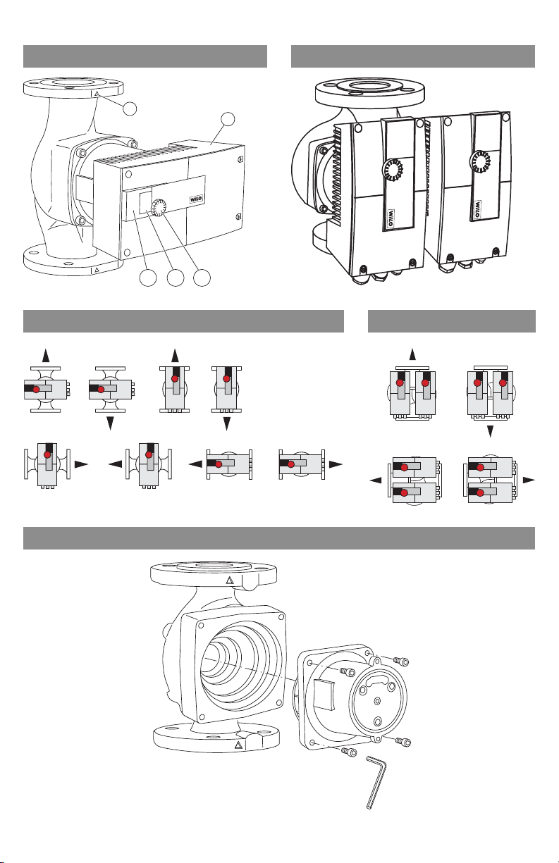
Fig. 1a: Fig. 1b:
2
1.1
1.2
1
1.3
Fig. 2a: Fig. 2b:
Fig. 3:
Page 3
230V~
FC
Achtung
Achtung
Option
IF-Modul
Netzspannung
Attention
Mains Voltage
Attention
1 -
23
0V
!
Q
Hs
H
max
H
Q
H
s
½Hs
H
min
H
s
1
1
2
2
Q
1
2
Hs
H max
H
H
s
Hmin
Hs
1
2
Fig. 4: Fig. 5:
Fig. 6: Fig. 7:
H
Fig. 8:
Hs Hs
Hs max
Hs min
T min T max T med
Hs var.
Q min Q max Q
Page 4
Q
Hs
H
n
s
= const
n
max
= const
H
s
10 U[V]1 2 3
Off / Aus
H min / n min
H max / n max
H/n
Fig. 9: Fig. 10:
Page 5

Installation and operating instructions ..................................................................3
1 General ................................................................................................................................... 3
2 Safety ..................................................................................................................................... 3
3 Transport and interim storage ............................................................................................5
4 Intended use (Application) ..................................................................................................5
5 Product details ......................................................................................................................6
6 Description and function ..................................................................................................... 7
7 Installation and electrical connection .............................................................................13
8 Commissioning ...................................................................................................................18
9 Maintenance/service ..........................................................................................................29
10 Faults, causes and remedies .............................................................................................30
11 Spare parts ...........................................................................................................................34
12 Disposal ................................................................................................................................34
Notice de montage et de mise en service ........................................................... 35
1 Généralités ..........................................................................................................................35
2 Sécurité ................................................................................................................................35
3 Transport et entreposage provisoire ...............................................................................37
4 Utilisation (application) prévue ........................................................................................37
5 Détails produit ....................................................................................................................39
6 Description et fonctionnement ........................................................................................40
7 Installation et raccordement électrique ..........................................................................46
8 Mise en service ....................................................................................................................51
9 Entretien/Service ................................................................................................................62
10 Défauts, causes et mesures de dépannage ....................................................................63
11 Pièces de rechange .............................................................................................................67
12 Élimination ...........................................................................................................................67
Instrucciones de instalación y operación ............................................................ 69
1 Información general ...........................................................................................................69
2 Seguridad .............................................................................................................................69
3 Transporte y almacenamiento ..........................................................................................71
4 Uso previsto (aplicación) ...................................................................................................71
5 Detalles del producto .........................................................................................................72
6 Descripción y funcionamiento ..........................................................................................74
7 Instalación y conexión eléctrica .......................................................................................80
8 Puesta en servicio ...............................................................................................................85
9 Mantenimiento/servicio técnico ......................................................................................96
10 Fallas, causas y soluciones ................................................................................................97
11 Refacciones .......................................................................................................................102
12 Desecho .............................................................................................................................102
1
Page 6

2
Page 7
1 General
About this document
These Installation and Operating Instructions form an integral part of the
product. They must be kept close to the product and in readiness whenever
required. Precise observance of these instructions is a pre-condition for use of
the product for the intended purpose and for its correct operation.
These Installation and Operating Instructions conform to the relevant version of
the equipment and the underlying safety standards valid at the time of going to
press.
2Safety
These instructions contain important information which must be followed when
installing and operating the pump. It is therefore imperative that they be read
by both the installer and the operator before the circulator is installed or started
up.
Both the general safety instructions in the ‘Safety precautions’ section and
those in subsequent sections indicated by danger symbols should be carefully
observed.
2.1 Symbols and signal words used in these operating instructions
Symbols:
General Safety symbol
English
Hazards from electrical causes
NOTE:
Installation and operating instructions Wilo-Stratos /-D/-Z 3
Page 8
English
Signal words:
DANGER!
Imminently hazardous situation.
Will result in death or serious injury if not avoided.
WARNING!
The user can be exposed to (severe) injury. 'Warning' refers that harm to the
user when the user is neglecting the procedure.
CAUTION!
The product is at risk of damage. 'Caution' refers to the product when the
user is neglecting the procedures.
NOTE: A notice with useful information for the user in relation to the product. It
attends the user to possible problems.
2.2 Qualified Personnel
The personnel installing the pump must have the appropriate qualifications for
this work.
2.3 Risks incurred by failure to comply with the safety precautions
Failure to comply with the safety precautions could result in personal injury or
damage to the pump or installation. Fail
ure to comply with the safety
precautions could invalidate warranty and/or damage claims.
In particular, failure to comply with these safety precautions could increase the
possibility of the following risks:
• the failure of important parts of the pump or installation,
•personal injury due to electrical and mechanical causes,
•material damage.
2.4 Safety precautions for the operator
Existing regulations for the prevention of accidents must be observed.
National Electrical Codes, local codes and regulations must be followed.
This device is not intended to be operated by persons (including children) with
impaired physical, sensory or mental capacities or lack of experience and/or la
of knowledge, except in cases where they are supervised by a person
responsible for their safety or where they receive instructions from such a
person as to how the device is to be operated. Children must be kept under
supervision in order to ensure that they do not play with the device.
2.5 Safety precautions for inspection and installation
The operator must ensure that all inspection and installation work is carried out
by authorized and qualified speci
alists who have carefully reviewed these
instructions.
Work on the pump/unit must be carried out only with the pump disconnected
(locked out) from the electrical supply and at complete standstill.
4 Subject to technical alterations!WILO SE 02/2011
ck
Page 9
2.6 Unauthorized alterations and manufacture of spare parts
Alterations to the pump or installation may only be carried out with the
manufacturer's consent. The use of original spare parts and accessories
authorized by the manufacturer will ensure safety. The use of any other parts
may invalidate claims involving the liability of the manufacturer for any
consequences.
2.7 Improper use
The operational safety of the pump or installation supplied can only be
guaranteed if it is used in accordance with paragraph 4 of the operating
instructions. The limits given in the catalogue or data sheet must under no
circumstances be exceeded.
3 Transport and interim storage
When receiving the material, check that there has been no damage during the
transport. If shipping damage has occurred, take all necessary steps with the
carrier within the allowed time.
CAUTION! Outside influences may cause damages!
If the delivered material is to be installed later on, store it in a dry place and
protect it from impacts and any outside influences ( humidity, frost etc.).
Handle the pump carefully so as not to damage the unit prior to installation.
English
4 Intended use (Application)
CAUTION! Possible damage of the pump!
This pump is intended for use with water and water/glycol only .
The high-efficiency pumps of the Wilo-Stratos/-D/-Z series are used to
circulate fluids (no oil or oleiferous fluids, no foodstuffs) in
•Hot water heating systems,
• Cooling and cold water circuits,
•Closed circulation systems.
WARNING! Health hazard!
The materials of the Wilo-Stratos/-D can cause damage to one's health,
since they are not approved for use in secondary hot water circulation
systems.
Do not use Wilo-Stratos/-D pumps in secondary hot water systems.
Permissible liquids and requirements:
•Heating water according the requirements of accepted standards of water
quality in heating systems.
Installation and operating instructions Wilo-Stratos /-D/-Z 5
Page 10
English
•Water and water/glycol mixtures in a maximum ratio up to 1:1. High glycol
concentration and low temperature systems may require a reassessment of the
hydraulic data to compensate for the increased viscosity (please contact your
WILO representatives for more information). Use of additives (corrosion
inhibitors, oxygen sc
manufacturer instructions.
avengers etc.) must be in compliance with the
•If other fluids or additives are used, please contact WILO for proper
authorization.
CAUTION! Possible damage of the pump!
Unacceptable fluids may destroy the pump.
Observe the specifications of the manufacturer regarding the mixing ratios.
Add additives to the fluid on the pressure side of the pump.
The high-efficiency pumps of the Wilo-Stratos-Z series are also suitable for use
in
• Secondary hot water circulation systems
5 Product details
5.1 Type key
Example: Stratos-D 2x3-40
Stratos High-efficiency pump
Wet-rotor circulating pump
D = single-head pump (no letter)
-D = twin-head pump
-Z = single-head pump for secondary hot water circulation systems
2 Pipe connection [inch]
3-40 Infinitely variable nominal pump head 3 to 40 [ft]
H
min
: 3.3 ft, H
max
: 39.4 ft
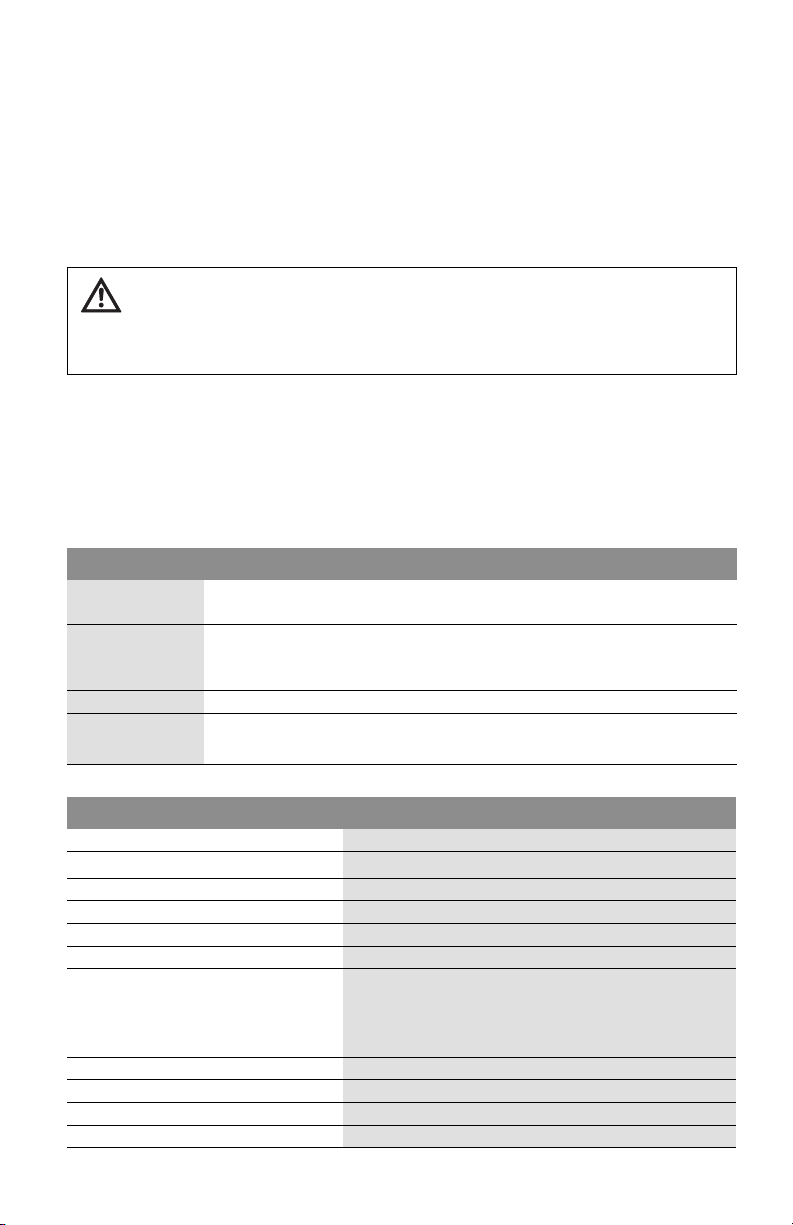
5.2 Technical Data
Power supply 1~230 V ± 10%
Frequency
60 Hz
Degree of protection Enclosure 2
Insulation class
Motor protection
H
Standard built-in full motor protection
Maximum sound pressure level 54 dB(A)
Liquid temperature
Heating, ventilation, air-conditioning applications:
14°F (-10°C) to 230°F (+110°C)
Secondary hot water circulation applications:
32°F(0°C) to 176°F(+80°C )
Max. ambient temperature 104°F (40°C)
Max. rel. humidity 95%
Max. working pressure at the pump
Residual current
6 Subject to technical alterations!WILO SE 02/2011
145 psi
I 3.5 mA (see also Chap. 7.2)
Page 11

English
Min. pump inlet pressure [psi] at the suction side during operation by WiloStratos model:
At these liquid temps T
14°F...122°F
(- 10°C...+50°C)
Med
203°F
(+95°C)
230°F
(+110°C)
1.25 inch 4.4 (psi) 14.5 (psi) 23.2 (psi)
1.5 and 2 inch 7.3 (psi) 17.4 (psi) 26.1 (psi)
3 inch 10.2 (psi) 21.8 (psi) 33.4 (psi)
The values apply up to 984 ft above sea level, add-on for higher altitudes:
0.15 psi/328 ft increase in height
5.3 Scope of Supply
• Complete pump
•Installation and operating instructions
•2 flange gaskets (only for 1.25, 1.5 and 2 inch flange pumps)
5.4 Accessories
• Accessories such as companion flanges must be ordered separately.
•Companion flanges (included bolts, nuts and gaskets) for flange-pipe connection.
• IR (infra-red) module for special setup and diagnostics.
• IF (interface) Module Stratos Ext. Off/SBM, Ext.Min, LON, BACnet.
6 Description and function
6.1 Pump description
Wilo-Stratos high-efficiency pumps are glandless pumps with integrated
differential pressure control and “Electronic Commutated Motor” (ECM)
technology. They can be installed as single-head (Fig. 1a) or twin-head pumps
(Fig. 1b).
1 Control module
1.1 Infrared interface
1.2 LC display
1.3 Red button
2 Pump housing
6.2 Operation of the pump
If the pump has an axial design, there is a control module (Fig. 1a, Pos.1) on the
motor housing, which regulates the differential pressure of the pump to an
adjustable setpoint within the control range. The differential pressure is based
on different criteria, depending on the control mode. In all control modes,
however, the pump constantly adapts to the changing output requirements of
the system, which arise in particular when using thermostatic valves, zone
valves or mixers.
Installation and operating instructions Wilo-Stratos /-D/-Z 7
Page 12
English
The main benefits of electronic control are:
•it saves energy while reducing operating costs,
• it reduces noise caused by the excess flow,
• it does not require pressure bypass valves.
This wet rotor pump is designed to have all rotating parts surrounded by the
liquid being pumped. The pump is maintenance free and requires no further
maintenance after the air bleeding procedure during the initial start-up (no
after start-up maintenance).
High-efficiency pumps of the Wilo-Stratos-Z series are adapted specifically to
the operating conditions in secondary hot water circulation systems due to the
materials selected and their design. All materials which come into contact with
the fluid are approved in accordance with KTW/WRC (WRAS).
6.2.1 Operating modes
The Stratos series can be operated in the operating modes “Heating” or
“Cooling/ air-conditioning”. The two operating modes are distinguished from
one another in their tolerance for faults in the handling of fault signals that
occur.
“Heating” operating mode:
Faults are handled in a tolerant fashion (as is normally the case), e.g. depending
on the type of fault, the pump does not signal a fault until the same fault has
occurred repeatedly within a particular time period. Error matrix: “HV”
“Cooling/air-conditioning” operating mode:
For all applications for which each fault (in the pump or the system) must be
recognised quickly (e.g. air-conditioning applications).
Each fault, with the exception of the fault E10 (blocking), will be signalled at
once (< 2 sec.). In the event of a blocking (E10), various restart attempts will be
carried out, which means that in such cases no fault message will occur until
after a maximum of 40 sec. Error matrix: “AC”
Both operating modes distinguish between faults and warnings. In the event of
a malfunction, the motor is switched off, the error code on the monitor is
displayed and the malfunction is signalled with the red LED.
Malfunctions always lead to activation of the SSM.
In the case of twin-head pump management (twin-head pump or 2x singlehead
pumps), the standby pump starts within the time period specified below
following the appearance of the fault.
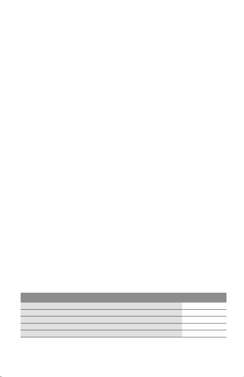
Stratos, Stratos-D, Stratos-Z Starting time
1.25x3-20, 1.25x3-25 approx. 9 sec
1.25x3-30, 1.25x3-35, 1.5x3-25 approx. 4 sec
1.5x3-40, 2x3-30, 2x3-35, 2x3-40 approx. 4 sec
3x3-30 approx. 3 sec
3x3-40 approx. 7 sec
8 Subject to technical alterations!WILO SE 02/2011
Page 13
6.2.2 Differential-pressure control systems
The control systems which can be selected are:
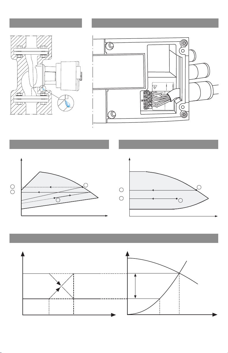
• 'p-v: (Factory default setting) The electronics increase the pump's differential
pressure set point in a straight line between ½ Hs and Hs. The differential
pressure set point Hs increases or decreases in accordance with the required
flow rate (fig. 6).
• 'p-c: The electronics keep the differential pressure generated by the pump at
a constant differential pressure set point Hs over the entire operation range of
the pump (fig. 7).
• 'p-T: The electronics alter the nominal differential pressure set point
dependant on the fluid temperature measured. This control system can only be
adjusted with the IR module. There are two possible settings (fig. 8):
•Positive control: As the system temperature rises, the nominal differential
pressure set point is increased linearly between Hsmin and Hsmax. (setting on
IR module: Hs
max
> Hs
min
).
Used e.g. with standard boilers with sliding flow temperature.
•Negative control: As the system temperature rises, the nominal differential
pressure set point is decreased linearly between Hsmin and Hsmax (setting on
IR module: Hs
max
< Hs
min
).
Used e.g. with condensing boilers where a specific maxium return water
temperature must be maintained to achieve as much condensing as possible
to insure maxium boiler effeciency. To do this, the pump must be installed in
the system's return flow section.
English
6.2.3 Other energy-saving operating modes
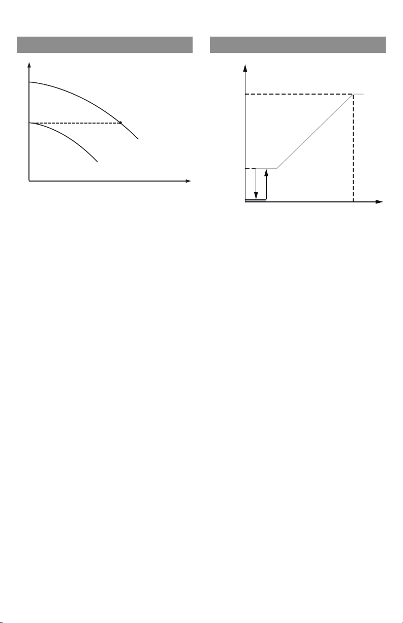
• Speed regulation mode operation: The speed of the pump is kept at an
externally set constant speed between minimum and maximum speeds (fig. 9).
The speed regulation mode deactivates the differential pressure control.
• In the "auto" operating mode (factory default setting) the pump is able to
recognize a minimum system heat output requirement due to a sustained drop
in the system temperature and then automitically switch to night setback
mode. If the heat output requirement rises, the pump automatically switches to
standard mode. This setting ensures that the pump's energy consumption is
reduced to a minimum and in most cases is the optimum setting.
CAUTION! Possible damage of the pump!
Setback mode may only be enabled when the system is hydraulically
balanced. Inadequately supplied system parts may otherwise freeze in the
event of frost.
6.2.4 General pump functions
• The pumps are fitted with an electronic overload protection system which
switches the pump off should it become overloaded.
• The control modu
le is equipped with a non-volatile memory for data storage.
What this means is that data is saved, even during long periods of down time.
Once the voltage returns the pump starts operating again with the values set
before the power outage.
Installation and operating instructions Wilo-Stratos /-D/-Z 9
Page 14

English
• Pump kick: Any pumps switched off via the menu (ON/OFF), a bus
communication, the infrared interface, the Ext.Off control input or 0-10V start
running for a short time every 24 hours to prevent blockages in the event of long
periods of standstill. The mains voltage must not be interrupted for this
function.
If the mains is intended to be switched off for a long period of time, the pump
kick must be assumed by the heating/boiler control system by briefly switching
on the mains voltage. For this purpose, the pump must be switched on by the
control system prior to the interruption to the mains supply (display o motor/
module symbol lit up).
Connections to the building management system (BMS)
• FC: A collective fault contact FC (potential-free closed contact) can be
connected to a control point (building management system) as standard. The
internal contact is closed if the pump is turned off, or there are no problems or
failures on the part of the control module. The faults are described in detail in
chapter 10.
• IF(Interface) modules (accessory):
Analog interfaces are available in the form of add-on IF modules for connecting
to external control system (e.g. DDC/BMS).
6.2.5 Twin-head pump operation
Twin-head pumps or two corresponding single pumps in a parallel pump
installation can be fitted with built-in double-pump management.
• Stratos IF module: Two IF modules connected via the DP (double pump)
interface are required for communication between pumps. In addition to double
pump management, the IF modules provide other interfaces for the double
pump.
This double pump management has the following functions:
• Master/Slave: Both pumps are controlled by the master. All settings are made
by the master.
• Optimum-efficiency peak-load operation: The twin-head pumps or two
corresponding single pumps can be run in a low/high flow application where if
the lead pump can not keep up with the flow demand the lag pump will operate
automatically. At partial load, the hydraulic capacity is provided by one pump
only. The second pump is switched on at optimum efficiency, when the sum of
power consumptions P1 of both pumps is less than the power consumptions P1
of one pump. Both pumps are then adjusted upwards simultaneously to max.
speed if necessary. In relation to the conventional peak load operation (load
controlled switch on and off) a further energy saving is reached by this mode of
operation.
• Duty/Standby mode: Each of the two pumps produces the design delivery rate.
The other pump can be used in the event of
the first pump malfunctioning or
following a pump swap. Only one pump operates at a time.
• In the event that one pump experiences a failure/problem, the other will run as
a single pump in standard mode as instructed by the master.
10 Subject to technical alterations!WILO SE 02/2011
Page 15
English
• In the event of a break in communication: The slave pump runs at the last set
value of the master prior to the interruption.
• Pump swap: If only one pump is operational (duty/standby, peak- or low-load
operation), the pumps are swapped after every 24 hrs’ of actual operating time.
Both pumps are running at the time of the pump alteration in order to en
sure
that operation is not interrupted.
NOTE: Both pumps will always be running if both the manual control mode and
the synchronous mode are active at the same time.
No pump alteration takes place. No pump alteration takes place during the
active night reduction after 24 h of effective running time.
• FC: The collective fault contact (FC) of the master can be connected to a centr
control point. In this case, contact is only established with the master. The
reading is valid for both pumps.
As an option, the error message contacts of master and slave can be
programmed as single fault signal with the IR module. For the single fault
signals, contact must be established with each pump.
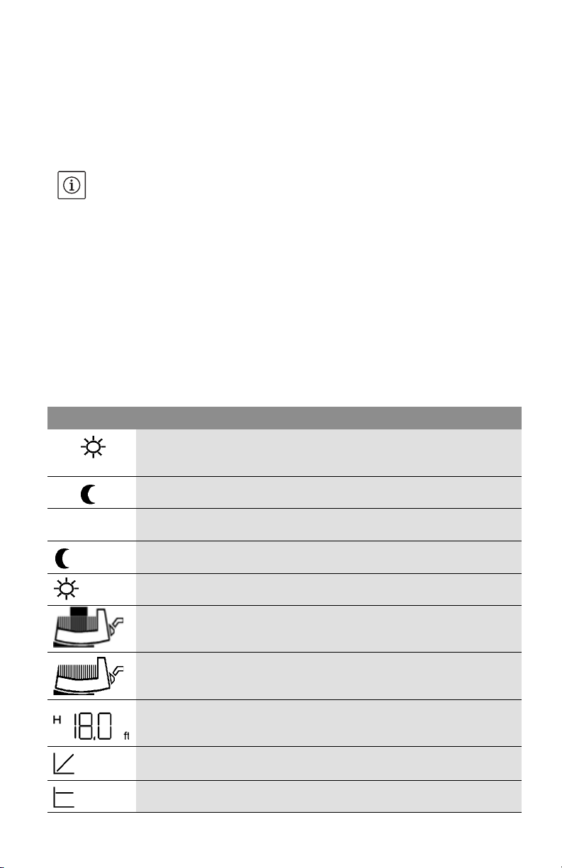
6.2.6 Definition of the symbols on the LC display
Symbol Definition
Control mode; automatic switch-over to night setback mode is enabled.
auto
Night-time mode is activated at minimum heat output requirement
(default).
Pump runs in night-time mode (night setback operation) at min. speed.
auto
(no symbol)
Automatic switch-over to night setback mode blocked, i.e. pump runs in
standard mode only.
Night setback mode activated via PLR/LON/CAN interface Ext.Min,
regardless of the system temperature.
Pump runs in warm-up mode at maximum speed. The setting can be
activated only via PLR/LON/CAN.
Pump switched on (default).
Pump switched off.
al
Differential pressure set value set to H = 18.0 ft. (example)
Control mode 'p-v, regulated to variable differential pressure set value
(fig. 6) (default).
Control mode 'p-c, regulated to constant differential pressure set value
(fig. 7).
Installation and operating instructions Wilo-Stratos /-D/-Z 11
Page 16
English
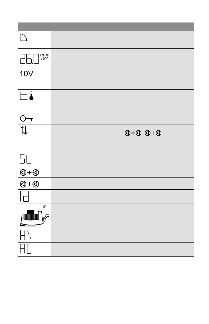
Symbol Definition
Manual control mode deactivates the module pressure variations. The
speed of the pump is kept at a constant level. The speed is set internally
using the contol button (fig. 9).
Pump set to a constant speed (2.600 rpm example shown) - manual
control mode.
In the manual control mode, the speed or nominal lift of operating mode
'p-c or 'p-v of the pump is set via input 0...10 V of the Stratos IF
module Ext.Min. The button then has no set value input function. (fig.
10)
Control mode 'p-T, regulated to temperature dependent differential
pressure set value (fig. 8). The maximum set value Hs
is displayed.
max
This control mode can only be activated via the IR module or via PLR/
LON/CAN.
All settings on module except "acknowledge error" blocked. Settings
locked out by IR module. Settings can only be altered using IR .
The pump is operated via a serial data interface. The “On/Off” function
is not activated at the module. Only , , the display
position and fault acknowledgement still have to be set on the module.
Operation at the interface can be interrupted temporarily with the IR-
Monitor/IR-module (for inspection or for reading out data).
Pump runs as slave pump. No changes can be made to the position
setting of the display.
Two single pumps as double pump running in peak load mode (master +
slave)
Two single pumps as double pump running in duty / standby mode
(master or slave)
Displayed for pump with IF module LON in order to send a service mes-
sage to the building control centre.
The pump is set in the “SI units” mode.
Fault-tolerant error matrix activated.
Heating operating mode (in case of malfunction, see Chap. 10)
Fault-tolerant error matrix deactivated.
Air-conditioning operating mode (in case of malfunction, see Chap. 10)
12 Subject to technical alterations!WILO SE 02/2011
Page 17
Menu structure: There are three menu levels. The levels beneath the display of
the basic settings are always accessed from 1 level by pressing the control
button
for different lengths of time.
Level 1 – Status display (display of the operating state)
Level 2 – Operation menu (setting the basic functions):
•Pressing the control button longer than 1 s
Level 3 – Options menu (additional settings):
•Pressing the control button longer than 6 s
NOTE: After 30 s without any new entry being made, the display jumps back to
Level 1 (display of the operating state). Temporary, non-acknowledged
modifications are discarded.
7 Installation and electrical connection
Installation and electrical work in compliance with any local codes and by
qualified personnel only!
DANGER! Electrical shock hazard!
Dangers caused by electrical energy must be excluded.
National Electrical Codes, local codes and regulations must be followed.
WARNING! Bodily injury!
Existing regulations for the prevention of accidents must be observed.
English
7.1 Pump installation
•Installation within a building: install the pump in a dry, well ventilated and
frostresistant room.
•Installation outside a building (outdoor installation):
•Install the pump in a shaft (e.g. light well, annular shaft) with cover or in a
cupboard/housing as weather protection.
• Avoid exposure of
the pump to direct sunlight.
• Protect the pump against rain. Dripping water from above is permitted,
provided the electrical connection is established in accordance with the
installation and operating instructions and the terminal box is closed properly.
CAUTION! Possible damage of the pump!
Dirt and solder drops in the pump body can effect the pump operation.
• It is recommended that any welding and soldering work be done before
installing the pump.
• Thoroughly flush the system prior to installing and operating the pump.
• Foreign material in the system resulting from construction may damage the
pump and is not warrantable.
Installation and operating instructions Wilo-Stratos /-D/-Z 13
Page 18
English
• The pump must be installed in an easily accessible position to facilitate
inspection or replacement.
•The pump should never be located at the lowest point of the piping system,
where dirt and sediment collect. Nor should it be located at the highest point of
the piping system, where air accumulates. Please ensure at least a minimum of
three pipe diameters of straight on the suction side of the pump.
•It is recommended that isolation valves be installed on the suction and
discharge side of the pump.
This will save having to drain and refill the system if the pump / pump head
needs exchange-service. The valves are to be installed so that any water that
escape cannot drip onto the pump motor or terminal box.
• An arrow on the pump housing indicates the direction of water flow (fig.1, pos.2).
•Install the pump in an easily accessible place, so that subsequent servicing work
can easily be carried out.
Installation is to be carried out such that dripping water cannot drip onto the
pump motor or control module.
•Pump must be installed with the shaft in the horizontal position in such a way
that it is not stressed by the pipework. (Installation positions in fig. 2). When
installing in confined spaces, for example in compact distributors, the control
module can be placed in a vertical position by rotating the motor, see
chapter 7.1.1.
• In order to obtain the correct terminal box position the motor housing can be
turned after removing the four allen screws (fig. 3).
WARNING! Risk of scalding!
If the pump is already installed in the system, the system must be drained or
the isolating valves on both sides of the pump must be closed before the
allen screws are removed as the pumped liquid may be scalding hot and/or
under pressure.
Do not start the pump until the system has been filled with liquid and
vented.
• Permitted terminal box positions see fig. 2
CAUTION! Possible damage of the pump!
When rotating the motor housing, ensure the O-ring between the cartridge
and pump housing (volute) does not become damaged.
•Carefully lift the pu
mp head and rotate it so the terminal box is in the desired
position. Replace the pump head onto the pump housing and thighten the allen
screws evenly in a diagonal method.
Torque to:
• M6 ............ 7 ft lb
• M10 ........22 ft lb
14 Subject to technical alterations!WILO SE 02/2011
Page 19
DANGER! Electrical shock hazard!
If the pump is operated by means of a generator, a dangerous voltage is
created at the motor terminals after the control module is removed. The
motor terminals are designed as VDE-approved bushings, so that there is no
danger if simply touched with the finger. However, there would be a danger
if a pointed object (nail, screwdriver, wire) were poked into one of the
bushings.
7.1.1 Removing/installing the motor head unit
If the control module is to be moved into a different position, the motor does
not need to be completely removed from the pump housing. The motor can be
turned to the desired position in the pump housing.
CAUTION! Possible damage of the pump!
Be careful not to damage the O-ring situated between the motor head and
the pump housing. The O-ring must lie untwisted in the bevel of the end
shield pointing to the impeller.
CAUTION! Possible damage of the pump!
The impeller is permemtantly attached to the shaft, the end shield and the
rotor. As the rotor has extremely strong rare earth magnets, if the rotor is
removed from the rotor can, it has a considerable potential for danger e.g.
by suddenly attracting objects made from iron/steel, influencing electrical
equipment (risk to people with pacemakers), destroying magnetic cards,
etc.
English
To remove the motor, (4x) M6 or (4x) M10 hexagon socket screws must be
loosened. These screws can be reached with the following tools (fig. 3):
• 90° offset socket-head screwdriver
• spherical head socket-head screwdriver
• ¼” reversing ratchet with suitable bit
7.1.2 Insulating the pump in refrigerating/air-conditioning systems
The Wilo-Stratos series is suitable for use in refrigeration and air-conditioning
systems with flow medium temperatures down to 14°F (-10°C).
Use the diffusion-proof Wilo-ClimaForm low-temperature insulation shell in
cooling and air-conditioning systems.
CAUTION! Possible damage of the pump!
If the diffusion-proof insulation is created by the customer, the pump
housing may be insulated towards the motor only up to the motorflange, so
that the condensate drain openings remain open and allow the condensate
accumulating in the motor to flow out without obstruction (fig. 4).
Installation and operating instructions Wilo-Stratos /-D/-Z 15
Page 20
English
7.2 Electrical connection
DANGER! Electrical shock hazard!
Dangers caused by electrical energy must be excluded.
• Electrical work by a qualified electrician only!
• National Electrical Codes, local codes and regulations must be strictly
followed.
• All electrical connections must be performed after the electrical supply has
been switched off and secured against unauthorized switching.
• For safe installation and operation a proper grounding of the pump to the
power supply’s grounding terminals is required.
•Suitable mains fuse is required to protect the motor per local electrical codes.
• The operating voltage and frequency are marked on the rating plate.
• The pump must be connected with a power supply equipped with a grounded
plug-connection and a main power switch.
• A minimum cable size of 14 AWG should be used (refer to the local code for
wiring restrictions).
CAUTION! Possible damage of the pump!
All conductors must be for at least 167°F (75°C).
•The following minimu
m requirements are to be met if a shutdown takes place
by means of an onsite network relay: nominal current 10 A, nominal voltage
250 VAC.
•Leakage current per pump I
3,5 mA
eff
• The electrical cable must be installed so that it never touches the pipework and/
or the pump and motor housing.
• The connecting cable can be fed through the cable entry below or beside the
terminal box, depending on it’s orientation. It is advisable to install the screwed
cable glands with the entrance of the conduit pointing downwards. The cable
entry which is not used must be closed by a blind plug (fig. 5).
•Watertight screwed cable glands and conduit connections must be used to
prevent any entrance of water to the terminal box.
• Connect power as shown in fig. 5.
•Mains fuse: see rating plate
•Pump/installation must be grounded in compliance with regulations.
CAUTION! Possible damage of the pump!
In insulation tests with a high-voltage generator the pump is to be
disconnected on all poles from the mains in the control module. The free
cable ends are to be insulated in accordance with the voltage of the highvoltage generator.
16 Subject to technical alterations!WILO SE 02/2011
Page 21
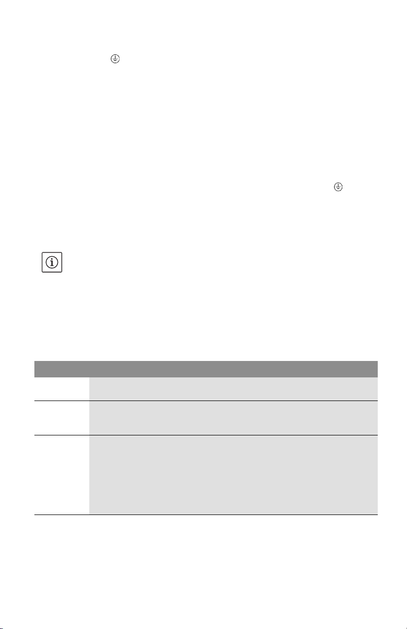
7.2.1 Electrical pump connection (fig. 5)
• 230 V~, : Mains voltage, single-phase current 1~230 VAC ±10%, 60 Hz
Voltage across terminals “230V~” must be total 230 volt
either
• 230 volt “hot” lines and neutral line
or
• two 230 volt “hot” lines.
• FC: A built-in collective fault signal is available on the FC (fault contact)
terminals as a potential-free closed contact.
Permissible contact load:
• minimum: 12 V DC, 10 mA,
•maximum: 250 VAC, 1 A.
Max. tightening torque of the connecting terminal screws (230 V~, , FC):
2.2lbinch
• Twin-head pumps or two single pumps as double pump:
Both motors in the parallel pump installation are to be provided with a separate
mains cable and a separate mains fuse protection.
NOTE: If a single motor in a parallel pump installation is switched off-load, the
built-in double-pump management is deactivated.
• Switching frequency:
• On-/Off switching by mains supply d 20 times / 24 h
• On-/Off switching by Ext. Off or 0...10 V Signal d 20 times/ h
• Assignment of supply terminals: The following table shows the possibilities for
which combinations of circuits the individual cable glands in a cable can be
assigned.
English
Cable gland ½” Cable gland ¼” Cable gland PG 7
Function Mains cable FC
Cable type 5x14 AWG
Function Mains cable FC
Cable type 3x14 AWG
2-core cable
3x14 AWG
Function Mains cable FC / Ext.Off / SBM
DP-management
or
FC / 0...10 V / Ext.Min
Cable type 3x14 AWG
3x14 AWG
3x14 AWG
multicore control
cable, number of cores
in acc. with number of
2-core cable (l d 2.5 m)
circuits, if nec. shielded
Installation and operating instructions Wilo-Stratos /-D/-Z 17
Page 22
English
8 Commissioning
8.1 Filling and Venting
• Proper fill and pressurize the system with liquid.
CAUTION! Possible damage of the pump!
Never operate the pump dry.
The system must be filled before starting the pump. Ensure that all isolation
valves are open.
• The pump is normally vented automatically after a short operational period.
WARNING! Risk of burning!
Depending on the operating condition of the pump and/or installation (fluid
temperature) the entire pump can become very hot.
Avoid touching the pump owing to the risk of burning.
The temperature at the heat sink can be up to 158°F (+70°C) within the
permissible operating conditions.
8.2 Setting the menu
8.2.1 Using the control button (fig. 1, pos. 1.3)
• From the basic setting, the setting menus are selected one after another by
pressing the button (press longer than 1 second for the first menu). The current
symbol flashes. The parameters can be moved backwards or forw
display by turning the button clockwise or anti-clockwise. The newly set symbol
flashes. The new setting is applied and the next setting option is activated by
pressing the button.
• The setpoint (differential pressure or speed) is changed in the basic setting by
turning the control button. The new value flashes. The new setpoint is saved by
pressing the button.
• The old value is retained and the basic setting is displayed again if the new
setting is not confirmed within 30 seconds.
ards on the
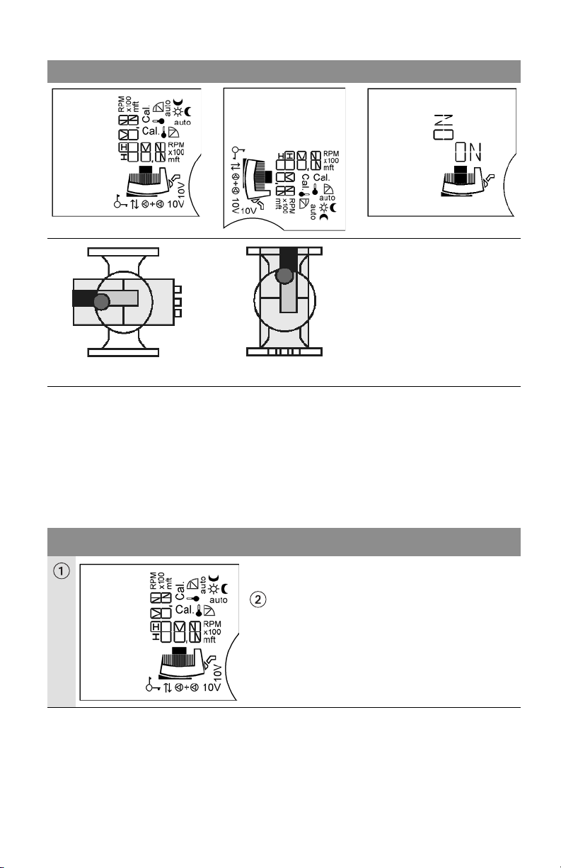
8.2.2 Switchover of the display
It can be set whether the display is to be turned by 90° for the respective
arrangement of the control module, depending on whether it is installed in
horizontal or vertical position. The positional setting can be made in
menu point 3. The display position specified by the basic setting flashes with
“ON” (for horizontal installation position). The display can be switched over by
turning the setting knob. “ON” flashes for the vertical installation position. The
setting is confirmed by pressing the setting button.
18 Subject to technical alterations!WILO SE 02/2011
Page 23
Switchover of the display
English
Horizontal
Vertikal
in menu point 3
8.2.3 Settings in the menu
The following menus appear in succession on the pump display:
(horizontal representation of display)
Single pump mode: Setting when first used / Menu order during standard use
LC display Setting
After switching on the module, all symbols appear
on the display for 2 seconds. The current setting
then engages.
Position setting
Installation and operating instructions Wilo-Stratos /-D/-Z 19
Page 24
English
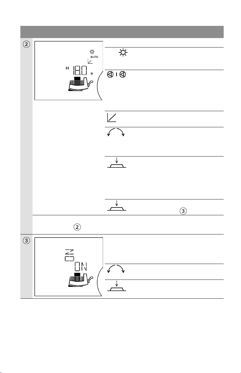
LC display Setting
Current (basic) setting (factory default):
auto • automatic night setback
enabled,
Pump runs in control mode
•missing = Single-head pump
e.g. H 18.0 ft
•present differential pressure
setpoint HS = 18.0 ft at same
time ½ Hs
depending on pump type)
• Control mode 'p-v
The differential pressure set point can
be altered by turning the control button.
The new differential pressure set point
flashes.
The new setting is stored by pressing
the button briefly.
If no button is pressed, the previously
set flashing differential pressure set
point returns to the previous value after
30 seconds
Press control button for > 1 second.
The next menu point appears.
If no setting is made in the subsequent menus for 30s,
the basic setting re-appears in the display.
Position setting of display vertical / horizontal
The set position of the display is shown by the
flashing “ON“.
By turning the control button the other
position can be selected.
Setting stored.
(factory setting
max
.
20 Subject to technical alterations!WILO SE 02/2011
Page 25
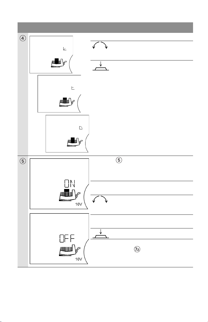
LC display Setting
The currently set control mode flashes.
Menu point only appears if a Stratos IF module
was inserted with input 0...10 V.
Switch input 0...10 V on/off
English
By turning the contro button other
control modes can be selected. The new
selected control mode flashes.
Pressing the button stores the new
control mode and switches to the next
menu.
Activate input 0...10 V: “ON” and the “module
motor symbol” appears in the display.
The setting can be altered by turning
the control button.
Deactivate input 0...10 V: “OFF” appears in the
display and the “motor symbol” disappears.
Setting stored.
If the input was switched on, the menu manager
jumps to menu point .
Installation and operating instructions Wilo-Stratos /-D/-Z 21
Page 26
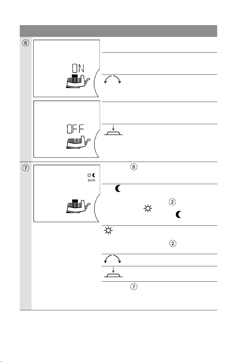
English
LC display Setting
Switch pump on/off.
Switch on pump, "ON" and the “module motor
symbol” appear in the display
Switch off pump, "OFF" appears in the display and
the “motor symbol” disappears.
Menu point is skipped if regulator mode was
selected
Either flash
auto • automatic night setback
The setting can be altered by turning
the control button.
Setting stored.
Pump runs in standard mode
Menu point then shows " auto
" during autom. control
mode or "auto " during
automatic night-setback
• normal control mode, automatic
night-setback disabled.
Menu point does not contain
any symbol.
call up one of the two s
ettings
and store.
Display jumps to the next menu.
Menu point is skipped if:
• the pump is operated at PLR/LON/CAN
•regulator mode was selected,
• the input 0...10 V was activated
22 Subject to technical alterations!WILO SE 02/2011
Page 27
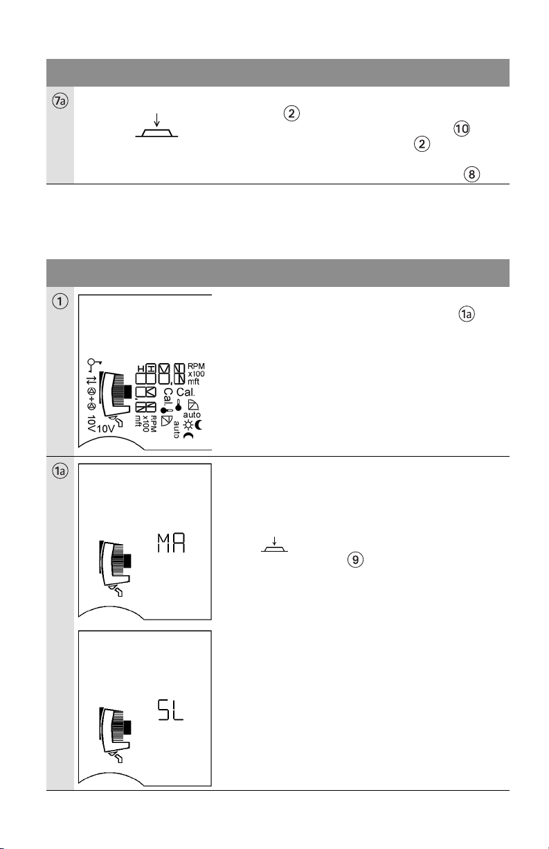
LC display Setting
In single-pump mode the display returns to basic
setting .
In the event of an error the error menu
appears before the basic setting .
In double pump mode (twin-head pump or two
single pumps) the display jumps to menu .
Double pump mode (as twin-head pump or two single pumps): Setting when
starting up for the first time
(vertical display)
LC display Setting
When the module is switched on all symbols
appear in the display for 2 seconds. Menu then
appears.
English
The symbol MA =Master appears on the display of
both pumps.
If no setting is made, both pumps run at constant
differential pressure (H
=½ H
S
where Q = 0
max.
USGM).
By on the master pump control button the
setting mode menu appears on the display.
SL =Slave appears automatically on the slave
pump display.
The configuration: left pump Master, right pump
Slave is thus selected. The control button on the
slave pump is deactivated. No more settings can be
made here.
ition setting for the display cannot be made
A pos
on the slave pump. Position setting on the slave
pump is taken over from the settings of the master
pump.
Installation and operating instructions Wilo-Stratos /-D/-Z 23
Page 28
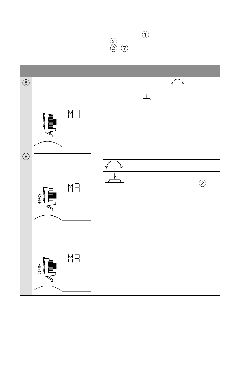
English
Double pump mode: Menu order during normal use:
After switching on the module, all symbols appear on the display for 2
seconds. The current setting then sets itself. When "scrolling" in the MA
display the same menu order ... appears as for the single pump. Then the
MA menu appears and remains on the screen permanently.
LC display Setting
SL appears on this display by on MA. The
other (right-hand) pump becomes the master if SL
is confirmed by . Master and slave have now
been exchanged. Programming can now only be
performed on the right-hand (MA) pump.
Settings c annot be made at the SL. Master and slave
can only be exchanged at the master.
Setting Peak load and duty / standby mode
The other setting blinks.
Setting stored.
Display returns to basic setting .
24 Subject to technical alterations!WILO SE 02/2011
Page 29
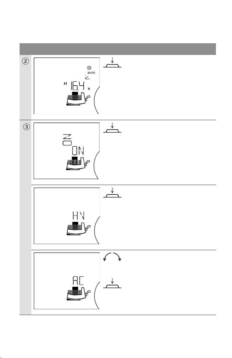
Options menu: Selection of operating mode Heating (HV) /
Refrigeration Air-conditioning (AC) and conversion from US to SI units
LC display Setting
In the basic settings (menu level 1), press
the operating button for > 6 s.
After approx. 1 s, the menu level 2
appears (position setting of the display
screen).
English
After another 5 s, the display switches to
the menu level 3
The HV display appears (works setting).
Rotating the control button will switch
the setting to the cooling/air-conditioning (AC) operating mode.
The setting is stored.
The next menu is displayed.
Installation and operating instructions Wilo-Stratos /-D/-Z 25
Page 30
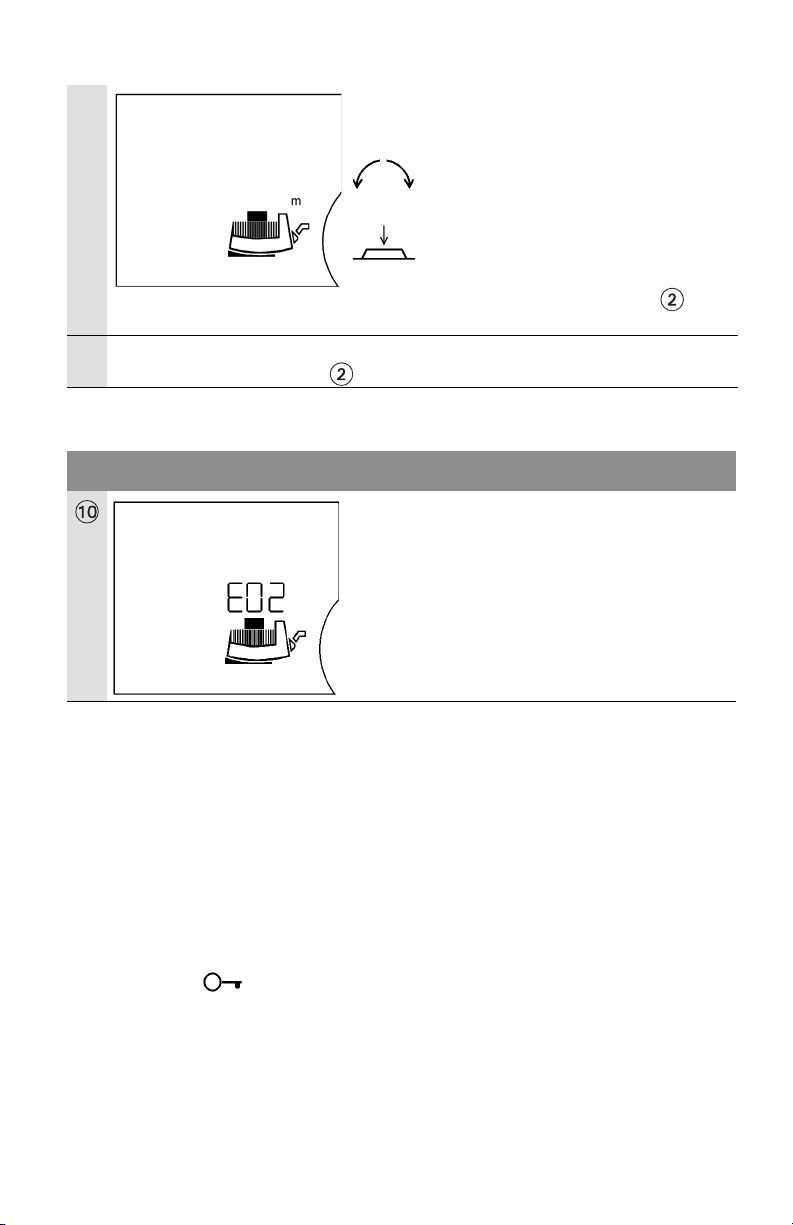
English
The display “m ft” appears, for which the
unit that is set will be flashing. (Works
setting [ft]).
Rotating the control button will change
the setting to [m]. The new setting will
begin flashing.
The new setting is saved by briefly press-
ing the button.
Display returns to basic setting .
If no setting is made in the subsequent menu within 30 s, then the display will once
again show the basic setting .
Error display
LC display Setting
In the event of an error the current error is
displayed by E = Error, the code no. and by the
flashing of the error source motor, control module
or mains connection.
For code numbers and their meaning see
chapter 10
8.2.4 Priorities on the operation of the pump, IR module
The display of errors (menu 10) incl. error acknowledgment has the highest
priority. This means that errors precedence on the pump's display and that they
must be acknowledged and removed.
If settings are made on the control module or from the IR module and not
confirmed by pressing the button, the setting will return to the previous
position 30 seconds after the last entry.
• Pump l IR witho
ut lockout function: The last command, whether from the IR
monitor or control module, is stored by the pump.
• Pump l IR with lockout function: When the "Key function on" command is
received, the control module’s current settings remain in place. The display
shows . The pump is now blocked and cannot be operated.
26 Subject to technical alterations!WILO SE 02/2011
Page 31

English
8.3 Selecting the control system
Unit type System conditions Recommended
control system
Heating-/ventilation- and
air conditioning systems
with a system friction loss
(heating radiator +
thermostatic valve) d 25%
of the total resistance
1. Two-pipe systems with thermostatic/
zone valves
• Flow head > 13.1 ft (high head
systems)
• Very long distribution lines
•Heavily throttled branch sh
ut-off
valves
•Branch differential pressure
regulator
'p-v
• High pressure losses in those
system parts through which the
total volume flows (boilers/
refrigerating machines, poss. heat
exchangers, distribution line)
2. Primary circuits with high pressure
losses
Heating-/ventilation- and
air conditioning systems
with a system friction loss
in the generator/distributor
circuit d 25% of the
resistance in the transfer
part (heating radiator +
thermostatic valve)
1. Two-pipe systems with thermostatic/
zone valves and high consumer
authority
•Flow head d 6.6 ft (low head
ystems)
s
• Converted gravity systems
• Retrofitting to large temperature
spread (e.g. long-distance energy)
• Low pressure losses in the system
parts through which the total
volume flows (boilers/refrigerating
'p-c
machines, poss. heat exchangers,
distribution line)
2. Primary circuits with low pressure
losses
3. Underfloor hea
ting systems with
thermostatic or zone valves
4. Single-pipe systems with
thermostatic or branch shut-off
valves
Installation and operating instructions Wilo-Stratos /-D/-Z 27
Page 32
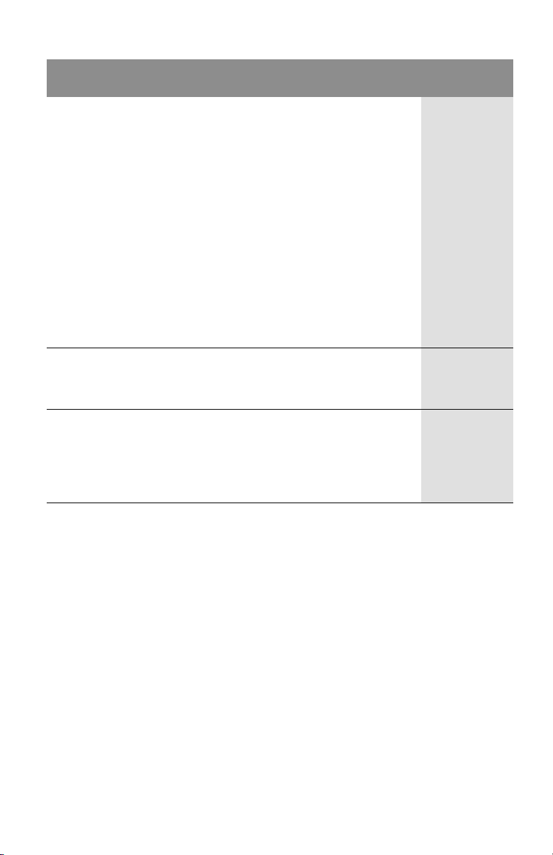
English
Unit type System conditions Recommended
control system
Heating systems 1. Two-pipe systems
•Pump installed in the supply pipe.
• Flow temperature controlled by
atmospheric conditions.
With increasing flow temperature the
flow rate will be increased.
2. Single-pipe sys
tems
•Pump installed in the return pipe.
•Constant flow temperature.
With increased return temperature
the flow rate will be lowered.
3.Primary circuits with condensing
boiler
•Pump installed in the return pipe.
With increased return temperature
the flow rate will be lowered.
Heating-/ventilation- and
1. Constant flow rate
air conditioning systems
Circulation systems for
drinking water
Heating systems 1. All systems
•Pump installed in the supply pipe.
• Flow temperature will be lowered in
Night setback
light loads periods (e.g. night).
•Pump runs 24h without external
control.
'p-T
Regulator
mode
mode
8.4 Setting the pump power
During the planning phase the system is designed for a certain duty point
(hydraulic peak load point for calculated maximum heating requirement). The
pump performance (delivery head) is set during commissioning according to the
duty point of the system (see also 4.3). The factory setting does not correspond
to the pump performance required for the system. It is determined by means of
the curve diagram for the selected pump type (from catalogue/data sheet). See
also figs. 6 to 8.
28 Subject to technical alterations!WILO SE 02/2011
Page 33
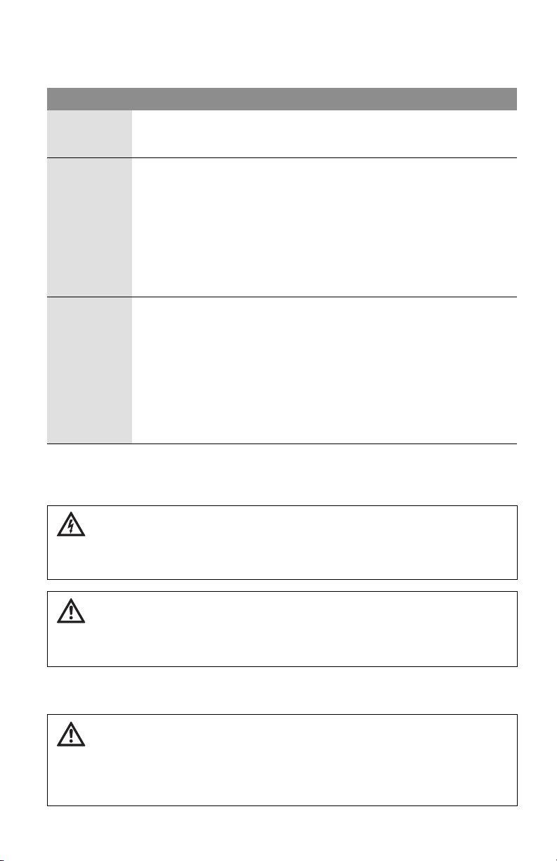
Control modes 'p-c, 'p-v and 'p-T:
Operating
point on max.
speed curve
Operating
point in
control range
Setting range H
'p-c (fig. 7) 'p-v (fig. 6) 'p-T (fig. 8)
Draw a line from the operating point to the left.
Read set value Hs and set the pump in
accordance with this value.
Draw a line from the
operating point to the
left. Read set point Hs
and set the pump in
accordance with this
value.
Continue the standard
line until it meets the
max. speed curve,
then continue
horizontally to the
left, read set point Hs
Settings are to be
made by the infrared
device.
and set the pump in
accordance with this
value.
, H
min
see type key (chapter 5.1) T
max
: 68…212°F
min
(+20...+100°C)
: 86…230°F
T
max
(+30...+110°C)
'T = T
max
50°F (10°C)
Increase:
'HS/'T d 3.3ft/50°F
(10°C) H
min
-T
, H
min
max
English
t
9 Maintenance/service
All servicing should be performed by an authorized service representative!
DANGER! Electrical shock hazard
Dangers caused by electrical energy must be avoided.
All electrical work must be performed after the electrical supply has been
disconnected and secured against unauthorized switching.
WARNING! Risk of scalding
At high water temperatures and system pressure close isolating valves
before and after the pump.
First allow pump to cool down.
These pumps are maintenance free, self-lubricated by the system fluid, and
have no seals to leak or couplings to break.
CAUTION! Possible damage of the pump
If the motor head is separated from the pump housing for servicing or repair
work, the O-ring situated between the motor head and pump housing must
be replace by a new one. When refitting the motor head, make sure the Oring is positioned correctly.
Installation and operating instructions Wilo-Stratos /-D/-Z 29
Page 34
English
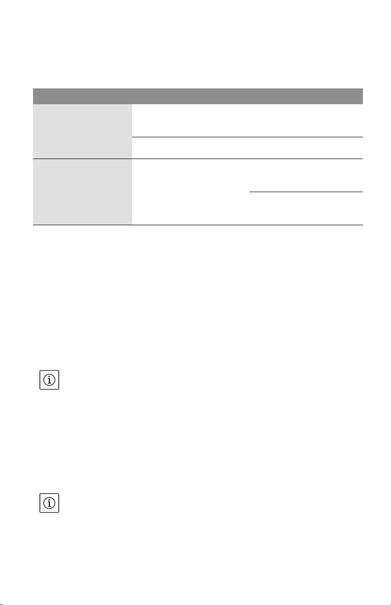
10 Faults, causes and remedies
Refer to the “Fault signal / warning message” sequence display and Tables 10,
10.1, 10.2 when handling faults.
Faults Causes Remedy
Pump is not running
although the current
entry is switched on.
Pump is making noises.Cavitation due to insufficient
Table 10: Faults with external fault sources
10.1 Fault signals – Heating/ventilation HV operating mode
• A fault occurs.
•The pump switches off, the fault signal LED (red steady light) switches on.
Twin-head pump: the standby pump is switched on.
• The pump au
• The pump is permanently switched off, FC relay opens and the PLR/LON/CAN
interface transmits the fault signal only if the same fault occurs for the sixth time
within 24 hours. The fault must then be reset by hand.
Electric fuse defective. Check the fuses.
Pump has no voltage. Resolve the voltage inter-
suction pressure.
tomatically goes on again after a delay of five minutes.
ruption.
Increase the system admis-
sion pressure within the
admissible range.
Check the delivery head and
set it to a lower height if
necessary.
EXCEPTION: If the warnings “E10” and “E25” in HV oper
ating mode are pending
for longer than 5 min, they are relayed as fault signals.
10.2 Fault signals – Air-conditioning AC operating mode
• A fault occurs.
• The pump switches off, the fault signal LED (continuous red light) is activated.
The fault signal appears in the display, FC relay opens and the interface PLR/
LON/CAN passes along the fault signal. The malfunction must then be reset
manually or via CAN.
Twin-head pump: The standby pump is switched on.
NOTE: Cod-Nrn “E04” (mains undervoltage) and “E05” (mains overvoltage) are
treated as faults only in AC operation and lead to immediate deactivation.
30 Subject to technical alterations!WILO SE 02/2011
Page 35
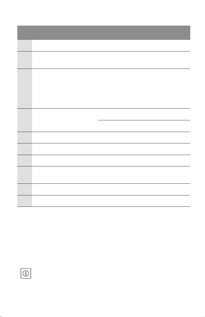
Code
Symbol
No.
flashing
E04 Supply
terminal
E05 Supply
terminal
Problem cause remedies
Mains undervoltage Mains overloaded Check electrical
installation
Mains overvoltage Faulty supply by the
electricity supply
Check electrical
installation
company
E10 Motor Pump blocked e.g. sedimentation De-blocking routine
starts automatically.
Pump switches off if
blockage is not cleared
within max.40
seconds.
Call customer services
E20 Motor winding overheated Motor overloaded Let motor cool down,
check the settings
Water temperature
to high
E21 Motor Motor overload Sediment in the
Reduce water
temperature
Call customer services
pump
E23 Motor Short circuit/contact
Motor defect Call customer services
fault
E25 Motor Contact error Module not correctly
Reinstall module
installed
E30Module Excess temperature
module
Limited air supply to
the dissipator of the
Free air intake
module
E31Module Excess temperature
power component
E36Module Module faulty Electronic
Ambient
temperature to high
components faulty
Improve ventilation in
room
Call customer service /
swap module
English
Table 10.1: Fault signals
10.3 Warning messages
• The fault (warning only) is displayed.
• The fault signal LED and the FC relay do not respond.
•The pump continues to run. The fault may occur any amount of times.
• The indicated faulty operating state must not occur for a long period of time.
The cause should be eliminated.
EXCEPTION: If the “E04” and “E05” in HV operation w
arnings apply for longer
than 5 minutes, they are transmitted as fault signals (see Section 10.1).
Installation and operating instructions Wilo-Stratos /-D/-Z 31
Page 36
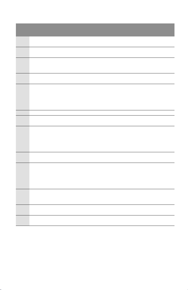
English
Code
Symbol
No.
flashing
E03 Water temperature
Problem cause remedies
> 110°C
Heating control
incorrectly set
Set to lower
temperature
E04 Mains undervoltage Mains overloaded Check electrical
installation
E05 Mains overvoltage Faulty supply by the
electricity supply
Check electrical
installation
company
E07 Generator operation Driven by admission
pressure pump
E09 Turbine operation The pump is driven
backwards (pump
perfusion from the
pressure to the
Balance pump capacity
regulation
Check circulation
direction. Fit a check
valve at the pressure
side
suction side)
E11 Pump idling Air in the pump Vent pump and unit
E38 Motor Temp. sensor
Motor faulty Call customer services
medium faulty
E50 PLR/LON/CAN
communication fault
E51 non-permissible
Interface, core
defective, IF
modules not
connected properly,
cable defective
Different pumps
The control system is
switched to local mode
control via the
interface after 5
minutes.
combination
E52 Master/slave
communication
error
Stratos IF module
not correctly
positioned, cable
faulty
After 5 min. the
modules switch to
single-pump mode.
Reinstall modules,
check cable
E53 Nonauthorised CAN
address
Same CAN address
assigned twice
Carry out addressing
on the module once
again
E54 Connection I/O -
module
Connection I/O module interrupted
Check connection
MA Master/slave not set Specify master and
slave
Table 10.2: Warning messages
If the fault cannot be remedied, please contact your local heating specialist
or Wilo customer services.
32 Subject to technical alterations!WILO SE 02/2011
Page 37
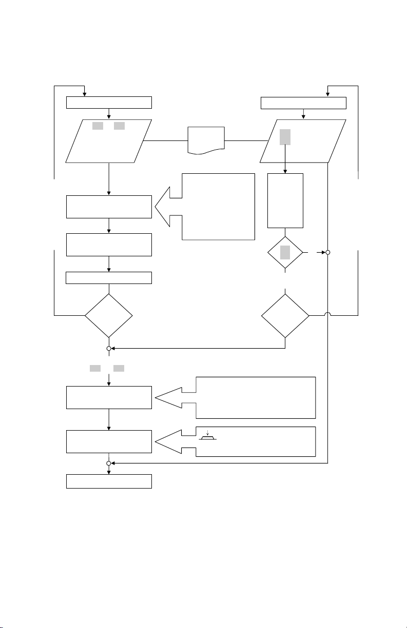
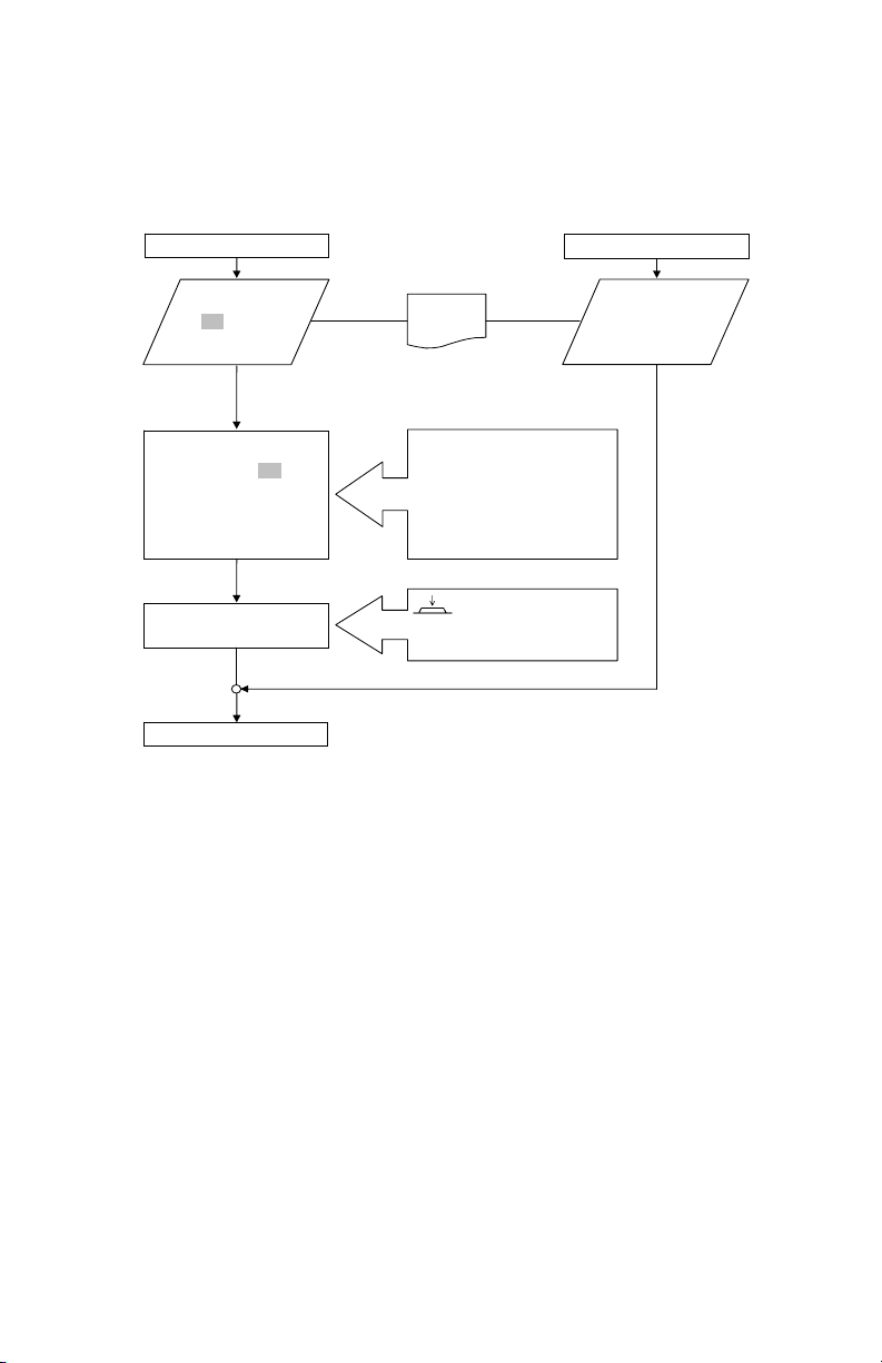
Process presentation Fault/warning signal in HV operation
Error messages: Warning messages:
Max. 5 times in 24 hrs
Less than 5 min
Error
E03 E07 E51
E04 E09 E52
E05 E11 E53
E38 E54
E50 MA
See
table
Code no.
Error LED “on“
FC opens
Error message PLR/LON/CAN
No manual reset possible
/
p
tion: E10 and E25 max. 1 time
Pump
shuts
down
while
error
present
Max. 5 times in 24 hrs
Error
E10 E25
E20 E30
E21 E31
E23 E36
PUMP shuts down
Waiting time 5 min
Manual reset
PUMP switches on
PUMP shuts down
Waiting time 5 min
Autostart
PUMP switches on
Control mode
No. of
errors in
24 hrs
Control mode
E04
E05
Longer
than 5 min
No. of
errors in
24 hrs
Code no.
Error LED “on“
DP: switch to other
pump
No manual reset possible
Operating relay SBM
opens for Stratos IF
module SBM and
Ext.Off
SBM
English
From 6 times in 24 hrs
Exce
By pressing the button for at least
1 sec the error is acknowledged.
Error can be also acknowledged via CAN
Installation and operating instructions Wilo-Stratos /-D/-Z 33
Page 38
English
Error messages: Warning messages:
Error
E03 E38 E53
E07 E50 E54
E09 E51 MA
E11 E52
See
table
Code no.
Error LED “on“
FC opens
DP: switch to other pump
Operating relay SBM opens
for Stratos IF module SBM
and Ext.Off/SBM
Error message PLR/LON/CAN
By pressing the button for at
least 1 sec the error is
acknowledged.
Error can be
also acknowledged via CAN
Error
E04 E23
E05 E25
E10 E30
E20 E31
E21 E36
PUMP shuts down
Exception: E10
Deblocking routine starts.
(max. 3 times or max. 40 s)
Pump switches of, if the
blockage is not eliminated.
Manual reset
PUMP switches on
Control mode
Process presentation Fault/warning signal in AC operation
11 Spare parts
Spare parts are ordered via local specialists and/or Wilo after-sales service. To
avoid queries and incorrect orders, all data on the name plate should be
submitted for each order.
12 Disposal
Damage to the environment and risks to personal health are avoided by the
proper disposal and appropriate recycling of this product.
1. Draw on public or private waste management companies for the disposal of
the product or components.
2. For more information on the correct disposal, please contact your local
council or waste disposal office or the supplier from whom you obtained the
product.
34 Subject to technical alterations!WILO SE 02/2011
 Loading...