

Page 1
4131015-Ed.02/2010-06 DDD
Wilo-Star RS
GB Installation and operating instructions
F Notice de montage et de mise en service
NL Montage- en bedieningsvoorschrift
I Istruzioni di montaggio, uso e manutenzione
E Instrucciones de instalación y funcionamiento
S Installations- och skötselinstruktioner
FIN Huolto- ja käyttöohje
H Beépítési és üzemeltetési utasítás
PL Instrukcja montażu i obsługi
CZ Návod k montáži a obsluze
SK Návod na montáž a obsluhu
RO Instrucfliuni de montaj øi expolatare
GR Οδηγίες εγκατάστασης και λειτουργίας
RUS Инструкция по монтажу и експлуатации
LT Montavimo ir naudojimo instrukcija
LV Uzstādīšanas un ekspluatācijas instrukcija
UK Інструкція по монтажу та експлуатації
TR Montaj ve kullanma kılavuzu
Page 2
Page 3
Page 4
N
L
N
L
N
L
N
L
/
/
1 230 V
50 Hz
a
b
c
N
L
Page 5
Page 6

GB Installation and operating instructions 7
F Notice de montage et de mise en service 13
NL Montage- en bedieningsvoorschrift 20
I Istruzioni di montaggio, uso e manutenzione 27
E Instrucciones de instalación y funcionamiento 34
S Installations- och skötselinstruktioner 41
FIN Huolto- ja käyttöohje 47
H Beépítési és üzemeltetési utasítás 53
PL Instrukcja montażu i obsługi 60
CZ Návod k montáži a obsluze 67
SK Návod na montáž a obsluhu 74
RO Instrucţiuni de montaj și expolatare 81
GR Οδηγίες εγκατάστασης και λειτουργίας 88
RUS Инструкция по монтажу и експлуатации 97
LT Montavimo ir naudojimo instrukcija 105
LV Uzstādīšanas un ekspluatācijas instrukcija 112
UK Інструкція по монтажу та експлуатації 119
TR Montaj ve kullanma kılavuzu 126
Page 7

Page 8
7
ENGLISH
1 General Information
These Operating Instructions explain
the functions and operation of the
pump when installed and ready for
use. The figures referred to in the text
can be found on the fold-out page at
the front.
Use as prescribed
The circulating pump (hereafter referred to simply as pump or general unit)
is used to pump liquids in pipe
systems.
The pump must not be
used for handling drinking
water or food related
liquids.
Its main fields of application are:
– Hot-water heating, various systems,
– Industrial, closed circulating
systems.
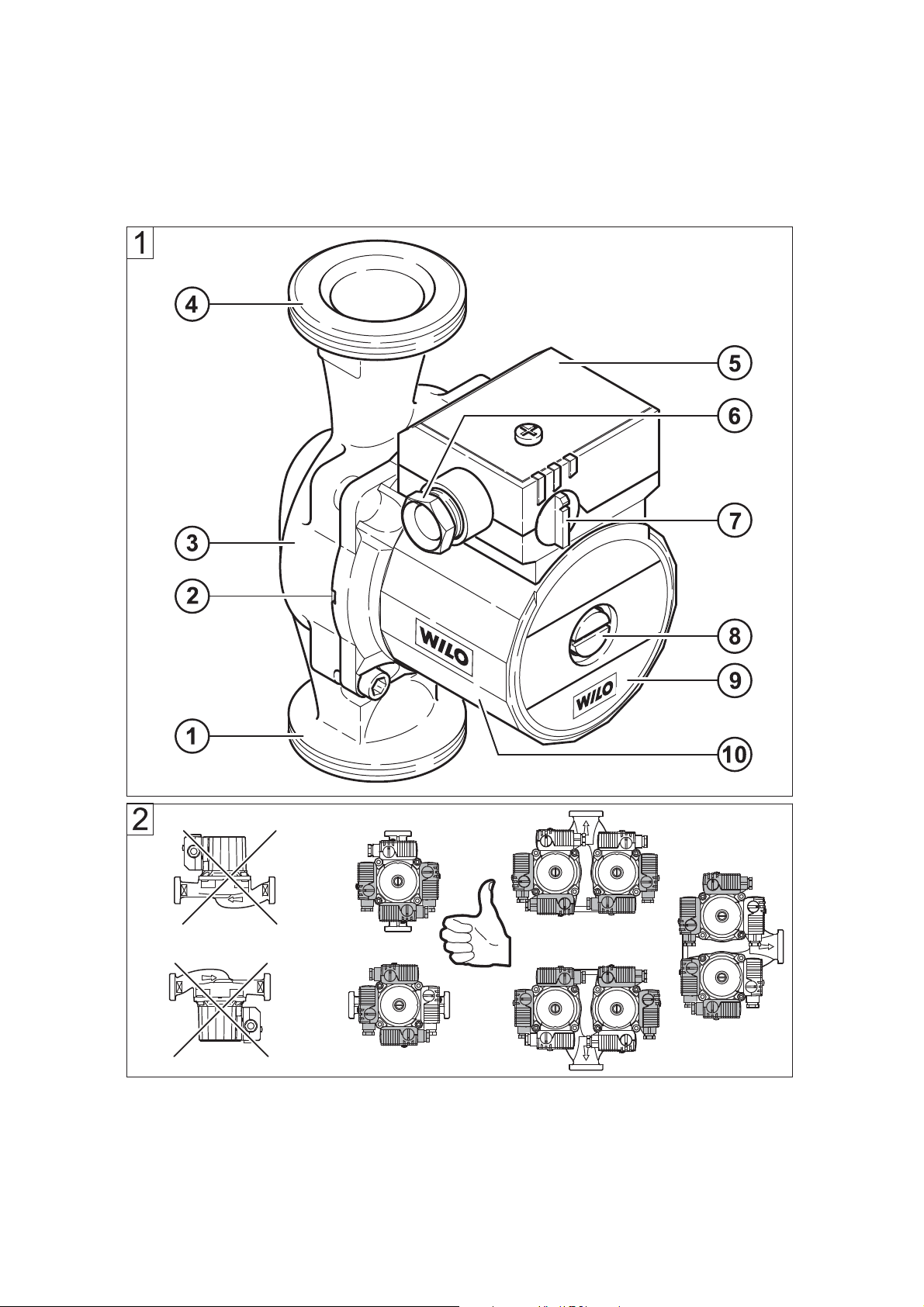
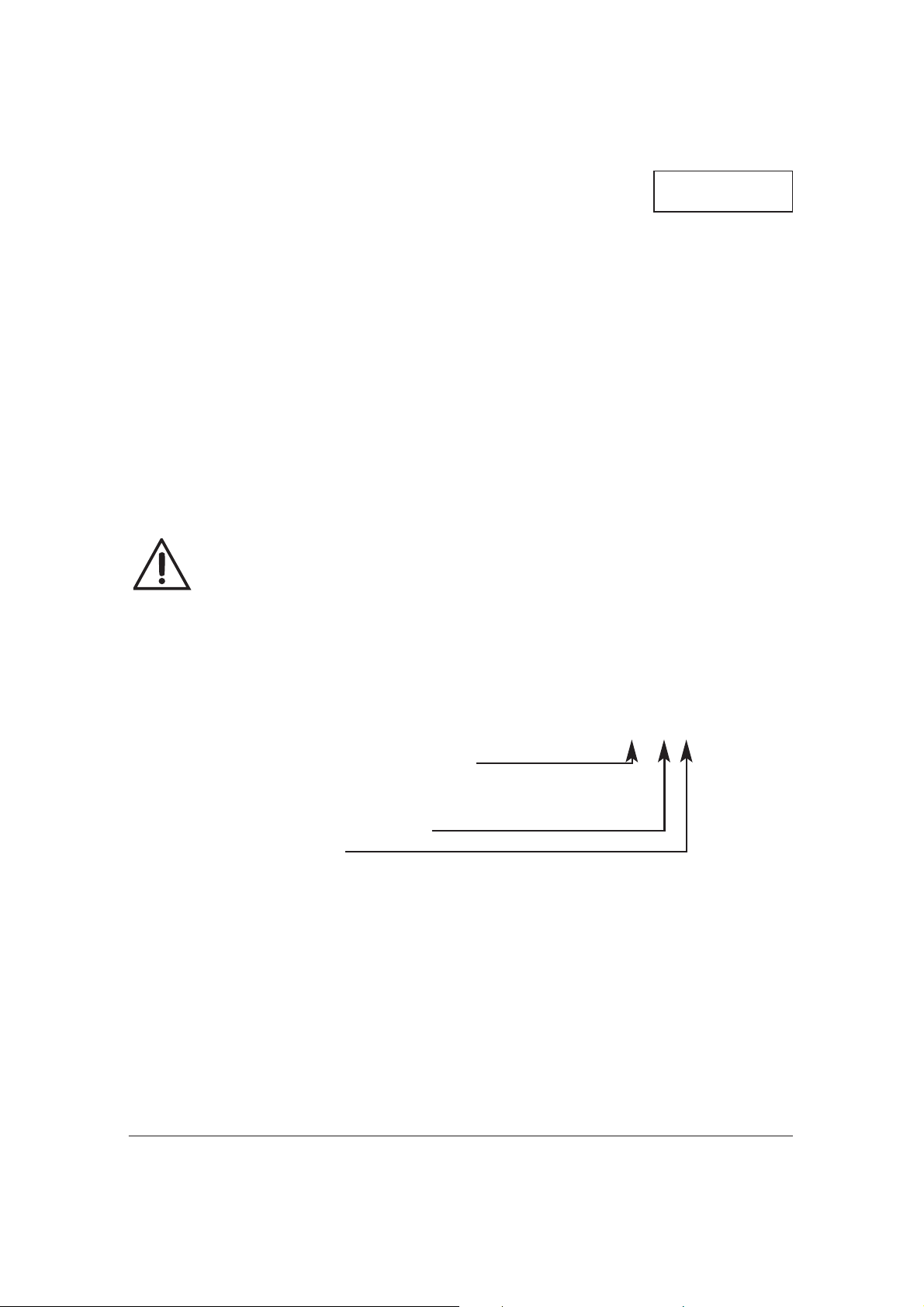
Terms (Fig. 1)
1 Suction joint
2 Condensate outlet
3 Pump housing
4 Pressure joint
5 Terminal box
6 Cable entry
7 Speed switch
8 Ventilation
9 Rating plate
10 Motor housing
Connection and electrical data
Voltage: 1~230V ±10%
Mains frequency: 50Hz
Power consumption
P
max: Rating plate
Motor speed, max.: Rating plate
Protection
category IP: Rating plate
Speed setting: 3 stages
Fitting length: 130/180 mm
Perm. operating
pressure, max.: 10 bar
Perm. medium
temperatures
min./max.: -10/+110 °C
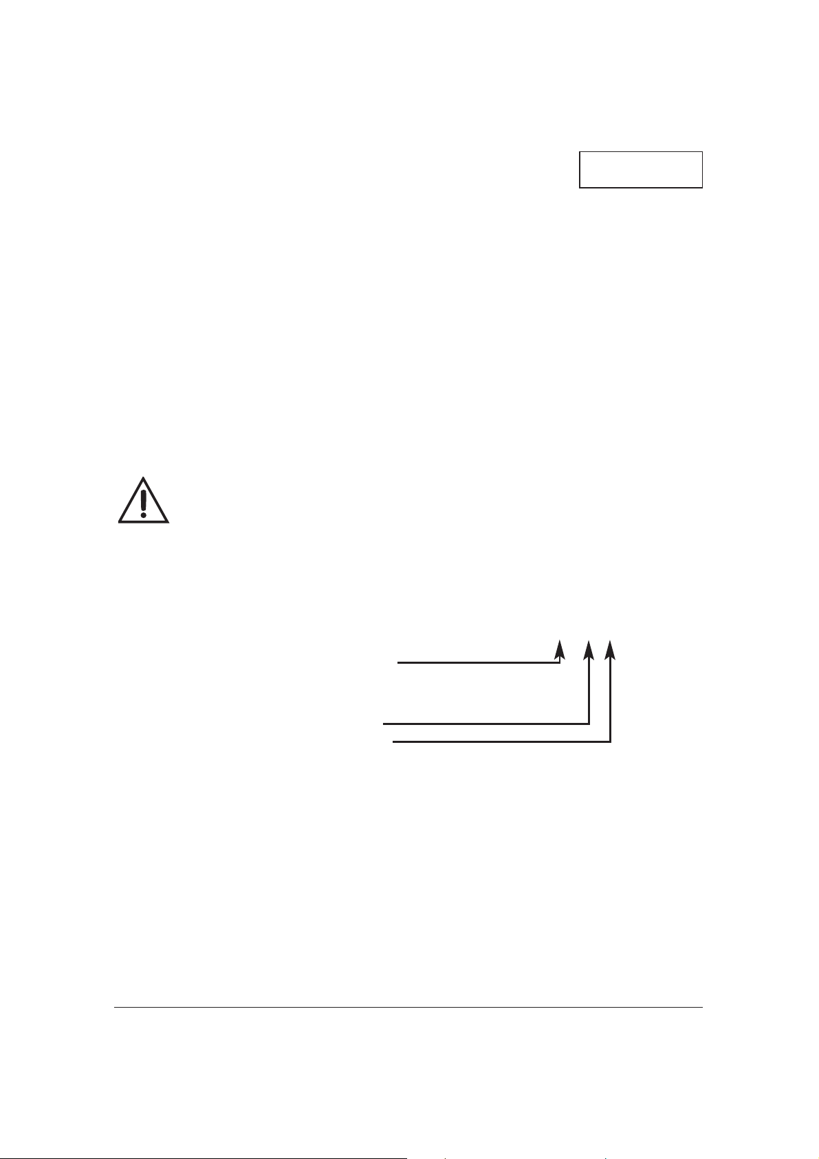
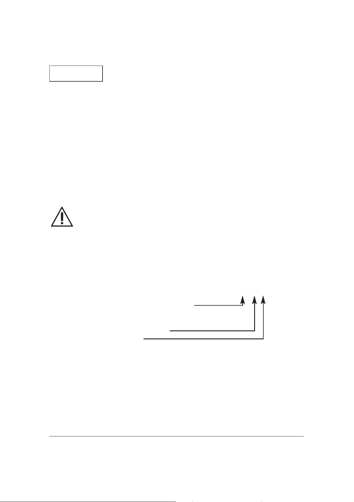
Rating plate Star-RS 30/4
Heating circulating pumps,
glandless pumps
RS
Screwed pipe pump
Nominal width [mm]
15, 20 (Rp1/2), 25 (Rp1), 30 (Rp11/4)
Maximum delivery head [m]
Page 9
8
ENGLISH
Perm. ambient
temperatures max.: +40 °C
Min. inlet pressure* at suction side at
+ 50 °C: 0.05 bar
+ 95 °C: 0.3 bar
+ 110 °C: 1.0 bar
* The values are valid up to 300 m
above sea level. For higher elevations add: 0.01 bar/100 m.
The minimim inlet pressure must be
maintained in order to avoid cavitation noise!
Permissible fluids:
– Heating water acc. to VDI 2035
– Water and water/glycol mixtures in
a ratio up to 1:1. Glycol mixtures
require a reassessment of pump
hydraulic data in line with the
increased viscosity and depending
on mixing ratios. Only approved
makes of additives with corrosion
inhibitors must be used in strict
compliance with manufacturers'
instructions.
– For use of other kinds of fluids con-
sult WILO first.
2 Safety
These instructions contains basic
reference which must be strictly adhered. It is therefore imperative for the
installer and operator to carefully read
these instructions prior to installation
and commissioning.
Please observe, not only the safety
directions under the main heading
„safety rules“, but also those added
and specially marked under the
ensuing headers.
Safety marks contained in these
instructions
Safety rules contained herein which, if
not complied with, may be dangerous
to persons are specially highlighted by
the following danger symbols:
Danger from electrical causes:
Safety references which, if not complied with, may cause damage to the
pump / installation or impair its functions are highlighted by the word:
Staff training
The personnel installing the pump /
unit must have the appropriate qualifications for this work.
Dangers from non-observance of
safety rules
Non-observance of safety reference
may cause personal injury or damage
to the pump or installation. Failure to
comply with the safety references
could invalidate warranty and/or
damage claims.
In particular, non-compliance may, for
example, cause the following dangerous situations:
– Failure of important pump or unit
functions,
– Causing personal injury due to
electrical or mechanical causes.
ATTENTION!
Page 10

9
ENGLISH
Safety rules for the operator
Local regulations for the prevention of
accidents must be observed.
Dangers caused by electrical energy
must be excluded. Local or general
regulations [e.g. IEC, VDE, etc.] and
directives from local energy supply
companies are to be followed.
Safety rules for inspection and
installation work
The operator must ensure that all inspection and installation work is carried out by authorised and qualified
specialists who have carefully studied
these instructions.
Work on the pump/unit must be carried out only with the machine switched off and at compete standstill.
Unauthorized modification and
manufacture of spare parts
Alterations to the pump or installation
may only be carried out with the
manufacturer's agreement.
The use of original spare parts and
accessories authorised by the manufacturer will ensure safety. The use of
any other parts may invalidate claims
invoking the liability of the manufacturer for any consequences.
Unauthorised operating methods
The operating safety of the pump or
installation supplied can only be guaranteed if it is used in accordance
with paragraph 1 of the operating
instructions. Under no circumstances
should the limit values given in the
data sheet be exceeded.
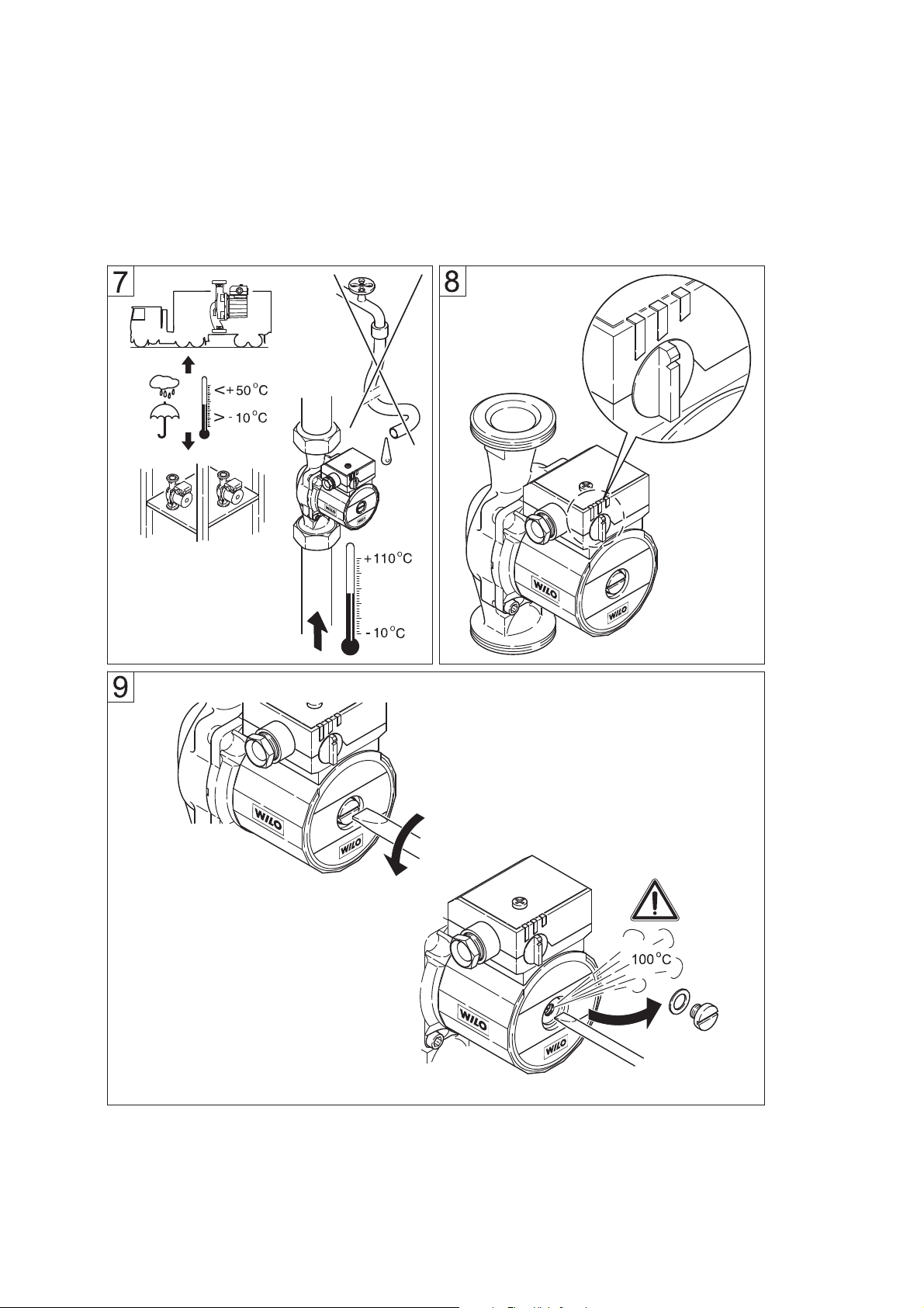
3 Transport/Interim
storage
The pump contains
electronic components
and must be protected
against moisture from
outside and mechanical damage (shock /
im pact) (Fig. 7). It must
not be exposed to temperatures outside the
range -10 °C to +50 °C.
(Fig. 7).
4 Description of
pump/accessories
Products delivered
– Complete pump
– 2 flat gaskets,
– Installation and operating in -
structions
Pump description
In the wet-running pump all rotating
parts are surrounded by the flow
medium, including the motor rotor.
A shaft seal, which would be subject
to wear and tear, is not required. The
pumping medium lubricates the friction bearing and cools both bearing
and rotor.
No
motor overload protection
is
required.
Even the maximum overload current
cannot damage the motor. The motor
operates non-overloading.
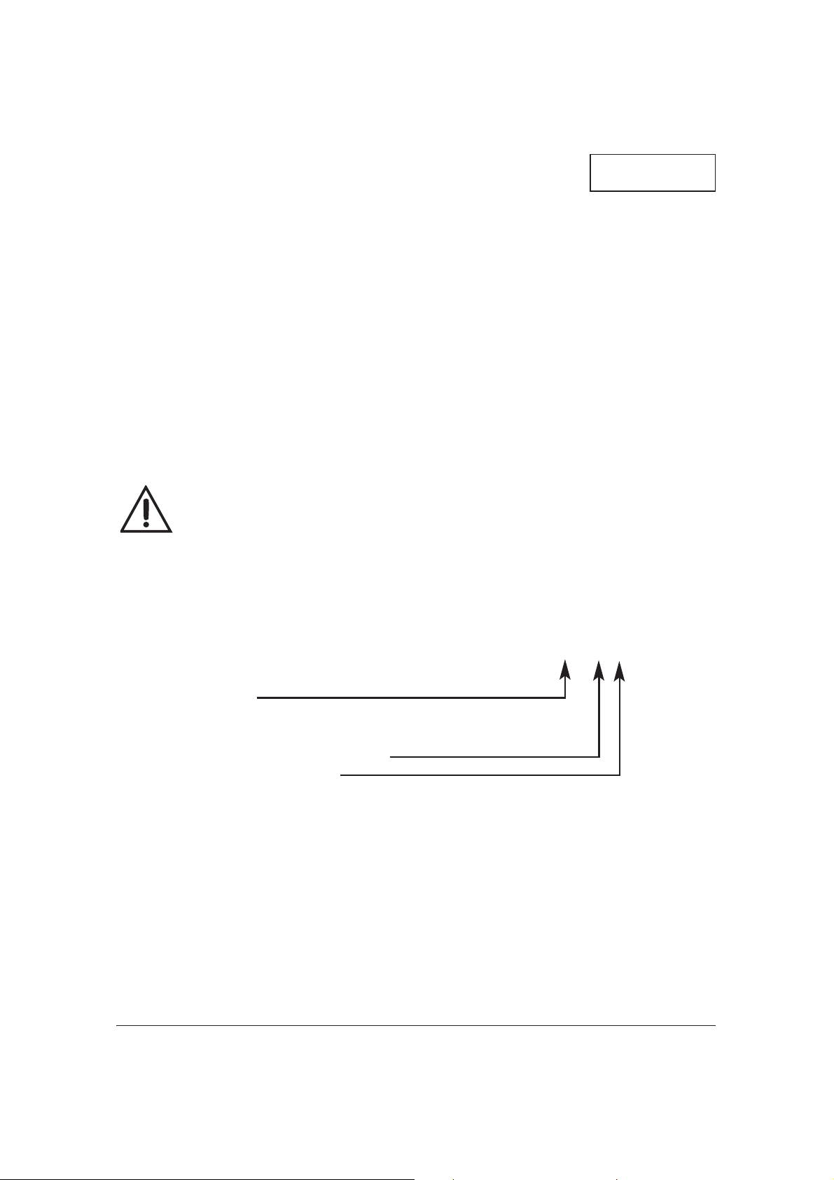
Speed setting (Fig. 8)
The speed of the pump can be adjusted with a 3-position rotary button. In
ATTENTION!
Page 11
10
ENGLISH
position 3 the speed is approx.
40...50 % of the maximum speed with
the power consumption being reduced to 50 %.
Accessories
Accessories must be ordered separately.
– Inserts for the pipe connection of
the screwed-pipe pump.
5 Assembly/
Installation
Installation
Installation and service by qualified personnel only!
– Assembly should only take place
once all welding and soldering
work and the rinsing of the pipe
network has been completed. Dirt
can have an adverse effect on the
functioning of the pump.
– The pump must be installed in an
easily accessible position to facilitate inspection or replacement.
– It is recommended that shut-off
devices be fitted before and after
the pump. This will save having to
drain and refill the system if the
pump needs replacing. The fittings
are to be installed so that any water
that escapes cannot drip onto the
pump motor or terminal box.
– When installed into the flow pipe of
an open-vented system, the open
safety vent must be connected to
the system on the inlet side of the
pump.
– Pump to be mounted with the shaft
in the horizontal plane in such a
way that it is not stressed by the
pipework. (Installation positions in
Fig. 2).
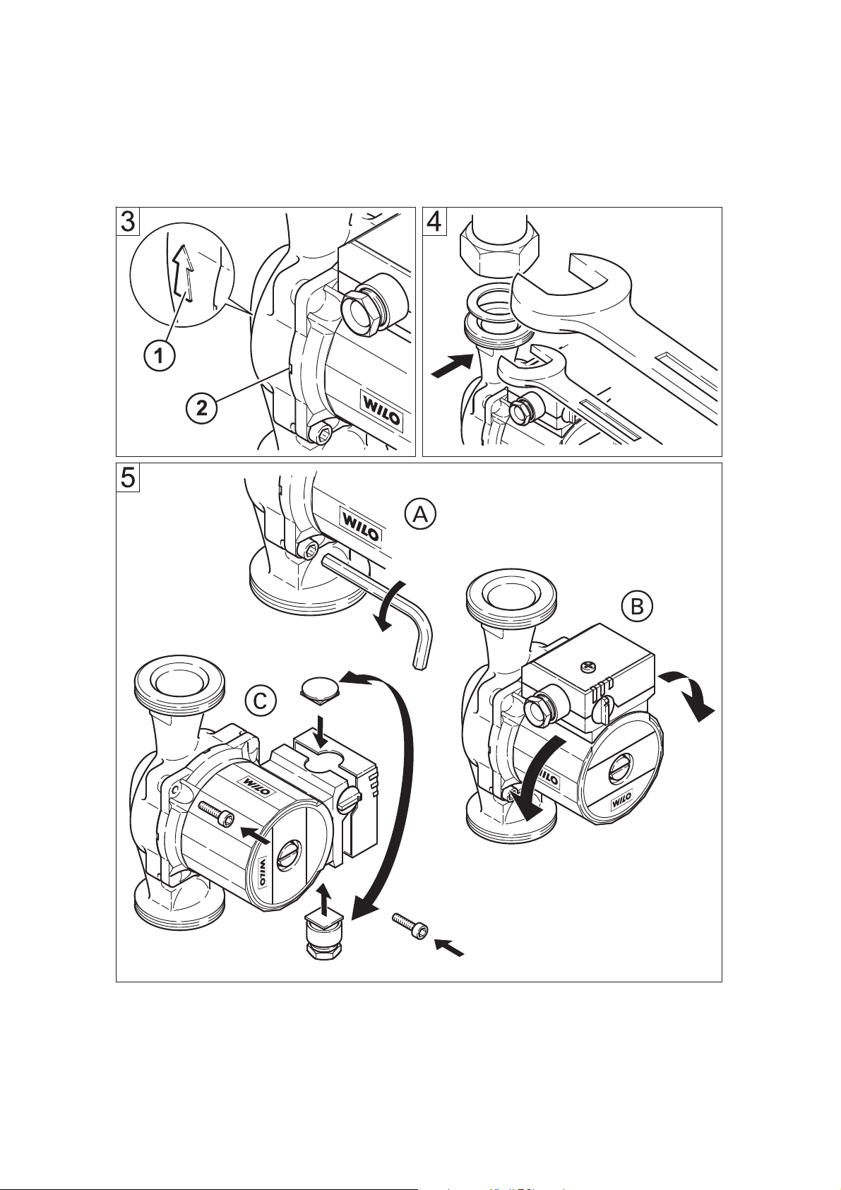
– An arrow on the pump casing indi-
cates the direction of flow (Fig. 3,
pos.1).
– Secure the pump against twisting
by using a spanner (Fig. 4).
– In order to attain the correct termi-
nal box position the motor housing
can be turned once the motor
fastening screws have been losened (Fig. 5).
Do not damage the flat
gasket. If necessary
use a new gasket:
Ø 86 x Ø 76x2.0 mm EP.
For units which are to
be insulated, only the
pump housing may be
insulated. The motor
and condensate openings must remain free
(Fig. 3, pos. 2).
Electrical connection
Electrical connection must be
carried out by a qualified and
licensed electrician in strict
conformity to ruling national
conditions and local regulations (e.g. VDE regulations in
Ger many).
– According to Part 1 of the VDE 0730,
the pump must be connected to the
electrical supply by a solid wire
equipped with a plug connection or
an all-pole switch. The width of the
contact gap must be at least 3 mm.
ATTENTION!
ATTENTION!
ATTENTION!
Page 12
11
ENGLISH
– To guarantee protection against
dripping water and the strain relief
of the PG screwed joint, a connecting cable of suitable external diameter is to be used (e.g. H 05 VV-F
3 G 1.5).
– When using the pump in units
where the water temperature
exceeds 90 °C, a connecting cable
with corresponding heat resistance
must be used.
– The supply cable must be laid in
such a way that it never touches the
pipework and/or the pump and
motor casing.
– Check that the mains current and
voltage comply with the data on the
rating plate.
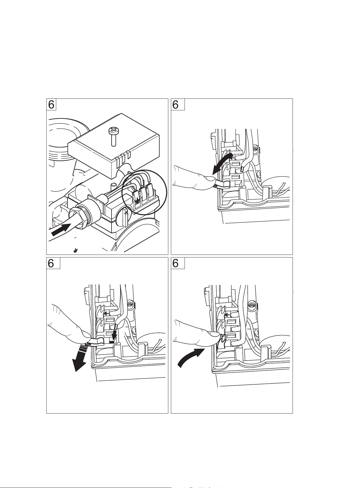
– Make mains connection as shown
in Fig. 6.
– The connecting cable can be fed
through the PG screwed joint either
to the left or right. If necessary, the
blind plug and PG screwed joint are
to be exchanged. If the terminal box
is positioned on the side, always
insert the PG screwed joint from
below (Fig. 5)
Caution risk of short-circuit!
After electrical connections
the terminal box cover must
be closed properly, to protect
against moisture.
– Pump/installation must be earthed
in compliance with regulations.
– When connecting automatic switch-
gear (for double pumps), follow the
appropriate Installation and
Operating Instructions.
6 Operation
System filling and venting
The pump may need venting e.g. if the
heating and pump are working but the
heating element remains cold. If there
is air in the pump chamber, the pump
will not pump water.
Carefully fill the unit with water.
The pump is normally vented automatically after a short operatinal period.
Short-term dry running will not damage the pump. If it becomes necessary
to vent the pump, please observe the
following procedure:
– Switch off pump,
Risk of burning if the pump
is touched!
Depending on the operating
condition of the pump and/or
installation (fluid temperature)
the pump/mo tor can become
very hot.
– Close the valve on the discharge
side.
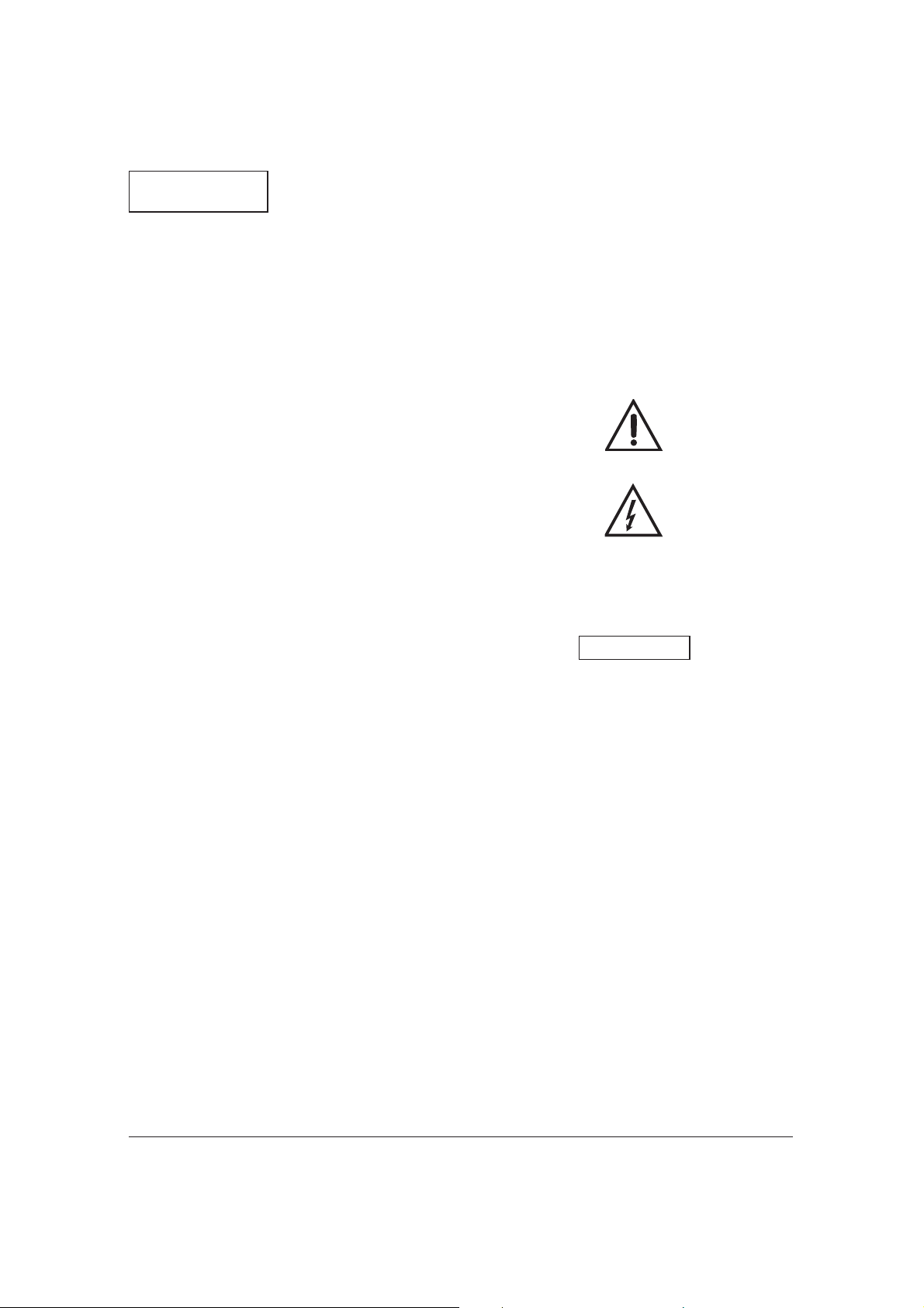
Risk of scalding!
Depending on the fluid temperature and the sys tem pressure, if the vent screw is completely loosened hot liquid or
vapour can escape or even
shoot out at high pressure.
– Carefully loosen and fully remove
the vent plug with a suitable
screwdriver (Fig. 9).
– Carefully push pump shaft back
several times with screwdriver.
– Protect all electrical parts against
the leaking water.
– Switch-on pump.
Page 13
12
Subject to technical alterations!
ENGLISH
It is possible that the
pump blocks with the
vent plug open, de pending on the sys tem
pressure.
– After 15...30 s tighten the vent plug.
– Re-open isolating valve,
Speed setting
If the rooms cannot be sufficiently
heated, the speed of the pump may be
too low. In this case you will need to
switch to a higher speed.
If, on the other hand, the pump is set
at too high a speed, flow noise may
occur in the lines and in particular at
throttled thermostatic valves. This can
be rectified by switching to a lower
speed.
The speed is changed by means of
a rotary button at the terminal box.
3 represents the lowest and 1 the
highest speed.
7 Maintenance
Prior maintenance or repair
work switch off the pump and
secure against unauthorized
switching.
8 Problems, Causes
and Remedies
Motor is switched on but fails to
run:
– Check electrical fuses,
– Check voltage of pump (observe
rating plate data),
– Check capacitor size (observe
rating plate data!).
– Motor is blocked, e.g. by deposits
from the heating water.
– Remedies: Fully remove vent plug,
check and if necessary rectify free
running of pump rotor by turning
the slotted end of the shaft with a
screwdriver (Fig. 9).
At high water temperatures
and system pressure close
isolating valves before and
after the pump. First, allow
pump to cool down
Noisy pump operation
– Cavitation due to insufficient inlet
pressure.
– Remedies: increase system pressu-
re within the permissible range.
– Check speed setting, if necessary
switch to a lower speed.
If the fault cannot be rectified,
contact your nearest WILO
Customer Service.
9 Spare parts
All rating plate data must be stated
when ordering spare parts.
ATTENTION!
Page 14
13
FRANÇAIS
1 Généralités
Dans cette notice, nous vous présentons les fonctions et l'utilisation de la
pompe déjà installée. Les photos mentionnées dans le texte figurent sur le
volet précédent.
Utilisation réglementaire
La pompe de circulation (dénommée
ci-après " pompe " ou de manière
générale " installation ") est conçue
pour véhiculer les fluides dans les
tuyauteries.
Ne pas utiliser la pompe
pour véhiculer de l'eau potable
ou des produits alimentaires.
Les principales applications
sont les suivantes :
– la circulation d'eau de chauffage
(divers systèmes)
– les boucles industrielles de circulati-
on d'eau chaude
Notions (fig. 1)
1 Tubulure d'aspiration
2 Écoulement de la condensation
3 Corps de pompe
4 Tubulure de refoulement
5 Boîtes à bornes
6 Guide-câble
7 Commutateur de vitesse
8 Dégazage
9 Plaque signalétique
10 Carcasse moteur
Plaque signalétique Star-RS 30/4
Circulateur de chauffage, rotor noyé
RS
Pompe à raccord vissé
Diamètre nominal de la tuyauterie [mm]
15, 20 (Rp
1
/2), 25 (Rp1), 30 (Rp11/4)
Hauteur manométrique maximale [m]
Raccordement et puissance
Tension: Mono 230V ±10%
Fréquence
réseau : 50Hz
Puissance
absorbée
P
max: Plaque signalétique
Vitesse de rotation
moteur maxi : Plaque signalétique
Type de
protection IP : Plaque signalétique
Modification de
la vitesse : 3 vitesses
Entraxe : 130/180 mm
Pression maxi
admissible : 10 bars
Page 15
14
FRANÇAIS
Températures
de fluides
admissibles
minimale/
maximale : -10/+110 °C
Température
ambiante maxi
admissible : +40 °C
Charge minimale à l'aspiration* à
+ 50 °C : 0,05 bar
+ 95 °C : 0,3 bar
+110 °C : 1,0 bar
* Ces valeurs sont données pour une
altitude de 300 m au-dessus de la
mer (majorer de 0,01 bar pour une
élévation de 100 m).
La pression mini à l'aspiration doit
être respectée pour éviter les risques de cavitation.
Liquides véhiculés :
– eau de chauffage selon VDI 2035
– eau et mélange eau/glycol en
dosage jusqu'à 1:1. En cas d'ajouts
de glycol, corrigez les valeurs de
refoulement de la pompe suivant la
viscosité supérieure, en fonction du
dosage en pourcentage. N'utilisez
que des produits de marques dotés
d'inhibiteurs de protection contre la
corrosion ; respectez les consignes
du fabricant.
– En cas d'utilisation d'autres fluides,
l'autorisation de WILO est requise.
2 Sécurité
La présente notice contient des
instructions primordiales, qui doivent
être respectées lors du montage et de
la mise en service. C'est pourquoi elle
devra être lue attentivement par le
monteur et l'utilisateur et ce, impérativement avant le montage et la mise en
service.
Il y a lieu d'observer non seulement
les instructions générales de cette
section, mais aussi les prescriptions
spécifiques abordées dans les points
suivants.
Signalisation des consignes
Les consignes de sécurité contenues
dans cette notice qui, en cas de nonobservation, peuvent représenter un
danger pour les personnes, sont symbolisées par le symbole suivant :
En cas de danger électrique, le symbole indiqué est le suivant :
Les consignes de sécurité dont la
non-observation peut représenter un
danger pour l'installation et son fonctionnement sont indiquées par le
signe :
Qualification du personnel
Il convient de veiller à la qualification
du personnel amené à réaliser le
montage.
Dangers encourus en cas de nonobservation des consignes
La non-observation des consignes de
ATTENTION!
Page 16

15
FRANÇAIS
sécurité peut constituer un danger
pour les personnes, la pompe ou l'installation. Elle peut également entraîner la suspension de tout recours en
garantie.
Plus précisément, les dangers encourus peuvent être les suivants:
– défaillance de fonctions importan-
tes de l'installation ou de la pompe
– danger pour les personnes en cas
de dysfonctionnement électrique et
mécanique de la machine
Consignes de sécurité pour l'utilisateur
Il convient d'observer les consignes
en vue d'exclure tout risque d'accident.
Il y a également lieu d'exclure tous
dangers liés à l'énergie électrique.
Respectez les instructions de la
norme NFC 15.100 et des normes
européennes.
Conseils de sécurité pour les travaux d'inspection et de montage
L'utilisateur doit faire réaliser ces travaux par une personne spécialisée
qualifiée ayant pris connaissance du
contenu de la notice.
Les travaux réalisés sur la pompe ou
l'installation ne doivent avoir lieu que
si les appareillages correspondants
sont à l'arrêt.
Modification du matériel et utilisation de pièces détachées non
agréées
Toute modification de la pompe ou de
l'installation ne peut être effectuée que
moyennant l'autorisation préalable du
fabricant.
L'utilisation de pièces de rechange
d'origine et d'accessoires autorisés
par le fabricant garantit la sécurité.
L'utilisation d'autres pièces peut dégager notre société de toute responsabilité.
Modes d'utilisation non autorisés
La sécurité de fonctionnement de la
pompe ou de l'installation livrée n'est
garantie que si les prescriptions précisées au § 1 de la notice d'utilisation
sont respectées. Les valeurs indiquées dans la fiche technique ne doivent en aucun cas être dépassées.
3 Transport et stockage
La pompe contient des
composants électroniques et doit être
protégée contre l'humidité ainsi que les dommages mécaniques
provoqués par des
chocs ou des coups
(figure 7). La pompe ne
peut être soumise à
des températures infé rieures à -10 °C et
supérieures à +50 °C
(figure 7).
ATTENTION!
Page 17

16
FRANÇAIS
4 Description de la
pompe et de ses
accessoires
Étendue de la fourniture
– pompe complète
– 2 joints plats
– notice de montage et de mise en
service
Description de la pompe
Dans une pompe à rotor noyé, l'ensemble des parties tournantes, y compris le rotor du moteur, baignent dans
le liquide pompé.
Une étanchéité de l'arbre soumis à l'usure n'est pas nécessaire. Le fluide
véhiculé lubrifie le palier lisse et refroidit palier et rotor.
Une
protection du moteur
n'est pas
nécessaire.
Même le courant de surcharge maximal ne peut endommager le moteur, le
moteur résiste au courant de blocage.
Modification de la vitesse
(figure 8)
Les trois vitesses de la pompe peuvent être modulées grâce à un bouton
tournant. La vitesse mini (3) est de 40
à 50 % inférieure à la vitesse maxi, ce
qui réduit la consommation de 50 %
environ.
Accessoires
Les accessoires disponibles sont à
commander séparément.
– inserts de tuyauterie pour les pom-
pes à raccord-unions
5 Installation/Montage
Montage
L'installation et la
mise en service
devront être réalisées uniquement
par du personnel
qualifié !
– Le montage devra être réalisé après
avoir terminé toutes les opérations
de soudage et de brasage et, le cas
échéant, le nettoyage de la tuyauterie. La saleté peut entraver le fonctionnement correct de la pompe.
– Installez la pompe dans un endroit
facile d'accès pour permettre toute
intervention ultérieure (contrôle/permutation).
– Il est recommandé d'installer des
vannes d'isolement en amont et en
aval de la pompe. Ceci évitera de
vidanger l'installation lors du remplacement de la pompe. On orientera les vannes de façon à éviter
que les fuites d'eau ne tombent sur
le moteur de la pompe ou la boîte à
bornes.
– En cas de montage dans le conduit
d'aspiration d'installations ouvertes,
le conduit d'aspiration de sécurité
doit dériver avant la pompe.
– Réalisez le montage hors tension,
avec l'arbre de la pompe positionné
horizontalement (po sitions de montage en fig. 2).
– La flèche sur le corps de pompe
indique le sens d'écoulement du
fluide (fig. 3, pos. 1).
– Protégez la pompe contre les torsi-
ons à l'aide d'une clé plate (figure 4).
ATTENTION!
Page 18
17
FRANÇAIS
– Pour raccorder la boîte à bornes, il
convient de tourner la carcasse
moteur après avoir dévissé les vis
de fixation du moteur (figure 5).
Veillez à ne pas endommager le joint plat. Le
cas échéant, utilisez un
nouveau joint :
Ø 86 x
Ø 76 x 2.0 mm EP.
Si l'on isole l'installation,
seul le corps de la
pompe doit être isolé. Le
moteur et les orifices
d'écoulement de condensation doivent rester
libres (figure 3, pos. 2).
Raccordement électrique
Le raccordement électrique
doit être effectué par un électricien agréé, conformément
aux prescriptions locales
en vigueur (par exemple
NFC 15 .100 et normes européennes).
– Le raccordement électrique doit
être réalisé selon la norme
NFC 15.100 ou normes européennes via un câble électrique fixe
pourvu d'un commutateur ou d'un
contacteur multipolaire avec au
moins 3 mm de plage d'ouverture
de contact.
– Pour assurer la protection de
l'installation contre les gouttes
d'eau et le soulagement de traction
du guide-câble, utilisez un câble
de raccordement avec un
diamètre extérieur suffisant (p. ex.
H 05 VV-F 3 G 1,5).
– Pour des applications avec des
liquides supérieurs à 90°C, il convient d'utiliser un câble de raccordement résistant à la chaleur.
– Le câble de raccordement doit être
placé de façon à ne jamais entrer
en contact avec la canalisation
principale et/ou le corps de pompe
et la carcasse moteur.
– La nature du courant et la tension
d'alimentation doivent correspondre
aux indications figurant sur la plaque signalétique.
– Réalisez le raccordement au réseau
selon la figure 6.
– Le câble de raccordement peut,
au choix, être dirigé vers la
gauche ou vers la droite via le
guide-câble. Le tampon borgne et le
guide-câble doivent être remplacés
si nécessaire. Lorsque la boîte à
bornes est positionnée sur le côté,
veillez toujours à introduire le guidecâble par le bas (figure 5).
Attention risque de court
circuit !
Après raccordement électrique, refermer le capot suivant
normes en vigueur et afin
d'éviter toute humidité dans le
bornier.
– La pompe/l'installation doivent être
mises à la terre conformément aux
prescriptions.
– Pour le raccordement d'appareilla-
ges électriques automatiques (pour
les pompes doubles), reportez-vous
à la notice de montage et de mise
en service correspondante.
ATTENTION!
ATTENTION!
Page 19
18
FRANÇAIS
6 Mise en service
Remplissage et dégazage
Il convient de purger la pompe lorsque les radiateurs restent froids en
dépit du bon fonctionnement du
chauffage et de la pompe. En effet,
lorsque le boîtier de la pompe est
rempli d'air, cette dernière ne refoule
pas d'eau.
Remplissez l'installation d'eau.
Normalement, le dégazage du rotor
de la pompe s'effectue automatiquement après une brève période de
fonctionnement. Un bref fonctionnement à sec n'endommage pas
la pompe. Si le dégazage du rotor
s'avère nécessaire, procédez de la
sorte :
– arrêtez la pompe
Danger de brûlure au con tact de la pompe!
En fonction des conditions de
fonctionnement de la pompe ou
de l'installation (température du
fluide), la pompe/le moteur peut
devenir extrêmement chaud.
– fermez la vanne d'aspiration
Danger de brûlure!
Selon la température du fluide
et la pression du système, lorsqu'on ouvre la vis de dégazage, du fluide brulant peut
s'échapper sous forme liquide
ou gazeuse ou sortir à haute
pression lors de l'ouverture de
la vis de dégazage.
– dévissez complètement la vis de
dégazage à l'aide d'un tournevis
adapté (fig. 9)
– repoussez prudemment à plusieurs
reprises l'arbre de la pompe à l'aide
d'un tournevis
– évitez que des fuites de liquide ne
se répandent sur les parties électriques
– enclenchez la pompe
Si la pression dans
l'installation est im portante, la pompe
peut se bloquer lorsque la vis de dégazage
est ouverte.
– au bout de 15 à 30 sec., refermez la
vis de dégazage
– ouvrez à nouveau la vanne d'arrêt
Modification de la vitesse
Si la vitesse de rotation est trop faible,
la température des locaux à chauffer
seratrop faible également, dans ce
cas, il faut augmenter la vitesse de
rotation de la pompe.
Si, à l'inverse, la pompe est réglée sur
une vitesse de rotation trop élevée,
des bruits d'écoulement se font entendre dans la tuyauterie, et en particulier
au niveau des robinets thermostatiques. On résout ce problème en
passant à une vitesse de rotation
inférieure.
Un bouton tournant situé sur la boîte à
bornes permet de moduler les vitesses. Le chiffre 3 représente la vitesse
mini, le chiffre 1 la vitesse maxi.
ATTENTION!
Page 20
19
FRANÇAIS
7 Entretien
Avant toute intervention ou
arrêt, mettre les pompes hors
tension et s'assurer contre
toute remise en route intempestive.
8 Pannes, causes et
remèdes
La pompe ne tourne pas (alors
qu'elle est alimentée en courant) :
– vérifiez les fusibles
– vérifiez la tension de la pompe (res-
pectez la plaque signa létique)
– vérifiez la capacité du condensateur
(respectez la plaque signalétique)
– le moteur est bloqué (par ex. à cause
d'un dépôt de résidus en suspension)
– Solution : dévissez complètement la
vis de dégazage et débloquez le
rotor au moyen d'un tournevis en
tournant l'extrémité fendue de l'arbre (figure 9).
Si la température de l'eau et
la pression du système sont
élevées, fermez les vannes
d'arrêt situées en amont et en
aval de la pompe et laissez
refroidir la pompe avant d'effectuer cette opération.
La pompe fait du bruit
– Cavitation en raison d'une pression
insuffisante à l'aspiration.
– Solution : augmentez la pression
d'admission du système dans la
limite autorisée.
– Contrôlez la vitesse; si nécessaire
passez à une vitesse inférieure.
S'il n'est pas possible de remédier
au défaut, veuillez faire appel au
S.A.V. WILO le plus proche.
9 Pièces détachées
Lors de toute commande de pièces
détachées, il convient de mentionner
toutes les données de la plaque signalétique.
Sous réserve de modifications techniques!
Page 21
20
NEDERLANDS
Aansluitgegevens en prestaties
Spanning: 1~230V ±10%
Netfrequentie: 50Hz
Vermogenopname
P
max: typeplaatje
Motortoerental, max.: typeplaatje
Beschermingsklasse IP: typeplaatje
Omschakeling
toerental: 3 trappen
Inbouwlengte: 130/180mm
Typeplaatje Star-RS 30/4
Verwarmingscirculatiepomp, natlopermotor
RS
Pomp met schroefaansluiting
Nom. aansluitmaat [mm]
15, 20 (Rp
1
/2), 25 (Rp1), 30 (Rp11/4)
Maximale opvoerhoogte [m]
1 Algemeen
In deze handleiding gaan we in op de
werking en de bediening van de pomp
in klaar geïnstalleerde toestand. De
afbeeldingen waarnaar in de tekst
wordt verwezen staan in de tekst op
de voorste binnenflap.
Gebruik overeenkomstig het doel
De circulatiepomp (hierna gewoon
pomp of installatie geheten) dient voor
het opvoeren van vloeistoffen in buissystemen.
De pomp mag niet worden
gebruikt voor drinkwater of
levensmiddelen. De voornaamste toepassingsgebieden zijn:
– Verwarmingsinstallaties met warm
water, diverse systemen,
– Industriële, gesloten circulatiesyste-
men.
Begrippen (afb. 1)
1 Zuigzijde
2 Condensafvoer
3 Pomphuis
4 Perszijde
5 Aansluitkast
6 Kabeldoorvoer
7 Toerenkeuzeschakelaar
8 Ontluchting
9 Typeplaatje
10 Motorhuis
Page 22
21
NEDERLANDS
Max. toegelaten
bedrijfsdruk: 10 bar
Toeg. mediumtemperaturen minimaal/maximaal: -10/+110°C
Toeg. omgevingstemperatuur: maximaal:
+40 °C
Min. aanvoerdruk* aan de zuigzijde bij
+ 50 °C: 0,05 bar
+ 95 °C: 0,3 bar
+ 110 °C: 1,0 bar
* Deze waarden gelden tot op 300 m
boven de zeespiegel; toeslag voor
hogere lagen: 0,01 bar/100 m hoogte-toename.
Om cavitatiegeluid te vermijden
moet worden gelet op de minimale
aanvoerdruk aan de zuigzijde van
de pomp!
Pompvloeistoffen:
– Verwarmingswater volgens
VDI 2035,
– Water- en water-glycolmengsels in
mengverhoudingen tot 1:1. Bij het
bijmengen van glycol zijn de opvoergegevens van de pomp, overeenkomstig de hogere viscositeit,
afhankelijk van de procentuele
mengverhouding te corrigeren.
Gebruik alleen merkartikelen met
corrosiebeschermende middelen.
Houd u aan de aanwijzingen van de
producent.
– Bij gebruik van andere vloeistoffen
is goedkeuring door WILO noodzakelijk.
2 Veiligheid
Deze handleiding bevat belangrijke
aanwijzingen die bij de montage en de
in bedrijfname nageleefd moeten worden. Daarom moeten de monteur en
de bevoegde gebruiker deze handleiding beslist lezen voor de montage en
de in bedrijfname.
Men dient niet alleen te letten op de
onder dit hoofdstuk "Veiligheid"
genoemde algemene veiligheidsvoorschriften, maar ook op de hierna aangegeven speciale veiligheidssymbolen.
Veiligheidssymbolen
De in deze handleiding opgenomen
veiligheidssymbolen, die bij niet-naleving tot gevaar voor personen kunnen
leiden, zijn aangegeven met het algemene gevaarsymbool:
en bij gevaar
voor elektrische spanning met
Bij veiligheidsvoorschriften, die bij
het niet naleven ervan gevaar opleveren voor de pomp/installatie en haar
werking, staat de volgende aanduiding:
OBGELET!
Page 23

22
NEDERLANDS
Personeelskwalificatie
De montage dient door gekwalificeerd
personeel te worden uitgevoerd.
Gevaren bij het niet in acht nemen
van de veiligheidsvoorschriften
De niet-naleving kan gevaar voor personen en de installatie opleveren.
De niet-naleving van de veiligheidsvoorschriften kan ertoe leiden dat iedere
aanspraak op schadeloosstelling vervalt.
Concreet kan niet-naleving de volgende gevaren inhouden:
– Uitvallen van belangrijke functies
van de pomp/installatie,
– Verwonding van personen door
elektrische en mechanische inwerking,
Veiligheidsvoorschriften voor de
gebruiker
De bestaande voorschriften ter voorkoming van ongevallen dienen in acht
te worden genomen.
Gevaar door elektrische energie moet
worden voorkomen. Er moet worden
gehandeld conform de algemene
voorschriften [vb. IEC, VDE, enz.] en
de voorschriften van het plaatselijke
energie-bedrijf.
Veiligheidsvoorschriften voor inspectie- en montagewerkzaamheden
De gebruiker dient er voor zorgen dat
alle inspectie- en montagewerkzaamheden worden uitgevoerd door erkend
en gekwalificeerd vakpersoneel, dat
zich door het aandachtig lezen van de
handleiding voldoende heeft geïnformeerd.
In principe mogen werkzaamheden
aan de pomp/installatie alleen bij stilstand worden uitgevoerd.
Eigenhandige ombouw en vervaardiging van onderdelen
Veranderingen aan de
pomp/installatie zijn alleen in overleg
met de fabrikant toegestaan.
In het kader van de veiligheid mag
enkel gebruik worden gemaakt van
originele onderdelen en door de fabrikant toegelaten toebehoren. De fabrikant kan niet aansprakelijk worden
gesteld voor de gevolgen die voortvloeien uit het gebruik van andere
onderdelen.
Ontoelaatbare bedrijfsomstandigheden
De bedrijfszekerheid van de geleverde
pomp/installatie is alleen gewaarborgd bij een doelgerichte toepassing,
conform deel 1 van de handleiding.
De in het datablad aangegeven grenswaarden mogen in geen geval worden
overschreden.
3 Transport/
Tussenopslag
De pomp bevat elektronische onderdelen en
moet worden be schermd
tegen vocht en mechanische be schadigingen
(stof/slagen) (afb. 7). De
pomp mag niet worden
blootgesteld aan temperaturen lager dan -10°C
en hoger dan + 50°C
(afb. 7).
OBGELET!
Page 24

23
NEDERLANDS
4 Beschrijving
pomp/toebehoren
Leveringsomvang
– pomp,
– 2 stuks vlakke pakking,
– inbouw- en gebruikshandleiding.
Beschrijving van de pomp
Bij een natlopende pomp zijn alle
draaiende delen door het medium
omgeven, ook de rotor van de motor.
Een aan slijtage onderhevige asafdichting ontbreekt. De pompvloeistof
smeert en koelt het glijlager en de
rotor.
Een
motorbeveiliging
is niet noodzakelijk.
Zelfs de maximale overbelastingsstroom kan de motor niet beschadigen. De motor is bestand tegen blokkeerstromen.
Toerental-omschakeling (afb. 8)
Het toerental van de pomp kan met
een draaiknop op drie standen worden ingesteld. Het toerental in stap 3
bedraagt ca. 40...50 % van het maximaal toerental terwijl de stroomopname met 50 % afneemt.
Toebehoren
Beschikbare toebehoren moeten
afzonderlijk worden besteld,
– Inlegstukken voor de buisaansluit-
ing van de schroefpomp.
5 Montage en
bediening
Montage
Inbouw en in gebruik
nemen alleen door
vakpersoneel
– De pomp mag pas worden inge-
bouwd na het voltooien van alle lasen soldeerwerkzaamheden, en het
eventueel noodzakelijke spoelen
van het leidingstelsel. Vuil kan de
pomp onklaar maken.
– De pomp op een goed toegankeli-
jke plaats monteren, zodat later
controleren of vervangen makkelijk
kan worden uitgevoerd.
– Het inbouwen van afsluitkranen
voor en achter de pomp is aanbevolen. Dit bespaart het legen en
opnieuw vullen van de hele installatie bij een eventuele vervanging van
de pomp. De kranen moeten zodanig worden ge plaatst, dat er geen
lekwater op de motor van de pomp
of de aansluitkast kan druppelen.
– Bij de inbouw in open installaties
dient veiligheidsvoorloop (open
expansievat) in de toevoerleiding
voor de pomp op het leidingstelsel
worden aangesloten.
– De montage spanningsvrij uitvoeren
met horizontaal liggende motor
(voor inbouwposities, zie afb. 2).
– De pijl op het pomphuis geeft de
stromingsrichting aan (afb. 3, pos.1).
– De pomp met een passende
steeksleutel tegen verdraaien blokkeren (afb. 4).
OBGELET!
Page 25
24
NEDERLANDS
– Na het lossen van de motorbevesti-
gingsschroeven kan het motorhuis,
voor het positioneren van het aansluitkastje, in het pomphuis worden
verdraaid (afb. 5).
De vlakke pakking niet
beschadigen. Gebruik
evt. een nieuwe pakking:
Ø 86 x Ø 76x 2.0 mm EP.
Bij installaties die voorzien worden van isolatie,
mag alleen het pomphuis geïsoleerd worden.
De motor en de condens-afvoeropeningen
moeten vrij blijven (afb. 3,
pos.2).
Elektrische aansluiting
De elektrische aansluiting
dient door een plaatselijk
erkende elektro-installateur
overeenkomstig de geldende
voorschriften te worden uitgevoerd.
– De elektrische aansluiting moet vol-
gens de geldende voorschriften
worden uitgevoerd. Bij de toepassing van een meerpolige schakelaar moet de contactopening minimaal 3 mm zijn.
– Om zeker te zijn van de bescher-
ming tegen druppelwater en de trekontlasting, moet de aansluitkabel
van voldoende diameter worden
gebruikt (vb. H 05 VV-F 3 G 1,5).
– Bij gebruik van de pomp in installa-
ties met watertemperaturen, hoger
dan 90 °C, moet een geschikte,
warmtebestendige aansluitkabel
worden gebruikt.
– De aansluitkabel moet zodanig wor-
den gelegd dat deze in geen geval
in aanraking komt met het leidingwerk, pomp- of motorhuis.
– De stroomsoort en de spanning van
de netaansluiting moeten overeenstemmen met de gegevens op het
typeplaatje.
– De netaansluiting overeenkomstig
afb. 6 uitvoeren.
– De aansluitkabel kan naar keuze
links of rechts door een wartel worden
gevoerd. Blinddoppen en wartels zijn
voor dat doeleinde evt. uit te wisselen. Bij zijdelingse plaatsing van het
aansluitkastje altijd de kabeltoevoer
van onder af voorzien (afb. 5)
Voorzichtig, gevaar voor
kortsluiting!
Voor de bescherming tegen
vocht moet het deksel van de
klemmenkast, na de elektrische aansluiting, weer volgens de voorschriften worden
gesloten.
– De pomp aarden volgens de voor-
schriften.
– Voor de aansluiting van automa-
tisch werkende schakelapparaten
(voor dubbelpompen) verwijzen wij
naar de betreffende inbouw- en
gebruikshandleiding.
6 In bedrijfname
Vullen en ontluchten
De installatie naar behoren vullen en
ontluchten. Ontluchting van het pomprotorhuis volgt zelfstandig al na een
korte gebruiksduur. Kort stondig droo-
OBGELET!
OBGELET!
Page 26
25
NEDERLANDS
glopen schaadt de pomp niet.
Indien het ontluchten van de motorruimte noodzakelijk is dient men als
volgt te handelen.
– De pomp uitschakelen,
Verbrandingsgevaar bij het
aanraken van de pomp!
Naargelang de bedrijfstoestand van de pomp resp. de
installatie (temperatuur van
de pompvloeistof) kan de
hele pomp zeer heet worden.
– Leiding aan de afvoerzijde afsluiten.
Verbrandingsgevaar!
Naargelang de druk en de
temperatuur van de pompvloeistof kan er bij het openen van de ontluchtingsschroef hete pompvloeistof in
vloeibare of dampvormige
toestand vrijkomen resp.
onder hoge druk ontsnappen.
– De ontluchtingsschroef voorzichtig
met een schroevendraaier lossen
en helemaal uitdraaien (afb. 9).
– De pomp-as meerdere keren met
een schroevendraaier terugschuiven,
– elektrische delen beschermen
tegen uitstromend water,
– de pomp inschakelen.
De pomp kan bij een
geopende ontluch tingsschroef, afhankelijk van
de hoogte van de werkdruk, blokkeren.
– Na 15...30 s de ontluchtingsschroef
terug indraaien.
– Kraan terug openen.
Veranderen van toerental
Indien de ruimtes onvoldoende worden verwarmd, kan het toerental van
de pomp te laag zijn. In dat geval is
overschakelen naar een hoger toerental noodzakelijk.
Is de pomp daarentegen op een te
hoog toerental ingesteld, dan ontstaan
in de leidingen en speciaal in thermostaatventielen stromingsgeluiden.
Ze zijn te verhelpen door overschakelen naar een lager toerental.
De omschakeling naar een ander toerental gebeurt met behulp van een draaiknop in het aansluitkastje. 3 staat voor
het laagste, 1 voor het hoogste toerental.
7 Onderhoud
Voor onderhoud- of reparatiewerkzaamheden pomp spanningsvrij schakelen en tegen
onbevoegd inschakelen beveiligen.
8 Storingen, oorzaken
en oplossingen
De pomp loopt niet bij ingeschakelde stroomtoevoer:
– De elektrische zekeringen controleren.
– De spanning aan de pomp contro-
leren (let op de gegevens van het
typeplaatje),
– De grootte van de condensator
nagaan (let op het typeplaatje!).
– De motor is geblokkeerd, bijvoor-
beeld door afzetting van verontreinigingen in het verwarmingswater.
– Oplossing: ontluchtingsschroef voll-
OBGELET!
Page 27
26
NEDERLANDS
edig uitdraaien en de pomprotor
met behulp van een schroevendraaier déblokkeren door het verdraaien van de pompas. Om dit
mogelijk te maken is de pompas
voorzien van een gleuf (afb. 9).
Bij hoge watertemperaturen
en systeemdrukken de afsluitkranen voor en achter de
pomp sluiten. De pomp eerst
laten afkoelen.
– Bij cavitatie door een onvoldoende
aanvoerdruk.
– Remedie: Bij cavitatiegeluiden door
een ontoereikende aanvoerdruk, de
systeemdruk binnen de toegestane
grenzen verhogen.
– De instelling van het toerental con-
troleren, eventueel overschakelen
naar een lager toerental.
Indien de bedrijfsstoring niet kan
worden verholpen wendt u zich tot
de dichtstbij gelegen WILO-servicedienst.
9 Onderdelen
Bij het bestellen van onderdelen dienen alle gegevens van het typeplaatje
te worden opgeven.
Technische wijzigingen voorbehouden!
Page 28
27
ITALIANO
1 Generalità
In questo manuale d'istruzione sono
spiegate le funzioni e i comandi della
pompa dopo che è stata installata ed
è pronta per l'uso. Le figure richiamate
nel testo si trovano nelle pagine anteriori del manuale.
Utilizzo conforme del prodotto
La pompa di circolazione (in seguito
chiamata semplicemente pompa) è
utilizzata per il pompaggio di liquidi in
un sistema di tubazioni.
Non utilizzare la pompa per
acqua potabile o liquidi per
alimenti.
Le applicazioni principali sono:
– Riscaldamento ad acqua calda,
sistemi vari,
– Sistemi di circolazione industriali
(circuiti chiusi).
Definizioni (figura 1)
1 Bocca aspirante
2 Scarico condensato
3 Corpo pompa
4 Bocca premente
5 Morsettiera
6 Ingresso cavi
7 Selettore velocità
8 Sfiato
9 Targhetta dati
10 Corpo motore
Chiave di lettura Star-RS 30/4
Pompa di circolazione a rotore bagnato
RS
= Pompa a bocchettoni
Diametro nominale bocche [mm]
15, 20 (Rp
1
/2), 25 (Rp1), 30 (Rp11/4)
Prevalenza massima [m]
Caratteristiche tecniche e
prestazioni
Tensione: 1~230V ±10%
Frequenza: 50Hz
Potenza assorbita
P
max: Targhetta dati
Massimo numero
giri: Targhetta dati
Grado di protezione
IP: Targhetta dati
Commutazione
velocità: 3 velocità
Page 29
28
ITALIANO
Interasse di
montaggio: 130/180 mm
Max. pressione di
esercizio: 10 bar
Campo temperatura fluido: min./max.:
-10/+110 °C
Temperatura
ambiente: max.: +40 °C
Min. pressione* sulla bocca aspirante
a
+ 50 °C: 0,05 bar
+ 95 °C: 0,3 bar
+ 110 °C: 1,0 bar
* I valori si valgono fino a 300 m sul
livello del mare; per altitudini maggiori, aggiungere: 0,01 bar/100 m di
altezza.
Per evitare rumori di cavitazione
mantenere la minima pressione
sulla bocca aspirante della pompa.
Fluidi pompati:
– Acqua di riscaldamento secondo
VDI 2035
– Miscele di acqua e glicole in rap-
porto massimo di 1:1. Con l'aggiunta di glicole, le prestazioni della
pompa devono essere corrette a
causa della maggiore viscosità
dipendente dalla percentuale della
miscela. Usare solo prodotti di
marca con inibitori anti-corrosione.
Rispettare scrupolosamente le
istruzioni del produttore.
– Per utilizzare altri fluidi richiedere
l'autorizzazione scritta di WILO.
2 Sicurezza
Le presenti istruzioni contengono
informazioni fondamentali ai fini del
corretto montaggio e uso del prodotto.
Devono essere lette e rispettate scrupolosamente sia da chi esegue il
montaggio sia dall'utente finale.
Oltre al rispetto delle norme di sicurezza in generale, rispettare tutti i punti
specificamente e specialmente contrassegnati nel presente manuale.
Contrassegni utilizzati nelle
istruzioni
In questo manuale sono inserite informazioni e prescrizioni contrassegnate
con simboli.
Il mancato rispetto delle prescrizioni di
sicurezza contrassegnate col simbolo
di
attenzione pericolo
possono essere fonte di pericolo per
l'incolumità delle persone e integrità
delle cose.
Il mancato rispetto delle prescrizioni di
sicurezza contrassegnate con la parola
possono essere fonte di pericolo per
l'incolumità delle persone e integrità
delle cose.
Page 30

29
ITALIANO
Il mancato rispetto delle prescrizioni
di sicurezza contrassegnate con la
parola
possono
essere fonte di pericolo per l'integrità
e funzionalità delle apparecchiature e
delle macchine.
Qualifica del personale
Il personale che installa la pompa
deve possedere la qualifica appropriata al tipo di lavoro.
Pericoli conseguenti al mancato
rispetto delle prescrizioni di
sicurezza
Il mancato rispetto delle prescrizioni di
sicurezza, oltre a mettere in pericolo le
persone e danneggiare le apparecchiature, farà decadere ogni diritto
alla garanzia.
Le conseguenze della inosservanza
delle prescrizioni di sicurezza possono essere:
– mancata attivazione di alcune fun-
zioni del prodotto o sistema,
– pericolo alle persone conseguenti a
eventi elettrici e meccanici.
Informazioni sulla sicurezza per
l'utente
Applicare e rispettare tutte le prescrizioni antinfortunistiche.
Il personale addetto al montaggio e
all'esercizio dell'impianto è tenuto al
rispetto delle presenti istruzioni, a tutte
le norme e leggi vigenti in materia
(CEE, CEI, VVFF, UNI, ecc.).
Informazioni sulla sicurezza per il
montaggio e l'ispezione
È preciso compito del committente
assicurare che le operazioni di montaggio, ispezione e manutenzione
siano eseguite da personale autorizzato e qualificato e che abbia letto
attentamente le presenti istruzioni.
Tutti i lavori sulle apparecchiature e
macchine vanno eseguiti in condizione di riposo.
Modifiche e parti di ricambio
Qualsiasi modifica alle apparecchiature, macchine o impianti deve essere
preventivamente concordata e autorizzata dal costruttore. Le parti di ricambio originali e gli accessori autorizzati
dal costruttore sono parte integrante
della sicurezza delle apparecchiature
e delle macchine. L'impiego di componenti o accessori non originali può
pregiudicare la sicurezza e farà decadere la garanzia.
Condizioni di esercizio non
consentite
La sicurezza di funzionamento della
pompa/sistema è assicurata solo per
le applicazioni e le condizioni descritte
nel capitolo 1 del manuale. I valori
limite indicati nei fogli tecnici/catalogo
sono vincolanti e non devono essere
superati per nessun motivo.
ATTENZIONE!
Page 31

30
ITALIANO
3 Trasporto e
magazzinaggio
La pompa contiene
componenti elettronici che devono essere
protetti contro l'umidità e il danneggiamento meccanico
(urti / colpi) durante il
magazzinaggio (fi gura 7).La pompa
non deve essere sottoposta a temperature fuori dal campo di
-10 °C fino a +50 °C.
4 Descrizione della
pompa/accessori
Fornitura
– Pompa completa
– 2 guarnizioni piatte,
– Istruzioni di montaggio, uso e
manutenzione
Descrizione della pompa
Nella pompa a rotore bagnato tutte le
parti rotanti sono immerse nel fluido
pompato, anche il rotore del motore.
La tenuta dell'albero, normalmente
soggetta ad usura, non è necessaria.
Il fluido pompato lubrifica e raffredda
le boccole di supporto e il rotore.
La
protezione del motore
non è
necessaria.
La massima corrente di sovraccarico
non può danneggiare il motore. Il
motore è auto-protetto.
Commutazione delle velocità
(figura 8)
La velocità della pompa può essere
commutata manualmente con il
pulsante rosso a 3 posizioni. Nella
posizione 3, la velocità è circa il
40...50 % della velocità massima, con
la riduzione della potenza assorbita a
50 %.
Accessori
Ordinare gli accessori separatamente.
– Bocchettoni per il collegamento
della pompa alle tubazioni.
5 Montaggio/
Installazione
Montaggio
Montaggio e messa
in servizio solo da
personale qualificato!
– Eseguire il montaggio solo alla fine
delle operazioni di saldatura, brasatura e dopo aver pulito a fondo le
tubazioni dell'impianto. La presenza
di corpi estranei e sporcizia possono danneggiare irrimediabilmente la
pompa.
– Per facilitare le operazioni di manu-
tenzione e sostituzione, in stallare la
pompa in luogo facilmente accessibile.
– Si consiglia il montaggio di organi
d'intercettazione prima e dopo la
pompa. In caso di smontaggio della
pompa non sarà necessario vuotare e riempire nuovamente l'impianto. Installare i rubinetti d'intercettazione in modo che l'acqua non goc-
ATTENZIONE!
ATTENZIONE!
Page 32
31
DEUTSCHITALIANO
cioli sul motore o sulla morsettiera
della pompa.
– In caso di montaggio della pompa
sulla mandata di impianti con vaso
d'espansione aperto, verificare che
il tubo di sicurezza si trovi sulla
bocca aspirante della pompa.
– Effettuare il montaggio privo di ten-
sioni meccaniche e con l'albero
rotore in posizione orizzontale
(posizioni di montaggio in figura 2).
– Una freccia sul corpo pompa indica
la direzione del flusso (figura 3,
posizione 1).
– Durante il serraggio del bocchetto-
ne tenere saldo il corpo pompa con
una chiave fissa (figura 4).
– Nel caso si renda necessaria la
modifica della posizione della morsettiera, ruotare il corpo del motore
nella posizione desiderata, dopo
aver allentato le viti di fissaggio del
motore (figura 5).
Non danneggiare la
guarnizione di tenuta.
Grandezza guarnizione:
Ø 86 x Ø 76 x
2.0 mm EP.
Per gli impianti che
devono essere isolati,
tenere presente che
può essere isolato
soltanto il cor po
pompa, il motore e le
aperture di scarico
del condensato devono ri manere libere
(fi gura 3, posizione 2).
Collegamenti elettrici
I collegamenti elettrici de vono
essere eseguiti da una ditta
installatrice qualificata ed
essere conformi alle norme
CEI, EN.
– Collegare la pompa alla rete elettri-
ca tramite un cavo a posa fissa
(VDE 0730 parte 1), munito di presa
e spina, oppure di interruttore onnipolare con distanza minima fra i
poli di almeno 3 mm.
– Per assicurare la protezione contro
l'ingresso dell'acqua e la resistenza
alla trazione attraverso il pressacavo PG, utilizzare cavi con diametro sufficiente (per esempio,
H 05 VV-F 3 G 1,5).
– Con l'utilizzo della pompa in impi-
anti con temperatura dell'acqua
oltre 90 °C, utilizzare un cavo di collegamento resistente al calore.
– Posare il cavo di alimentazione in
modo che non tocchi mai le tubazioni, il corpo pompa e/o corpo
motore.
– Il tipo di rete elettrica e la tensione
devono essere conformi a quanto
indicato nella targhetta della
pompa.
– Effettuare i collegamenti alla rete
come indicato in figura 6.
– Il cavo di collegamento può essere
introdotto nella morsettiera tramite il
pressacavo PG sia da destra sia da
sinistra. In relazione all'esecuzione,
il pressacavo PG e il tappo devono
essere scambiati fra loro. Se la
morsettiera è posizionata sul lato,
inserire sempre il pressacavo PG
da sotto (Fig. 5)
ATTENZIONE!
ATTENZIONE!
Page 33

32
ITALIANO
Attenzione pericolo di cortocircuito!
Per proteggere dall'umidità,
dopo avere terminato i collegamenti elettrici, chiudere con
cura il coperchio morsettiera.
– Collegare la pompa/impianto al
conduttore di terra, secondo le
norme CEI (EN) vigenti.
– In caso di utilizzo dell'apparecchio
di comando per pompe gemellari
(pompe doppie) fare riferimento alle
istruzioni di montaggio specifiche.
6 Messa in servizio
Riempimento e sfiato
Lo sfiato della pompa è richiesto
quando, per esempio, il riscaldamento
e la pompa funzionano ma i corpi
scaldanti restano freddi. Con la presenza di aria nel corpo pompa, la
pompa non pomperà acqua.
Riempire correttamente l'impianto con
acqua.
Lo sfiato del vano rotore della pompa
di norma avviene automaticamente
dopo un breve tempo di funzionamento della pompa. Il breve funzionamento
a secco non danneggerà la pompa.
Nel caso sia necessario lo spurgo
manuale dell'aria, procedere come
segue:
– Spegnere la pompa,
Toccando la pompa esiste
il pericolo di ustioni!
A seconda della condizione di
funzionamento della pompa e/o
dell'impianto (temperatura del
fluido), tutta la pompa può
diventare molto calda.
– Chiudere la linea sul lato di scarico.
Attenzione pericolo di
ustioni!
In relazione alla pressione del
sistema idraulico e alla temperatura del fluido pompato,
questi può essere bollente e
fuoriuscire, sotto forma liquida o di vapore con forte
getto, quando la vite di spurgo è lenta.
– Allentare con un cacciavite adatto e
rimuovere con cautela completamente il tappo di spurgo (figura 9).
– Spingere diverse volte delicatamen-
te con il cacciavite l'albero all'indietro,
– Proteggere tutti i componenti elettri-
ci contro l'ingresso di acqua,
– Accendere la pompa.
In relazione alla pressione operativa
dell'impianto, è pos
sibile che la pompa si
blocchi quando il
tappo di spurgo è
stato tolto.
– Dopo 15...30 secondi, stringere il
tappo di spurgo.
– Riaprire i rubinetti d'intercettazione,
Variazione manuale della velocità
Se i locali non sono sufficientemente
riscaldati, la velocità della pompa potrebbe essere troppo bassa. In questo
caso, occorre passare ad una velocità
superiore.
ATTENZIONE!
Page 34

33
ITALIANO
Se invece la velocità impostata è troppo alta, possono verificarsi rumori di
flusso nelle tubazioni, in particolare
nelle valvole termostatiche. È possibile
eliminare il problema passando ad
una velocità minore.
La variazione della velocità si effettua
con il pulsante rosso presente sulla
morsettiera. Il N° 3 rappresenta la
velocità minima, 1 quella massima.
7 Manutenzione
Prima di procedere a qualsiasi operazione di manutenzione o ripristino togliere tensione alla pompa e assicurarsi
che non possa essere accesa
da terze persone.
8 Blocchi, cause e
rimedi
Il motore è acceso ma non
funziona:
Controllare i fusibili,
– Verificare la tensione sulla pompa
(confrontare con i dati di targa!),
– Verificare la capacità del conden-
satore (confrontare con i dati di
targa!).
– Il motore è bloccato, per esempio
da depositi dell'acqua riscaldata.
– Rimedi: rimuovere completamente il
tappo di spurgo, controllare e, se
necessario, ruotare il rotore della
pompa girando l'estremità dell'albero con un cacciavite (figura 9).
Con acqua ad alta temperatura e alta pressione
nell'impianto, chiudere gli
organi d'intercettazione
prima e dopo la pompa e
lasciare raffreddare.
La pompa è rumorosa
– Cavitazione dovuta alla pressione
sulla bocca aspirante insufficiente:
– Rimedio: aumentare la pressione
dell'impianto nell'ambito dei valori
consentiti.
– Controllare l'impostazione della
velocità; se necessario, passare ad
una velocità minore.
Quando, nonostante tutto, non si è
in grado di eliminare la causa della
guasto rivolgersi all'installatore
idraulico o al Centro Assistenza
Wilo più vicino.
9 Parti di ricambio
Assieme all'ordine per parti di ricambio, fornire tutti i dati della targhetta.
Con riserva di modifica!
Page 35

34
ESPAÑOL
1 Generalidades
En estas instrucciones se presentan
las funciones y el uso de la bomba
una vez instalada. Las fotos a las que
el texto hace referencia aparecen en
la hoja desplegable delantera.
Utilización reglamentaria
La bomba circuladora (de ahora en
adelante denominada „bomba“ o, en
general, „instalación“) está di señada
para bombear líquidos en tuberías.
No utilice la bomba para
bombear agua potable o productos alimenticios.
Las principales aplicaciones son:
– Calefacción por agua caliente,
sistemas diversos,
– Sistemas industriales de circula-
ción de agua caliente en circuito
cerrado.
Elementos (fig. 1)
1 Boca de aspiración
2 Orificio de evacuación de conden-
sados
3 Carcasa de la bomba
4 Boca de impulsión
5 Caja de bornes
6 Prensaestopas PG
7 Conmutador de velocidad
8 Purga
9 Placa de características
10 Carcasa del motor
Claves del tipo Star-RS 30/4
Bomba circuladora de calefacción, rotor húmedo
RS
Bomba roscada
Diámetro nominal de la tubería [mm]
15, 20 (Rp
1
/2), 25 (Rp1), 30 (Rp11/4)
Altura máxima de impulsión [m]
Datos de conexión y prestaciones
Tensión: 1~230V ±10%
Frecuencia de red: 50Hz
Potencia absorbida Pmáx:
véase placa de características
Velocidad máx. del motor:
véase placa de características
Tipo de protección IP:
véase placa de características
Conmutación de velocidad:
3 velocidades
Page 36

35
ESPAÑOL
Medida longitudinal para el
montaje: 130/180 mm
Presión máxima admisible:
10 bares
Temperaturas de trabajo
(mín./máx.): -10/+110 °C
Temperatura máx. ambiente:
+40 °C
Presión mínima de entrada* a
+ 50 °C: 0,05 bares
+ 95 °C: 0,3 bares
+ 110 °C: 1,0 bares
* Estos valores corresponden a una
altura de 300 m por encima del
nivel del mar, para altitudes superiores hay que añadir 0,01 bares por
cada 100 m adicionales.
La presión mínima de entrada en la
boca de aspiración debe respetarse para evitar los ruidos de cavitación.
Medios de impulsión:
– Agua de calefacción según
VDI 2035,
– Agua y mezcla agua/glicol en un
porcentaje de hasta 1:1. En caso
de añadirse glicol, los datos de
impulsión de la bomba deben corregirse según la viscosidad, superior en función de la dosificación en
porcentaje. Utilice sólo productos
de marcas con inhibidores de corrosión. Res pete siempre estrictamente las instrucciones del fabricante.
– En caso de que se utilicen otros
líquidos, debe obtenerse la autorización de WILO.
2 Seguridad
Las instrucciones contienen información fundamental acerca de las medidas de seguridad que se deben adoptar a la hora de la instalación y de la
puesta en marcha. Por ello, es imprescindible que tanto el instalador como
el usuario lean las instrucciones antes
de pasar al montaje y la puesta en
marcha.
Además de la información general
contenida en este apartado, también
deben tenerse en cuenta las advertencias específicas que se exponen
en los apartados que siguen.
Símbolos
Las advertencias que, en caso de
incumplimiento, implican peligro para
las personas están señaladas con el
símbolo:
En caso de aviso relativo a la tensión
eléctrica, el símbolo indicado es el
siguiente:
Las instrucciones de seguridad cuyo
incumplimiento puede suponer un
peligro para la bomba/instalación y su
funcionamiento están señaladas con
la palabra
¡ATENCIÓN!
Page 37

36
ESPAÑOL
Cualificación del personal
El personal que se encargue del
montaje debe poseer las cualificaciones requeridas para este tipo de
trabajo.
Peligros en caso de incumplimiento de las advertencias
El incumplimiento de las advertencias
de seguridad puede implicar un grave
riesgo para las personas y para el
aparato. A su vez, puede tener como
consecuencia la pérdida de todo
derecho a indemnización por daños
ocasionados (garantía).
El incumplimiento puede traer consigo, entre otros, los siguientes peligros:
– La suspensión de funciones impor-
tantes.
– Riesgos para las personas por
contacto con tensión eléctrica o
con accionamientos mecánicos.
Advertencias para el usuario
Se deben respetar las normas vigentes para la prevención de accidentes.
También debe excluirse cualquier
posibilidad de entrar en contacto
con tensión eléctrica. Deben respetarse las instrucciones de las directivas locales o generales (p.ej. UNE,
IEC, etc.) así como las de la compañía
local de suministro de electricidad.
Advertencias para trabajos de
montaje y mantenimiento
Al usuario le incumbe la responsabilidad de encargar la inspección y el
montaje a un especialista autorizado y
cualificado que con ozca bien las presentes in strucciones.
Cualquier trabajo que se lleve a cabo
en el aparato exige su previa desconexión.
Modificaciones y repuestos no
autorizados
Cualquier modificación que se pretenda efectuar en la bomba o instalación
requiere la previa autorización del
fabricante.
Los repuestos originales y los accesorios autorizados por el fabricante sirven para garantizar una mayor seguridad. El fabricante queda eximido de
toda responsabilidad por los daños
ocasionados por repuestos o accesorios no autorizados.
Funcionamiento indebido
Un funcionamiento seguro de la
bomba o instalación sólo se garantiza
bajo cumplimiento y respeto de lo
expuesto en el apartado 1 de las
instrucciones de instalación y funcionamiento. Los valores indicados en la
hoja de características técnicas no
deben excederse en ningún caso.
3 Transporte y
almacenamiento
La bomba contiene componentes electrónicos
y debe protegerse de
la humedad exterior y
de los daños mecánicos provocados por los
choques o los golpes
(fig. 7).
¡ATENCIÓN!
Page 38

37
ESPAÑOL
La bomba no pue de
exponerse a temperaturas inferiores a
-10 °C ni superiores a
+50 °C (fig. 7).
4 Descripción de la
bomba y de sus
accesorios
Suministro
– Una bomba completa,
– 2 juntas planas,
– Instrucciones de instalación y fun-
cionamiento.
Descripción de la bomba
En una bomba de rotor húmedo, el
conjunto de las piezas giratorias,
incluido el rotor del motor, está
sumergido en el medio de impulsión.
No se precisa ningún cierre para el
eje sujeto al desgaste. El líquido bombeado lubrica el cojinete y refrigera
tanto los cojinetes como el rotor.
No se requiere ninguna
protección
del motor.
Ni siquiera la corriente de sobrecarga
máxima puede dañar el motor, que
resiste a la corriente de bloqueo.
Conmutación de la velocidad
(fig. 8)
Las tres velocidades de la bomba
pueden conmutarse con un botón
giratorio. La velocidad mínima (3) es
de un 40 a un 50 % inferior a la velocidad máxima, lo que reduce el consumo aproximadamente un 50 %.
Accesorios
Los accesorios disponibles deben
encargarse por separado.
– Racores para las bombas rosca-
das.
5 Instalación
Montaje
¡Montaje y puesta en
marcha sólo por personal cualificado!
– La bomba no debe instalarse antes
de que haya finalizado todo el trabajo de soldadura y limpieza de las
tuberías. Las impurezas pueden
impedir el correcto funcionamiento
de la bomba.
– Instale la bomba en un lugar de
fácil acceso de modo que resulte
fácil proceder posteriormente a su
inspección o sustitución.
– Se recomienda instalar llaves de
paso tanto antes como después de
la bomba. Esto permitirá no tener
que purgar y rellenar la instalación
si se cambia la bomba. Las llaves
deben disponerse de modo que no
se produzca goteo de agua sobre
el motor de la bomba o la caja de
bornes.
– En caso de montarse en la ida de
instalaciones abiertas, la desviación de seguridad debe derivarse
antes de la bomba (DIN 4751).
– Proceda al montaje sin que haya
tensión y con el motor de la bomba
colocado horizontalmente (posiciones de montaje en fig. 2).
– Una flecha situada en la carcasa de
la bomba indica el sentido del flujo
¡ATENCIÓN!
Page 39
38
ESPAÑOL
(fig. 3, pos. 1).
– Se debe proteger la bomba contra
las torsiones con ayuda de una
llave de boca (fig. 4).
– Para orientar la caja de bornes, se
ouede girar la carcasa del motor
después de haber desatornillado
los tornillos de fijación (fig. 5).
Debe procurarse no
dañar la junta plana.
Llegado el caso, utilice
una nueva jun ta:
Ø 86
x
Ø 76 x 2.0 mm EP.
Si aisla la instalación,
sólo la carcasa de la
bomba puede aislarse.
El motor y los orificios
de evacuación de
condensados de ben
quedar libres (fig. 3,
pos. 2).
Conexión eléctrica
La conexión eléctrica debe
realizarla un instalador au torizado por el Ministerio de
Industria según las normas
vigentes. El tipo de corriente y
la tensión de la conexión a la
red deben cumplir las especificaciones que están marcadas en la placa de características.
– De acuerdo con la norma alemana
VDE 0730 Parte 1, la conexión eléctrica de la bomba debe realizarse
mediante un alambre macizo provisto de un enchufe o un interruptor
para todos los polos con una abertura de contacto de al menos 3 mm.
– Para garantizar la protección de la
instalación contra los goteos de
agua y la descarga de tracción del
cableado, debe utilizarse un cable de
conexión con un diámetro exterior
suficiente. (p.ej. H 05 VV-F 3 G 1,5).
– Si se coloca la bomba en instala-
ciones de bombeo de líquidos cuya
temperatura exceda los 90 C, es
conveniente utilizar un cable de
conexión resistente al calor.
– El cable de alimentación eléctrica
debe colocarse de manera que
nunca entre en contacto ni con la
tubería ni con la carcasa de la
bomba o del motor.
– Compruebe que el tipo de corriente
y la tensión de la red coinciden con
los datos que figuran en la placa de
características.
– La conexión a la red debe realizar-
se según la fig. 6.
– El cable de conexión puede conec-
tarse a través del prensaestopa PG
bien a la izquierda, bien a la
derecha. El tapón ciego y el
cableado deben reemplazarse en
caso necesario. Cuando la caja de
bornes está situada lateralmente,
debe tenerse siempre cuidado de
realizar el cableado por debajo
(fig. 5).
¡Peligro de cortocircuito!
Cierre la tapa de la caja de
bornas debidamente des pués
de realizar la conexión eléctrica para proteger la bomba
frente a la humedad.
– La bomba/instalación debe po -
nerse a tierra de acuerdo con la
normativa vigente.
¡ATENCIÓN!
¡ATENCIÓN!
Page 40

39
ESPAÑOL
– Para la conexión de los cuadros
eléctricos automáticos (bombas
dobles), véase las instrucciones de
instalación y de funcionamiento
correspondientes.
6 Puesta en marcha
Llenado y purga
Es conveniente purgar la bomba
cuando los radiadores permanezcan
fríos a pesar de que la calefacción y
la bomba funcionen correctamente.
Efectivamente, si la carcasa de la
bomba está llena de aire, no bombeará agua.
Rellene la instalación de agua.
Normalmente, la purga del compartimento del rotor de la bomba se produce automáticamente tras un breve
periodo de funcionamiento. Un breve
funcionamiento en seco no daña la
bomba. Si la purga del compartimento
del rotor resulta necesaria, deben
seguirse las siguientes instrucciones:
– Desconecte la bomba,
¡Peligro de quemaduras en
caso de contacto con la
bomba!
Dependiendo de las condiciones de funcionamiento de
la bomba y/o la instalación
(temperatura del líquido), la
bomba puede alcanzar altas
temperaturas.
– Cierre la llave de paso en la impul-
sión.
¡Peligro de quemaduras!
Según la presión del sistema
y la temperatura del líquido
bombeado, puede que fluido
a altas temperaturas se escape o salga a alta presión
cuando se abra el tornillo de
purga.
– Desatornille por completo el tornillo
de purga con ayuda de un destornillador adecuado (fig. 9).
– Vuelva a empujar varias veces el
eje de la bomba con cuidado utilizando para ello un destornillador.
– Proteja todas las piezas eléctricas
del agua que vaya saliendo de la
unidad.
– Conecte de nuevo la bomba.
Según la presión
estática de la in stalación, la bomba
puede bloquearse
cuando el tornillo de
purga está abi erto.
– Tras 15 ó 30 segundos, vuelva a
enroscar el tornillo de purga.
– Vuelva a abrir la llave de corte.
Conmutación de la velocidad
Si el calor en las salas es insuficiente,
la velocidad de la bomba puede ser
demasiado baja. Conviene entonces
pasar a una velocidad más alta.
Si por el contrario, la bomba funciona
a una velocidad demasiado elevada,
se oirán ruidos de flujo en la tuberías,
sobre todo en las válvulas termostáticas estranguladas. Se puede resolver
el problema pasando a una velocidad
inferior.
¡ATENCIÓN!
Page 41

40
ESPAÑOL
En la caja de bornes hay un botón
giratorio que permite modular las
velocidades. El 3 (barra corta) representa la velocidad mínima, el 1 (barra
larga) la velocidad máxima.
7 Mantenimiento
Si van a realizarse trabajos de
mantenimiento o reparación,
la bombadebe estar libre de
tensión y debe protegerse
contra el rearranque.
8 Averías, causas y
soluciones
La bomba no funciona, a pesar de
estar conectada a la red eléctrica:
– Compruebe los fusibles,
– Compruebe la tensión en la bomba
(consulte los datos de la clave del
tipo).
– Compruebe la capacidad del con-
densador (consulte los datos de la
placa de características).
– El motor está bloqueado (p.ej. a
causa de sólidos en suspensión).
– Solución: desatornille por completo
el tornillo de purga y desbloquee el
rotor con un destornillador girando
el extremo hendido del eje (fig. 9).
Si la temperatura del agua
y la presión del sistema
son elevadas, cierre las llaves de corte situadas antes
y después de la bomba y
deje que ésta se enfríe
antes de realizar esta operación.
La bomba hace ruido al funcionar
– Cavitación debida a una presión de
entrada insuficiente.
– Solución: Aumente la presión
estática del sistema dentro de los
límites establecidos.
– Controle la velocidad y, si es
necesario, pase a una velocidad
inferior.
Si no consigue remediar el fallo,
acuda al Servicio Técnico de WILO
más cercano.
9 Repuestos
Al encargar los repuestos, indique
todos los datos que constan en la
placa de características.
Reservado el derecho a introducir
modificationes!
Reservado el derecho a introducir modificationes!
Page 42

41
SVENSKA
1 Allmän information
Dessa instruktioner redogör för pumpens funktioner och användning när
den är installerad och klar för användning. I texten hänvisas till figurerna på
utvikningssidan i början av dessa
instruktioner.
Föreskrivet användningssätt
Cirkulationspumpen (nedan kallad
pump/anläggning) används för pumpning av vätskor i ledningssystem.
Pumpen får ej användas i
samband med tillämpningar
för dricksvatten eller livsme-
del.
Huvudsakliga användningsområden:
– Olika värmevattensystem för upp-
värmning
– Slutna cirkulationssystem i industri-
er.
Terminologi (Fig. 1)
1 Inloppssida
2 Kondenshål
3 Pumphus
4 Utloppssida
5 Kopplingsbox
6 Kabelanslutning
7 Hastighetsväljare
8 Avluftning
9 Märkplåt
10 Drivsida
Märkplåt Star-RS 30/4
Värmecirkulationspump, våtlöpande
RS
Pump med unionskoppling(F = fläns)
Rörkopplingens anslutning [mm]
15, 20 (Rp
1
/2), 25 (Rp1), 30 (Rp11/4)
Max. lyfthöjd [m]
Anslutningar och elektriska data
Nätspänning: 1~230V ±10%
Nätfrekvens: 50Hz
Strömförbrukning
P
max: Märkplåt
Motorvarvtal,
max.: Märkplåt
Skyddsklass IP: Märkplåt
Hasighetsval: 3 steg
Installationsängd: 120/130/180 mm
Page 43
42
SVENSKA
Max. arbetstryck: 10 bar
Min./max.
temperatur: -10/+110 °C
Max. omgivningstemperatur: +40 °C
Min. ingångstryck* vid inloppssida
+ 50 °C: 0,05 bar
+ 95 °C: 0,3 bar
+ 110 °C: 1,0 bar
* Värdena gäller upp till 300 m ovan-
för havsnivån; vid höj dökning:
0.01 bar/100 m.
För att undvika kavitationsbrus
måste min. ingångstryck upprätthållas vid pumpens inloppssida!
Media:
– Uppvärmningsvatten
– Vatten och vatten/glykol blandning
upp till förhållandet 1:1. Om mera
10 % glykol tillsätts, måste pumpens kapacitetsdata korrigeras
enligt den högre viskositeten,
beroende på blandningsförhållandet. Använd endast märkesprodukter med ingående rostskyddsmedel.
Följ alltid tillverkarens instruktioner.
– För pumpning av andra medier
erfordras godkännande från WILO.
2 Säkerhetsföreskrifter
Dessa instruktioner innehåller viktig
information som måste beaktas vid
installation och användning av pumpen. De måste därför ovillkorligen
läsas av installatören och ansvarig
driftspersonal före montering och idriftagning.
Följ noggrannt både de allmänna
instruktionerna i detta avsnitt samt de
med varningssymboler indikerade särskilda säkerhetsanvisningarna i de
påföljande avsnitten.
Varningssymboler
Säkerhetsföreskrifter som måste iakttas för att undvika personskador indikeras i dessa instruktioner med följande allmänna varningssymboler:
Varning för elektrisk spänning indikeras med:
Säkerhetsföreskrifter som måste iakttas för att undvika skador på pumpen/anläggningen och systemets
funktioner indikeras med texten:
Kvalifikationskrav för personal
Personal som installerar pumpen
måste ha motsvarande kvalifikationer
för detta arbete.
Risker vid underlåtenhet att iaktta
säkerhetsföreskrifterna
Underlåtenhet att iaktta säkerhetsföreskrifterna kan resultera i personskada eller skada på pum pen/
anläggningen. Detta kan upp häva rätt
till ev. skadeståndsanspråk.
Denna underlåtenhet kan i specifika
fall leda till bl.a.:
– Fel på viktiga funktioner i pumpen/
anläggningen
– Risk för personskador som orsakas
av elektriska eller mekaniska fel.
VARNING!
Page 44

43
SVENSKA
Säkerhetsföreskrifter för
driftspersonal
Gälllande bestämmelser för förebyggande av olyckor måste iakttas.
Risker av elektrisk natur måste elimineras. Gällande lokala eller allmänna
bestämmelser [t.ex. S-föreskrifter etc]
samt lokala elverksbestämmelser
måste iakttas.
Säkerhetsföreskrifter för
inspektion och montering
Den driftsansvarige ansvarar för att all
inspektion och installation utförs av
auktoriserad och kvalificerad personal
som är väl förtrogen med dessa
instruktioner.
Arbete på pumpen/anläggningen får
endast utföras när pumpen är kopplad
ur drift.
Otillbörlig ändring och tillverkning
av reservdelar
Ändringar av pumpen/anläggningen
får endast utföras med tillverkarens
godkännande.
Med hänsyn till säkerhet, använd
endast originaldelar eller tillbehör som
är godkända av tillverkaren.
Användning av andra delar kan
upphäva tillverkarens skadeståndsskyldighet för härav uppstående följder.
Otillbörlig användning
Pumpens/anläggningens driftsäkerhet
kan endast garanteras om den
används enligt föreskrifterna i Avsnitt 1
i dessa instruktioner. De gränsvärden
som anges i databladet får under inga
omständigheter överskridas.
3 Transport och tillfällig
förvaring
Pumpen innehåller elektroniska komponenter
och måste skyddas mot
fukt och mekaniska skador (slag/stötar) (Fig. 7).
Pumpen får ej utsättas
för temperaturer utanför
området -10 °C till
+50 °C (Fig. 7).
4 Produkt- och till
behörsbeskrivning
Levererade produkter
– Komplett pump
– 2 packningar,
– Monterings- och skötselinstruktio-
ner
Beskrivning av pumpen
I våta pumpar omges alla roterande
delar, inklusive motorns rotordel av
pumpade mediat.
Ingen axeltätning som kan utsättas för
slitage/läckage erfordras. Pum pade
mediat smörjer lagrena och kyler ned
lagret och rotorn.
Inget
motorskydd
erfordras.
Motorn är blockeringssäker.
Justering av hastigheten (Fig. 8)
Pumpens hastighet kan justeras med
en 3-läges väljarknapp. I läge min är
hastigheten ca 40...50 % av maximihastigheten och strömförbrukningen
reduceras till 50 %.
VARNING!
Page 45

44
SVENSKA
Tillbehör
Tillbehör måste beställas separat.
– Unionskopplingar, flänskopplingar,
avstängningsventiler.
5 Montering/installation
Montering
Installation och service
får endast utföras av
kvalificerad personal!
– Pumpen får ej installeras innan alla
svets- och lödningsarbeten är klara
och rörledningen har renspolats.
Smuts kan orsaka driftsstörningar i
pumpen.
– Pumpen måste installeras så att
den är lättillgänglig för inspektion/
service.
– Vi rekommenderar installation av
avstängningsventiler före och efter
pumpen. Anläggningen behöver då
inte dräneras vid ev. byte av pumpen. Anslutningarna måste göras så
att pumpens motor eller kopplingsbox inte utsätts för droppvatten.
– Vid installation i system med öppet
expansioskärl, måste ledningen till
expansionskärlet monteras före
pumpen
– Se till att installationen är spän-
ningsfri med pumpens motor i horisontalläge. (se Installa tions lägen i
Fig. 2).
– Flödesriktningen anges av en pil på
pumphuset (Fig. 3, pos 1).
– Dra åt med en u-nyckel för säkra
att pumpen inte rubbas ur sitt läge
(Fig. 4).
– För att få kopplingsboxen i korrekt
läge kan drivsidan vridas genom att
lossa motorns fästskruvar (Fig. 5).
Se till att packningen inte
skadas. Vid behov,
installera en ny packning:
Ø 86 x Ø 76 x
2.0 mm EPDM.
Vid behov av isolering
får endast pumphuset
isoleras. Motorn och
öppningarna till kondenshål måste lämnas
fria. (se Fig. 3, pos 2)
Elektriska anslutningar
Elektriska anslutningar får
endast göras av en auktoriserad elinstallatör med iakttagande av gällande säkerhetsföreskrifter och ev. lokala
bestämmelser.
– Pumpen måste anslutas till elnätet
via en fast elledning som är utrustad med en stickkontakt eller en
flerpolig strömbrytare. Kontaktgapet
måste vara minst 3 mm.
– En anslutningskabel med lämplig
ytterdiameter (t.ex. H 05 VV-F 3
G 1.5) erfordras med hänsyn till
skydd mot droppvatten och me kanisk dragsavlastning för kabelingångens skruvkoppling.
– När pumpen används i anläggnin-
gar där vattentemperaturen överstiger 90 °C, måste elkabel med motsvarande värmebeständighet användas.
– Elkabeln måste installeras så att
den under inga omständigheter
kommer i kontakt med rörledningen
VARNING!
VARNING!
VARNING!
Page 46

45
SVENSKA
och/eller pumpen och mo torhuset.
– Kontrollera att nätspänningen över-
ensstämmer med märkplåtens data.
– Anslut pumpen till nätet enligt
Fig. 6.
– Anslutningskabeln kan föras in på
vänster eller höger sida på kopplingslocket genom skruvkopplingen.
Blindpluggen och skruvkopplingen
kann byta plats. Om kopplingsboxen placeras på sidan, måste skruvkopplingen alltid installeras på
undersidan (Fig. 5)
Varning! Risk för kortslutning!
Efter utförd elanslutning
måste locket till kopplingsboxen åter noggrant tillslutas
samt kabelanslutning utföras
enligt gällande elbestämmelser för att skydda mot fukt.
– Pumpen/anläggningen måste jordas
enligt gällande bestämmelser.
– Vid anslutning av tvillingmotorskåp
(för dubbelpumpar), följ medföljande installations- och kopplingsschema.
6 Drift
Påfyllning och avluftning
Pumpen behöver avluftas t.ex. när värmeelementen inte värms upp trots att
värmesystemet och pumpen är i gång.
Om det finns luft i pumphuset, kommer pumpen inte att fungera.
Fyll på vatten i anläggningen enligt
erforderlig metod.
Pumpen avluftas automatiskt efter en
kortare tids körning av pumpen.
Kortvarig torrkörning skadar ej pum-
pen. Om det blir nödvändigt att avlufta
pumpen, följ nedanstående arbetssteg:
– Stäng av pumpen,
Vidrör ej pumpen - risk för
brännskador!
Beroende på pumpens /
anläggningens tillstånd
(mediats temperatur) kan hela
pumpen bli mycket het.
– Stäng av ledningen på trycksidan.
Risk för skållning!
Beroende på vätsketemperaturen och systemtrycket, kan
het vätska eller gas tränga ut
eller spruta ut ur pumpen om
luftskruven öppnas helt.
– Lossa luftskruven försiktigt och ta
av den helt med en lämplig skruvmejsel (Fig. 9).
– Tryck tillbaka pumpaxeln försiktigt
flera gånger med skruvmejseln.
– Skydda alla elektriska delar mot
vatten som tränger ut ur enheten,
– Koppla på pumpen.
Beroende på arbetstrycket, kan pumpen
blockeras när luftskruven
är öppen.
– Efter 15...30 sek., dra åt luftskruven.
– Öppna avstängningsventilen på nytt.
Justering av hastigheten
Om systemet inte levererar en tillräcklig effekt för uppvärmning av utrymmena, kan detta bero på att pumpen har
för låg hastighet. I detta fall måste
hastigheten ökas.
Om pumpen ställs in för en hög
VARNING!
Page 47

46
Tekniska ändrigar kan komma att göras!
SVENSKA
hastighet, finns det emellertid risk för
strömningsbrus i rörledningarna, i
synnerhet när termostatventilerna är
strypta/stängda. Detta kan rättas till
genom att sänka hastigheten.
Hastigheten väljs med en vridknapp
på kopplingsboxen. Läge 3 motsvarar
den högsta och läge 1 den lägsta
hastigheten.
7 Underhåll
Innan service- och reparationsarbeten påbörjas skall
pumpen kopplas spänningsfri
och säkras mot obehörig återinkoppling.
8 Fel, orsaker och
åtgärder
Spänningen är på, men motorn går
inte:
– Kontrollera säkringarna,
– Kontrollera spänningen (se data på
märkplåten),
– Kontrollera kondensatorns kapaci-
tet (se data på märkplåten!).
– Motorn är blockerad, t.ex. på grund
av avlagringar från systemet/
mediat.
– Åtgärd: Lossa luftskruven helt och
kontrollera/justera pumprotorns frigång genom att vrida rotorn med en
skruvmejsel (Fig. 9).
Vid hög mediatemperatur
och högt systemtryck, stäng
av avstängningsventilerna
före och efter pumpen. Låt
pumpen svalna.
Oljud i pumpen
– Kavitationsbrus som orsakas av för
lågt ingångstryck(statiskt tryck):
– Lösning: Öka systemets statiska
tryck inom det tillåtna området.
– Kontrollera hastighetsinställningen,
vid behov, välj en lägre hastighet.
Om felet inte kan rättas till, kontakta närmaste WILO kundservice.
9 Reservdelar
Ange alla data i märkplåten vid
beställning av reservdelar.
Page 48

47
SUOMI
Tyyppiavain Star-RS 30/4
Lämmityskiertopumppu, vesimittari
RS
Putkien kierreliitospumppu
Sisähalkaisija putkiliitäntä [mm]
15, 20 (Rp
1
/2), 25 (Rp1), 30 (Rp11/4)
Maksimisyöttökorkeus [m]
1 Yleistä
Tässä käyttöohjeessa selitämme pumpun toiminnat ja käytön valmiiksi
asennetussa tilassa. Tekstissä mainitut
kuvat löytyvät edellisen aukeaman
sivulta.
Määräystenmukainen käyttö
Kiertopumppu (seuraavassa mainittu
vain pumppuna tai yleisesti laitteistona) palvelee nesteiden syöttämistä
putkistoon.
Pumppua ei saa käyttää juomavesi- tai elintarvikekäyttöön.
Pääkäyttöalueet ovat:
– Lämminvesilämmitykset, erilaiset
järjestelmät,
– Teolliset, suljetut kiertojärjestelmät.
Käsitteet (Kuva 1)
1 Imuistukka
2 Kondensaatio aukko
3 Pumpunpesä
4 Paineistukka
5 Liitäntäkotelo
6 Kaapelisyöttö
7 Kierrosluvun kytkin
8 Ilmanpoisto
9 Tyyppikilpi
10 Moottorinsuojus
Liitäntä- ja tehotiedot
Jännite: 1~230V ±10%
Verkkotaajuus: 50Hz
Ottoteho Pmax: Tyyppikilpi
Moottorin käyntinopeus, max.: Tyyppikilpi
Suojauslaji IP: Tyyppikilpi
Kierrosluvun
vaihtaminen: 3 porrasta
Asennuspituus: 130/180mm
Hyv. käyttöpaine,
max.: 10 bar
Hyv.
väliainelämpötilat
minimi/maksimi: -10/+110 °C
Hyv. ympäristölämpötila:
maksimi: +40 °C
Page 49

48
SUOMI
Min. tulopaine* imuistukalla olosuhteissa
+ 50 °C: 0,05 bar
+ 95 °C: 0,3 bar
+ 110 °C: 1,0 bar
* Arvot pätevät 300 m meren pinnan
tason yläpuolelle saakka; lisäys
korkeammille sijainneille:
0,01 bar/100 m korkeuden lisäystä
kohden.
Kavitaatiomelun pienentämiseksi
vähimmäistulopaine pumpun imuistukalla on huomioitava!
Kuljetusvälineet
– Lämmitysvesi normin VDI 2035
mukaan,
– Vesi ja vesi-/glykoliseos sekoitus-
suhteessa 1:1. Glykolise koituksissa
pumpun kuljetustiedot on korjattava
vastaamaan korkeampaa viskositeettia, joka on riippuvainen prosentuaalisesta sekoitussuhteesta.
Käytä vain merkkituotteita, joissa on
korroosionestoaineita, Valmistajan
tiedot huomioitava.
– Muiden syöttöaineiden käyttöön tar-
vitaan WILO:n lupa.
2 Turvallisuus
Tämä käyttöohje sisältää perustavanlaatuisia ohjeita, jotka on huomioitava
asennuksessa ja käytössä. Siksi
asentajan sekä asianomaisen omistajan on ehdottomasti luettava tämä
käyttöohje ennen asennusta ja käyttöönottoa.
Ei ole noudatettava vain tässä pääkohdassa Turvallisuus mainittuja yleisiä turvallisuusohjeita, vaan myös seuraaviin pääkohtiin liitettyjä, erityisiä
turvallisuusohjeita.
Ohjeiden tunnusmerkintä
Tähän käyttöohjeeseen sisältyvät turvallisuusohjeet, jotka voivat aiheuttaa
huomioimattomuudella vaaroja henkilöille, on merkitty yleisellä vaarasymbolilla:
ja varoituksessa sähköjännityksestä:
erityismerkinnällä.
Turvallisuusohjeissa, joiden huomioimattomuus voi aiheuttaa vaaroja
pumpulle/laitteistolle ja niiden toiminnalle, on liitettynä sana:
Henkilöstön pätevyys
Asennushenkilöstön täytyy osoittaa
vastaava pätevyys näihin töihin.
Vaarat turvallisuusohjeiden huomioimattomuuden yhteydessä
Turvallisuusohjeiden huomioimattomuudella voi olla seurauksena henkilöiden ja pumpun/laitteiston vaarantaminen. Turvallisuusohjeiden huomioimattomuus voi johtaa vahingonkorvausvaateiden menetykseen.
Yksityiskohdittain huomioimattomuus
voi esimerkiksi johtaa seuraaviin vaaratilanteisiin:
– Laitteiston/pumpun tärkeistä toimin-
noista kieltäytyminen,
– Henkilöiden vaarantumiset sähköi-
siltä ja mekaanisilta vaikutuksilta.
HUOM!
Page 50

49
SUOMI
Turvallisuusohjeita omistajalle
Pysyviä onnettomuudentorjunnan
määräyksiä on noudatettava.
Sähköenergiasta johtuvat vaarat on tehtävä mahdottomaksi. Paikallisen energialaitoksen ohjeita ja yleisiä määräyksiä
esim. IEC, VDE jne. on noudatettava.
Turvallisuusohjeet tarkastus- ja
asennustöihin
Omistajan on huolehdittava siitä, että
kaikki tarkastus- ja asennustyöt suoritetaan valtuutetun ja pätevän ammattihenkilöstön toimesta, jota on riittävästi
informoitu perusteellisella käy töohjeen
tutkimisella.
Pumpulla/laitteistolla saa suorittaa
töitä vain seisokissa.
Omavaltainen muunnos ja varaosavalmistus
Pumpun/laitteiston muutokset ovat
sallittuja vain valmistajan kanssa
tehtävällä sopimuksella.
Alkuperäisvaraosat ja valmistajan sallimat tarvikkeet palvelevat turvallisuutta. Muiden osien käyttö voi mitätöidä
siitä syntyvien seurausten vastuuvelvollisuuden.
Kielletyt käyttötavat
Toimitetun pumpun/laitteiston käyttöturvallisuus taataan vain määräystenmukaisessa käytössä, joka vastaa
käyttöohjeen kohtaa 1. Datalehdessä
ilmoitettuja raja-arvoja ei saa missään
tapauksessa ylittää.
3 Kuljetus/
välivarastointi
Pumppu sisältää elektroniikkaosia ja on suojattava
kosteudelta ulkoa sekä
mekaanisilta vahingoilta
(isku / lyönti) (Kuva 7).
Pumppua ei saa asettaa
alueen -10°C - + 50°C
ulkopuolella oleviin lämpötiloihin (Kuva 7).
4 Kuvaus pumppu/
tarvikkeet
Toimituslaajuus
– Pumppu täydellisenä,
– 2 kpl tasotiivistettä,
– Huolto- ja käyttöohje.
Pumpun kuvaus
Märkämoottoripumpussa virtaava
neste kiertää moottorin läpi.
Kulutukselle altistettua akselitiivistettä
ei ole. Neste voitelee liukulaakerit sekä
jäähdyttää laakerin ja roottorin.
Moottorinsuojaa ei tarvita.
Edes maksimaalinen ylivirta ei voi
vahingoittaa moottoria. Moottori on
suojattu.
Kierrosluvun vaihtaminen (Kuva 8)
Pumpun kierrosluku kytketty kiertonapilla kolmessa portaassa. Kierrosluku
portaassa 3 on n. 40...50 % suurimmasta kierrosluvusta, sähkönkulutus
laskee noin puoleen.
HUOM!
Page 51
50
SUOMI
Varusteet
Saatavissa olevat varusteet täytyy
erikseen tilata.
– Kierreliitimet.
5 Kokoonpano/
Asennus
Asennus
Asennus / käyttöönotto
vain ammattihenkilöstön
toimesta!
– Asennus vasta kaikkien hitsaus- ja
juotostöiden päättymisen jälkeen
sekä tarvittaessa on suoritettava
välttämätön putkijärjestelmän huuhtelu. Lika voi tehdä pumpun toimintakyvyttömäksi.
– Pumppu asennettava ulottuvilla ole-
vaan paikkaan siten, että myöhempi
tarkastus tai vaihto on mahdollista
suorittaa.
– Sulkuarmatuurien asentaminen ennen
pumppua ja sen jälkeen on suositeltavaa. Täten säästetään laitteiston
tyhjentäminen ja uudelleentäyttö
pumpun mahdollisessa vaihdossa.
Armatuurit on asennettava niin, että
vuotovesi ei voi tippua pumpun
moottorille tai liitäntäkoteloon.
– Avoimien laitteistojen asennuksen
yhteydessä lähdössä turvallisuuslähtö täytyy haaroittaa ennen
pumppua (DIN 4751).
– Suoritettava jännitteetön asennus
vaakasuoraan sijaitsevalla pumpun
akselilla. (Asennus asennot
kuvassa 2).
– Pumpunpesällä oleva suuntanuoli
näyttää virtaussuunnan (Kuva 3, nro1).
– Pumppu varmistettava kiintoa-
vaimella kääntymistä vastaan
(Kuva 4).
– Tarvittavaa liitäntäkotelon paikoitu-
sta varten moottorinsuojusta voidaan kääntää moottorin kiinnitysruuvien löysäämisen jälkeen (Kuva 5).
Tasotiiviste ei saa vahingoittua. Tarvittaessa sisä än laitettava uusi tiiviste:
Ø 86 x
Ø 76 x 2.0 mm EP.
Laitteistoissa, jotka eristetään, vain pumpunpesän
saa eristää. Mootto rin ja
kondensaation poistoaukkojen täytyy jäädä vapaiksi
(Kuva 3, nro 2)
Sähköliitäntä
Sähköliitännän on suoritettava
paikallisen energialaitoksen
(EVU) hyväksymä sähköasentaja vastaten voimassa olevia
paikallisia määräyksiä (esim.
VDE-määräykset).
– Sähköliitäntä täytyy suorittaa
[VDE 0730/osa 1 mukaan] kiinteällä
liitäntäjohdolla, joka on varustettu
pistokkeella ja pistorasialla tai
moninapaisella kytkimellä, jossa on
vähintään 3 mm katkaisuetäisyys.
– Kaapelisyötön tippavesisuojan ja
vedonpoiston varmistamiseksi on
käytettävä liitosjohtoa, jossa on riittävä ulkoläpimitta (esim. H 05 VV-F
3 G 1,5).
– Pumpun käytössä laitoksissa, joissa
veden lämpötiloilla yli 90 °C, täytyy
käyttää vastaavaa lämmönkestävää
liitosjohtoa.
HUOM!
HUOM!
HUOM!
Page 52

51
SUOMI
– Liitosjohto on sijoitettava niin, ettei
se missään tapauksessa kosketa
putkijohtoa ja/tai pumpun- ja moottorinsuojusta.
– Verkkoliitännän virtalajin ja jännit-
teen täytyy olla tyyppikilvessä olevien tietojen mukainen.
– Verkkoliitäntä on suoritettava
Kuvan 6 mukaisesti.
– Liitäntäkaapeli voidaan johtaa valin-
naisesti vasemmalle tai oikealle
kaapelisyötön läpi. Peitetulppa ja
kaapelisyöttö on lisäksi tarvittaessa
vaihdettava. Sivuttaisessa liitäntäkotelon sijainnissa kaapelisyöttö on
aina suunniteltava tuotavaksi
alhaalta (Kuva 5)
Huomaa oikosulun mahdollisuus!
Kytkennän jälkeen kytkentäkotelo on suljettava huolellisesti.
– Pumppu/laitteisto maadoitettava
määräysten mukaisesti.
– Automaattisesti toimivien kytkinlait-
teiden liitännässä (Kaksois pumppuja varten) noudatettava
vastaavaa huolto- ja käyttöohjetta.
6 Käyttöönotto
Täyttäminen ja ilmanpoistaminen
Pumpun ilmanpoisto on välttämätöntä
esim. silloin, kun lämmitys ja pumppu
kyllä toimivat, mutta lämpöpatteri kuitenkin pysyy kylmänä. Jos pumppaustilassa on ilmaa, pumppu ei syötä
vettä.
Laitteisto on täytettävä asianmukaisesti vedellä.
Pumpun roottoritilan ilmanpoisto
tapahtuu itsestään toimivasti jo lyhyen
käyttöjakson jälkeen. Lyhytaikainen
kuivakäynti ei vahingoita pumppua.
Jos roottoritilan ilmanpoisto on tarpeellista, menettele seuraavasti:
– Pumppu kytkettävä pois päältä.
Palovaara pumppua
kosketettaessa!
Pumpun tai laitteiston käyttötilasta riippuen (syöttöaineen
lämpötila) pumppu/moottori
voi tulla hyvin kuumaksi.
– Linja suljettava painepuolelta.
Korventumisvaara!
Syöttöaineen lämpötilasta ja
järjestelmän paineesta riippuen ilmanpoistoruuvin avaamisen yhteydessä ulos voi purkautua kuumaa syöttöainetta
nestemäisessä tai höyrystyneessä tilassa tai syöstä ulos
korkeassa paineessa.
– Ilmanpoistoruuvia löysättävä varo-
vasti sopivalla ruuvimeisselillä ja
vedettävä se kokonaan ulos
(Kuva 9).
– Pumpun akselia työnnettävä varova-
sti takaisin ruuvimeisselillä useamman kerran.
– Sähköosat suojattava ulostulevalta
vedeltä.
– Pumppu kytkettävä päälle.
Pumppu voi tukkeutua löysätyn Ilmanpoi storuu vin
yhteydessä käyttöp aineen
korkeudesta riippuen.
HUOM!
Page 53

52
Oikeudet teknisiin muutoksiin pidätetään!
SUOMI
– 15...30 s kuluttua ilmanpoistoruuvi
ruuvattava jälleen kiinni.
– Sulkulaite jälleen avattava.
Kierrosluvun vaihtaminen
Jos tilat eivät lämpene riittävästi, pumpun kierrosluku saattaa olla liian alhainen. Silloin vaihtaminen korkeampaan
kierroslukuun on välttämätöntä.
Jos pumppu päinvastoin on asetettu
liian korkealle kierrosluvulle, virtausmelua syntyy putkiin ja erityisesti kuristettuihin termostaattiventtiileihin. Melu
on poistettava vaihdolla alemmalle
kierrosluvulle.
Vaihto toiselle kierroslukuportaalle
tapahtuu kiertonapin avulla liitäntäkotelolla. 3 merkitsee alhaisinta, 1 korkeinta kierroslukua.
7 Huolto
Ennen huoltotoimenpidettä
kytke pumppu irti verkosta ja
varmista , että sitä ei pysty
kytkemään päälle muualtakäsin.
8 Häiriöt, syyt ja
poistaminen
Pumppu ei toimi päälle kytketyllä
virralla:
– Tarkista sähkösulakkeet,
– Tarkista pumpulla oleva jännite
(huomioi tyyppikilpi),
– Tarkista kondensaattorin koko
(huomioi tyyppikilpi!).
– Moottori on lukkiutunut, esim. läm-
mitysveden saostumista.
– Parannus: Ilmanpoistoruuvi ruuvat-
tava täysin ulos ja pumpun roottorin
liikkuvuus tarkistettava ja tehtävä
täysin liikkuvaksi kääntämällä raotettua akselinpäätä ruuvimeisselin
avulla (Kuva 9).
Korkeiden veden lämpötilojen ja järjestelmäpaineiden
yhteydessä sulkuarmatuurit
suljettava ennen pumppua
ja sen jälkeen. Pumpun
annettava edeltäkäsin jää htyä.
Pumppu aiheuttaa melua
– Kavitaatio riittämättömästä syöt-
töpaineesta.
– Parannus: järjestelmän syöttöesi-
painetta nostettava sallitun alueen
sisällä.
– Tarkistettava kierrosluvun asetus,
tarvittaessa vaihdettava alemmalle
kierrosluvulle.
Jos käyttöhäiriötä ei saada poistettua, on käännyttävä lähinnä
sijaitsevan WILO-asiakaspalvelun
puoleen.
9 Varaosat
Varaosatilauksissa on ilmoitettava tyyppikilven kaikki tiedot.
Page 54

53
MAGYAR
1 Általános
Ebben az üzemeltetési útmutatóban
ismertetjük a szivattyú funkcióit és
kezelését, kész, telepített állapotban.
A szövegben említett ábrák az útmutató elején találhatók.
Rendeltetésszerű felhasználás
A keringető szivattyú (a következőkben csak mint szivattyú vagy berendezés) folyadékok csővezetékben való
szállítására szolgál.
A szivattyút nem szabad
ivóvízre vagy élelmiszerekre
használni. A fő alkalmazási
területek a következők:
– Melegvizes fűtések, különféle
rendszerek,
– Ipari, zárt keringető rendszerek.
Fogalmak (1. ábra)
1 Szívócsonk
2 Kondezkivezetés
3 Szivattyúház
4 Nyomócsonk
5 Kapocsdoboz
6 Kábel-hozzávezetés
7 Fordulatszám-kapcsoló
8 Légtelenítés
9 Típustábla
10 Motorház
A típusjel magyarázata Star-RS 30/4
Fűtési keringető szivattyú,
nedves tengelyű
RS
csőmenetes szivattyú
Csıcsatlakozás névleges méret [mm]
15, 20 (Rp1/2), 25 (Rp1), 30 (Rp11/4)
Maximális szállítómagasság [m]
Csatlakozó és teljesítményadatok
Feszültség: 1~230V ±10%
Hálózati frekvencia: 50Hz
Teljesítményfelvétel
P
max: Típustábla
Motorfordulatszám,
max.: Típustábla
Védettség IP: Típustábla
Fordulatszámátkapcsolás: 3 fokozat
Page 55

54
MAGYAR
Beépítési hossz: 130/180mm
Megengedett üzemi nyomás, max.:
10 bar
Megengedett
közeghőmérsékletek minimum/
maximum: -10/+110 °C
Megengedett
közeghőmérséklet: maximum:
+40 °C
Minimális hozzáfolyási nyomás* a
nyomócsonkon
+ 50 °C: 0,05 bar
+ 95 °C: 0,3 bar
+ 110 °C: 1,0 bar
* Az értékek a tengerszint feletti
300 m magasságig érvényesek,
utána 0,01 bar/100 m magasságnövekedés értéket hozzá kell adni.
A kavitációs zajok elkerüléséhez a
szivattyú szívócsonkján a legalább
a minimális hozzáfolyási nyomást
biztosítani kell!
Szállítható közegek
– Fűtési víz a VDI 2035 szerint,
– Víz és víz/glikol keverék, 1:1 kever-
ési arányig. Glikol hozzákeverése
esetén a szivattyú szállítási adatait a
százalékos keverési aránytól függő
megnövekedett viszkozitásnál megfelelően korrigálni kell. Csak korrózióvédő inhibitort tartalmazó márkás
árut használjunk, a gyártó által
megadott adatok figyelembevételével.
– Más közegek alkalmazása esetén a
WILO hozzájárulás szükséges.
2 Biztonság
Ez az üzemeltetési útmutató a telepítés
és üzemeltetés során figyelembe
veendő alapvető útmutatásokat tartalmazza. Ezért ezt az útmutatót szerelés
és üzembe helyezés előtt a szerelőnek
és az illetékes üzemeltetőnek feltétlen
el kell olvasnia.
Nem csak az ebbe a "Biztonság" fő
fejezetbe foglalt általános biztonsági
előírásokat kell figyelembe venni,
hanem a következő fő fejezetekben
levő speciális biztonsági előírásokat is.
Előírások jelzése az Üzemeltetési
útmutatóban
Az ebben az Üzemeltetési útmutatóban levő azon biztonsági előírásokat,
melyek figyelmen kívül hagyása
emberekre veszélyes helyzetet teremthet, az általános veszélyjelzés,
figyelmeztetést elektromos feszültségre ez a szimbólum
külön is jelöli.
Azon biztonsági előírásokat, melyek
figyelmen kívül hagyása a szivattyúra,
a berendezésre és annak működésére
nézve veszélyes lehet, a
jelöli.
FIGYELEM!
Page 56

55
MAGYAR
Személyminősítés
A szerelőszemélyzetnek erre a
munkára megfelelő minősítéssel kell
rendelkeznie.
Veszélyek a biztonsági előírások
be nem tartása esetén
A biztonsági előírások be nem tartása
emberek vagy a szivattyú / berendezés veszélyeztetéséhez ve zethet.
A biztonsági előírások be nem tartása
minden kártérítési igény elveszítéséhez vezethet.
Példaként, egyes biztonsági előírások
figyelmen kívül hagyása a következő
veszélyeket vonhatja maga után:
– A szivattyú/berendezés fontos funk-
cióinak sérülése
– Emberek elektromos vagy mechani-
kus behatások által való veszélyeztetése
Biztonsági előírások az üzemeltető
számára
A vonatkozó balesetvédelmi előírásokat be kell tartani.
Elektromos energia általi veszélyeztetést ki kell zárni. A helyi vagy
általános előírásokat figyelembe kell
venni.
Biztonsági előírások ellenırző és
szerelő személyzet számára
Az üzemeltető feladata annak biztosítása, hogy minden ellenőrző és
szerelési tevékenységet felhatalmazott
és minősített szakszemélyzet végezzen, aki az üzemeltetési kézikönyv
beható tanulmányozása révén kellő
információt szerzett.
A szivattyún/berendezésen munkákat
alapvetően csak álló állapotban lehet
végezni.
Egyedi átépítés és alkatrészgyártás
A szivattyú/berendezés megváltoztatása csak a gyártóval való megbeszélés
után lehetséges. Eredeti alkatrészek
illetve a gyártó által elfogadott tartozékok a biztonságot szolgálják. Más
alkatrészek alkalmazása megszünteti
a felelősséget az abból fakadó következményekért.
Meg nem engedett üzemmódok
A szállított szivattyú/berendezés biztonsága csak az üzemeltetési útmutató 1. Bekezdése szerinti előírásszerű
alkalmazás esetén szavatolt. A katalóguslapon megadott határértékeket
semmilyen esetben sem szabad alávagy túllépni.
3 Szállítás és
raktározás
A szivattyú elektronikus
alkatrészeket tartalmaz
és nedves ségtől valamint me chanikai károsodástól (lökés/ütés)
védeni kell (7. ábra).
A szivattyút nem szabad -10°C és + 50 °C
közötti hőmérsékleteknek kitenni. (7. ábra).
FIGYELEM!
Page 57

56
MAGYAR
4 A szivattyú és tartozé-
kainak a leírása
Szállítási terjedelem
– Komplett szivattyú,
– 2 db lapostömítés,
– Beépítési és üzemeltetési útmutató.
A szivattyú leírása
A nedves tengelyű szivattyúban a
szállított közeg az összes forgó részt
körüláramolja, a motor forgórészét is.
Kopásnak kitett tengelytömítés nem
szükséges. A szállított közeg keni a
siklócsapágyat, és hűti a csapágyat és
a forgórészt.
Motorvédelem nem szükséges.
Önmagában a maximális túlterhelési
áram nem tudja károsítani a motort.
A motor állja a blokkolási áramot.
Fordulatszám-átkapcsolás
(8. ábra)
A szivattyú fordulatszáma egy forgató
gombbal 3 fokozatban kapcsolható.
A szivattyú fordulatszáma a 3. fokozatban a maximális fordulatszám kb.
40...50 %-a, az áramfelvétel 50 %-ra
való csökkenése mellett.
Opciós tartozékok
A rendelkezésre álló opciós tartozékokat külön kell megrendelni.
– Csavarzat a csavarzatos szivattyúk
csőcsatlakozásaihoz.
5 Telepítés/beépítés
Szerelés
Beépítés / beüzemelés
csak szakszemélyzet
által végezhető!
– Beépítés csak az összes hegesztési
és forrasztási munkák befejeztével, a
csőrendszer adott esetben szüksé-
ges tisztítása és átöblítése után.
A szennyeződés a szivattyút
működésképtelenné teheti.
– A szivattyút jól megközelíthető hely-
re kell tenni, hogy egy későbbi
felülvizsgálat vagy csere könnyű
legyen.
– Javasolt a szivattyú elé és mögé
elzárószerelvényt beépíteni, hogy
a szivattyú esetleges cseréje esetén
a teljes berendezés leürülését
elkerülhessük. A szerelvényeket
úgy kell beépíteni, hogy szivárgó víz
ne cseppenhessen a szivattyúmotorra vagy a kapocsdobozra.
– Nyílt telepek előremenő ágába való
telepítésnél a biztonsági túlfolyót
a szivattyú előtt kell leágaztatni.
(DIN 4751).
– Feszültségmentesen kell szerelni
vízszintes helyzetű szivattyútengellyel (beépítési helyzetek a 2. ábrán).
– A szivattyúházon nyíl mutatja az
átáramlás irányát (3. ábra,
1.sz.pozíció).
– A szivattyút villáskulccsal kell elfor-
dulás ellen biztosítani (4. ábra).
– A motor kapocsdobozának kívánt
helyzetbe való beállításához a belső
kulcsnyílású motorrögzítő csavarok
oldása után lehet a motorházat
elfordítani (5. ábra).
FIGYELEM!
Page 58
57
MAGYAR
A lapos tömítéseket ne
sértsük meg. Adott
esetben új tömítést kell
behelyezni:
Ø 86 x
Ø 76 x 2.0 mm EP.
Hőszigetelt telepeknél
csak a szivattyúházat
szabad beszigetelni.
A motort és a kondenzkivezető nyílásokat
szabadon kell hagyni
(3. ábra, 2.sz.pozíció).
Villamos bekötés
A villamos bekötést egy,
a helyi áramszolgáltató engedélyével rendelkező villamos
szakember végezheti el az
érvényes helyi (pl. a VDE)
előírásoknak meg felelően.
– A villamos bekötést rögzített hálózati
csatlakozókábellel kell megvalósítani
(betartandó keresztmetszet ld.
táblázat), mely dugasszal vagy egy
minimum 3 mm széles érintkező
nyílású összpólusú kapcsolóval, rendelkezik.
– Annak érdekében, hogy a kábel-
tömszelence csepegő víz ellen védjen és a kábel húzását tehermentesítse, megfelelő külső átmérőjű
kábelt kell használni (pl. H 05 VV-F
3 G 1,5).
– Ha a szivattyút olyan telepen hasz-
nálják, ahol a víz hőmérséklete
meghaladja a 90 °C-t, megfelelő
hőállóságú kábelt kell használni.
– A villamos csatlakozóvezetéket úgy
kell vezetni, hogy semmiképpen ne
érhessen hozzá se a csővezetékhez
se a szivattyú- vagy a motorházhoz.
– Az hálózati csatlakozás áramneme
és feszültsége feleljen meg az adattáblán levő adatoknak.
– A hálózati bekötést az 6. ábra sze-
rint kell elkészíteni.
– A csatlakozókábel választhatóan
bal vagy jobb oldalon lehet a
kábelátvezetéseken bevezetni.
Ehhez adott esetben a vakdugót és
a kábelátvezetést ki kell cserélni.
Oldalsó kapocsdoboz helyzeteknél
a kábelt mindig alulról kell bevezetni (5. ábra).
Vigyázat rövidzárlatveszély!
A nedvesség elleni védelem
érdekében a kapocstábla
fedelét a villamos bekötés
után gondossan vissza kell
zárni.
– A szivattyút / telepet előírás szerint
kell leföldelni.
– Automatikus kapcsoló-berendezést
alkalmazása esetén (ikerszivattyúkhoz) annak a beépítési és üzemeltetési utasítását is figyelembe kell
venni.
6 Üzembehelyezés
Feltöltés és légtelenítés
A szivattyú légtelenítés pl. akkor
szükséges, ha pl. noha a fűtés és
a szivattyú megy, a fűtőtestek mégis
hidegek maradnak. Ha a szivattyútérben levegő van, a szivattyú nem szállít
vizet.
A telepet szakszerűen kell vízzel feltölteni.
A szivattyú forgórész tere rövid
üzemidő után magától kilégtelenedik.
FIGYELEM!
FIGYELEM!
Page 59
58
MAGYAR
Rövid idejű szárazonfutás nem károsítja a szivattyút. Amikor a forgórész tér
légtelenítése szükségessé válik,
a következők szerint kell eljárni:
– A szivattyút ki kell kapcsolni. .
A szivattyú érintésekor
égésveszély!
A szivattyú illetve a telep üzemállapotától függıen (közeghőmérséklet) a szivattyú vagy
a motor igen forró lehet.
– A nyomóoldali csővezetéket el kell
zárni.
Égésveszély!
A szállított közeg hőmérséklete és rendszernyomása követ-
keztében a légtelenítő csavar nyitásakor forró közeg folyadék vagy gőz formájában kiléphet ill. nagy nyomás alatt
kilőhet.
– A légtelenítő csavart bele illő csa-
varhúzóval óvatosan meg kell nyitni
és teljesen ki kell tekerni (9. ábra)
– A szivattyú tengelyt a csavarhúzóval
többször óvatosan vissza kell tolni.
– A villamos részeket a kilépő víz
ellen meg kell védeni.
– Be kell kapcsolni a szivattyút.
A szivattyú a rendszernyomás nagysága
függvényében nyitott
légtelenítő-csavar miatt
beszorulhat.
– 15 ... 30 s után a légtelenítő csavart
be kell újra csavarni.
– Az elzáró szerelvényt ismét ki kell
nyitni.
Fordulatszám átkapcsolás
Ha a helyiségek nincsenek kellően
fűtve, akkor lehet, hogy a szivattyú fordulatszáma túl alacsony. Ekkor
magasabb fordulatszámra kell átkapcsolni.
Ha, ellenkező esetben, a szivattyú túl
magas fordulatszámra van beállítva,
akkor a csővezetékben és különösen
a fojtott termosztatikus szelepekben
áramlási zajok keletkeznek. Ezeket
alacsonyabb fordulatszámra átkapcsolással kell megszüntetni.
A más fordulatszámra átkapcsolni egy,
a kapocsdobozon levő forgatógombbal lehet, 3 jelenti a legalacsonyabb, 1
a legmagasabb fordulatszámot.
7 Karbantartás
A karbantartás vagy javítás
megkezdése előtt a szivattyút
feszültségmentesíteni és visszakapcsolás ellen biztosítani
kell.
8 Üzemzavarok,
lehetséges okaik
és elhárításuk
Villamosan bekapcsolt szivattyú
nem jár:
– Ellenőrizni kell a villamos biztosíté-
kokat!
– A szivattyún a feszültséget
ellenőrizni kell (az adattábla adatait
figyelembe kell venni)!
– A kondenzátor nagyságát ellenőriz-
ni kell (az adattábla adatait figyelembe kell venni)!
FIGYELEM!
Page 60

59
MAGYAR
– A motor blokkolt, pl. a fűtési vízből
kivált lerakódások miatt.
– Elhárítás: A légtelenítő csavart telje-
sen ki kell csavarni, és a szivattyú
forgórész mozgathatóságát
ellenőrizni kell illetve mozgathatóvá
kell tenni a felhasított tengelyvég
csavarhúzóval való megforgatásával
(9. ábra).
Nagy vízhőmérsékleteknél
és rendszernyomásoknál a
szivattyú előtti és mögötti
elzáró szerelvényeket el
kell zárni. Előtte a szivattyút
hagyni kell kihűlni.
A szivattyú zajt kelt
– Kavitál, mert nem elegendő a
hozzáfolyási nyomás.
– Elhárítása: a rendszer előnyomását
a megengedett tartományon belül
meg kell növelni.
– A fordulatszám beállítását ellenőriz-
ni kell, adott esetben alacsonyabb
fordulatszámra kell kapcsolni.
Ha nem sikerült az üzemzavart
elhárítania, kérjük forduljon a legközelebbi WILO szakszervizhez.
9 Pótalkatrészek
Pótalkatrész megrendelésekor a szivattyú adattábla valamennyi adatát
meg kell adni.
A müszaki változtatás jogát fenntarjtuk!
Page 61

60
POLSKI
1 Dane ogólne
W niniejszym rozdziale chcemy
Panstwu wyjaśnić funkcje i
obsługę całkowicie zmontowanego
urządzenia.
Przepisowa eksploatacja pompy
Pompa obiegowa (w dalszej części
instrukcji zwana tylko pompą wzgl.
ogólnie urządzeniem) służy do pompowania cieczy w systemach obiegowych
Pompy nie stosować w zakresie wody pitnej lub artykułów
spożywczych. Podstawowe
dziedziny zastosowan pompy
to:
– Ogrzewanie ciepłą wodą, różne
systemy,
– Przemysłowe, zamknięte systemy
obiegowe
Pojęcia (rys. 1)
1 Króciec ssący
2 Spust skroplin
3 Obudowa pompy
4 Króciec tłoczny
5 Skrzynka z zaciskami
6 Doprowadzenie kabla
7 Przełącznik liczby obrotówć
8 Odpowietrznik
9 Tabliczka znamionowa
10 Obudowa silnika
Oznaczenie typu Star-RS 30/4
Bezdławnicowa pompa obiegowa
RS
Pompa śrubunkowa
średnica nominalna przyłącza rurowego [mm]
15, 20 (Rp
1
/2), 25 (Rp1), 30 (Rp11/4)
Maksymalna wysokość pompowania [m]
Tabela danych
Napięcie: 1~230V ±10%
Częstotliwość
sieciowa: 50Hz
Pobór mocy Pmax: Tabliczka
znamionowa
Liczba obrotów
silnika, max.: Tabliczka
znamionowa
Stopien ochrony IP: Tabliczka
znamionowa
Przełączanie liczby
obrotów: 3-stopniowe
Page 62

61
POLSKI
Długość montażowa: 130/180mm
Dop. ciśnienie
robocze, max.: 10 bar
Dop. temperatury
cieczy minimalna/
maksymalna: -10/+110 °C
Dop. temperatura
otoczenia:
maksymalna: +40 °C
Min. ciśnienie dopływu* na króćcu
ssącym przy
+ 50 °C: 0,05 bar
+ 95 °C: 0,3 bar
+ 110 °C: 1,0 bar
* Wartości te obowiązują do 300 m
nad poziomem morza; dodatek dla
położenia wyższego: 0,01 bar/100
m przyrostu wysokości.
Aby uniknąć szumów kawita cyjnych
należy na króćcu ssącym pompy
utrzymywać mi nimalne ciśnienie
dopływu!
Pompowane ciecze:
– Woda grzewcza wg VDI 2035
– Woda i mieszaniny wody/glikolu w
proporcji mieszania do 1:1. Poprzez
domieszki glikolu należy skorygować dane pompy dotyczące pompowania odpowiednio do większej
lepkości, w zależności od procentowej proporcji mieszania. Należy
zwrócić uwagę na dane podane
przez producenta mieszanin.
– Przy innych cieczach potrzebne jest
zezwolenie WILO.
2 Bezpieczeństwo
Zalecen zawartych w niniejszej
instrukcji należy przestrzegać przy
montażu i pracy urządzenia. Dlatego
przed montażem i uruchomieniem
urządzenia należy be zwarunkowo
zapoznać się z tą instrukcją.
Należy przestrzegać nie tylko
ogólnych zalecen podanych w tym
rozdziale, ale też zalecen szcze gółowych przedstawionych w dalszych
rozdziałach instrukcji.
Oznaczenie wskazówek
Podane w niniejszej instrukcji zalecenia, których nieprzestrzeganie może
spowodować zagrożenie dla ludzi są
ogólnie oznaczone przez:
a w odniesieniu do ostrzeżenia przed
napięciem elektrycznym - przez:
Zalecenia, których nieprzestrzeganie
może doprowadzić do uszkodzenia
urządzen lub ich nieprawidłowego
działania są oznaczone przez:
Należy bezwzględnie przestrzegać
zalecen podanych bezpośrednio na
urządzeniu i tabliczce znamionowej.
UWAGA!
Page 63

62
POLSKI
Kwalifikacje personelu
Personel wykonujący montaż musi
posiadać kwalifikacje wymagane do
tego rodzaju prac.
Niebezpieczenstwa wynikające
z niestosowania się do zalecen
instrukcji
Nieprzestrzeganie zalecen może spowodować zagrożenie dla ludzi i uszkodzenie urządzen. Powoduje to utratę
gwarancji i praw do odszkodowania.
Nieprzestrzeganie zalecen może prowadzić na przykład do:
– zagrożen (mechanicznych, elek-
trycznych) dla ludzi.
– zagrożen osób wskutek oddziaływan
elektrycznych i mechanicznych.
Należy przestrzegać odpowiednich
przepisów bezpieczenstwa pracy
Należy wykluczyć niebezpieczenstwo
porażenia prądem elektrycznym.
Zalecenia przy pracach
sprawdzających i montażowych
Kierujący pracami powinni zadbacćo
to, by prace sprawdzające i montażowe były wykonane przez personel z
odpowiednimi kwalifikacjami i uprawnieniami. Personel ten musi zapoznać
się szczegółowo z niniejszą instrukcją.
Z zasady wszelkie prace przy urządzeniu powinny być prowadzone tylko
po jego wyłączeniu.
Samowolne zmiany i zastosowanie
nieautoryzowanych części
zamiennych
Zmiany w urządzeniach są dopuszczalne tylko po uprzednim uzgodnieniu z wytwórcą.
Należy używać oryginalnych, autoryzowanych przez wytwórcę części
zamiennych. Stosowanie innych częś-
ci może zwolnić wytwórcę od odpowiedzialności wytwórcy za wynikające
z tego skutki.
Niedozwolone warunki pracy
Właściwa praca urządzen zapewniona
jest tylko przy zastosowaniach w warunkach zgodnych z rozdziałem 1
niniejszej instrukcji. W żadnym wypadku nie wolno przekroczyć wartości
granicznych podanych w arkuszu
danych.
3
Transport/składowani
e przejściowe
Pompa zawiera elektroniczne elementy
montażowe i należy ją
chronić przed wilgocią
z zewnątrz, jak i uszkodzeniami mechanicznymi (uderzeniami)
(rys. 7). Pompy nie
wolno wystawiać na dzia-
ła nie temperatur spoza
zakresu od -10°C do +
50 °C (rys. 7).
4 Opis pompy /
oprzyrządowania
Zakres dostawy
– Pumpa kompletna,
– 2 sztuki uszczelek płaskich,
– Instrukcja montażu i obsługi.
UWAGA!
Page 64

63
POLSKI
Opis pompy
W pompie mokrobieżnej wszystkie
obracające się części opływa
przepływająca ciecz, także wirnik silnika.
Nie jest potrzebne ulegające zużyciu
uszczelnienie wału pompy.
Przepływająca ciecz smaruje powierzchnie tarcia i ochładza rotor i łożysko.
Osłona silnika nie jest konieczna.
Silnika nie uszkodzi nawet maksymalny prąd przeciążeniowy. Silnik jest
wytrzymały na prąd blokujący.
Przełączanie liczby obrotów
(rys. 8)
Liczbę obrotów pompy reguluje sie
trzystopniowo za pomocą gałki obrotowej. Liczba obrotów na stopniu 3
wynosi ok. 40...50% maksymalnej liczby obrotów przy zredukowaniu prądu
pobieranego do 50%.
Wyposażenie dodatkowe
Wyposażenie, które można dodatkowo
zamówić:
– Części wpuszczane do przyłącza
rurowego pompy śrubunkowej.
5 Ustawienie / Montaż
Montaż
Tylko fachowy personel
może wykonać montaż
i uruchomienie!
– Montaż pompy można wykonać
dopiero po przeprowadzeniu wszystkich prac spawalniczych, lutowniczych i po przeprowadzeniu
w razie potrzeby przepłukania
systemu rurociągowego. Zanie-
czyszczenia mogą osłabić funkcjonowanie pompy.
– Pompę należy zamontować w łatwo
dostępnym miejscu, co ułatwia
późniejsze kontrole i ewentualny
demontaż.
– Zaleca się montaż armatury zaporo-
wej przed pompą i za pompą. Dzięki
temu przy ewentualnej wymianie
pompy uniknie się spuszczania
i ponownego napełniania urządzenia. Armaturę należy zamontować
tak, by woda przeciekowa nie
kapała na silnik pompy czy też
skrzynkę z zaciskami.
– Przy układaniu rurek dopływowych
w miejscach otwartych rura kompensacyjna musi mieć odgałęzienie
przed pompą
– Montaż należy wykonać bezna-
prężeniowo przy po ziomym położeniu silnika pompy (pozycje montażowe na rys. 2).
– Inne pozycje montażowe na
zamówienie (rys. 3, poz. 1).
– Pompę należy zabezpieczyć przeci-
wko przekręcaniu się za pomocą
klucza płaskiego (rys. 4).
– W celu koniecznego wypozycjono-
wania skrzynki z zaciskami można po
poluźnieniu śrub mocujących silnik
przekręcić obudowę silnika (rys. 5).
Nie uszkodzić uszczelki
płaskiej. Ewen tualnie wstawić nową uszcz elkę:
Ø 86 x
Ø 76 x 2.0 mm EP.
W razie konieczności izolowania naloży zaizolować
tylko obudowę pompy.
Silnik oraz otwory spustu
UWAGA!
UWAGA!
UWAGA!
Page 65
64
POLSKI
skroplin muszą po zostać
otwarte (rys. 3, poz. 2).
Połączenia elektryczne
Połączenie elektryczne powinien wykonać elektryk
instalator posiadający zezwolenie miejscowego zak ładu
energetycznego, zgodnie
z obowiązującymi przepisami
lokalnymi (np. zgodnie z przepisami Niemieckiego Związku
Elektrotechników).
– Połączenie elektryczne należy
wykonać ćzgodnie z przepisami
Niemieckiego Związku Elektrotechników 0730/część 1ś za pomocą
sztywnego przewodu przyłączeniowego, posiadającego złącze wtykowe lub przełącznik wielobiegunowy
o szerokości rozwarcia styków co
najmniej 3 mm.
– W celu zabezpieczenia osłony skro-
plin oraz odciążenia naciągowego
kabla dopro wadzającego należy
zastosować przewód przyłączeniowy o odpowiedniej średnicy zewnętrznej (np. H 05 VV-F 3 G 1,5).
– Przy zastosowaniu pompy w insta-
lacji, gdzie temperatura wody przekracza 90 °C, należy używać termoodpornych kabli podłączeniowych.
– Kabel zasilający należy ułożyć tak,
aby w żadnym przypadku nie stykał
się z korpusem pompy ani silnika.
– Należy upewnić się, że rodzaj prądu
i napięcie sieci zasilającej odpowiadają danym na tabliczce znamionowej.
– Przyłączenie do sieci należy wyko-
nać zgodnie z rys. 6.
– Kabel przyłączeniowy można
poprowadzić dowolnie z lewej lub
z prawej strony poprzez kanał
doprowadzający. W tym celu należy
ewentualnie wymienić kołki i kabel
doprowadzający. Przy bocznej
pozycji skrzynki z zaciskami kabel
doprowadzający naloży wprowadzić
zawsze od dołu (rys. 5)
Uwaga - niebezpieczeństwo
porazenia prądem!
Po wykonaniu podłączenia do
skrzynki zaciskowej jej pokrywa musi być właściwie
zamknięta i zabezpieczona
przed możliwością zawilgocenia.
– Pompa/instalacja wymaga uziemie-
nia zgodnie z obowiązującymi
przepisami.
– W odniesieniu do przyłączenia
automatycznie pracujących
przyrządów sterujących (dla pomp
podwójnych) zwrócić uwagę na stosowną instrukcję montażu i użytkowania.
6 Uruchomienie
Napełnianie i odpowietrzanie
Odpowietrzenie pompy jest np.
konieczne wtedy, gdy ogrzewanie
i pompa wprawdzie pracują, ale grzejniki pozostają jednak zimne. Gdy
w komorze pompy znajduje się powietrze, pompa nie będzie pompowała
wody.
Urządzenie napełnić odpowiednio
wodą.
Page 66

65
POLSKI
Odpowietrzenie komory wirnika
pompy dokonuje się samoczynnie już
po krótkim okresie eksploatacji.
Pompie nie szkodzi krótkotrwała praca
przy niedostatecznym smarowaniu.
Gdy zajdzie potrzeba odpowietrzenia
komory wirnika, proszę postępować
następująco:
– wyłaczyc pompę,
Przy dotknięciu pompy istnieje niebezpieczenstwo
poparzenia!
W zależności od stanu pracy
pompy i instalacji (temperatura przetłaczanej cieczy)
pompa może być bardzo
gorąca.
– Przewody zamknąć po stronie tłocz-
nej pompy.
Istnieje niebezpieczenstwo
poparzenia gorącą cieczą!
Przy wysokiej temperaturze
przetłaczanej cieczy lub przy
wyższym ciśnieniu w systemie po otwarciu śruby odpowietrzającej może wytrysnąć
pod wysokim ciśnieniem
gorąca ciecz w stanie
płynnym lub parowym.
– Śrubę odpowietrzającą ostrożnie
poluzować odpowiednim wkrętakiem i całkiem wykręcić (rys. 9).
– Z powrotem zakręcić korek odpo-
wietrzający,
– Obrócić kilkakrotnie ostrożnie wał
pompy,
– Przez obrót wału usunąć blokadę
Przy otwartym korku i
wysokim ciśnieniu pom pa
może się zabloko wać.
– Po 15...30 s śrubę odpowie trzającą
ponownie wkręcić.
– Włączyć pompę.
Przełączanie prędkośći obrotowej
Jeżeli pomieszczenia nie są ogrzewane w stopniu wystarczającym, to liczba obrotów pompy może być zbyt
niska. Zachodzi wówczas konieczność
przełączenia pompy na wyższą liczbę
obrotów.
Jeżeli jednak pompa jest ustawiona na
zbyt wysoką liczbę obrotów, to w przewodach, a zwłaszcza w zdławionych
zaworach termostatu, powstają szumy
przepływu. Można je usunąć przez
przestawienie pompy na niższą liczbę
obrotów.
Przestawienia na inny stopien liczby
obrotów dokonuje się za pomocą
pokrętła na skrzynce z zaciskami.
3 oznacza najniższą, 1 najwyższą
liczbę obrotów.
7 Obsługa
Przed rozpoczęciem prac
konserwacyjnych należy
pompę odłączyć od zasilania
oraz zabezpieczyć przed
ponownym jej podłączeniem
przez osoby nieupoważnione.
UWAGA!
Page 67
66
Zastrzega się możliwość zmian technicznych bez uprzedzenia!
POLSKI
8 Awarie, przyczyny
i ich usuwanie
Pompa nie pracuje mimo włączonego zasilania elektrycznego:
– Sprawdzić bezpieczniki,
– Sprawdzić napięcie na pompie
(zgodnie z tabliczką znamionowa),
– Sprawdzić pojemność kondensato-
ra (zwrócić uwagę na tabliczkę znamionową!).
– Silnik jest zablokowany, np. przez
osady z wody grzewczej.
– Rozwiązanie problemu: całkiem
wykręcić śrubę odpowietrzającą
i sprawdzić względnie przy wrócić
prawidłową pracę wirnika pompy
poprzez obrócenie naciętego czopa
koncowego wału za pomocą
wkrętaka (rys. 9).
Przy wysokiej temperaturze
wody ciśnieniu systemu
zamknąć armaturę zaporową przed pompą i za
pompą. Przedtem należy
pompę schłodzić.
Pompa powoduje powstawanie
szumów:
– Wskutek kawitacji z powodu nieod-
powiedniego ciśnienia na dopływie.
– Rozwiązanie problemu: Należy pod-
wyższyć ciśnienie dopływo we.
– Sprawdzić ustawienie liczby obro-
tów, w danym wypadku przełączyć
liczbę obrotów na niższą.
Jeżeli awarii nie da się usunąć, to
proszę zwrócić się do najbliższego
serwisu WILO.
9 Części zamienne
Przy zamawianiu części zamien nych
należy podać wszystkie dane z tabliczki znamionowej.
Page 68

6767
ČESKY
1 Všeobecné pokyny
V této kapitole „pokyny k obsluze“
Vám chceme vysvětlit funkce a
obsluhu plně instalovaného zařízení.
Obrázky uvedené v textu naleznete na
chlopni obálky.
Účel použití
Oběhové čerpadlo (dále jen čerpadlo)
slouží k dopravě tekutůch médií v
potrubních soustavách.
Čerpadlo není určeno k nasazení na pitnou vodu nebo
v potravinářství.
Hlavní obory nasazení jsou:
– teplovodní topení všech systémů,
– průmyslové oběhové systémy
(uzavřené),
Označení (obr. 1)
1 sání
2 odvod kondenzátu
3 těleso čerpadla
4 vůtlak
5 spínací skříňka
6 kabelová průchodka
7 přepínač otáček
8 odvzdušnění
9 typovů štítek
10 kryt motoru
Typovů klíč Star-RS 30/4
Otopná oběhová čerpadla, mokroběžná
RS připojení čerpadla na závit
Jmenovitý průměr připojovacího potrubí [mm]
15, 20 (Rp
1
/2), 25 (Rp1), 30 (Rp11/4)
Maximální dopravní výška [m]
Údaje ohledně připojení a vůkonu
Napětí: 1~230V, ±10%,
50 Hz
Maximální příkon
Pmax: viz typový štítek
Maximální počet
otáček motoru: viz typový štítek
Druh krytí IP: viz typový štítek
Přepínání počtu
otáček: manuální ve
3 stupních
Montážní délka: 130/180 mm
Max. přípustný
provozní tlak: 10 bar
Page 69

68
ČESKY
Přípustný teplotní
rozsah minimální/
maximálně: -10°C / +110°C
Maximálně
přípustná teplota
okolí: +40°C
Minimální vstupní tlak na sacím hrdle*
při teplotě
+ 50°C: 0,05 bar
+ 95°C: 0,3 bar
+ 110°C: 1,0 bar
* Hodnoty platí do 300 m nadmořské
výšky, přirážka pro vyšší polohy:
0,01 bar/100 m nárůstu nadmořské
výšky.
Za účelem zamezení kavitačního
hluku je nutno na sacím hrdle čerpadla dodržovat minimální vstupní
tlak!
Ćerpaná média:
– Topná voda dle VDI 2035,
– Voda a směsy voda/glykol v po-
měru míšení až 1:1. Přimícháváním
glykolu je, z důvodu vyšší viskozity,
nutno na čerpadle příslušně zkorigovat hodnoty čerpání, a to na základě procentuálního poměru přimíchávání. Používejte pouze značkové
materiály s protikoro zními inhibitory, dbejte údajů výrobce.
– V případě použití jiných médií je
nutno vyžádat si schválení fy WILO.
2 Bezpečnostní pokyny
Tento návod k obsluze obsahuje základní pokyny, kterých je nutno dbát při
montáži a provozu zařízení. Proto je
bezpodmínečně nutné, aby si montér
a příslušný provozovatel přečetli tento
návod ještě před zahájením montáže a
uvedením zařízení do provozu.
Je nutno dbát nejenom všeo becných
bezpečnostních pokynů uvedených v
této kapitole, ale také speciálních
bezpečnostních pokynů, které jsou
zmíněny v dalších kapitolách.
Označování pokynů v návodu
k obsluze
Bezpečnostní pokyny obsažené v tomto
návodu k obsluze, jejichž zanedbání
může způsobit ohrožení osob, jsou
zvýrazněny obecným symbolem nebezpečí
nebo symbolem výstrahy před nebezpečným elektrickým napětím
Bezpečnostní pokyny, jejichž zanedbáním může být ohroženo čerpadlo/
zařízení nebo jejich funkce, jsou uvozeny výrazem
Kvalifikace personálu
Personál určený pro montáž musí mít
pro tyto práce odpovídající kvalifikaci.
POZOR!
Page 70

69
ČESKY
Rizika při nedodržování bezpečnostních pokynů
Nedodržování bezpečnostních pokynů
může mít za následek ohrožení osob a
čerpadla/zařízení. Nedodržování bezpečnostních pokynů může vést ke ztrátě
veškerých nároků na náhradu škody.
V jednotlivých případech může nedodržování bezpečnostních pokynů zapříčinit např.:
– selhání důležitých funkcí čerpadla/
zařízení,
– ohrožení osob mechanickými nebo
elektrickými účinky.
Bezpečnostní pokyny pro
provozovatele
Je třeba dodržovat stávající bezpečnostní předpisy. Je nutno vyloučit
ohrožení elektrickým napětím. Je
nutno dbát obecných bezpečnostních
předpisů místních rozvodných elektrických závodů.
Bezpečnostní pokyny pro inspekční
a montážní práce
Provozovatel se musí postarat o to,
aby všechny inspekční a montážní
práce prováděl autorizovaný a kvalifikovaný personál, který si před tím
podrobně prostudoval tento návod k
montáži a obsluze.
Tyto práce smí být na čerpadle / zařízení
prováděny zásadně v klidovém stavu.
Svévolná přestavba a výroba
náhradních dílů
Změny na čerpadle/zařízení jsou přípustné pouze po dohodě s výrobcem
zařízení. Originální náhradní díly a
příslušenství autorizované výrobcem
zařízení zajišt'ují bezpečnost práce.
Používání jiných dílů může vést ke
zrušení záruky na škody z toho vzešlé.
Nepřípustné způsoby provozu
Provozní bezpečnost dodaného čerpadla/zařízení je zaručena pouze řádným používáním v souladu s 1 kapitolou tohoto návodu k obsluze. Mezní
hodnoty uvedené v katalogu/
datovém listě nesmí být v žádném
případě překročeny resp. nedodrženy.
3 Doprava a skladování
Čerpadlo s elektro nickými
součástmi je nutno chránit
před vlhkostí (obr. 7). Čerpadla nesmí být vystavena
teplotám, které se odchylují od přípustného teplotního rozsahu -10°C až
+50°C (obr. 7).
4 Popis výrobku a
příslušenství
Obsah dodávky
– kompletní čerpadlo,
– 2 kusy plochého těsnění,
– návod k montáži a obsluze.
Popis mokroběžného čerpadla
U mokroběžných čerpadel jsou
všechny rotující díly jsou obtékány
čerpaným médiem, včetně rotoru
motoru.
U tohoto provedení není zapotřebí
utěsnění hřídele, které podléhá
opotřebení. čerpané médium promazává kluzná ložiska a chladí ostatní
ložiska a rotor.
POZOR!
Page 71

70
ČESKY
Není zapotřebí ochrany motoru.
Samotné maximální proudové
přetížení nemůže motor poškodit,
motor je odolný proti zablokování.
Přepínání počtu otáček (obr. 8)
Všechna čerpadla jsou vybavena otočným knoflíkem - pro manuální 3-stupňové přepínání počtu otáček [1 (max.) 2 - 3 (min.)]. Na minimálním stupni je
počet otáček zredukován na úroveň
asi 40...50% maximálního počtu
otáček. Spotřeba proudu je přitom
redukována asi o 50%.
Příslušenství
Veškeré dostupné příslušenství je
nutno objednat zvlášt'.
– Vložkové díly pro připojení čerpadel
do potrubí na závit,
5 Instalace/montáž
Montáž
Montáž a uvedení do provozu provádí jen odborný
personál!
– Čerpadlo instalujte teprve po
ukončení veškerých svářecích a
pájecích prací a popř. po nutném
propláchnutí potrubního systému.
Nečistoty mohou negativně ovlivnit
funkčnost čerpadla.
– Čerpadlo instalujte na dobře pří-
stupném místě, aby bylo možno
provádět pozdější kontroly a jeho
snadnou výměnu.
– Doporučuje se před a za čerpadlem
nainstalovat uzavírací armatury.
Tím bude při eventuální výměně
čerpadla ušetřeno vypuštění a
opětovné naplnění zařízení. Montáž
armatur je nutno provést tak, aby
případná prosáklá voda nekapala na
motor čerpadla a jeho svorkovnici.
– Při zabudování do stoupačky veře-
jné sítě musí před čerpadlem
odbočovat bezpečnostní stoupačka
(DIN 4751).
– Bude-li hřídel čerpadla instalována
v horizontální poloze, je nutno provést montáž, která je prosta
jakéhokoliv pnutí. Instalační polohy
viz obr. 2.
– Směrová šipka na tělese čerpadla
udává směr proudění. (obr. 3,
poz. 1).
– Při našroubování čerpadla do pot-
rubní lze čerpadlo zajistit proti překroucení pomocí klíče nasazeného
na plošky, které jsou na čerpadle
pro tento účel připraveny (obr. 4).
– Pro dosažení potřebné pozice svor-
kovnice je, po uvolnění imbusových
šroubů, nutno pootočit pouzdro
motoru (obr.5)
Nepoškodte ploché těsnění resp. použijte nové
ploché těsnění:
Ø 86 x Ø 76 x 2.0 mm EP.
U zařízení, která je nutno
odizolovat, smí být izolováno pouze těleso čerpadla. Motor a odtokové
otvory pro odvod kondenzátu musí zůstat volné
(obr. 3, poz. 2).
POZOR!
POZOR!
POZOR!
Page 72

71
ČESKY
Elektrické připojení
Elektrické připojení smí provést pouze oprávněný elektroinstalatér! Přitom musí
dodržet všechny příslušné
platné elektrotechnické předpisy!
– Elektrické připojení je nutno pro-
vést podle VDE 0730/část 1, a to
pomocí pevného připojovacího kabelu opatřeného příslušnou zástrčkou nebo více-pólovým konektorem s velikostí ústí kontaktu minimálně 3 mm.
– Aby byla zajištěna ochrana průcho-
dek PG proti kapající vodě a tahovému přepětí, je nutno použít připojovací kabely s dostatečným průměrem (např. H 05 VV-F 3 G 1,5).
– Při použití čerpadel v rámci zařízení
s teplotou vody přesahující 90°C je
nutno použít příslušného tepelněodolného potrubí.
– Kabel pro připojení do sítě je nutno
klást tak, aby v žádném případě
nedošlo k jeho kontaktu s potrubním vedením a / nebo tělesem čerpadla a motoru.
– Druh proudu a napětí sít'ové přípo-
jky musí odpovídat údajům na
typovém štítku.
– Připojení je nutno provést dle sché-
matu na obr. 6.
– Připojovací kabel lze přivést dle
potřeby kabelovou průchodkou
zleva či zprava. Kabelovou průchodku a záslepku lze libovolně
prohodit. Je-li spínací skříňka umístěna stranově, kabel musí být přiveden vždy zdola nahoru (obr.5).
Pozor nebezpeśí zkratu !
Po elektrickém připojení je z důvodu ochrany před vlhkostí - nutno víko svorkovnice
opět předpisově uzavřít.
– čerpadlo / zařízení je nutno předpi-
sově uzemnit.
– Při připojení automatického časo-
vého spínače (pro zdvojená čerpadla) je nutno dbát příslušného návodu na montáž a obsluhu.
6 Uvedení do provozu
Naplnění a odvzdušnění
Odvzdušnění čerpadla je nutné například tehdy, když je topení i čerpadlo v
provozu, ale tělesa jsou chladná. Je-li
v prostoru čerpadla vzduch, čerpadlo
nedopravuje médium.
Soustavu odborně naplňte.
K odvzdušnění prostoru rotoru čerpadla dojde zpravidla automaticky,
krátce po uvedení do provozu.
Krátkodobý chod na sucho čerpadlu
neškodí. Pokud by však bylo zapotřebí
přímého odvzdušnění prostoru rotoru
čerpadla, je nutno postupovat následně:
– odstavte čerpadlo z provozu
Page 73

72
ČESKY
Při dotyku čerpadla hrozí
nebezpečí popálení!
V závislosti na provozním
stavu čerpadla resp. zařízení
(teplota čerpaného média)
může být celé čerpadlo velmi
horké.
– uzavřete potrubí na výtlaku,
Hrozí nebezpečí opaření!
Podle velikosti systémového
tlaku a teploty čerpaného
média může, po otevření
odvzdušňovacího šroubu,
uniknout resp. pod vysokým
tlakem vytrysknout horké
čerpané médium v kapalném
nebo plynném stavu.
– pomocí šroubováku opatrně
vyšroubujte a zcela vyjměte odvzdušňovací šroub (viz obr. 9),
– několikrát pomocí šroubováku opa-
trně zatlačte hřídel čerpadla dozadu,
– zajistěte elektrické díly před vyté-
kající vodou,
– zapojte čerpadlo,
V závislosti na provotz ním
tlaku se čerpadlo s vyjmutým odvzdušňova cím
šroubem může zablokovat.
– po 15...30 s opět uzavřete od-
vzdušňovací šroub,
– otevřete opět uzavírací armaturu.
Přepínání otáček
Nejsou-li místnosti dostatečně
vytápěny, mohou být otáčky čerpadla
příliš nízké. V takovém případě je
třeba otáčky přepnout na vyšší stupeň.
Naopak, je-li čerpadlo provozováno
na příliš vysokých otáčkách může na
vedení,ale hlavně na přiškrcených termostatických ventilech dojít ke kavitačnímu hluku, který je možno
odstranit přepnutím čerpadla na nižší
otáčky.
Přepnutíé na jiný stupeň otáčwek se
na čerpadle provádí pootočením
přepínacího knoflíku na spínací skříňce čerpadla. 3 značí nejnižší,
1 nejvyšší otáčky.
7 Údržba
Před započetím údržby či
opravy je nutno čerpadlo
odpojit od zdroje elektrického
napětí a zajistit před opětovným neoprávněným znovu
zapojením.
8 Poruchy, jejich příčiny
a odstraňování
Čerpadlo neběží i když je zajištěn
přívod proudu:
– Zkontrolujte elektrické pojistky.
– Zkontrolujte napětí na čerpadle
(dbejte údajů na typovém štítku).
– Zkontrolujte velikost kondenzátoru
(dbejte údajů na typovém štítku!).
– Motor je blokován, např. z důvodu
vniknutí nečistot z topné vody.
– Náprava: odšroubujte centrální
šroubový uzávěr a zkontrolujte pohyblivost motoru čerpadla pomocí
šroubováku - otáčením hřídele rotoru
POZOR!
Page 74

73
ČESKY
Technické změny vyhrazeny!
opatřené drážkami, resp. čerpadlo
odblokujte (obr. 9).
Při vyšších teplotách vody a
systémového tlaku je nutno
před a za čerpadlem uzavřít
uzavírací armatury. Nechte
předtím čerpadlo vychladnou.
Čerpadlo je hlučné
– Kavitační hluk způsobený nedosta-
tečným vstupním tlakem.
– Náprava: je nutno zvýšit systémový
vstupní tlak v rámci přípustného
rozsahu
– Zkontrolujte nastavení otáček, popř.
přepněte na nižší počet otáček.
Nedá-li se provozní porucha odstranit, obrat'te se prosím na zákaznický
servis fy Wilo.
9 Náhradní díly
Při objednávání náhradních dílů je
nutno udávat veškeré údaje uvedené
na typovém štítku čerpadla.
Page 75

74
SLOVENSKY
1 Všeobecne
V tomto návode na obsluhu Vám vysvetlíme funkciu a obsluhu čerpadla v
inštalovanom stave. Obrázky spomínané
v texte nájdete na prednej strane.
Použitie na stanovenů účel
Cirkulačné čerpadlo (dalej len čerpadlo resp. všeobecne zariadenie) slúži na
dopravovanie kvapalín do potrubnůch
systémov.
Čerpadlo nepoužívajte v
oblasti spracovania pitnej
vody alebo v potravinárskej
oblasti.
Hlavné oblasti použitia sú:
– Teplovodné vykurovanie, rôznorodé
systémy.
– Priemyselné, uzatvorené cirkulačné
systémy.
Pojmy (obrázok 1)
1 Nasávacie hrdlo
2 Odtok kondenzátu
3 Skriňa čerpadla
4 Vůtlačné hrdlo
5 Svorková skriňa
6 Káblovů prívod
7 Spínač regulácie počtu otáčok
8 Odvzdušňovanie
9 Vůrobnů štítok
10 Skriňa motora
Typovů klúč Star-RS 30/4
Vykurovacie cirkulačné čerpadlo, mokrů rotor
RS čerpadlo s fitingovům nástavcom
Menovitá svetlost potrubnej prípojky [mm]
15, 20 (Rp1/2), 25 (Rp1), 30 (Rp11/4)
Maximálna dopravná výška [m]
Údaje o pripojení a vůkone
Napätie: 1~230V ±10%
Sietová frekvencia: 50Hz
Príkon Pmax: Vůrobnů štítok
Max. počet otáčok
motora: Vůrobnů štítok
Druh ochrany IP: Vůrobnů štítok
Prepínanie počtu
otáčok: 3 stupne
Montážna dlžka: 130/180mm
Max. prípustnů
prevádzkovů tlak: 10 bar
Page 76

75
SLOVENSKY
Prípustné teploty
média minimálne/
maximálne: -10/+110 °C
Prípustné teplota
okolia: maximála:
+40 °C
Min. prítokovů tlak * v nasávacom
hrdle pri
+ 50 °C 0,05 bar
+ 95 °C 0,3 bar
+ 110 °C 1,0 bar
* Hodnoty platia pre vůšku do 300 m
nadmorskej vůšky; pre vyššie polohy prídavok: 0,01 bar/100 m prírastku
vůšky.
Za účelom vyhnutia sa kavitačnému
hluku dodržujte minimálny prítokovů tlak v nasávacom hrdle čerpadla!
Dopravované médiá
– Vykurovacia voda podla predpisov
VDI 2035.
– Voda a zmesi vody a glykolu v
zmiešavacom pomere do 1:1.
V dôsledku pridania prímesí glykolu korigujte v závislosti od zmiešavacieho pomeru dopravné údaje
čerpadla podla vyššej viskozity.
Používajte len značkovů tovar s
inhibítormi antikoróznej ochrany,
dbajte na údaje uvedené vůrobcom.
– Pri používaní inůch dopra vovanůch
médií je potrebné povolenie od
firmy WILO.
2 Bezpečnosné pokyny
Tento návod na obsluhu obsahuje
základné pokyny, na ktoré musíte
dbat pri inštalácii a prevádzke. Preto si
musí mechanik, ako aj príslušnů pre-
vádzkovatel tento návod na obsluhu
bezpod mienečne prečítat pred
montážou a uvedením do prevádzky.
Dbajte nie len na všeobecné bezpečnostné pokyny, ktoré sú uvedené
v tomto hlavnom bode, ale aj na špeciálne bezpečnostné pokyny, uvedené
v nasledujúcich hlavnůch bodoch.
Označenie pokynov
Bezpečnostné pokyny obsiahnuté
v tomto návode na obsluhu, ktoré pri
ich nedodržaní môžu spôsobovat
ohrozenie osôb, sú zvlášt označené
všeobecnům symbolom ohrozenia:
a pri vůstrahe pred elektrickům
napätím sú označené nasledovne:
Pri bezpečnostnůch pokynoch,
ktorůch nedodržanie môže spôsobit
ohrozenie pre čerpadlo alebo zariadenie a ich funkčnost, je uvedené
slovo:
Kvalifikácia personálu
Personál zodpovednů za montáž musí
mat príslušnú kvalifikáciu potrebnú
pre vykonávanie tůchto prác.
POZOR!
Page 77

76
SLOVENSKY
Nebezpečenstvo hroziace pri nedodržaní bezpečnostnůch pokynov
Nedodržanie bezpečnostnůch pokynov môže mat za následok ohrozenie
osôb a čerpadla alebo zariadenia.
Nedodržanie bezpečnostnůch pokynov môže viest ku strate všetkůch
nárokov na náhradu škody.
Jednotlivo môže nedodržanie tůchto
pokynov mat za následok napríklad
nasledujúce ohrozenia:
– Zlyhanie dôležitůch funkcií zaria-
denia alebo čerpadla.
– Ohrozenie osôb elektrickům a me-
chanickům pôsobením.
Bezpečnostné pokyny pre
prevádzkovatela
Dodržiavajte platné predpisy na
zamedzenie úrazom.
Vylúčte ohrozenie pôsobením elektrickej energie. Dodržiavajte príkazy
lokálnych alebo všeobecnůch predpisov [napr. IEC, VDE atd.] a miestnych
dodávatelskůch energetickůch podnikov.
Bezpečnostné pokyny pre
prehliadky a montážne práce
Prevádzkovatel musí zabezpečit, aby
boli všetky prehliadky a montážne
práce vykonávané kvalifikovanům
odbornům personálom, ktorů sa
dostatočne informoval dôkladnům
preštudovaním návodu na obsluhu.
Práce na čerpadle alebo zariadení
smiete vykonávat zásadne len ked sú
tieto v klude.
Samovolná prestavba a vůroba
náhradnůch dielov
Zmeny vykonávané na čerpadle alebo
zariadení sú prípustné len po dohode s
vůrobcom.
Originálne náhradné diely a vůrobcom
atestované príslušenstvo slúžia dodržiavaniu bezpečnost nůch pokynov.
Použitie inůch dielov môže viest k
zrušeniu záruky za z toho vyplynuté
následky.
Neprípustné spôsoby prevádzky
Prevádzková bezpečnost dodaného
čerpadla alebo zariadenia je zaručená
len pri použití na stanovenů účel
podla odstavca 1 tohto návodu na
obsluhu. Medzné hodnoty uvedené v
pasporte dát nesmú byt v žiadnom
prípade prekročené.
3 Transport/
Medziskladovanie
Čerpadlo obsahuje elektronické konštrukčné časti,
preto ho musíte zvonku
chránit proti vlhkosti, ako
aj proti mechanickům poškodeniam (náraz alebo
úder) (obrázok 7).
Čerpadlo nesmiete vystavovat teplotám mimo
oblasti od -10 °C do
+50 °C (obrázok 7).
POZOR!
Page 78

77
SLOVENSKY
4 Popis čerpadla/
príslušenstva
Rozsah dodávky
– Kompletné čerpadlo.
– 2 kusy plochůch tesnení.
– Návod na montáž a obsluhu.
Popis čerpadla
V čerpadle s mokrům rotorom sú
všetky rotujúce časti obtekané dopravovanům médiom, aj rotor motora.
Nie je potrebné tesnenie hriadela
podliehajúce opotrebeniu. Dopra vované médium maže klzné ložiská a
chladí ložiská a rotor.
Nie je potrebnů istič motora.
Ani maximálne prúdové pretaženie
nemôže motor poškodit. Motor je
odolnů proti blokovaciemu prúdu.
Prepínanie počtu otáčok
(obrázok 8)
Počet otáčok čerpadla sa prepína
otočnům gombíkom v troch stupňoch.
Počet otáčok v stupni 3 predstavuje
cca. 40...50 % maxi málneho počtu
otáčok pri redukcii odberu prúdu na
50 %.
Príslušenstvo
Príslušenstvo musíte objednávat zvlášt.
– Vkladacie diely pre potrubnú prípo-
jku skrutkového čerpadla.
5 Inštalácia/Montáž
Montáž
Montáž/uvedenie do prevádzky len odbor nům
personálom!
– Montáž vykonajte až po ukončení
všetkůch zváraní a spájkovaní a
príp. potrebnom vůplachu potrubného systému. Nečistota môže
znefunkčnit čerpadlo.
– čerpadlo namontujte na dobre prí-
stupnom mieste, aby bola neskoršia
kontrola alebo vůmena lahko uskutočnitelná.
– Odporúča sa montáž uzatváracích
armatúr pred a za čerpadlom. Tům
sa pri prípadnej vůmene čerpadla
ušetrí vypúštanie a znovunaplňanie
zariadenia. Armatúry namontujte
tak, aby nemohla priesaková voda
kvapkat na motor čerpadla alebo na
svorkovú skriňu.
– Pri montáži pred otvorenůmi zaria-
deniami sa musí pred čerpadlom
rozvetvit bezpečnos tnů odtok
(DIN 4751).
– Vykonajte beznapätovú montáž
s vodorovne ležiacim hriadelom
čerpadla. (Montážne polohy na
obrázku 2).
– Smerová šípka na skrini čerpadla
ukazuje smer toku (obrázok 3,
pozícia 1).
– Zaistite čerpadlo otvorenům klúčom
proti pretáčaniu (obrázok 4).
– Pre účely potrebného umiestnenia
svorkovej skrine môžete skriňu
motora po uvolnení upevňovacích
skrutiek pootočit (obrázok 5).
POZOR!
Page 79

78
SLOVENSKY
Nepoškodte ploché tesnenia. Prípadne použite nové
tesnenie: Ø 86 x Ø 76 x
2.0 mm EP.
U zariadení, ktoré sa izolujú môžete odizolovat len
skriňu čerpadla. Motor a
odtokové otvory kondenzátu musia zostat volné
(Obrázok 3, pozícia 2).
Elektrické pripojenie
Elektrické pripojenie musí
vykonávat elektroinštalatér
atestovanů miestnym do dávatelskům energe tickům
podnikom podla platnůch
miestnych predpisov (napr.
predpisy VDE).
– Elektrické pripojenie musí byt
[podla VDE 0730/čast 1] zapojené
pomocou pevnej prípojky, ktorá je
vybavená zástrčkou alebo
viacpólovům spínačom s minimálnou šírkou 3 mm otvoru kontaktu.
– Na zaistenie ochrany proti kvapka-
júcej vode a uvolnenia napnutia
káblového vedenia, použite prípojku s dostatočnům vonka jším priemerom (napr. H 05 VV-F 3 G 1,5).
– Pri použití čerpadla v zariadeniach s
teplotou vody nad 90°C musí byt
použité príslušné tepelne odolné
prípojné potrubie.
– Prívodné potrubie treba ukladat
tak, aby sa v žiadnom prípade
nedotůkalo potrubia a/alebo skrine
čerpadla a motora.
– Druh prúdu a napätie sietovej prí-
pojky musia zodpovedat údajom
uvedenům na vůrobnom štítku.
– Sietovú prípojku zapojte podla
obrázku 6.
– Pripojovací kábel môže byt volitel-
ne vedenů vlavo alebo vpravo
káblovům prívodom. Slepú zátku a
káblovů prívod prípadne vymeňte.
Pri bočnej polohe svorkovej skrine
urobte káblovů prívod vždy zospodu (obrázok 5).
Nebezpečenstvo skratu!
Po zapojení napájania je potrebné dôkladne uzatvorit’
svorkovnicu aby nedošlo k
vniknutiu vlhkosti a tům elektrickému skratu na zariadení.
– čerpadlo alebo zariadenie uzemnite
podla predpisov.
– Pri pripájaní automaticky pracujú-
cich spínacích prístrojov (pre dvojité čerpadlá) dodržujte príslušnů
návod na montáž a obsluhu.
6 Uvedenie do
prevádzky
Naplňanie a odvzdušňovanie
Odvzdušňovanie čerpadla je napr.
potrebné, ked kúrenie a čerpadlo síce
pracujú, ale vyhrievacie telesá
zostávajú studené. Ked sa v čerpadlovom priestore nachádza vzduch,
nedopravuje čerpadlo vodu.
Zariadenie naplnit odborne vodou.
Odvzdušnenie priestoru rotora čerpadla sa vykoná samočinne už po
krátkej dobe prevádzky. Krátkodobů
chod nasucho čerpadlu nepoškodí.
Ak je potrebné odvzdušnenie priestoru rotora, postupujte prosím nasledovne:
POZOR!
POZOR!
Page 80

79
SLOVENSKY
– Vypnite čerpadlo.
Pri dotknutí sa čerpadla
hrozí nebezpečenstvo
popálenia!
Podla prevádzkového stavu
čerpadla resp. zariadenia
(teplota dopravovaného
média) môže byt čerpadlo/
motor velmi horúce.
– Potrubie uzatvorte na strane vůtla-
ku.
Nebezpečenstvo obarenia!
Podla teploty prepravného
média a systémového tlaku
môže pri otvorení odvzdušňovacej skrutky resp. pod
vysokům tlakom vystreknút
horúce dopravované médium
v kvapalnom alebo parnom
stave.
– Odvzdušňovaciu skrutku opatrne
uvolnite a celkom vytočte vhodnům skrutkovačom (obrázok 9).
– Hriadel čerpadla skrutkovačom
viackrát opatrne posuňte spät.
– Elektrické časti chráňte pred
vystrekujúcou vodou.
– Zapnite čerpadlo.
Čerpadlo sa môže pri uvolne nej od vzd ušň ovacej
skrutke v závislosti od
vůšky prevádzkového tlaku
zablokovat.
– Po 15...30 s znovu zaskrutkujte
odvzdušňovaciu skrutku.
– Znovu otvorte uzatvárací mecha-
nizmus.
Prepínanie počtu otáčok
Ak nie sú priestory dostatočne vykurované, môže byt počet otáčok čerpadla príliš nízky. V takom prípade je
potrebné prepnutie na vyšší počet
otáčok.
Ak je čerpadlo naopak nastavené na
príliš vysoké otáčky, počut v potrubiach a najmä v škrtiacich ventiloch
termostatu zvuky tečenia. Odstránite
ich prepnutím na nižší počet otáčok.
Prepnutie na inů stupeň počtu otáčok
vykonáte pomocou otočného gombíka na svorkovej skrini. 3 znamená najnižší, 1 najvyšší počet otáčok.
7 Údržba
Pri zapájaní čerpadla ako aj pri
údržbe je potrebné odpojit’
napájanie čerpadla aby
nedošlo k samovolnému spusteniu.
8 Poruchy, ich príčiny a
odstránenie
Čerpadlo nepracuje pri zapnutom
prúde:
– Skontrolujte elektrické poistky.
– Skontrolujte napätie na čerpadle
(dodržujte údaje uvedené na vůrobnom štítku).
– Skontrolujte velkost kondenzátora
(dodržujte údaje uvedené na
vůrobnom štítku!)
– Motor je zablokovanů, napr. usa-
deninami z vykurovacej vody.
– Odstránenie: ňplne vytočte od-
vzdušnovaciu skrutku a skontroluj-
POZOR!
Page 81

80
SLOVENSKY
te resp. uvolnite chod rotora čerpadla otáčaním drážkovaného
konca hriadela pomocou skrutkovača (obrázok 9).
Pri vysokůch teplotách vody a
systémovůch lakoch zatvorte
uzatváracie arma túry pred a za
čerpadlom. čerpadlo nechajte
predtům vychladnút.
Čerpadlo vydáva hluk
– Pri kavitácii kvôli nedostato čnému
prítokovému tlaku.
– Odstránenie: Zvůšte v rámci prí-
pustného rozsahu systémovů predtlak.
– Skontrolujte nastavenie počtu otá-
čok, príp. prepnite na nižší počet
otáčok.
Ak sa prevádzková porucha nedá
odstránit, obrátte sa prosím na najbližší servis firmy WILO.
9 Náhradné diely
Pri objednávaní náhradnůch dielov
uvedte všetky údaje uvedené na
vůrobnom štítku.
Technické zmeny vyhradené!
Page 82

81
ROMÂNĂ
1 Generalităţi
Aceste instrucţiuni de exploatare
explică funcţiile și modul de operare al
pompei gata montate, pregătite de
funcţionare. Figurile la care se face
referire în text pot fi găsite în paginile
de început ale prezentelor instrucţiuni.
Folosiţi-o conform prescripţiilor
Pompa de recirculare (denumită în
continuare pompă) este folosită pentru vehicularea lichidelor în instalaţii.
Pompa nu trebuie folosită
pentru vehicularea apei potabile sau a lichidelor alimenta-
re.
Domeniile de utilizare principale sunt:
– Vehicularea apei în instalaţiile de
încălzire, diverse scheme,
– Vehicularea apei în instalaţiile indu-
striale, închise, de recirculare.
Termeni (Fig. 1)
1 Racord aspiraţie
2 Ieșire condensat
3 Carcasă pompă
4 Racord refulare
5 Cutie conexiuni
6 Intrare cablu
7 Schimbător turaţii
8 Dezaerisire
9 Placă de identificare
10 Carcasă motor
Cheia codului de identificare Star-RS 30/4
Pompă recirculare, încălzire, motor
cu rotorul imersat
RS Pompă cu racorduri filetate
Mărime nominală racord [mm]
15, 20 (Rp
1
/2), 25 (Rp1), 30 (Rp11/4)
Înălţime de pompare maximă [m]
Date electrice
Tensiune reţea: 1~230V ±10 %
Frecvenţă reţea: 50Hz
Putere absorbită
Pmax: Conform plăcii de
identificare
Page 83

82
ROMÂNĂ
Turaţie motor,
max.: Conform plăcii
de identificare
Gradul de
protecţie IP: Conform plăcii de
identificare
Reglajul turaţiei: 3 trepte
Lungimea
pompei: 130/180 mm
Presiunea de
lucru admisă,
max.: 10 bar
Temperatura
fluidului
permisă min./max.:
-10/+110 °C
Temperatura
ambiantă
permisă max.: +40 °C
Presiune minimă* în aspiraţie pentru
+ 50 °C: 0,05 bar
+ 95 °C: 0,3 bar
+ 110 °C: 1,0 bar
* Aceste valori sunt valabile pentru o
altitudine de până la 300 m deasupra mării. Pentru altitudini mai mari
adăugaţi: 0.01 bar/100 m.
Presiunea minimă în aspiraţie trebuie
menţinută pentru evitarea zgomotelor
de cavitaţie!
Fluide permise:
– Apă de încălzire conform cu
VDI 2035
– Apă sau amestecuri apă-glicoli
până la o proporţie de 1:1.
Amestecurile cu glicoli necesită
modificarea performanţelor hidrau-
lice ale pompelor în funcţie de vâs-
cozitatea glicolilor și de proprţia
amestecului. Vor fi folosite doar
mărcile aprobate de aditivi, cu inhibitori de coroziune, în concordanţă
cu instrucţiunile fabricantului.
– Pentru vehicularea altor fluide mai
întâi consultaţi-ne.
2 Reguli de securitate
Aceste instrucţiuni sunt importante și
trebuie respectate la montaj și în
exploatare. Este de aceea imperativ
necesar ca instalatorul și utilizatorul
să le citească cu atenţie înainte de
montaj și de punerea în funcţiune.
Vă rugăm să citiţi cu atenţie nu numai
instrucţiunile din capitolul cu regulile
de securitate ci și cele special marcate
din celelalte capitole.
Semnele de avertizare conţinute în
aceste instrucţiuni
Regulile de securitate conţinute în
aceste instrucţiuni, a căror nerespectare poate fi perculoasă pentru om
sunt în mod special evidenţiate prin
următoarele simboluri de pericol:
Pericol de electrocutare:
Page 84

83
ROMÂNĂ
Regulile de securitate care, dacă nu
sunt respectate, pot distruge pompa
sau doar înrăutăţi funcţionarea ei sunt
evidenţiate prin cuvântul:
Calificarea personalului
Montajul pompei trebuie să fie făcut
numai de personal de specialitate
calificat.
Pericole posibile din cauza nerespectării regulilor de securitate
Nerespectarea regulilor de securitate
poate duce la vătămări corporale sau
la distrugerea pompei sau instalaţiei.
În cazul nerespectării acestor reguli
garanţia nu va fi onorată și pierderile
nu vor fi compensate.
De exemplu, nerespectarea regulilor
de securitate poate conduce la
una dintre următoarele situaţii periculoase:
– Oprirea pompei sau instalaţiei sau
avarierea lor,
– Vătămarea corporală datorită unor
cause electrice sau mecanice.
Reguli de securitate pentru
utilizator
Reglementările locale pentru prevenirea accidentelor trebuie respectate.
Pericolele din cauza energiei electrice
trebuie excluse. Se vor respecta cu
stricteţe regulile pentru racordarea la
reţeaua electrică apelând la un electrician autorizat pentru montaj.
Reguli de securitate pentru montaj și
control
Utilizatorul trebuie să se asigure că
toate lucrările de montaj și controlul
sunt făcute correct, de personal califi-
cat și autorizat care a înţeles aceste
instrucţiuni.
Lucrările de intervenţie se vor executa
numai cu pompa scoasă de sub tensiune și aflată în stare de repaos complet.
Modificarea unor piese sau folosirea
unor piese de schimb neagreate
Orice modificare a pompei poate fi
făcută numai cu acordul producătorului.
Folosirea pieselor de schimb și accesoriilor originale, autorizate de producător vă asigură siguranţa în funcţionare. Folosirea altor piese absolvă
firma noastră de orice responsabilitate
privind daunele și garanţia.
Utilizarea neautorizată a pompei
Funcţionarea în siguranţă a pompei
are loc numai în condiţiile din cap. 1 al
prezentelor instrucţiuni. Limitele precizate în foaia de date nu trebuie
depășite sub nici un motiv.
3 Transportul/
depozitarea
intermediară
Pompa are componente
electronice și trebuie
protejată contra umezelii și deteriorărilor
mecanice (șoc/impact)
(Fig. 7). Ea nu trebuie
expusă la temperaturi în
afara limitelor -10°C …
+50°C. (Fig. 7).
ATENŢIE!
ATENŢIE!
Page 85

84
ROMÂNĂ
4 Descrierea pompei/
a accesoriilor
Obiectul livrării
– Pompa completă
– 2 garnituri plate,
– Instrucţiunile de montaj și exploa-
tare
Descrierea pompei
Pompa cu rotorul umed are toate
părţile în mișcare de rotaţie imersate
în lichidul pompat inclusiv rotorul
electric al motorului.
O etanșare a arborelui, care ar fi
supusă uzurii, nu mai este necesară.
Lichidul pompat unge lagărele de
fricţiune și răcește atât lagărele cât și
rotorul.
Nu este necesară o protecţie la
suprasarcină a motorului.
Chiar curentul maxim de suprasarcină
(la blocajul rotorului) nu poate distruge motorul.
Reglajul turaţiei (Fig. 8)
Turaţia pompei poate fi aleasă cu ajutorul unui buton rotativ cu 3 poziţii. În
poziţia 3 turaţia este de aprox.
40...50% din turaţia maximă, iar
puterea absorbită se reduce la 50%.
Accesorii
Accesoriile trebuie comandate separat.
– Olandezi și garnituri pentru racor-
darea pompelor cu mufe filetate.
5 Montajul /
Racordarea electricĺ
Montajul
Montajul și service-ul
numai prin personal
calificat și autorizat!
– Montaţi pompa după terminarea
tuturor lucrărilor de sudură-lipire și
după spălarea instalaţiei pentru eliminarea impurităţilor ce pot afecta
funcţionarea pompei.
– Montaţi pompa într-un loc ușor
accesibil pentru a ușura inspecţia
ulterioară sau schimbarea ei.
– Pentru evitarea golirii respectiv
umplerii întregii instalaţii la fiecare
intervenţie la pompă vă recomandăm montarea a doi robineţi de
izolare, câte unul pe aspiraţia și
refularea pompei, care să fie astfel
poziţionaţi încât să se evite eventuala scurgere a apei pe motor sau
pe cutia de conexiuni.
– La montarea într-o instalaţie cu vas
de expansiune deschis racordul la
vasul de expansiune trebuie să fie
cât mai aproape de aspiraţia pompei.
– Pompa trebuie montată cu axul ori-
zontal și în așa fel încât să nu se
creeze tensiuni mecanice la strângerea olandezilor. (Poziţii de montaj
în fig. 2).
– Sensul de curgere al fluidului prin
pompă trebuie să corespundă cu cel
indicat de săgeata de pe pompă
(fig. 3, poz.1).
– Fixarea sigură a pompei pe conduc-
tă este ușurată de existenţa pe
pompă a unor locuri prevăzute
pentru cheia fixă (fig. 4).
ATENŢIE!
Page 86

85
ROMÂNĂ
– Pentru a avea o poziţie corectă a
cutiei de conexiuni rotiţi carcasa
motorului după ce aţi desfăcut
șuruburile de fixare (fig. 5).
Aveţi grijă să nu deterioraţi garnitura de etanșare sau să o înlocuiţi
cu una nouă: Ø 86 x
Ø 76 x 2.0 mm EP.
Dacă pompele trebuie
isolate termic, numai
carcasa pompei poate fi
izolată. Motorul și
deschiderile pentru
scurgerea condensului
trebuie să rămână libere
(fig. 3, poz. 2).
Racordarea la reţeaua electrică
Racordarea la reţeaua electrică va fi făcută de un electrician calificat și autorizat în
conformitate cu normele
locale în vigoare.
– În conformitate cu partea I din
VDE 0730, pompa trebuie să fie
conectată la reţeaua electrică printr-un cablu solid prevăzut cu un
ștecher sau un întrerupător pentru
toţi polii. Distanţa dintre contactele
întrerupătorului trebuie să fie mai
mare de 3 mm.
– Pentru a garanta o protecţie împot-
riva intrării picăturilor de apă și o
etanșare sigură a presetupei cablului, cablul folosit trebuie să aibă un
diametru exterior corespunzător
(de ex. H 05 VV-F 3 G 1.5).
– Când pompa este montată în
instalaţii în care temperature apei
depășește 90 °C, trebuie folosit un
cablu rezistent la această temperatură.
– Traseul cablului trebuie astfel ales
încât să se evite contactul direct al
acestuia cu ţevile și/sau pompa sau
motorul.
– Verificaţi ca tensiunea electrică de
alimentare să corespundă cu cea
indicată pe placa de identificare a
pompei.
– Realizaţi conectarea electrică așa
cum este arătat în fig. 6.
– Cablul electric poate fi trecut fie
prin presetupa din stânga fie prin
presetupa din dreapta. Dacă este
necesar, capacul și presetupa pot fi
schimbate între ele. Când cutia de
conexiuni este poziţionată lateral
întotdeauna introduceţi cablul prin
presetupa din partea de jos (fig. 5)
Atenţie!
Pericol de scurtcircuit!
După efectuarea conexiunilor
electrice în cutia de borne,
fixaţi bine capacul, pentru a
proteja pompa împotriva umidităţii.
– Pompa/instalaţia trebuie racordată
la înpământare conform normelor.
– Când conectarea se face prin mo-
dule de automatizarer (pentru pompe cu 2 rotoare), urmaţi instrucţiunile corespunzătoare acestor
module.
ATENŢIE!
ATENŢIE!
Page 87

86
ROMÂNĂ
6 Punerea în funcţiune
Umplerea și dezaerisirea
Este posibil ca pompa să trebuiască să
fie dezaerisită, de ex. atunci când
cazanul și pompa lucrează dar elemenţii de încălzire sunt reci. Dacă este
aer în interiorul pompei, ea nu va
vehicula apa.
Umpleţi instalaţia cu apă cu grijă.
Pompa, în mod normal, elimină automat aerul după o perioadă scurtă de
funcţionare. Funcţionarea fără apă o
perioadă scurtă de timp nu va afecta
pompa. Dezaerisirea, dacă este necesară se va face astfel:
– Opriţi pompa,
Pericol de arsură în cazul
atingerii pompei!
Pompa/motorul, în funcţie de
condiţiile de funcţionare ale
pompei și/sau ale instalaţiei
(temperature fluidului) pot
deveni foarte fierbinţi.
– Închideţi robinetul de pe refulare.
Pericol de opărire!
În funcţie de temperatura
fluidului și de presiunea din
instalaţie, dacă șurubul de
dezaerisire este complet scos
lichidul sau vaporii pot curge
sau chiar tâșni cu presiune.
– Deșurubaţi și scoateţi complet, cu
grijă, șurubul de dezaerisire folosind
o șurubelniţă potrivită (fig. 9).
– Împingeţi cu grijă, de mai multe ori,
arborele pompei spre înapoi folosind o șurubelniţă.
– Protejaţi părţile electrice de scur-
gerile de lichid.
– Porniţi pompa.
Este posibil ca pompa să
se blocheze cu șurubul
de dezaerisire deschis, în
funcţie de presiunea din
instalaţie.
– După 15...30 s strângeţi șurubul de
dezaerisire.
– Redeschideţi robinetul de izolare,
Reglajul turaţiei
Dacă nu este suficient de cald în clădire, este posibil ca aceasta să se
datoreze unei turaţii prea mici. În
acest caz trebuie să modificaţi turaţia
la o valoare superioară.
Dacă, pe de altă parte, pompa este
reglată la o turaţie prea mare, poate
apărea un zgomot de curgere în conducte și în special în robineţii termostataţi. Zgomotul poate fi eliminate modificând turaţia la o valoare
inferioară.
Turaţia poate fi schimbată cu ajutorul
butonului rotativ de pe cutia de conexiuni 3 fiind turaţia cea mai mică și 1
cea mai mare.
7 Întreţinerea
Înainte de efectuarea unor
lucrări de întreţinere sau
reparaţii scoateţi pompa de
sub tensiune și asiguraţi-vă
împotriva unei repuneri neautorizate sub tensiune.
ATENŢIE!
Page 88

87
ROMÂNĂ
8 Deranjamente, cauze și
remedii
Pompa e conectată electric dar nu
funcţionează:
– Verificaţi alimentarea electrică
(siguranţele),
– Verificaţi ca tensiunea de alimenta-
re să corespundă (conform plăcii de
identificare),
– Verificaţi capacitatea condensa-
torului (trebuie să fie conform plăcii
de identificare!).
– Motorul este blocat, de exemplu din
cauza murdăriei din apă.
– Remediu: Scoateţi complet dopul
de dezaerisire, verificaţi și dacă este
necesar deblocaţi prin rotirea unei
șurubelniţe puse în crestătura axului (Fig. 9).
Dacă temperatura și presiunea sunt ridicate este imperativ necesară închiderea robineţilor înainte și după pompă.
Lăsaţi mai întâi pompa să se
răcească.
Pompa face zgomot în funcţionare
– Acesta se datorează cavitaţiei
rezultate în urma unei insuficiente
presiuni în aspiraţie.
– Remediu: măriţi presiunea statică la
intrarea în pompă în limitele permise.
– Verificaţi turaţia și treceţi într-o
treaptă inferioară dacă este necesar.
Dacă nu reușiţi să remediaţi defecţiunea apelaţi la cel mai apropiat
service WILO.
9 Piese de schimb
Când comandaţi piesele de schimb vă
rugăm să ne indicaţi toate datele de
pe placa de identificare.
Ne rezervăm dreptul unor modifîcari tehnice!
Page 89

88
EΛΛHANIKA
1 Γενικά
Σ’ αυτέσ τισ οδηγίεσ εγκατάστασησ
και λειτουργίασ θα θέλαµε να σασ
εξηγήσουµε τη λειτουργία και τη
χρήση του εγκατεστηµένου
κυκλοφορητή. Τισ εικνεσ που
αναφέρονται στο κείµενο µπορείτε
να τισ βρείτε στισ σελίδεσ που
προηγούνται.
Χρήση σύµφωνα µε τισ
προδιαγραφέσ
Οι κυκλοφορητέσ
χρησιµοποιούνται για κυκλοφορία
υγρών σε συστήµατα σωληνώσεων.
Οι κυκλοφορητέσ αυτοί δεν
χρησιµοποιούνται για
πσιµο νερ ή στον τοµέα
των τροφίµων.
Κύριεσ περιοχέσ εφαρµογών τουσ
είναι:
– Εγκαταστάσεισ θέρµανσησ µε
ζεστ νερ, διάφορα συστήµατα,
– Βιοµηχανικά συστήµατα
(κλειστά).
Επεξηγήσεισ εννοιών (εικνα 1)
1 Στµιο αναρρφησησ
2 Αποκοµιδή συµπυκνωµάτων
3 Κέλυφοσ κυκλοφορητή
4 Στµιο κατάθλιψησ
9 Πινακίδα
5 Κιβώτιο ηλεκτρικών συνδέσεων
6 Εισαγωγή καλωδίου
7 ∆ιακπτησ στροφών
8 Εξαέρωση
8 Εξαέρωση
10 Κέλυφοσ κινητήρα
Κωδικοποίηση τύπου Star-RS 30/4
Κυκλοφορητέσ
RS
κυκλοφορητέσ µε ρακρ
Ονοµαστικ πλάτοσ σύνδεσησ σωλήνα σε [mm]
15, 20 (Rp
1
/2), 25 (Rp1), 30 (Rp11/4)
Mέγιστο µανοµετρικ ύψοσ [m]
Page 90

89
EΛΛHANIKA
Σύνδεση και στοιχεία απδοσησ
Τάση: 1~230V ±10%
Συχντητα
δικτύου: 50Hz
Μέγιστη
κατανάλωση
ενέργειασ P
max: βλέπε πινακίδα
Μέγιστεσ
στροφέσ
κινητήρα: βλέπε πινακίδα
Σύστηµα
προστασίασ IP: βλέπε πινακίδα
Αλλαγή
στροφών: σε 3 βαθµίδεσ
Μήκοσ: 130/180mm
Μέγιστη
επιτρεπµενη
πίεση
λειτουργίασ: 10 bar
Eπιτρεπµενη
περιοχή
θερµοκρασίασ: -10 µέχρι
+110 °C
Μέγιστη επιτρεπµενη
θερµοκρασία
περιβάλλοντοσ: +40 °C
Ελάχιστη πίεση στο στµιο
αναρρφησησ* σε θερµοκρασία
+ 50 °C: 0,05 bar
+ 95 °C: 0,3 bar
+ 110 °C: 1,0 bar
* Αυτέσ οι τιµέσ ισχύουν για
υψµετρο µέχρι 300 µέτρα απ
την επιφάνεια τησ θάλασσασ.
Για µεγαλύτερα υψµετρα
προσθέστε 0.01 bar/100m
επιπλέον ύψουσ.
Για αποφυγή θορύβων απ
σπηλαίωση να διατηρείται η
ελάχιστη πίεση προσαγωγήσ στο
στµιο αναρρφησησ του
κυκλοφορητή.
Υγρά κυκλοφορίασ
– Νερ θέρµανσησ σύµφωνα µε
VDI 2035,
– Νερ και µείγµα νερού -
γλυκλησ σε αναλογία 1:1.
Σε αναµείξεισ γλυκλησ πρέπει
να διορθωθούν οι αποδσεισ του
κυκλοφορητή σύµφωνα µε την
υψηλτερη πυκντητα του
υλικού που εξαρτάται απ την
ποσοτική σχέση ανάµειξησ.
Να χρησιµοποιούνται πρσθετα
αναγνωρισµένησ µάρκασ µε
προστασία απ διάβρωση µε
βάση τισ οδηγίεσ του
κατασκευαστή.
– Για χρησιµοποίηση άλλων υγρών
απαιτείται η έγκριση τησ WILO.
2 Ασφάλεια
Αυτέσ οι οδηγίεσ λειτουργίασ
περιέχουν θεµελιώδεισ υποδείξεισ
για την εγκατάσταση και
λειτουργία. Γι’ αυτ το λγο πρέπει
να διαβάζονται απ τον υπεύθυνο
εγκαταστάτη πριν απ τη
συναρµολγηση ή τη θέση σε
λειτουργία. ∆εν πρέπει να
προσέξουµε µνο τισ γενικέσ
υποδείξεισ ασφάλειασ αυτήσ τησ
παραγράφου αλλά και τισ ειδικέσ
υποδείξεισ ασφάλειασ που
αναγράφονται στισ παρακάτω
παραγράφουσ.
Page 91

90
EΛΛHANIKA
Συµβολισµοί
Οι υποδείξεισ ασφάλειασ που
περιλαµβάνονται σ’ αυτέσ τισ
οδηγίεσ λειτουργίασ, που αν δεν
προσεχθούν µπορεί να
προκαλέσουν κινδύνουσ σε
ανθρώπουσ και περιβάλλον,
συµβολίζονται µε το γενικ
σύµβολο κινδύνου:
ή µε το παρακάτω ειδικ σύµβολο
για κίνδυνο απ ηλεκτρική τάση:
Για υποδείξεισ ασφάλειασ που, αν
δεν προσεχθούν, µπορεί να
προκαλέσουν κινδύνουσ για τον
κυκλοφορητή ή την εγκατάσταση
και τη λειτουργία τουσ
χρησιµοποιείται η λέξη:
Ειδίκευση προσωπικού
Το προσωπικ που ασχολείται µε τη
συναρµολγηση πρέπει να διαθέτει
την απαραίτητη ειδίκευση γι’ αυτέσ
τισ εργασίεσ.
Κίνδυνοι εάν αγνοηθούν οι
υποδείξεισ ασφάλειασ
Η µη τήρηση των οδηγιών
ασφάλειασ µπορεί να έχει σαν
επακλουθο τον κίνδυνο
προσώπων, κυκλοφορητή και
εγκατάστασησ. Η µη τήρηση των
οδηγιών ασφάλειασ µπορεί να
δικαιολογήσει ακύρωση τησ
εγγύησησ.
Ειδικτερα η µη τήρηση των
καννων ασφαλείασ µπορεί να
προκαλέσει τουσ εξήσ κινδύνουσ:
– ∆ιακοπή σοβαρών λειτουργιών
τησ εγκατάστασησ.
– Κινδύνουσ για πρσωπα απ
ηλεκτρικέσ και µηχανικέσ
επιδράσεισ.
Yποδείξεισ ασφαλείασ για το
χρήστη
Πρέπει να τηρούνται οι κανονισµοί
που ισχύουν για την πρληψη
ατυχηµάτων.
Πρέπει να αποκλεισθούν οι
κίνδυνοι που προέρχονται απ την
ηλεκτρική ενέργεια. Πρέπει να
προσεχθούν οι προδιαγραφέσ τήσ
τοπικήσ επιχείρησησ παραγωγήσ
και διανοµήσ ενέργειασ (∆ΕΗ).
Υποδείξεισ ασφάλειασ για
εργασίεσ ελέγχου και
συναρµολγησησ
Ο χρήστησ πρέπει να φροντίζει
ώστε λεσ οι εργασίεσ ελέγχου και
συναρµολγησησ να
πραγµατοποιούνται απ
εξουσιοδοτηµένο και ειδικευµένο
προσωπικ, το οποίο γνωρίζει
ΠΡΟΣΟΧΗ!
Page 92

91
EΛΛHANIKA
οπωσδήποτε τισ οδηγίεσ
λειτουργίασ.
Εννοείται τι λεσ οι εργασίεσ στον
κυκλοφορητή / εγκατάσταση
πρέπει να πραγµατοποιούνται ταν
η εγκατάσταση είναι εκτσ
λειτουργίασ.
Αυθαίρετεσ τροποποιήσεισ και
κατασκευή ανταλλακτικών
Μετατροπέσ στον κυκλοφορητή /
εγκατάσταση επιτρέπονται µνο
µετά απ συνεννηση µε τον
κατασκευαστή.
Αυθεντικά εξαρτήµατα και
ανταλλακτικά του κατασκευαστή
εξασφαλίζουν πλήρη ασφάλεια. Η
χρήση εξαρτηµάτων άλλησ
προέλευσησ δικαιολογεί ακύρωση
τησ εγγύησησ.
Ανεπίτρεπτοι τρποι
λειτουργίασ
Η ασφάλεια λειτουργίασ των
κυκλοφορητή / εγκατάστασησ
εξασφαλίζεται µνον εάν τηρηθούν
οι προϋποθέσεισ τησ παραγράφου
1. Σε καµιά περίπτωση δεν
επιτρέπεται να ξεπερνιούνται ή να
υπολείπονται οι οριακέσ τιµέσ που
δίδονται στο φύλλο
χαρακτηριστικών.
3 Μεταφορά και
προσωρινή
αποθήκευση
Οι κυκλοφορητέσ µε
ηλεκτρονικά µέρη
πρέπει να προστατεύονται απ την
υγρασία καθώσ και
απ µηχανικέσ
φθορέσ (πωσ
προσκρούσεισ/
χτυπήµατα)
(εικνα 7).
∆εν πρέπει να
εκτίθενται σε
θερµοκρασίεσ κάτω
των -10°C και άνω
των +50°C
(εικνα 7).
4 Περιγραφή του
προϊντοσ και των
προαιρετικών
εξαρτηµάτων
Παράδοση
– Κυκλοφορητήσ,
– 2 τεµάχια επίπεδων
στεγανωτικών δακτυλίων,
– Οδηγίεσ εγκατάστασησ και
λειτουργίασ.
Περιγραφή των κυκλοφορητών
λα τα περιστρεφµενα µέρη των
κυκλοφορητών ωσ επίσησ και ο
ρτορασ του κινητήρα βρέχονται
απ το υγρ κυκλοφορίασ.
∆εν απαιτείται στεγανοποίηση του
ΠΡΟΣΟΧΗ!
Page 93

92
EΛΛHANIKA
άξονα λγω επικείµενησ φθοράσ. Το
υγρ που κυκλοφορεί λιπαίνει τα
έδρανα και ψύχει έδρανα και
ρτορα.
∆εν απαιτείται
προστασία του
κινητήρα.
Ακµα και σε περίπτωση
υπερφρτισησ δεν προκύπτει
βλάβη του κινητήρα διτι υπάρχει
ασφάλεια.
Αλλαγή στροφών (εικνα 8)
Οι τρεισ βαθµίδεσ στροφών του
κυκλοφορητή ενεργοποιούνται µε
ένα περιστρεφµενο κουµπί. Στην
τρίτη βαθµίδα (3) µειώνονται οι
στροφέσ στο 40...50% των
µέγιστων στροφών περίπου. Η
κατανάλωση ρεύµατοσ µειώνεται
επίσησ περίπου στο 50%.
Προαιρετικά εξαρτήµατα
Τα προαιρετικά εξαρτήµατα πρέπει
να παραγγέλλονται χωριστά.
– Εξαρτήµατα σύνδεσησ για
σύνδεση µε το σωλήνα του
κυκλοφορητή µε ρακρ.
5 Τοποθέτηση /
εγκατάσταση
Συναρµολγηση
Εγκατάσταση και
θέση σε λειτουργία
µνο απ
ειδικευµένο
προσωπικ !
– Ο κυκλοφορητήσ πρέπει να
εγκατασταθεί αφού
διεκπεραιωθούν λεσ οι
εργασίεσ συγκλλησησ και µετά
το απαιτούµενο ξέπλυµα τησ
εγκατάστασησ. Ακάθαρτεσ
σωληνώσεισ µπορούν να κάνουν
τον κυκλοφορητή ακατάλληλο
για λειτουργία.
– Ο κυκλοφορητήσ πρέπει να
εγκατασταθεί σε µία προσιτή
θέση, ώστε να είναι αργτερα
δυνατσ ένασ έλεγχοσ του ή µία
αλλαγή του.
– Συνιστάται η τοποθέτηση
αποφρακτικών βανών στην
αναρρφηση και στην κατάθλιψη
ώστε σε µία ενδεχµενη αλλαγή
του κυκλοφορητή να µην
χρειάζεται “άδειασµα“ και
“ξαναγέµισµα“ τησ
εγκατάστασησ. Οι βάνεσ θα
πρέπει να τοποθετηθούν έτσι
ώστε να µην στάζει νερ πάνω
στον κινητήρα ή στο κουτί των
ηλεκτρικών συνδέσεων.
– Σε εγκαταστάσεισ µε ανοιχτ
δοχείο διαστολήσ και µε
τοποθέτηση του κυκλοφορητή
στην προσαγωγή πρέπει ο
σωλήνασ ασφαλείασ να συνδεθεί
πριν απ τον κυκλοφορητή,
µεταξύ κυκλοφορητή και λέβητα
(Din 4751).
– Η σύνδεση του κυκλοφορητή
πρέπει να γίνεται και µε τον
άξονα του σε οριζντια θέση και
έτσι ώστε να µην προκύπτουν
παραµένουσεσ τάσεισ. (Τρποσ
εγκατάστασησ εικνα 2).
– Το βέλοσ στο κέλυφοσ του
κυκλοφορητή δείχνει τη φορά
ροήσ του νερού (εικνα 3, θέση 1).
– Κατά τη σύνδεση του
ΠΡΟΣΟΧΗ!
Page 94
93
EΛΛHANIKA
κυκλοφορητή στο σωλήνα,
ασφαλίσετε τον έναντι
περιστροφήσ του µε χρήση
κλειδιού (εικνα 4).
– Για να βρεθεί το κιβώτιο επαφών
στη σωστή θέση πρέπει να
περιστραφεί το κέλυφοσ του
κυκλοφορητή αφού ξεβιδώσετε
τισ βίδεσ άλεν (εικνα 5).
Να µην καταστραφεί
η φλάντζα
στεγαντητασ ή
χρησιµοποιείστε
καινούργια φλάντζα
στεγαντητασ:
Ø 86
x
Ø 76 x 2.0 mm EP.
Σε περίπτωση
µνωσησ τησ
εγκατάστασησ, µνο
το κέλυφοσ του
κυκλοφορητή
επιτρέπεται να
µονωθεί. Ο
κινητήρασ και τα
ανοίγµατα εξδου
συµπυκνωµάτων
πρέπει να µείνουν
ελεύθερα. (εικνα 3,
θέση 2).
Ηλεκτρική σύνδεση
Η ηλεκτρική σύνδεση
πρέπει να πραγµατοποιείται
απ έναν ηλεκτρολγο
εγκαταστάτη σύµφωνα µε
τουσ ισχύοντεσ
κανονισµούσ.
– Η ηλεκτρική σύνδεση πρέπει να
γίνει µε τουσ ισχύοντεσ
κανονισµούσ VDE 0730 µέροσ 1
µ’ ένα ανθεκτικ καλώδιο το
οποίο είναι εφοδιασµένο µ’ ένα
φισ ή ένα πολυπολικ διακπτη
µε άνοιγµα επαφών 3 χιλιοστών.
– Το καλώδιο σύνδεσησ να έχει
επαρκή εξωτερική διάµετρο (π.χ.
Η 05 VV-F 3 G 1,5) ώστε να
εξασφαλίζεται προστασία απ
σταγνεσ νερού και ελάφρυνση
καταπνισησ του στεγανωτικού
δακτυλίου..
– Σε περίπτωση τοποθέτησησ του
κυκλοφορητή σε εγκαταστάσεισ
µε θερµοκρασία νερού πάνω απ
90°C πρέπει να χρησιµοποιήσετε
το ανάλογο θερµο-ανθεκτικ
καλώδιο σύνδεσησ.
– Η διαδροµή του καλωδίου
σύνδεσησ να είναι τέτοια, ώστε
σε καµιά περίπτωση να µην
έρχεται σε επαφή µε τισ
σωληνώσεισ ή µε το κέλυφοσ του
κυκλοφορητή ή του κινητήρα.
– Η παροχή ρεύµατοσ και η τάση
πρέπει να συµφωνούν µε τα
στοιχεία στην πινακίδα του
κυκλοφορητή.
– Πραγµατοποιείστε την ηλεκτρική
σύνδεση µε το δίκτυο σύµφωνα
µε την εικνα 6.
– Το καλώδιο σύνδεσησ µπορεί να
οδηγηθεί κατ’ επιλογή δεξιά ή
αριστερά µέσω τησ ανάλογησ
εισδου. Σε δεδοµένη περίπτωση
εναλλάξτε τισ “ τυφλέσ “ οπέσ.
Σε πλευρική τοποθέτηση του
κουτιού των ηλεκτρικών
συνδέσεων, προβλέψτε ώστε η
εισαγωγή του καλωδίου να
γίνεται πάντα απ κάτω
(εικνα 5).
ΠΡΟΣΟΧΗ!
ΠΡΟΣΟΧΗ!
Page 95

94
EΛΛHANIKA
Προσοχή κίνδυνοσ
βραχυκυκλώµατοσ !
Για προστασία απ
υγρασία πρέπει , µετά
την ηλεκτρική σύνδεση,
να ξανακλείσετε το
καπάκι του κουτιού των
ηλεκτρικών συνδέσεων
σύµφωνα µε τισ
προδιαγραφέσ .
– Η αντλία / εγκατάσταση πρέπει
να γειωθεί σύµφωνα µε τουσ
κανονισµούσ.
– Κατά τη σύνδεση αυτµατων
διακοπτών (για δίδυµουσ
κυκλοφορητέσ) προσέξτε τισ
αντίστοιχεσ οδηγίεσ
εγκατάστασησ και λειτουργίασ.
6 Θέση σε λειτουργία
Πλήρωση και εξαέρωση
Απαιτείται µια εξαέρωση του
κυκλοφορητή, ταν λειτουργούν
µεν εγκατάσταση και
κυκλοφορητήσ, αλλά τα θερµαντικά
σώµατα παραµένουν κρύα. Εάν
υπάρχει αέρασ στον κυκλοφορητή
δεν διακινεί νερ.
Πληρώστε κατάλληλα την
εγκατάσταση.
Μία εξαέρωση του χώρου τησ
πτερωτήσ του κυκλοφορητή γίνεται
απ µνη τησ µετά απ µικρή
διάρκεια λειτουργίασ.
Βραχυπρθεσµη ξηρή λειτουργία
δεν βλάπτει τον κυκλοφορητή.
Στην περίπτωση µωσ που
απαιτείται κατευθείαν εξαέρωση
του χώρου τησ πτερωτήσ πρέπει να
γίνεται ωσ εξήσ:
– Αποσυνδέστε τον κυκλοφορητή
απ το ηλεκτρικ ρεύµα.
Υπάρχει κίνδυνοσ
εγκαύµατοσ αν
αγγίξουµε τον
κυκλοφορητή !
Ανάλογα µε την
κατάσταση λειτουργίασ
του κυκλοφορητή και τησ
εγκατάστασησ (
θερµοκρασία του υγρού
κυκλοφορίασ) µπορεί να
θερµανθεί πολύ ο
κυκλοφορητήσ ή ο
κινητήρασ.
– Κλείστε τη βάνα στην κατάθλιψη
του κυκλοφορητή.
Υπάρχει κίνδυνοσ
εγκαύµατοσ!
Ανάλογα µε τη
θερµοκρασία του υγρού
κυκλοφορίασ και την πίεση
του δικτύου µπορεί να
εξέλθει κατά το άνοιγµα
τησ βίδασ εξαέρωσησ
καυτ υλικ κυκλοφορίασ
σε µορφή υγρού ή ατµού
µε µεγάλη πίεση.
– Ξεβιδώστε προσεκτικά τη βίδα
εξαέρωσησ µε το κατάλληλο
κατσαβίδι και βγάλτε την τελείωσ
(εικνα 9).
– Περιστρέψτε προσ τα πίσω τον
άξονα του κυκλοφορητή µ’ ένα
κατσαβίδι προσεκτικά πολλέσ
φορέσ.
Page 96

95
EΛΛHANIKA
– Προστατεύστε τα ηλεκτρικά
µέρη απ εξερχµενο νερ.
– Βάλτε τον κυκλοφορητή σε
λειτουργία.
Ο κυκλοφορητήσ µε
ανοιχτή τη βίδα
εξαέρωσησ (τάπα)
και ανάλογα µε την
πίεση λειτουργίασ
είναι δυνατν να
κολλήσει.
– Ξαναβιδώστε τη βίδα εξαερισµού
µετά 15 έωσ 30 δευτερολέπτου.
– Ανοίξτε πάλι την αποφρακτική
βάνα. Σε περίπτωση που µένει
ανοιχτή η τάπα µε σπείρωµα του
κινητήρα.
Αλλαγή στροφών
Εάν οι χώροι δεν θερµαίνονται
αρκετά µπορεί να είναι χαµηλσ ο
αριθµσ στροφών του
κυκλοφορητή. Σ’ αυτή την
περίπτωση είναι απαραίτητη η
εναλλαγή σε υψηλτερο αριθµ
στροφών.
Εάν αντιθέτωσ είναι ρυθµισµένοσ ο
κυκλοφορητήσ σε υψηλ αριθµ
στροφών εµφανίζονται στισ
σωληνώσεισ και ιδιαίτερα στισ
στραγγαλισµένεσ θερµοστατικέσ
βαλβίδεσ θρυβοι ροήσ. Πρέπει να
ρυθµίσουµε τον κυκλοφορητή σε
χαµηλτερο αριθµ στροφών.
Η µετάθεση του αριθµού στροφών
σε άλλη βαθµίδα γίνεται µε τη
βοήθεια ενσ περιστρεφµενου
διακπτη (κουµπί) στο κουτί των
ηλεκτρικών συνδέσεων. Η τρίτη
βαθµίδα (3) είναι η ελάχιστη η 1 η
µέγιστη.
7 Συντήρηση
Πριν απ τισ εργασίεσ
συντήρησησ ή
εγκατάστασησ διακψτε
την παροχή ηλεκτρικού
ρεύµατοσ στην αντλία /
κυκλοφορητή και ασφαλίστε απ
τυχαία επαναφορά του
8 Βλάβεσ, αίτια και
αποκατάσταση
Ο κυκλοφορητήσ δεν λειτουργεί
ενώ είναι συνδεδεµένοσ µε το
ηλεκτρικ ρεύµα:
– Ελέγξτε τισ ηλεκτρικέσ
ασφάλειεσ,
– Ελέγξτε την τάση τροφοδοσίασ
του κυκλοφορητή (προσέξτε τισ
οδηγίεσ τησ πινακίδασ του
κυκλοφορητή),
– Ελέγξτε το µέγεθοσ του
πυκνωτή (προσέξτε τησ οδηγίεσ
τησ πινακίδασ!).
– Ο κινητήρασ είναι κολληµένοσ,
π.χ. λγω επικαθήσεων απ το
νερ τησ θέρµανσησ.
– Αποκατάσταση: Ξεβιδώστε την
κεντρική τάπα µε σπείρωµα του
κινητήρα και αποκαταστήστε την
περιστροφή τησ πτερωτήσ του
κυκλοφορητή αφού
περιστρέψετε τον άξονα µε τη
βοήθεια ενσ κατσαβιδιού στην
ΠΡΟΣΟΧΗ!
Page 97

96
Mε την επιφύλαξη αλλαγών για τεχνικσύσ λγσυσ!
EΛΛHANIKA
εγκοπή του (εικνα 9).
Σε υψηλέσ θερµοκρασίεσ
νερού και υψηλέσ πιέσεισ
του συστήµατοσ κλείστε
τισ αποφρακτικέσ βάνεσ
πριν και µετά τον
κυκλοφορητή.
Προηγουµένωσ αφήστε
να κρυώσει ο
κυκλοφορητήσ.
Η αντλία κάνει θρυβο
– Σε περίπτωση σπηλαίωσησ
εξαιτίασ ανεπαρκούσ πίεσησ
στην αναρρφηση.
– Αποκατάσταση: Ανεβάστε την
πίεση του συστήµατοσ µέσα στα
επιτρεπτά ρια.
– Ελέγξτε τον αριθµ στροφών και
ενδεχοµένωσ επιλέξτε
χαµηλτερεσ στροφέσ.
Εάν δεν αποκατασταθεί η βλάβη
απευθυνθείτε στην υπηρεσία
τεχνικήσ εξυπηρέτησησ τησ WILO.
9 Ανταλλακτικά
Σε περίπτωση παραγγελίασ
ανταλλακτικών πρέπει να δίνονται
λα τα στοιχεία τησ πινακίδασ του
κυκλοφορητή.
Page 98

97
РУССКИЙ
1 Общие положения
Монтаж и эксплуатация насоса
должны осуществляться только
квалифицированными специ алистами.
Область применения
Циркуляционные насосы пред назначены для перекачки
жидкости в системе трубо про водов.
Насосы нельзя использо вать в системах, связа нных
с питьевым водо снабжением и в областях,
связанных с продуктами
питания.
Основные область применения:
– Системы отопления,
– Замкнутые промышленные
циркуляционные системы.
Технические параметры
насосов (См. рис. 1)
1 всасывающий патрубок
2 отвод конденсата
3 корпус насоса
4 нагнетательный патрубок
5 клеммная коробка
6 кабельное соединение
7 переключатель частоты
вращения
8 отверстие для удаления воздуха
9 типовая табличка
10 корпус двигателя
Обозначения Star-RS 30/4
Циркуляционный насос для системы отопления,
с мокрым ротором
RS
насос со штуцерным соединением
Номинальный диаметр патрубка [мм]
15, 20 (Rp
1
/2), 25 (Rp1), 30 (Rp11/4)
Максимальный напор в [м] при нулевом расходе
Подключение и мощностные
данные
Напряжение:
1~230 В, ±10%, 50 Гц
Макс. потребляемая мощность Р1:
См. данные на табличке насоса
Page 99

98
РУССКИЙ
Макс. частота вращения ротора:
См. данные на табличке насоса
Класс защиты:
См. данные на табличке насоса
Переключение частоты вращения:
Ручное, 3 ступени
Монтажная длина:
130/180 мм
Макс. допустимое рабочее
давление:
10 атм.
Допустимый температурный
диапазон перекачиваемой среды:
От -10 до +110°С
Макс. температура окружающей
среды:
+40 °C
Мин. давление перед насосом при
температуре *
+ 50 °C: 0,05 атм.
+ 95 °C: 0,3 атм.
+ 110 °C: 1,0 атм.
* Значения справедливы для
высоты менее 300 м над уровнем
моря, для больших высот на
каждые 100 м высоты добавлять
0.01 атм.
Во избежание кавитационных
шумов давление на входе в насос
во всасывающем патрубке
должно выдержи ваться не ниже
минимального давления при
соответствую щей температуре!
Перекачиваемые среды
– Вода отопительной системы
согласно нормативам VDI 2035,
– Смесь воды с гликолем в
соотношении 1:1. При доба влении гликоля изменяется
вязкость жидкости, поэтому в
зависимости от его про центного
содержания нео б ходимо
корректировать гидра влические
характеристики насоса.
– В соответствии с инструкци ями
производителей приме нять
только высококаче ственные
ингибиторные доба вки,
обеспечивающие анти коррозийную защиту.
– Использование других жидко стей
следует обязательно
согласовывать с WILO.
2 Техника
безопасности
Настоящая инструкция содержит
основные указания, которые
должны соблюдаться при монтаже
и эксплуатации. Перед монтажом и
пуском в эксплуатацию она
обязательно должна быть изучена
монта жным и обслуживающим
персо налом.
Необходимо выполнять не только
те требования по безопасности,
которые изложе ны в этом разделе,
но и те, которые имеются в
следующих разделах.
Page 100

99
РУССКИЙ
Знаки в инструкции по монтажу и
эксплуатации
Указания, содержащиеся в
инструкции, несоблюдение кото рых
опасно для жизни человека и
может вызвать травмы персонала
обозначены знаком общей
опасности:
Знак предупреждения об эле ктрическом напряжении:
Требования по безопасности,
несоблюдение которых ведет к
поломке насоса и нарушению
функций, указывает знак:
Квалификация
обслуживающего персонала
Только квалифицированные спе циалисты могут обслуживать
данное оборудование.
Последствия несоблюдения
те хники безопасности
Несоблюдение правил безопа сности может повлечь за собой
тяжелые последствия для
человека и для оборудования.
Несоблюдение указаний по
безопасности ведет к потере
всяких прав на возмещение
ущерба.
Возможные последствия:
– Отказ важных функций на-
со са;
– Возникновение несчастных
случаев, посредством эле ктрического или механиче ского
воздействий.
Указания по безопасности при
эксплуатации
Для предотвращения несчастных
случаев необходимо соблюдать
правила эксплуатации энерго установок и правила техники
безопасности (охраны труда) при
эксплуатации энергоустановок.
Опасность поражения эле ктрическим током следует полностью
исключить.
Техника безопасности при
проверочных и монтажных
работах
Все проверочные и монтажные работы должны проводиться
квалифицированным в этой
области персоналом, который
детально и тщательно изучил
инструкцию по монтажу и эксплуатации данного насоса. Монтаж
и проверка насосов (установок)
может прои з водить ся только при
отклю ченном от сети насосе.
Категорически запрещено произ водить какие-либо проверки при
работающем насосе.
Самовольная переделка и
производство запасных
деталей
Любые изменения насоса/
установки допустимы только после
согласования с прои зводителем.
Оригинальные запасные части и
авторизированные производит елем
ВНИМАНИЕ!
 Loading...