

Page 1
AUTOMATIC PRESSURE
BOOSTING PUMP
OWNER’S MANUAL
Models
PE-410MA
PE-350EA
♣
Before installing and operating the pump, the Safety Instructions must be thoroughly
read for the proper use of the pump.
♣ Before installation, this manual should be completely studied. / Read this
manual completely before any work on your unit.
♣ Keep this manual handy for future reference.
♣ Product warranty is attached to this manual.
♣ ATTENTION: To keep the pump at top efficiency, this manual
should be thoroughly studied.
Page 2
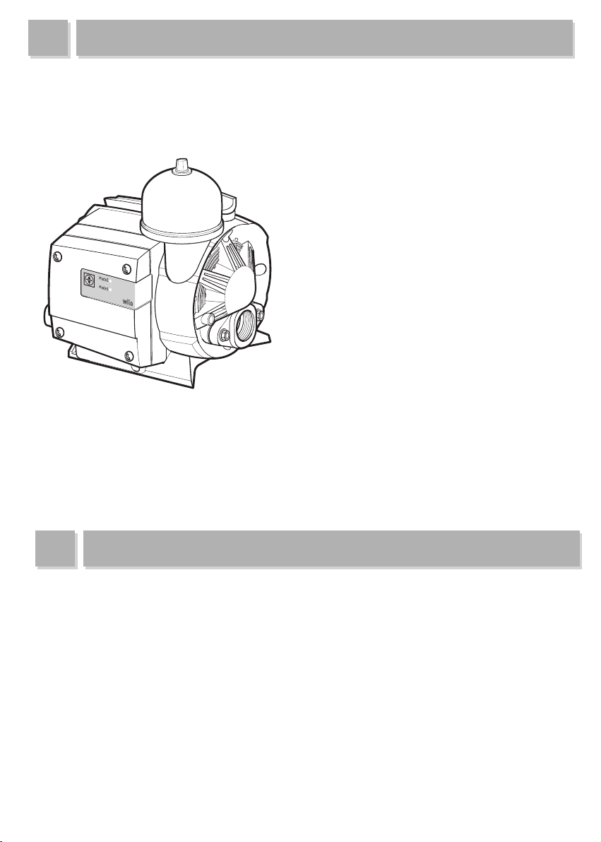
THANK YOU FOR PURCHASING THIS PUMP.
AUTOMATIC PRESSURE BOOSTING PUMP
▶This manual includes installation and operation instructions for PE model of WILO Pumps.
▶To keep the pump at top efficiency, follow the recommended instructions in this manual.
▶In case of lending the pump, this manual should be attached.
▶Improper operation not outlined in this manual may cause defects or physical damage that users are liable for.
▶Keep this manual handy for future reference.
FEATURES OF THE PUMP
▶ Energy-saving : Up to 15% Compared to current models with inverter technology.
▶ Automatic control : Advanced auto-control by pressure sensor .
▶ Anti-rust : New material and coating technology application.
▶ Low noise : Silent operation 50db or less.
▶ Protective function : Protection from frost, dry running.
▶ LED panel : Operation mode & abnormal operation alarm display.
2
Page 3

CONTENTS
Thank you for purchasing our pump.
Follow the recommended instructions in this manual.
Thank you for
purchasing our pump
Features
Contents
Safety instructions
Transportation and
Installation instructions
Operating instructions
Dimension and parts
Setting the operating mode
Protective functions & Alarms
Specifications
Wiring diagram
Performance curve
Troubles and counter-measures
...........................................................................................
..........................................................................................
............................................................................
...............................................................
...................................................................
...................................................
...........................................................
.............................................................
.............................................
........................................
.........................................................................
..................................................................
...................................
2
2
3
4
~
58
9
10
10
11
11
12
13
14
3
Page 4

SAFETY INSTRUCTIONS
These instructions contain important information which must be followed when installing and operating the
pump. These operating instructions must therefore be read before assembly and commissioning by the installer
and the responsible operator. Both the general safety instructions in the "Safety precautions" section and those
in subsequent sections indicated with danger symbols should be carefully observed.
●
Indication of instructions in the Operating instructions
Safety precautions in these operating instructions which if not followed could cause personal injury are
indicated by the symbol: electrical warnings are indicated with:
The following symbol is used to indicate that by ignoring the relevant safety instructions, damage could be
caused to the pump/machinery and its functions:
ATTENTION!
●
Staff training
The personnel installing the pump must have the appropriate qualifications.
●
Risks incurred by failure to comply with the safety precautions
Failure to comply with the safety precautions could result in personal injury, damage to the pump, or damage
to the installation. Failure to comply with the safety precautions could also invalidate any claim for damages.
In particular, lack of care may lead to problems such as:
-
Failure of important pump or machinery functions,
-P
ersonal injury due to electrical, mechanical and bacteriological causes.
●
Safety precautions for the operator
Existing regulations for accide nt pr eventio n mus t be followed. Dangers ca used by el ectrica l energy
are to be excluded. Directives issued by the VDE German Association of Electrical Engineers and the local
electricity supply companies are to be observed.
●
Safety information for inspection and assembly
The operator must ensure that all inspection and installation work is carried out by authorized and qualified
specialists who have carefully studied these instructions. Work on the pump/machinery should only be
carried out when the machine has been brought to a standstill.
●
Unauthorized modification and manufacture of spare parts
Alterations to the pump or installation may only be carried out with the manufacturer's consent. The use of
original spare parts and accessories authorized by the manufacturer will ensure safety. The use of any other
parts may invalidate claims invoking the liabilitty of the manufacturer for any consequences.
●
Unauthorized operating methods
The operating safety of the pump or installation supplied can only be guaranteed if it is used in accordance
with paragraph 1 of the operating instructions. The limiting values given in the catalogue or data sheet must
neither be exceeded nor allowed to fall below those specified.
4
Page 5
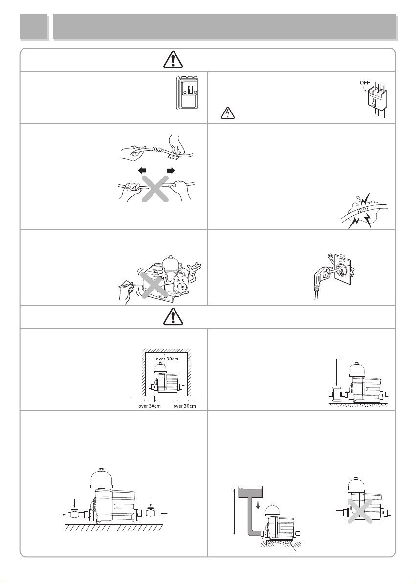
TRANSPORTATION AND INSTALLATION
●
Install a breaker of electric leakage
of under 30mA of rated sensitivity
to prevent electric shock.
●
The power cord must not be
bent, tied, pulled
or twisted by force.
Electric leakage,
electric shock, or fire
can occur.
●
Don’t clasp the power cord in transportation
and installation. The damaged cord may cause
electric leakage or shock.
WARNING!
Breaker
●
Before installation, repair or removal
of the pump, the power supply must be
disconnected.
Breaker
●
Pay special attention to extensions of the power cord.
Any electric leakage or disconnection in the extension
may cause electric shock.
●
How to extend the power cord.
①
Peel off the rubber/plastic insulation of the cable
as long as the connection terminal is.
②
Insulate the connection and cover it with rubber tape.
Then tightly cover it over four times
with friction tape.
●
Use a rated outlet with
voltage fluctuation
of less than
●
To prevent electric shock,
never plug in a power
cord under wet
±
10%.
AC220/230V
power cord
or plug
conditions.
●
Install the pump where the pump can be
conveniently checked or
repaired after installation.
If the space for the pump
is narrow, make the room
as described on the figure.
●Install a stop valve on the suction side and the
discharge side of the pump
for easier pump
maintenance.
Stop valveStop valve
CAUTION!
●
When the pump is highly likely to suck in dust or
foreign material, install a sand filter.
Failure to do so may cause a decline
in pressure and quantity
of pumped water, and
malfunction of the inverter.
●
If the suction height exceeds 10m, it can lead to the
function of abnormal overpressure or damage to the
product. Use under 1kgf/cm
(Example: The maximum height from the suction
must be under 10m)
●
Do not connect to town water directly. It can lead to
malfunction or damage to the product.
Hmax.
10m
ground
a concrete floor
5
2
over 4kgf/cm
water pressure
Sand filter
2
Page 6

drinking
water
TRANSPORTAION AND INSTALLATION
CAUTION!
●
When the power cord is extended, a voltage drop that keeps the pump from
operation may be caused. Refer to the table for extended power cord.
Length of power cable
shorter than 50 m
shorter than 200 m
●
Minimize the number of elbows to prevent water leakages in the piping and
nominal dimension of the cable
larger than 1.5mm
arger than 2.0mm
l
2
2
to decrease water resistance.
●When installing the pump,
make waterways to prevent
●Handle the pump with care.
Do not drop.
damage caused by water
leakage.
Pay special attention to a
basement, kitchen, and attic.
waterway
●When the pump is used for
drinking water,
Damage may occur.
●Set an alarm system to notify
the malfunction of the pump.
a water purifier must be
installed
※The pump has no
purification ability.
●The permitted voltage fluctuation is within 10% of
the rated voltage. Otherwise contact a power
company.
●The pump should not be connected directly to
public waterworks. Permission from the authority
should be granted. This could shorten the life of
the pump.
●Don’t expose the pump
to direct sunrays or to rain,
otherwise faulty parts or an
electric shock may be
caused.
6
Page 7

INSTALLATION
Wiring
Only a qualified electrician should connect cables. Install a circuit breaker and connect
ATTENTION!
earth wire to prevent any electrical accidents including electric shock.
- The wiring of major parts including the motor and the pressure sensor is already finished. Wiring of earth
and other optional parts should be conducted according to the wiring diagram.
- The power supply should be in accordance with the rated value marked on the nameplate.
- Before supplying power, check the following:
①if the circuit breaker at power is suitable (under 30mA of rated sensitivity).
②if the wiring is correct (connection and wire size).
③If the connections with motor terminal are tightened (No operation with missing phase).
CAUTION!
In winter, install protections against cold weather.
●When the pump remains inactive for a long time at temperatures lower than 0°C, the pump body must
be completely empty through the drain valve to prevent possible cracking of the hydraulic components.
●Bury the horizontal piping at least 30cm under ground.
CAUTION! To prevent a fire, don’t cover the motor or pump with a blanket.
Cover the exposed piping.
lagging
wooden plate
ground
waterway
summer / not humid
over 30cm
waterway waterway
winter
WARNING!
●At first running, if you notice abnormal vibration, noise, or strange smell, turn off and disconnect the pump
from its source and contact the dealer or service center. Continuous operating in this case may cause fire or
electric shock.
●Don’t ever disassemble or alter the product.
-Fire, electric shock, or physical injury may occur.
-The pump must not be dismantled and repaired except by qualified skilled personnel.
- Contact our service center or dealer to have the pump repaired.
●When the power cord is broken, the replacement should be carried out by our dealer or other qualified personnel.
CAUTION!
●After assembled, the pump should be put to test running.
Incorrect assembly may cause malfunction, electric leakage, or water leakage.
7
Page 8

INSTALLATION
4
8
7
1
1
9
6
6
2
5
-. Close the discharge valve(2) and open the Pressure Tank(4).
-. Open the suction valve(1) to fill the pump with water.
If don’t fill water in pump, please open the air vent screw(3).
-. Close the air hopper cap(3) and the Pressure Tank(4)
when water comes out from the air vet screw.
-. Open the discharge valve(2) after turning on the pump.
Part Description
1. Stop valve on the
uction side
3
s
2. Stop valve on the
discharge side
. Hopper cap
3
4. Pressure Tank
. Drain screw
5
6. Pipe support
7. Strainer
8. Water tank
9. Piping
8
Page 9

OPERATING INSTRUCTIONS
WARNING!
●To prevent a fire, never wrap the motor of the pump head in a blanket or a cloth to
prevent freezing in cold weather.
The customers are liable for any damage caused by improper wrapping.
CAUTION!
●Never conduct a shut-off operating under dry running condition
and delivering no water.
The life of the parts may be shortened
and explosion may occur.
●In electricity failure, disconnect the pump with the
power supply. Sudden start up may cause physical
damage.
electricity
failure
●Disconnect the pump if it is unused
for a long time.
Otherwise old insulation
may cause electric
shock or fire.
●Never use hot water over 35
℃
in the pump. Rubber
parts and packing may be deformed,
and motor may
be damaged.
●If water penetrates into the motor,
malfunction or electric leakage
may occur.
●Never use the pump with liquids other than water.
A fire may be caused,when chemicals or flammable
liquids including petroleum, alcohol, or gasoline are
used. In addition, the service
life of the pump may be
shortened and
malfunctions are
highly likely to occur.
●
Never alter an automatic item into non-automatic
one. Reconstruction of the pump is prohibited.
● Any physical damage and property losses
Alcohol
Gasoline
Oil
cannot be compensated in this case.
9
Page 10

DIMENSION AND PARTS
1
95
1
51
2
07
162
232
50
258
Pressure tank
Hopper cap
Terminal cover
Display LED
Power cord
Discharge
Drain screw
Casing
Flange
Suction
SETTING THE OPERATING MODE
Control button
Operating mode
Display indicator Mode
Green LED Auto Mode 1
Red LED Auto Mode 2
Green/Red LED(+ Suction Pressure) Auto Mode 3 -
Green/Red LED flashing simultaneously Manual Mode1 Constant high speed driving
Green/Red LED flashing by turns Manual Mode2 Constant medium speed driving
Pressure
Range
Red LED
Green LED
Condition
PE-410MA PE-350EA
1.0~2.3kgf/㎠ 1.0~1.6kgf/㎠
1.5~2.3kgf/㎠ 1.5~1.6kgf/㎠
1.5~1.6kgf/㎠
PE-410MA PE-350EA
How to control the button
(when push the button, below 1-2-3-4 repeating)
1. Push the button one time : Auto mode 1 →Auto mode 2
2. Push the button two times : Auto mode 2
3. Push the button Three times : Manual mode 1
4. Push the button four times : Manual mode 2
→Manual mode 1
→Manual mode 2
→Auto mode1
How to control the button
(when push the button, below 1-2-3-4-5 repeating)
1. Push the button one time : Auto mode 1 →Auto mode 2
2. Push the button two times : Auto mode 2
3. Push the button three times : Auto mode 3
4. Push the button four times : Manual mode 1
5. Push the button five times : Manual mode 2
10
→Auto mode 3
→Manual mode 1
→Manual mode 2
→Auto mode1
Page 11

PROTECTIVE FUNCTIONS & ALARMS
①Frozen protection : Green LED flashes
When water inside the pump reaches freezing temperatures, it makes pump operated automatically and
prevent damage from frost by a temperature sensor.
②Dry running protection : Red LED flashes
The pump automatically stops after 10seconds when driving with no water inside the pump.
Automatically return to operation after 10 minutes.(Continuous dry running_10 seconds/10 minutes repeat
when dry running continues)
③Operation disconnection and overload protection : Red LED flashes
The pumps stops when the temperature inside the pump exceeds a certain level,
automatically return to operation when the temperature inside the pump reaches a certain level below.
④Leakage operation protection : Red LED flashes
The pumps stops when the temperature inside the pump exceeds a certain level,
automatically return to operation when the temperature inside the pump reaches a certain level below.
⑤Over-pressure protection : Red LED 3time sand Green LED 3 times flashes alternately
The pumps stops when the inside pump pressure exceeds 5kgf/㎠,
automatically return to operation when the inside pump pressure becomes less than 5kgf/㎠
SPECIFICATIONS
Power
Input
Output
Hmax.
Qmax.
Pipe
Insulation Class
Weight
PE-410MA
1P,220V,60Hz
490W
350W
25m
60 l/min
11
PE-350EASpecification
1P, 220-230V, 50Hz
380W
300W
18m
55ℓ/min
25mm (1”)
IPX4
5.5kg
Page 12

WIRING DIAGRAM
50Hz
PE-410MA
PE-350EA
PERFORMANCE CURVE
PE-410MA
PE-350EA
12
Page 13

TROUBLES AND COUNTER-MEASURES
Troubles Causes
Motor does
not start.
Water is not
pumped out
although
motor runs.
Thermal protector
for motor works
too often.
Thermal protector.
Faulty cord connection.
Cord disconnected.
Trouble in motor.
Too low power supply voltage.
Water level of well is lower
than standard level.
Trouble in check valve.
Air drawn into suction pipe. After checking the joints of piping, shut
Air drawn into pump from
mechanical seal.
Too low or high power supply
voltage.
Impeller is contact with
another part.
Counter-Measures
(The indication ●can be done by user.)
● If the motor is overheated, it doesn’t
operate.Then, wait till getting cold.
(20~30 minutes)
● Insert the plug securely.
Replace the new cord.
Repair or replace the motor.
Consult with the power supply company.
●
●
Check the water level of well.
Take off the check valve case. Then, clean the
valve, the valve seat and the valve hole.
them perfectly.
Replace the new mechanical seal.
●
Consult with power supply company.
Repair the defects.
Water does not
come out at the
first few minutes
after switch on.
Pump starts
though no water
is being used.
Short or open circuit of the
capacitor.
Air drawn into suction pipe.
Water leaks at piping or pump.
Water leaks at mechanical seal.
Trouble in check valve.
Defacement or transformation
of the impeller.
13
Repair the capacitor.
Replace the defects of piping
(To prevent air leaking)
Repair piping, pump parts and faucets etc.
Repair the mechanical seal.
Take off the check valve case.
Then, clean the valve the valve seat
and the valve hole.
Replace the impeller.
Page 14

MEMO
14
Page 15

MEMO
15
Page 16

P/NO. : 3057974 ( Rev.2 )
Apr.2015 Printed in Korea.
?
The leaflet must be given to the end user and be left on site.
 Loading...