

Page 1
Wilo-Economy MHIE 1~
Pioneering for You
4 090 996-Ed.04 / 2016-04-Wilo
de Einbau- und Betriebsanleitung
en Installation and operating instructions
fr Notice de montage et de mise en service
nl Inbouw- en bedieningsvoorschriften
es Instrucciones de instalación y funcionamiento
it Istruzioni di montaggio, uso e manutenzione
pt Manual de Instalação e funcionamento
ru Инструкцияпомонтажуиэксплуатации
Page 2
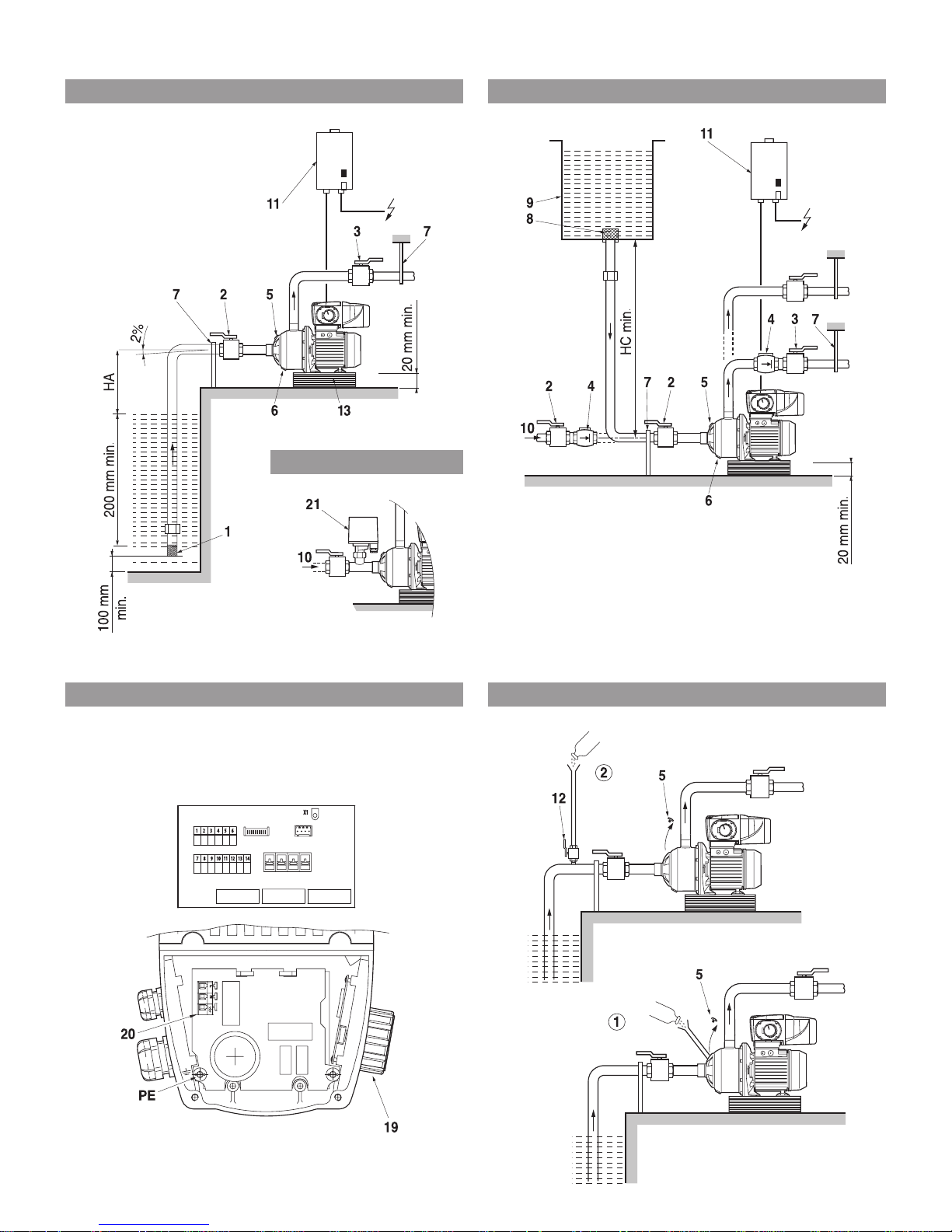
Fig. 1:
Fig. 3:
Fig. 2:
Fig. 4:
Fig. 5:
or/ou
or/ou
Page 3
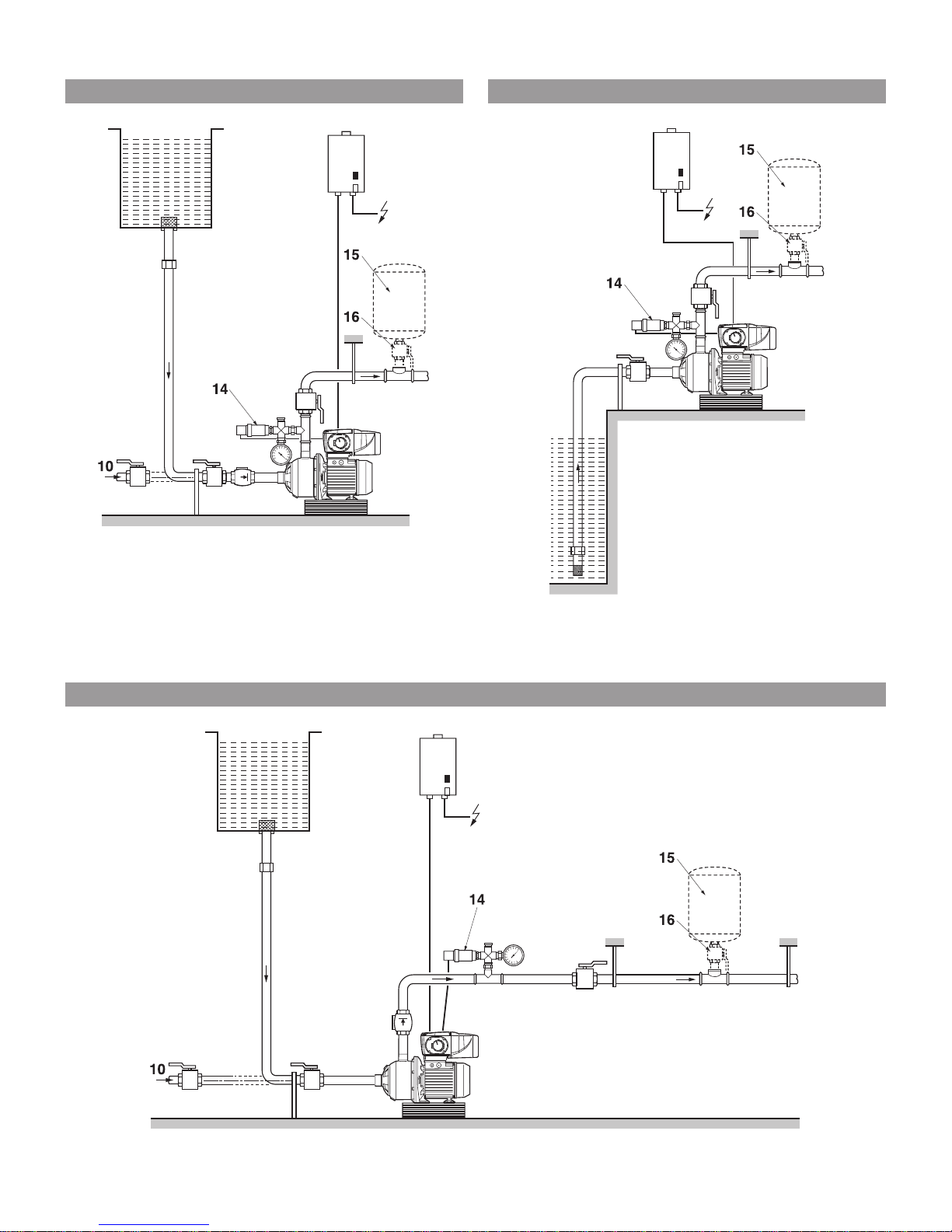
Fig. 6: Fig. 7:
Fig. 8:
or/ou
or/ou
Page 4
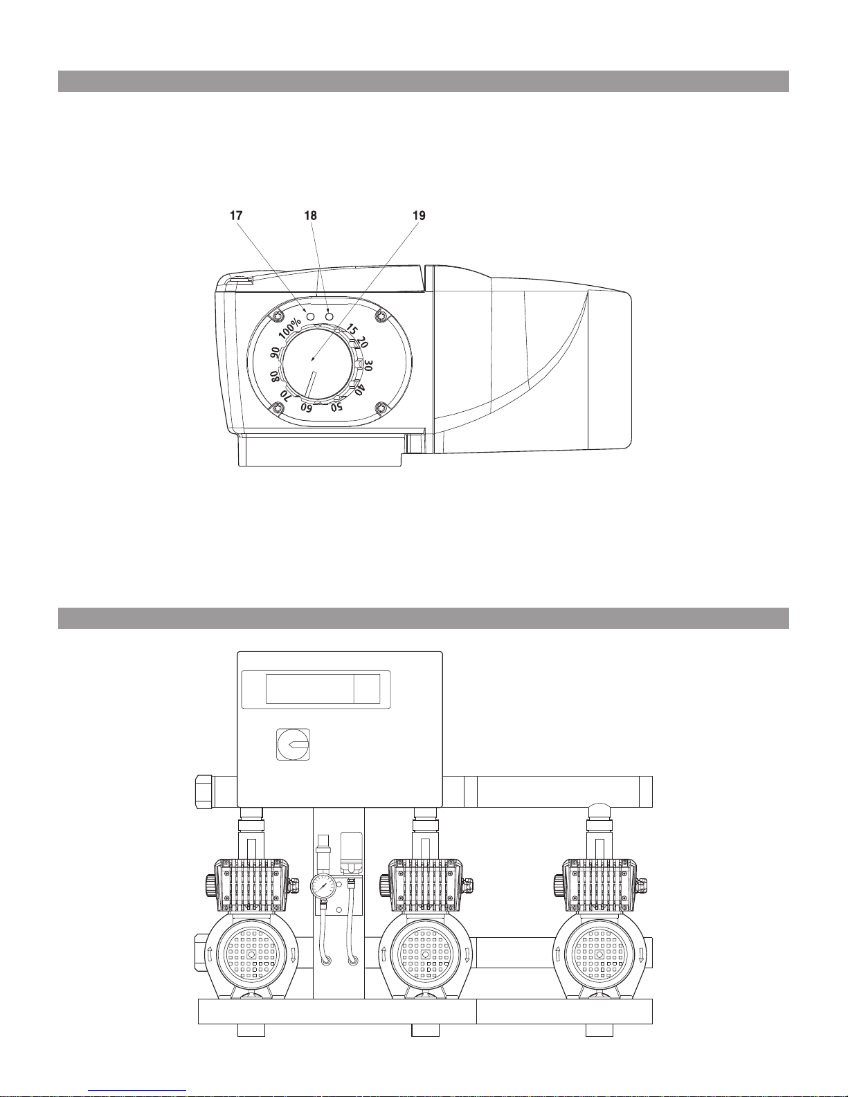
Fig. 9:
Fig. 10:
Page 5
English
19
1 General
1.1 Applications
Pumps for pumping clear liquids in the residential
sector, in agriculture and in industry. Intake from
wells, springs, water streams, ponds ... not to be
used with Abyssinian wells (driven wells).
1.2 Technical data
• Maximum operating pressure: 10 bar
• Minimum intake pressure: 6 bar
• Temperature range:
- Version with seals and inserts made of EPDM*:
-15° to +110°C
- Version with seals and inserts made of VITON*:
-15° to +90°C
• Suction head:
depending on the Net Positive Suction Head
(NPSH) of the pump
• Ambient temperature (standard):
+40°C (in cases of higher temperatures, please
consult Wilo after-sales service)
• Sound pressure level 50/60Hz 0/+3 dB(A): 66
*Application in potable water sector: WRAS: English standard,
KTW: German standard.
2 Safety
These Installation and operating instructions contain basic information which must be adhered to
during installation and commissioning. For this
reason, these Installation and operating instructions must, without fail, be read by the service
technician and the responsible operator before
installation and commissioning. It is not only the
general safety instructions which are listed here
under the main heading of Safety which must be
complied with, but rather also the special safety
instructions which are listed under the following
main headings.
2.1 Identification of notes in the Installation and
operating instructions
The safety instructions contained in these
Installation and operating instructions which, if
they are not observed, could endanger personnel, are specially marked with the General danger
symbol,
and with
in cases of warnings against electrical voltage.
The word
is included with safety instructions which, if they
are not observed, could endanger the installation
and its function.
2.2 Personnel qualifications
The personnel responsible for installation must
be in possession of the respective qualifications
required for this work.
2.3 Danger in the event of nonobservance of the
safety instructions
The failure to observe the safety instructions
could result in dangers to personnel and pump/
installation. Nonobservance of the safety instructions can result in the loss of any claims to damages.
In particular, the failure to observe these instructions could lead to the following hazards:
• Failure of important functions of the pump/installation.
• Hazards to personnel resulting from electrical,
mechanical or bacteriological actions,
• Property damage.
2.4 Safety instructions for the operator
The existing regulations regarding accident prevention are to be complied with.
Hazards connected with electrical energy are to
be excluded. The regulations of the VDE (Verband
der Elektrotechnik Elektronik und Informationstechnik e.V.) and of the local energy supply companies are to be complied with.
2.5 Safety instructions for inspection and installation work
It is the responsibility of the operator to ensure
that all inspection and installation work is carried
out by authorised and qualified professionals
who have acquired sufficient information from a
detailed study of the Installation and operating
instructions.
As a fundamental principle, work may only be carried out on the pump/installation when it/they are
at a standstill.
2.6 Customer’s own conversions and spare parts
manufacture
Modifications to the pump/installation are not
permitted except after consultation with the
manufacturer. The use of original spare parts and
manufacturer-authorised accessories promotes
safety. The use of other parts could lead to the
cancellation of liability for the results of such
substitutions.
2.7 Improper use
The operating safety of the supplied pump/installation is only guaranteed for conventional use
in accordance with Section 1 of the Installation
and operating instructions. It is not permitted to
exceed or fail to meet the limit values specified
in the catalogue/data sheet under any circumstances.
3 Transport, handling and storage
The pump/installation is to be checked at once
upon delivery for any damage that may have
occurred in transit. If any damages are found, then
they are to be reported to the transport company
immediately within the time periods specified.
If the material is to be installed later,
then it must be stored in a dry location.
The material must be protected against
impact shocks and all external influences (moisture, frost, etc.).
Handle the pump carefully so that the geometry
and alignment of the installation are not altered.
The pump is not permitted under any
circumstances to be raised on the frequency converter.
ATTENTION!
ATTENTION!
ATTENTION!
WILO SE 04/2016
Page 6

English
20
4 Products and accessories
4.1 Description (see Fig. 1-9):
1 : Foot valve with suction strainer (maximum
free-flowing cross-section 1 mm)
2 : Stop valve; on suction side
3 : Stop valve; on the pressure side
4 : Non-return valve
5 : Inlet/bleeder screw
6 : Drainage screw
7 : Pipe bracket
8 : Suction strainer
9 : Replenishment reservoir
10 : Tap water network
11 : Switch, switch amplifier with fuses
12 : Cock
13 : Pedestal
14 : Pressure sensor
15 : Diaphragm pressure vessel
16 : Gate valve for diaphragm pressure vessel
17 : Red LED
18 : Green LED
19 : Potentiometer
20 : Connection terminal
21 : Protection against low water level
HA : Maximum suction head
HC : Minimum suction head
4.2 The pump
Horizontal centrifugal pump.
Multistage, not self-priming.
Suction/outlet openings with thread.
Axial suction, radial outlet upwards.
Sealing on shaft passage by means of standard
mechanical seal.
4.3 The motor with frequency converter
Three-phase AC motor, two-pole, with frequency
converter.
Protection class: IP 54.
Insulation class: F
4.4 Accessories (optional)
• Suction kit
• Shut-off device
• Diaphragm pressure vessel
• Tank
• Non-return valve
• Foot valve with suction strainer
• Compensator
• Protection against low water level
(potable water network)
(see Fig. 5, Pos. 21)
• Pressure sensor control kit (sensor precision:
# 1%; utilisation between 30% and 100% of the
reading range).
5 Installation
Two types:
• see Fig 1: Suction mode.
• see Fig. 2: Pressure operation from replenish-
ment vessel (Pos. 9) or potable water network
(Pos. 10).
5.1 Installation
Install the pump at a readily accessible location
which is protected against external influences
(excessive rain or sunlight, frost) and which is as
near as possible to the extraction point.
Place the pump on a pedestal (Pos. 13) or directly
on a smooth, level base. Fixation of the pump
with 2 holes for Ø M8 bolts.
Note that the height of the installation
location and the temperature of the
fluid will diminish the suction capacity
of the pump.
Installation should be carried out in
pressure operation when temperatures
exceed 80°C.
5.2 Pipe connections
The installation must be sufficient for
the pressure that the pump generates
at maximum frequency and zero flow
volume.
- Connection with spiral-reinforced flexible hoses
or rigid pipe.
- Seal the pipe connections well with suitable
products. No air is permitted to enter the suction line; lay the suction line with a continuous
rise (2%) (see Fig. 1).
- In the case of rigid pipes, take care to ensure that
the weight of the lines is not borne by the pump
alone. Utilise supports and/or pipe brackets (see
Figs. 1 + 2, Pos. 7).
Pump MHIE
type 200 400 800
Suction 1"1/4 - 1"1/2 -
opening 1"- (26-34) (33-42) (40-49)
Outlet 1" - 1"1/4 -
opening 1" - (26-34) (26-34) (33-42)
Pipe connections
Height Height loss Temperature Height loss
meter
0.00m 0.00mCL 20°C 0.20mCL
500m 0.60mCL 30°C 0.40mCL
1000m 1.15mCL 40°C 0.70mCL
50°C 1.20mCL
60°C 1.90mCL
70°C 3.10mCL
80°C 4.70mCL
90°C 7.10mCL
100°C 10.30 mCL
110°C 14.70 mCL
120°C 20.50 mCL
ATTENTION!
ATTENTION!
ATTENTION!
Frequency 50 Hz 60 Hz
Voltages 1~230 V (±10%) 1~220 V (±6%)
Operational voltages and frequencies
WILO SE 04/2016
Page 7

- The diameter of the suction line is never permitted to be smaller than the suction/pumping opening of the pump.
- Limit the horizontal length of the suction line
and avoid all possible sources of pressure losses
(elbows, valves, neckings, etc.).
Possible damage to the pump!
In order to protect the pump against
fluid hammers, install the non-return
valve on the pressure side.
In the frequency converter, the testing current
circuits are shielded from the performance
circuits with the aid of a simple insulation
(CEI664-1).
The installer must ensure that the external
testing current circuits (e.g.: pressure sensors,
external control of the setpoint…) are shielded
against any possible contact with people. If the
testing current circuits are to be connected to
the electric circuits corresponding to the safety specifications of the SELV (TBTS), then an
additional insulation must be installed in order
to comply with the SELV (TBTS) classification.
5.3 Electrical connections
The electrical connections and testing must
be carried out by a licensed electrician and in
accordance with locally applicable standard
specifications.
The electrical properties (frequency, voltage,
nominal current) of the motor frequency converter are indicated on the name plate of the motor/
of the pump. A check is to be made as to whether
the motor frequency converter matches the current supply network to which it is intended to be
attached.
The frequency converter is equipped with a motor
protection feature. Constant protection of the
motor and of the pump are ensured by a continuous nominal/actual comparison of the current and
stored data.
In the event of excessively great resistance on
the part of the neutral conductor, a corresponding protection device must be installed upstream
from the motor frequency converter.
As a basic rule, provide switch amplifiers with
fuses (Type GF) for the protection of the network
(see Figs. 1 + 2, Pos. 11).
If a residual-current-operated protection switch
needs to be installed for personnel protection,
then use a selective universal-current-sensitive
residual-current-operated protection switch
with VDE certificate!
Adjust the safety switch in accordance with the
data specified on the name plate of the frequency converter.
Use connecting cables that meet applicable standards.
Earth the pump/installation in accordance with
regulations.
English
21
ATTENTION!
WILO SE 04/2016
Page 8

The electrical connection of the frequency converter must correspond to the diagrams contained
in the following table:
The frequency converter could be damaged if connected incorrectly.
The electric cable is never to be allowed to
come into contact with either the pipe or the
pump. Furthermore, it must be completely
shielded against moisture.
Property damage is possible!
Because of operational settings, an
incorrectly disconnected core in the connection area could damage the frequency
converter.
• Disconnect the core at both of its end
points from electrical connection
• Pull it off
English
22
Details concerning the electrical connections - loosen screws and remove upper cover of the frequency converter.
Mains connection
Connect three lines of the cable to the 3
connection terminals of the board.
(Phase + Neutral+ Earth).
Connecting the inputs/outputs
3 operating modes exist:
(see Chapter 6: Commissioning)
manual mode: Mode 1
Pressure regulation: Mode 2
Operation by external control: Mode 3
NOTE: The configuration at the time of
delivery is either Mode 1-3 or Mode 2,
depending on the desired type of pump
control unit. A programming key is used
to switch from Mode 1-3 to Mode 2 (or
vice-versa); an after-sales service employee
must be called in.
Cores
Ø 2.5 mm
2
Connection terminal
Main fuse 20 A
Connection terminals
inputs/outputs
(see
Fig. 3,
Pos. 20)
(see
Fig. 3)
+24 V DC max. 30 mA
+10 V DC max. 30 mA
Zero Volt
External ON/OFF
Error relays
potential-free contact: 250 V–1 A
1 2 3 4 5 6 7 8 9 10 11 12 13 14
L N
ATTENTION!
PE
+24 V
+24 V
0 V
+10 V
ATTENTION!
WILO SE 04/2016
Page 9

English
23
1 - Connection of the pressure sensor
Connection of the inputs/outputs Connection terminals Inputs/outputs of the frequency converter
Diagram
Pressure sensor 4-20 mA (*)
•
2 cores (4-20 mA / +24 V)
•
3 cores (0 V / 4-20 mA / +24 V)
or
Pressure sensor 0-10 V (**)
•
3 cores (0 V / 0-10 V / +24 V)
1
1
10 V
0 V
+24 V
+24 V
2345678910 11 12 13 14
0 V 4-20 mA +24 V
*
0 V 0-10 V+24 V
**
2 - Connection of the potentiometer
Connection terminals Inputs/outputs of the frequency converter
Diagram
Adjusting the setpoint with the
aid of the potentiometer
Adjusting the setpoint via external control
•
0-20 mA (*)
or
•
0-10 V (**)
2
1
10 V
0 V
+24 V
+24 V
2345678910 11 12 13 14
1234567
3
1
10 V
0 V
+24 V
+24 V
23456 78910 11 12 13 14
0-20 mA 0 V
*
0-10 V0 V
**
1234567
WILO SE 04/2016
Page 10

English
24
3 - Settings of the control terminals (Terminals 7 to 14)
Connection terminals of the inputs/outputs of the frequency converter
Diagram
4
1
10 V
0 V
+24 V
+24 V
2345678910 11 12 13 14
5
1
10 V
0 V
+24 V
+24 V
2345678910 11 12 13 14
6
1
10 V
0 V
+24 V
+24 V
2345678910 11 12 13 14
7
1
10 V
0 V
+24 V
+24 V
2345678910 11 12 13 14
4 - Possible connections
It is possible to start or stop the pump with the
external control(*) (potential-free contact);
this function takes precedence over the other
functions.
This external control can be removed by bridging
the terminals (11 and 12).
Examples: Float switches,
low water pressure switches, etc.
The frequency converter is equipped with an
error relay with normally open contact (**):
Contact open = frequency converter is receiving
no voltage or is defective
1
10 V
0 V
+24 V
+24 V
2345678910 11 12 13 14
*
1
10 V
0 V
+24 V
+24 V
2345678910 11 12 13 14
**
WILO SE 04/2016
Page 11

Property damage is possible!
The cover of the frequency converter
must be easy to close.
• Put plug connections carefully in place
in the interior of the frequency converter before sealing it.
English
25
Operating modes and diagrams
Diagrams
+
+
+
+ +
+ +
+ +
+ +
+ +
+ +
2 4
3 6
3
21 4
21 5
31 6
31 4
31 7
31 5
4
ATTENTION!
Operating modes
Mode 1
Mode 3 – 0-20 mA
Mode 3 – 0-10 V
Mode 2 – PI control – sensor: 4-20 mA
Mode 2 – PI control – sensor: 0-10 V
Mode 2 – PI control – sensor: 4-20 mA – External control of the setpoint: 0-20 mA
Mode 2 – PI control – sensor: 4-20 mA – External control of the setpoint: 0-10 V
Mode 2 – PI control – sensor: 0-10 V – External control of the setpoint: 0-20 mA
Mode 2 – PI control – sensor: 0-10 V – External control of the setpoint: 0-10 V
WILO SE 04/2016
Page 12

English
26
Control regulations in Mode 2
External control of the setpoint in Mode 2
External control of the frequency in Mode 3
Value in % of the maxi-
mum pressure measure-
ment range of the sensor
100%
0 4 20
Sensor 4-20 mA
Between 0 and 4 mA it is assumed that the
cable is disconnected.
Input current level (mA)
Value in % of the maximum
pressure measurement range
of the sensor
100%
0 10
Sensor 0-10 V
Input voltage (V)
Pressure in % of the
sensor measurement
range
100%
0 2 20
Setpoint 0-20 mA
Range in which the frequency converter stops.
Input current level (mA)
Pressure in % of the
sensor measurement
range
100%
0 1 10
Setpoint 0-10 V
Range in which the frequency converter stops.
Input voltage (V)
Frequency of the
frequency
converter
100%
40%
0 2 20
External signal 0-20 mA
Range in which the frequency converter stops.
Input current level (mA)
Frequency of the
frequency
converter
100%
40%
0 1 10
External signal 0-10 V
Range in which the frequency converter stops.
Input voltage (V)
10% 10%
WILO SE 04/2016
Page 13

English
27
6 Commissioning
If the pump is supplied separately, i.e. if
it is not integrated in a system that has
been mounted by us, then the configuration type at the time of delivery is
either Mode 1-3 or Mode 2, depending
on the type of pump control desired.
As a reminder: A programming key is
used to switch from Mode 1-3 to Mode
2 (or vice-versa); an after-sales service
employee must be called in.
6.1 Settings
- In manual mode: Mode 1 (see Figs. 1, 2).
The duty point of the pump is reached with the
aid of the potentiometer (see Fig. 9, Pos. 19) by
setting the speed of the motor between 40% and
100% of the maximum speed.
We recommend that the motor speed be set to
70 % for commissioning.
- The pump can be brought to a standstill (frequency converter under tension) with the remote
control unit (switch).
- In pressure regulation operating mode: Mode 2
(see Figs. 6, 7, 8).
It is possible to regulate the pressure of the
pump through the addition of a pressure sensor
and a diaphragm pressure vessel. The sensor
must exhibit an accuracy of <1% and be used in
a range between 30% and 100% of its measurement range; the reservoir has a useable volume
of at least 8 litres.
No water in the diaphragm pressure vessel.
Pump up the diaphragm pressure vessel to a
pressure that is 0.3 bar less than the control
pressure of the pump (diaphragm pressure ves-
sel and sensor kit included as accessories in the
scope of delivery).
The setpoint for the pressure regulation is specified in two types:
• The setting of the potentiometer indicates for
the setpoint for a value between 0 and 100% of
the measurement range of the sensor. We recommend that the potentiometer be set to
100% for commissioning.
• An external signal can be connected (0-10 V
or 0-20 mA) for setting the setpoint by remote
control (see Chapter 5.3 - Electrical connec-
tions).
NOTE: The function «Detection of zero volume
flow» makes it possible to stop the pump.
- Via external control per frequency: Mode 3 (see
Fig. 10).
The potentiometer has no function in Mode 3, but
it must nonetheless be set to 100%. The pump is
controlled by an external signal.
Specifications concerning commissioning: see
instruction manual for the pressure boosting system.
During normal operation, the status of the LEDs
is as follows: (see Fig. 9, Pos. 17 + 18)
6.2 Preparatory flushing
Because our pumps are hydraulically tested in
the factory, it is possible that there is still water
in their interiors. For reasons of hygiene, it is
therefore recommended that they be flushed
out prior to use in a potable water network.
6.3 Filling - bleeding
Never permit the pump to run dry, not
even for a brief moment.
Pump in intake mode (see Fig. 2)
-
Close the stop valve on the pressure side (Pos. 3),
open the inlet/bleeder screw (Pos. 5).
- Gradually open the valve that is located on the
pipework at the entry to the pump (Pos. 2)
and carry out the complete filling of the pump.
Retighten the screw firmly after water begins to
emerge and ventilation is complete.
Danger of injury to personnel!
A jet of water can escape from the ventilation
opening when hot water is being pumped.
Initiate all necessary precautionary measures to
ensure that personnel and the motor/frequency
converter are protected!
Pump in suction mode (see Fig. 1) Two different
cases are possible.
1st case (see Fig. 4.1)
- Close the stop valve on the pressure side
(see Fig. 1, Pos. 3).
- Open the stop valve on suction side (see Fig. 1,
Pos. 2).
- Unscrew the inlet/bleeder screw (see Fig. 1, Pos. 5),
that is located on the pump housing.
- Fill the pump and suction line completely with the
aid of a funnel inserted into the opening.
- The filling procedure is finished when water
escapes and ventilation is complete.
- Screw the inlet/bleeder screw back on.
2nd case (see Fig. 4.2)
The filling can be made easier if a pipe equipped
with a cock (Pos. 12) Ø 1/2» and a funnel
is mounted perpendicularly on the suction line
of the pump.
- Close the stop valve on the pressure side
(see Fig. 1, Pos. 3).
- Open the stop valve on suction side (see Fig. 1,
Pos. 2).
- Open cock (see Fig. 4, Pos. 12) and inlet/bleeder
screw (see Fig. 1, Pos. 5).
- Fill pump and suction line completely, until bubble-free water escapes from the filling opening.
- Close the cock (see Fig. 4, Pos. 12) (it can remain
mounted on the pipe), remove the pipe and screw
the inlet/bleeder screw back in.
Frequency converter voltage on off
load/pump in operation
Frequency converter voltage on off
load/pump in standstill
Status of the LEDs green LED red LED
ATTENTION!
ATTENTION!
WILO SE 04/2016
Page 14

English
28
6.4 Starting
Depending on the temperature of the fluid and
on the operating cycles of the pump, the surface temperature (pump, motor) may exceed
68°C: mount suitable personnel protection
apparatus as needed.
The pump should not be permitted to be
operated longer than ten minutes with
zero flow when the gate valve is closed
on the pressure side.
We recommend that a minimum flow level of
approximately 10% of the nominal throughput of
the pump be maintained in order to ensure that
no blow hole forms in the upper part of the pump.
- Open the stop valve on the pressure side and start
the pump.
- Check the uniformity of the pressure on the
discharge side with the aid of a pressure gauge;
bleed the pump again or refill it in the event of
deviations.
- Check current consumption. The current consumption may not exceed the specification on
the pump shield.
7 Maintenance
The pump(s) must be de-energised and
all non-authorised restarts must be prevented before any maintenance work is
done.
Never undertake maintenance work while the
pump is running. Always keep pump and motor/
frequency converter in clean condition.
When set up in frost-free locations, the pump
should not be emptied, even with prolonged
decommissioning.
To prevent blockage of the shaft and of the
hydraulic apparatus, the pump is to be emptied
during periods of potential frost by unscrewing
the drainage and inlet/bleeding screw (Fig. 1+2,
Pos. 5+6). Screw both screws back in without
tightening them.
Replacement frequencies
NOTE: These can only be regarded as recommen-
dations, because the frequency of replacement
is dependent on operating conditions within the
group involving
• Temperature, pressure and quality of the fluid for
the mechanical seal.
• Pressure and ambient temperature for the motor
and other components.
• Frequency of start-up: continuous or intermittent
operation.
ATTENTION!
ATTENTION!
WILO SE 04/2016
Page 15

English
29
8 Operating faults
De-energise the pump before each
intervention and secure against non-authorised restarts!
All of the incidents listed below will lead to
a switch-off via the error relay.
De-energise the pump before each intervention.
If the fluid is toxic, corrosive or hazardous for
personnel, then WILO or the authorised repair
company must be informed of the situation.
Clean the pump in such cases in order to ensure
absolute safety for the craftsmen performing
the repairs.
If the pump is at a complete standstill and an intervention is required, disconnect the power supply, wait until the LEDs have gone out completely, eliminate the fault
and reconnect the power supply. If a major fault is present, then an after-sales service employee must be called in.
If the operating fault cannot be rectified, then please
contact your local professional tradesmen or the Wilo
after-sales service in your vicinity.
ATTENTION!
Display Frequency converter beha-
viour
Fault/possible causes Elimination
Green
LED
Red
LED
Reaction time
up to standstill
Frequency
converter
Waiting time
before switching
back on
Relay status
Contact
Off On No standstill / Open a) Frequency converter sup-
ply has undervoltage.
- Check voltage at the
terminals of the frequency converter.
Off On Immediate No switching
back on
Open b) Frequency converter
supply has overvoltage.
- Check voltage at the
terminals of the frequency converter.
Off On Immediate No switching
back on
Open c) The motor has a short-cir-
cuit.
- Dismantle motor/
frequency converter
of the pump and have
it checked or replace it.
Off On <10 s No switching
back on
Open d) The pump is overloaded. - excessive density and/
or viscosity of the
pumped fluid.
Off On <60 s No switching
back on
Open e) The sensor cable
(4-20 mA) is disconnected
(only Mode 2).
- Check correct current
supply and cabling of
the sensor.
WILO SE 04/2016
Page 16

Other, pump-specific faults not detectable by
the frequency converter.
English
30
9 Spare parts
Spare parts must be ordered from the local authorised dealer and/or from Wilo after-sales service.
In order to avoid unnecessary inquiries or incorrect orders, specify at the time of your order all of
the data listed on the name plate.
Subject to technical changes without prior
notice!
Faults Causes Elimination
8.1 The pump is running but does not
pump anything
8.2 The pump is
vibrating
8.3 The pump does
not provide sufficient pressure
8.4 The delivery rate
is irregular
a) The pump is not running fast
enough:
b) Interior parts are blocked by foreign
matter:
c) Suction line is blocked:
d) Airintakethroughsuctionline:
e) The pump has run empty:
f) The suction pressure is too weak,
cavitation noise is occurring gene-
rally:
a) Poorly mounted to the pedestal:
b) Foreign matter is blocking the
pump:
c) Difficult pump rotation:
a) Insufficient motor speed:
b) The motor is defective:
c) Insufficient pump filling:
d) The drainage screw is not screwed
in all the way:
a) The suction head (Ha) has not been
maintained:
b) The suction line has a smaller circ-
umference than that of the pump:
c) Suction strainer and suction line are
partially blocked:
a) Check correct setting of the nominal values (setpoints)
(matching of the nominal value points).
b) Dismantle pump, replace defective parts, perform clea-
ning.
c) Clean the entire pipework.
d) Check the impermeability of the entire pipe up to the
pump and seal.
e) Refill the pump. Check the impermeability of the foot
valve.
f) Excessively large suction pressure losses or excessively
large suction head. (check the Net Positive Suction
Head of the installed pump and of the installation).
a) Check and tighten the nuts on the pedestal bolts.
b) Dismantle and clean the pump.
c) Check whether the pump rotates freely without
encountering abnormal resistance.
a) Check correct setting of the nominal values (setpoints)
(matching of the nominal value points).
b) Have the motor/frequency converter replaced.
c) Open the drain cock of the pump and bleed until there
is a complete absence of bubbles.
d) Check drainage screw and screw in as needed.
a) Consult the installation conditions and recommen-
dations contained in these Installation and operating
instructions.
b) The suction line must have the same diameter as the
suction inlet of the pump.
c) Dismount and clean.
WILO SE 04/2016
Page 17

Dortmund,
N°2117799.02 (CE-A-S n°4170921)
H. HERCHENHEIN
Person authorized to compile the technical file is :
Personne autorisée à constituer le dossier technique est :
Senior Vice President - Group ITQ
EN 809+A1
sowie auch den Bestimmungen zu folgenden harmonisierten europäischen Normen :
comply also with the following relevant harmonized European standards :
sont également conformes aux dispositions des normes européennes harmonisées suivantes :
EN 61800-3+A1:2012
EN 60034-1
EN 60204-1
et aux législations nationales les transposant,
EU/EG KONFORMITÄTSERKLÄRUNG
EU/EC DECLARATION OF CONFORMITY
DECLARATION DE CONFORMITE UE/CE
Als Hersteller erklären wir hiermit, dass die Pumpenbauarten der Baureihe
We, the manufacturer, declare that the pump types of the series
Nous, fabricant, déclarons que les types de pompes de la série
in der gelieferten Ausführung folgenden einschlägigen Bestimmungen entsprechen :
In their delivered state comply with the following relevant directives :
dans leur état de livraison sont conformes aux dispositions des directives suivantes :
und entsprechender nationaler Gesetzgebung,
_ Maschinenrichtlinie 2006/42/EG
WILO SE
44263 Dortmund - Germany
(Die Seriennummer ist auf dem Typenschild des Produktes nach Punkten b) & c) von §1.7.4.2
und §1.7.3 des Anhanges I der Maschinenrichtlinie angegeben. / The serial number is marked
on the product site plate according to points b) & c) of §1.7.4.2 and §1.7.3 of the annex I of
the Machinery directive. / Le numéro de série est inscrit sur la plaque signalétique du produit
en accord avec les points b) & c) du §1. 7.4.2 et du §1.7.3 de l’annexe I de la Directive
Machines.)
MHIE…/M…
Division Clean and Waste Water
Quality Manager - PBU Multistage
WILO SALMSON FRANCE SAS
80 Bd de l'Industrie - CS 90527
F-53005 Laval Cedex
and with the relevant national legislation,
Bevollmächtigter für die Zusammenstellung der technischen Unterlagen ist:
EN 61800-5-1
_ Elektromagnetische Verträglichkeit-Richtlinie 2014/30/EU ab 20 April 2016
_ Electromagnetic compatibility 2014/30/EU from April 20th 2016
_ Compabilité électromagnétique 2014/30/UE à partir du 20 avril 2016
_ Machinery 2006/42/EC
_ Machines 2006/42/CE
und gemäss Anhang 1, §1.5.1, werden die Schutzziele der Niederspannungsrichtlinie 2014/35/EU ab 20 A
pril 2016 eingehalten
and accor ding to the annex 1, §1.5.1, comply with the safet y objectives of the Low Voltage Directive
2014/35/EU from Apr il 20th 2016
et, suivant l'annexe 1, §1.5.1, respectent les objectifs de sécurité de la Directive Basse Tension 2014/35/EU à part ir du 20/04/2016
Page 18

(BG) - български език (CS) - Čeština
ДЕКЛАРАЦИЯ ЗА СЪОТЕТСТВИЕ EO ES PROHLÁŠENÍ O SHODĚ
както и на хармонизираните европейски стандарти, упоменати на
предишната страница.
a rovněž splňují požadavky harmonizovaných evropských norem uvedených
na předcházející stránce.
(DA) - Dansk (EL) - Ελληνικά
EF-OVERENSSTEMMELSESERKLÆRING
ΔΗΛΩΣΗ ΣΥΜΜΟΡΦΩΣΗΣ EK
De er ligeledes i overensstemmelse med de harmoniserede europæiske
standarder, der er anført på forrige side.
και επίσης με τα εξής εναρμονισμένα ευρωπαϊκά πρότυπα που αναφέρονται
στην προηγούμενη σελίδα.
(ES) - Español (ET) - Eesti keel
DECLARACIÓN CE DE CONFORMIDAD EÜ VASTAVUSDEKLARATSIOONI
Y igualmente están conformes con las disposiciones de las normas europeas
armonizadas citadas en la página anterior.
Samuti on tooted kooskõlas eelmisel leheküljel ära toodud harmoniseeritud
Euroopa standarditega.
(FI) - Suomen kieli (GA) - Gaeilge
EY-VAATIMUSTENMUKAISUUSVAKUUTUS EC DEARBHÚ COMHLÍONTA
Lisäksi ne ovat seuraavien edellisellä sivulla mainittujen
yhdenmukaistettujen eurooppalaisten normien mukaisia.
Agus siad i gcomhréir le forálacha na caighdeáin chomhchuibhithe na
hEorpa dá dtagraítear sa leathanach roimhe seo.
(HR) - Hrvatski (HU) - Magyar
EZ IZJAVA O SUKLADNOSTI
EK-MEGFELELŐSÉGI NYILATKOZAT
i usklađenim europskim normama navedenim na prethodnoj stranici. valamint az előző oldalon szereplő, harmonizált európai szabványoknak.
(IS) - Íslenska (IT) - Italiano
EB LEYFISYFIRLÝSING DICHIARAZIONE CE DI CONFORMITÀ
og samhæfða evrópska staðla sem nefnd eru í fyrri síðu.
E sono pure conformi alle disposizioni delle norme europee armonizzate
citate a pagina precedente.
(LT) - Lietuvių kalba (LV) - Latviešu valoda
EB ATITIKTIES DEKLARACIJA EK ATBILSTĪBAS DEKLARĀCIJU
ir taip pat harmonizuotas Europas normas, kurios buvo cituotos
ankstesniame puslapyje.
un saskaņotajiem Eiropas standartiem, kas minēti iepriekšējā lappusē.
F_GQ_013-20
Vélartilskipun 2006/42/EB ; Rafseguls-samhæfni-tilskipun 2014/30/EB Macchine 2006/42/CE ; Compatibilità Elettromagnetica 2014/30/CE
EZ smjernica o strojevima 2006/42/EZ ; Elektromagnetna kompatibilnost smjernica 2014/30/EZ
Gépek 2006/42/EK ; Elektromágneses összeférhetőségre 2014/30/EK
WILO SE izjavljuje da su proizvodi navedeni u ovoj izjavi u skladu sa
sljedećim prihvaćenim europskim direktivama i nacionalnim zakonima:
WILO SE kijelenti, hogy a jelen megfelelőségi nyilatkozatban megjelölt
termékek megfelelnek a következő európai irányelvek előírásainak, valamint
azok nemzeti jogrendbe átültetett rendelkezéseinek:
WILO SE vakuuttaa, että tässä vakuutuksessa kuvatut tuotteet ovat
seuraavien eurooppalaisten direktiivien määräysten sekä niihin
sovellettavien kansallisten lakiasetusten mukaisia:
WILO SE ndearbhaíonn an cur síos ar na táirgí atá i ráiteas seo, siad i
gcomhréir leis na forálacha atá sna treoracha seo a leanas na hEorpa agus
leis na dlíthe náisiúnta is infheidhme orthu:
WILO SE lýsir því yfir að vörurnar sem um getur í þessari yfirlýsingu eru í
samræmi við eftirfarandi tilskipunum ESB og landslögum hafa samþykkt:
WILO SE dichiara che i prodotti descritti nella presente dichiarazione sono
conformi alle disposizioni delle seguenti direttive europee nonché alle
legislazioni nazionali che le traspongono :
WILO SE декларират, че продуктите посочени в настоящата декларация
съответстват на разпоредбите на следните европейски директиви и
приелите ги национални законодателства:
Koneet 2006/42/EY ; Sähkömagneettinen Yhteensopivuus 2014/30/EY Innealra 2006/42/EC ; Comhoiriúnacht Leictreamaighnéadach 2014/30/EC
Maskiner 2006/42/EF ; Elektromagnetisk Kompatibilitet 2014/30/EF Μηχανήματα 2006/42/ΕΚ ; Ηλεκτρομαγνητικής συμβατότητας 2014/30/ΕΚ
Машини 2006/42/ЕО ; Електромагнитна съвместимост 2014/30/ЕО
WILO SE prohlašuje, že výrobky uvedené v tomto prohlášení odpovídají
ustanovením níže uvedených evropských směrnic a národním právním
předpisům, které je přejímají:
Stroje 2006/42/ES ; Elektromagnetická Kompatibilita 2014/30/ES
WILO SE declara que los productos citados en la presenta declaración están
conformes con las disposiciones de las siguientes directivas europeas y con
las legislaciones nacionales que les son aplicables :
WILO SE kinnitab, et selles vastavustunnistuses kirjeldatud tooted on
kooskõlas alljärgnevate Euroopa direktiivide sätetega ning riiklike
seadusandlustega, mis nimetatud direktiivid üle on võtnud:
Máquinas 2006/42/CE ; Compatibilidad Electromagnética 2014/30/CE Masinad 2006/42/EÜ ; Elektromagnetilist Ühilduvust 2014/30/EÜ
WILO SE erklærer, at produkterne, som beskrives i denne erklæring, er i
overensstemmelse med bestemmelserne i følgende europæiske direktiver,
samt de nationale lovgivninger, der gennemfører dem:
WILO SE δηλώνει ότι τα προϊόντα που ορίζονται στην παρούσα ευρωπαϊκά
δήλωση είναι σύμφωνα με τις διατάξεις των παρακάτω οδηγιών και τις
εθνικές νομοθεσίες στις οποίες έχει μεταφερθεί:
WILO SE pareiškia, kad šioje deklaracijoje nurodyti gaminiai atitinka šių
Europos direktyvų ir jas perkeliančių nacionalinių įstatymų nuostatus:
WILO SEdeklarē, ka izstrādājumi, kas ir nosaukti šajā deklarācijā, atbilst
šeit uzskaitīto Eiropas direktīvu nosacījumiem, kā arī atsevišķu valstu
likumiem, kuros tie ir ietverti:
Mašinos 2006/42/EB ; Elektromagnetinis Suderinamumas 2014/30/EB Mašīnas 2006/42/EK ; Elektromagnētiskās Saderības 2014/30/EK
Page 19

(MT) - Malti (NL) - Nederlands
DIKJARAZZJONI KE TA’ KONFORMITÀ EG-VERKLARING VAN OVEREENSTEMMING
kif ukoll man-normi Ewropej armoniżżati li jsegwu imsemmija fil-paġna
preċedenti.
De producten voldoen eveneens aan de geharmoniseerde Europese normen
die op de vorige pagina worden genoemd.
(NO) - Norsk (PL) - Polski
EU-OVERENSSTEMMELSESERKLAEING
DEKLARACJA ZGODNOŚCI WE
og harmoniserte europeiske standarder nevnt på forrige side.
oraz z nastepującymi normami europejskich zharmonizowanymi podanymi
na poprzedniej stronie.
(PT) - Português (RO) - Română
DECLARAÇÃO CE DE CONFORMIDADE DECLARAŢIE DE CONFORMITATE CE
E obedecem também às normas europeias harmonizadas citadas na página
precedente.
şi, de asemenea, sunt conforme cu normele europene armonizate citate în
pagina precedentă.
(RU) - русский язык (SK) - Slovenčina
Декларация о соответствии Европейским нормам ES VYHLÁSENIE O ZHODE
и гармонизированным европейским стандартам, упомянутым на
предыдущей странице.
ako aj s harmonizovanými európskych normami uvedenými na
predchádzajúcej strane.
(SL) - Slovenščina (SV) - Svenska
ES-IZJAVA O SKLADNOSTI EG-FÖRSÄKRAN OM ÖVERENSSTÄMMELSE
pa tudi z usklajenimi evropskih standardi, navedenimi na prejšnji strani.
Det överensstämmer även med följande harmoniserade europeiska
standarder som nämnts på den föregående sidan.
(TR) - Türkçe
CE UYGUNLUK TEYID BELGESI
ve önceki sayfada belirtilen uyumlaştırılmış Avrupa standartlarına.
F_GQ_013-20
Makine Yönetmeliği 2006/42/AT ; Elektromanyetik Uyumluluk Yönetmeliği
2014/30/AT
WILO SE intygar att materialet som beskrivs i följande intyg
överensstämmer med bestämmelserna i följande europeiska direktiv och
nationella lagstiftningar som inför dem:
Stroji 2006/42/ES ; Elektromagnetno Združljivostjo 2014/30/ES Maskiner 2006/42/EG ; Elektromagnetisk Kompatibilitet 2014/30/EG
Strojových zariadeniach 2006/42/ES ; Elektromagnetickú Kompatibilitu
2014/30/ES
Maszyn 2006/42/WE ; Kompatybilności Elektromagnetycznej 2014/30/WE
WILO SE заявляет, что продукты, перечисленные в данной декларации
о соответствии, отвечают следующим европейским директивам и
национальным предписаниям:
WILO SE čestne prehlasuje, že výrobky ktoré sú predmetom tejto
deklarácie, sú v súlade s požiadavkami nasledujúcich európskych direktív a
odpovedajúcich národných legislatívnych predpisov:
WILO SE declara que os materiais designados na presente declaração
obedecem às disposições das directivas europeias e às legislações nacionais
que as transcrevem :
WILO SE declară că produsele citate în prezenta declaraţie sunt conforme cu
dispoziţiile directivelor europene următoare şi cu legislaţiile naţionale care le
transpun :
Máquinas 2006/42/CE ; Compatibilidade Electromagnética 2014/30/CE Maşini 2006/42/CE ; Compatibilitate Electromagnetică 2014/30/CE
Machines 2006/42/EG ; Elektromagnetische Compatibiliteit 2014/30/EG
WILO SE jiddikjara li l-prodotti speċifikati f’din id-dikjarazzjoni huma
konformi mad-direttivi Ewropej li jsegwu u mal-leġislazzjonijiet nazzjonali li
japplikawhom:
WILO SE verklaart dat de in deze verklaring vermelde producten voldoen
aan de bepalingen van de volgende Europese richtlijnen evenals aan de
nationale wetgevingen waarin deze bepalingen zijn overgenomen:
WILO SE erklærer at produktene nevnt i denne erklæringen er i samsvar
med følgende europeiske direktiver og nasjonale lover:
WILO SE oświadcza, że produkty wymienione w niniejszej deklaracji są
zgodne z postanowieniami następujących dyrektyw europejskich i
transponującymi je przepisami prawa krajowego:
Makkinarju 2006/42/KE ; Kompatibbiltà Elettromanjetika 2014/30/KE
EG–Maskindirektiv 2006/42/EG ; EG–EMV–Elektromagnetisk kompatibilitet
2014/30/EG
WILO SE izjavlja, da so izdelki, navedeni v tej izjavi, v skladu z določili
naslednjih evropskih direktiv in z nacionalnimi zakonodajami, ki jih
vsebujejo:
WILO SEbu belgede belirtilen ürünlerin aşağıdaki Avrupa yönetmeliklerine
ve ulusal kanunlara uygun olduğunu beyan etmektedir:
Директива ЕС по машинному оборудованию 2006/42/ЕС ; Директива ЕС
по электромагнитной совместимости 2014/30/ЕС
Page 20

Wilo – International (Subsidiaries)
Argentina
WILO SALMSON
ArgentinaS.A.
C1295ABI Ciudad
Autónoma de Buenos Aires
T+ 54 11 4361 5929
info@salmson.com.ar
Australia
WILO Australia Pty Limited
Murrarrie, Queensland,
4172
T +61 7 3907 6900
chris.dayton@wilo.com.au
Austria
WILO Pumpen
ÖsterreichGmbH
2351 Wiener Neudorf
T +43 507 507-0
office@wilo.at
Azerbaijan
WILO Caspian LLC
1014 Baku
T +994 12 5962372
info@wilo.az
Belarus
WILO Bel OOO
220035 Minsk
T +375 17 2535363
wilo@wilo.by
Belgium
WILO SA/NV
1083Ganshoren
T +32 2 4823333
info@wilo.be
Bulgaria
WILOBulgariaLtd.
1125 Sofia
T +359 2 9701970
info@wilo.bg
Brazil
WILO Brasil Ltda
Jundiaí – São Paulo – Brasil
ZIPCode:13.213-105
T + 55 11 2923 (WILO) 9456
wilo@wilo-brasil.com.br
Canada
WILOCanadaInc.
Calgary, Alberta T2A 5L4
T +1 403 2769456
bill.lowe@wilo-na.com
China
WILOChinaLtd.
101300 Beijing
T +86 10 58041888
wilobj@wilo.com.cn
Croatia
WiloHrvatskad.o.o.
10430 Samobor
T +38 51 3430914
wilo-hrvatska@wilo.hr
Czech Republic
WILOCS,s.r.o.
25101Cestlice
T +420 234 098711
info@wilo.cz
Denmark
WILO Danmark A/S
2690 Karlslunde
T +45 70 253312
wilo@wilo.dk
Estonia
WILO Eesti OÜ
12618 Tallinn
T +372 6 509780
info@wilo.ee
Finland
WILO Finland OY
02330 Espoo
T +358 207401540
wilo@wilo.fi
France
WILOS.A.S.
78390Boisd‘Arcy
T +33 1 30050930
info@wilo.fr
Great Britain
WILO(U.K.)Ltd.
Burton Upon Trent
DE14 2WJ
T +44 1283 523000
sales@wilo.co.uk
Greece
WILOHellasAG
14569 Anixi (Attika)
T +302 10 6248300
wilo.info@wilo.gr
Hungary
WILOMagyarországKft
2045Törökbálint
(Budapest)
T +36 23 889500
wilo@wilo.hu
India
WILOIndiaMatherandPlatt
PumpsLtd.
Pune 411019
T +91 20 27442100
services@matherplatt.com
Indonesia
WILO Pumps Indonesia
Jakarta Selatan 12140
T +62 21 7247676
citrawilo@cbn.net.id
Ireland
WILO Ireland
Limerick
T +353 61 227566
sales@wilo.ie
Italy
WILOItalias.r.l.
20068PeschieraBorromeo
(Milano)
T +39 25538351
wilo.italia@wilo.it
Kazakhstan
WILO Central Asia
050002 Almaty
T +7 727 2785961
info@wilo.kz
Korea
WILOPumpsLtd.
618-220Gangseo,Busan
T +82 51 950 8000
wilo@wilo.co.kr
Latvia
WILOBalticSIA
1019 Riga
T +371 6714-5229
info@wilo.lv
Lebanon
WILO LEBANON SARL
Jdeideh12022030
Lebanon
T +961 1 888910
info@wilo.com.lb
Lithuania
WILOLietuvaUAB
03202 Vilnius
T +370 5 2136495
mail@wilo.lt
Morocco
WILO MAROC SARL
20600 CASABLANCA
T + 212 (0) 5 22 66 09
24/28
contact@wilo.ma
The Netherlands
WILONederlandb.v.
1551NAWestzaan
T +31 88 9456 000
info@wilo.nl
Norway
WILO Norge AS
0975 Oslo
T +47 22 804570
wilo@wilo.no
Poland
WILOPolskaSp.z.o.o.
05-506Lesznowola
T +48 22 7026161
wilo@wilo.pl
Portugal
Bombas Wilo-Salmson
PortugalLda.
4050-040 Porto
T +351 22 2080350
bombas@wilo.pt
Romania
WILORomanias.r.l.
077040Com.Chiajna
Jud.Ilfov
T +40 21 3170164
wilo@wilo.ro
Russia
WILO Rus ooo
123592Moscow
T +7 495 7810690
wilo@wilo.ru
Saudi Arabia
WILOME-Riyadh
Riyadh11465
T +966 1 4624430
wshoula@wataniaind.com
Serbia and Montenegro
WILOBeogradd.o.o.
11000 Beograd
T +381 11 2851278
office@wilo.rs
Slovakia
WILOCSs.r.o.,org.Zložka
83106Bratislava
T +421 2 33014511
info@wilo.sk
Slovenia
WILOAdriaticd.o.o.
1000 Ljubljana
T +386 1 5838130
wilo.adriatic@wilo.si
South Africa
SalmsonSouthAfrica
1610Edenvale
T +27 11 6082780
errol.cornelius@
salmson.co.za
Spain
WILOIbéricaS.A.
28806AlcaládeHenares
(Madrid)
T +34 91 8797100
wilo.iberica@wilo.es
Sweden
WILOSverigeAB
35246 Växjö
T +46 470 727600
wilo@wilo.se
Switzerland
EMBPumpenAG
4310Rheinfelden
T +41 61 83680-20
info@emb-pumpen.ch
Taiwan
WILOTaiwanCompanyLtd.
SanchongDist.,NewTaipei
City 24159
T +886 2 2999 8676
nelson.wu@wilo.com.tw
Turkey
WILO Pompa Sistemleri
San.veTic.A.S¸.
34956İstanbul
T +90 216 2509400
wilo@wilo.com.tr
Ukraina
WILOUkrainat.o.w.
01033Kiew
T +38 044 2011870
wilo@wilo.ua
United Arab Emirates
WILO Middle East FZE
JebelAliFreeZone–South
PO Box 262720 Dubai
T +971 4 880 91 77
info@wilo.ae
USA
WILO USA LLC
Rosemont, IL 60018
T +1 866 945 6872
info@wilo-usa.com
Vietnam
WILOVietnamCoLtd.
HoChiMinhCity,Vietnam
T +84 8 38109975
nkminh@wilo.vn
May 2013Furthersubsidiaries,representationandsalesofficesonwww.wilo.com
Page 21

Pioneering for You
WILO SE
Nortkirchenstraße 100
D-44263 Dortmund
Germany
T +49(0)231 4102-0
F +49(0)231 4102-7363
wilo@wilo.com
www.wilo.com
 Loading...