

Page 1
Wilo-E 15(20, 25, 30)/1-5
GB Installation and operating instructions
D Einbau- und Betriebsanleitung
F Notice de montage et de mise en service
I Istruzioni di montaggio, uso e manutenzione
4 523 144-Ed.01/2011-05-Wilo
RUS Инструкция по монтажу и эксплуатации
Page 2
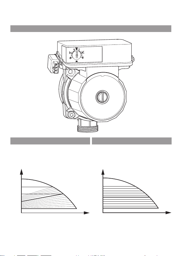
Fig. 1:
Fig. 2a: Fig. 2b:
H max
½ H
H min
H
Q
H
H max
H
H min
Q
Page 3
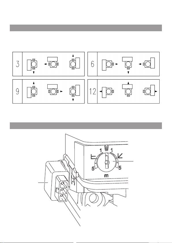
Fig. 3:
Fig. 4:
a
b
1
2
3
Page 4

GB Installation and operating instructions 3
D Einbau- und Betriebsanleitung 13
F Notice de montage et de mise en service 23
I Istruzioni di montaggio, uso e manutenzione 34
RUS Инструкция по монтажу и эксплуатации 45
Page 5

Page 6

English
Installation and operating instructions
1 General notes
About this document
The language of the original operating instructions is German.
All other languages of these instructions are translations of the
original operating instructions.
These installation and operating instructions are an integral
part of the product. They must be kept readily available at the
place where the product is installed. Strict adherence to these
instructions is a precondition for the proper use and correct
operation of the unit.
These installation and operating instructions correspond to the
relevant version of the product and the underlying safety
standards valid at the time of going to print.
EC declaration of conformity:
A copy of the EC declaration of conformity is a component of
these operating instructions.
If a technical modification is made on the designs named there
without our agreement, this declaration loses its validity.
2 Safety
These operating instructions contain basic information which
must be adhered to during installation and operation. For this
reason, these operating instructions must, without fail, be read
by the service technician and the responsible operator before
installation and commissioning.
It is not only the general safety instructions listed under the
main point "safety" that must be adhered to but also the special
safety instructions with danger symbols included under the following main points.
3 WILO SE 05/2011
Page 7
2.1 Indication of instructions in the operating instructions
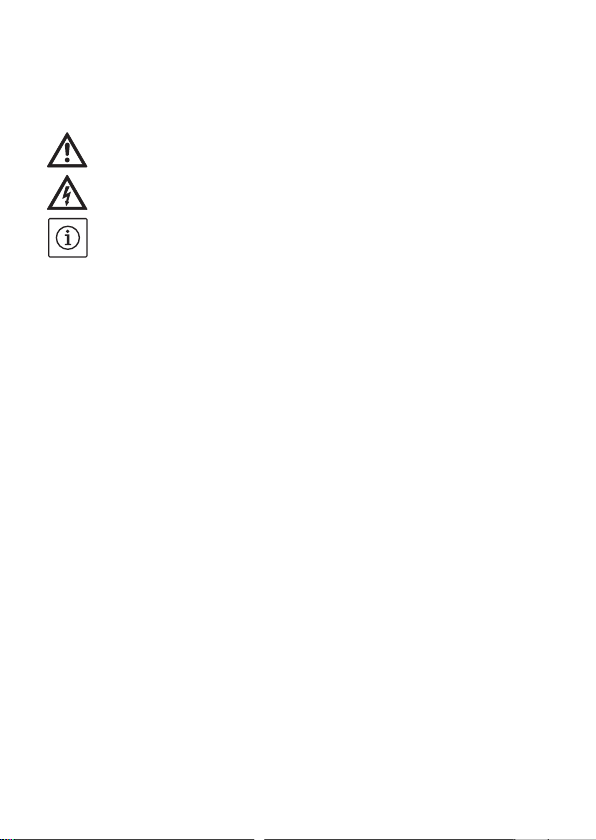
Symbols:
General danger symbol
Danger from electrical voltage
Useful note:
Signal words:
DANGER!
Acutely dangerous situation.
Non-observance results in death or the most serious of injuries.
WARNING!
The user can suffer (serious) injuries. 'Warning' implies that
(serious) injury to persons is probable if this information is
disregarded.
CAUTION!
There is a risk of damage to the product/system. 'Caution'
implies that damage to the product is likely if this information is disregarded.
NOTE: Useful information on handling the product. It draws
attention to possible problems.
English
2.2 Personnel qualifications
The installation personnel must have the appropriate qualifications for this work.
Installation and operating instructions Wilo E.../1-5 4
Page 8

English
2.3 Danger in the event of non-observance of the safety
instructions
Non-observance of the safety instructions can result in risk of
injury to persons and damage to product/unit. Non-observance
of the safety instructions can result in the loss of any claims to
damages.
In particular, lack of care may lead to problems such as:
• Failure of important product/unit functions
• Failure of required maintenance and repair procedures
• Danger to persons from electrical, mechanical and bacteriological influences,
• Property damage
2.4 Safety instructions for the operator
The existing directives for accident prevention must be
adhered to.
Danger from electrical current must be eliminated. Local directives or general directives [e.g. IEC, VDE etc.] and local power
supply companies must be adhered to.
This device is not intended to be operated by persons (including
children) with impaired physical, sensory or mental capacities or
lack of experience and/or lack of knowledge, except in cases
where they are supervised by a person responsible for their
safety or where they receive instructions from such a person as
to how the device is to be operated.
Children must be kept under supervision in order to ensure that
they do not play with the device.
5 WILO SE 05/2011
Page 9

English
2.5 Safety instructions for inspection and installation work
The operator must ensure that all inspection and installation
work is carried out by authorised and qualified personnel, who
are sufficiently informed from their own detailed study of the
operating instructions.
Work on the product/unit should only be carried out when it has
been brought to a standstill. It is mandatory that the procedure
described in the installation and operating instructions for
shutting down the product/unit be complied with.
2.6 Unauthorised modification and manufacture of spare parts
Modifications to the pump/system are only permitted after
consultation with the manufacturer. Original spare parts and
accessories authorised by the manufacturer ensure safety. The
use of other parts can nullify the liability from the results of
their usage.
2.7 Improper use
The operating safety of the supplied product is only guaranteed
for conventional use in accordance with Section 4 of the operating instructions. The limit values must on no account fall
under or exceed those specified in the catalogue/data sheet.
3 Transport and interim storage
Immediately check the product for any transit damage on
arrival. If damage is found, the necessary procedure involving
the forwarding agent must be taken within the specified period.
CAUTION! Risk of damage to the pump!
Danger of damage due to incorrect handling during transport
and storage.
Installation and operating instructions Wilo E.../1-5 6
Page 10

English
• The pump should be protected from moisture, frost and
mechanical damage due to impact during transport and
interim storage.
• The device must not be exposed to temperatures outside the
range of -10 °C to +60 °C.
4 Intended use
The circulation pumps in the E.../1-5 series are designed for
warm water heating systems and similar systems with constantly changing volume flows. Approved fluids are heating
water in accordance with VDI 2035, water/glycol mixture at a
mixing ratio of max. 30 % of glycol. If glycol is added, the delivery data of the pump must be corrected according to the higher
viscosity, depending on the percentage mixing ratio.
5 Product information
5.1 Type key
Example: E 25/1-5-130
E Electronic asynchronous pump
25 Threaded connection DN 25 (Rp 1)
1-5 1 = Minimum delivery head in m
130 Length of pump housing 130 mm
(adjustable down to 1 m)
5 = Maximum delivery head in m
at Q = 0 m³/h
7 WILO SE 05/2011
Page 11

English
5.2 Technical data
Connected voltage 1~230 V +10 %/-15 %, 50 Hz ±5 %
Protection class IP 44 (acc. fig. 3)
Water temperatures + 10°C to + 95°C
Max. operating pressure 10 bar
Max. ambient temperature + 60°C
Min. inlet pressure 0.05 bar at 50°C / 0.3 bar at 95°C
5.3 Scope of delivery
• Circulation pump complete
• Installation and operating instructions
6 Description and function
The pump (fig. 1) consists of a hydraulic system, a glandless
pump motor an electronic control module. The control module
includes a red button for setting all parameters.
7 Installation and electrical connection
Installation and electrical connection must be carried out in
accordance with local regulations and only by qualified personnel!
WARNING! Risk of personal injury!
The existing directives for accident prevention must be
adhered to.
DANGER! Danger of electric shock!
Danger from electrical current must be eliminated.
Local directives or general directives [e.g. IEC, VDE etc.] and
local power supply companies must be adhered to.
Installation and operating instructions Wilo E.../1-5 8
Page 12

English
7.1 Installation
• Only install the pump after all welding and soldering work has
been completed and, if necessary, the pipe system has been
flushed through.
• Mount the pump in a readily accessible place for easy inspection
and dismantling.
• When installing in the supply leg of open systems, the safety
supply must branch off upstream of the pump (DIN EN 12828).
• Install check valves upstream and downstream of the pump to
facilitate a possible pump replacement.
• Perform installation so that any leaking water cannot drip
onto the control module.
• To do this, align the upper gate valve laterally.
• In thermal insulation work, make sure that the pump motor and
the module are not insulated. The condensate drain openings
must remain uncovered.
• Install without tension and with the pump motor in the horizontal position. See fig. 3 for installation positions of the pump.
• Direction arrows on the pump housing indicate the direction of
flow.
• If the installation position of the module is changed, the motor
housing has to be turned as follows:
• Loosen the internal hexagon screws,
• Turn the motor housing, including control module.
CAUTION! Risk of damage to the pump!
The gasket may be damaged when the motor housing is
turned. Replace defective gaskets immediately.
• Twist the internal hexagon screws back in and tighten them,
9 WILO SE 05/2011
Page 13

7.2 Electrical connection
DANGER! Danger of electric shock!
Electrical connection must be carried out by an electrician
authorised by the local electricity supply company and in
accordance with the applicable local regulations [e.g. VDE
regulations].
7.2.1 Electrical connection with Wilo-OEM-Connector
The pump is delivered with the specific Wilo-OEM-Connector
assembled on the electronic module (fig. 4-b):
1 = L1, 1~230 V / 50 Hz
2 = N, neutral conductor
3 = Earth conductor
The mating plug to the OEM plug can be ordered with one of the
following suppliers. (Wilo does not assume any liability for the
products supplied by these manufacturers):
• LTE (www.lte.it)
• FACON (www.facon.it)
7.2.2 Electrical connection with cable
The pump is delivered with a cable assembled on the pump.
The free ends of the cable must be connected in the system
switchbox.
• black/brown wire: L1 (phase)
• blue wire: N (neutral conductor)
• green/yellow wire: PE (earthing)
English
8 Commissioning
WARNING! Risk of burns!
Depending on the pump/system operating conditions (fluid
temperature), the entire pump/system can become very hot.
Touching the pump can cause burns.
Installation and operating instructions Wilo E.../1-5 10
Page 14

English
8.1 Filling and air venting
Fill and vent the system correctly. The pump rotor chamber
normally vents automatically after a short time in operation.
However, if direct venting of the rotor chamber is required, the
air venting routine can be started.
To do this, turn the red button (fig. 4-a) to select the symbol for
air venting. The duration of the bleeding routine is 10 minutes.
Noises may be heard during the air venting routine. The process
can be stopped if desired by turning red button. At the end of
the process, the pump switches automatically to a pre-set
speed. After that, the desired control mode can be set at the red
button.
8.2 Setting the control mode (fig. 2a, 2b) and delivery head
Turn the red button (fig. 4-a) to select the control mode symbol
and adjust the desired delivery height between 1 m and 5 m.
Variable differential pressure (Δp-v): fig. 2a
The differential pressure setpoint is increased linearly over the
permitted volume flow range between ½H and H. The differential pressure generated by the pump is adjusted to the corresponding differential pressure setpoint. This control mode is
especially useful in heating systems with radiators, since the
flow noises at the thermostatic valves are reduced.
Factory setting Δp-v, 5 m
Constant differential pressure (Δp-c): fig. 2b
The differential pressure setpoint is kept constant over the permitted volume flow range at the set differential pressure setpoint up to the maximum pump curve. Wilo recommends this
control mode for underfloor heating circuits or older heating
systems with large-sized pipes.
11 WILO SE 05/2011
Page 15
9 Maintenance
Only allow qualified specialist staff to perform maintenance
and repair work.
DANGER! Danger of electric shock!
Any danger from electrical current should be ruled out.
• The pump should be electrically isolated and secured against
unauthorised switch-on during any maintenance or repair
work.
• Any damage to the connection cable should always be rectified by a qualified electrician only.
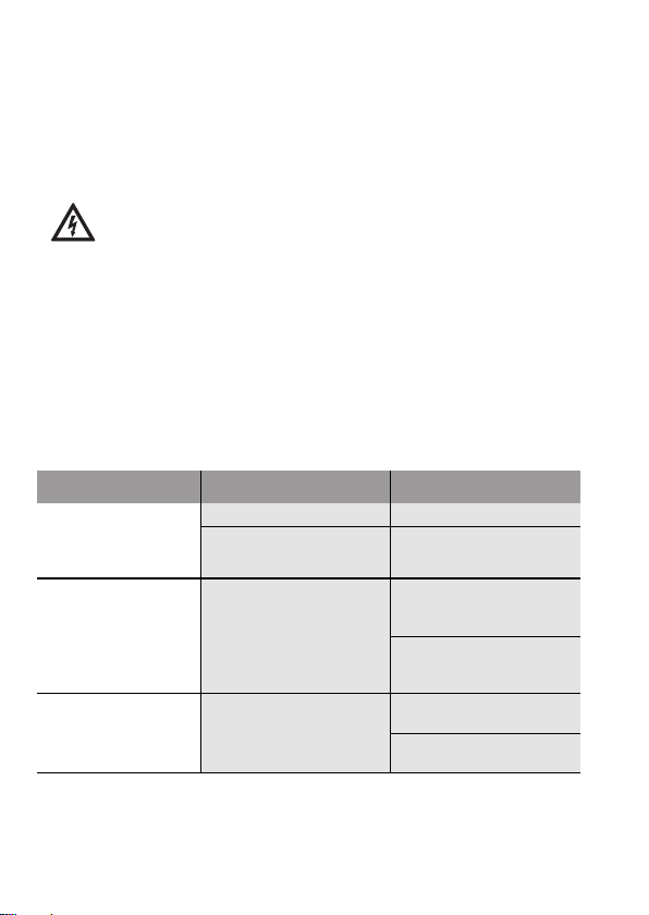
10 Faults, causes and remedies
Faults Causes Remedy
Pump is not running
although the current entry is
switched on
Pump is making
noises
Building does not
get warm
Electrical fuse defective Check fuses.
Pump has no voltage Resolve the power
Cavitation due to insufficient suction pressure
Thermal output of the
heating surfaces is too
low
interruption
Increase the system
suction pressure within
the permissible range
Check the delivery head
and set it to a lower
height if necessary.
Increase setpoint
(see 8.2)
Set control mode to
Δp-c
English
Installation and operating instructions Wilo E.../1-5 12
 Loading...