

Page 1
2044033-Ed.04/2007-05-DDD
Wilo-DrainLift TMP 32-0,5.1
D Einbau- und Betriebsanleitung
GB Installation and Maintenance Instructions
F Notice de mise en service et de montage
I Istruzioni di montaggio, use e manutenzione
Page 2

Page 3
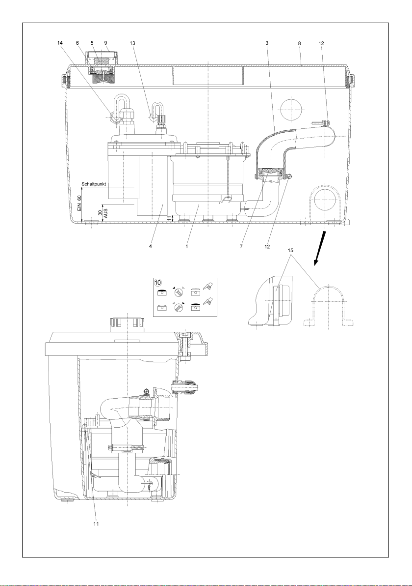
Fig. 1
➩
Page 4
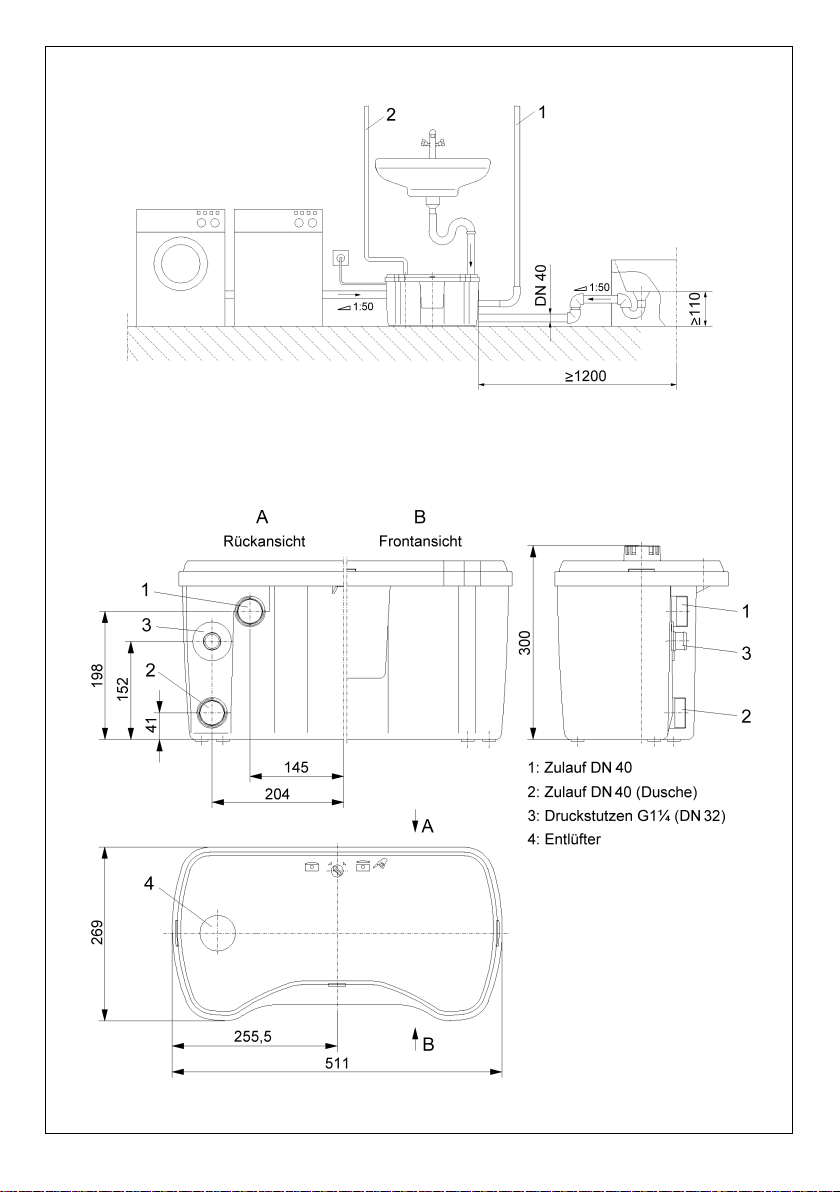
Fig. 2
Fig. 3
Page 5
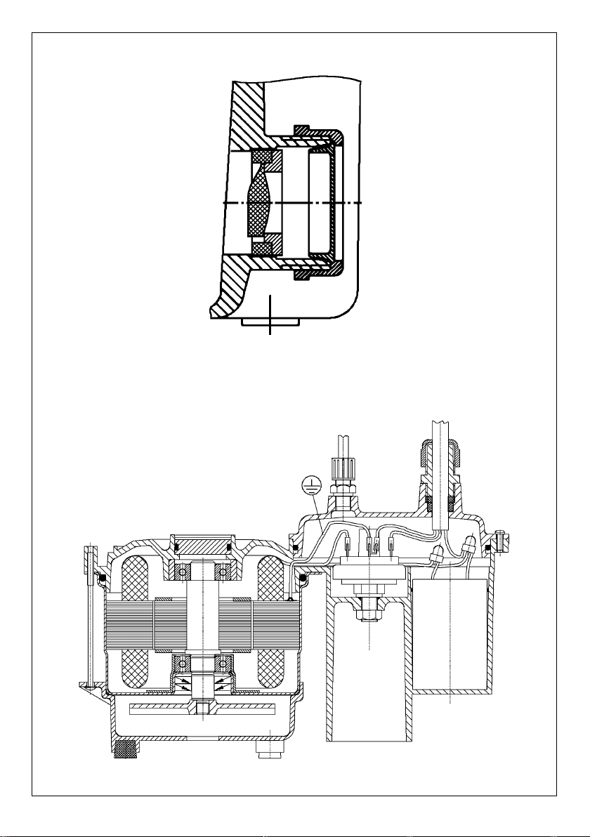
Fig. 4
Fig. 5
Page 6

GB
CE declaration of conformity . . . . . . . . . . . . . 1-2
1. General Information . . . . . . . . . . . . . . . . . . . 8
2. Safety . . . . . . . . . . . . . . . . . . . . . . . . . . . . . . 8
3. Transport and storage . . . . . . . . . . . . . . . . . 9
4. Description of Product . . . . . . . . . . . . . . . . 9
5. Installation . . . . . . . . . . . . . . . . . . . . . . . . . . 10
6. Starting up . . . . . . . . . . . . . . . . . . . . . . . . . . 10
7. Maintenance . . . . . . . . . . . . . . . . . . . . . . . . . 10
8. Problems, Causes and Solutions . . . . . . . . 12
Déclaration de conformité CE . . . . . . . . . . . . . 1-2
1. Généralités . . . . . . . . . . . . . . . . . . . . . . . . . . 13
2. Sécurité . . . . . . . . . . . . . . . . . . . . . . . . . . . . 13
3. Transport et stockage avant utilisation . . . . 14
4. Description du produit . . . . . . . . . . . . . . . . 14
5. Installation/Montage . . . . . . . . . . . . . . . . . . 15
6. Mise en service . . . . . . . . . . . . . . . . . . . . . . 16
7. Entretien . . . . . . . . . . . . . . . . . . . . . . . . . . . . 16
8. Pannes, causes et remèdes . . . . . . . . . . . . 17
CE-Konformitätserklärung . . . . . . . . . . . . . . . 1-2
1. Allgemeines . . . . . . . . . . . . . . . . . . . . . . . . . 3
2. Sicherheit . . . . . . . . . . . . . . . . . . . . . . . . . . . 3
3. Transport und Zwischenlagerung . . . . . . . . 4
4. Beschreibung des Erzeugnissses . . . . . . . 4
5. Aufstellung/ Einbau . . . . . . . . . . . . . . . . . . . 5
6. Inbetriebnahme . . . . . . . . . . . . . . . . . . . . . . 6
7. Wartung . . . . . . . . . . . . . . . . . . . . . . . . . . . . 6
8. Störungen, Ursachen und Beseitigung . . . 7
D F
Dechiarazione CE di conformità . . . . . . . . . . . 1-2
1. Generalità . . . . . . . . . . . . . . . . . . . . . . . . . . . 18
2. Sicurezza . . . . . . . . . . . . . . . . . . . . . . . . . . . 18
3. Transporto e magazzinaggio . . . . . . . . . . . . 19
4. Descrizione del prodotto . . . . . . . . . . . . . . . 19
5. Installazione/Montaggio . . . . . . . . . . . . . . . 20
6. Messa in servizio . . . . . . . . . . . . . . . . . . . . . 21
7. Manutenzione . . . . . . . . . . . . . . . . . . . . . . . . 21
8. Disfunzioni, cause e rimedi . . . . . . . . . . . . . 22
I
Page 7

D CE-Konformitäts-
erklärung
Hiermit erklären wir, dass
dieses Aggregat folgenden
einschlägigen Bestimmungen
entspricht:
EG-Maschinenrichtlinien
89/392/EWG i.d.F.,
91/368/EWG, 93/44/EWG,
93/68/EWG
Elektromagnetische
Verträglichkeit
89/336/EWG i.d.F.
92/31/EWG, 93/68/EWG
Angewendete harmonisierte
Normen, insbesondere
EN 809, EN 50 081-1,
EN 50 082-1, EN 50 081-2,
EN 50 082-2.
GB EC declaration of
conformity
We hereby declare that this
unit complies with the
following relevant provisions:
EC machinery directive
89/392/EWG in this version,
91/368/EWG, 93/44/EWG,
93/68/EWG
Resistance to
electromagnetism
89/336/EWG in this version
92/31/EWG, 93/68/EWG
Applied harmonized
standards in particular:
EN 809, EN 50 081-1,
EN 50 082-1, EN 50 081-2,
EN 50 082-2.
F Déclaration de
conformité CE
Par la présente, nous
déclarons que cet
agrégat sitisfait aux
dispositions suivantes:
Directives CEE relatives
aux machines 89/392/CEE,
91/368/CEE, 93/44/CEE,
93/68/CEE
Compatibilité
électromagnétique
89/336/CEE, 92/31/CEE,
93/68/CEE
Normes utilisées
harmonisées, notamment
EN 809, EN 50 081-1,
EN 50 082-1, EN 50 081-2,
EN 50 082-2.
NL EG-verklaring van
overeenstemming
iermede verklaren wij dat
deze machine voldoet aan
de volgende bepalingen:
EG-richtlijnen betreffende
machines 89/392/EEG,
91/368/EEG, 93/44/EEG,
93/68/EEG
Elektromagnetische
tolerantie
89/336/EEG, 92/31/EEG,
93/68/EEG
Gebruikte geharmoniseerde
normen, in het bijzonder
EN 809, EN 50 081-1,
EN 50 082-1, EN 50 081-2,
EN 50 082-2.
E Declaración de
conformidad CE
Por la presente declaramos
que esta unidad satisface las
disposiciones pertinentes
siguientes:
Directivas CE sobre
máquinas 89/392/CEE,
91/368/CEE, 93/44/CEE,
93/68/CEE
Compatibilidad electromagnética 89/336/CEE,
92/31/CEE, 93/68/CEE
Normas armonizadas
utilizadas particularmente
EN 809, EN 50 081-1,
EN 50 082-1, EN 50 081-2,
EN 50 082-2.
I Dichiarazione di
conformità CE
Con la presente si dichiara
che le presenti pompe sono
conformi alle seguenti
direttive di armonizzazione
Direttiva Macchine CEE
89/392/CEE, 91/368/CEE,
93/44/CEE, 93/68/CEE
Compatibilità
elettromagnetica
89/336/CEE, 92/31/CEE,
93/68/CEE
Norme armonizzate
applicate, in particolare
EN 809, EN 50 081-1,
EN 50 082-1, EN 50 081-2,
EN 50 082-2.
SF CE-standardinmukai-
suusseloste
Ilmoitamme täten, että tämä
laite vastaa seuraavia
asiaankuuluvia määräyksiä:
EY-konedirektiivit
89/392/ETY, 91/368/ETY,
93/44/ETY, 93/68/ETY
Sähkömagneettinen
soveltuvuus
89/336/ETY, 92/31/ETY,
93/68/ETY
Käytetyt yhteensovitetut
standardit, erityisesti
EN 809, EN 50 081-1,
EN 50 082-1, EN 50 081-2,
EN 50 082-2.
S EEC konformitets-
deklaration
Härmed förklaras att denna
maskin uppfyller följande
bestämmelser:
EEC maskindirektiv
89/392/EEC i denna version,
91/368/EEC, 93/44/EEC,
93/68/EEC
Elektromagnetisk
kompatibilitet 89/336/EEC i
denna version, 92/31/EEC,
93/68/EEC
Tillämpade harmoniserade
normer, särskilt:
EN 809, EN 50 081-1,
EN 50 082-1, EN 50 081-2,
EN 50 082-2.
H EK. azonossági
nyilatkozat
Ezennel kijelentjük, hogy
az agregát a megkívánt
alanti feltételeknek
megfelel:
EK-Gépirányelvek
89/392/EWG, 91/368/EWG,
93/44/EWG, 93/68/EWG
Elektromagnetikus
ÖsszeegyeztethetŒség
89/336/EWG, 92/31/EWG,
93/68/EWG
Alkalmazott, harmonizált
normák, különösen az
EN 809, EN 50 081-1,
EN 50 082-1, EN 50 081-2,
EN 50 082-2.
1
Page 8

ENGLISH
8
Safety precautions for the operator
Reading the operating instructions makes it easier
to operate the unit and to understand the operating
sequence.
We are also obliged to draw your attention to the
necessity of adhering to the safety instructions given throughout the installation and operation instructions.
Adjustments, maintenance work and repairs
should only be carried out by an expert or by Wilo
customer services.
The unit's functions are all automatic. It is not necessary to service the unit.
1 General Information
Assembly and installation should only be carried
out by qualified personnel!
1.1 Uses
As an automatic sewage water lifting unit for the sanitation of showers, basins, washing machines and
dishwashers in both old and new buildings, whose
dirty or waste water cannot be transported into the
canal system by the natural downward gradiant
and must therefore be lifted above the damming up
level. This unit is particularly suitable for the sanitation of washing machines and showers in cellars.
As a waste water lifting unit for the transportation of
sewage and fibre-free, non-aggressive waste water.
The norm DIN EN 12050-2, DIN EN 12056 and DIN
1986-100 must be observed when operating the
unit.
This lifting unit is not suitable for transporting waste
water which contains solid sewage.
1.2 Connection and output data
– Max. transporting capacity: 4,5 m
3
/h
– Maximum lift: 6,5 m
– Max. flow medium temp.: 45 °C when in
constant use,
Washing machine
and dishwasher
waste water may
also reach 75°C
for short periods
of time.
– Max. size of grains or solids.: 10 mm
– Voltage / Frequency: 1~230 V, 50 Hz
– Capacity: 0,33 kW
– Nominal current: 1,5 A
– Type of operation: Constant use S1
in acordance with
DIN, VDE 0530 T1
– Protective system: IP 44
– Delivery connection: DN 32
– Supplies: 2 x G 1
1
/2 (DN 40)
in accordance
with DIN 1986
incl. blind cover
and sealing ring
– Ventilation: 25 mm outer dia-
meter
– Measurements W x H x B: 511 x 300 x 269
mm
– Useful volume: 12 l
– Weight: 7,1 kg
When ordering spare parts, all details on on the rating plate should be given.
2 Safety
These instructions contain important information
which must be followed when installing and operating the pump. It is therefore imperative that they be
read by both the installer and relevant operators
before the pump is assembled and operated. Both
the general safety points in this section and the
more specific safety points in the following sections
should be noted.
2.1 Instruction symbols in this operating manual
Safety precautions in these operating instructions
which, if not followed, could cause personal injury
are indicated by the symbol:
,
Safety precautions warning of danger due to electricity are indicated by the symbol:
Safety precautions which, if not followed, could damage the pump or installation and cause it to malfunction are indicated by the word:
2.2 Staff training
The personnel installing the pump must have the
appropriate qualifications for this work.
ATTENTION!
Page 9

ENGLISH
9
2.3 Risks incurred by failure to comply with the
safety precautions
Failure to comply with the safety precautions could
result in personal injury or damage to the installation. Failure to comply with the safety precautions
could also invalidate any claim for damages.
In particular, failure to comply with these safety precautions could give rise, for example, to the following risks:
– the failure of important parts of the installation,
– Personal injury due to electrical, mechanical and
bacteriological causes,
– Personal injury and damage to the environment
due to failure to comply with hygiene regulations
when handling media liable to cause infection.
2.4 Safety precautions for the operator
Current regulations on the prevention of accidents
must be observed.
Injury resulting from electrical charges must be
avoided. The VDE (German association of Electrical
Engineers) and national energy supply company
regulations must be observed.
2.5 Safety information for inspection and assembly
The operator must ensure that all inspection and installation work is carried out by authorised and
qualified specialists who have carefully studied
these instructions.
In principle, work should not be carried out on a
running pump or installation.
2.6 Unauthorised alterations and spare parts
Alterations to the pump or installation may only be
carried out with the manufacturer's consent. The
use of original spare parts and accessories authorised by the manufacturer will ensure safety. The
use of any other parts may invalidate claims invoking the liability of the manufacturer for any consequences.
2.7 Improper use
The operating safety of the pump or installation
supplied can only be guaranteed if it is used in accordance with paragraph 1 of the operating instructions. The limiting values given in the catalogue or data sheet must neither be exceeded nor
allowed to fall below those specified.
3 Transport and storage
– Care should be taken during transport that the
unit is not damaged by impact against other objects.
– The unit should be stored in a dry, frost-free
place.
4 Description of product
4.1 Description of unit
The automatic waste water lifting unit (fig. 1) comprises a plastic gas and waterproof collector tank
which is placed on the ground (as low as possible),
e.g. beneath a basin.
The connections (fig. 3, pos. 1/2) for the drainage
points and also for the compressed air piping (fig.
3, pos.3) are located at the back of the cistern. The
space behind the unit makes it easier to lay pipes.
In this way, the supply channels and the compressed air piping can be connected from both sides.
Where there are more than two drainage points, the
connection can be made by branching the supply
channel in two.
Care should be taken that waste water does not
flow out of all drainage points at the one time.
The pump which is built into the cistern (fig. 1, pos.1,
fig. 5) drops into the waste water when the cistern
is full. The motor is sealed and waterproof. The motor shaft has been sealed two times to the pump.
The motor coil is protected by an overload safety
device which automatically switches off the motor if
it is subjected to excessive strain. After the motor
has cooled down, it is automatically switched back
on again.
The built-in booster relay (fig. 1, pos.4) switches the
unit on and of, depending on the level.
The activated carbon filter integrated into the unit
(fig. 1, pos.5) enables airing and ventilation to take
place directly in the installation room or by means
of an aeration pipe on the roof which should be
connected separately. In order to prevent the collection tank from overflowing through the activated
carbon filter in the event of pump failure and an increase in the fluid level, an additional flap trap (fig.
1, pos.6) has been added. The drain connection
also contains a flap trap (fig. 1, pos.7).
4.2 Products delivered
– Waste water lifting unit
– extra set: fixing pipe-clip, sealing rings, union
nuts, thrust collars and blind covers.
– Installation and Operating Instructions
Page 10

ENGLISH
10
5 Installation
5.1 Assembly
– The unit should be installed in a frost-free room.
– Install in a horizontal and flat position.
– The lifting unit and the electrical connection
(plug) must remain accessible for maintenance
even after assembly.
– For installation diagram, see Fig. 2.
– For main measurements, see fig. 3.
– Connect the supply channels to the drainage po-
ints (fig. 3, pos 1/2). The union nuts, the thrust
collar and the sealing ring provided should be
pushed onto the supply channel (outer diameter
- 40 mm, conventional PVC pipe). Push the PVC
pipe into the supply channel connection pipe
and screw the union nut tightly onto the inlet con-
nection pipe. Do not seal the inlet at the thread.
The unused inlet opening must be locked with
the cowl provided:
– Push the pressure ring onto the cowl,
– Slide on the seal cross section form: three si-
ded) with the wide edge pointing to the pressure ring.
– Lay the cowl in the union nut and screw onto
the supply channel opening.
The additional side supply channels (DN 40) must lie above the
highest possible water level (180
mm). For this reason, the construction level (base) of the
shower basin must lie at least
180 mm higher than the construction level of the mini lifting
unit (fig. 2). The shower surface
may be reduced to 110 mm above
the construction level when
installing Viega-domoplex discharge fittings, when the distance
between the lifting unit and the
shower is equal to or larger than
1,200 mm.
– The flap trap (fig. 4) is pushed into the lower sup-
ply channel (fig. 3, pos.2) opening as far as the
limit stop in such a way that the trap is open to
the cistern. Then, push in the supply pipe as des-
cribed above (the use of the trap is not permis-
sable in Germany).
– It is recommended that a shut-off device be in-
stalled in the pressure pipeline. It must be suita-
ble for waste water which contains sewage and
should be assembled on site.
ATTENTION!
– Connect pressure pipeline (fig. 2, pos.1, min.
diameter - DN 25 / connection: fig. 3, pos.3)
upwardly onto the collector pipe.
– If the pressure pipeline runs horizontally off cen-
tre, it must be laid with a loop (U-shaped stench
trap) when it comes out of the unit.
– In order to protect against possible reflux out of
the public channel, the pressure pipeline should
be formed as a „pipe loop“ (U-shaped). It must
be placed over the locally set reflux level (usually street level).
– If ventilation takes place through a vent connec-
tion in the roof rather than through the activated
carbon filter which is integrated into the unit, the
cap (fig. 1, pos. 9) should be removed from the
ventilation and the vent connection (fig. 2, pos. 2,
inner diameter 25 mm, comercially available PVC
pipe) should be pushed by a flexible piece of
hose onto the support. The activated carbon filter (fig. 1, pos. 5) can be removed.
– The unit must be secure against buoyancy. To do
this, push the enclosed pipe clip (fig. 1, pos.15)
over the supply chanel and fix it to the ground
with pins and screws.
5.2 Electrical connection
Electrical connection should be made
by a qualified electrician. Current national regulations must be observed (e.g.
VDE regulations in Germany).If the units
power cable is damaged it must be replaced by the customer service or a similar qualified person.
– Check that the mains current and voltage com-
ply with the data on the rating plate.
– Pump/installation must be earthed in compli-
ance with regulations.
– Mains fuse: 10A time-lag fuse.
6 Starting up
– Plug in shock-proof plug,
– Let the water flow in until the pump starts up,
– Chek all pipe connections for leakages.
7 Maintenance
The pump should be checked regularly to ensure
that it functions perfectly and quietly. By doing so,
large faults can be avoided. Regardless of the content of the fluid, the pump should be checked and
cleaned at least once a year.
Page 11

ENGLISH
11
7.1 Maintenance and care of the unit (fig. 1)
– Allow the water to flow in and pump the cistern
until it is empty,
Pull out the plug before checkin
the unit!
– Remove covering cap (fig. 1, pos. 8) by using the
tommy bar (fig. 1, pos. 10) and pressing the 3
snap hooks (side and front).
– Remove any impurities from the walls of the ci-
stern.
– Clean went pipe or ventilating valve, renew acti-
vated carbon filter.
– Re-assemble in the opposite order.
7.2 Dismantling the pump (Fig. 1)
Flusihing, opening the unit and observing warning
symbols as described in 7.1.
– Unscrew the 3 screws which fasten the motor
(fig. 1, pos.11),
– Unsrew the upper hose-clip (fig. 1, pos.12) on the
discharge connection,
– Unscrew the screw of the ventilation pipe (fig. 1,
pos.13) on the cistern wall and pull off the venti-
lation pipe.
– Unscrew the connection cable PG screw joint
(fig. 1, pos.14) on the tank wall and pull the cable
through to the inside of the cistern,
– If the pump is to be taken out of the tank com-
pletely, unscrew the electric plug and take the
cable out of the PG screw joint,
– Take out the pump with booster relay and elec-
trical connection,
– Clean the booster relay,
– Assemble the components in the opposite order,
– Carry out a test run.
Should the pump need to be returned to
Wilo for repairs, all used units must be
emptied and cleaned prior to transport
for reasons of hygiene. Furthermore, all
parts which are likely to be handled
must be disinfected (spray disinfection).
The parts must be sealed carefully in
sufficiently large, robust, plastic sacks
and must be packed in such a way that
no fluid can leak out. The packages
must be sent immediately by a wellknown, trustworthy courrier service.
Page 12

ENGLISH
12
8 Problems, Causes and Solutions
Problem Cause Solution
Motor does not run No supply voltage Check main fuse, FI switch and supply cable
Fuse defect Change fuse and, if necessary, eliminate cause of
fuse blow
Overload switch Temp. of flow medium to high, keep with in the
triggered on permissible temperature range. If the event of
reoccurrence, contact customer service.
Pump blocked, contact customer service
Overload switch
triggered on
Booster relay defect contact customer service
Motor defect contact customer service
Motor runs, pump Pressure pipeline blocked Remove blockage or brucking, carry out test run
does not function or buckled
Valve in pressure pipeline open valve
closed
Unit ventilation blocked Remove ventilation pipe and clean or replace
activated carbon filter
Pump does not Impeller damaged or Clean impeller or replace
function properly dirty
Pipeline blocked Remove blockage
Lift or loss of pressure too Use pipeline with a larger diameter
high,
incorrect dimensioning
Pump runs in short Ventilation blocked Clean ventilation
intervals Leak in flap trap Clean or replace
Motor makes loud Foreign body in the unit Dismantle pump and clean or contact customer
noises when rotating services
If the fault cannot be remedied, please contact your plumbing and heating specialist or your
nearest WILO customer services or representative.
Subject to technical alterations!
Page 13

Page 14

 Loading...