

Page 1
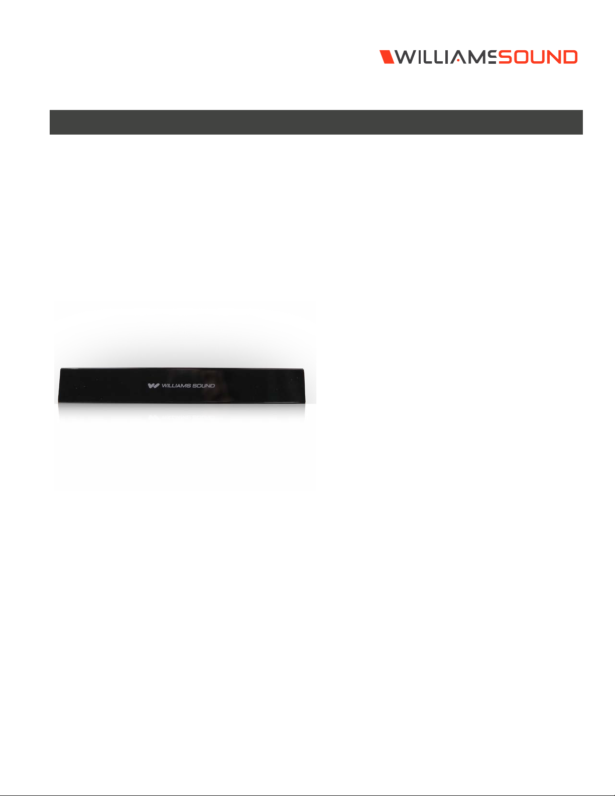
IR T2
Infrared Transmitter
SPECIFICATION DATA
Courtrooms • Conferences • Houses of Worship • Universities • Cinema
The IR T2 infrared transmitter ensures participants in your
conference room, courtroom, classroom or other mid-sized venue
receive direct, clear communication of your message without
sacrificing security. The sleek and stylish IR T2 is designed to
maximize coverage area up to 18,000 square feet* (1672 m) in
single-channel mode when using the RX22-4 receiver. Mounting
bracket and international power supply are included. 5-year
warranty.
System includes:
(1) IR T2 infrared transmitter
(1) BKT 024 wall / ceiling mounting bracket
(1) TFP 057 (or TFP 061 with certain systems) international power
supply with line cord
*Operating range varies based on receiver used. Reference user
manuals or contact TechBlue at [email protected] for
specific coverage information.
© 2020, Williams AV, LLC MCAT 243D
Page 2
IR T2 Infrared Transmitter
IR T2 Specifications
Dimensions, Weight: 9.0" W (229 mm) x 3.8" D (97 mm) x 1.4" H (36 mm), 0.84 lb. (0.38 kg)
Color: Black
Power Supply: TFP 057 (or TFP 061 with certain systems) Desktop style international certified power supply with IEC line cord, 100-240 VAC input, 50-
DC Power Input: 2.1 mm ID barrel connector, 48 VDC, 0.2A, center positive
Power Indicator: Green LED
Sleep/Power Save Mode: Shuts o carrier when no audio is present for 12 minutes
Modulation: FM Wideband, ±50 kHz deviation max, 50 μS pre-emphasis
Emitter IR Power: 0.7 W
Baseband Frequencies: 2.3, 2.8, 3.3, 3.8 MHz
Channels: Indicators: Yellow LEDs indicate whether 2.3/2.8 MHz or 3.3./3.8 MHz baseband frequencies are selected
Coverage Area: Up to 18,000 sq. ft (1,673 sq. m) in single-channel mode with the RX22-4 receiver
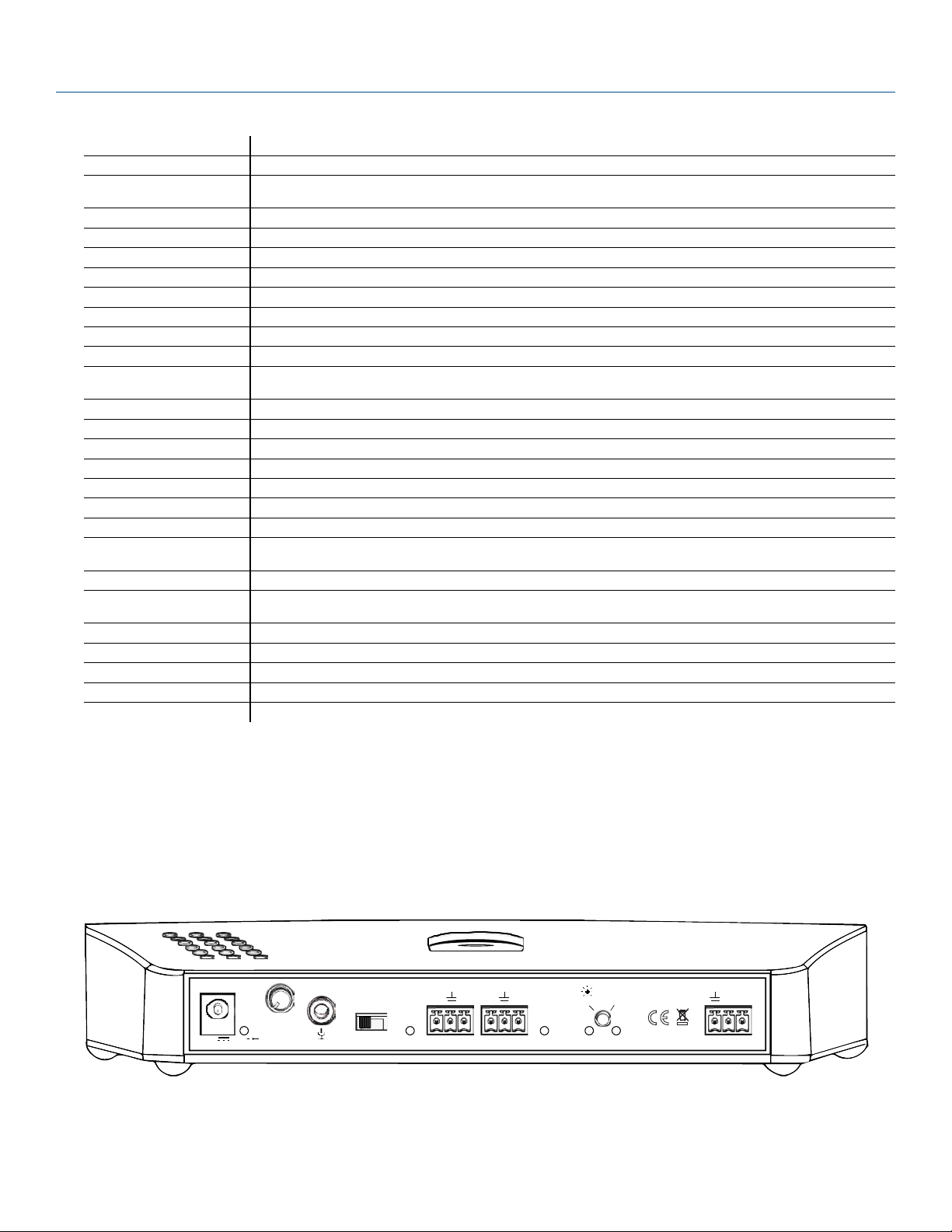
Microphone input: 3.5 mm, stereo jack with signal and bias connected to tip, electret microphone compatible (6 VDC bias supply with 2.7 k ohm series
Microphone gain adjust: Rotary 10 dB range
Microphone channel switch: Selects microphone input to Ch. A or Ch. B
Audio Inputs / Controls: Line inputs: Phoenix style connector jack for Ch A and Ch B accept line level, balanced or unbalanced audio
Audio indicators: One yellow LED per channel. Lights up and stay on steady with minimum audio level.
Indicators On/O: Momentary contact switch turns on/o indicator lights
Frequency Selection: Press and hold momentary contact switch to change carrier frequency group.
Signal-to-Noise Ratio: 70 dB (line input)
Frequency Response: 95 Hz to 17.6 kHz, -3 dB re 1 kHz (line inputs)
Total Harmonic Distortion: <1% (1 kHz, nominal deviation, line or microphone input)
Control/Monitoring: 3-wire RS-232 bus, standard ASCII commands/replies, 115200 Baud rate (8N1).
Operating Requirements: 32°-122°F (0-50°C)
Mounting Kit: Wall or Ceiling mount: BKT 024 Omnidirectional mount
Warranty: 5 Years
Approvals: CE, FCC, Industry Canada, WEEE, RoHS, CB Scheme, RCM, PSE
Compatible Receivers: WIR RX22-4, WIR RX18, IR R1
60 Hz, 18 W; 48 VDC output
resistor)
125 Hz to 17.0 KHz, -3 dB re 1 kHz (microphone input)
See the IR T2 Programmers Guide for more information.
POWER IN
48VDC
CH A CH B
- -
-
+
MIC GAIN
0.2A
-
+
C
MIC CH
A
B
LINE IN LINE IN
++
PRESS
2.3/2.8
MHz
MHz
HOLD
3.3/3.8
CONTROL
Tx Rx
Page 3

IR T2
Architectural Engineering Specs
IR T2
The Williams Sound infrared transmitter shall consist of an all in one modulator and emitter operating on 2.3 MHz and/or 2.8 MHz (or 3.3
and/or 3.8 MHz) broadband frequency. The carrier frequency shall use 50 kHz deviation and 50 µS pre-emphasis.
The transmitter will operate in 2 channel mode on broadband frequencies 2.3 and 2.8 or on 3.3 and 3.8 MHz.
The transmitter will operate in single channel mode on broadband frequency 2.3, 2.8, 3.3, or 3.8 MHz.
The transmitter shall have coverage up to 18,000 sq ft (1672 m) with the WIR RX22-4 receiver in single-channel mode.
The transmitter shall be housed in a heavy-duty black plastic enclosure with a metal plate base, and a durable infra-red transparent front lens. It
shall be convection cooled without fans. The Transmitter includes an omni-directional mounting bracket for various permanent installations.
The transmitter shall have a line level Phoenix style connector input for each of the channels. Each channel shall have an audio input level
LED. There shall be a single 3.5 mm microphone input with gain control. The mic input shall have a channel selector switch.
The transmitter shall have a switch to turn o all indicator LED’s if pressed, and change the carrier frequency set if pressed and held.
The transmitter shall be powered by a 48 VDC universal power supply, 50-60 Hz, 100-240 VAC input, 18 W.
The transmitter shall have RS-232 monitoring and control available for third party controllers.
The transmitter shall be covered by a five-year parts and labor warranty, 90 days on accessories.
The transmitter operating at 2.3 and/or 2.8 (or 3.3 and/or 3.8 MHz) shall be the Williams Sound model IR T2.
NOTE: SPECIFICATIONS SUBJECT TO CHANGE WITHOUT NOTICE!
Domestic Sales
Williams AV
10300 Valley View Rd
Eden Prairie, MN 55344
Ph: 800-328-6190 / 952-943-2252
FAX: 952-943-2174
Email: [email protected]
Web: www.williamsav.com
International Sales
International Sales Department
Williams AV
10300 Valley View Rd
Eden Prairie, MN 55344 USA
Phone: +1 952 943 2252
Fax: +1 952 943 2174
Email: [email protected]
Web: www.williamsav.com
[email protected] / www.williamsav.com
800-843-3544 / INTL: +1-952-943-2252
© 2020, Williams AV, LLC MCAT 243D
 Loading...