

Page 1

by
INSTALLATION and OPERATING MANUAL for
REACH-IN and ROLL-IN BLAST CHILLERS
This manual covers the installation, operation and routine maintenance requirements for the following products:
Reach-In Models: WBC35, WBC60, WBC75 & WBC110
Roll-In Models: WMBC175, WMBC220, WMBC350, WMBC480 & WMBC660
Provided the instructions in this Operating Manual are read and implemented correctly, the optimum performance
and reliability of your equipment should be maintained.
Page 2

TABLE OF CONTENTS
Page 2 SECTION 1 - GENERAL OPERATION & MAINTENANCE
Page 3 Receiving Shipment
Unpacking
Installation
Electrical Supply
Page 4 Start-Up
Principles of Operation
Loading and Packing
Food Storage Time
Operation of Blast Chillers
Blast Modes
Page 5 Blast Modes (continued)
Blast Chill Cycle Programming and Operation
Page 6 Blast Chill Cycle Programming and Operation (continued)
Defrost
Alarms
Page 7 Alarms (continued)
Door Operated Fan and Condensing Unit Cut-Out Switches
Airflow
Compressor Control
Page 8 Thermostats and Probes
Data Logger and Printer
Miscellaneous Functionality
Page 9 Maintenance
Cleaning
Door Gasket
Service and Replacement Parts
Page 10 Rules of Thumb
Page 11 Before Calling Service Guide (for Common Problems)
Page 12
Pages 13 - 18 Specification
SECTION 2 - WILLIAMS DATA LOGGER WITH PRINTER MODULE
Operation Overview
Display Screens and Button Operation
Page 19
Pages 20 - 35 Parts Lists
Pages 36 - 44 Wiring Diagrams
Pages 45 - 47 Controller Set-Up
SECTION 3 - PARTS LISTS / WIRING DIAGRAMS / CONTROLLER SET-UP
2
Page 3

RECEIVING SHIPMENT
All units are performance tested and thoroughly inspected
prior to shipment. Upon leaving the factory all units are in
perfect condition. During the receipt process, examine the
exterior of the shipment packaging for any signs of rough
handling. If the cabinet is damaged, it should be noted on
the delivery slip orbill or lading and signed. A claim must be
filed immediately against the carrier indicating the extent and
estimated cost of damage incurred.
UNPACKING
Remove all external and interior packing and accessories.
Ensure all packaging is disposed of safely.
Locking Casters
When a reach-in cabinet has been placed in a desired
location, please ensure brakes have been placed into the
“lock” position by pressing the metal bar down. Remember
to release the brakes before trying to move the cabinet.
Pan Slides & Shelves:
When positioning the slides, present the slide to the racking
by holding it in the opposite hand to the side of the cabinet
you are installing the slides. Position the slide at a 45°
(degree) angle as shown in Figure 1. Once in place, let the
slide drop into position creating a horizontal ledge on which
pans or shelves will sit.
INSTALLATION
Proper installation is the first step to good operation. We
recommend that your blast chiller be installed by alicensed
commercial refrigeration service company.
Reach-In & Roll-In Cabinets:
The cabinet should stand level to ensure correct operation of
self closing doors and proper drainage of condensate from
the evaporator.
Models fitted with casters are non-adjustable, therefore a
level platform/floor should be provided where the cabinet is
to be located. On models fitted with adjustable legs leveling
may be achieved by adjustment of the bottom section of the
legs.
For top mounted refrigeration systems, please ensure there
is 20” (500mm) between the top of the cabinet and ceiling for
service technician access and ventilation.
If a reach-in cabinet with a self-contained top mounted
refrigeration has been laid on its back or tipped, DO NOT
switch “ON” immediately. Leave the cabinet in the upright
position for at least 12 hours before switching “ON”.
Ventilation
It is essential to ensure that the room in which the
cabinet is installed is adequately ventilated. Refrigerators /
Chillers generate considerable amounts of heat and, if
operated in small unventilated room, especially in warm
weather,this will quickly cause the room temperature to rise.
Thiscouldcausethemotortooverheatandpossibly damage
the windings. At thevery least, such an installation will cause
the cabinet to use an excessive amount of electricity.
Fig. 1
ELECTRICAL SUPPLY
Wiring should be done by a qualified electrician in
accordance with local electrical codes. All models with the
exception of the WBC110, WMBC175, WMBC220,
WMBC350, WMBC480 & WMBC660 come fitted with a
NEMA plug for safety, and must be grounded. The
WMBC110 and WMBC’sare 3-phase and require connection
to a suitable supply.
Voltage supplied to the cabinet must be between 208
Volts to 230 Volts only; no exceptions! WARRANTY IS
NOT VALID OUTSIDE THE LIMITS OF 230 VOLTS! A
surge protector is highly recommended for added protection.
Note: Please take extra precaution when cabinet is being
supplied voltage to a Delta Circuit).
3
Page 4

START-UP
Main Control Breakers
Should the equipment fail to run on initial connection, please
check that all Main Control Breakers (MCBs) are in the “ON”
position at the back of cabinet. Note: The “ON” position is
confirmed by red indicators on the MCBs.
Thermometer
The controllerismarkedin Fahrenheit(°F)orCentigrade(°C)
for the thermometer display. The thermometer should be
checkeddailyto ensure that the equipment is maintaining the
correct temperature.
If the cabinet is operating at the wrong temperature due to a
default, the cabinet will alarm.
PRINCIPLES OF OPERATION
Williams blast chillers have been designed to quickly reduce
the temperature of food in accordance with Department of
Health guidelines on the chilling of cooked foods. All
operators should be conversant with Department of Health
publication,ChilledandFrozen Guidelineson Cook-Chill and
Cook-Freeze Catering Systems.
Fast temperature reduction is not brought about by placing
the food in a very cold cabinet like a deep freeze. This would
only dry the food badly and take a very long time to reduce
its temperature to the required level. The secret of fast
temperature reduction is in delivering the correct blast of air
and ensuring correct and unobstructed horizontal air flow
inside the cabinet. This is why the equipment has the option
of soft and hard facility on blast chill.
are good conductors. Plastic or polyurethane containers
insulatethe food from the cold air. When chilling unportioned
food we recommend the use of the appropriate pan that is at
1
least 2
covers on food will also increase the chilling time but may be
of some use when processing some delicate foods to avoid
dehydration.
Always load your machine in such a way that it is possible
for the cold air to contact all sides of the containers. Avoid
stacking containers directly on top of one another as this will
drastically extend the chilling time and take special care not
to block the air ducts.
Always load the machine before selecting the blast cycle.
Unless it is unavoidable do not open the door of the machine
while the blast cycle is engaged.
In the case of roll-in rack models, bumper bars are fitted to
the walls inside the machine. This assists in the correct
positioning of the rack(s) so as to avoid blocking the air flow.
/2” (63.5mm) in depth. Likewise, placing lids or
FOOD STORAGE TIME
Chilled foods can be stored for up to 5 days at between 32°F
(0°C) and 38°F (3°C).
OPERATION OF BLAST CHILLERS
Thecabinetisdelivered readyto run. Plug (or connect)to the
main power supply and the cabinet is ready for use. Initially
the cabinet will be in standby mode, shown by 3 dashes
( - - -) in both display windows. The cabinet needs to be
pre-chilled (or ran) for at least 30 minutes before being used.
Exceptions: depending on the density types and sizes
of the portions the chiller might not be capable of
achieving the required guidelines, therefore, the load
and/or depth of the food layers should be reduced. You
may find it necessary to experiment with different
amounts of food and loading methods in order to
achievethe optimumperformance with your blast chiller.
LOADING AND PACKING
Regulations state that product should be placed in the Blast
Chiller within 30 minutes from completion of cooking. The
packaging of food and the way in which it is loaded or placed
within the apparatus can have a significant effecton the time
within which the temperature can be reduced to the required
leveland the amount offood which can be processedin each
chilling batch.
When blast chilling always use metal or foil containers which
Note: The control systems employed contain no user
serviceable components. Instructions on setting up the control panel thermostats are available from the manufacturer.
These should only be reset by a qualified service technician.
3 BASIC MODES
Timed Cycle Blast
This is the storage temperature at which food can be held
and the blast chiller automatically switches into this mode at
the end of each cycle. Normal storage temperature range is
34°C (1°C) to 37°F (3°C).
Storage Mode
During store mode (with no alarm condition or defrost cycle
running) the left hand window will display the previous blast
cycle duration and the right hand window will display the
store temperature. Some chillers have more than 1 fan
installed; these may not all operate during the storage mode,
4
Page 5
giving a reduced air circulation within the chiller.
From store mode the following functions can be achieved:
1. Go into standby mode by pressing and holding for
3 seconds.
2. Initiate the setting of a blast chill by pressing
4. After a short delay, the LED relevant to the probe that
has been reinserted into the newly introduced product
will illuminate once again to indicate that it is attempting
to achieve its target temperature (chilling the product)
once more.
The blast cycle will only end once all food probes have
achieved the target temperature simultaneously.
3. Initiate a manual defrost by pressing and holding both
and for 3 seconds.
4. Pressing during a probe cycle only will cause all
enabled food probes and their respective temperatures
to be displayed in a scrolling process (each probe’s
information is displayed for 4 seconds):
FP1 03
5. Further pressing during a blast cycle will cause the
displaystorevertbackto the standard display(ie time and
temperature). Also, cancelling the blast cycle or when the
blast cycle ends the display will revert back to the
standard food probe display.
If no button is pressed for 10 seconds or if is pressed
at any time the cabinet returns to normal store mode.
Continuous Blast Cycle (Reach-in Models Only)
1. Insert the food probe into the desired product.
FP2
02
Function 5 can be initiated in any operating mode except
standby.
BLAST CHILL CYCLE PROGRAMMING
& OPERATION
Check that the chiller is operating and at storage
temperature. Load the products for chilling and refer to the
previous loading information. Place the food probes into the
center of the product to be chilled. Then program the cycle
as follows:
1. By pressing button ‘1’ to select the desired type of blast soft blast (4 blocks) or hard blast ( 2 blocks).
2. By pressing button ‘2’ select timer for the desired
duration of 90 minutes, 240 minutes or probe
(temperature controlled cycle).
3. By pressing button ‘3’ start the blast chill cycle.
If you are not happy with your selection press the button
to cancel your selections and the cabinet will revert back to
store mode. Pressing this button will stop the blast chiller in
mid cycle and will keep the time displayed following
cancellation until a new blast cycle is programmed - this will
be displayed in the left window.
2. Select the desired temperature and probe blast using
buttons and and confirm your selection with
button
It is possible to cancel at anytime by pressing
3. When the LED goes out for the various food probes, this
indicates that the food probe relevant to that LED
indicator has achieved its target setpoint temperature. If
you wish, remove the relevant food probe from the
product and insert it into a newly introduced product (e.g:
hot food).
The details for a probe that has achieved its target
temperature will be automatically printed and saved onto
the Williams Data Logger.
During defrost or blast cycle, it is not possible to re-enter the
blast set mode.
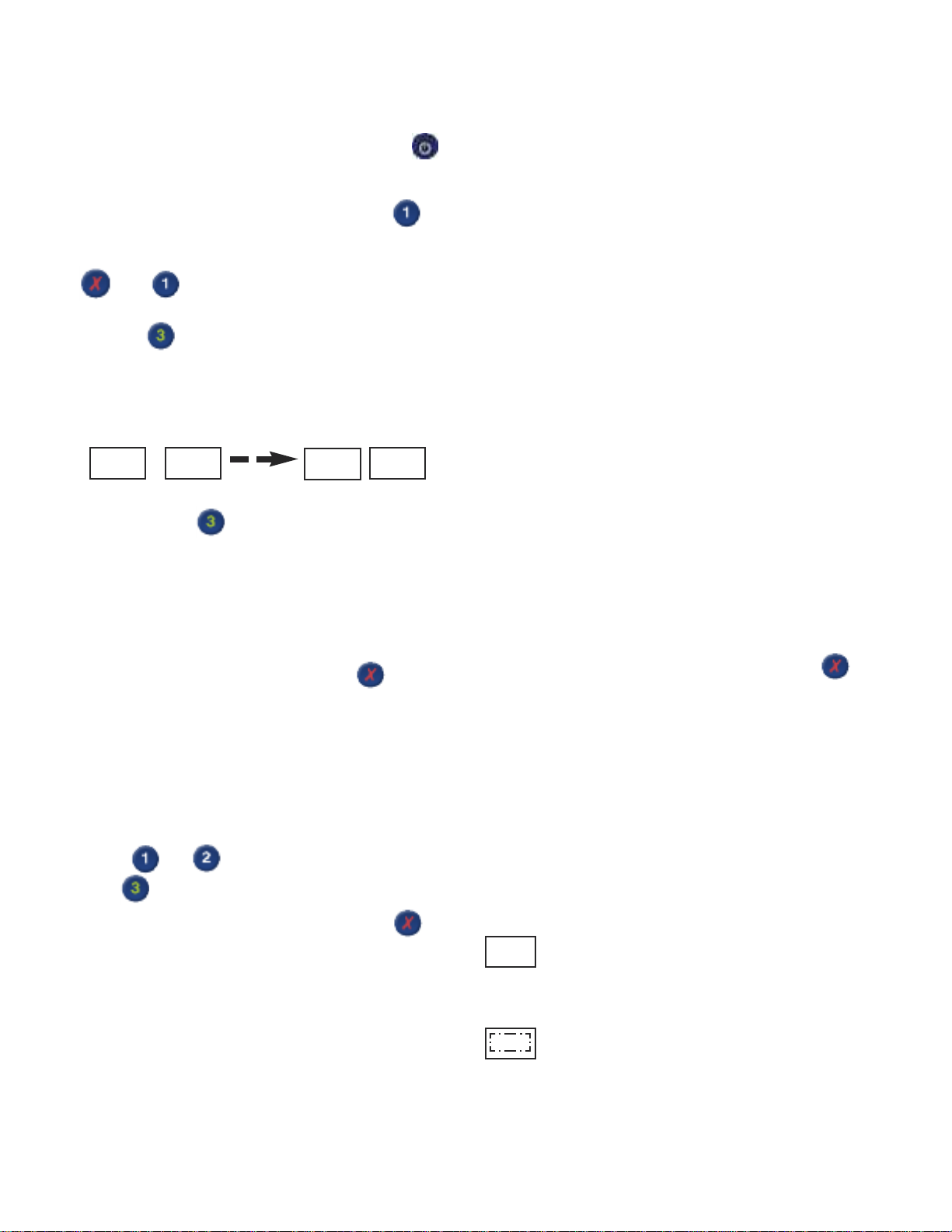
When a Blast Cycle has been initiated - the following will be
displayed:
00
Left Display Window - time counting up
Right Display Window - clockwise rotating LEDS signifying
a cycle in progress
5
Page 6

The blast cycle is ended under normal operation by:
- Reaching the required temperature 37°F (+3°C).
- Reaching the end of the designated time (90 or 240
minutes).
- Manual cancellation of the cycle by pressing and
holding for 2 seconds.
- Putting the controller into standby mode by pressing
A blast cycle may also be terminated due to the following
faults or failures:
- Over temperature fault.
- HP/LP fault (if enabled).
- Air probe (T1) failure.
- Food probe failure - terminates the blast cycle if all the
food probes fail. If a 3 probe system is used, and 1 probe
fails, the cycle will continue until the last working probe
reaches temperature.
- Main power failure longer than 3 minutes.
Blast Control Panel
During a defrost the display windows will indicate the
following:
90
AL
- - -
A manual defrost can be initiated by pressing and holding
both and
During the defrost cycle all fans will stop running. When the
defrost cycle is finished the compressor will run for
approximately 60 seconds before the fans cut in. It is safe to
leave products in the cabinet during the defrost cycle; the air
temperature rises slightly but will not affect the products
stored.
After every defrost there is a short period; about 5 minutes
duringwhicha blast cycle cannot be programmed. This short
interval is to allow defrost water to drain away from the
evaporator. At the end of each cycle, a defrost will
automatically clear any ice from the evaporator ready for the
next cycle.
dF
dF
dF
Following a blast chill cycle
An alarm condition is present
- - - will appear in the left window if power
failure happens during defrost mode for a
duration of 3 minutes or greater
Hard or Soft Blast Chill Cycles:
During the hard blast chill cycle the air temperature inside
the cabinet should go down to approximately 14°F (-10°C).
This is for the timed chilling cycleonly. Hard blast chill cycles
have the potential to go down to 14°F (-10°C)in temperature.
Duringsoft blast chill cycle the air temperaturestays above
32°F (0°C). Soft blast chill cycles have the potential to go
down to 34°F (1°C) in temperature.
DEFROST
Adefrost cycleis automaticat the end of eachblastchillcycle
to clear any ice from the evaporator ready and to prepare for
the next cycle. During storage mode a defrost will be
performed automatically at the factory preset interval of 6
hours. If a blast cycle is cancelled the machine will
automatically initiate a defrost.
ALARMS
When a fault or adverse operational condition arises, an
audible and visual alarm will be initiated:
General alarm in left window / right
window will show mode (storage
AL
- - -
The alarm will sound intermittently. Press to mute the
alarm, the alarm will retrigger if the fault causing the alarm
has not been addressed. The alarm mode will still be
displayed.
More information on the alarm can be displayed during
normal operation by accessing the diagnostic menu by
pressing and holding for 3 seconds.
03
temperature / blast or defrost)
Mains failure alarm in left window /
right window will show mode (storage
dF
temperature / defrost; longer than 3
minutes)
Left window indicates alarm - the
right window indicates the type of
AL
E3
alarm.
6
Page 7

When a probe is at fault then the left window will display
probe type and the right window indicates the fault type.
T1 - air probe
T2 - evaporator probe
T3 - auxiliary probe (not applicable)
T4 - Food probe 1
T5 - Food probe 2
T6 - Food probe 3
AIRFLOW
In the unlikely event that your blast
chiller is taking longer to perform its
chilling cycle, ensure that the system
is operating in the correct way. A
possible explanation is that the fan
system has been installed the wrong
way round. As a result the airflow within the blast chiller will
not work as effectively as it should. See the diagram.
Alarm codes that are displayed are:
E1 - HP/ LP fault (not applicable)
E2 - Over temperature
E3 - Mains failure longer than 3 minutes
Hi - High temperature
Lo - Low temperature
or - probe over range failure
ALARMS DURING BLAST CHILL
CYCLES
If the blast chill cycle has been terminated as a result of a
fault causing an alarm, a defrost cycle will automatically be
initiated. However, it an alarm occurs such as evaporator
probe (T2) fault then the blast chill cycle will continue.
CANCELLING ALARMS
Alarms may be cancelled in the following way:
- Putting the cabinet in standby will cancel all alarms
- All alarms can be reset when the fault is removed,
except the mains failure alarm. This alarm remains
displayed until another blast cycle is initiated.
DOOR OPERATED FAN &
CONDENSING UNIT CUT-OUT
SWITCHES (if fitted)
If the door is opened during blast or store mode the
refrigeration unit and evaporator fans will cut out. Both will
restart on closure of door.
COMPLEMENTARY COMPRESSOR
CONTROL
In addition to the conventional operation of the compressor,
the following complementary function applies;
Compressor Rest Time
This function is to ensure that the main compressor does not
run too frequently, and succumb to damage. The parameter
“crt” can be adjustedaccordingly. The compressor rest time
does not apply to the beginning of a blast cycle or hot gas
defrost cycle.
Compressor Duty Cycle
This function performs the task of overriding the controller’s
logic when an air probe (T1) fails, thus preserving the food
until a service technician performs service work.
The parameter “cdc” controls the number of forced
compressor cycles per hour.
Example: If set to 5, the compressor (compressor used for
store) will alternate, 5 minutes running, 5 minutes off and so
on.
High Pressure / Low Pressure Control
To enable the High Pressure / Low Pressure control, the
parameter “PS” must be set to “YES”. Once set the main
compressorrelay output is additionallycontrolledbythe High
Pressure / Low Pressure switch (terminals L3 and L2 in
series with terminal L1). If the High Pressure / Low Pressure
input goes open circuit, then the main compressor will stop
running and an alarm “E1” will be displayed.
Note: it is not advisable to open the door during blast mode
as this will effect cycle.
NB: If the High Pressure / Low Pressure input goes open
circuit during a hot gas defrost, the alarm is ignored. A
subsequent refrigeration cooling cycle will trigger the alarm if
the input stays open circuit.
If a High Pressure / Low Pressure switch is not fitted then
terminals L2 and L3 have to be linked.
7
Page 8

THERMOSTATS & PROBES
Thermostats
The controller can, via the set of thermostat parameters,
control the refrigerationfor soft blast chill, hard blast chill and
chill store.
All have independent parameters for set points and the two
hysteresis parameters are for chill thermostats.
NB: The soft blastchill thermostat is a “delta” (floating) value
to be added to the store chill thermostat set point to achieve
the final soft blast chill thermostat set point.
Example: If the store chill thermostat is set to 37°F (+3°C)
and the soft chill value is set to 37°F (-2°C), then the
achieved soft blast thermostat will be 28°F (+1°C).
Williams Data Logger & Printer
MISCELLANEOUS FUNCTIONALITY
Condenser Clean
Thecondenserwillrequire cleaningfromtimetotime. Atimer
parameter“Acc”is used to logthe compressor run time (units
of weeks). After the preset period a warning is announced.
Probes
The type of probe sensor used for all probes is of the
KTY-81-121 type.
The controller will always require the air (T1) and evaporator
(T2) probes. The number of food probes is selectable from
0 to 3.
If the number of food probes is set to 1, then only the alarm,
diagnostics and temperature controlled blast cycle will be
respective to probe (T4). All other food probes (T5 and T6)
will be ignored. The auxiliary probes (T3) function can be
selected via the parameter “3PM” (default to “no”).
NB: If any probe is enabled but not connected, a probe
failure will arise.
All probes have an offset parameter to compensate for
temperature driftandmanufacturing tolerancesof the probes.
WILLIAMS DATA LOGGER & THERMAL
PRINTER
The Williams Data Logger is connected to a thermal printer
which requires a 2.24” (57mm) with a diameter not greater
than 1.57” (40mm) thermal printer paper roll.
Forthe purposeof notifyingtheuser, a designatedcondenser
clean button and LED are used. Aflashing red LED signifies
that the condenser requires cleaning.
Pressing and holding the button for 3 seconds will reset the
timer and the LED will stop flashing.
Display Slow Down
The purpose of applying a “display slow down” is to delay the
real time temperature being displayed on the controllers front
control interface. This will avoid rapid fluctuations displayed
when a door is opened, or when the controller is “hunting”
the instantaneous temperature.
This is achieved by introducing a thermal mass simulation
routine in the software to stimulate a thermal mass inside the
chiller. The parameter “SiM” (default to 3) is used, and an
example being a value of 100 simulates a 0.5 litre (0.1
Gallon) bottle of water.
The Data Logger retains approximately 7 days worth of data
(depending on usage) by default. This includes all blast
cyclesthathave been completedor cancelled,defrosts,store
cycles and all alarms. All of the stored data is printed by
pressing and holding the button next to ‘Print’ (1) for 3
seconds. Aconfirmation message‘Printing’will be displayed.
Please see Page 12 for additional functions and features.
8
Page 9

MAINTENANCE
The cabinets are fully automatic in operation. Cleaning and
loading thermal paper is the only maintenance required.
Read the following topics.
Exterior Cleaning
The exterior of the cabinet is stainless steel and if cared for
correctly will keep is ‘as new’ finish for many years. Normal
day to day cleaning should be carried out with a soft cloth
and soapy water. Always wipe the cabinet vertically in the
same direction as the grain in the stainless steel. While
stainless steel is a very strong and robust material, the
smooth finish can be spoiled by wiping against the grain.
Never use abrasive materials or cleaners, or chemical
cleaners, as they can damage the surface and cause
corrosion. Occasionally,the exterior should be polished with
a good stainless steel polish to protect the surface.
Do not use abrasive cleaners, chemicals or scouring pads
on the control panel. Clean the control panel only with a soft
damp cloth. Avoid excess water on the control panel, and
other areas where electrical components are fitted.
Interior Cleaning
The racking can be removed for easy cleaning (see Figure
2). This should be done on a regular basis with warm water
and a soft cloth, dry thoroughly afterwards. To remove the
racking and shelf supports follow this procedure:
First remove shelves, then supports by gripping firmly at the
center and lifting slightly. Turn shelf support towards cabinet
interior by pushing at the center as you twist support through
90°. The shelf support will be released. (Note: the supports
are designed to be anti-tilt and some resistance may be
experienced at first. This will be overcome with practice).
When all shelves have been removed, remove the racking
by lifting up and over the nylon retaining blocks.
Door Gasket
Cleanthe gasketweeklywith warm soapy
water and a soft cloth taking care not to
damage it. DO NOT use a sharp knife to
clean or scrape the gasket. Regularly
check the gasket for any damage.
Damage can be caused by striking the
gasket with a sharp object such as the corner of a tray.
Damaged gaskets do not seal correctly and can increase the
amount of electricity consumed, seriously affecting the
efficiency and performance of the cabinet.
Damaged gaskets are easily replaced. To fit a new gasket simply pull out the old gasket and push the new gasket into
the channel (gasket retainer) at the center and work along
the gasket pushing it into the channel, continue in the same
way on the other three sides, pushing the corners in last.
Condenser Cleaning
The condenser, which is part of the refrigeration unit, is
located in the unit compartment and requires cleaning
approximately 4 times per year or when the LED indicates.
To clean the condenser, disconnect main power supply
before starting, then brush the fins vertically with a stiff
brush (taking care not to damage the fins or push dirt / dust
further into the condenser coil) and vacuum the dirt / dust
away. Remember to reconnect main power supply when
finished.
TECHNICAL SERVICE &
REPLACEMENT PARTS
Beverage-Air strives to provide excellent customer service
along with quality equipment. To help us better assist you, a
serialnumber and / or model numbermust be provided when
contacting the technical service or parts department. The
data plate is located inside the reach-in cabinet on the right
side wall. Roll-in blast chiller data plates are placed on the
exterior of the back panel that supports the controller. All
serial numbers are recorded and kept indefinitely.
9
Page 10

RULES OF THUMB
1. Pre-chill thecabinetfor30 minutesbeforeyoudo first load
(this is to remove interior residual heat).
2. Doubling the food thickness triples the pull-down time.
3. Don’tstack food and / or containers on top or alongside or
each other.
4. Covering the food increases pull-down time by 10% 30%.
5. Pull-down rate initially is about 2°F per minute and
approaching final temperature is about 2 minutes per
degree Fahrenheit.
6. Factors affecting blast chiller pull-down times:
- Entering food temperature (the hotter the initial
temperature, the longer the pull-down time).
- Final food temperature (the colder the final
temperature, the longer the pull-down time).
- Food “thickness” (the greater the distance from
geometric“core”centerof food to its surface pull-down
time).
- Food density (the greater the density, the longer the
pull-down time).
- Food thermal conductivity (the lower the conductivity,
the longer the pull-down time).
- Food specific heats (the higher the specific heat, the
longer the pull-down time).
- Container surface area (the smaller the surface area,
the longer the pull-down time).
- Container material (metals are conductors and render
a shorter pull-down time than plastics which are
insulators).
- Covering material (metal preferred instead of plastic
for reasons above).
- Covering method-cover such as aluminium foil or a
“stretch wrap film” placed in direct contact with food
eliminatesthe “dead air space” between the cover and
the food. Since “dead air space” is an insulator,
elimination of reduction of it shortens pull-down time.
- “Delta T” is temperature difference between the food
and the blast of air. The greater the “Delta T” the
quicker the pull-down time.
- Air velocity (the greater the air velocity across the food,
the faster the pull-down time).
- Amount (weight) of food put in as compared to rated
capacity machine. Exceeding the capacity increases
the pull-down time.
10
Page 11
BEFORE CALLING SERVICE GUIDE FOR WBC COMMON PROBLEMS
CAUTION: Disconnect power supply prior to attempting any service!
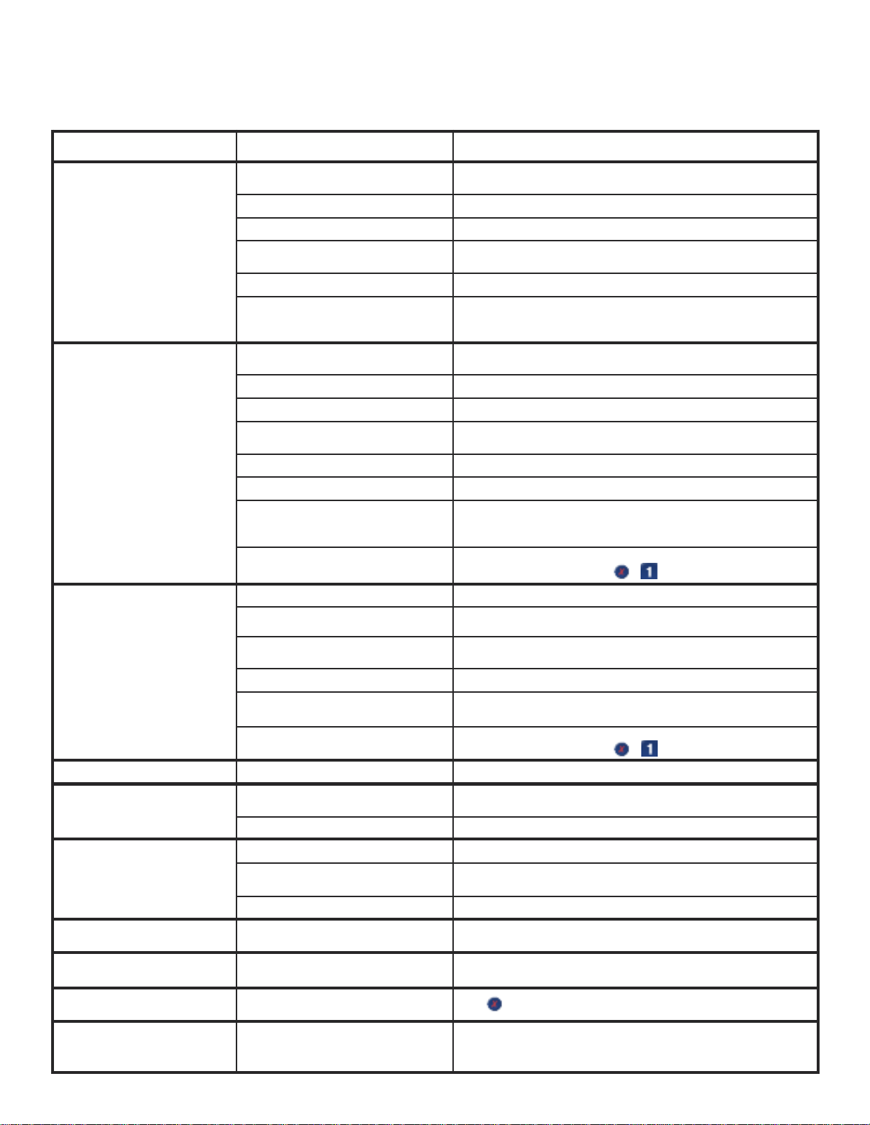
Problem Possible Cause Remedy
Cabinet not running and / or no
1-2-3 controller display
Circuit breaker tripped
Power cord unplugged Plug in power cord
Main power supply turned “OFF” Turn main power supply “ON”
Improper voltage supplied to cabinet
Cabinet in defrost cycle Allow defrost cycle to finish
Reset circuit breaker (make sure circuit breakers show red indicators
for “ON” position)
Supply correct voltage (do not use extension cords or put other
equipment on circuit etc)
Cabinet not pre-chilled prior to placing hot
product load
Excessive amount of warm product
Condensing unit on cabinet runs
for prolonged period or
continuously
Cabinet temperature too high
Cabinet is noisy
Product taking to long to pull-down
Compressor will not start hums
and trips circuit breaker
Door won’t close tight Cabinet is not level
Water or ice at bottom of cabinet Product load too hot
Error code displayed
Thermal printer paper not
feeding or printing tickets
loaded in cabinet
Whole product loads placed in cabinet Portion product load(s)
Improper use of “Soft Chill” mode Use “Soft Chill” for delicate and less dense product loads only
Prolonged door opening or door ajar
Door gasket not sealing properly Check gasket condition. Adjust door or replace gasket
Dirty condenser coil Clean the condenser coil
Improper air flow around condensing unit
Evaporator coil blocked with ice
Poor air circulation in cabinet Move product load away from fan(s)
Excessive amount of warm product
loaded in cabinet
Prolonged door openings or door(s) ajar
Dirty condenser coil Clean the condenser coil
Insufficient clearance around cabinet or
excessively high ambient temperature
Evaporator coil blocked with ice
Part(s) loose Locate and tighten loose part(s)
Product load covered
Improper use of “Soft Chill” mode Use “Hard Chill” for product loads that are of great density
Dirty condenser coil Clean the condenser coil
Excessive heat generated from
equipment nearby
Voltage to cabinet too high or too low Checkand correct supply voltage
Loose or defective food probe /
thermocouple. Main power failure
Thermal printer paper jamming, not
straight or properly seated. Printer paper
spool is finished
Remove product load and pre-chill cabinet for approximately 30
minutes (only applies to cabinets that do not stay on all the time)
Allow adequate time for product to cool down
Make sure door is closed when not in use. Avoid prolonged door
openings
Ensure adequate air space, relocate away from heat generating
equipment, direct sunlight, or direct path of air conditioning or heating
ducts
Turn unit off and allow coil to defrost or manually force defrost (while
cabinet is “ON”, press and hold & button for manual defrost)
Allow adequate time for product to cool down
Make sure door(s) are closed when not in use. Avoid prolonged door
openings
Ensure adequate air space, relocate away from heat generating
equipment (ovens, fryers etc) and out of direct sunlight
Turn unit off and allow coil to defrost or manually force defrost (while
cabinet is “ON”, press and hold & button for manual defrost)
Uncover product or try to use metal pans. Refer to Page 3 or “The
Guide to Cook Chill”
Relocate cabinet, or adjacent heat generating equipment
Level cabinet by adjusting casters or legs. Shim casters or legs if
necessary
Cool down product load before placing into cabinet (Note: product load
should be no higher than 160°F)
Press (cancel) button to stop alarm sound off
Reload paper
11
Page 12
by
OPERATING / ENGINEERS MANUAL for
WILLIAMS DATA LOGGER (W.D.L) with PRINTER MODULE
12
Page 13

2.0 SPECIFICATION
2.1 POWER SUPPLY
The Williams Data Logger (W.D.L) is supplied with a 12VDC
from a Switch-mode power supply (S.M.P.S).
2.2 PRINTER PAPER ROLL
The W.D.Lis connected to a thermal printer which requires a
(57mm / 2.24” with a diameter not greater than 40mm)
thermal printer paper roll.
2.3 I.P (INGRESS PROTECTION) RATING
The W.D.L and printer module are protected by a
polycarbonite hinged cover that has an IP rating of 65 when
in the closed position.
2.4 HARDWAREAMBIENT OPERATING LIMITS
The printer and W.D.L are guaranteed to operate in an
ambienttemperature between -10°C / 14°F and 50°C / 122°F
in a 15 to 80% of relative humidity.
3.0 OPERATION OVERVIEW
3.1 DISPLAYS DURING CABINET OPERATION
When an operation cycle (e.g.- timed blast) has been
initiated, the W.D.L will display information relevant to that
cycle (as shown below).
3.1.1 Timed and Temperature Based Blast Cycle
The screens shown below will be displayed during a timed
blast and temperature based blast cycle. The W.D.Lcan still
be used during operation (e.g.- parameterscan be accessed,
stored data can be viewed etc.).
3 secs
3.2 DATA RECORDING MODE
The W.D.L is used to record the controllers status and the
temperature measured by the selected probe (through a
parameter) every 5 seconds.
3.2.1 Alarms
If an alarm occurs, the time, date, controller status and
temperature are recorded into the W.D.L’s memory and
printed immediately on a ticket.
- Power Failure = PWF
- High Temperature = HI_T
- All Other Alarms = ALM
3.2.2 Blast Mode (Time)
The time, date and temperature of the Air probe at the
beginning and the end of the blast cycle are recorded.
3.2.3 Blast Mode (Temperature)
The threshold duration is recorded, i.e. the time taken for the
food probe temperature to reach the setpoint from the
highest recorded temperature.
If a blast cycle is not active, the average hourly temperature
and any alarms are stored while the recording is taken.
3.3 DATA STORAGE
Data recorded is stored on the W.D.L automatically and can
be printed at anytime manually.
3 secs
3.1.2 Defrost
The screen shown below is displayed during a defrost cycle.
The W.D.L can still be used during operation (e.g.parameters can be accessed, stored data can be viewed
etc.).
3 secs
3.4 DISPLAY MODE INDICATIONS
The current cabinet status will be displayed in the top
right-hand corner of the default display screen during
operation.
3.4.1 Standby
When the W.D.Lis in standby, ‘- - -’ will be displayed.
3.4.2 Temperature Logging
The current internal cabinet temperature (e.g. ‘39°F / 4°C’)
will be displayed.
3.4.3 Defrost
A defrost or recovery period is indicated by ‘dF’ being
displayed (see section 3.1.2 for more details).
13
Page 14

3.4.4 Communication Error
In the event of a communicationerror, ‘Err’ is displayed. See
section 3.6 for more details should this occur.
1
3
2
4
3.5 RESOLVING A COMMUNICATION ERROR
In the event of a communication error, ‘Err’ is displayed on
the top right of the W.D.L. If this should happen, check that
the data cable is not damaged and is connected properly
and, that the assigned cabinet address parameters on the
Williams Easy Blast (W.E.B) (parameter “nr”) controller and
W.D.L (parameter “Cab.ADR”) are the same (see section
4.6.4).
3.6 BACKLIGHT AND DISPLAY
The backlight will remain on permanently (even when in
Standby mode). The contrast of the display can be adjusted
using the W.D.L’s parameters (see section 4.5.4 for more
details).
4.0 DISPLAY SCREENS AND BUTTON
OPERATION
4.1 SWITCHING ON THE W.D.LAND PRINTER
The data logger and printer will be switched on from Standby
mode automatically when the main controller is switched on
from Standby mode. For approximately 3 seconds after
switchingon the cabinet, ‘- - -’ will be displayed, this indicates
a standard internal self-test phase before the controller is
ready for use.
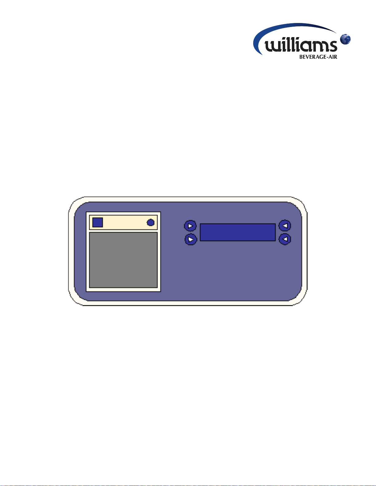
4.2 DEFAULT DISPLAY SCREEN
The default display screen will show the company name and
dateon the left-hand side, the current cabinet status and time
are displayed on theright-handside as shownin the diagram
directly below. The W.D.L will revert back to the default
display automatically after 30 seconds.
1
3
2
4
4.3.1 Printing Stored Data
The W.D.L retains approximately 7 days worth of data
(depending on usage) be default. This includes all blast
cyclesthathave been completedor cancelled,defrosts,store
cycles and all alarms. All of the stored data is printed by
pressing and holding the button next to ‘Print’ (1) for 3
seconds. A confirmation message ‘Printing’ will be
displayed.
4.3.2 Viewing Stored Data
The stored data can be viewed by pressing the ‘View’ (2)
button. In someinstances (such as when viewing blast cycle
or power failure alarm information) further information is
available relevant to the cycle / alarm (as shown below).
4.3.2.1 Blast Cycle Extended Information
View the stored data by pressing the ‘View’ (2) button (as shown
below).
1
3
By pressing and holding the ‘V’ (4) button, it is possible to view the
extended information relevant to the cycle (as shown below).
1
3
By pressingandholding the‘V’(4) button for 3 seconds or more,the
start temperature and duration for each enabled food probe will be
displayed. The display will automatically cycle to the next food
probe after 3 seconds (as shown below).
2
4
2
4
Access the Main Menu (refer to diagram below) by pressing
any button.
4.3 MAIN MENU SCREEN
The main menu screen allows you to select a number of
parameters and operations. See below for more details and
a diagram of the menu layout.
14
3 secs
3 secs
3 secs
Page 15

The display will exit the advanced information as soon as the ‘V’ (4)
button is released.
1
2
4.3.2.2 Power Failure Alarm Extended Information
View the stored data by pressing the ‘V’ (4) button (as shown
below).
1
3
By pressing and holding the ‘V’ (4) button, you are able to see
exactly when the power failure occurred and when the power
supply was re-established (as shown below).
1
3
2
4
2
4
4.4 MAIN SETUP MENU
The main setup menu (as shown in the diagram below) can
be accessed by pressing the ‘Settings’ (4) button ont he
main menu (see section 4.3 diagram for more details).
3
4
Use the ‘+’ (2) and ‘-’ (1) buttons to increase and decrease
the value. When you are happy with your selection. Press
the ‘Ok’ (4) button to save and exit. Alternatively, press the
‘<<’ (3) to cancel and exit.
4.5 ADVANCED SETUP MENU
The advanced setup menu can be accessed by pressing the
‘Setup’ (1) button at the main setup menu (see section 4.4).
The diagram below depicts the screen that will be displayed.
Use the ‘ ‘ (2) and ‘ ‘ (1) buttons to scroll forwards
and backwards between Tect, Date Format, Summertime,
Contrast and Passcode. Adjust the selected Text, Date
Format, Summertime etc by pressing the ‘Set’ (4) button
whilst the desired parameter is displayed. It will now be
possible to adjust the selection (as shown below).
1
3
2
4
1
3
2
4
4.4.1 Clearing Stored Data
It is possible to clear the stored data by pressing and holding
‘Rst Data’ (4) for 3 seconds. The confirmation message
‘Data Deleted’ will be displayed to show that the data
deletion has been successful.
4.4.2 Setting the Time and Date
The time and date setup menu can be accessed by pressing
the ‘Time’ (2) button. The screen shown below will be
displayed.
1
3
2
4
Use the ‘ ‘ (2) and ‘ ‘ (1) buttons to scroll forwards
and backwards between Hour,Minute, Day.Month and Year.
Adjust the selected Hour, Minute, Day etc by pressing the
‘Set’ (4) button whilst the desired parameter is displayed. It
will now be possible to adjust thevalue (see example below).
4.5.1 Language Selection
Upon entering the advanced setup menu, the language
selection option will be displayed immediately (as shown in
4.5). Press the ‘Set’ (4) button to access the language
selection(asshown below). Use the ‘+’ (2) and ‘-’ (1) buttons
to scroll forwards and backwards through the available
languages. When you are happy with your selection, press
the ‘Ok’ (4) button to save and exit. Alternatively, press the
‘<<’ (3) to cancel and exit.
1
3
2
4
The W.D.L can be selected to operate in the following
languages:
- English
- Deutsch (German)
- Espanol (Spanish)
- Francais (French)
15
Page 16

4.5.2 Date Format Selection
The date format can be changed to suit European or
American layout formats. Whilst in the Advanced Setup
Menu (see section 4.5), scroll to the ‘DateFormat’
parameter by using the ‘ ‘ (2) and ‘ ‘ (1) buttons and
press the ‘Set’ (4) button to adjust the selection. The screen
shown below will be displayed.
1
3
The W.D.L can be selected to operate in the following date
formats:
- DD/MM/YY
- MM/DD/YY
2
4
The contrast can be set between 0 and 50. The greater the
value, the more ‘clouded’ the display will appear. Use the ‘+’
(2) and ‘-’ (1) buttons to increase / decrease the value.
4.6 ENGINEERING PARAMETERS
The engineering parameters are used to control much of the
W.D.L’s temperature logging and other advanced
functionalities. Should these parameters require
modification, it should only be undertaken by an engineer as
the behaviour of the W.D.Lcan be greatly affected.
Whilst in the Advanced Setup Menu (see section 4.5), scroll
to the ‘Pass Code’ parameter by using the ‘ ‘ (2) and
‘ ‘ (1) buttons and pressthe ‘Set’ (4) button. Apass code
will be required to access the engineering parameters (as
shown below).
1
2
Use the ‘+’ (2) and ‘-’ (1) buttons to scroll through the
available selections.
4.5.3 Summertime Enabling / Disabling
The ‘Summertime’ mode is used for daylight savings. Whilst
in the Advanced Setup Menu (see section 4.5), scroll to the
‘Summertime’ parameter by using the ‘ ‘ (2) and ‘ ‘
(1) buttons and press the ‘Set’ (4) button to adjust the
selection (as shown below).
1
3
The W.D.Lcan be set to daylight savings enabled / disabled
as follows:
- On (+1 hour to the set time)
- Off (Time remains unadjusted)
Use the ‘+’ (2) and ‘-’ (1) buttons to scroll through the
available selections.
4.5.4 Setting the Display Contrast
The contrast can be adjusted to make the screen more / less
visible. Whilst in the Advanced Setup Menu (see section
4.5), scroll to the ‘Contrast’ parameter by using the ‘ ‘
(2) and ‘ ‘ (1) buttons and press the ‘Set’ (4) button to
adjust the selection (as shown below).
2
4
3
The pass code to enter the engineering parameters is ‘127’.
Use the ‘+’ (2) and ‘-’ (1) buttons to increase and decrease
the value and press ‘Ok’ (4) to confirm the selection.
The screen shown below will be displayedto confirm that you
have successfully entered the pass code and are now in the
engineering parameters.
1
3
Use the ‘ ‘ (2) and ‘ ‘ (1) buttons to scroll forwards
and backwards between the avilable parameters (see page
17 for more details).
4.6.1 Setting the Company Name (Parameter ‘Company
name’)
The company name can be adjusted accordingly to change
the company name that will be displayed in the top left-hand
of the Defauly Displayscreen(seesection4.2for examplediagram). Whilst in the engineering parameters (see section
4.6 for eaxmple diagram), scroll to the ‘Company name’
parameter by using the ‘ ‘ (2) and ‘ ‘ (1) buttons and
press the ‘Set’ (4) button to edit the selection (as shown
below).
4
2
4
1
1
3
2
3
4
Use the ‘+’ (2) and ‘-’ (1) buttons to scroll through the
available selections.
2
4
16
Page 17

Parameter Section Number Min. Value Max. Value
Company Name 4.6.1 Williams Blank
ReadProbe 4.6.2 Air Food3
ADR 4.6.3 00 255
Cab.ADR 4.6.4 00 255
Rec.Mode 4.6.5 Normal FDA
BlastCycle 4.6.6 Normal NonStop
Print blast 4.6.7 Yes No
Store cycle 4.6.8 1 168
4.6.3 Setting the Cabinet Device Address (Parameter
‘Cab.ADR’)
The cabinet device address is to be set to the same value on
both the W.E.B controller and the W.D.L to enable
communication between them. Parameter ‘nr’ of the W.E.B
controller (see W.E.B controller engineer’s manual for more
details)is to havethe same value as parameter ‘Cab.ADR’of
the W.D.L. Scroll to the ‘Cab.ADR’ parameter by using the
‘ ‘ (2) and ‘ ‘ (1) buttons and press the ‘Set’ (4)
button to edit the selection (as shown below).
1
3
2
4
ChillHigh 4.6.6 and 4.6.9 20 212
Chill Low 4.6.6 and 4.6.10 -20 70
Freeze high 4.6.6 and 4.6.11 00 212
Freeze low 4.6.6 and 4.6.12 -40 30
FDA1H 4.6.6 and 4.6.13 00 212
FDA1L 4.6.6 and 4.6.14 -40 70
FDA2H 4.6.6 and 4.6.15 00 212
FDA2L 4.6.6 and 4.6.16 -40 70
4.6.2 Setting the Sample Probe
(Parameter ‘ReadProbe’)
The sample probe (Read probe) is the probe that is sampled
to display the temperature at the top right-hand corner of the
defaulydisplay screen(seesection 4.2 for examplediagram).
Scroll to the ‘ReadProbe’ parameter by using the ‘ ‘ (2)
and ‘ ‘ (1) buttons and press the ‘Set’ (4) button to
edit the selection (as shown below).
1
2
The W.D.Laddress can be adjusted from 0 to 255. Use the
‘+’ (2) and ‘-’ (1) buttons to increase and decrease the value.
4.6.4 Setting the Recording Mode (Parameter Rec.Mode)
The recording mode dictates in the way in which the W.D.L
will store and print data. Scroll to the ‘Rec.Mode’
parameter by using the ‘ ‘ (2) and ‘ ‘ (1) buttons and
press the ‘Set’ (4) button to edit the selection (as shown
below).
1
3
2
4
The recording mode can be selected as follows:
4.6.4.1 Normal
The probe blast cycle start and end temperature for each enabled
food probe and duration will be stored and printed. If the cycle is
cancelled, the highest and lowest reached temperatures for each
enabled food probe and duration upon cancelling the cycle are
recorded.
3
4
The read probe can be selected as follows:
- Air Measures cabinet air temperature (default probe).
- Evp Measures evaporator temperature.
- Aux Auxiliary probe (optional and often used for
additional fuctionality).
- Food1Measures the temperature of food probe 1.
- Food2Measures the temperature of food probe 2 (if fitted).
- Food3Measures the temperature of food probe 3 (if fitted).
Use the ‘+’ (2) and ‘-’ (1) buttons to scroll through the
available selections.
4.6.4.2 French
If a soft or hard blast chill cycle is selected, the time take for each
food probe to pull down the temperature assigned to parameter
‘ChillHigh’ to ‘ChillLow’ is stored and printed.
If a blast freeze cycle is selected,thetimetakenforeachfoodprobe
to pull down from the temperature assigned to parameter ‘Freeze
high’ to ‘Freeze low’ is stored and printed.
If a blst cycle terminates without reaching the temperature limits,
the duration is not stored and is replaced by ‘??’ when the
information is printed.
17
Page 18

4.6.4.3 FDA
Twotimedurations will be stored and printed for each enabled food
probe. The first will be the time taken to pull down from parameter
‘FDA1H’ to ‘FDA1L’,and the second is the time taken to pull down
from ‘FDA2H’ to ‘FDA2L’.
If a blast cycle terminates without reaching the temperature limits,
the duration is not stored and is replaced by ‘??’ when the
information is printed.
Use the ‘+’ (2) and ‘-’ (1) buttons to scroll through the
available selections.
4.6.5 Enabling / Disabling Auto. Print After A Blast
Cycle (Parameter ‘PrintBlast’)
It is possible to enable / disable the auto print after a blast
cycle by scrolling to the ‘Print blast’ parameter by using the
‘ ‘ (2) and ‘ ‘ (1) buttons and pressing the ‘Set’ (4)
button to edit the selection (as shown below).
1
3
2
4
The auto print after a blast cycle mode can be selected as
follows:
- Yes A ticket will be printed automatically after a blast
cycle or when a probe achieves its temperature
setpoint.
4.6.7 First Temperature Setpoint Used in French Blast
Chill Mode (Parameter ‘ChillHigh’)
See section 4.6.5. The parameter can be set between 20
and 212.
4.6.8 Second Temperature Setpoint Used in French
Blast Chill Mode (Parameter ‘ChillLow’)
See section 4.6.5. The parameter can be set between -20
and 70.
4.6.9 First Temperature Setpoint Used in French Blast
Freeze Mode (Parameter ‘FreezeHigh’)
See section 4.6.5. The parameter can be set between 0 and
212.
4.6.10 Second Temperature Setpoint Used in French
Blast Freeze Mode (Parameter ‘FreezeLow’)
See section 4.6.5. The parameter can be set between -40
and 30.
4.6.11 First Temperature Threshold Value 1 Used in
FDA Blast Mode (Parameter ‘FDA1H’)
See section 4.6.5. The parameter can be set between 20
and 212.
4.6.12 Second Temperature Threshold Value 1 Used in
FDA Blast Mode (Parameter ‘FDA1L’)
See section 4.6.5. The parameter can be set between -40
and 70.
- No A ticket will not be printed automatically after a blast
cycle or when a probe achieves its temperature
setpoint.
4.6.6 Setting the Number of Hours of Data to be Stored
(Parameter ‘Store cycle’)
The number of hours worth of data to be stored can be
altered by adjusting parameter ‘Store cycle’. Scroll to the
the‘Storecycle’parameter by using the ‘ ‘ (2) and ‘ ‘
(1) buttons and pressing the ‘Set’ (4) button to edit the
selection (as shown in the diagram below).
1
3
2
4
The number of hours worth of stored data to be retained can
be adjusted between 1 and 168. Use the ‘+’ (2) and ‘-’ (1)
buttons to increase and decrease the value.
4.6.13 First Temperature Threshold Value 2 Used in
FDA Blast Mode (Parameter ‘FDA2H’)
See section 4.6.5. The parameter can be set between 20
and 212.
4.6.14 Second Temperature Threshold Value 2 Used in
FDA Blast Mode (Parameter ‘FDA2L’)
See section 4.6.5. The parameter can be set between -40
and 70.
18
Page 19

by
PARTS LISTS, WIRING DIAGRAMS and CONTROLLER SET-UP
for REACH-IN and ROLL-IN BLAST CHILLERS
19
Page 20

PARTS LIST FOR A WBC35
20
Page 21

PARTS LIST FOR A WBC60
21
Page 22

PARTS LIST FOR A WBC75
22
Page 23

PARTS LIST FOR A WBC110
23
Page 24

PARTS LIST FOR A WMBC175/220/350 CONTROLLER WITH POD & PRINTER
24
Page 25

PARTS LIST FOR A WMBC175/220/350 PANEL LAYOUT
25
Page 26

PARTS LIST FOR A WMBC175/220/350 EQUIPMENT
26
Page 27

PARTS LIST FOR A WMBC175/220/350 POD EQUIPMENT
27
Page 28

PARTS LIST FOR A WMBC175/220/350 PANEL LAYOUT
28
Page 29

PARTS LIST FOR A WMBC350 EQUIPMENT
29
Page 30

PARTS LIST FOR A WMBC480/660 - PANEL LAYOUT
30
Page 31

PARTS LIST FOR A WMBC480/660 - CONTROL PANEL WITH PRINTER & POD
31
Page 32

PARTS LIST FOR A WMBC480 - EQUIPMENT LAYOUT
32
Page 33

PARTS LIST FOR A WMBC660 - EQUIPMENT LAYOUT
33
Page 34

PARTS LIST FOR A WMBC480/660 - POD EQUIPMENT
34
Page 35

PARTS LIST FOR A WMBC480/660 - PANEL LAYOUT
35
Page 36

115
240
208
MAINSSELECTION
TEMP
OVER
E18
-B1
-B2
-B3
-B4
-B5
-B6
T1
AIR
T2
T3
T4
T5
T6
EVP AUX FP1 FP2 FP3
REMOTE
DATAI/O
L10 L11
L N
SWITCH
DOOR
Whi
Red
Whi
Red
Whi
Red
Whi
Red
Whi
Red
Whi
Red
Linkforrequiredvoltage
-B7
HP/LP
STAT
L2 L3
-W1
10Amp
-Q1
1
2
3
4
5
6
-K1
-W3
-W4
-P2
-P1
2.5mm(13AWG)
M M
-E1
-W2
(1) (2)(G/Y) (2)(1)
-X1 -X1
6Amp
-Q2
G
1 2
L1 L2
5 6
7
8
(KEYON PAGE2)
7 83
4
G
2.5mm
2.5mm
2.5mm
WIRING DIAGRAM FOR A WBC35
36
Page 37

Key
-B7
-B8
KTY-81-121 RTDPROBES-B1-B6
115
240
208
MAINSSELECTION
TEMP
OVER
E18
T1
AIR
T2
T3
T4
T5
T6
EVP AUX FP1 FP2 FP3
REMOTE
DATAI/O
L10 L11
L N
SWITCH
DOOR
Linkforrequiredvoltage
2.5mm(13AWG)
UNLESSSTATEDOTHERWISE
-ALL CABLESARETRI RATED
-PRINTEROPTION SEEdiag1026
WIRECOLOURS: Blu :BLUE
Brn: BROWN
G/Y: GREEN/YELLOW
Blk: BLACK
Whi: WHITE
Red: RED
L1 L2G
10Amp
-Q1
1
2
3
4
5
6
-K1
M
M
-E1
1.5mm(16AWG)
1 2
-P1
6Amp
-Q2
1.5mm(16AWG)
-W3
-B7
5 6
8
7
NOTES: - ALLCABLESARE1.Omm (17AWG)BLACK
OVERTEMPBI-METALSWITCH (194°F)
HPSWITCH
-MAINS SUPPLY CONNECTIONS USE
COPPERCONDUCTORS ONLY
-W2
(1) (2)
(G/Y)
-X1
G
1.5mm(16AWG)
1.5mm(16AWG)
3
4
(1)(2)
-W4
7 8
-X1
-B9
CONDENSOR UNIT
-E3
-E2
-E1
-E4
VAPTRAYHEATER
DEFROSTHEATERS
-F1 DEFROSTKLIXON
DOORHEATER
4kWCONTACTOR
-K1
-W1
-W2
-W3
-W4
-W5
-W6
-W7
-W8
-W9
FRONTCONTROLPCBINTERFACE
REARMAINPCB (INPUT/ OUTPUT)
-Q2
-Q1
-P2
-P1
4-CORE1.0mm(17AWG) CSACABLE
2.5mm(13AWG)3COREPVC CABLE(MAINSLEAD)
3-CORE1.5mm(16AWG) CSACABLE
2-CORE1.0mm(17AWG) CSACABLE
10WAYINTERCONNECTINGRIBBON CABLE
3-CORE1.0mm(17AWG) CSACABLE
3-CORE1.0mm(17AWG) CSACABLE
2-POLE6AMPTYPE-C MCB
2-POLE10AMPTYPE-C MCB
-M1
-M2
LPSWITCH
EVAPORATOR BLASTFANS
EVAPORATOR STOREFANS
-W10
-W11
3-CORE1.0mm(17AWG) CSACABLE
3-CORE1.0mm(17AWG) CSACABLE
3-CORE1.0mm(17AWG) CSACABLE
2-CORE1.0mm(17AWG) CSACABLE
RAILMOUNTEDTERMINALS-X1
-W12
3-CORE1.0mm(17AWG) CSACABLE
Whi
Red
Whi
Red
Red
Whi
Whi
Red
Whi
Red
Whi
Red
-B1
-B2
-B3
-B4
-B5
-B6
-P2
WIRING DIAGRAM FOR A WBC60
37
Page 38

(KEYON PAGE1)
L5
M
Blu
G/Y
Blk
Brn
-M1
M
Blu
G/Y
Blk
Brn
-M2
M
Blu
G/Y
Blk
Brn
-M3
L7
-C1 -C2
-C3
(Blu)
(Brn)
(Blk)
(G/Y)
(Blu)
(Brn)
(Blk)
(G/Y)
(Blu)
(Brn)
(Blk)
(G/Y)
(Blu)
(Brn)
(Blk)
(G/Y)
G G
G
-C4
-P2
-X1
G
M
Blu
G/Y
Blk
Brn
-M4
17 17 18 18
17 18
C1
15
C2
15
C3 15
C4
15
WIRING DIAGRAM FOR A WBC75
38
Page 39

Key
WIRECOLOURS: Blu :BLUE
Brn: BROWN
G/Y: GREEN/YELLOW
Blk: BLACK
Whi: WHITE
Red: RED
-ALL CABLESARETRI RATED
NOTES: - ALLCABLESARE1.Omm (17AWG)BLACK
UNLESSSTATEDOTHERWISE
-PRINTEROPTION SEEdiag1026
M M
-E1
16Amp
-Q1
321
1
2
3
4
5
6
-K1
(1)(2)
4 5 6 G
-X1
Linkforrequiredvoltage
115
240
208
MAINSSELECTION
TEMP
OVER
E18
T1
AIR
T2
T3
T4
T5
T6
EVP AUX FP1 FP2 FP3
REMOTE
DATAI/O
L10 L11
L N
SWITCH
DOOR
10Amp
-Q2
7 8
-P1
-P2
9 10
-X1
2.5mm(13AWG)
2.5mm(13AWG)
2.5mm(13AWG)
2.5mm(13AWG)
2.5mm(13AWG)
2.5mm(13AWG)
(G/Y)
(3)
(1)(2)
-W1
-W2
-W3
G
L1
L2
L3
(12AWG)
4.0mm
-MAINS SUPPLY CONNECTIONS USE
COPPERCONDUCTORS ONLY
9
10
2x2.5mm(13AWG)
-E1
VAPTRAYHEATER
-C1-C4 1.5uFCAPACITOR
-E2-E4
-E5
CONDENSING UNIT
DEFROSTHEATERS
DOORHEATER
DEFROSTKLIXON-F1
-K1 7.5kWCONTACTOR
REARMAINPCB (INPUT/ OUTPUT)
2-POLE10AMPTYPE-C MCB
3-POLE16AMPTYPE-C MCB
-Q2
-Q1
-P2
-P1 FRONTCONTROLPCBINTERFACE
-M1-M2
-M3-M4
-W1
-W2 10WAYINTERCONNECTINGRIBBONCABLE
2-CORE1.0mm(17AWG)CSA CABLE
7-CORE2.5mm(13AWG)CSA CABLE
-E6
KTY-81-121 RTDPROBES
-B7
-B1-B6
OVERTEMPBI-METALSWITCH (194°F)
-B8 HP/LPSWITCH
EVAPORATOR BLASTFANS
EVAPORATOR STOREFANS
-B1
-B2
-B3
-B4
-B5
-B6
Whi
Red
Whi
Red
Whi
Red
Whi
Red
Whi
Red
Whi
Red
-W3
3-CORE1.0mm(17AWG)CSA CABLE-W4
2-CORE1.0mm(17AWG)CSA CABLE
3-CORE1.0mm(17AWG)CSA CABLE
-W5-W8
-W9-W10
RAILMOUNTEDTERMINALS-X1
-B7
WIRING DIAGRAM FOR A WBC110
39
Page 40

L1
L2
L3
2143658
7
-Q1
G
COPPER CONDUCTORS ONLY
10Amp
-Q3
M M
-E2
10Amp
-Q4
L3 4.0mm (12AWG)
L2 4.0mm (12AWG)
L1 4.0mm (12AWG)
4.0mm (12AWG)
(KEYON PAGE3)
NOTE:- MAINS SUPPLY WIRING
R2
S2
T2
1
2
3
4
5
6
-K2
1
2
3
4
5
6
-K3
10Amp
-Q2
1
2
3
4
5
6
-K1
1
2
3
R1
S1
T1
-X1
are n o t
bl as t fa n
earth conduc tors
sh o wn f or c la r it y MODELS ONLY
1 2
3
3
M
GnWhYe
BkBlBr
-M1
3
M
GnWhYe
BkBlBr
-M2
3
M
GnWhYe
BkBlBr
-M3
(1)(2) (3)
-E1
15
16
G
/3.0
/3.0
/3.0
10Amp
-Q5
4
4
4
4
5 5 5
5 6
6
6 6 6 G
5
350
-M 3
1
2
3
4
5
6
10
11
G
G
R3
S3
-W1
-X2 -X2
-X2
-W2
-W3
(2)(1) (3)
(4) (G/Y)(6)(5) (G/Y)(1) (2)
WIRING DIAGRAM FOR A WMBC175/220/350 WITH STORAGE POD
40
Page 41

G
10Amp
-Q4
/3.0
/3.0
/3.0
L1
L2
L3
2143658
7
-Q1
G
L1 4.0mm (12AWG)
L2 4.0mm (12AWG)
L3 4.0mm (12AWG)
G 4.0mm (12AWG)
15
16
are n o t
bl as t fa n
earth conduc tors
sh o wn f or c la r it y MODELS ONLY
350
-M 3
10Amp
-Q3
S2
T2
10Amp
-Q2
T1
3
M
GnWhYe
BkBlBr
-M1
3
M
GnWhYe
BkBlBr
-M2
3
M
GnWhYe
BkBlBr
-M3
(1)(2) (3)
-W2
-E1
4444 5 5 5
5 6 6 6 6 6 G
5
COPPER CONDUCTORS ONLY
NOTE:- MAINS SUPPLY WIRING
1
2
3
4
5
6
-K1
1
2
3
4
5
6
-K2
1 2 3
1
2
3
1 2 3 4
5
6
-X1
(KEYON PAGE3)
(4) (G/Y)(5)(6)
(2)(3)
-W1
(1)
-X2 -X2
-X2
R1
S1
R2
WIRING DIAGRAM FOR A WMBC175/220/350 WITHOUT STORAGE POD
41
Page 42

L1
L2
L3
L1
L2
L3
2143658
7
-Q1
G
G
L1 4.0mm (12AWG)
L2 4.0mm (12AWG)
L3 4.0mm (12AWG)
G 4.0mm (12AWG)
/2.0
/2.0
/2.0
/2.0
COPPER CONDUCTORS ONLY
NOTE:- MAINS SUPPLY WIRING
1
2
3
R1
S1
T1
-X1
(2)(3)
1
2
3
3
M
GnWhYe
BkBlBr
-M1
3
M
GnWhYe
BkBlBr
-M2
3
M
GnWhYe
BkBlBr
-M3
(1)(2) (3)
(2)(1) (3)
2 3
2
3
(1)
-W3
1
-X2
-E1
4444
5 5 5
5 6 6 6 6 6 G5
4 5 6 G
4 5 6 G
R2
S2
T2
(4) (G/Y)(5)(6)
(4) (G/Y)(6)(5)
-X3
-X3
1
-X3
1
2
3
4
5
6
-K1
1
2
3
4
5
6
-K2
-W2
-W1
(KEYON PAGE5)
MODELS ONLY
-M 3
660
BLAST FAN
EARTH CONDUCTORS
ARE NOT
SHOWN FOR CLARITY
10Amp
-Q2
10Amp
-Q3
WIRING DIAGRAM FOR A WMBC480/660 WITH STORAGE POD
42
Page 43

L1
L2
L3
L1
L2
L3
G
G
COPPER CONDUCTORS ONLY
NOTE:- MAINS SUPPLY WIRING
MODELS ONLY
-M 3
660
2143658
7
-Q1
L1 4.0mm (12AWG)
L2 4.0mm (12AWG)
L3 4.0mm (12AWG)
G 4.0mm (12AWG)
/2.0
/2.0
/2.0
/2.0
10Amp
-Q2
1
2
3
R1
S1
T1
-X1
(2)(3)
1
2
3
3
M
GnWhYe
BkBlBr
-M1
3
M
GnWhYe
BkBlBr
-M2
3
M
GnWhYe
BkBlBr
-M3
(2)(1) (3)
2 3
2
3
(1)
1
-X2
10Amp
-Q3
-E1
4444
5 5 5
5 6 6 6 6 6 G5
4 5 6 G
4 5 6 G
R2
S2
T2
(4) (G/Y)(5)(6)
(4) (G/Y)(6)(5)
-X3
-X3
1
-X3
-W2
-W1
1
2
3
4
5
6
-K1
1
2
3
4
5
6
-K2
(1)(2) (3)
-W3
(KEYON PAGE4)
SHOWN FOR CLARITY
ARE NOT
EARTH CONDUCTORS
BLAST FAN
WIRING DIAGRAM FOR A WMBC480/660 WITHOUT STORAGE POD
43
Page 44

DATAI/O
PlugOrientation
KEY
-
N18
-W1
0.5mm 4 Core(20AWG)
-W2
-P4
99
L
98
N
+
E
DATAI/0
Blk
Blk
-P3: DATALOGGER(REAR VIEW)
-P4: PRINTER MODULE
-P2: REARMAINPCB (INPUT /OUTPUT) (W.E.B)
-W1: PRINTER DATACABLEWITH PLUG
-W2: SERIALCOMMUNICATION CABLE
-G1: SWITCHMODEPOWERSUPPLY
-G1
Note:UnlessStatedAll WiresAre1.0mm (17AWG)
POWERSUPPLY
REARMAINPCB (INPUT/ OUTPUT)
L18
-P3
-P2
-W3
-W3: 1.0mm(17AWG)2-CORECSA CABLE
WIRING DIAGRAM FOR DATA LOGGER
44
Page 45

On new machines these control parameters have been factory set and should not need any
adjustment. However if the control panel is t o be replaced, set-up may be required. In this instance,
only a suitably qualied personshould attempt the set-up of these parameters.
Press any button to enter main menu.
Press SETTINGS button followed by theSETUP button.
The initial parameters are as follows:
Scroll to PA SS CO DE and enter 127for extended parametersusing the ‘<’ and ‘>’ buttons
Enter the pass code by pressing the ‘set’ button and using the ‘+’ and ‘-‘ buttons.
The extended paramete rs are as follows:
DATE FORMAT
ENGLISH
00
CONTRAST
ON
SUMMER TIME
MM/DD/YY
TEXT
SET-0164
(As Applicable)
CHILL HIGH
COMPANY NAME
READ PROBE
AIR
ADR
CAB. ADR
PRINT BLAST
0101YES
STOR
E CYCLE
168
145°F
CHILL LOW
FREEZE HIGH
FREEZE L O W
50°F
1
45°F
-
1°F
FDA1 H
135°F
FDA1 L
70°F
FDA2 H
70°F
FDA2 L
41°F
CONTROLLER SET UP FOR WBC35/60/75/110
45
Page 46

SET-0171
On new machines thes e contr ol parameters have been factory set and should not need any adj ustment. However if the
control panel is to be replaced, set-up may be required. In this instance, only a suitably qualified person should attempt
the set-up of these parameters.
To access parameter put machine into standby mode by pressing O, display shows - - - - - - . Press button ma rked 3
for five seconds.
Button 2 moves to the next parameter. Button 3 moves to the previous parameter.
To adju st the value of the parameter, ho l d b ut ton 1 in and use buttons 2 and 3 to increase/decrease the value.
tyP
(ch) chill / (Fr) Freeze / (c-F) Chill-Freeze
c-F
3PM
Auxiliary Probe (no)/(Pod)defr./(Au)xiliary
no
ScL
Readout Scale (°C / °F)
°F
3SP
Auxiliary Probe set point (°F)
32
chS
Store Chill Stat (°F)
37
3hy
Auxiliary Probe Hysteresis (ºK)
-4
chb
Blast Chill Stat (°F)
12
Ac
Aux.control (Pr) / (AL) / (do) / (Sd)
AL
cbS
Soft Blast Chill T
-2
dS
Door switch enable
no
chh
Chill Stat Hysteresis (°K)
2
PS
HP-LP alarm enable (Y/N)
no
FrS
Store Freeze Stat (°F)
-11
oS1
Air probe offset (ºK)
1
Frb
Blast Freeze Stat (°F)
-14
oS2
Evaporator probe offset (ºK )
0
Frh
Freeze Stat Hysteresis (°K)
3
oS3
Auxiliary probe offset (ºK)
0
rcd
Rapid Cool-down Delay (min)
0
oS4
Food probe 1 offset (ºK)
0
dFr
Defrost Frequency (per day)
4
oS5
Food probe 2 offset (ºK)
0
dto
Defrost Time Out (min)
20
oS6
Food probe 3 offset (ºK)
0
dLi
Main Defrost end Temp (°F)
39
nFP
Number of food probes
3
dty
Main Defrost Type: OFF/ELE/GAS
ELE
SiM
Display slow down
3
drn
Drain down Period (min)
2
Pod
Storage pod (as applicable)
y/n
ddy
‘dF’ delay (min)
5
bt1
Timed blast chill duration (min)
90
dFb
Blast fans in defrost
no
bt2
Timed blast freeze duration (min)
240
dFS
Store fans in defrost
no
uLt
UV lamp cycle length (min)
5
dFd
Restart fan delay (min)
2 uLF
UV fan cycle length (min)
2
Ath
High temperature alarm differential (ºK)
10
crt
Compressor(s) rest time (min)
5
AtL
Low temperature alarm differential (ºK)
-8
cdc
Compressor(s) duty cycle (min)
5
Atd
Temperature alarm delay (min)
60
FSb
Blast f anspeed
20
Ado
Door switch alarm delay (min)
5
FSS
Store fanspeed
20
Acc
Condenser clean interval (wks)
9
Foc
Fans off cycle
2
AuL
UV lamp strike detection delay (sec)
30
nr
Cabinet number
1
ArE
Buzzer re-trigger
yES
To exit set-up mode, press the button marked X
See SET-0164 for printer setup.
(M
odels with d
oor operated light switch set parameter DS to Yes )
CONTROLLER SET UP FOR WBC60
46
Page 47

SET-0154
On new machines thes e contr ol parameters have been factory set and should not need any adj ustment. However if the
control panel is to be replaced, set-up may be required. In this instance, only a suitably qualified person should attempt
the set-up of these parameters.
To access parameter put machine into standby mode by pressing O , display shows - - - - - - . Press button marked 3
for five seconds.
Button 2 moves to the next parameter. Button 3 moves to the previous parameter.
To adju st the value of the parameter, ho l d b ut ton 1 in and use buttons 2 and 3 to increase/decrease the value.
tyP
(ch) chill/ (Fr) Freeze / (c-F) Chill-Freeze
c-F
3PM
Auxiliary Probe (no)/(Pod)defr./(Au)xiliary
no
ScL
Readout Scale (°C / °F)
°F
3SP
Auxiliary Probe set point (°F)
32
chS
Store Chill Stat (°F)
37
3hy
Auxiliary Probe Hysteresis (ºK)
-4
chb
Blast Chill Stat (°F)
12
Ac
Aux.control (Pr) / (AL) / (do) / (Sd)
AL
cbS
Soft Blast Chill T
-4
dS
Door switch enable
no
chh
Chill Stat Hysteresis (°K)
2
PS
HP-LP alarm enable (Y/N)
no
FrS
Store Freeze Stat (°F)
-11
oS1
Air probe offset (ºK)
1
Frb
Blast Freeze Stat (°F)
-14
oS2
Evaporator probe offset (ºK)
0
Frh
Freeze Stat Hysteresis (°K)
3
oS3
Auxiliary probe offset (ºK)
0
rcd
Rapid Cool-down Delay (min)
0
oS4
Food probe 1 offset (ºK)
0
dFr
Defrost Frequency (per day)
4
oS5
Food probe 2 offset (ºK)
0
dto
Defrost Time Out (min)
20
oS6
Food probe 3 offset (ºK)
0
dLi
Main Defrost end Temp (°F)
39
nFP
Number of food probes
3
dty
Main Defrost Type : oFF/ELE/GAS
ELE
SiM
Display slow down
3
drn
Drain down Period (min)
2
Pod
Storage pod (as applicable)
y/n
ddy
‘dF’ delay (min)
5
bt1
Timed blast chill duration (min)
90
dFb
Blast fans in defrost
no
bt2
Timed blast freeze duration (min)
240
dFS
Store fans in defrost
no
uLt
UV lamp cycle length (min)
5
dFd
Restart fan delay (min)
2 uLF
UV fan cycle length (min)
2
Ath
High temperature alarm differenti al (ºK)
18
crt
Compressor(s) rest time (min)
5
AtL
Low temperature alarm differential (ºK)
-14
cdc
Compressor(s) duty c yc le (min)
5
Atd
Temperature alarm delay (min)
60
FSb
Blast fan speed
20
Ado
Door switch alarm delay (min)
5
FSS
Store fan speed
20
Acc
Condenser clean interval (wks)
9
Foc
Fans off cycle
2
AuL
UV lamp strike detec t ion delay (sec)
30
nr
Cabinet number
1
ArE
Buzzer re-trigger
yES
To exit set-up mode, press the button marked X
See SET-0164 for printer setup.
(M
odels with d
oor operated light switch set parameter DS to Yes )
CONTROLLER SET UP FOR WMBC175/220/350/480/660
47
Page 48

BEVERAGE-AIR® CORPORATION
LIMITED WARRANTY
Valid only in the United States of America & Canada
THREE (3) YEAR PARTS AND LABOR WARRANTY
(CF/CT MODELS CARRY ONE (1) YEAR PARTS AND LABOR WARRANTY LIMITED TOFIFTEEN (15) MONTHS FROM DATE OF SHIPMENT):
Beverage-Air Corporation warrants to the original purchaser of Beverage-Air branded equipment, including all parts thereof, that such equipment is free
from defects in material and workmanship, under normal use, proper maintenance and service as indicated by Beverage-Air installation and operation
instructions,for a period of three(3)years from the dateofinstallation, or thirty-nine(39)months from the dateofshipment from the manufacturer, whichever
is earlier. Normal wear type parts, such as light bulbs/lamps and gaskets are not covered by this warranty. For the purpose of this warranty, the
original purchaser shall be deemed to mean the individual or company for whom the product was originally installed.
Our obligation under this warranty shall be limited to repairing or replacing, including labor, any part of such product, which proves thus defective.
Beverage Air reserves the right to examine any product claimed to be defective. The labor warranty shall be for self-contained units only and for standard
straight time,whichisdefinedas normal service rate time, for service performedduringnormalworkinghours. Any servicerequestedoutsideofa servicer’s
normal working hours will be covered under this warranty at the normal rate and any additional overtime rate will be the responsibility of the equipment
purchaser.
Any part determined to be defective in the product should be returned to the company within thirty (30) days under the terms of this warranty and must be
accompanied by a record of the cabinet model, serial number, and identified with a return material authorization number (RMA#) issued by the
manufacturer.
Special installation/applications, including remote locations, are limited in coverage by this warranty.Any installation that requires extra work, and/or travel,
to gain access to the unit for service is the sole responsibility of the equipment purchaser.
Improper operation resulting from factors, including but not limited to, improper or negligent cleaning and maintenance, low voltage conditions, inadequate
wiring, and accidental damage are not manufacturing defects and are strictly the responsibility of the purchaser.
Condenser coils must be cleaned at regular intervals.
requirements vary in accordance with the operation of various products, Beverage-Air recommends a minimum monthly cleaning.
Failure to do so can cause compressor malfunction and will void warranty. Although cleaning
ADDITIONAL TWO (2) YEAR COMPRESSOR PART WARRANTY
In addition to the warranty set forth above, Beverage-Air warrants the hermetically/semi-hermetically sealed compressor (part only) for an additional two
(2) years beyond the first three (3) year warrantyperiod;nottoexceedsixty-three(63)monthsfromthedateof shipment from Beverage-Air, provided upon
receipt of the compressor,manufacturer examination shows the sealed compressor to be defective. This extended warranty does not cover freight for the
replacement compressor or freight for return of the failed compressor.Also,this extended compressor-part only warranty does NOT apply to any electrical
controls, condenser, evaporator, fan motors, overload switch, starting relay, capacitors, temperature control, filter/drier, accumulator, refrigeration tubing,
wiring harness, labor charges, or supplies which are covered by the standard warranty above.
NO CLAIMS CAN BE MADE AGAINST THIS WARRANTYFOR SPOILAGE OF PRODUCTS, LOSS OF SALES OR CONSEQUENTIAL
DAMAGES.
THE FOREGOING WARRANTIES ARE EXPRESSLY GIVEN IN LIEU OF ALL OTHER WARRANTIES, EXPRESS, IMPLIED, OR STATUTORY,
INCLUDING THE IMPLIED WARRANTIES OF MERCHANTABILITY AND FITNESS FOR A PARTICULAR PURPOSE, WHICH ARE HEREBY
DISCLAIMED, AND ALL OTHER OBLIGATIONS OR LIABILITIES ON OUR PART, AND WE NEITHER ASSUME, NOR AUTHORIZE ANY OTHER
PERSON TO ASSUME FOR US, ANY OBLIGATION OR LIABILITY IN CONNECTION WITH THE SALE OF SAID REFRIGERATION UNITS OR ANY
PARTS THEREOF.
This warranty shall not be assignable and shall be honored only in so far as the original purchaser.
This warranty does not apply outside the limits of the United States of America and Canada, nor does it apply to any part that has been subject to misuse,
neglect, alteration, accident, or to any damage caused by transportation, flood, fire, acts of terrorism, or acts of God.
LIMITATION OF LIABILITY:
Beverage-Air Corporation or their affiliates shall not be liable for any indirect, incidental, special or consequential damages, or losses of a commercial
nature arising out of malfunctioning equipment or its parts or components thereof, as a result of defects in material or workmanship.
THE ORIGINAL OWNER’S SOLEAND EXCLUSIVE REMEDYANDBEVERAGE-AIR’SSOLEAND EXCLUSIVE LIABILITY SHALLBE LIMITED TOTHE
REPAIR OR REPLACEMENT OF PARTS OR COMPONENTS CONTAINED IN THE EQUIPMENT IDENTIFIED ABOVE WHICH UNDER NORMAL USE
AND SERVICE MALFUNCTION AS ARESULT OF DEFECTS IN MATERIALOR WORKMANSHIP, SUBJECT TO THE APPLICABLE PROVISIONS AND
LIMITATIONS STATED ABOVE.
48
Page 49

495051
Page 50

Page 51

Page 52

by
S
A
N
I
T
A
T
I
O
N
L
I
S
T
E
D
I
N
T
E
R
T
E
K
9900508
CM
L
I
S
T
E
D
I
N
T
E
R
T
E
K
9900508
CM
BEVERAGE-AIR
3779 Champion Blvd
Winston-Salem
NC 27105
Tel: (336) 245-6400 Fax: (336) 245-6453
Email: sales@bevair.com
Website: www.beverage-air.com
WILLIAMS REFRIGERATION
Bryggen Road
North Lynn Industrial Estate
King’s Lynn, Norfolk PE30 2HZ UK
Tel: +44 (0) 1553 817000 Fax: +44 (0) 1553 817111
Email: info@williams-refrigeration.co.uk
Website: www.williams-refrigeration.co.uk
52
USA Blast Chiller O&M
Rev 1
April 2013
 Loading...