

Page 1
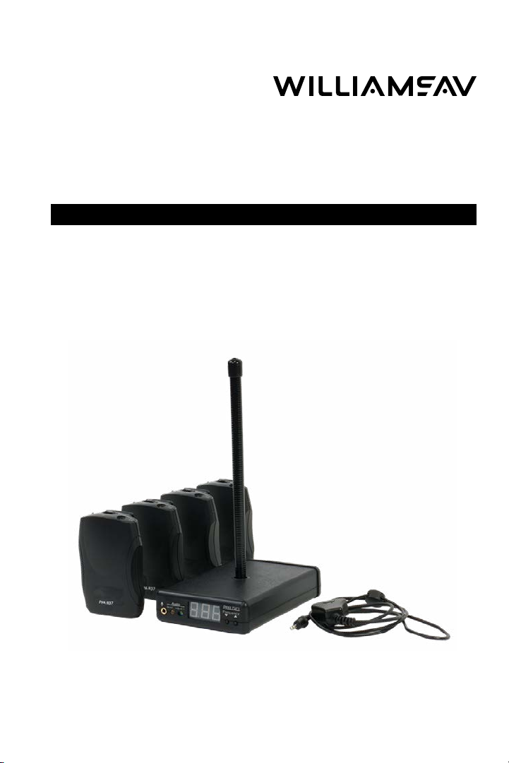
PPA T27
Wide-Band FM Wireless Transmitter
Manual and User Guide
Transmitter Model PPA T27
Optional Receiver Model PPA R38, PPA R37-8
Receiver Model PPA R37
MAN 159H
Page 2

PPA T27
Contents
System Overview ............................................................................................................ 3
Receiver Safety Information......................................................................................... 3
Recycling Instructions .................................................................................................... 4
Setting Up the PPA VP 37............................................................................................. 6
Locking Instructions ........................................................................................................7
Receiver Model PPA R37 Instructions .......................................................................7
Receiver Model PPA R37-8 (optional) Instructions ............................................... 9
Receiver Model PPA R38 (optional) Instructions ................................................... 11
Belt Clip Installation (all Receiver models) .............................................................13
Using A Receiver With A Hearing Aid .....................................................................14
Receiver Management Suggestions .......................................................................14
Earpad Cleaning for Earphones and Headphones ...................................15
Receiver Battery Information ......................................................................................15
Troubleshooting Guide ................................................................................................16
Personal PA Value Pack System Specifications ...................................................18
PERSONAL PA Transmitter Model T27 ..........................................................18
PPA Select™ Receiver (Model PPA R37) ......................................................... 19
Personal PA Receiver (Model PPA R37-8) ................................................... 20
Personal PA Receiver (Model PPA R38) .........................................................21
Lifetime Limited Warranty .......................................................................................... 22
Repair Services ..............................................................................................................23
2
Page 3

System Overview
Thank you for purchasing the PPA T27 FM transmitter which operates in the
72-76 MHz frequency band.
To avoid diculties, please read through these instructions as you begin to
use the system. Save the manual for questions that arise as you continue to
use your system.
If you have any problems with this Williams AV product, please call us tollfree at 1-800-843-3544.
Receiver Safety Information
HEARING SAFETY:
CAUTION!
Any receiver that is used with the T27 transmitter is designed to amplify
sounds to a high volume level which could potentially cause hearing
damage if used improperly.
To protect your hearing and the hearing of others:
1. Make sure the volume is turned down before putting on the earphone or
headphone before adjusting the volume to a comfortable level.
PPA T27
2. Set the volume level at the minimum setting that you need to hear.
3. If you experience feedback (a squealing or howling sound), reduce the
volume setting and move the microphone away from the earphone or
headphone. Do not allow children or other unauthorized persons to have
access to this product.
BATTERY SAFETY AND DISPOSAL:
CAUTION!
Any receiver that is used with the T27 transmitter may be supplied with
alkaline batteries. Do not attempt to recharge alkaline batteries, which may
explode, release dangerous chemicals, cause burns, or other serious harm
to the user or product.
3
Page 4
PPA T27
PACEMAKER SAFETY:
CAUTION!
1. Before using the receiver with a pacemaker or other medical device, consult
your physician or the manufacturer of your pacemaker or other medical
device.
2. If you have a pacemaker or other medical device, make sure that you are
using this product in accordance with safety guidelines established by your
physician or the pacemaker manufacturer.
Recycling Instructions
Help Williams AV protect the environment! Please take the time to dispose
of your equipment properly.
Product Recycling
Please do NOT dispose of your Williams AV equipment in the
household trash. Please take the equipment to an electronics recycling
center; OR, return the product to the factory for proper disposal.
Battery Recycling
Please do NOT dispose of used batteries in the household trash.
Please take the batteries to a retail or community collection point for
recycling.
4
Page 5
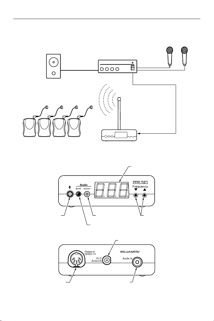
Figure 1: Overall System Diagram
PPA T27
LOUDSPEAKER
PPA SELECT™ RECEIVERS
WITH EARPHONES
Figure 2: PPA T27 Features and Controls
SOUND SYSTEM
AMPLIFIER
RUBBER DUCKIE
ANTENNA
PPA T27 TRANSMITTER
FREQUENCY
DISPLAY (LED)
MICROPHONES
LINE-LEVEL OUTPUT
LINE-LEVEL INPUT
MIC INPUT
JACK, 3.5 MM
12VAC POWER
INPUT JACK
AUDIO LEVEL
CONTROL
AUDIO LEVEL
INDICATOR
75 OHMS ANTENNA CONNECTOR
AUDIO INPUT JACK, RCA-TYPE
(LINE LEVEL,UNBALANCED)
FREQUENCY
SELECTOR
LOCK/UNLOCK
CONTROL
5
Page 6

PPA T27
Setting Up the PPA VP 37
1. Select Location. Position the PPA T27 transmitter near the audio source
(i.e. sound system, etc.) from which it will receive audio.
2. Install the Antenna. Gently thread the rubber duckie antenna (ANT 021)
onto the antenna connector (see Figure 2) on the transmitter.
To use a remote antenna, the antenna cap may be removed by turning it
counter-clockwise with a pliers or wrench.
Note: FCC rules allow only the use of antennas provided by Williams AV. Please
call customer service 800.843.3544 if you have any questions.
3. Connect the Power. Plug the power supply cord (TFP 036) connector
into the “Power In” jack located in the back of the T27. Plug the power
supply into the AC outlet.
On power up, the number 8 will scroll across the T27 display while
the system initializes. The system will then display the default system
frequency (72.9 MHz), or the last selected frequency set by the user.
4. Select the Frequency. The T27 has 17 available channels in the 72-76
MHz band. By default, the T27 frequency is set to 72.9 MHz. To change
the frequency on the T27, press and release the down or up buttons
until the desired frequency is displayed. After 3 seconds, the frequency
selection will be set, and the audio will begin transmitting on the new
frequency.
NOTE: You can LOCK this selection to prevent others from accidently changing
the frequency. See Locking Instructions for further details.
5. Connect the Audio Source. On the back of the T27, an Audio In jack is
available for connecting a line-level, unbalanced audio source. On the
front of the T27, a Mic Input jack is available to connect a Williams AV
microphone. Connect the desired audio source to the T27 transmitter.
6. Adjusting the Audio Source. With the audio source playing, use
a small screwdriver or tuning wand to rotate the Adjust control on
the front of the T27. Turn it clockwise to increase the audio level, or
counterclockwise to decrease the audio level. Refer to the audio level
indicator LED on the front of the T27 as you make your adjustments.
Figure 3: Audio Level Indicator LED
Never On = Audio source is TOO LOW.
Blinks occasionally = Audio source is OPTIMAL.
6
Always on = Audio source is TOO HIGH.
Page 7
7. Listen with an FM Receiver.
IMPORTANT: The FM receiver being used with the T27 transmitter will
need to be on the same frequency as the transmitter.
Install the receiver batteries, plug in the earphone, turn on the receiver and
walk around the listening area. The signal should be clear and quite loud
when the volume is turned up.
Locking Instructions
To LOCK the desired frequency, press and hold both down and up
frequency selector buttons for 3 seconds until the word Loc appears on the
display. The frequency is now locked. Should the user press the frequency
selector button while in Lock mode, the word Loc will be displayed for 2
seconds. The transmitting channel will remain unchanged.
To UNLOCK the desired frequency, press and hold both down and up
frequency selector buttons for 3 seconds until the transmitter displays
Un then Loc on the display. The frequency is now unlocked and can be
changed as needed.
Receiver Model PPA R37 Instructions
PPA R37 is a 17-channel receiver operating on the 72-76 MHz bandwidth.
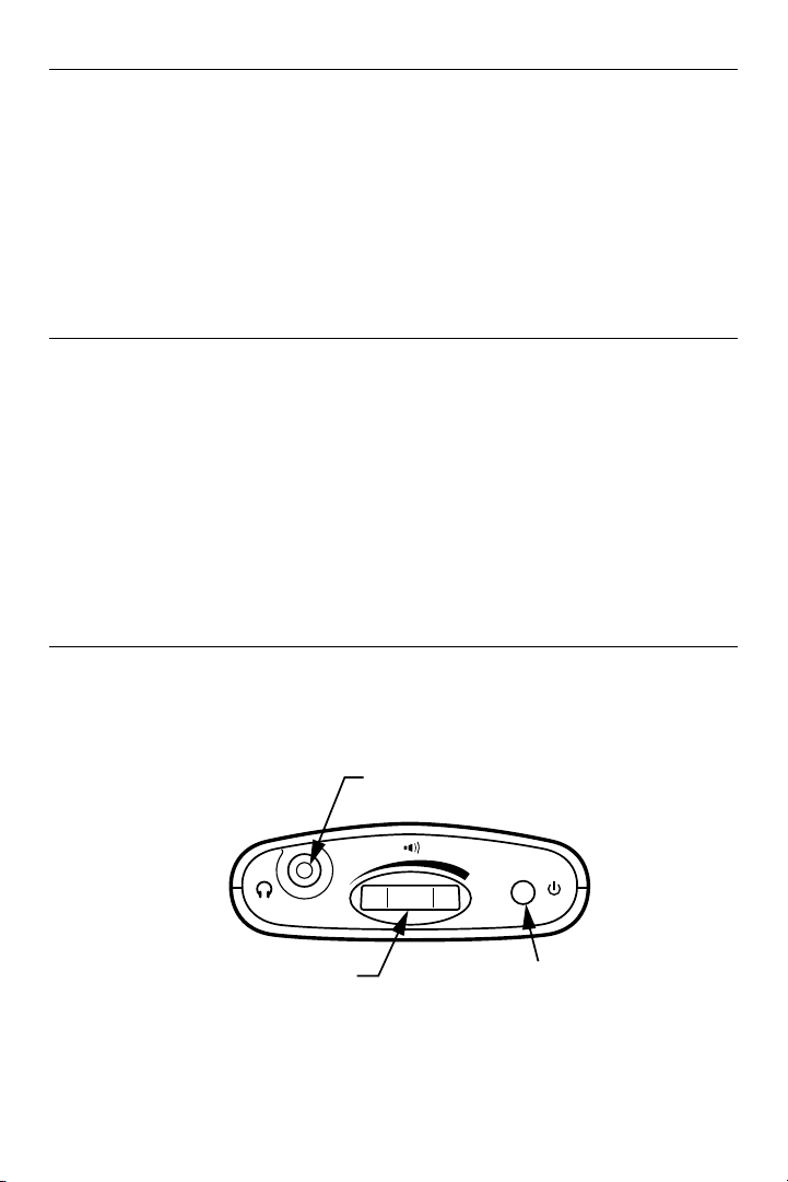
Figure 3: PPA R37 Controls
PPA T27
ON/OFF, VOLUME
CONTROL SWITCH
EARPHONE
JACK
OFF
"ON" / LOW BATTERY/
FLASH CODE INDICATOR
7
Page 8
PPA T27
Operating the Receiver
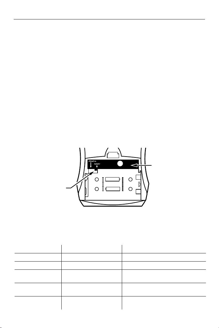
1. Insert two (2) AA batteries, ensuring correct polarity. If rechargeable NiMH
batteries are to be used, make sure the Alkaline/NiMH switch inside the
battery compartment is set to NiMH before charging. See Figure 4.
2. Insert headphone, earphone or neckloop into the stereo output jack.
3. Turn receiver on by turning up the volume control. The green power LED will
blink and then stay on continuously. See Table 1.
4. Set receiver frequency to match transmitter frequency. Press the Channel
Seek button inside the battery compartment once to seek an active
transmitter. See Figure 4. If more than one transmitter is being used, you will
need to push the seek button additional times until you locate the signal you
want to hear. The receiver will retain the channel setting when the unit is
turned o.
Figure 4: Battery and Channel Selections
Channel
Seek
CHANNEL
SEEK BUTTON
ALKALINE/
AA
–
+
+
AA
–
NiMH SWITCH
5. To lock or unlock a selected channel, turn the power o. While holding the
seek button, turn the power back on. When locked, the receiver will remain
on the current channel, regardless of channel seek button presses.
Table 1: LED Flash Codes
Light Code Indicates Description
1 blink Channel locked Seek press remains on current channel
2 blinks Channel unlocked Seek press tunes to next channel present
3 blinks Channel unlocked; no other
On-O-On-O...
(continuous)
Fade-on, Fade-o...
(continuous)
8
channels present
Batteries are low Batteries need to be replaced or
No transmitter present on
current channel
Seek press attempts to find another
channel
recharged
Sleep/Power Save mode (extends battery
life)
Page 9
Receiver Model PPA R37-8 (optional) Instructions
The PPA R37-8 is an eight channel receiver, operating on 72-76 MHz
bandwidth.
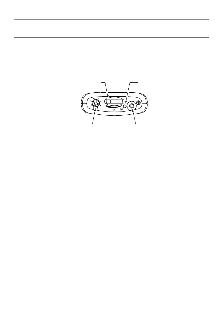
Figure 5: PPA R37-8 Controls
PPA T27
ON/OFF, VOLUME
CONTROL DIAL
CHANNEL
SELECTOR
KNOB
OFF
"ON"/LOW
BATTERY
INDICATOR
HEADPHONE
JACK
Battery Installation
Install two (2) AA alkaline or Nickel–metal hydride (NiMH) rechargeable
batteries. Open the battery compartment by lifting the tab on the back of
the receiver with a finger. To remove batteries, pull up on the fabric strip.
If Alkaline (or non-rechargeable) batteries are being installed, slide the
battery selection switch above the battery compartment to the Alkaline
position. If installing NiMH (or rechargeable) batteries, slide the battery
selection switch to the NiMH position.
Press the batteries into place over the fabric strip. Be sure to observe
proper polarity (+/-). Close the battery door.
Important: Damage due to improper battery installation may void the
warranty on the product.
The red LED on indicator on top of the unit will flash to indicate low battery.
When the sound becomes weak or distorted, replace or recharge the
batteries.
Connecting Earphones
Plug the earphone into the headphone jack on the top of the unit.
Williams AV can only assure optimum performance when Williams AV
earphones and headphones are used.
9
Page 10

PPA T27
Operating the Receiver
Turn the receiver on by rotating the volume control knob. The on indicator
should illuminate red. Refer to the channel selection chart in Table 2 to
choose from 8 standard frequencies.
Turn the channel selector knob to the
desired channel. Make sure the receiver
frequency matches the transmitter
frequency.
Adjust the volume to a comfortable
listening level. To turn the receiver o,
rotate the Volume control knob to the
left until it clicks o. The ON indicator
should not be lit. To prolong the battery
life of the unit, turn the receiver o
when it is not in use.
The on/low battery indicator (Figure 5)
is used to indicate: power, low batteries
or sleep mode. Refer to flash codes in
Table 3.
Table 3: PPA R37-8 LED Flash Codes
LIGHT CODE INDICATES REMEDY
On-O-On-O
(continuous)
Fade-on, Fade-o
(continuous)*
On Steady
*The R37-8 returns to normal operation automatically when a transmitter is re-established on the same channel.
Low Batteries Replace or recharge batteries
No transmitter on
current channel*
Unit is operating
normally
After 6 min, Sleep/power save mode starts (extends
battery life)*
n/a
Table 2: Channel Selection Chart
Freq. (MHz) Channel R37-8 CH
72.1 A 1
72.2 K
72.3 B 2
72.4 N
72.5 C
72.6 O 3
72.7 D
72.8 P 4
72.9 E
74.7 I 5
75.3 J
75.4 R 6
75.5 F
75.6 S
75.7 G 7
75.8 T
75.9 H 8
The stereo headphone jack accepts either stereo or mono headphones or
earphones.
The adjustable squelch can help reduce user fatigue by turning o the
audio when the signal becomes weak. If the operator is annoyed or
fatigued by noise, turn the squelch up. This will reduce the eective range
of the receiver as a trade-o to listener comfort. Similarly if the operator
needs more range and can tolerate the noise, turn the squelch down*.
To adjust the squelch: using a small screwdriver, turn the knob to the right
for more squelch; left for less squelch.
*As the radio signal decreases, the noise present at the headphones increases. The squelch circuit senses the
signal level and turns o the audio as the noise increases. More squelch means this trigger point occurs earlier; less
squelch means it occurs later (or not at all, with no squelch). Apparent range is also aected. More squelch reduces
the apparent range; less squelch increases the apparent range.
10
Page 11
Receiver Model PPA R38 (optional) Instructions
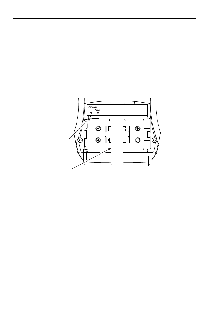
FABRIC STRIP
The PPA R38 is a 17-channel receiver, operating on 72-76 MHz bandwidth.
1. Open the battery compartment. Slide the battery selection switch to the
correct position for the type of batteries that will be used. Use Alkaline for
non-rechargeable batteries. Use NiMH for rechargeable NiMH batteries only.
IMPORTANT: If the battery switch is not in the correct position, damage
may be caused to the unit.
Figure 6: Battery Compartment
CAUTION: RECHARGE
ONLY NiMH BATTERIES
ALKALINE/NiMH
BATTERY SWITCH
BATTERY REMOVAL
PPA T27
1. Install the AA batteries. Be sure to observe proper polarity (+/-). Damage
due to improper battery installation may void the warranty on the product.
The power button on top of the unit will flash when the batteries are getting
low; you may continue to use until the unit quits operating, then replace or
recharge the batteries.
2. Turn the unit on: press and hold the power button for three seconds. The
power button will illuminate green.
3. Select the desired operating channel/frequency on the transmitter. Up to
eight transmitters can operate simultaneously on dierent channels (see 8
channel mode in Table 4.
11
Page 12
PPA T27
T46 FRONT
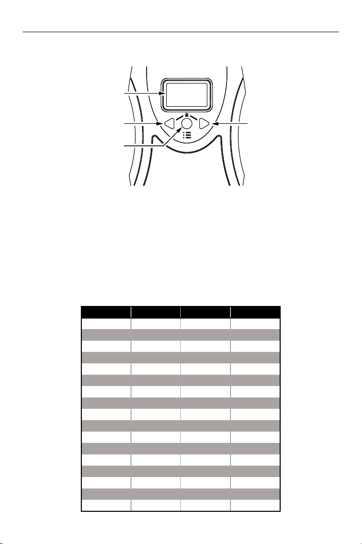
Figure 7: Front of Receiver
OLED
DISPLAY
LEFT
ARROW
BUTTON
MENU
BUTTON
4. Change the receiver to the channel/frequency chosen in step 3. Push the
menu button once and select the channel by pushing the left or right arrow
buttons. (Figure 7).
If the currently broadcasting channel is unknown, use the seek function to find
it by pushing and holding the right or left arrow button. The receiver will stop
when it finds an active channel. If multiple channels are active, repeat the
seek function until the desired channel/frequency is found.
Table 4: Channel Selection Chart
17 Ch Mode Letter Freq (MHz) 8 Ch Mode
1 A 72.1 1
2 B 72.3 2
3 O 72.6 3
4 P 72.8 4
5 I 74.7 5
6 R 75.4 6
7 G 75.7 7
8 H 75.9 8
9 C 72.5
10 K 72.2
11 N 72.4
12 D 72.7
13 E 72.9
14 J 75.3
15 S 75.6
16 T 75.8
17 F 75.5
12
RIGHT
ARROW
BUTTON
Page 13
PPA T27
R38 TOP
5. To access additional settings, push and hold the menu button. The receiver
will display Loading Advanced Setup. After viewing or changing a setting,
push the menu button again to access the next setting. If no buttons are
pushed during the screen time-out period (adjustable in menu), the display
returns to the main screen, and then shuts o to conserve battery power.
The receiver remains on.
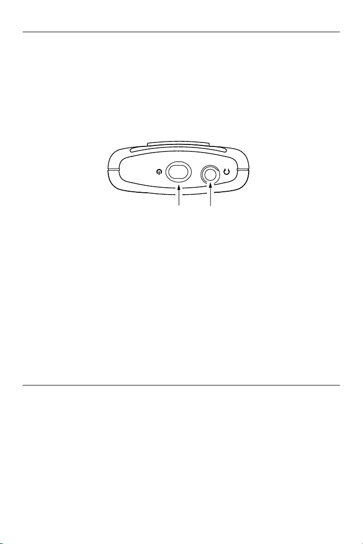
Figure 8: Top of Receiver
POWER BUTTON/
LOW BATTERY
INDICATOR
3.5mm
STEREO/MONO
HEADPHONE
JACK
6. Plug in the earphones/headphones into the headphone jack (Figure 8). The
earphone/headphone cord functions as the antenna.
7. Adjust the volume by pushing the left or right arrow buttons (Figure 7).
8. To lock or unlock all of the settings (except volume), push and hold the left
and right arrow buttons. Three dashes will appear and then disappear. Keep
holding the buttons until the last dash disappears, and the screen prompts
to push the menu button. After pushing the menu button the receiver will
display Settings Locked (or Unlocked).
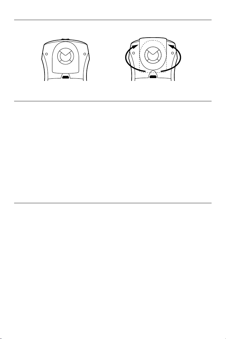
Belt Clip Installation (all Receiver models)
To Install:
Position the belt clip on the rear of the PPA R37, PPA R37-8, or PPA R38
receiver as shown in Figure 9. Turn the belt clip 180º left or right as shown
in Figure 9. The belt clip is now installed and ready for use.
To Remove:
Turn the belt clip 180º so the edge points toward the top of the unit as
shown in Figure 9. Gently pull the belt clip away from the unit to remove.
13
Page 14
PPA T27
Figure 9: Belt Clip Installation and Removal
Using A Receiver With A Hearing Aid
Williams AV PPA R37, PPA R37-8 and PPA R38 receivers can be used with
hearing aids using three dierent methods:
Neckloop Telecoil Coupler
Neckloops are cords which hang around the neck and couple magnetically
with T-coil equipped hearing aids.
Silhouette Telecoil Coupler
These telecoil couplers are worn behind the ear, right next to telecoilequipped hearing aids.
Direct Audio Input (DAI) Cord
Direct Audio Input cords can be used with compatible hearing aids as well
as with Cochlear Implant Processors.
Receiver Management Suggestions
Dierent types of facilities will use dierent approaches for receiver
management and earphone sanitation. Below are some options that
customers have used successfully.
• Regular users purchase their own receiver and take care of their own
batteries and earphone.
• Some facilities label the receiver and earphone with the names of
regular users so each person uses the same receiver and earphone.
• Ushers issue receivers to people who request them. Earphones are
sanitized after use. Foam ear cushions can be replaced or washed with a
mild detergent, rinsed thoroughly and air-dried. The EAR 022 Surround
Earphone can be sanitized with an alcohol pad.
• The receivers can be stored in a multiple compartment storage case with
a credit card or driver’s license left as collateral for the receiver.
• Regular users purchase their own earphone or headphone and bring
them to use with receivers at the facility.
14
Page 15

Earpad Cleaning for Earphones and Headphones
Do not immerse the earphone in water or other cleaning agent. Foam pads
may be removed and washed with a mild laundry soap solution, rinsed
thoroughly, and air dried.
You may purchase new foam pads. Call Customer Service for ordering
information: 1-800-843-3544
Receiver Battery Information
Single Use Batteries
When the battery is low on the PPA R37 or PPA R37-8, the power LED on
the top of the unit will blink. On the PPA R38, the battery symbol on the
OLED screen will blink. With other receivers, if the sound becomes weak
or distorted, the battery is low. Replace the battery. The indicator light may
still be on, even with a battery that is weak. Do not leave dead batteries in
the receivers. Battery corrosion is not covered by the Williams AV Limited
Lifetime Warranty.
Recommended Batteries for Receivers
• BAT 001 AA non-rechargeable alkaline batteries
• BAT 026 AA rechargeable NiMH only
Battery Life
• 50 hours for BAT 001 AA non-rechargeable alkaline batteries
• 32 hours for BAT 026 AA rechargeable NiMH batteries
PPA T27
!! IMPORTANT WARNINGS !!
DO NOT ATTEMPT TO RECHARGE ZINC CARBON (“HEAVY DUTY”), ALKA-
LINE, OR LITHIUM BATTERIES!
DO NOT ATTEMPT TO RECHARGE SINGLE-USE BATTERIES!
These batteries may heat up and explode, causing possible injury and damage to the equipment. Avoid shorting the plus and minus battery terminals
together with metal objects. Battery damage and burns can result! Use only
Williams AV supplied chargers and rechargeable batteries!
Further Suggestions
Receivers should NOT be left charging continuously when not in use.
Receivers should always be turned OFF while charging.
15
Page 16

PPA T27
Troubleshooting Guide
Read through the manual and user guide carefully to verify proper setup
and installation of your system.
Transmitter frequency display (LED) not lit.
• Make sure the wall transformer is plugged into the transmitter.
• Make sure the electrical outlet is on.
No sound through receivers.
• If some of the receivers work but others don’t, check for bad batteries or
earphones on the receivers that aren’t working.
• Check to see that the receiver frequency matches the transmitter
frequency. On the transmitter, the frequency is illuminated on the
LED panel on the front of the unit. On the receiver, there may be a sticker
on the inside of the battery door of the receiver. If these frequencies do
not match, adjust them as needed.
• If none of the receivers work, check to see if the power is connected to
the transmitter and the frequency display on the front of the transmitter
is illuminated.
• Check to see if the transmitter is connected properly to the sound
system.
• On the front panel of the T27 transmitter, turn the audio input level
control clockwise using a screwdriver to increase the audio level. Make
sure that the audio light is flashing occasionally but not continuously.
• If you are not using an input signal from a sound system, make sure the
Williams AV microphone is plugged into the Mic jack on the front of the
T27 transmitter.
• Make sure the antenna is installed and connected properly.
Insucient range, good reception near transmitter, poor at a distance
• Check to see if the antenna was installed correctly. If not, correct or
replace the antenna. The signal should be clearly audible at least 100 ft.
within the line-of-site to the transmitter antenna.
• Check to make sure no other transmitters (or other devices) are
transmitting on the same frequency or channel.
16
Page 17

PPA T27
Sound through receivers is loud, but distorted. Noise (room noise or electronic
noise) seems to grow after talking stops. Audio Indicator Light is continuously on.
• On the front of the T27 transmitter, use a screwdriver to turn the audio
level control counter-clockwise. This will decrease the audio level. The
audio indicator light should flash occasionally, but not be lit continuously.
Sound through the receivers is weak and noisy.
• On the T27 front panel, use a screwdriver to turn the audio level control
clockwise. This will increase the input signal strength. The audio
indicator light should flash occasionally.
• Increase the input signal level from the sound system.
Buzzing or humming noise in sound system.
• There is nothing wrong with the T27 Transmitter. One or more pieces
of equipment in the sound system are being disturbed by RF (Radio
Frequency) signals produced by the T27. The most likely suspects are
the amplifier, mixer, or the audio source. The RF energy gets into the
other equipment primarily through the power cord, speaker wires, or
unshielded inputs, all of which can act as antennas. Try the following
steps:
• Move the transmitter away from the other sound equipment.
• Make sensitive equipment more immune to Radio Frequency (RF)
or Electromagnetic Interference (EMI). The manufacturers of your
audio equipment may oer guidance for this purpose. Unless you
have the necessary technical skills, this is best left to a qualified
electronics repair technician.
• Williams AV oers a document giving suggestions for improving
RF immunity in existing audio equipment—Technical Bulletin:
Remedies For Buzz or Hum in Sound System or PPA. This
document is available on our website.
17
Page 18

PPA T27
Personal PA Value Pack System Specifications
PERSONAL PA Transmitter Model T27
*DISCLAIMER: FCC RULES LIMIT USE OF THIS EQUIPMENT TO AUDITORY ASSISTANCE.
Dimensions & Weight: 4.1” W x 6.1” L x 1.3” H (104.1 mm x 154.9 mm x 33 mm)
Power (U.S./Canada): PPA T27: 12VAC, 300mA, 3.2W
Operating
Frequencies:
Frequency Selector: External switches, 17 channels (lockable)
RF Field Strength: Does not exceed 80mV/m @ 3m
Nominal Range: Up to 500 feet (152 m) w/standard ANT 021 “rubber duckie” antenna.
Modulation: FM, 75 kHz deviation (wide–band) max.
Stability: ± .005% over 0-50˚C
Pre-Emphasis: 75 µS
Frequency Response: 85Hz - 14kHz ±3dB
Distortion: 1% Max. THD
Signal to Noise Ratio: 65 dB with PPA R37 Receiver
Microphone Input: 3.5mm mini phone jack, supplies +DC for electret mics
Mic Input Level: 1–10 mV, nominal
Line-Level Input: RCA Jack, Hi Z, unbal.
Line Input Level: .1–1 Vrms, nominal
Input Attenuator: Pot, screwdriver-adjustable
Antenna Outputs: Thread mount for ANT 021 rubber duckie antenna or ANT 025 telescoping
Approvals: FCC, Industry Canada, RoHS, WEEE
Warranty: Lifetime PLUS Limited Warranty, 90 Days on most accessories.
7.8 oz. (221 g)
Color: Black
Power Supply: Wall Mount Class 2 transformer
Input: 105-130 VAC, 50-60 Hz; Output: 12VAC, 800mA, 5-pin DIN
72-76 MHz*: 72.1 (CH A), 72.2 (CH K), 72.3 (CH B), 72.4 (CH N), 72.5 (CH C),
72.6 (CH O), 72.7 (CH D), 72.8 (CH P), 72.9 (CH E), 74.7 (CH I), 75.3 (CH J),
75.4 (CH R), 75.5 (CH F), 75.6 (CH S), 75.7 (CH G), 75.8 (CH T), 75.9 (CH H)
Up to 1000 feet (305 m) w/optional ANT 005 coaxial antenna.
antenna RF connector for ANT 024 dipole or ANT 005 coaxial antenna
NOTE: SPECIFICATIONS SUBJECT TO CHANGE WITHOUT NOTICE.
18
Page 19

PPA Select™ Receiver (Model PPA R37)
Dimensions: 4.1” H x 2.85 W x 1.38” D (104 mm x 72 mm x 35 mm)
Weight: 4.6 oz (130 g) with batteries, 2.6 oz w/o batteries (73g)
Color: Black
Battery Type and Life: Two (2) AA non-rechargeable alkaline batteries (BAT 001), approx. 50
hours battery life
Two (2) AA rechargeable NiMH batteries (BAT 026), 1500 mAh, approx 32
hours battery life
Current Consumption: Nominal 52 mA
Operating Freq.: 17 channels: 72.1, 72.2, 72.3, 72.4, 72.5, 72.6, 72.7, 72.8, 72.9, 74.7, 75.3,
75.4, 75.5, 75.6, 75.7, 75.8 or 75.9 MHz*.
FM Deviation: +75 kHz
De-Emphasis: 75 µS
LED Indicator: Power on: Bright Green. Low Battery: Flashes.
Sensitivity: 2 µV at 12 dB Sinad with squelch defeated
Input Overload: 100 mV
Frequency Response: 200Hz to 15 kHz, ± 3 dB
Signal-to-Noise Ratio: 65 dB at 100 µV
Receive Antenna: Integral with earphone/headphone cord
Audio Output: 35 mW, 16 ohm loadΩ
Output Connector: 3.5 mm stereo phone jack, accepts either stereo or mono plug
Approvals: FCC, Industry Canada, RoHS, WEEE
Warranty: Lifetime PLUS Limited Warranty; 90 on most other accessories
PPA T27
NOTE: SPECIFICATIONS SUBJECT TO CHANGE WITHOUT NOTICE.
19
Page 20

PPA T27
Personal PA Receiver (Model PPA R37-8)
Dimensions: 4.1” x 2.85” x 1.38” (104 x 72 x 35 mm)
Weight: 4.6 oz (130 g) with batteries. 2.6 oz (73 g) without batteries
Color: Black
Two (2) AA non-rechargeable alkaline batteries (BAT 001-2),
Battery Type and Life:
Current Consumption: 42 mA nominal
Temperature Range: – 0 to 50 °C
Channels: 8, accessed via rotary knob on top of unit
Operating Frequencies: 72.1, 72.3, 72.6, 72.8, 74.7, 75.4, 75.7, 75.9 MHz
Modulation: FM, +/- 75 kHz peak deviation
De-Emphasis: 75 µS
LED Indicator: Power: Green; Low Battery: Flashes Green; Sleep mode: Fade-
Sensitivity: 2 µV at 12 dB Sinad with squelch defeated
Input Overload: 100 mV
Frequency Response: 200 – 15 kHz
Signal-to-Noise Ratio: 65 dB min @ 100 uV
Receive Antenna: Integral with earphone/headphone cord
Audio Output: 35 mW max, peak into 16 Ω
Output Connector: 3.5 mm stereo/mono phone jack
Included Earphone: Earbud-type with foam cushion, 3.5 mm plug, 32 Ω
Sleep Mode:
Approvals: FCC, Industry Canada, RoHS, WEEE
Warranty: Lifetime PLUS Limited Warranty; 90 Days on most accessories
approx. 50 hours battery life
Two (2) AA rechargeable NiMH batteries (BAT 026-2), 1500 mAh,
approx. 32 hours battery life
on,Fade-o
Enters sleep mode after approximately 6 mins of no RF signal,
returns to normal operation when a transmitter is re-established on
same channel
NOTE: SPECIFICATIONS SUBJECT TO CHANGE WITHOUT NOTICE.
20
Page 21

Personal PA Receiver (Model PPA R38)
Dimensions: 4.1” x 2.85” x 1.38” (104 x 72 x 35 mm)
Weight: 4.6 oz (130 g) with batteries. 2.6 oz (73 g) without batteries
Color: Black/Silver. Black ABS Plastic case with Aluminum faceplate.
Battery Type and Life: Two (2) AA non-rechargeable alkaline batteries (BAT 001-2),
Current Consumption: 47 mA nominal at 2.4 VDC
Operating Temp. Range: 32° – 122° F (0° to 50° C)
Channels: 17 Wideband, accessed via menu
Operating Frequencies: 72.1, 72.2, 72.3, 72.4, 72.5, 72.6, 72.7, 72.8, 72.9, 74.7, 75.3, 75.4,
FM Deviation: 75 kHz
De-Emphasis: 75 µS
Display Screen: 1” OLED
Power Indication: Power button, backlit green.
Sensitivity: 2 µV at 12 dB Sinad with squelch defeated
Input Overload: 100 mV
Frequency Response: 200 Hz – 15 kHz, ±3 dB
Modulation: FM, +/- 75 kHz peak deviation
Signal-to-Noise Ratio: Minimum 65 dB @ 1.0 V
Receive Antenna: Integral with earphone/headphone cord
Audio Output: 35 mW max at 16 Ω
Headphone Connector: 3.5 mm stereo jack, mono output for stereo or mono earphones,
Power Save - Display O/Sleep
Mode/Auto-O:
Soft Audio Turn-On: Upon Power ON or Channel Change, mutes audio, then ramps
Approvals: FCC, Industry Canada, RoHS, WEEE
Warranty: Lifetime PLUS Limited Warranty; 90 Days on most accessories.
NOTE: SPECIFICATIONS SUBJECT TO CHANGE WITHOUT NOTICE.
approx. 50 hours battery life
Two (2) AA rechargeable NiMH batteries (BAT 026-2), 1500
mAh, approx. 32 hours battery life
75.5, 75.6, 75.7, 75.8, 75.9 MHz*
Good battery strength - glows solid. Low battery - slow flashes.
Error - fast flashes with 1 sec delay.
headphones, or neckloops
Display O: 5, 30, or 60 seconds of no button pushes
(adjustable in menu)
Sleep Mode: 6 mins of no RF signal or button pushes; wakes up
with RF Signal or any button push
Auto O: 2 hours of no RF signal or button pushes
up 1 numeric step per 1/10th second until set volume is reached
PPA T27
21
Page 22

PPA T27
Lifetime Limited Warranty
Williams AV products are engineered, designed, and manufactured under carefully
controlled conditions to provide you with many years of reliable service.
Williams AV warrants the Personal PA® FM Listening transmitters and receivers against
defects in materials and workmanship under normal use and conditions for the useful
lifetime of the product from date of purchase.
This warranty is available to the original end purchaser of the product and CAN BE
transferred to subsequent purchasers of the product.
Microphones, earphones, headphones, batteries, chargers, cables, carry cases, and
most other accessory products carry a 90-day warranty.
Williams AV has no control over the conditions under which this product is used.
Williams AV, therefore, disclaims all warranties not set forth above, both express
and implied, with respect to the Personal PA® FM Listening System, including but not
limited to, any implied warranty of merchantability or fitness of use of such equipment
including, without limitation, any warranty that the use of such equipment for any
purpose will comply with applicable laws and regulations. Williams AV shall not be
liable to any person or entity for any medical expenses or any direct, incidental or
consequential damages caused by any use, defect, failure or malfunctioning of the
product, whether a claim for such damages is based upon warranty, contract, tort or
otherwise, the sole remedy for any defect, failure or malfunction of the products is
replacement of the product. No person has any authority to bind Williams AV to any
representation or warranty with respect to the Personal PA® FM Listening System.
Unauthorized repairs or modifications will void the warranty. This warranty is void if
damage occurred because of misuse, or if the product has been repaired or modified
by anyone other than a factory authorized service technician. Warranty does not
cover normal wear and tear on the product or any other physical damage unless
the damage was the result of a manufacturing defect. Williams AV is not liable for
consequential damages due to any failure of equipment to perform as intended.
Williams AV shall bear no responsibility or obligation with respect to the manner of
use of any equipment sold by it.
This warranty does not cover reimbursement for your costs of removing and
transporting the product for warranty service evaluation or installation of any
replacement product provided under this warranty.
The exclusions and limitations set out above are not intended to, and should not be
construed so as to contravene mandatory provisions of applicable law. If any part or
term of this Disclaimer of Warranty is held to be illegal, unenforceable, or in conflict
with applicable law by a court of competent jurisdiction, the validity of the remaining
portions of this Disclaimer of Warranty shall not be aected, and all rights and
obligations shall be construed and enforced as if this Limited Warranty did not contain
the particular part or term held to be invalid. The terms of the warranty are governed
by the laws of the State of Minnesota.
Prices and the specifications of the products are subject to change without notice.
22
Page 23

Repair Services
If you experience diculty with your system, call Toll-Free for
customer assistance:
1-800-843-3544 (U.S.A.) or 1-952-943-2252 (World)
If it is necessary to return the system for service, your Customer Service
Representative will give you a Return Authorization Number (RA) and
shipping instruction.
Pack the system carefully and send it to:
Williams AV
Attn: Repair Dept.
10300 Valley View Rd
Eden Prairie, MN 55344 USA
Your warranty becomes eective the date you purchase your system. You
may register your product online:
https://williamsav.com/support/warranty-product-registration/
This information will help us serve you better in the future. Thank you!
PPA T27
23
Page 24

Model PPA VP 37 Wide-Band FM Wireless Listening System
[email protected] / www.williamsav.com
800-843-3544 / INTL: +1-952-943-2252
©2022 Williams AV, LLC• All Rights Reserved
MAN 159H
 Loading...