

Page 1
IR +
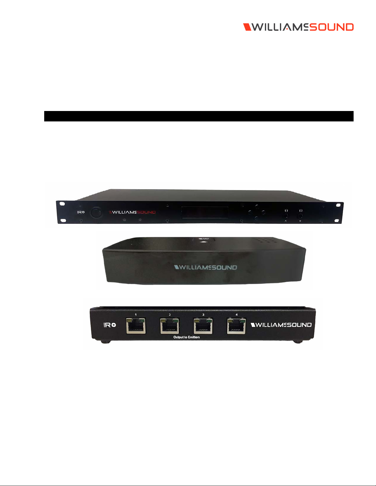
Infrared and Wi-Fi Assistive Listening System
USER MANUAL
MAN 273B
Page 2

IR Plus Assistive Listening System
Table of Contents
Safety Warnings and Instructions �����������������������������������������������������������������������������������������������������������������������������������������������������������������������������������������������4
Avertissements et instructions de sécurité ����������������������������������������������������������������������������������������������������������������������������������������������������������������������������� 4
Recycling Instructions ���������������������������������������������������������������������������������������������������������������������������������������������������������������������������������������������������������������������6
System Overview ������������������������������������������������������������������������������������������������������������������������������������������������������������������������������������������������������������������������������ 6
Wi-Fi Network Required �����������������������������������������������������������������������������������������������������������������������������������������������������������������������������������������������������������������6
Router and Network Equipment Selection ������������������������������������������������������������������������������������������������������������������������������������������������������������������������������6
Quick Setup Guide ��������������������������������������������������������������������������������������������������������������������������������������������������������������������������������������������������������������������������� 7
IR M1 Front and Back Panel ����������������������������������������������������������������������������������������������������������������������������������������������������������������������������������������������������������� 7
Front Panel �������������������������������������������������������������������������������������������������������������������������������������������������������������������������������������������������������������������������������� 7
Back Panel �������������������������������������������������������������������������������������������������������������������������������������������������������������������������������������������������������������������������������� 8
Additional Devices ��������������������������������������������������������������������������������������������������������������������������������������������������������������������������������������������������������������������������� 9
Device Types ���������������������������������������������������������������������������������������������������������������������������������������������������������������������������������������������������������������������������� 9
Wiring and Cabling �����������������������������������������������������������������������������������������������������������������������������������������������������������������������������������������������������������������9
IR E4 ����������������������������������������������������������������������������������������������������������������������������������������������������������������������������������������������������������������������������������������������9
IR A4 ������������������������������������������������������������������������������������������������������������������������������������������������������������������������������������������������������������������������������������������� 10
Installation Instructions �����������������������������������������������������������������������������������������������������������������������������������������������������������������������������������������������������������������10
Determine Coverage Area ������������������������������������������������������������������������������������������������������������������������������������������������������������������������������������������������10
Determine Location ��������������������������������������������������������������������������������������������������������������������������������������������������������������������������������������������������������������11
Network Cable Connection ������������������������������������������������������������������������������������������������������������������������������������������������������������������������������������������������ 11
Cable Connection to Emitters and Emitter Arrays ����������������������������������������������������������������������������������������������������������������������������������������������������� 11
Audio Source Connections �����������������������������������������������������������������������������������������������������������������������������������������������������������������������������������������������12
Multi-Channel Sources �������������������������������������������������������������������������������������������������������������������������������������������������������������������������������������������������������� 12
Avoiding Hum in the Audio (as a Result of a Ground Loop) ���������������������������������������������������������������������������������������������������������������������������������� 12
System Settings ������������������������������������������������������������������������������������������������������������������������������������������������������������������������������������������������������������������������������� 13
Audio Settings ������������������������������������������������������������������������������������������������������������������������������������������������������������������������������������������������������������������������ 13
Server Description ���������������������������������������������������������������������������������������������������������������������������������������������������������������������������������������������������������������� 14
Audio Channel Name ����������������������������������������������������������������������������������������������������������������������������������������������������������������������������������������������������������14
IR Baseband Output ������������������������������������������������������������������������������������������������������������������������������������������������������������������������������������������������������������� 14
Network Configuration �������������������������������������������������������������������������������������������������������������������������������������������������������������������������������������������������������� 14
2
Page 3

IR Plus Assistive Listening System
Restore Factory Defaults ���������������������������������������������������������������������������������������������������������������������������������������������������������������������������������������������������� 15
Web Control Interface �������������������������������������������������������������������������������������������������������������������������������������������������������������������������������������������������������������������15
Login Page �������������������������������������������������������������������������������������������������������������������������������������������������������������������������������������������������������������������������������15
Status Page ������������������������������������������������������������������������������������������������������������������������������������������������������������������������������������������������������������������������������16
Settings Page �������������������������������������������������������������������������������������������������������������������������������������������������������������������������������������������������������������������������� 17
Audio Page ������������������������������������������������������������������������������������������������������������������������������������������������������������������������������������������������������������������������������18
Upload Image ������������������������������������������������������������������������������������������������������������������������������������������������������������������������������������������������������������������������� 19
Network Page ������������������������������������������������������������������������������������������������������������������������������������������������������������������������������������������������������������������������ 20
Administration Page ������������������������������������������������������������������������������������������������������������������������������������������������������������������������������������������������������������� 21
Front Panel Interface �������������������������������������������������������������������������������������������������������������������������������������������������������������������������������������������������������������������� 22
Main Menu ������������������������������������������������������������������������������������������������������������������������������������������������������������������������������������������������������������������������������ 22
Restoring Defaults ���������������������������������������������������������������������������������������������������������������������������������������������������������������������������������������������������������������� 23
Audio Channel Menu ���������������������������������������������������������������������������������������������������������������������������������������������������������������������������������������������������������� 23
Port Information Screen ����������������������������������������������������������������������������������������������������������������������������������������������������������������������������������������������������� 23
Device Detail Page �������������������������������������������������������������������������������������������������������������������������������������������������������������������������������������������������������������� 23
Locking the Front Panel ����������������������������������������������������������������������������������������������������������������������������������������������������������������������������������������������������� 23
WaveCAST App ������������������������������������������������������������������������������������������������������������������������������������������������������������������������������������������������������������������������������ 24
Connect to Wi-Fi Network ������������������������������������������������������������������������������������������������������������������������������������������������������������������������������������������������� 24
Connecting the App to the Channel ����������������������������������������������������������������������������������������������������������������������������������������������������������������������������� 24
Listening via the App ���������������������������������������������������������������������������������������������������������������������������������������������������������������������������������������������������������� 24
Note on Wi-Fi Assist/Smart Network Switching �������������������������������������������������������������������������������������������������������������������������������������������������������� 24
Troubleshooting ����������������������������������������������������������������������������������������������������������������������������������������������������������������������������������������������������������������������������� 24
Specifications ���������������������������������������������������������������������������������������������������������������������������������������������������������������������������������������������������������������������������������� 28
Mounting Options �������������������������������������������������������������������������������������������������������������������������������������������������������������������������������������������������������������������������� 29
Optional Receivers ��������������������������������������������������������������������������������������������������������������������������������������������������������������������������������������������������������������29
Regulatory Statements �����������������������������������������������������������������������������������������������������������������������������������������������������������������������������������������������������������������30
FCC �������������������������������������������������������������������������������������������������������������������������������������������������������������������������������������������������������������������������������������������� 30
ISED ������������������������������������������������������������������������������������������������������������������������������������������������������������������������������������������������������������������������������������������� 30
VCCI ������������������������������������������������������������������������������������������������������������������������������������������������������������������������������������������������������������������������������������������30
IR M1: 2-Year Warranty Statement ��������������������������������������������������������������������������������������������������������������������������������������������������������������������������������������������� 31
IR E4: 2-Year Warranty Statement �������������������������������������������������������������������������������������������������������������������������������������������������������������������������������������������� 32
IR A4: 2-Year Warranty Statement �������������������������������������������������������������������������������������������������������������������������������������������������������������������������������������������� 33
3
Page 4

IR Plus Assistive Listening System
Safety Warnings and Instructions
WARNING! TO REDUCE THE RISK OF FIRE OR
ELECTRIC SHOCK, DO NOT EXPOSE THIS APPLIANCE TO RAIN
OR MOISTURE.
CAUTION! TO REDUCE THE RISK OF ELECTRIC
SHOCK, DO NOT REMOVE COVER. NO USER-SERVICEABLE
PARTS INSIDE. REFER SERVICING TO QUALIFIED SERVICE
PERSONNEL.
POWER CORD NOTICE FOR INTERNATIONAL
OPERATION - Please call Williams AV Customer Service
at 800.328.6190 to order the appropriate power cord for
the country of use.
Important Safety Instructions:
1. Read and follow these instructions
2. Keep these instructions
3. Clean only with dry cloth.
4. Do not block any ventilation openings. Install in
accordance with the manufacturer’s instructions.
5. Do not install near any heat sources such
as radiators, heat registers, stoves, or other
appliance (including amplifiers) that produce heat.
6. Do not defeat the safety purpose of the polarized
or grounding-type plug. A polarized plug has two
blades with one wider than the other. A grounding
type plug has two blades and a third grounding
prong. The wide blade or the third prong is
provided for your safety. If the provided plug does
not fit into your outlet, consult an electrician for
replacement of the obsolete outlet.
7. Protect the power cord from being walked on
or pinched particularly at plugs, convenience
receptacles, and the point where they exit from
the appliance.
8. Only use attachments/accessories specified by
the manufacturer.
9. Unplug this appliance during lightning storms or
when unused for long periods of time.
10. Power Sources - The appliance should be
connected to a power supply only of the type
described in the operating instructions or as
marked on the appliance.
11. Object and Liquid Entry - Care should be taken so
that objects do not fall and liquids are not spilled
into the enclosure through the openings. Do not
use this appliance near water or expose it to
liquids.
12. Servicing - The user should not attempt to service
the appliance beyond that described in the operating
instructions. All other servicing should be referred to
qualified service personnel.
Precautions:
1. Power – WARNING, BEFORE TURNING ON THE POWER
FOR THE FIRST TIME, READ THE FOLLOWING SECTION
CAREFULLY. The unit is designed for use only with the
line cord of the region in which it will be operated.
2. Voltage Label (Rear Panel) – A label located at the rear
panel power connection indicates the DC power input for
the unit. The label will read 48VDC.
3. Do Not Plug in the input, output, Ethernet, or Dante
connections while the power switch is switched to the
ON position.
4. Do Not Touch the IR M1 with wet hands. Do not handle the
IR M1 or power cord when your hands are wet or damp. If
water or any other liquid enters the IR M1 cabinet, take the
IR M1 to qualified service personnel for inspection.
5. Place the IR M1 in a well ventilated location. Take special
care to provide plenty of ventilation on all sides of the
IR M1 especially when it is placed in an audio rack. If
ventilation is blocked, the IR M1 may over heat and
malfunction. Do not expose the IR M1 to direct sun
light or heating units as the IR M1 internal components
temperature may rise and shorten the life of the
components. Avoid damp and dusty places.
6. Care – From time to time you should wipe o the front
and side panels and the cabinet with a soft cloth. Do not
use rough material, thinners, alcohol or other chemical
solvents or cloths since this may damage the finish or
remove the panel graphics.
Avertissements et instructions de sécurité
AVERTISSEMENT! POUR RÉDUIRE LES RISQUES
D’INCENDIE OU DE CHOC ÉLECTRIQUE, NE PAS EXPOSER
CET APPAREIL À LA PLUIE OU À L’HUMIDITÉ.
MISE EN GARDE! POUR RÉDUIRE LE RISQUE DE
CHOC ÉLECTRIQUE, NE PAS RETIRER LE COUVERCLE.
L’APPAREIL NE CONTIENT AUCUNE PIÈCE RÉPARABLE
PAR L’UTILISATEUR. CONFIER LES RÉPARATIONS À UN
RÉPARATEUR QUALIFIÉ.
AVIS CONCERNANT LE CORDON D’ALIMENTATION
POUR UNE UTILISATION HORS DES ÉTATS-UNIS –
Prière d’appeler le service à la clientèle de Williams AV au
800.328.6190 pour commander le cordon d’alimentation
adapté au pays dans lequel l’appareil va être utilisé.
Consignes de sécurité importantes:
1. Lire ces instructions
2. Conserver ces instructions
3. Nettoyer avec un chion sec uniquement.
4
Page 5

IR Plus Assistive Listening System
4. Ne pas bloquer les évents de ventilation.
Installer conformément aux instructions du
fabricant.
5. Ne pas installer à proximité de sources
de chaleur telles que radiateurs, registres
de chaleur, cuisinières ou autres appareils (y
compris les amplificateurs) qui produisent de
la chaleur.
6. Ne pas supprimer ou contourner la fonction
de sécurité de la fiche polarisée ou de mise
à la terre. Une fiche polarisée a deux broches
dont l’une est plus large que l’autre. Une fiche
de mise à la terre a deux broches et une
troisième broche de mise à la terre. La lame
large ou la troisième broche est fournie à des
fins de sécurité. Si la fiche fournie ne rentre
pas dans la prise, consulter un électricien pour
le remplacement de la prise obsolète.
7. Protéger le cordon d’alimentation contre tout
piétinement ou pincement, en particulier au
niveau des fiches, des prises de courant et de
l’endroit où il sort de l’appareil.
8. Utiliser uniquement les pièces/accessoires
spécifiés par le fabricant.
9. Débrancher cet appareil pendant les
orages ou lorsqu’il n’est pas utilisé pendant de
longues périodes.
10. Sources d’alimentation - L’appareil doit
être connecté à une alimentation électrique
uniquement du type décrit dans le mode
d’emploi ou tel qu’indiqué sur l’appareil.
11. Pénétration d’objets et de liquides - Des
précautions doivent être prises pour que des
objets ne tombent pas et que des liquides ne
soient pas renversés dans le boîtier par les
ouvertures.
11. Réparation et entretien - L’utilisateur ne doit
pas tenter de réparer l’appareil autrement que
de la manière décrite dans le mode d’emploi.
Toute autre tâche d’entretien ou de réparation
doit être confiée à un technicien qualifié.
d’entrée, de sortie, Ethernet ou USB lorsque l’interrupteur
d’alimentation est sur la position de marche.
4. Ne pas toucher le IR M1 avec les mains mouillées. Ne
pas manipuler le IR M1 ou le cordon d’alimentation avec
les mains mouillées ou humides. Si de l’eau ou tout autre
liquide pénètre dans l’armoire du IR M1, confier l’appareil à
un technicien qualifié pour inspection.
5. Placer le IR M1 dans un endroit bien ventilé. Veiller tout
particulièrement à assurer une ventilation susante de
tous les côtés du IR M1, en particulier lorsqu’il est placé
dans un rack audio. Si la ventilation est bloquée, le IR M1
peut surchauer et dysfonctionner. Ne pas exposer le IR
M1 à la lumière directe du soleil ou à des appareils de
chauage, car la température des composants internes du
IR M1 pourrait augmenter et réduire la durée de vie des
composants. Éviter les endroits humides et poussiéreux.
6. Entretien - De temps en temps, essuyer les panneaux
avant et latéraux et le boîtier avec un chion doux. Ne
pas utiliser un matériel abrasif, des diluants, de l’alcool
ou d’autres solvants ou chions contenant des produits
chimiques, au risque d’endommager la finition ou d’eacer
les indications fournies sur le panneau.
Précautions:
1. Alimentation – AVERTISSEMENT: AVANT
DE METTRE L’APPAREIL EN MARCHE POUR LA
PREMIÈRE FOIS, LIRE SOIGNEUSEMENT LA
SECTION QUI SUIT. L’amplificateur est conçu
pour être utilisé uniquement avec un cordon
d’alimentation adaptéà la région dans laquelle
il sera utilisé.
2. Étiquette de tension (panneau arrière) - Une
étiquette située au niveau du raccordement
électrique sur le panneau arrière indique
la puissance consommée CA de appareil.
L’étiquette indiquera 48VDC.
3. Ne pas brancher les connexions
5
Page 6

IR Plus Assistive Listening System
Recycling Instructions
Help Williams AV protect the environment! Please take the time to dispose of your equipment properly.
Product Recycling:
Please do NOT dispose of your equipment or batteries in the household trash. Please take the equipment to an
electronics recycling center for proper disposal.
System Overview
The IR + System uses invisible infrared (IR) light to broadcast speech or music to wireless infrared receivers. Listeners can
also use their own personal electronic devices with Wi-Fi.
The new IR + is designed to support those who want to use their own smartphones and headphones for a more discreet
assistive listening experience. Simplicity is also available for those who want a more traditional assistive listening system with
a dedicated IR receiver and headset. Venues no longer need to choose between providing IR or Wi-Fi assistive listening
systems. IR + supports the iOS and Android WaveCAST Apps and the Wi-Fi Receiver-- in addition to all of the current and
legacy Williams Sound IR receivers.
The system is designed to transmit high quality audio for hearing assistance and language translation applications. Because
the system uses infrared light for transmission, it is not aected by interference from radio equipment and does not interfere
with radio equipment. No FCC license or radio approval is required.
The system can be used with microphones as a stand-alone system, or can be connected to other sound equipment. Infrared
systems generally cannot be used in direct sunlight because of sunlight’s large amount of interfering infrared light.
Note: This equipment has been tested and found to comply with the limits for a Class A digital device, pursuant to part 15
of the FCC Rules� These limits are designed to provide reasonable protection against harmful interference when the
equipment is operated in a commercial environment� This equipment generates, uses, and can radiate radio frequency
energy and, if not installed and used in accordance with the instruction manual, may cause harmful interference to radio
communications� Operation of this equipment in a residential area is likely to cause harmful interference in which case
the user will be required to correct the interference at his own expense�
NOTICE: A plasma monitor can degrade the audio quality of the IR Plus.
Wi-Fi Network Required
The IR M1 connects to the installation location's Wi-Fi Network. It does not provide a network on its own. The Wi-Fi network
will need to be installed and established before the Wi-Fi features of the IR M1 can be used.
Router and Network Equipment Selection
The IR M1 does not come with its own router or networking equipment. It is intended to be set up on an already existing Wi-Fi
network; however, upgrades to your network equipment may be necessary depending on the performance desired from the
IR M1. For instance, a higher-end router may allow more users to connect to your audio stream than using a less robust router.
The Wi-Fi network will need to be accessible to the users who will be listening to the audio. A public or Guest Wi-Fi network
will usually be ideal for ease of accessibility. If the user's devices cannot connect to the network due to security settings, they
will not be able to hear the audio.
Multicast connections are required to use the Wi-Fi features of the IR + system. Not all routers support multicast. Check with
your router's manufacturer to ensure the router you are using supports multicast connections.
The IR + system will put a demand on the network. If the network cannot handle the demand, whether because it is being
used for other networking needs or because the networking hardware is not strong enough, the IR M1 will be unable to reach
it's maximum audience.
When streaming to a small or medium sized audience, a basic networking configuration may suce. When streaming music
using multiple channels (such as having several IR M1 units on your network), a powerful router and network configuration is
more likely to be required.
6
Page 7
IR Plus Assistive Listening System
The WaveCAST Networking Guide is available on the Williams AV website for additional networking tips, and applies to
all Williams AV Wi-Fi assistive listening products.
Multiple Units
Up to 4 WaveCAST systems (including WaveCAST, IR M1, FM+ and more) can be used on the same Wi-Fi network.
Multiple devices will work better on more powerful networks and routers.
The number of servers on the network is visible on the front panel of the IR M1. The number assigned to a specific server
is also visible.
Quick Setup Guide
1. Place your IR M1 Control Center in a location where you will be able to place the IR E4 emitters connected to the IR M1
in the listening area.
2. Plug in the power supply to the power connection on the IR M1.
3. Connect an audio source to the Line/Mic In port for the channel(s) you’d like to use.
4. Connect an Ethernet cable to the ETHERNET port. Connect the other end of the Ethernet cable to a multicast-enabled
router with an internet connection.
5. If using IR A4 emitter arrays, connect the provided IR A4 power supplies to the IR A4s. Connect IR E4s to the ports
on the front of the IR A4 with CAT5e cable. Note: The IR A4 is not rated for use in plenum spaces and will need to be
installed in a plenum box for use in such areas.
6. Connect one or more IR E4 emitters or IR A4 emitter arrays to the Output to Emitter ports on the back of the IR M1 with
a CAT5e cable. No additional power is required for an IR E4.
7. Place the IR E4 emitters in the listening area so that they are above the audience without interference. Multiple IR E4
emitters should be placed apart from one another to expand the coverage area.
8. Turn on the IR M1.
9. On the front panel of the IR M1, an IP address should be displayed. Write down the IP address and go to a computer
that is on the same network as the IR+. If you do not see an IP address, check your network connection.
10. In Chrome or Edge, type the IP address into the URL bar. A webpage for the IR+ system will load. The default
username is admin and the default password is admin.
11. Click the Settings tab. Configure each IR E4 emitter for the channels it will broadcast, and the IR Band the system
should emit.
12. Click the Audio tab and set the audio device type and desired settings for each audio channel.
13. Change other settings as desired.
14. While the audio source is playing sound, take an IR Receiver to the front panel of the IR M1 Control Center. The
front panel of the IR M1 has two small IR emitters for testing, one for each audio channel. Set the receiver to the IR
Baseband channel the audio is playing on to ensure all your settings sound correct. This audio will match the audio
from the IR E4 emitters.
15. For more advanced system setup, please see the full user manual.
IR M1 Front and Back Panel
The IR M1 works as a control center for the IR Plus system. Additional devices, such as emitters, are controlled through
the IR M1.
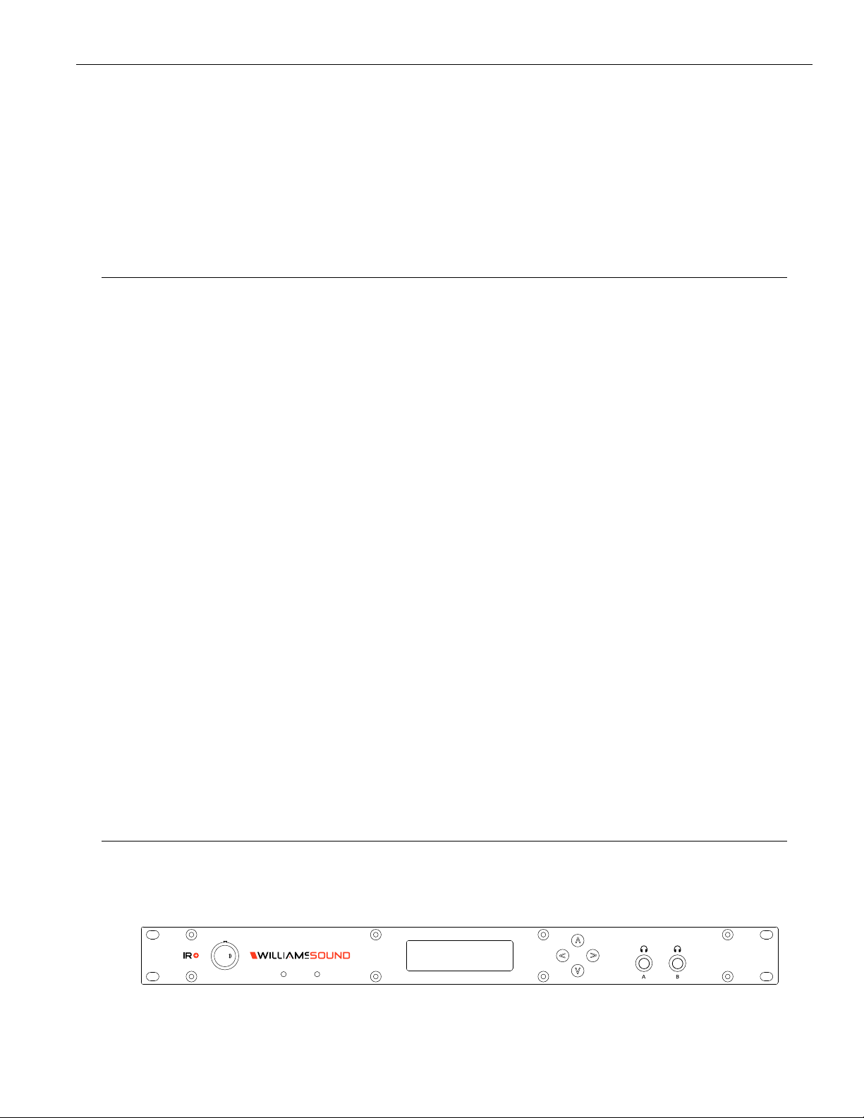
Front Panel
Power Button
The IR M1 has a switch that turns the Control Center on or o. The desktop power supply provides power to the unit at all
times.
7
Page 8
IR Plus Assistive Listening System
OLED Display
This shows current status of channels and of the IR M1. Each time the power of the unit is turned on, the OLED Display shows a
Williams AV start-up screen followed by the firmware blob version number. After several seconds, the default Main Info Screen
screen will be displayed.
Screen Time Out
If no buttons are pressed on the IR M1 for a while, the display will shut o. Pressing any button on the front panel will re-activate
the screen.
Navigating the Front Panel
The arrow buttons (up, down, left and right) on the front panel of the IR M1 are used to navigate the front panel menu. See "Front
Panel Interface" on page 22 for how to use the arrows on each screen.
Headphone Jacks
Two headphone jacks are available on the front panel to listen to the raw audio input, one for channel A and one for channel B.
The headphone jack audio is aected by negative gain, but not any positive gain, compression or filtering adjustments as it is
connected directly to the audio signal source.
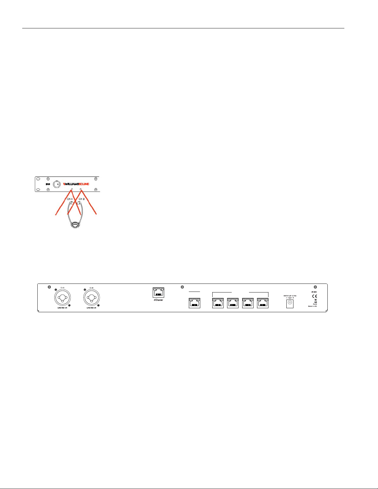
Built in Emitters
Two emitters are built into the IR M1 for testing purposes. These emitters are not strong enough for
sending audio to an audience, but are suitable for testing the device when setting it up. There is
an emitter for audio output channel A and a separate emitter for channel B. Use any applicable
Williams Sound receiver to test the audio. Hold the receiver within a few feet of the IR M1; the
built-in emitter coverage area is not large and is only for testing.
The built-in emitters will not work without an IR E4 emitter connected directly to the IR M1 or a
connected IR A4 with the desired audio channel enabled. For example, if there is an active audio
source on CH A and an emitter with Audio Channel A enabled, the built-in IR emitter on the front
panel will broadcast Audio Channel A on the appropriate IR Baseband Channel (see "IR Baseband
Output" on page 14).
If either Audio Channel is not actively enabled on at least one IR device attached to the M1, the front panel's built-in emitter will not
transmit anything, even if an audio source is present.
Back Panel
ETHERNET
STREAMING
AUDIO OUT
Audio Input
Two audio devices can be connected via the Line/Mic In ports. Each port is for one audio output channel. The source will need to
be set via the web interface or front panel for the IR M1 to configure the gain level for the audio source correctly.
Dante™ (Optional)
An input for connecting to a Dante audio network is available on IR M1 D Control Centers. This feature is not on every model.
Ethernet
The Ethernet connect is for connecting to a network and/or providing an internet connection. No emitters or other devices should
be connected to the Ethernet port.
Output to Emitters
Emitters and expansion arrays are connected to the Output to Emitter ports. There are four ports on the IR M1. These specific ports
will often be referred to as Ports throughout the website and this manual.
Although a standard Ethernet cable is used for these connections, no network information is provided through these ports. Only
approved Williams Sound devices may be connected to the Output to Emitter ports on the back of the IR M1. Use the designated
Ethernet port on the back of the IR M1 for network and internet connections.
Power
Connect the provided power supply to the power port.
Output to Emitters
1 2 3 4
8
Page 9
IR Plus Assistive Listening System
Additional Devices
To create a full IR system, additional devices will need to be connected to the IR M1. Note that devices can be disconnected or
connected to the IR M1 at any time without needing to shut o or power cycle the IR M1.
The IR E4 is an IR Emitter and up to four can be directly connected to the IR M1. The IR A4 is a distributed emitter array, with four
ports available on it. Up to four IR A4's can be connected to the IR M1, letting you connect up to 16 IR E4's to a single IR M1.
Device Types
Several types of devices may be plugged into the IR M1 Control Center. The IR M1 identifies the type of each connected device on
the front panel screen and on the webpage. Not all of these device types are valid and can indicate a problem with the IR + setup
or device.
DEVICE TYPE TYPE CODE MEANING
IR A4 Emitter Array IR A4 Valid Device. This is a distributed emitter array that IR E4's can be
connected to.
IR E4 Emitter IR E4 Valid Device. An IR Emitter.
Unknown UNKWN This type of device is not recognized. There may be a short in
the device that is preventing the system from detecting what it is.
Invalid INVLD This device is not connected in a usable manner. The IR + system
may not have a required firmware update to recognize this
device type, or the connection may be invalid. For example, an IR
A4 cannot have another IR A4 connected to it
None --- Nothing is detected as being plugged into the port.
Wiring and Cabling
CAT5e cables must be used for connecting devices. They are not required to be shielded. The maximum recommended cable
length is 300 ft (91.4 m).
Each CAT5e cable connection from the IR M1 system to the IR E4 emitters carries the following signals:
• Baseband signals for 1 or 2 IR channels
• +48V power supply for the IR E4
• RS-485 bus communications
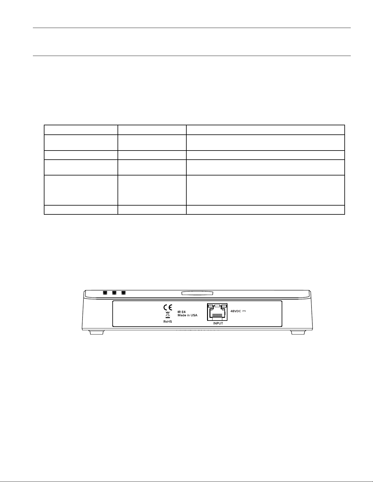
IR E4
Back Panel of IR E4
The IR E4 is connected to the IR M1 via a CAT5e cable. Once connected, any changes required can be made through the IR M1's
webpage.
The IR E4 receives its power from the CAT5e cable and no additional power supply is required.
Note: Although the IR E4 receives power from an Ethernet cable, it does not follow the formal Power over Ethernet (PoE) standard�
9
Page 10
IR Plus Assistive Listening System
0°
10°
0ft/0m
25ft/8m
50ft/15m
75ft/23m
IR + Coverage Pattern
0ft/0m
25ft/8m
50ft/15m
75ft/23m
100ft/30m
125ft/38m
150ft/46m
175ft/53m
200ft/61m
225ft/69m
20°
30°
40°
50°
60°
70°
80°
90°
RX22-4 Receiver
RX20 Receiver
IR A4
The IR A4 is connected to the IR M1 via a CAT5e cable. The IR A4 requires a separate power supply, and does not use the same
power connector as the IR M1.
Once powered on, IR E4's can be connected to the IR A4 via a CAT5e cable, just as if they were connected to an IR M1.
Additional IR A4s cannot be connected to an IR A4. IR A4's can only be connected to the IR M1 itself on the four back ports, so
only four IR A4's can be used at one time.
Note: The IR A4 is not rated for use in plenum spaces and will need to be installed in a plenum box for use in such areas�
Installation Instructions
The IR M1 Control Center is the key component to the IR+ system. Audio devices, emitters, and more can be connected to the IR
M1. This section will cover the installation instructions for physically setting up your IR + system.
Determine Coverage Area
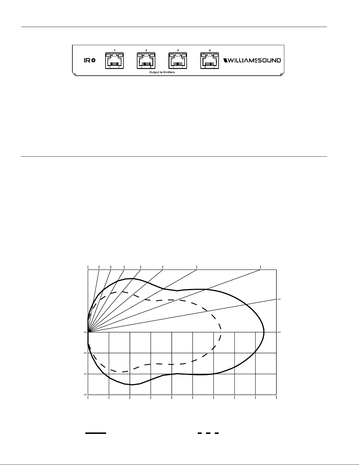
When using the IR + system in single-channel mode with the RX22-4 receiver, the system coverage area will cover up to 18,000
sq. ft. (1,673 sq. m.) per IR E4 emitter. When in two-channel mode, the maximum IR coverage area will drop to accommodate for
broadcasting two dierent audio signals instead of one. Decreasing the emitter power level will also decrease the coverage area.
The IR E4 will use full power, single channel mode by default. Single channel or dual channel mode, and emitter output power, can
be selected using the system webpage.
Connect the number of E4's needed to cover the space required.
Interference
10
Page 11
IR Plus Assistive Listening System
INPUT INPUT
ARRAY (IR A4)
EMITTER (IR E4)
OUTPUT OUTPUT
EMITTER (IR E4)
Connected to
Front Panel
of IR A4
48VDC
ETHERNET
STREAMING
AUDIO OUT
Output to Emitters
1 2 3 4
IR M1 CONTROL CENTER (REAR)
Most objects block infrared light. The coverage area may be aected by direct/indirect sunlight, reflections on walls and room
construction. The emitter cannot be concealed behind walls, glass, curtains, etc. Reflections of the infrared light from walls,
ceilings, and floors may the direct infrared radiation pattern.
The infrared radiation decreases but does not drop to zero outside the illustrated patterns. It still may be usable at a greater
distance, depending on the receiver sensitivity and the reflective characteristics of the room.
Important: Point the emitter towards the listening audience from high up� Bodies can block the infrared signal from reaching various
parts of the audience if at a poorly selected angle�
Do not paint the front face of the IR E4.
Determine Location
The IR M1 Control Center is usually located with the sound system amplifier or mixer for easy access to an audio input signal. For
portable systems, the Control Center can be placed near the emitter(s) or in another convenient location.
Position the IR E4 emitters so the area is well covered and has minimal interference. The emitters should be placed high on
the wall, aimed into the coverage area and angled down toward the audience. For help determining ideal IR coverage area or
avoiding obstacles, contact Tech Blue Design and Support Services (see "Troubleshooting" on page 24).
Network Cable Connection
The Ethernet port can be used to connect the IR M1 to a local network. A network connection is required to access the IR M1
webpage. The webpage is needed to configure some device settings after the system is set up.
An Ethernet connection alone will not allow the Wi-Fi broadcast features to work; a Wi-Fi connection must be available on the
network. However, a network connection is not required for broadcasting over infrared.
Once a connection has been established, an IP address will automatically be assigned to the IR M1 (see the front panel section's
"Front Panel Interface" on page 22 for help finding the IP Address). Device settings can then be set via the web interface,
including changing any network settings.
Cable Connection to Emitters and Emitter Arrays
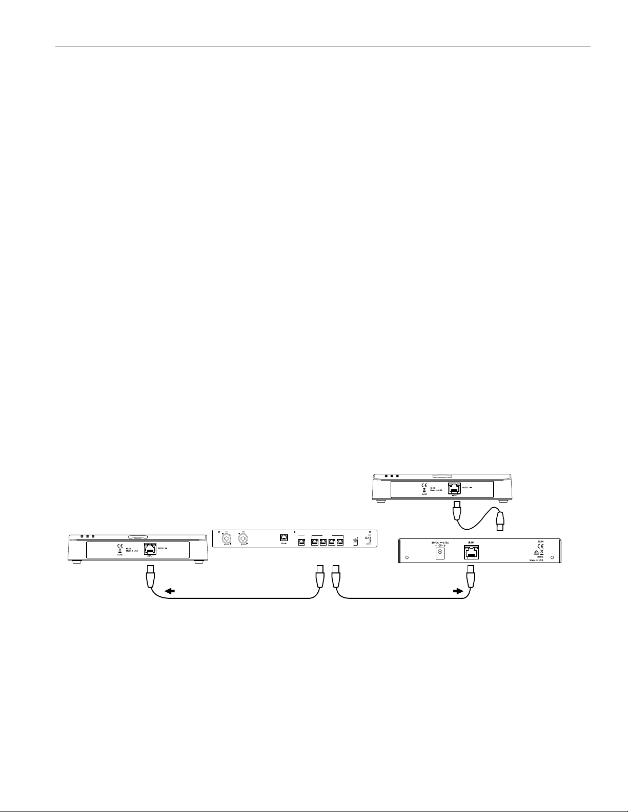
The IR M1 can directly drive four IR E4 emitters without the use of an emitter array. Up to 4 IR A4 emitter arrays can be directly
connected to the IR M1. Up to 16 emitters can be connected with the use of IR A4 emitter arrays.
The outputs MUST NOT be split with CAT5e splitters.
Determine the length of CAT5e cable needed to reach from the Emitter or Emitter Array to the Control Center unit.
11
Page 12
IR Plus Assistive Listening System
BALANCED LINE USING 3–PIN CONNECTOR
IN PHASE
UNBALANCED LINE USING 3–PIN CONNECTOR
BALANCED LINE USING 1/4" CONNECTOR
IN PHASE
UNBALANCED LINE USING 1/4" CONNECTOR
Audio Source Connections
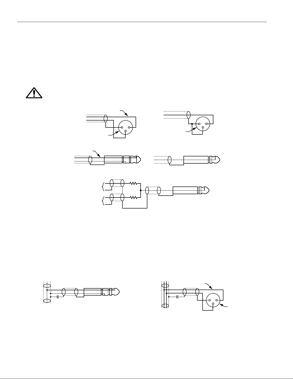
The IR M1 Control Center will accept the following audio sources:
1. Balanced Microphone with or without 12-volt phantom power (DIN 45596) on a 3-pin (XLR) connector.
2. Balanced/Unbalanced microphone with or without phantom power on 1/4 inch (TRS) jack
3. Balanced/Unbalanced Line on a 3-pin (XLR) connector.
4. Balanced/Unbalanced Line on 1/4 inch (TRS) jack.
5. Dante on an RJ-45 jack (optional).
WARNING:
The IR + is not designed to accept 70 volt speaker signals! This may result in damage to your system. The sound source
should come directly from the system mixer or digital source as a low-level or unprocessed signal.
3 PIN CONNECTOR
1 2
3
1 2
3
3 PIN CONNECTOR
4.7 K
SOURCE A
SOURCE B
CONNECTING TO A MULTI-CHANNEL OR STEREO SOURCE
4.7 K
Multi-Channel Sources
By constructing a simple resistive mixer, stereo (or 3 channel) sources can be connected to the IR +. Additional channels can be
accommodated by adding a resistor for each source.
Note: The Dante audio input will automatically mix the left and right channels�
Avoiding Hum in the Audio (as a Result of a Ground Loop)
A hum created by a ground loop can often be eliminated by connecting a capacitor in series with the audio line shield to the IR
M1’s ground. This method also maintains good radio frequency (RF) shielding. Determining the eectiveness of this method for
your installation usually requires some experimentation.
.01 uF CERAMIC DISC
CAPACITOR
BREAKING A GROUND LOOP WHEN
CONNECTING TO A UNBALANCED LINE
12
IN PHASE
1 2
.01 uF CERAMIC
DISC CAPACITOR
BREAKING A GROUND LOOP WHEN
CONNECTING TO A BALANCED LINE
3
3-PIN
CONNECTOR
Page 13

IR Plus Assistive Listening System
System Settings
Most settings are adjusted via the web interface by using a computer (see "Web Control Interface" on page 15). A handful of
settings can be adjusted via the front panel display (see "Front Panel Interface" on page 22).
Any configuration to the IR+ system is done through the IR M1, which passes the configuration setting onto other IR+ devices.
Audio Settings
The Audio Settings provide the ability to change the audio characteristics for dierent listening applications.
Audio Input Source
The Audio Input Source menu has five possible selections to choose from: Line In, Mic In, 400Hz Test Tone, Mic + Phantom Power,
or Dante.
Selecting an Audio Source Appropriate for Hearing Impaired Listeners
The IR + transmits audio with excellent fidelity. Therefore, the audio source signal should be of the highest audio quality and not
subject to a compressor, limiter, reverberation, or other signal processing equipment. While compressed audio is available through
the IR +, excessive compression is not helpful to the hearing impaired and can contribute to excessive noise in the audio.
The IR + audio source signal is usually connected to a mixer’s line output signal which is behind the mixer’s parametric equalizers
but ahead of any equalization used for house loudspeakers.
If audio delay is available for use in large auditoriums, it’s usually best to use it. Because radio signals travel faster than sound,
delaying the transmitted audio so that an average listener (in the middle of the listening area) hears the transmitted audio a few
milliseconds after audio from the main sound reinforcement system speaker is helpful. This will also help audience members who
lip read.
Audio Input Gain
The Audio Input Gain adjusts the audio output level from the IR M1. Changes to the input level will aect the level indicated by the
front panel display when audio is present. The gain can be adjusted from -60dB to +24dB.
NOTE: Negative gain sets the analog attenuator and positive gain sets the digital amplifier� For audio clarity, it is generally best
practice to have the gain set so that it is negative� The VU meters should peak near 0 dB� If using Line In mode, consider
raising the volume at the source to ensure this practice�
Audio Presets
The Audio Presets allow the user to quickly and easily configure the IR M1 for common applications. The audio preset can only be
adjusted via the Web Interface.
There are three pre-configured to choose from: Hearing Assist, Music, and Voice. When one of these selections is made, the
performance of the IR M1 is immediately optimized for the needs of that application (an adjustment is automatically made to the
Low-pass Filter, High-pass Filter, and Compression).
By default, the IR M1 is shipped in the Music mode. For music, concerts, and other applications where the highest audio quality is
desirable, Music is the recommended mode of operation.
For hearing assistance applications, or applications where the message is critical for listening, Hearing Assist is the
recommended mode of operation.
For speaking and other voice applications, Voice is the preferred mode of operation.
A Custom preset is also available for configuring channel-specific audio settings.
Audio Input Level Indicator
The bar graph indicator shows audio level in 3dB steps at the output of the audio level processing circuit. The indicator is peak
responding and is calibrated so that optimum level is reached when the VU meter only fully lit (+9dB) occasionally and typically
hovers around 2/3rds lit (0dB). Adjust the audio levels from the front panel (see "Audio Channel Menu" on page 23)or from the
web interface (see "Audio Page" on page 18).
Input Overload Indication
The OLED Display shows an exclamation mark (!) above each channel's VU meter as an overload warning each time the audio
signal exceeds the capacity of the input circuit. Either the source of the audio coming in to the IR M1 needs to be adjusted to
correct this or the Audio Input Gain needs to be adjusted. A warning will also appear on the web interface if overloaded.
13
Page 14

IR Plus Assistive Listening System
Server Description
The Server Description field allows the user to easily identify the IR M1. This typically comes into play when multiple IR M1s need to
be distinguished from one another. The description appears on the front main info screen, and also on the web page. In a rack, all
the user has to do is activate the main info screen with a touch of any button on the front, and the description is displayed as one
of the fields on the main info screen.
The description can only be edited from the web interface.
Audio Channel Name
The Audio Channel Name allows the listeners to easily identify the channel. The description appears on the on the web page and
in the WaveCAST App. The channel description can only be edited from the web interface.
IR Baseband Output
The IR baseband frequencies will broadcast audio output channels A and B. The frequencies can either be 2.3 MHz for Channel
A and 2.8 MHz for channel B, or be 3.3 MHz for Channel A and 3.8 MHz for Channel B. Which frequencies the IR + system is
broadcasting over is adjustable via the web interface.
On a Williams Sound IR Receiver, the numeric channel numbers on the receiver represent a specific IR frequency. The receiver
should be set to use the channel with the frequency that the audio output channel is being sent over.
IR OUTPUT
CHANNEL
Audio will not output to IR emitters if:
• an audio output channel is muted (silent for too long). This timeout can be adjusted via the web interface.
• no IR Emitter is connected to any port, or any connected emitters are disabled.
• there is no emitter configured to use that channel
Audio will output over Wi-Fi as long as Wi-Fi audio is enabled for that channel.
FREQUENCY
MHZ
1 2.3
2 2.8 B
3 3.3 A
4 3.8 B
AUDIO OUTPUT
CHANNEL
A
LEDs
The LED lights on the Ethernet and Output to Emitter ports can be used to help troubleshoot issues, but may be distracting if
left on during normal usage. These LEDs may be disabled on the via the Web Interface for attached devices, but they cannot be
disabled on the IR M1.
• Green – Communication Active: Flashes as long as there are communications ongoing over that port, otherwise remaining
dark.
• Amber – Channel Signals Present: On the IR M1, the amber light flashes when audio is sent to an attached device. On
attached devices, the amber light flashes when audio is received by the attached device. The flashing will speed up when
both channels are in use. The pacing of the light does not indicate the audio rate, like a VU meter. The light is merely an
indicator that data transfer is occurring. Otherwise, if audio is not being sent or received, the amber light remains dark.
Network Configuration
Network Settings can only be edited from the web interface. An IP address will be automatically assigned to the IR M1 once an
Ethernet cable has been connected between the IR M1 and the router and a network connection has been found. Additional
configuration is made through the web interface.
Adjusting Network Settings
The Network Settings screen where the IP Address Mode, the IP Address, and the Subnet Mask are set via the web interface. See
"Network Page" on page 20 for details on how to use the web interface.
IP Address Mode Static or DHCP
IP Address If the IP Address Mode is set to Static, this is where the IP Address is manually entered
Subnet Mask If the IP Address Mode is set to Static, this is where the Subnet Mask is manually entered
Gateway If the IP Address Mode is set to Static, this is where the gateway is manually entered
Multicast Address If needed, the multicast cast address can be enabled and either manually set. If not manually set, a preset fixed
address will be assigned by the IR M1. This setting is under the Options menu and is set per channel.
DHCP IP Addresses are automatically created, and are usually preferred to a manual static IP address.
14
Page 15

IR Plus Assistive Listening System
To set up a static IP Address:
1. Determine an appropriate static IP address for the IR M1.
a. If someone set up your network, they may be able to help you determine an appropriate IP address (i.e. network system
administrator).
b. There should be no other device having this same address on the network.
c. This will be an address on the same subnet as the router.
For example, if the router’s address is 192.168.1.100, the first three sets of numbers will be the same (i.e. 192.168.1), and the last
number will be the number you decide for the IR M1 (You may choose another number instead of .100).
When you determine this address, write it down for a later step.
2. Set the Static IP Address for the IR M1 via the web interface of the IR M1 (see "Network Page" on page 20).
a. Select the connection type to be Static.
b. Enter the IP Address you determined earlier.
c. Network settings in the IR M1 take place after saving and rebooting.
Restore Factory Defaults
The Restore Factory Defaults action will restore the IR M1 to it’s original factory settings. Restoring defaults from the front panel of
the IR M1 will reset all settings.
On the front panel menu, it is hidden on the main screen ("Main Menu" on page 22).
Restoring defaults from the web page will reset all settings except Network connectivity settings (IP Address, Subnet Mask, IP
Address Mode, and Web Password). The same IP address will most likely be used by the system since no network changes
occurred; however, the device will be oine while it is rebooting. The webpage will need to be refreshed after the system has
restarted to continue adjusting settings.
In the web interface, this feature is under the Admin menu.
Web Control Interface
The IR M1 provides a web interface to manage the device settings. These web pages can be accessed over either a hardwired or
wireless network connection with the Chrome browser.
Changes take eect when applied or saved. Any updates made through the front panel will show up on the web interface once
the current page has been navigated away from, either by refreshing the page or going to a new page.
1. Open Chrome.
2. In the address bar of the browser, type in the IP address of the IR M1 and hit Enter.
3. The web page will say 'Fetching Data' as it connects to the IR M1 and gathers data of every connected machine. This may take
several seconds.
4. You should see the Login Page of the IR M1.
• If you only see a page asking for a firmware update, your device may have been corrupted. See "Website problems" on page
24
Login Page
The default User name is “admin” and the default password is “admin”. The user name and the password can (and should) be
changed on the website's Admin page.
Check with your system administrator for the most recent login credentials.
15
Page 16
IR Plus Assistive Listening System
Status Page
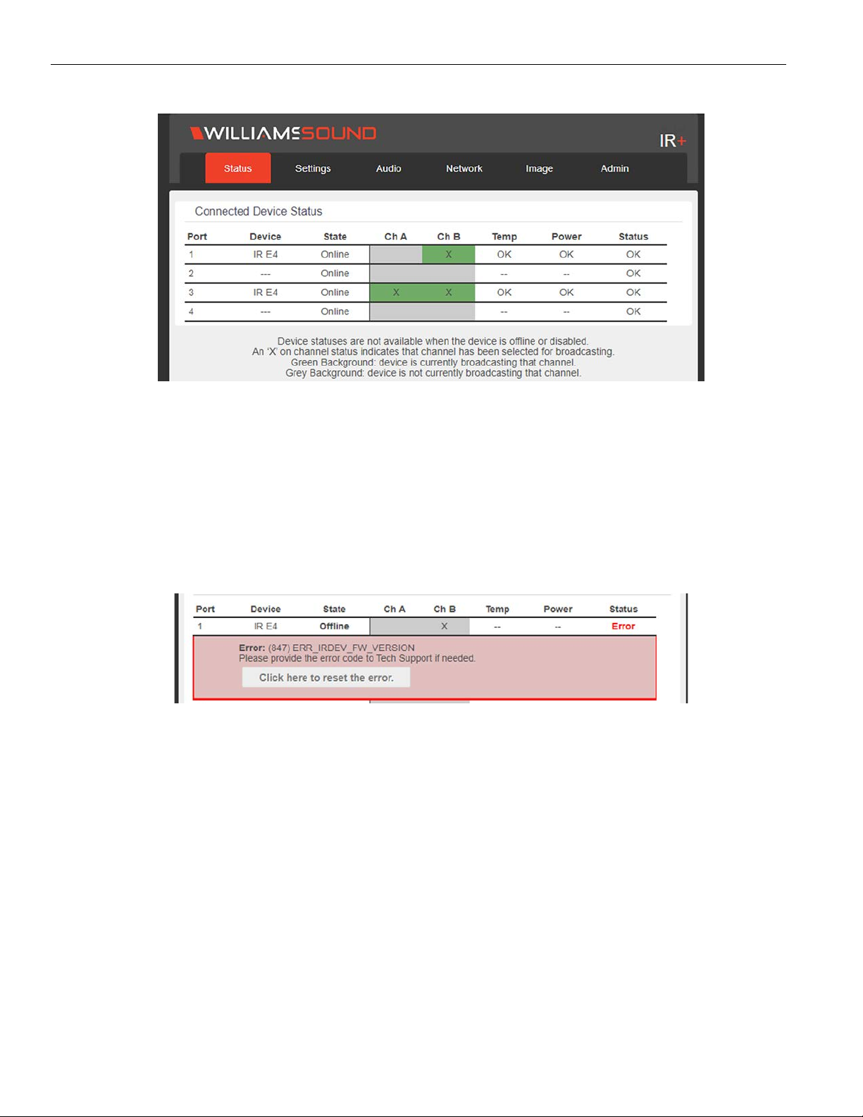
The status screen displays the current status of any devices connected to the IR M1. It displays the port the device is connected to,
the type of device, whether audio is broadcasting over a channel, whether a channel is configured to broadcast audio, and alerts
on the temperature, power level, or other errors.
If a device is oine or disabled, this will be stated in the State column. Oine devices may still be booting or experiencing an
error. Disabled devices are manually set to be disabled on the settings menu. Disabled or oine devices are unable to broadcast.
Online devices are fully available to broadcast. The online or oine status does not indicate any internet or network connectivity.
Rarely, a device type cannot be properly detected. See "Device Types" on page 9 for more information.
Unlike other pages on the website, this page will automatically update after a short delay with new device information when it is
available.
Errors
When an error occurs, the device will automatically switch to oine status (or remain disabled). The system will then report what it
can about the problem that occurred.
Three type of errors are available on the status screen. If a device has overheated, the Temp field will show there is an error. If a
device is having an issue with power, the power field may show an error. There is also an area to display other error information, if
there is an error unrelated to heat or power.
If the device has detailed error information, it will display in a red box under the device information.
The IR M1 can attempt to repair certain errors. When an error appears on the status screen, click the reset the error button. The
connected device may go oine briefly while the system attempts to repair the error.
Not all errors can be corrected automatically; if the error persists, you should contact TechBlue Technical Support Services for help
with your device (see "Troubleshooting" on page 24). When called or e-mailed, TechBlue may ask for the error code or error
number shown in the red information box on the status screen. There may or may not be additional troubleshooting information
available for power or temperature types of errors, and these errors likely cannot be automatically repaired.
Current Status
When a device is oine or disabled, the temp, power and error status cannot be guaranteed to be currently accurate. The system
is reporting the last known status before the device was set into oine mode to help troubleshoot what may have caused the
issue. If the device has not indicated there was an error with temp, power, and/or status, these fields will display '--'.
Once the device is repaired and online again, the current status will be 'OK'.
16
Page 17
IR Plus Assistive Listening System
Settings Page
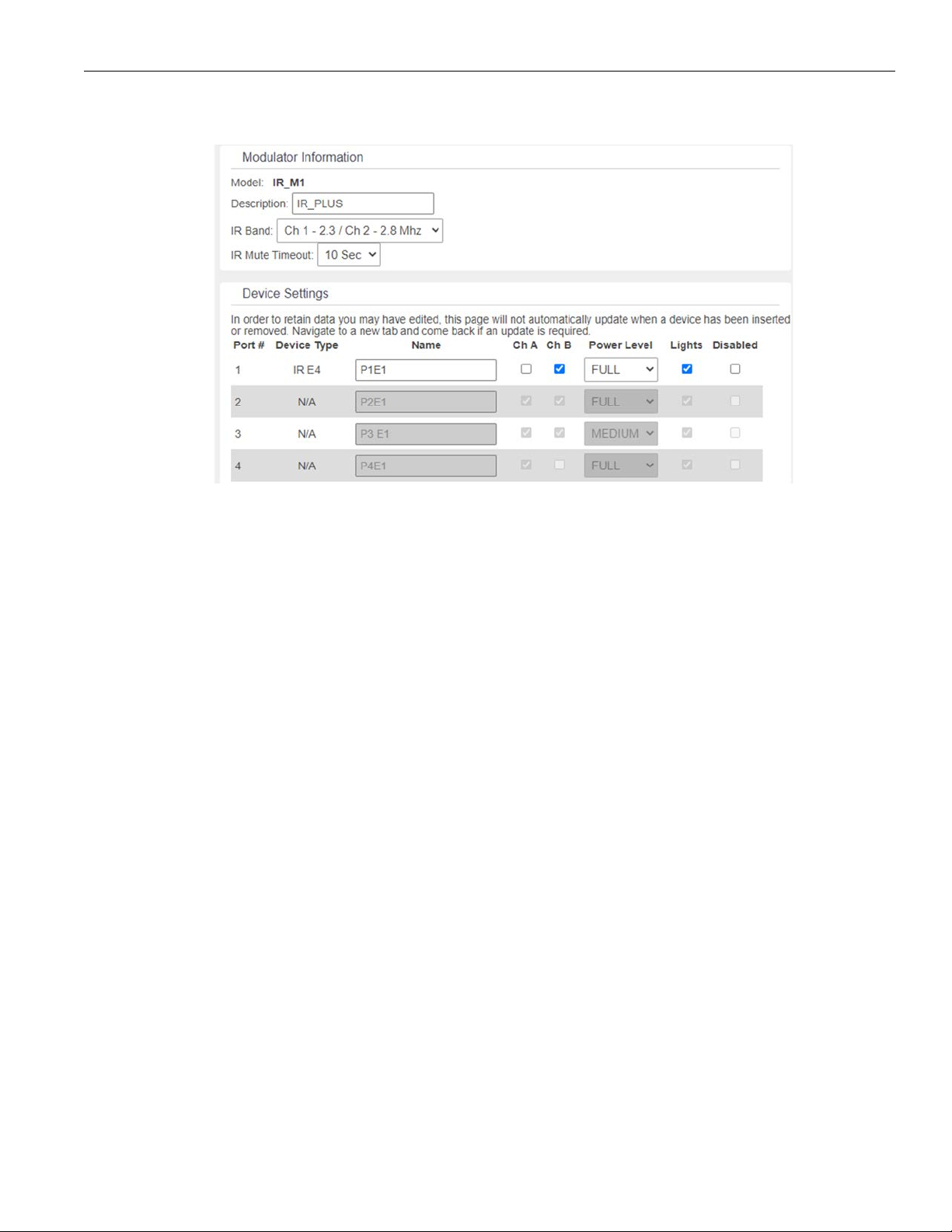
The Settings page is used to adjust settings for Williams Sound devices attached to the IR M1 as well as settings for the IR M1 itself.
Modulator Information
Control Center information is adjusted on the Settings page. These are settings specific to the IR M1. The IR M1 can be named
by editing the Description field. The IR band used for broadcasting is set here. The IR Mute timeout is how long the device waits
during silence to shut o the IR transmission and can be adjusted.
Device Settings
A list of ports and their stored device settings will be shown. Some fields will be editable if the device is connected, but data may
still be displayed if a device has been disconnected.
For each connected device, several settings can be adjusted. The name of the device can be set. Channel A and B can be
enabled and disabled, with Channel A enabled by default on each device. The power level used for the IR transmission can be set
to full power, or medium power (about half of the full power level). LED lights on the ports can be enabled or disabled, meaning
the lights will stay dark when operating. The connected device can be completely disabled or enabled; a disabled device will be
treated similarly to as if it was disconnected.
Connected, Disabled and Disconnected Devices and Settings Transfer
The settings screen will display the settings stored for the device usually connected to that port, even if it is not currently
physically connected via a CAT5e cable. These default settings are stored by the IR M1 and are saved for each Output to Emitter
port.
If a device is disconnected from that port, and a dierent device of the same type is connected (for example, an IR E4 is replaced
with a dierent IR E4), the stored settings will transfer automatically to that new devices. Connecting a device of a dierent type
will not transfer the settings.
Changes to the settings can only be made when a device is connected and enabled. Disabled or currently disconnected device's
settings cannot be edited. A disabled device can be re-enabled from the web interface if it is connected to the IR M1.
Disabled devices are not being provided power by the Control Center. This can be useful if it is dicult to physically unplug the
device.
NOTE: Do not cut any cable connected to a M1, regardless of if it's powered or not� (Disabling a device does not make it safe to cut
the wire�)
If a connected device is in an error state, it will be treated as if it is disabled until the error is corrected.
Devices cannot be enabled if their firmware is out-of-date. See "Administration Page" on page 21 for more information on
Firmware Updates.
17
Page 18
IR Plus Assistive Listening System
Audio Page
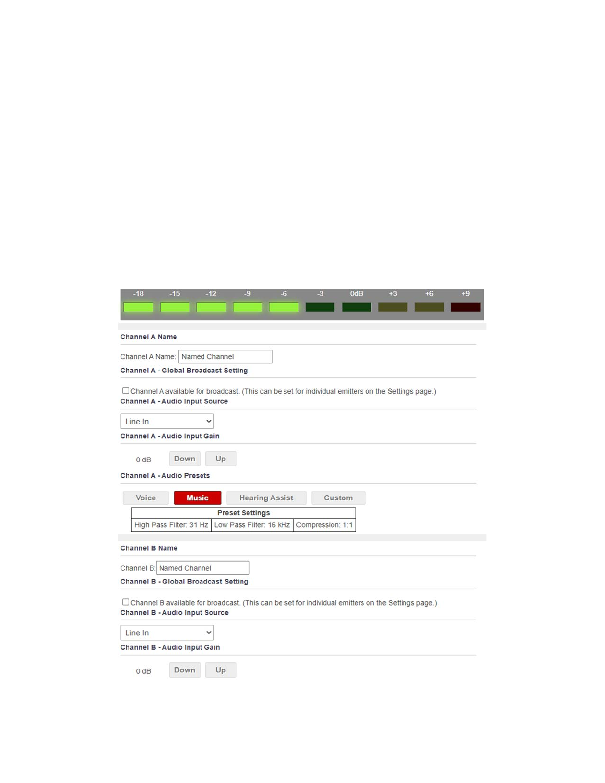
The Audio page displays all current audio settings. Most of the settings on the audio page are per audio channel. Settings for
channel A are edited separately from channel B.
Two VU meters are visible at the top of the page. The VU meters are for informational purposes only, and do not change any
settings.
Note: Network speed can aect the audio monitor updating and web page performance�
Each Audio channel can be globally enabled or disabled. This will prevent the channel from broadcasting over IR or Wi-Fi on any
emitter. To disable audio only on specific emitters instead of globally, use the disable feature on the Settings page.
Audio Input Gain adjusts the audio sensitivity of the IR M1. Use the Down and Up buttons to make changes to the gain.
The Audio Input Source selects the type of audio source that is connected to the selected channel.
Audio Presets adjust the sound to specific settings to improve the audio quality depending on if you are broadcasting audio that is
primarily voice, music, or for an audience requiring hearing assistance. The audio settings (including high pass filter, low pass filter,
and compression) can also be manually adjusted in the custom presets section.
See "Audio Settings" on page 13 for more details on adjusting any of these settings.
18
Page 19
IR Plus Assistive Listening System
Upload Image
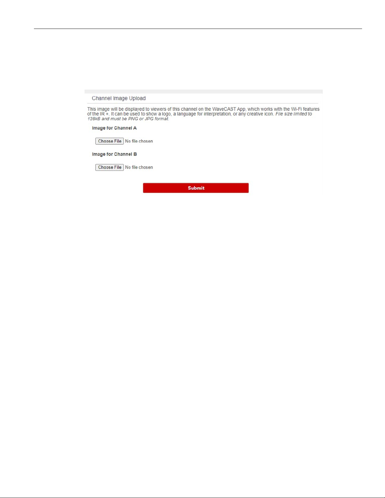
For each channel, an image can be uploaded that will display for any users listening using the WaveCAST app. This image can be
used to easily distinguish the content of your audio broadcast. The image must be under 128kB and be in PNG or JPG format.
The image can be replaced at any time. To completely remove the image, the device must be fully restored to factory defaults via
the front panel menu (see "Restoring Defaults" on page 23).
19
Page 20
IR Plus Assistive Listening System
Network Page
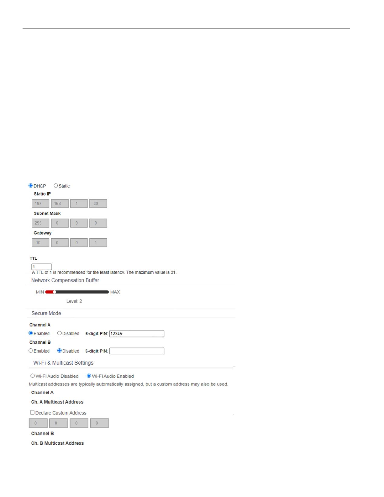
The Network Settings page aects settings specific to the server as a whole. The page displays network connectivity settings,
which are typically not needed after initial installation.
Changing a static IP address or subnet will not instantly take place. The changed IP address or subnet will only take aect once
the device is rebooted. The device will automatically reboot when submitting changes to the IP Address settings.
Note: If the IP address or subnet of the device was changed and the device is being rebooted, the website may not be available at
the same URL location� Take note of the network information before rebooting the device�
TTL can be modified if there is a need. The recommended setting for the least latency is 1, but it can be set up to 31. This setting
should not be adjusted without proper consideration for your system setup.
If audio is not streaming smoothly, adjusting the Network Compensation Buer setting will change the rate that the data is
streamed. Changing the rate can be helpful when a network connection is not sending the packets of audio data at a rate that
results in smooth audio streaming.
For each channel, the security settings and the multicast information of the channel can be adjusted.
Secure Mode can be enabled or disabled, and a 6-digit PIN number can be assigned. If enabled, users will need to use this PIN to
log on to the audio stream. Users attempting to listen to the stream without the PIN will be unable to do so.
A multicast address can be automatically assigned. If a specific multicast address is required, the device administrator can enter
the desired multicast address. There is no unicast mode of the IR +.
Additional networking information is described in "Network Configuration" on page 14.
20
Page 21
IR Plus Assistive Listening System
Administration Page
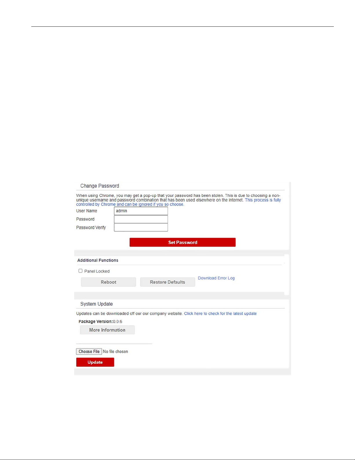
The Admin page displays administrative controls that can be used for remote site troubleshooting purposes.
The login username and password for the website can be set from this screen. If the username or password is ever forgotten, it
can be restored to its default value by restoring defaults via the front panel menu.
The panel lock will prevent the front panel on the device from being used, forcing all changes and information to be seen via the
web interface. This can also be enabled and disabled from the IR M1's front panel.
Restore Defaults will fully reset the device to factory settings. Network connection and login information will be reset, which may
make the website unavailable at the current IP address. See "Restoring Defaults" on page 23 for more information.
Updating or rebooting the device will make the website temporarily unavailable. While the device is restoring, a message warning
you to not power o the device will display on the OLED screen.
Firmware Updates
Firmware updates are performed from the Admin page. At the bottom of the page, upload the firmware file (provided by Williams
AV) and hit the update button. Your system will begin the update process from there, which will include a reboot. Firmware
updates are available on www.williamsav.com.
Updates will also push an update to all connected devices. If a device is not connected during the main update process, the IR M1
will update it when it is connected. If the update for the connected device is cancelled or incomplete, the device will be unable to
be used until the update is complete and will throw an error.
21
Page 22
IR Plus Assistive Listening System
Front Panel Interface
The front panel of the IR M1 can be used to change some system settings. For changing additional settings, the web interface will
need to be used (see "Web Control Interface" on page 15).
Main Menu
Some settings appear as you navigate the menu, and may not be visible when the menu is not being navigated.
Use the arrow buttons to highlight menu options. Left and right buttons navigate between fields, while the up and down buttons
adjust the field's value. To select an option from a menu, hold down the right arrow button. Menu items will typically time out after
10 seconds if no further button presses are made.
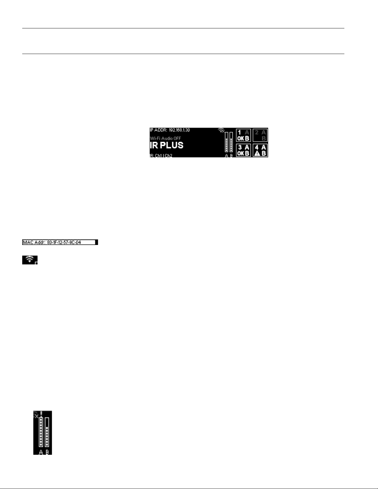
Channel VU Meters↓
Network Information/Wi-Fi Status → ← Port Information
System Name →
IR Output Channel →
The System Name of the IR M1 is displayed in large text on the front panel. This can be adjusted via the web interface (see
"Settings Page" on page 17).
The IR Output Channel is indicated in the lower left corner of main screen underneath the IR M1 name. The Output Channel will
list either CH 1 | CH 2 or CH 3 | CH 4. This information can be highlighted and adjusted using the up and down arrows. For an indepth explanation of this setting, see "IR Baseband Output" on page 14.
Network and Wi-Fi Audio Status
If an IP Address is displayed, a network connection is available and the web interface will be usable, regardless of if Wi-Fi audio is
enabled or not.
Selecting the IP Address and pressing the up or down arrows will toggle between displaying the IP
Address or the MAC Address. If an address is not available, dim dashes will appear instead.
The Wi-Fi icon indicates whether WaveCAST Wi-Fi Audio is enabled. If an X icon is over the network icon (as shown in the
full-screen image), Wi-Fi Audio is disabled. This icon does not indicate network availability.
The availability of WaveCAST Wi-Fi audio is also displayed in text above the IR M1's name. This text can be highlighted using the
right or left arrow buttons. Once highlighted, push the up or down arrow buttons to turn the Wi-Fi Audio on or o.
If Wi-Fi audio has been disabled, the text on the front panel will say so. Wi-Fi audio can be enabled by scrolling over the Wi-Fi
audio option and pressing the up arrow.
Port Information
The port information shows information for the devices connected under the Output to Emitter ports (see "Back Panel" on page
8). This includes which channels are active for that port, and the connected device's operating status, if available. Errors
on the device are indicated by the triangle icon, as seen in the main menu image for port 4. If the lower left corner of the box
is empty, there is no device connected, the connected device is disabled, or the connected device is not a Williams Sound
supported device.
NOTE: A device may have an empty lower left corner if the IR M1 has recently booted and is still gathering device information�
When a channel is disabled, it will show up in a darker grey on the main menu. In this picture, channel A is disabled on port 1.
Port 2 is entirely greyed out because no device is connected to that port. It may also be greyed out because the device has been
disabled via the web interface.
Port 3 is entirely bright, indicating the device is working properly and both channels are active.
To view additional port information, scroll over any of the four port's information on the main menu, then hold down the right arrow.
Channel VU Meter
The VU meter will work as long as there is audio actively playing, even when a channel is not currently broadcasting
anywhere. If the audio channel is not being broadcast, the VU meter will show up in grey instead of white.
22
Page 23
IR Plus Assistive Listening System
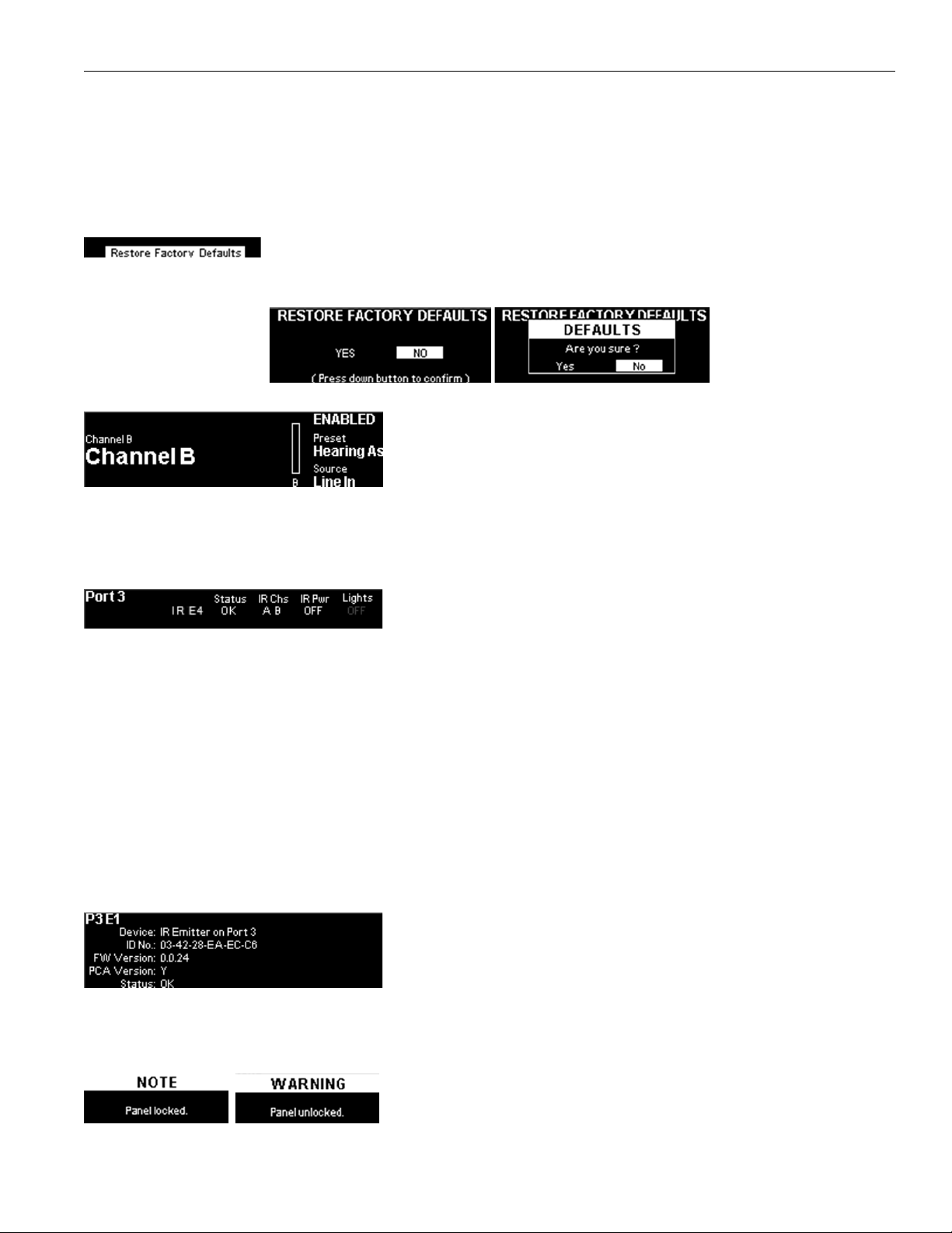
When a channel's audio is overloaded, a exclamation point will appear over that channels VU meter. Adjust the audio for that channel
to fix the issue. There is no low level audio indicator.
When channel A's VU meter is highlighted via the left or right arrow buttons, the gain for the channel will display and be adjustable
using the up and down arrows. Holding the left or right arrow button will display additional information on the Audio Channel Menu
screen.
Restoring Defaults
Restore Factory Defaults is a hidden option underneath the device name. Selecting this option will reset
the device to its factory settings, including network and login settings for the Web Control Interface. Two
confirmation prompts will appear before the settings are reset, including one to press down to confirm the restoration.
Audio Channel Menu
On the main menu, highlight an audio channel's VU meter and press and hold the
right arrow to view additional information.
Some audio channel settings can be edited. Use the up and down arrows to disable
or enable the channel, or adjust the input source.
The preset is visible on this screen, but can only be adjusted from the web interface. The VU meter is also visible on this screen,
but no additional settings are available.
To exit, keep pressing the right or left arrow buttons until the Exit option appears, then hold the right or left arrow to exit.
Port Information Screen
On the main menu, scroll over any of the four port's information box, then hold
down the right arrow. This will take you to the Port Information Screen.
The additional information displays the connected device's name, status, used
channels, power level and LED light status.
The device name is not in a labeled column. It is the first item in a row. In the picture, the device name is IR E4.
When a channel has been configured to broadcast on a particular port, it will be listed under IR Chs as A or B; otherwise, a line will
appear instead of a letter. If a channel is actively broadcasting, the letter will be white. If the channel is not broadcasting, the letter
will be grey. If an IR A4 is connected to the IR M1, channels A and B will be shown as white or as grey, depending on if any IR E4
connected to that A4 is actively broadcasting that channel.
If there is an error, the status ERR will be displayed. If a status of - - is displayed, the IR M1 is no longer communicating with the
attached device due to the device being disabled or some other non-error related reason.
From the Port Information Screen screen, highlight the device name by pressing the left or right arrow buttons, then hold the left or
right arrow buttons to see the Device Detail Page.
To exit, keep pressing the right or left arrow buttons until the Exit option appears, then hold the right or left arrow to exit.
Device Detail Page
On the Port Information Screen, highlight the device name by pressing the left or
right arrow buttons, then hold the left or right arrow buttons to see the Device
Detail Page.
The Device Detail page shows information about a specific device connected to
an Output to Emitter port. It includes a device description, ID number, firmware
versions and device status. This information may be useful when troubleshooting with TechBlue Technical Support Services (see
"Troubleshooting" on page 24).
Locking the Front Panel
To lock or unlock the front panel, hold both the left and right arrows for a few
seconds while on the main menu. A pop up will let you know the device is locked.
While locked, a pop up message that the device is locked will appear.
23
Page 24

IR Plus Assistive Listening System
WaveCAST App
The WaveCAST app allows listeners to hear the audio on their personal, Wi-Fi connected devices, such as a mobile phone. The
WaveCAST App can be downloaded from the Google Play Store for Android devices or the Apple App Store for iOS devices. The
WaveCAST App is compatible with the IR M1 and other Williams Sound Wi-Fi assistive listening systems.
Connect to Wi-Fi Network
The personal device will need to be connected to the same Wi-Fi network as the IR M1. Instructions for connecting each device to
the Wi-Fi network will dier; check the device manufacturer's instructions for how to set up a connection.
Connecting the App to the Channel
When the app is opened for the first time, a list of channels will be available. Tap on the channel
to hear it's audio.
The channel you are currently connected to will have a blue checkmark next to it.
If a list of channels does not appear, check that the personal device has Wi-Fi enabled. If it does,
troubleshoot the network connection of the IR M1 itself.
Listening via the App
Once connected to the channel, the audio should start playing automatically. The volume of the audio can be adjusted using the
slider in the middle of the screen, or the physical buttons on your device.
To mute the audio, tap the speaker icon. Tap it again to unmute the audio.
To switch channels, tap the icon on the bottom of the screen to display the list of channels again.
Note on Wi-Fi Assist/Smart Network Switching
The network connection the WaveCAST creates is not an internet connection. It creates a network connection to the audio stream
only.
Some phones expect network connections to provide internet access. When the phone cannot reach the internet, it may
automatically try to switch to a network connection with an internet connection. Sometimes, the phone determines that the best
internet connection is through a mobile data network.
This is not the desired behavior. The phone may automatically take the user o of the WaveCAST audio streaming network, and
onto a unrelated internet network connection. This will prevent the user from hearing the audio, and they may not realize their
phone switched networks.
Steps for disabling this feature will dier for every phone, but is typically found under the Wi-Fi or Mobile network settings. Look in
the manual for your phone for instructions on disabling this feature.
Troubleshooting
Follow the troubleshooting advice in this section to potentially resolve any issues. If the troubleshooting guide does not fix the
problem, please contact our Tech Blue design and support team at [email protected] or by calling +1-952-943-2252.
Website problems
The normal IR+ website is unavailable.
• If a webpage loads that only allows the installation a firmware update, the website stored on the IR M1 has been corrupted,
likely by a power outage. Install the firmware for your current version (or newer) of the IR M1 via the firmware update page to
restore the website. Firmware is available on www.williamsav.com.
• Check your network settings. The IP address is viewable on the front panel of the device. If the IP Address displays as dashes,
check the Ethernet connection to the IR M1.
Lost username or password
• Using the front panel menu, restore defaults. See "Restoring Defaults" on page 23.
24
Page 25

IR Plus Assistive Listening System
Website not behaving as expected
• The website will only work with a modern browser. Do not use the website with Internet Explorer or other outdated browsers.
• Do not use the website with Firefox; there are known communication issues with the website when using this browser.
• Try switching browsers. Google Chrome is our recommended browser. The website may have problems communicating with
the Control Center when using other browsers.
Audio problems
Noise or Distortion in the Audio
• Check to see if there is noise in the audio source. To find out, disconnect the audio cable. If the noise disappears your noise
problem is in the source. Correct or repair your audio source.
• Check for ground loops or noise on the input signal. If you are still having trouble, call your authorized Williams AV dealer or
representative.
• If audio sounds clipped or is too loud, try to turn down the gain for the channel. These issues may be more noticeable if the VU
meter for the channel is displaying the ! overload warning.
Noise in audio grows when program is silent
• Check the IR M1 Compression Ratio, which may be inappropriate for the type of program being transmitted. Try setting the
Compression Ratio to 1:1 (compression o).
Headphone Audio not adjusting for Compression or Other Changes
• The headphone audio is for listening to the audio source directly. No audio adjustments are fed through the headphone jack.
• Use an IR Receiver to hear adjusted audio. (See "Built in Emitters" on page 8)
Reception Diculties
No WaveCAST App Reception
• Ensure the listeners have the correct app open are listening on the same channel as the IR M1.
• Ensure the phone is on the correct Wi-Fi network.
• If using Wi-Fi Audio, ensure that Wi-Fi Audio is enabled on the IR M1. IR Audio is not detected by the app.
• Force close the app and reopen it.
Ch A or Ch B VU Meter does not show audio
• Make sure the IR M1 has power and is turned on.
• Make sure the audio input is connected properly.
• Make sure an active and adequate level audio signal is being sent to the IR M1 Control Center.
• Make sure your audio input is selected properly. If you're using a microphone and the channel is set for Line In, the audio
level will be too low.
• Try turning up the audio at the source, or using the gain adjustment on the IR M1. The IR M1 does not provide a low audio
level indication.
No Sound through Receivers
• Check to make sure the receiver is operating on the same frequency as the transmission.
• Make sure the front of the receiver is facing an emitter.
• If some of the receivers work but others don’t, check for bad batteries or earphones.
• If none of the receivers work, check to see if the power and audio input cables are connected to the IR M1. Verify that the VU
meters are showing audio levels.
• Check the Port Status via the front panel or web interface of the IR M1. Both displays can show if Ch A and/or B are active
and audio is transmitting. This indicates the problem is not with your IR transmission, but with the receivers, or installation.
• Make certain the emitter is not covered by objects which would block infrared light.
• Audio Gain or the audio level may not be loud enough.
Users must turn receiver volume controls up near maximum to get enough volume
• Ensure the emitters are pointed towards the audience and not blocked by anything.
• The audio gain control may be set incorrectly on the IR M1. Correct the Audio Gain control setting by adjusting it until the
sound level peaks near 0 dB.
• Some users may not be helped by this system. Severe hearing loss may require using the system with a T-coil and personal
hearing aid rather than headphones. Some phones and tablets have the ability to broadcast to a T-coil; research the phone
model to see if this is an option.
25
Page 26

IR Plus Assistive Listening System
Sound Through The Receivers Is Weak And Noisy.
• Listen to the audio signal through the Phones jack of the IR M1 Control Center. You can also hold a receiver in front of the
built-in emitters on the front of the IR M1 Control Center and listen to the audio signal. Hold the receiver within a few feet of
the IR M1.
• If the signal is weak and noisy here, check that the audio source selected is correct and that the VU meter is typically at 70%
of maximum level. Adjust the gain if necessary to calibrate VU levels.
• Increase the volume of the source or adjust the gain of the M1 if necessary to raise VU levels. If the signal sounds okay, you
may need to re-position the emitter(s).
NOTE: Make sure the powerline voltage does not fall below 94V, or system performance will be greatly reduced!
Buzz in other equipment
• This is likely caused by incorrect audio connections, a ground loop, or defective equipment. To remedy, use proper audio
wiring practice to make connections.
• Make certain the chassis is connected to the equipment cabinet rails. Buzz/hum in system may be experienced when the IR
M1 chassis is insuciently grounded. In this case, install a ground wire to the IR M1 chassis and terminate to a verified ground
source.
Device is not working over the hardwired Ethernet network
Note: If you have a network system administrator, please contact them first before attempting to troubleshoot the network yourself�
If you don’t have a system administrator, the following steps can be tried on a small, non-managed network�
In this situation you have to check the entire signal path between the control device (laptop or desktop computer) and the IR M1.
1. Check all of the wiring between the network the IR M1. Make sure every device in the signal path is plugged in, connected, and
powered on. Unplug and plug back in firmly all Ethernet cables in the path between the computer and the IR M1. If you find one
that was loose, plug it in and test the device connection again. If none are loose, you could also replace Ethernet cables.
Note: When checking connections, make sure the IR M1 Ethernet cable is plugged into one of the LAN ports on the router, not the
WAN port�
2. If no loose cables were found, try re-booting in this order
• the router
• the IR M1 (turn it o for 10 seconds then turn it back on)
Wait at least two full minutes for the IR M1 to re-establish itself on the network. Then try testing the connection again.
3. Open an internet browser on the computer. Type the IP address of the IR M1 into the address bar of the Internet browser.
4. Verify the connection by changing a setting on the IR M1 through the internet browser. If you can change settings and get
feedback on the web page (or verify the change on the front display of the IR M1), you are now connected to the IR M1.
5. If you can make changes to the IR M1 initially, but then lose that ability (get disconnected), you may have to look at network
issues such as IP address conflicts, power issues, or even settings in the router.
6. You can try restoring the IR M1 to factory settings. This will clear out any changes and allow you to start clean.
7. Try directly connecting the IR M1’s Ethernet cable to a PC to verify that the IR M1 and Ethernet cable are operational.
8. If you have tried all of these steps and still can’t connect, call Williams AV for additional troubleshooting help. Note that Williams
AV cannot help in all cases, as there are many variables within networks.
26
Page 27

IR Plus Assistive Listening System
Device is not working over Wi-Fi
Note: If you have a network system administrator, please contact them first before attempting to troubleshoot the network yourself�
If you don’t have a system administrator, the following steps can be tried on a small, non-managed network�
This situation is most often caused by the mobile device losing connection to the router when the Wi-Fi on the mobile device has
been turned o (or the Wi-Fi reception is unstable).
1. In order to perform these steps you will need the SSID (Wi-Fi network name) of the router, the router Wi-Fi connection
password, and the IP address of the IR M1. You can find the IP address on the front panel of the IR M1.
2. Make sure the IR M1 and router are both ON.
3. Make sure the Ethernet cable going to the IR M1 is plugged into one of the LAN ports on the router (not the WAN port).
4. Is the mobile device connected to the router? On the mobile device, go into the Wi-Fi Settings, and make sure Wi-Fi is turned
on or enabled. More than one router may show up in the list of possible connections, depending upon how many routers are
nearby. If you don’t see the router that is connected to the IR M1 in the list, make sure the router is on and broadcasting it’s
SSID.
5. If you see the desired router SSID in the list, connect to it by clicking on it. Usually there is a check mark or some other
indication of which router/SSID you are connected to. You may need to enter the Wi-Fi password/passkey to the router to
connect to it.
6. Once you have verified that you have connected the mobile device to the router, exit the Wi-Fi settings on the mobile device
(without shutting o the Wi-Fi) and open an internet browser. Type the IP address of the IR M1 into the address bar of the
Internet browser and hit the Enter key. You should see the IR M1 login web page come up.
7. Verify the connection by changing a setting on the IR M1 through the internet browser. If you can change settings and get
feedback on the web page (or verify the change on the front display of the IR M1), you are now connected to and controlling
the IR M1.
8. If there are still connection issues, try re-booting in this order
• the router
• the IR M1 (turn it o for 10 seconds then turn it back on)
Wait at least two full minutes for the IR M1 to re-establish itself on the network. Then try testing the connection again.
9. If you can make changes to the IR M1 initially, but then lose that ability (get disconnected), you may have to look at deeper
network issues such as IP address conflicts, power issues, or even settings in the router.
10. If there is interference, or low Wi-Fi signal on the mobile device, try moving the router to a better location.
11. Some mobile devices have known issues with certain routers. To fix this, you can investigate updating the operating system on
the mobile device. Try a dierent mobile device just to verify that ANY wireless device can connect. If you can get one device
connected, but not another, chances are the device that cannot connect has issues. A dierent brand/model of router may also
fix the problem with certain devices not connecting.
12. Try connecting to the IR M1 using Wi-Fi on a laptop, rather than a mobile device, to verify that the mobile device is/is not the
problem. If you can connect with a laptop, check the Wi-Fi settings on the mobile device and make sure Wi-Fi is turned On.
13. You can try restoring the IR M1 to factory settings. This will clear out any changes and allow you to start clean.
14. If you have tried all of these steps and still can’t connect, call Williams AV for additional troubleshooting help. Note that Williams
AV cannot help in all cases, as there are many variables within networks.
Checking Software Versions
Checking the software version will ensure that your system has the most up-to-date firmware possible. When the device is starting,
the firmware package version will be visible on the front panel.
Via the web interface, on the Administration page various version numbers for the IR M1 are visible under System Update -> More
information. This may be helpful when troubleshooting with TechBlue Technical Support Services.
27
Page 28

IR Plus Assistive Listening System
Specifications
IR M1
Dimensions: 19” (W) x 1.75” (H) x 8.2” (D)
(48.3 cm x 4.5 cm x 20.8 cm)
Weight: 5.2lb. (2.4 kg)
Color: Black
Rack Mount: Single Rack Unit
Power Supply: International Desktop Supply
Input: 36 W, 110-240 VAC 50-60 Hz
Output: +48VDC, 0.75A center-positive
Power Switch: Rocker switch with LED
Modulation: FM Wideband, +50kHz deviation, 50uS pre-emphasis
Carrier Frequency: Selectable, 2.3/2.8 or 3.3/3.8MHz
Signal to Noise Ratio: 67dB (typical)
Frequency Response: 40 to 16,000Hz, +1 dB, -3dB, electrical response
Total Harmonic
Distortion:
Audio Processor
Functions:
Auto Carrier Shut-O: Adjustable timer shuts o carrier when no audio is present. Adjustable through webpage.
Infrared Test LED: Dual IR LED for receiver testing, monitoring, and audio signal testing.
Audio Input: (2x) Combination 3-pin XLR, 1/4” (TRS) jack for balanced or unbalanced line level, or balanced or
Dante: Optional
Internal Test Tone: 400 Hz internal test tone selectable as audio input source for setup and diagnostics
Remote Configuration: Available through embedded website
Headphone Output: (2) 1/4" headphone jacks on front panel for monitoring CH A and CH B audio inputs
Emitter Output Jack: Four RJ-45 ports for CAT5e cables; provides +48VDC Power, RS-485 communication, and
Operating
requirements:
Approvals: CE, FCC, RoHS, RCM, WEEE, CB Scheme, ISED, VCCI
Warranty: 2 years on Control Center, 90 days on accessories
Less than 2%, electrical response
DSP based; Compression 1:1, 1.5:1, or 2:1; High-pass and low-pass filter frequency control
unbalanced microphone with selectable phantom power
Baseband signals for IR transmission.
0-50ºC ambient temperature, non-condensing, non-corrosive atmosphere
** Stresses above these ratings may cause permanent damage� Exposure for extended periods may degrade reliability�
IR E4
Dimensions: 7.5” (W) x 1.4” (H) x 3.6” (D)
(19.1 cm x 3.6 cm x 9.1 cm)
Weight: 0.8 lb (362 g)
Color: Black
Power: 48 VDC supplied by IR M1 via CAT 5e cable.
Coverage Area: Up to 18,000 square feet (1,670 sq. m) in single channel mode
Connectivity: +48VDC Power, RS-485 communication, and Baseband signals for IR transmission are all
provided via a single CAT5e cable inserted into an RJ-45 jack from the IR M1.
Operating
requirements:
Approvals: CE, FCC, RoHS, RCM, WEEE, CB Scheme, ISED, VCCI
Warranty: 2 years on Emitter; 90 days on accessories
28
0-50ºC ambient temperature, non-condensing, non-corrosive atmosphere
Page 29

IR Plus Assistive Listening System
IR A4
Dimensions: 7.6"W x 6.6"D x 1.1"H
(193mm x 168mm x 28mm)
Weight: 2.4 lb (1100g)
Color: Black
Power:
Connectivity:
Heat Dissipation: 1W
Max Cable Length:
Plenum Rating: The IR A4 is not rated for use in plenum spaces and will need to be installed in a plenum box for
Approvals: CE, FCC, RoHS, RCM, WEEE, CB Scheme, ISED, VCCI
Warranty: 2 years
NOTE: SPECIFICATIONS SUBJECT TO CHANGE WITHOUT NOTICE
48 VDC, 0.75A
+48VDC Power, RS-485 communication, and
via CAT5e cable(s) inserted into an RJ-45 jack from the IR M1 and out to the IR E4(s).
328 feet (100m)
use in such areas.
Baseband signals for IR transmission are all provided
Mounting Options
BKT 024 - Universal wall / ceiling mount (included)
MLB 003 - Linking bar for stacking emitters
STD 007 - Tabletop tripod stand
The IR E4 can be mounted on any camera tripod stand with a 1/4” - 20 threaded connector.
Optional Receivers
WIR RX22-4 Receiver
IR RX20 Receiver
29
Page 30

IR Plus Assistive Listening System
Regulatory Statements
FCC
FCC Compliance Statement
This equipment has been tested and found to comply with the limits for a Class B digital device, pursuant to Part 15 of the FCC
Rules.
These limits are designed to provide reasonable protection against harmful interference in a residential installation.
This device complies with Part 15 of the FCC Rules. Operation is subject to the following two conditions:
1. This device may not cause harmful interference, and
2. This device must accept any interference received, including interference that may cause undesired operation.
Caution: Any changes or modifications to the equipment not expressly approved by the party responsible for compliance could
void your authority to operate the equipment.
ISED
Innovation, Science and Economic Development Canada Statement
This equipment complies with IC RSS-102 radiation exposure limits set forth for an uncontrolled environment.
Operation is subject to the following two conditions:
1. this device may not cause harmful interference, and
2. this device must accept any interference received, including interference that may cause undesired operation
Cet équipement est conforme aux limites d’exposition de rayonnement d’IC RSS-102 déterminées pour un environnement non
contrôlé. Cet
Son utilisation est soumise aux deux conditions suivantes:
1. Cet appareil ne doit pas causer d’interférences et
2. il doit accepter toutes interférences reçues, y compris celles susceptibles d’avoir des eets indésirables sur son
fonctionnement.
VCCI
この装置は、クラスA機器です。この装置を住宅環境で使用すると電波妨害を引き起こすことがありま
す。この場合には使用者が適切な対策を講ずるよう要求されることがあります。 VCCI-A
This is a Class A equipment. Operation of this equipment in a residential environment could cause radio
interference. In such a case, the user may be required to take corrective actions. VCCI-A
30
Page 31

IR Plus Assistive Listening System
IR M1: 2-Year Warranty Statement
Williams Sound, a brand owned by Williams AV, products are engineered, designed, and manufactured under carefully controlled
conditions to provide you with many years of reliable service.
Williams AV warrants the IR M1 Control Center against defects in materials and workmanship under normal use and conditions for
the 2-years from the product from date of purchase.
This warranty is available to the original end purchaser of the product and can be transferred to subsequent purchasers of the
product.
Microphones, earphones, headphones, batteries, chargers, cables, carry cases, and most other accessory products carry a 90day warranty.
Williams AV has no control over the conditions under which this product is used. Williams AV, therefore, disclaims all warranties
not set forth above, both express and implied, with respect to the IR M1, including but not limited to, any implied warranty of
merchantability or fitness of use of such equipment including, without limitation, any warranty that the use of such equipment
for any purpose will comply with applicable laws and regulations. Williams AV shall not be liable to any person or entity for any
medical expenses or any direct, incidental or consequential damages caused by any use, defect, failure or malfunctioning of the
product, whether a claim for such damages is based upon warranty, contract, tort or otherwise, the sole remedy for any defect,
failure or malfunction of the products is replacement of the product. No person has any authority to bind Williams AV to any
representation or warranty with respect to the IR M1 System. Unauthorized repairs or modifications will void the warranty. This
warranty is void if damage occurred because of misuse, or if the product has been repaired or modified by anyone other than a
factory authorized service technician. Warranty does not cover normal wear and tear on the product or any other physical damage
unless the damage was the result of a manufacturing defect. Williams AV is not liable for consequential damages due to any
failure of equipment to perform as intended. Williams AV shall bear no responsibility or obligation with respect to the manner of
use of any equipment sold by it.
This warranty does not cover reimbursement for your costs of removing and transporting the product for warranty service
evaluation or installation of any replacement product provided under this warranty.
The exclusions and limitations set out above are not intended to, and should not be construed so as to contravene mandatory
provisions of applicable law. If any part or term of this Disclaimer of Warranty is held to be illegal, unenforceable, or in conflict with
applicable law by a court of competent jurisdiction, the validity of the remaining portions of this Disclaimer of Warranty shall not
be aected, and all rights and obligations shall be construed and enforced as if this warranty did not contain the particular part or
term held to be invalid. The terms of the warranty are governed by the laws of the State of Minnesota.
Prices and the specifications of the products are subject to change without notice. For Complete Warranty Statement go to: https://
williamsav.com/support/warranty-product-registration/
NOTICE: Williams AV products are NOT designed for use in extreme temperature, humidity or chemical environments. The
introduction of chemicals such as chlorine, salt water or human sweat into the product will cause damage to the circuitry. Damage
due to these causes is NOT covered under the Product Warranty.
If you experience diculty with your system, call Toll-Free for Customer Assistance
1-800-843-3544 (U.S.A.)
or +1 952 943 2252 (Outside the U.S.A.)
If it is necessary to return the system for service, your Customer Service Representative will give you a Return Authorization
Number (RA) and shipping instructions.
31
Page 32

IR Plus Assistive Listening System
IR E4: 2-Year Warranty Statement
Williams Sound, a brand owned by Williams AV, products are engineered, designed, and manufactured under carefully controlled
conditions to provide you with many years of reliable service.
Williams AV warrants the IR E4 emitter against defects in materials and workmanship under normal use and conditions for the
2-years from the product from date of purchase.
This warranty is available to the original end purchaser of the product and can be transferred to subsequent purchasers of the
product.
Microphones, earphones, headphones, batteries, chargers, cables, carry cases, and most other accessory products carry a 90day warranty.
Williams AV has no control over the conditions under which this product is used. Williams AV, therefore, disclaims all warranties
not set forth above, both express and implied, with respect to the IR E4, including but not limited to, any implied warranty of
merchantability or fitness of use of such equipment including, without limitation, any warranty that the use of such equipment
for any purpose will comply with applicable laws and regulations. Williams AV shall not be liable to any person or entity for any
medical expenses or any direct, incidental or consequential damages caused by any use, defect, failure or malfunctioning of the
product, whether a claim for such damages is based upon warranty, contract, tort or otherwise, the sole remedy for any defect,
failure or malfunction of the products is replacement of the product. No person has any authority to bind Williams AV to any
representation or warranty with respect to the IR E4. Unauthorized repairs or modifications will void the warranty. This warranty
is void if damage occurred because of misuse, or if the product has been repaired or modified by anyone other than a factory
authorized service technician. Warranty does not cover normal wear and tear on the product or any other physical damage unless
the damage was the result of a manufacturing defect. Williams AV is not liable for consequential damages due to any failure of
equipment to perform as intended. Williams AV shall bear no responsibility or obligation with respect to the manner of use of any
equipment sold by it.
This warranty does not cover reimbursement for your costs of removing and transporting the product for warranty service
evaluation or installation of any replacement product provided under this warranty.
The exclusions and limitations set out above are not intended to, and should not be construed so as to contravene mandatory
provisions of applicable law. If any part or term of this Disclaimer of Warranty is held to be illegal, unenforceable, or in conflict with
applicable law by a court of competent jurisdiction, the validity of the remaining portions of this Disclaimer of Warranty shall not
be aected, and all rights and obligations shall be construed and enforced as if this warranty did not contain the particular part or
term held to be invalid. The terms of the warranty are governed by the laws of the State of Minnesota.
Prices and the specifications of the products are subject to change without notice. For Complete Warranty Statement go to: https://
williamsav.com/support/warranty-product-registration/
NOTICE: Williams AV products are NOT designed for use in extreme temperature, humidity or chemical environments. The
introduction of chemicals such as chlorine, salt water or human sweat into the product will cause damage to the circuitry. Damage
due to these causes is NOT covered under the Product Warranty.
If you experience diculty with your system, call Toll-Free for Customer Assistance
1-800-843-3544 (U.S.A.)
or +1 952 943 2252 (Outside the U.S.A.)
If it is necessary to return the system for service, your Customer Service Representative will give you a Return Authorization
Number (RA) and shipping instructions.
32
Page 33

IR Plus Assistive Listening System
IR A4: 2-Year Warranty Statement
Williams Sound, a brand owned by Williams AV, products are engineered, designed, and manufactured under carefully controlled
conditions to provide you with many years of reliable service.
Williams AV warrants the IR A4 emitter against defects in materials and workmanship under normal use and conditions for the
2-years from the product from date of purchase.
This warranty is available to the original end purchaser of the product and can be transferred to subsequent purchasers of the
product.
Microphones, earphones, headphones, batteries, chargers, cables, carry cases, and most other accessory products carry a 90day warranty.
Williams AV has no control over the conditions under which this product is used. Williams AV, therefore, disclaims all warranties
not set forth above, both express and implied, with respect to the IR A4, including but not limited to, any implied warranty of
merchantability or fitness of use of such equipment including, without limitation, any warranty that the use of such equipment
for any purpose will comply with applicable laws and regulations. Williams AV shall not be liable to any person or entity for any
medical expenses or any direct, incidental or consequential damages caused by any use, defect, failure or malfunctioning of the
product, whether a claim for such damages is based upon warranty, contract, tort or otherwise, the sole remedy for any defect,
failure or malfunction of the products is replacement of the product. No person has any authority to bind Williams AV to any
representation or warranty with respect to the IR A4. Unauthorized repairs or modifications will void the warranty. This warranty
is void if damage occurred because of misuse, or if the product has been repaired or modified by anyone other than a factory
authorized service technician. Warranty does not cover normal wear and tear on the product or any other physical damage unless
the damage was the result of a manufacturing defect. Williams AV is not liable for consequential damages due to any failure of
equipment to perform as intended. Williams AV shall bear no responsibility or obligation with respect to the manner of use of any
equipment sold by it.
This warranty does not cover reimbursement for your costs of removing and transporting the product for warranty service
evaluation or installation of any replacement product provided under this warranty.
The exclusions and limitations set out above are not intended to, and should not be construed so as to contravene mandatory
provisions of applicable law. If any part or term of this Disclaimer of Warranty is held to be illegal, unenforceable, or in conflict with
applicable law by a court of competent jurisdiction, the validity of the remaining portions of this Disclaimer of Warranty shall not
be aected, and all rights and obligations shall be construed and enforced as if this warranty did not contain the particular part or
term held to be invalid. The terms of the warranty are governed by the laws of the State of Minnesota.
Prices and the specifications of the products are subject to change without notice. For Complete Warranty Statement go to: https://
williamsav.com/support/warranty-product-registration/
NOTICE: Williams AV products are NOT designed for use in extreme temperature, humidity or chemical environments. The
introduction of chemicals such as chlorine, salt water or human sweat into the product will cause damage to the circuitry. Damage
due to these causes is NOT covered under the Product Warranty.
If you experience diculty with your system, call Toll-Free for Customer Assistance
1-800-843-3544 (U.S.A.)
or +1 952 943 2252 (Outside the U.S.A.)
If it is necessary to return the system for service, your Customer Service Representative will give you a Return Authorization
Number (RA) and shipping instructions.
33
Page 34

[email protected] / www.williamsav.com
800-843-3544 / INTL: +1-952-943-2252
© 2020, Williams AV, LLC MAN 273B
 Loading...