

Page 1
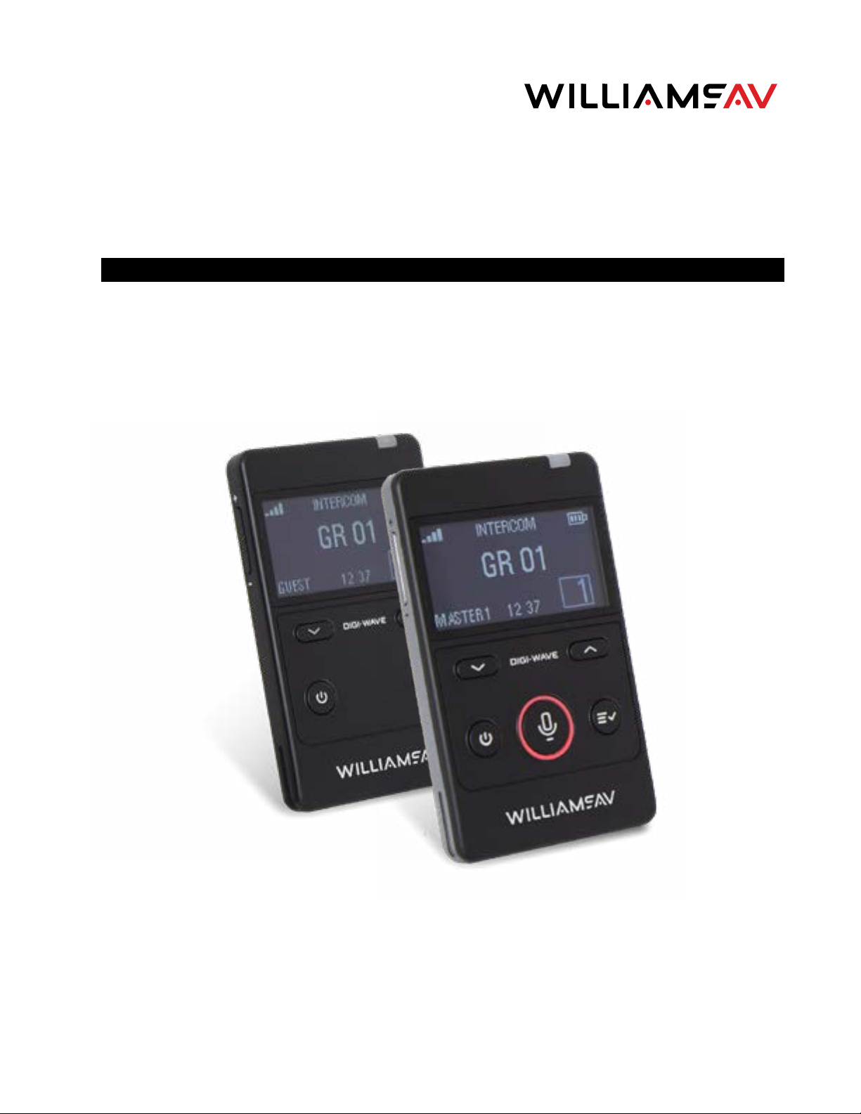
Digi-Wave® 400 Series
Digital Transceiver and Receiver
USER MANUAL
MAN 241J
Page 2
Digi-Wave 400 Series Digi-Wave 400 Series
Contents
Safety Warnings and Recycling Instructions
Safety Warnings and Recycling Instructions ....................................................................................................................................................3
System Overview ..................................................................................................................................................................................................................4
DLR 400 ALK Differences ................................................................................................................................................................................................4
DLT 400 Controls and Connectors ............................................................................................................................................................................5
DLR 400 RCH Controls and Connectors ...............................................................................................................................................................5
General Operation ...............................................................................................................................................................................................................6
Before Programming the Digi-Wave™ System ..............................................................................................................................................7
The Main Screen ..........................................................................................................................................................................................................9
Setting Up the Digi-Wave™ System ....................................................................................................................................................................... 11
Language ......................................................................................................................................................................................................................... 11
Initial Setup .................................................................................................................................................................................................................... 11
Changing Settings ............................................................................................................................................................................................................. 12
Basic Settings .............................................................................................................................................................................................................. 12
Advanced Settings ................................................................................................................................................................................................... 12
Interpretation Mode Features....................................................................................................................................................................................16
Floor and Interpreter ..............................................................................................................................................................................................16
Repeater Broadcast Mode .................................................................................................................................................................................. 16
Standard Interpretation Mode .........................................................................................................................................................................16
Bilingual Mode ............................................................................................................................................................................................................ 18
Relay Mode ................................................................................................................................................................................................................... 19
Court Mode ............................................................................................................................................................................................................................. 19
Saving and Replacing Profiles ...................................................................................................................................................................................21
Differences between DLT 400, DLT 300, DLT 100 2.0 & DLT 100..........................................................................................................21
HEARING SAFETY
CAUTION!
This product is designed to amplify sounds to a high volume level which could potentially cause hearing damage
if used improperly. To protect your hearing and the hearing of others:
1. Turn the volume down before putting on the earphone or headphone, and then adjust the volume to a
comfortable level,
2. Set the volume level at the minimum setting that you need to hear,
3. If you experience feedback (a squealing or howling sound), reduce the volume setting and move the
microphone away from the earphone or headphone.
4. Do not allow children or other unauthorized persons to have access to this product
MEDICAL DEVICE SAFETY
CAUTION!
1. Before using this product with an implantable or other medical device, consult your physician or the
manufacturer of your implantable or other medical device.
2. If you have a pacemaker or other medical device, make sure that you are using this product in accordance
with safety guidelines established by your physician or the implantable device manufacturer.
BATTERY SAFETY
CAUTION!
DLT 400 and DLR 400 RCH internal battery pack.
To reduce the risk of fire or burns, do not attempt to open, disassemble, or service the battery pack. Do not crush,
puncture, short contacts or dispose of in fire or water. Do not incinerate or expose to temperatures above 140ºF
(60ºC). Replace only with battery pack designated for this product: a rechargeable Lithium-polymer battery.
Recycle or dispose of properly.
Microphone/Headset Jack Difference .................................................................................................................................................................22
Differences Between Historical Digi-Wave DLTs ......................................................................................................................................... 22
Updating DLT 400 and DLR 400 RCH Firmware ......................................................................................................................................... 23
Advanced Interpretation Module ...........................................................................................................................................................................24
Interpretation Q&A Mode ...................................................................................................................................................................................24
24-Channel Interpretation Mode ...................................................................................................................................................................41
Control Function .......................................................................................................................................................................................................43
Channel Naming ...................................................................................................................................................................................................... 43
Channel Sub-Groups .............................................................................................................................................................................................46
Troubleshooting .................................................................................................................................................................................................................49
Specifications - DLT 400 Transceiver ...................................................................................................................................................................50
Specifications - DLT 400-AIM Transceiver ......................................................................................................................................................... 51
Specifications - DLR 400 RCH Receiver ............................................................................................................................................................. 52
Specifications - DLR 400 ALK Receiver .............................................................................................................................................................. 53
Regulatory Statements ................................................................................................................................................................................................. 53
2-Year Warranty...................................................................................................................................................................................................................56
CAUTION!
The lithium batteries used in the DLT 400 and DLR 400 RCH provide great performance and long life. But, like all
lithium batteries, they do have a limited number of charge/discharge cycles. Lithium batteries may experience
swelling if used beyond their expected life cycle (2 years). If you notice swelling of the battery, please discontinue
use and have the battery replaced. We recommend battery replacement after 2 years of use. For more information about replacing the battery, please visit our website at:
http://www.williamsav.com/digiwave-battery-replacement.
RECYCLING INSTRUCTIONS
Battery Safety and Disposal
Help Williams AV protect the environment! Please take time to dispose of your equipment properly. Please
do NOT dispose of batteries in the household trash. Please take the batteries to a retail or community
collection point for recycling.
Product Recycling:
Please do NOT dispose of your Williams AV equipment in the household trash. Please take the equipment to an
electronics recycling center or return the product to the factory for proper disposal.
32
Page 3
Digi-Wave 400 Series Digi-Wave 400 Series
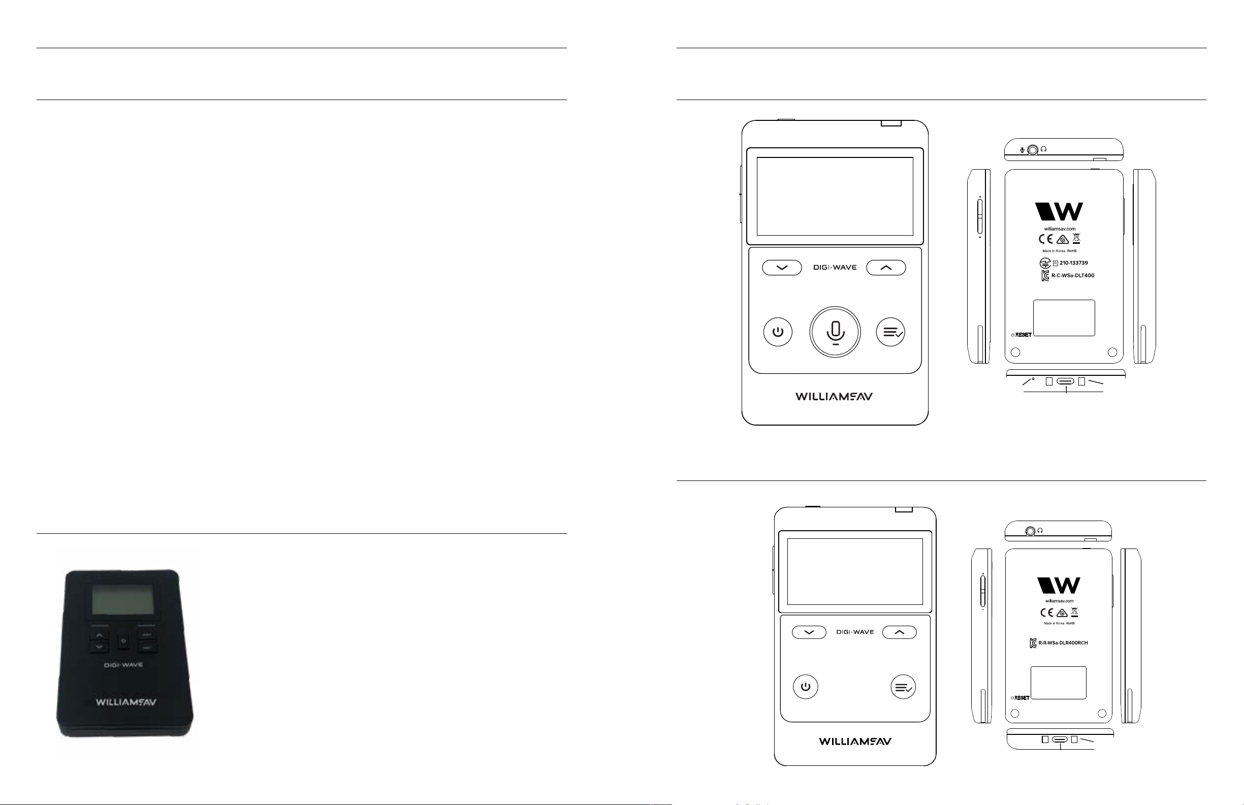
Menu/SelectPower Button
Up and Down Buttons
USB-C Charging Port
System Overview
The Digi-Wave communication system allows users to listen and talk to one another wirelessly in a variety
of scenarios. A Digi-Wave system consists of at least one transceiver (DLT 400) and various combinations of
transceivers and receivers (DLR 400).
The DLT 400 is a two-way transceiver, meaning that it can transmit and receive audio simultaneously.
The DLR 400 is a receiver only. Users of DLR 400 receivers can only hear what is being broadcast by DLT(s); they
cannot create any audio. There are two models of DLR: the DLR 400 ALK and the DLR 400 RCH. For information
on the differences, see “DLR 400 ALK Differences” on page 4.
For simplicity, throughout the rest of this manual, the DLT 400 may be referred to as a “DLT.” The DLR 400 RCH
and DLR 400 ALK as a “DLR” when the behavior of both devices is the same.
Combinations of one or more DLT’s and DLR’s can be used to facilitate different events, depending on what
needs to be spoken and what needs to be heard. Examples of scenarios will be covered here.
Typical Scenarios include:
• Guided Tours - with one or more tour guides (2-way), with audience participation (2-way), or without
audience participation (1-way)
• Language Interpretation - one or more interpreted languages transmitted to audience (1-way)
• Intercom - with up to six people able to speak simultaneously (2-way)
There are many more scenarios than are covered in this manual, however these would be variations on the ones
discussed here.
Backwards Compatibility
The Digi-Wave 400 Series is backward compatible with the 300 series with limited features.
It is not backward compatible with any earlier transceivers or receivers (DLT 100, DLT 100 2.0, DLR 50, DLR 60,
and DLR 60 2.0).
DLT 400 Controls and Connectors
Headphone and Microphone Jack
Volume
Adjust
Up and Down Buttons
Talk Button
Power Button
Menu/Select
Microphone
Internal
Charging LED
USB-C Charging Port
Charging Contacts
(For CHG 412)
The Technology
The Digi-Wave™ system is a digital spread-spectrum (DSS), simultaneous two-way wireless listening system
operating in the 2.4 GHz band. Due to it’s frequency-hopping algorithm, it avoids interference and is a very
secure method of communication. For a more detailed explanation of how Digi-Wave technology works, please
visit our website and download the “Digi-Wave™ Technology White Paper”.
DLR 400 ALK Differences
The DLR 400 ALK uses 2 AAA alkaline batteries rather than a rechargeable
battery like the DLR 400 RCH.
The AAA alkaline batteries can be inserted by removing the panel on the back
of the device and putting the batteries in place with the correct polarity. When
changing batteries, always change both batteries at the same time.
Help Williams AV protect the environment! Please recycle batteries once they
are drained.
Other Differences
The DLR 400 ALK allows you to select a group via the up and down arrows on
the front of the device. The volume may be adjusted using the vol buttons.
There is no menu system otherwise.
The battery and signal strength indicators on the screen work similarly to the
DLR 400 RCH, but are located on the far left of the screen.
When discussing DLR Receivers, this manual is usually referring to the DLR
400 RCH.
DLR 400 RCH Controls and Connectors
Headphone Jack
Charging LED
Volume
Adjust
Charging Contacts
(For CHG 412)
54
Page 4
Digi-Wave 400 Series Digi-Wave 400 Series
· Rapidly press the ^, ^, v, v buttons and then hold down the ^ and vol+ buttons (together) until the word
General Operation
Button Functions
Power Button
· Press and hold for power On/Off
· Press quickly to navigate back a step when using the menu.
“GROUP” begins flashing.
· Verify the Group Number displayed is the desired group. If not, change it with Vol+/Vol- buttons.
· Hold down the ^ and vol+ buttons (together).
· The unit is now unlocked.
DLR 400 RCH
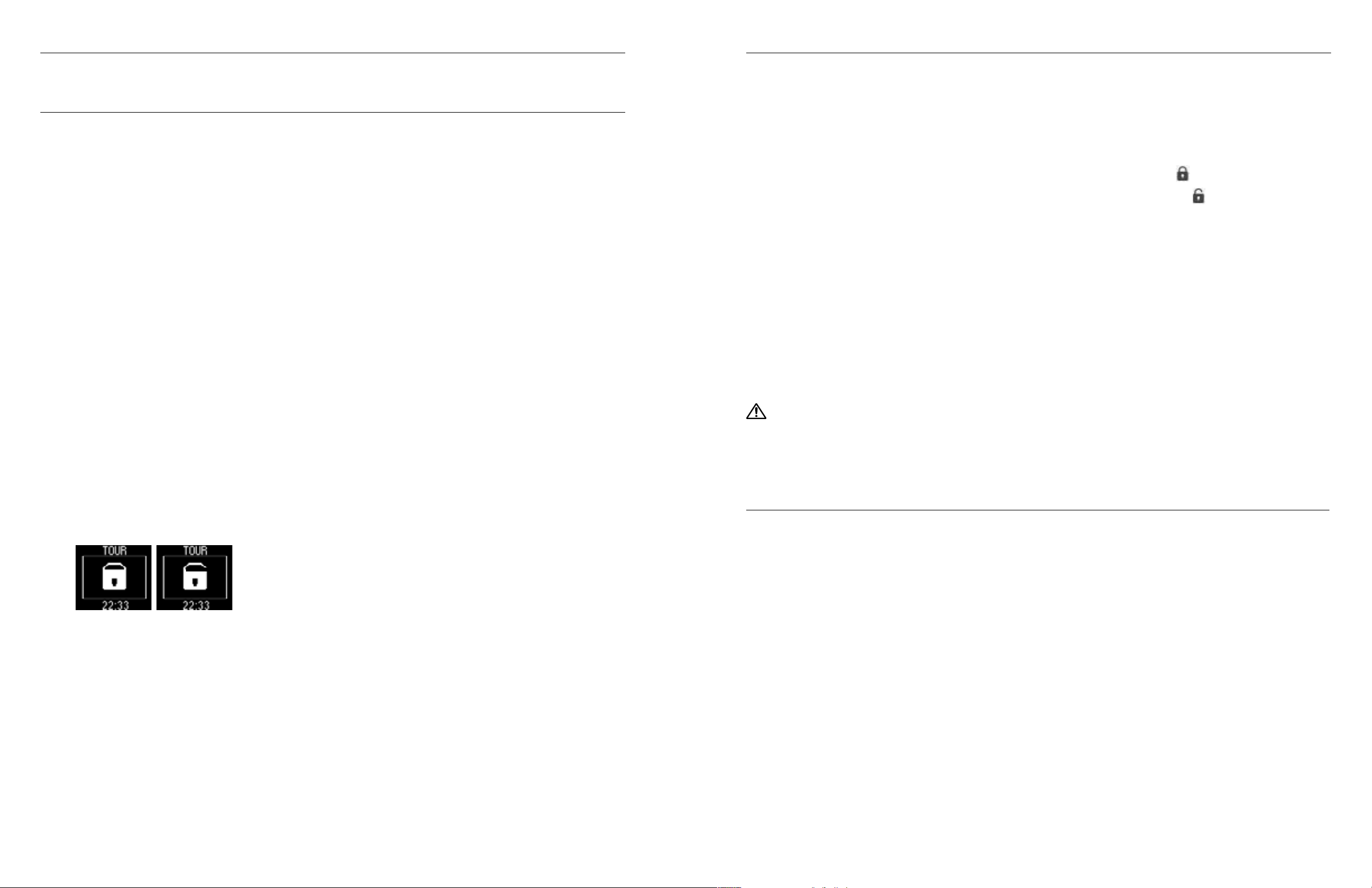
To lock: Hold the Vol+ (on the side) and Menu/Select buttons down together until appears on the screen.
To unlock: Hold the Vol+ (on the side) and Menu/Select buttons down together until
appears on the screen.
Volume Control Buttons (on side)
· Adjust the headset’s volume.
Talk Button
· The talk button will need to be used in order to talk or stop talking. There are two modes for the Talk button.
For more details, see “Talk Mode: Push-to-Talk and Push-n-Latch (DLT Master 2 and Guest Only)” on page
14.
· This button is only on the DLT transceivers.
· Devices with a Master 1 or Master 2 Speaking Priority can override any speaking Guests by holding down talk
button.
Menu/Select Button
· Press once while on the main screen to view additional Digi-Wave Information, such as firmware version.
· While on the main screen, hold the menu button down for a few seconds to enter the settings menu.
· While in the settings menu, press the menu button to select the highlighted option and move onto the next
step.
· While in the settings menu, hold the menu button to exit the menu.
Up and Down Buttons
· Navigate through menu items.
· Adjust settings
· In Bilingual Mode, toggle which language is spoken.
Battery Charging
Use the USB-C located on the bottom of DLT transceiver or the DLR 400 RCH Receiver, to charge the battery.
Charge by either using a USB-C cable or using an approved, compatible Williams AV charging station.
Full charging time is approximately 5hours. The charging LED flashes red while charging. The charging LED
will turn to a steady green light when the battery is charged.
NOTE: The DLR 400 ALK receiver uses alkaline batteries and is NOT rechargeable. Do not place these models
in a charging station.
Additional information
· The DLT 400 transceiver uses an internal rechargeable Lithium Polymer battery.
· The DLR 400 RCH receiver is rechargeable and uses a Lithium Polymer battery. Do not charge the DLR 400
ALK.
· Charge the battery at room temperature.
CAUTION!
All lithium batteries have a limited number of charge/discharge cycles. Lithium batteries may experience swelling if used beyond their expected life cycle (~2 years with casual usage. Heavy usage will reduce the life cycle). If
you notice swelling of the battery, please discontinue use and have the battery replaced. We recommend battery replacement after 2 years of use.
Locking the DLT Buttons and Screen
Basic Lock
Lock enables the Administrator to prevent unauthorized changes to the system set-up by preventing the user
from accessing the menu and using the up and down arrow buttons.
NOTE: Each DLT has to be locked and unlocked individually.
· To enable or disable the lock, hold down the volume up button and hold the menu button at the same time
for 2 seconds. The lock icon will appear
· When lock is enabled, the menu system will have most features unavailable with a lock icon displayed next
to it.
Locking/unlocking DLR Buttons and Screen
Locking prevents the user from changing Group/Channel. While locked, Volume up/down and Power on/off can
still be changed.
DLR 400 ALK
To lock:
· Hold the ^ and Vol+ buttons down together until the word “GROUP” begins flashing.
· Rapidly press the ^, ^, v, v buttons and “SL” will be displayed.
· The unit is now locked.
To unlock:
Before Programming the Digi-Wave™ System
Depending upon the mode chosen, up to six people can talk in a group at any given time. The Master 1 will
have first priority, Master 2 has second priority and Guest units have third priority. When two or more people
are talking in a group, the participants can hear their voices with the DLT transceivers or DLR receivers, but only
those with a DLT transceiver have a microphone and can speak.
Modes
The Digi-Wave 400 system has been designed for ease and flexibility. Many of the settings are automatically
configured for common use cases. These use cases are Tour Mode, Intercom Mode, Hearing Assistance Mode
and Interpretation Mode.
While the modes are named by their most common usage, select the mode that fits your personal use case
best. The mode is a just starting point; advanced settings can be adjusted to fit your situation.
Modes
Tour
Tour mode is best suited when one or two people are leading a large group. The group can be configured to
only listen to the leader(s) of the group, such as on a museum tour. Alternatively, this mode allows people with a
transceiver to speak, which may be useful for tours through noisy areas where hearing may be difficult, such as
factory tours.
Intercom
Intercom mode is appropriate when a group of up to 6 people all need to talk to and hear one another. It may
be used behind the stage to manage a large theater production, or for a security team at a club.
Hearing Assistance
76
Page 5

Digi-Wave 400 Series Digi-Wave 400 Series
Hearing Assistance mode is appropriate when using the device to amplify spoken communication between
users. The Tone Control in Hearing Assistance mode is automatically elevated, allowing the user to hear more
clearly. Users with transceivers can be allowed to speak, which may be useful in a classroom setting.
Interpretation
Interpretation mode is best suited when dealing with multiple, simultaneous audio feeds. In normal
interpretation mode, an interpreter may be translating a speech given in Spanish into English, a group of
interpreters may be translating a speech in English into several languages. Up to 14 languages and the floor
may be broadcast on the Digi-Wave system at one time.
Court
Court mode allows toggling between secured groups, without letting the Guest unit on an unused or incorrect
Group. A Guest unit can access up to four pre-selected groups, but nothing else. Although this mode is named
Court Mode, this mode can be used whenever a limitation to group selection is needed.
Interpretation Mode: Broadcast Type
When in Interpretation Mode, you will be required to select a broadcast type. The broadcast type helps
determine which channel the DLT transceiver will broadcast on.
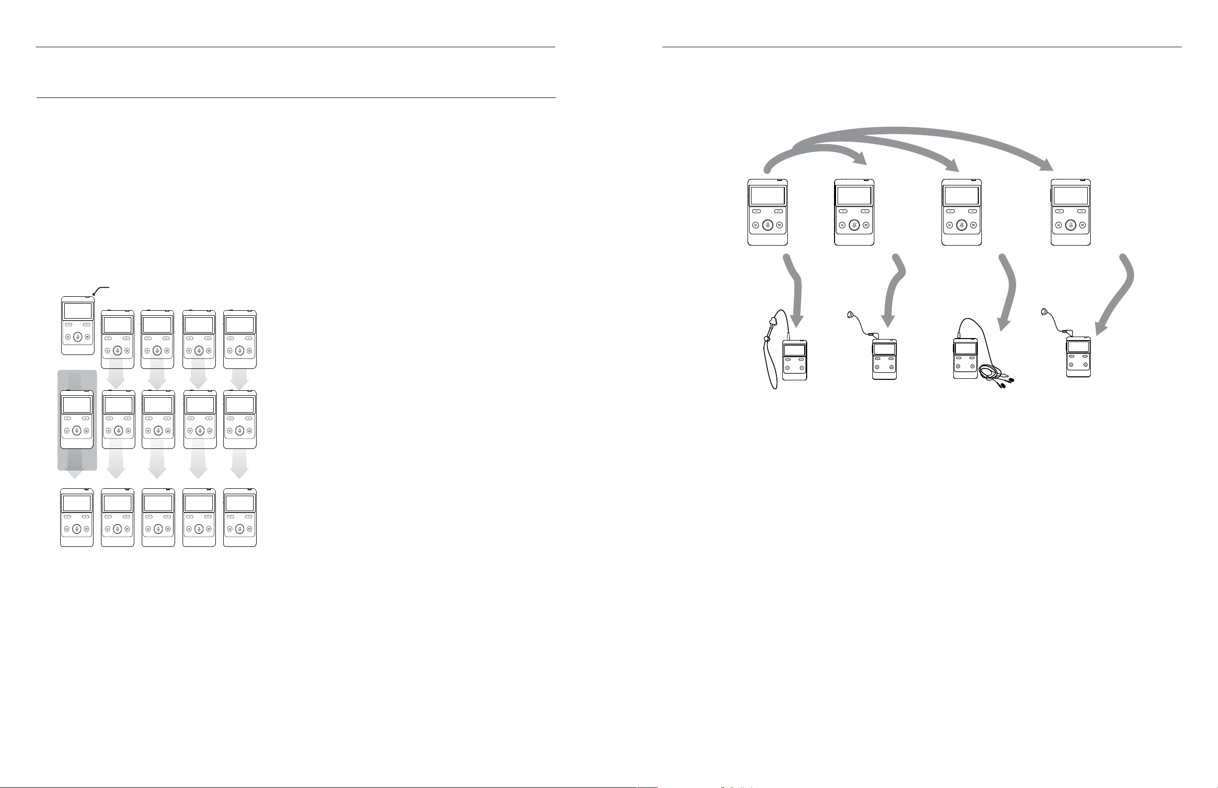
Floor will broadcast on channel 0. This is intended to be the main audio for the event that is being interpreted.
Interpreter will broadcast on channel 1 - 14 depending on what is available. Each channel is able to be used by a
dedicated interpreter. All interpreter units can hear the Floor on channel 0, and transmit the Interpreter’s voice
on channels 1 - 14. At any time, by changing channels, anyone can listen to the Floor on Ch. 0 or any Interpreter
on channels 1 - 14. The interpretation is broadcast 1-way in up to 14 languages.
Repeater is used to extend the range of the Digi-Wave 400 system by up to 50%. The repeater will broadcast on
one channel, depending on which channel(s) needs to be extended. This mode does not require a person to be
speaking or listening to the transceiver.
For more information on additional features of Interpretation Mode, see “Interpretation Mode Features” on page
16.
Speaking Priority
There are 3 levels of priority.
• Master 1 has first priority, and also sets up a majority of the settings for the Digi-Wave system. There
can be only one Master 1 unit per group.
• Master 2 has second priority when speaking, but does not declare any settings for the Digi-Wave
system, only for their personal device. This is not available in Interpretation mode.
• Guest units have third priority, and can only declare settings for their personal devices.
The Master 1 and Master 2 have the ability to lock out other talkers by holding down the Talk button for three
seconds. All system Talk LEDs will continuously flash while other participants are locked out of the Talk feature.
The Master 1 can override anyone else talking within the group. Master 2 has talking priority over Guests.
The Master 1 or Master 2 must have their talk button deactivated to allow the Guest units to talk. When 2-6
people are talking in a group, the participants can hear their voices in the DLT transceivers or DLR receivers.
DLR receivers can only listen, as they do not have a microphone or talk button.
If a Master 1 unit leaves the conversation, the other devices in the group cannot continue the conversation
without them. A Master 1 must be present for the Digi-Wave system to be used.
Channels are used in Interpretation mode. Users configure their device to listen to a certain channel based on
what they need to hear. For instance, in Interpretation mode, their may be a channel per language. Users will
listen to the channel for the language they speak, and not hear the audio for languages they do not understand.
In a theatre with two showrooms, the Digi-Wave system may have a group for each theater. Each group may
have up to 15 channels of audio in use. Each user will need to be assigned the correct group for the theater they
are sitting in, as well as the correct channel for the appropriate audio.
Addresses
Addresses are unique numbers given to each Digi-Wave transceiver in a set up. Typically, addresses will be
automatically assigned but in some use cases, manual assignment may be necessary. If manually assigning
addresses, make sure each address is unique; addresses between 0 and 1023 can be selected. Each of the 1024
addresses is available per group.
DLR receivers do not have addresses.
Selecting Group(s) and Channel(s)
Each set of people who want to talk and/or listen to each other must be in the same group. Up to 4 Groups can
operate simultaneously within range of each other. Up to 15 channels can be used simultaneously.
Group numbers and channels are selected via the settings menu. Pressing the up or down button will allow you
to manually select the group or channel number.
Profiles
Configurations of settings can be saved to a Profile to be easily reloaded later. A profile may be created on any
device and loaded later. Profiles are useful when Digi-Wave devices are used in multiple ways, such as being
used for both Tours and Hearing Assistance.
General Rules of Operation
The following rules must be followed. Failure to adhere to these rules will result in unpredictable,
unsupported operation.
• There must be only one Master 1 per group.
• Master 2 is optional, and there can only be one per group.
• Any other DLT 400 units must be a Guest unit.
• Each DLT transceiver must have its own address and the address cannot be duplicated within a group.
• Each group must be assigned its own group number. Williams AV recommends a maximum of four
groups using the system simultaneously within the same area to prevent interference.
• When using four simultaneous groups, group numbers must be sequential. i.e. 11, 12, 13, 14. Any numbers
0-1023 can be used (only 0-99 if DLR 360 or DLT 400 ALK receivers are being used).
The Main Screen
Groups and Channels
Depending on the Mode you select, you will primarily be working with Groups or Channels. Both settings
determine who hears the audio, and are very similar in concept.
Groups are used in every mode. A group is a selection of people communicating with one another. For instance,
there may be one tour group for a basic tour and another tour group for a VIP tour. Both these groups may be
in the same area, but their audio will not overlap since they are in different groups.
Display Settings
The mode will be displayed at the top of the screen, between the signal strength indicator and the battery level
indicator.
Depending on your setting selections, the clock, the channel or the group will be displayed in the center of
the screen. Channel or Group is determined by your mode. A large or small clock is determined by the Master 1
settings.
To change any of these settings, hold down the menu button. For instructions on configuring the Digi-Wave
98
Page 6

Digi-Wave 400 Series Digi-Wave 400 Series
system, see “Basic Settings” on page 12.
Signal Strength Indicator
When a Master 1 is available on the group or channel, the signal strength indicator on DLR Receivers and
Guests will indicate how strong the signal is.
When a Master 1 is not available OR while the Master 1 is changing settings that may affect other devices, the
icon will disappear. Once the Master 1 has been set up, the DLR Receiver and other DLT transceivers should
rejoin the group or channel automatically (with some exceptions, such as a Security PIN being set).
Attendee Checking
The number of DLT transceivers currently talking will be displayed in the bottom right corner box. It does not
count DLR Receivers because they do not have a talk button.
Priority Indicator
A label indicating Master 1, Master 2 or Guest will appear on the lower left of the screen on the main screen.
If the label is blinking, the device has not had its settings configured. Enter the menu system to begin
configuring the device.
Setting Up the Digi-Wave™ System
Settings of the Digi-Wave system should be selected based on how the system will be used. A Master 1 device
will declare a majority of the settings and pass these settings to devices that connect with it. Since the Master
1 automatically sets most settings, there is little to be set up on Guest devices for basic usage of the Digi-Wave
system.
For more information on terminology and a general system overview, see “Before Programming the DigiWave™ System” on page 7.
Language
The Digi-Wave menu is available in multiple languages. Select the language you desire for set up.
Initial Setup
When a DLR Receiver or a DLT transceiver is first started, some settings will need to be
selected before the device can be used. There are three ways to load settings on a
Digi-Wave device:
New Settings
To start from the very beginning with your Digi-Wave settings, select New Settings. This will start you at the
beginning of the set-up process where you can set Basic Settings (see “Basic Settings” on page 12).
Load Profile
To load an existing profile on the device, select this option and then select the profile to load. You may either
load a profile as it is, or adjust the settings once it is loaded (see “Basic Settings” on page 12).
Join Group
If a Master 1 is already leading a Group or Channel, Digi-Wave 400 transceivers and receivers can automatically
search for the group and join it. The list of available groups will be in the order the device detects them, which
may not be in numerical order.
The group or channel number could also be manually entered from this screen. Settings will be loaded from
the Master 1 device, once a connection is established.
If a group or channel is locked by a PIN, the device will prompt for the PIN at this time. The device will be unable
to join the group or channel without this PIN.
For interpretation mode, a Master device should not use this feature. They will be unable to select the
channel they desire. Please configure the device using the normal setup menu. Guest units can use the Join
Group function normally.
When using this feature to join a group, Addresses will be automatically set. If you need manual addresses, the
DLT 400 will need to be set up using a profile or through setting up New Settings.
If the group should not be able to be automatically joined, this feature can be disabled by the Master 1 device for
specific groups. See “Allow Join Group” on page 15 for more information.
1110
Page 7
Digi-Wave 400 Series Digi-Wave 400 Series
TOUR MEMBER 4 (THE 5th UNIT) CAN LISTEN TO THE GROUP -OR- CAN TALK BY PUSHING TALK BUTTON AND KNOCKING TOUR MEMBER 1 OFF
Changing Settings
If settings need to be adjusted later, the menu system can be reentered at any time by holding down the menu
button for a few seconds. From there, settings can be edited by selecting New Settings. You may also load a
profile or join a group or channel.
The menu system can be exited at any time by holding the menu button. Any uncustomized settings will be set
to their default.
To go back to a previous setting while in setup mode, press the Power button.
Basic Settings
Always start setting the Digi-Wave settings with the DLT transceiver that will be the Master 1. Other devices can
gather their settings from the Master 1 device to ease setup. DLR Receivers and other DLT transceivers that are
not Master 1 may still need their settings adjusted, but they should still be set up after the Master 1.
1. Select a Mode. This determines what other settings may be available. See “Modes” on page 7 for more
details on the various modes.
2. Select Speaking Priority. If this is the first DLT transceiver you are setting up, you will want to select Master 1.
Typically, all other units will be Guest priority. See “Speaking Priority” on page 8 for more details on the
various speaking priorities.
3. Select the group number. Holding down the up or down button will seek for available groups/channels.
Pressing the up or down button will allow you to manually select the group or channel number. For more
information on groups, see “Groups and Channels” on page 8.
4. If in Interpretation Mode, set the Broadcast Type (see “Advanced Settings” on page 12).
5. The Master 1 can select a handful of options that will affect the main display on other devices:
• Select whether to display clock or hide it entirely.
• Select the clocks location, if displayed.
• Select whether the clock is a 24-hour or 12-hour clock.
• Set Master 1 manual address. (Guests and other device can set the address under Advanced Settings.)
Automatic address selection is recommended unless there is a need to override the address.
6. Enter Advanced Settings (See “Advanced Settings” on page 12) if more customization is needed,
otherwise the device is ready to be used.
Advanced Settings
Advanced Settings are usually available regardless of the mode selected, but some Advanced Settings may be
missing from certain modes, or with certain configurations.
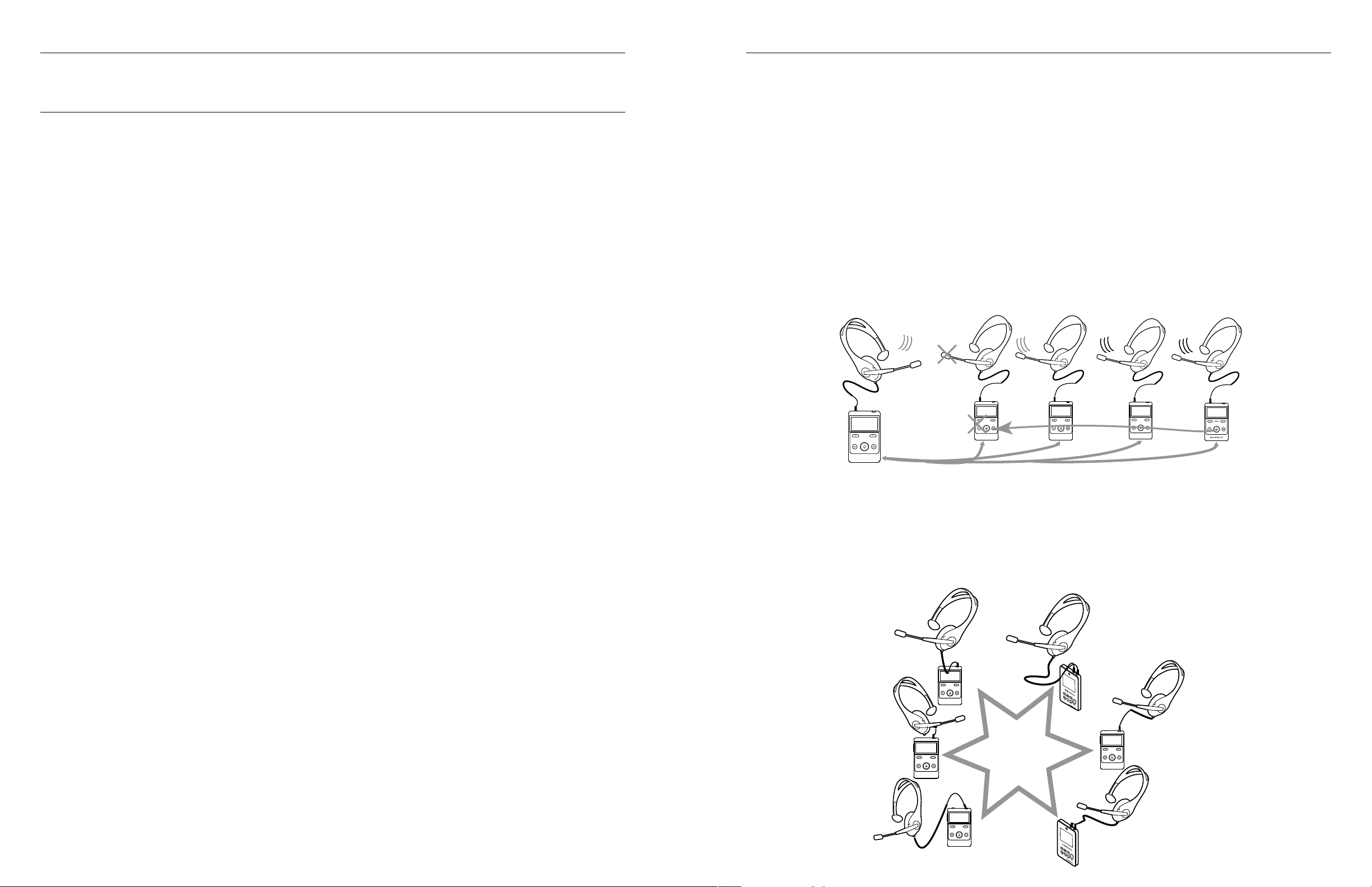
Example - Tour System
The system has been configured so that up to four people can have open microphones and be talking at the
same time. One DLT is set up as a Master 1 unit for the tour guide. Each tour member has a DLT transceiver set up
as a Guest unit.
When a 5th person desires to speak, they push their talk button. This deactivates the talk button of the first Guest
that turned their microphone on. This First-In-First-Out speaking priority continues each time a member pushes
their talk button who is not a part of the speaking group.
If the group speaking needs the 5th person to be able to speak, they can adjust their device settings to allow 5
speakers.
The Master 1 or Master 2 Tour Guide has the ability to take control of the discussion by overriding Guest units, if
needed. This is accomplished by pushing-and-holding their talk button down for a few seconds which mutes all
Guest unit microphones. When overriding, the talk button will blink red.
A second Tour Guide may be added as a Master 2 unit, which takes priority over Guest units. Master 1 and 2
units have two-way communication capability; they can talk/listen simultaneously to one another.
TOUR GUIDE
TOUR GUIDE MODE
SUPPORTS UP TO
4 OPEN MICROPHONES
-BUT- ONLY 4 PEOPLE CAN TALK AT THE SAME TIME (4 OPEN MiCROPHONES MAX)
TOUR MEMBER 1
TOUR MEMBER 2
TOUR MEMBER 3
TOUR MEMBER 4
Example - Intercom
One DLT transceiver is set up as a Master 1 unit. All other DLT transceivers are programmed as a Guest unit. Up
to six people can have open microphones and be talking at the same time. When a 7th person desires to speak,
they push their talk button. This deactivates the talk button of the first Guest that turned their mic on. This
First-In-First-Out order continues each time a member pushes their Talk button who is not a part of the
speaking group.
Number of Microphones (DLT 400 only)
In modes where multiple speakers are available, the number of speakers at one time can be limited. The
maximum number of speakers is 6, the minimum is 2 when this option is available. The number of microphones
is not limited by the selected mode (except for in Interpretation Mode, which assumes one speaker per
channel). Users with DLR Receivers do not have microphones or talk buttons and cannot be speakers in any
circumstance.
Only 4 speakers using DLT 300 transceivers are allowed. 6 speakers can still be in the group, but the 5th and 6th
speakers must be using DLT 400 transceivers.
DLT 400
programmed as
Master 1
DLT 400
programmed
as Guest
INTERCOM FEATURE
SUPPORTS UP TO SIX
SIMULTANEOUS TALKERS.
DLT 400
programmed as
Guest
DLT 300
programmed
as Guest
DLT 300
programmed as
Guest
DLT 400
programmed as
Guest
1312
Page 8

Digi-Wave 400 Series Digi-Wave 400 Series
Talk Mode: Push-to-Talk and Push-n-Latch (DLT Master 2 and Guest
Only)
On a DLT transceiver, the Master 2 or Guest Talk Mode can be changed to Push and Latch or Push to Talk.
Master 1 DLT transceivers are always set to Push-N-Latch mode. This feature is not available on a DLR Receiver
as it does not have a microphone or talk button.
In Push-n-Latch mode, when the talk button is pressed and released, it stays in talk mode until the talk button
is pressed and released again.
In Push-to-Talk mode (the default mode), the talk button must be held down while speaking, and when
released, it shuts off.
Tone Control
The default for tone control is 5, unless in Hearing Assistance mode, where the default is 9.
Using the up and down arrow buttons, adjust the tone up or down to your preference. The number range
indicates:
• 1 = Most bass response
• 5 = Flat
• 9 = Most treble response
Side Tone Adjustment
This gives the user the ability to change the volume of their own voice as heard in the headset (side tone). This
feature is only available on the DLT transceiver.
Use the up and down arrow buttons to choose between off (0 dB), low (-12 dB), or high (-6 dB).
Encryption PIN:
When a group or channel has been set up with a Encryption PIN, master and
guest transceivers and DLR 400 receivers without this Encryption PIN entered
cannot listen in on the group. This may be desirable in private or high security-level
functions. The PIN cannot be used with DLR 400 ALK units.
The same four digit code must be programmed into all of the Digi-Wave devices
in the group. If a different secure code has been entered, participants cannot re-enter the group without reentering the correct secure code. The only time the Encryption PIN is displayed is when it is being entered. As
the PIN is being entered, individual numbers will be replaced by the * symbol.
We recommend using a unique PIN to your group. Using PIN 0000 or other easily entered or guessed PIN will not be as effective as a unique pin.
To set the PIN:
1. Select whether or not the connection requires a PIN. If yes, you will be prompted to enter the desired PIN.
2. Choose a 4 digit numerical code; i.e. 4297. You must use the same code on each device in the group.
3. Using the up and down arrows, enter first digit of the code (0 – 9).
4. Press the menu/select button to move to the second digit. Enter the next digit and continue until all four
digits have been entered.
When setting up the other transceivers or receivers for this group or channel, enter the same code into those
devices.
When the Encryption PIN is set, a key icon will show on the main screen under the signal strength indicator.
Microphone Gain, Line Input Gain and Line Output Gain
Gain can be used to increase the volume of the microphone or line input sound. Line input is connected via a
USB-C connector.
Use the up and down arrows to adjust the gain to a suitable level. The default value for the microphone gain is
33. The default value for the line input gain is 5. The default value for line output gain is 0, but can be adjusted to
+4dB.
Note: For setting up an input line interface, please contact TechBlue Technical Support.
Display Clock
The clock can be displayed in several formats on the main screen. It can be shut Off, displayed Big in the center
of the screen, or displayed Small near the bottom of the screen (default behavior).
The group or channel will be displayed at the bottom of the screen in small font if the clock is set to display big.
The group or channel will be displayed in the center of the screen if the clock is set to off or small.
Manual Group and Address
If the Group or Address needs to be adjusted, it can be set here. This may be necessary if needed to be
backwards compatible with the DLT 300 or DLR 360 from the previous generation.
Encryption
Extra security can be added to the transmitted signal via encryption. The “300 Compatible” 87-bit encryption
is default. This level of encryption is backwards compatible with the DLT 300 from the previous generation. The
DLR 360 cannot work with encrypted signals.
128 + 87-bit Encryption adds AES-128 encryption on top of the 87-bit encryption. This adds an additional layer
of security, but is not backwards compatible and may only be used with Digi-Wave 400 devices. This method
requires an Encryption PIN.
To remove an Encryption PIN when using 300 Compatible mode (Pins are required in 128+87 mode):
1. Go through the menu system until you are prompted if you would like to use a PIN code.
2. Select “NO PIN CODE.” The existing PIN will be removed.
Allow Join Group
The Master 1 can prevent other devices from seeing the group as available to join. Disabling Join Group will
prevent available groups from being listed under the Join Group menu. Devices will have to be manually set to
the correct group or channel.
See “Join Group” on page 11 for more details on the Join Group feature.
Factory Reset
If the Digi-Wave device is not behaving correctly, or otherwise needs to be reset, a factory reset option is
available. This is the last item in the Advanced Settings menu. If the device is reset, all changes selected before
this reset will be lost.
The factory reset can also be done manually. A hole is on the back of the device. The hole covers a switch that
can only be reached with a paper clip or other thin material. Pressing the button with the paper clip while the
device is on will display a prompt on the screen asking to perform a factory reset. Select Yes to reset the device.
1514
Page 9
Digi-Wave 400 Series Digi-Wave 400 Series
Main speaker (floor)
CH 0
CH 1 CH 2 CH 3
...
CH 14
GUEST
CH 0
CH 1 CH 2 CH 3
...
CH 14
MASTER
GUEST REPEATERS
CH 0
CH 1 CH 2 CH 3
...
CH 14
DLT TRANSCEIVER OR DLR RECEIVER
CH 2
CH 3
CH 1
CH 0
INTERPRETER
Listening on Ch. 0
Speaking on Ch. 1
(French)
INTERPRETER
Listening on Ch. 0
Speaking on Ch. 2
(Spanish)
INTERPRETER
Listening on Ch. 0
Speaking on Ch. 3
(German)
THE AUDIENCE LISTENS TO
THE CHANNEL OF THEIR
LANGUAGE
Listening
Ch. 3
German
Listening
Ch. 0
English
Listening
Ch. 1
French
ALL INTERPRETERS
ARE LISTENING TO
THE MAIN SPEAKER
ON CHANNEL 0
EACH INTERPRETER
SPEAKS/TRANSMITS
ON A DIFFERENT
CHANNEL
Listening
Ch. 2
Spanish
MAIN SPEAKER/
FLOOR
Speaking on Ch. 0
(English)
Interpretation Mode Features
Interpretation Mode has several features not available in other Digi-Wave modes.
During setup, you will be prompted to select a broadcast mode and select an additional interpretation mode.
The available options for broadcast mode are Floor, Interpreter and Repeater. The available options are for the
additional interpretation mode are Standard, Bilingual and Relay.
Floor and Interpreter
The floor is the main speaker or audio of the event. In a lecture, this is the person standing at the podium.
Interpreters translate the audio from the floor into another language. There can only be one floor in a Digi-Wave
system, but there can be up to 14 interpreters.
The floor will always broadcast their audio on channel 0. Interpreters
can broadcast their audio on channels 1-14. Interpreters can listen to channel 0 as they interpret in standard
interpretation mode.
language requires their own DLT transceiver and interpreter. The audience member then listens to the channel
for their specific language.
Note: In previous Digi-Wave versions, this was known as Simultaneous Interpretation Mode.
Repeater Broadcast Mode
Repeater mode can be entered by selecting it as the Broadcast Type during setup.
An additional DLT 400 can be set-up as a repeater to increase the range of each channel.
When repeater mode is used, the Repeater is configured as the Master 1, and all units sync to this Master
Repeater. The floor unit should be configured as a guest.
There can only be one repeater per channel and one of the repeaters must be a Master unit. In basic scenarios,
it is best to set the Repeater on Channel 1 since most connecting devices can easily access this channel.
Standard Interpretation Mode
Standard interpretation mode allows for each DLT transceiver to listen to the floor (the main speaker) on
channel 0 and broadcast out in one interpreted language on a channel (1-14). Each additional channel or
1716
Page 10
Digi-Wave 400 Series Digi-Wave 400 Series
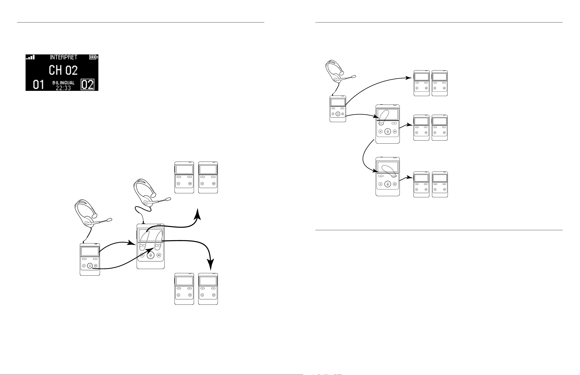
Bilingual Mode
Bilingual mode allows the interpreter to quickly switch their output
channel between Ch. 1 or Ch. 2, depending on which language the
audience needs to hear.
This mode eliminates the need for the interpreter to physically switch
between 2 DLT transceivers programmed to fixed channels. The
interpreter can easily switch between which channel is being broadcast by
using the up or down arrow under each channel listed.
For example, the Floor changes from a Japanese speaker to an English speaker. When the Floor is speaking
Japanese, the bilingual interpreter selects Ch. 1 as the output channel and interprets Japanese to English to
the English audience. When the Floor changes to a English speaker, the interpreter selects Ch. 2 as the output
channel and interprets English to Japanese to the Japanese audience.
The DLT transceiver in Bilingual Mode always listens to channel 0, regardless if channel 1 or 2 is chosen as the
transmission channel. Only one DLT transceiver can be programmed to transmit on channels 1 and 2.
The bilingual interpretation mode may be utilized within a larger system. For example, one interpreter can use
the bilingual mode on channel 1 and 2, while others have the normal mode on other channels. It does not work
with Relay Mode.
CH 1CH 1
Interpreter
Presenter
(Floor)
Ch 1
English
Audience
Relay Mode
Presenter
(Floor)
Japanese
CH 0
Listening to the Floor
Japanese
Interpreter #1
Ch. 1 (Relay)
Japanese-English
FL 1
Listening to the Floor
(”FL” selected)
Interpreter #2
Ch. 2
English-Spanish
Listening to the Relay
(”re” selected)
re 2
Note: Bilingual Interpretation is unavailable in Relay Mode.
English
Spanish
Ch 0
Japanese
Audience
CH 0CH 0
Ch 1
English
Audience
CH 1 CH 1
Ch 2
Spanish
Audience
CH 2 CH 2
Relay Mode allows the interpreter to quickly switch
between listening to the Floor on Channel 0 or the
Relay on Channel 1.
For example, the floor is speaking Japanese. The
Japanese audience can listen to the Floor on Ch.
0. Interpreter 1 pushes the down button to hear
the floor, and interprets Japanese to English to the
audience listening on Ch. 1. Interpreter 2 speaks
English and Spanish, and cannot translate from
the floor as they do not speak Japanese; they need
to listen to Interpreter 1’s translation as a relay.
Interpreter 2 listens to the relay (Interpreter 1) by
pushing the up button and interprets English to
Spanish to the audience listening on Ch. 2.
Channel 1 is automatically the Relay channel.
Channel 1 will automatically listen to Channel 0,
just as in Standard Interpretation Mode. The DLT
transceiver transmitting on Channel 1 cannot switch
and listening to Channel 1, and the floor cannot
listen to channel 1. Interpreters on other channels
(2-14) are able to switch which channel they are
listening to.
Only one DLT can be programmed to transmit
on each channel. All interpreter units must be
programmed in the Interpretation with Relay Mode,
and cannot be combined with units programmed
in other modes.
Presenter speaks Japanese,
Interpret in English
CH 0
When the
On CH 1
1 2
Ch 1 English
Ch 2 Japanese
When the
Presenter speaks English
Interpret in Japanese
On CH 2.
Ch 2
Japanese
Audience
Court Mode
Court mode may require a firmware update to version 1.2.0 or higher to be available on your Digi-Wave
devices.
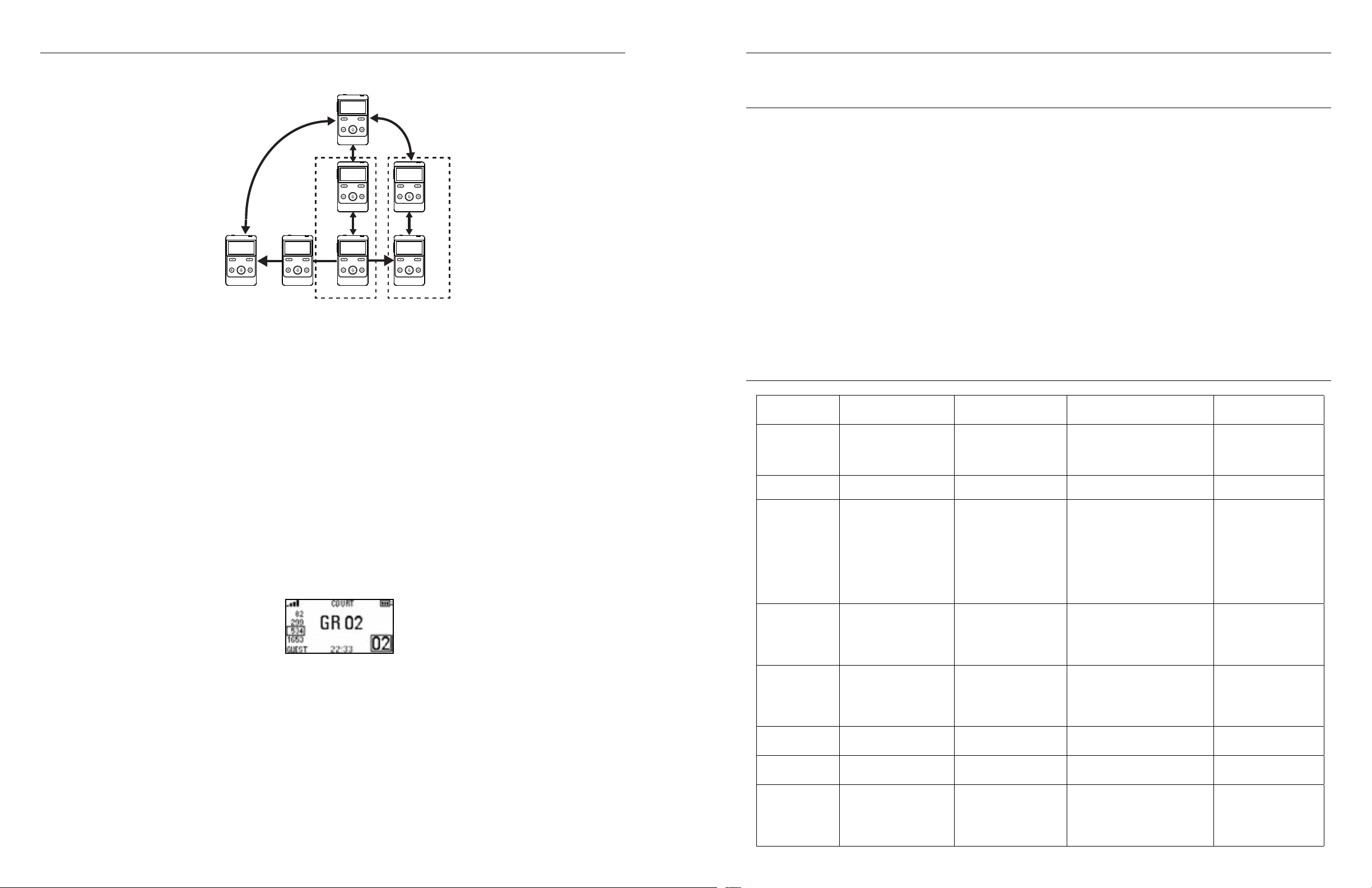
Court mode is used to limit users to specific groups. When not in court mode, a guest Digi-Wave unit can
change their group to any group. In Court Mode, the guest unit can only access up to four pre-selected groups.
Limiting the access to groups may be useful in situations requiring privacy and security, such as in a court. For
example, a lawyer may need to privately consult with their client on Group 12, and may also need to listen to the
judge on Group 10. To prevent the lawyer from accidentally broadcasting private case information on any other
CH 2CH 2
Group, the lawyer would be limited to only accessing Groups 10 and 12.
PIN codes can be assigned to a Group to further secure access to a group. Court mode has the added benefit of
quickly toggling between groups, even if they require a PIN code, without letting the Guest unit end up on an
unused or incorrect Group.
Although this mode is named Court Mode, this mode can be used whenever a limitation to group selection is
needed.
1918
Page 11
Digi-Wave 400 Series Digi-Wave 400 Series
INTERPRETER
GROUPS
10/11/12
10
MASTER
REPORTER
GROUPS
10
JUDGECOURT
11
MASTER
GROUPS
10/11
MASTER
GROUPS
10/12
COUNCILCOUNCIL
12
CLIENTCLIENT
Device Availability
Court Mode is only available for DLT 400 transceivers and DLR 400 RCH receivers. It is not available for DLR 400
ALK units or for backwards compatibility with the Digi-Wave 300 Series.
For older Digi-Wave 400 series units, a firmware update may be required to use Court Mode.
Group Selection
A Master unit can only be in one group and cannot toggle between groups. Like most other modes, the Master
unit will be programmed with the settings for one specific group.
Guest units can access up to four groups. The Guest will be able to add up to four groups. If a PIN code has been
set up for the group, the Guest will be required to enter it when they add the group. PIN codes are only available
in with Encrypted signal transmission.
Both the Master and any Guest devices must be set to either encrypted or unencrypted signal transmission.
Once the setting for Court Mode have been saved on a Guest device, any Group previously accessible by the
unit will be erased from the device. All groups the Guest unit should be allowed access to will need to be
entered at once. A single group cannot be added or removed later.
Toggling Between Groups
Once setup is complete, the Guest unit can use the Up and Down buttons to toggle between the list of groups
on the left hand side of the screen.
The Guest indicator will flash until the group is joined. If a device seems unable to join a group, check the PIN
code.
Locking the Device
To prevent Guest units from accessing the setup menu, using Basic Lock is recommended. Basic lock can be
activated by holding the volume up button and menu button at the same time for a few seconds.
Guest units can still edit some personal auto settings by repeatedly pressing (not holding) the menu button.
These settings include viewing the System Information, and Adjusting Mic Gain, Side tone, and Tone. Volume is
adjustable using the volume up and volume down buttons.
Microphone Mute
Court mode requires Push-n-Latch mode. Push-to-Talk mode is not available in Court mode. To mute your
microphone, press the Talk button so the red light around the Talk button is no longer on.
Holding down the talk button will not mute all speakers in court mode.
Saving and Replacing Profiles
After settings have been configured, you will have the option to save your settings as a profile, or replace an
existing profile. This is only available if Advanced Settings have been adjusted.
If you choose to not save your profile, the device will still use the settings but they cannot be loaded again if the
settings are later changed.
Saving Profiles
After selecting your settings, you can select a numbered profile where you can save your settings. Five profiles
are available.
Profiles that are being used have a disc icon next to them. Profiles can be overwritten if desired.
Select the profile name to use to save the settings to the profile. If the profile is already in use, confirm that you
are replacing an existing profile.
Loading Profiles
For information on loading profiles, see “Load Profile” on page 11.
Differences between DLT 400, DLT 300, DLT 100 2.0 & DLT 100
Function/
Description
Lock Mode
Voting function Not Available Not Available Not Available Available
GRP button /
ABS button
^ button / yes
“ch+” button
v button / no
ch-button
Listen only (1way mode)
Speaker only (2way mode)
Group Number /
Clock function
DLT 400 DLT 300 DLT 100 2.0 DLT 100
Most settings
unavailable when lock
set. Lock icon next to
unavailable settings.
Not Available
Labelled ^
Navigates menu system
Channel/Group up
Labelled ^
Navigates menu system
Channel/Group down
Not Available
Not Available
Can switch positions.
One may be displayed
in the center of the
screen, the other small
near the bottom.
With settings locked,
can ONLY adjust
Power, Volume, Talk
Labelled “GRP”
1-way mode: not
functional
2-way mode: used to
enable easy group
change with pushand-hold of this
button
Labelled ^
1-way mode: Channel
up
2-way mode: Group up
Labelled v
1-way mode: Channel
down
2-way mode: Group
down
Available
Available
Icon GROUP and
Group Number
Displayed in place of
Clock on Main Screen
With settings locked, can
ONLY adjust Power, Volume,
Talk
Labelled “GRP”
1-way mode: not functional
2-way mode: used to enable
easy group change with pushand-hold of this button
Labelled ^
1-way mode: Channel up
2-way mode: Group up
Labelled v
1-way mode: Channel down
2-way mode: Group down
Available on F-8 firmware
Not available on F-7 firmware
Available on F-8 firmware
Not available on F-7 firmware
Icon GROUP and Group
Number Displayed in place of
Clock on Main Screen
With settings locked,
can adjust Power,
Volume, Talk, Tone,
Mic level, and Group
Labelled “ABS”
1-way mode: not
functional
2-way mode: On
Master, used to
enable voting; on
Master 2 or Guest,
used to “Abstain”
when voting
Labelled yes
1-way mode: Channel
up
2-way mode: Group
up
Labelled “no”
1-way mode: Channel
down
2-way mode: Group
down
Available
Available
Clock Enabled on
Main Screen and
during Master 1 Setup
2120
Page 12
Digi-Wave 400 Series Digi-Wave 400 Series
Function/
Description
Talk Timer
function
Push-to-Talk and
Push-and-latch
functions
Microphone
Gain Max Level
Side Tone
Adjustment
Dock detected/
Mic Disable
Auto shutoff
timing for Guest
Units
Line Input or
Output Level
Adjust
Compatible with
Digi-Wave Dock
DLT 400 DLT 300 DLT 100 2.0 DLT 100
Not Available; Group
Not available.
Available on Guest
units only
53 53 53 63
St: Off, low = -12 dB, high
= -6 dB
Available with adapter
5 min.
Available in Menu
System
Available with adapter Yes Yes No
number displayed in
place of Talk Timer on
Main Screen
Available on Guest
units only
St: 0=off, St: 1=-6 dB, St:
2=-12 dB
Available; The DLT 100
2.0 is compatible with
a dock.
5 min. (Same as DLR
360)
Available with
push-and-hold of “^”
button; eight levels L:0
through L:7
Not Available; Group number
displayed in place of Talk
Timer on Main Screen
Available on Guest units only Not Available
St: 0=off, St: 1=-6 dB, St: 2=-12
dB
Available; The DLT 100 2.0 is
compatible with a dock.
5 min. (Same as DLR 60 2.0) 2 min.
Available with push-and-hold
of “^” button; eight levels L:0
through L:7
Available
Not Available
Not available. The DLT
100 is not compatible
with a dock.
Not Available
Description
Mic Gain Max Level 53 53 53 63
Digi-Wave Dock compatible With Adapter √ √
Up to 2 Active Mics √
Up to 4 Active Mics √ Tour Guide Mode
Up to 6 Active Mics √ Intercom Mode
DLT 400
DLT 300 DLT 100 2.0 DLT 100
not limited to 2 in tour
mode
√ √
Updating DLT 400 and DLR 400 RCH Firmware
The Digi-Wave® system should ship with the latest firmware; however, over time systems may need to be
updated. A Digi-Wave® Downloader program will need to be installed onto a computer in order to load the
firmware onto the Digi-Wave® device. The Downloader is a separate software download from the Digi-Wave®
firmware itself. Please contact Tech Blue at [email protected] to receive the Downloader program and user
instructions.
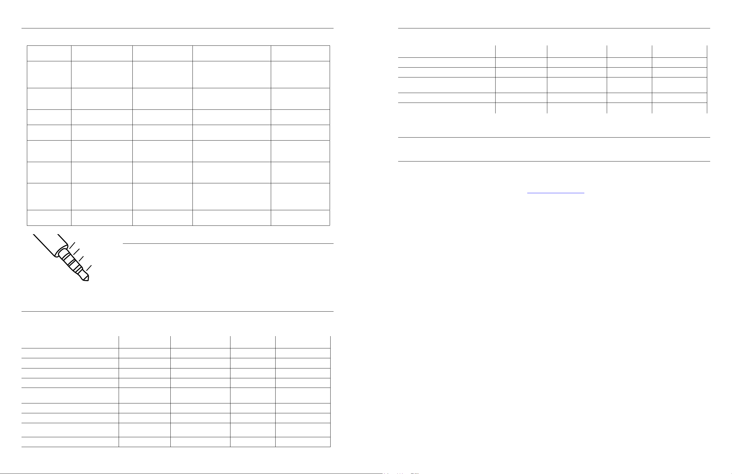
Microphone
Ground
Audio (right)
Audio (left)
Microphone/Headset Jack Difference
The jack on the Digi-Wave 400 series is different than older devices. The
wiring diagram in this section explains the internal wiring. See the pinout
diagram for details.
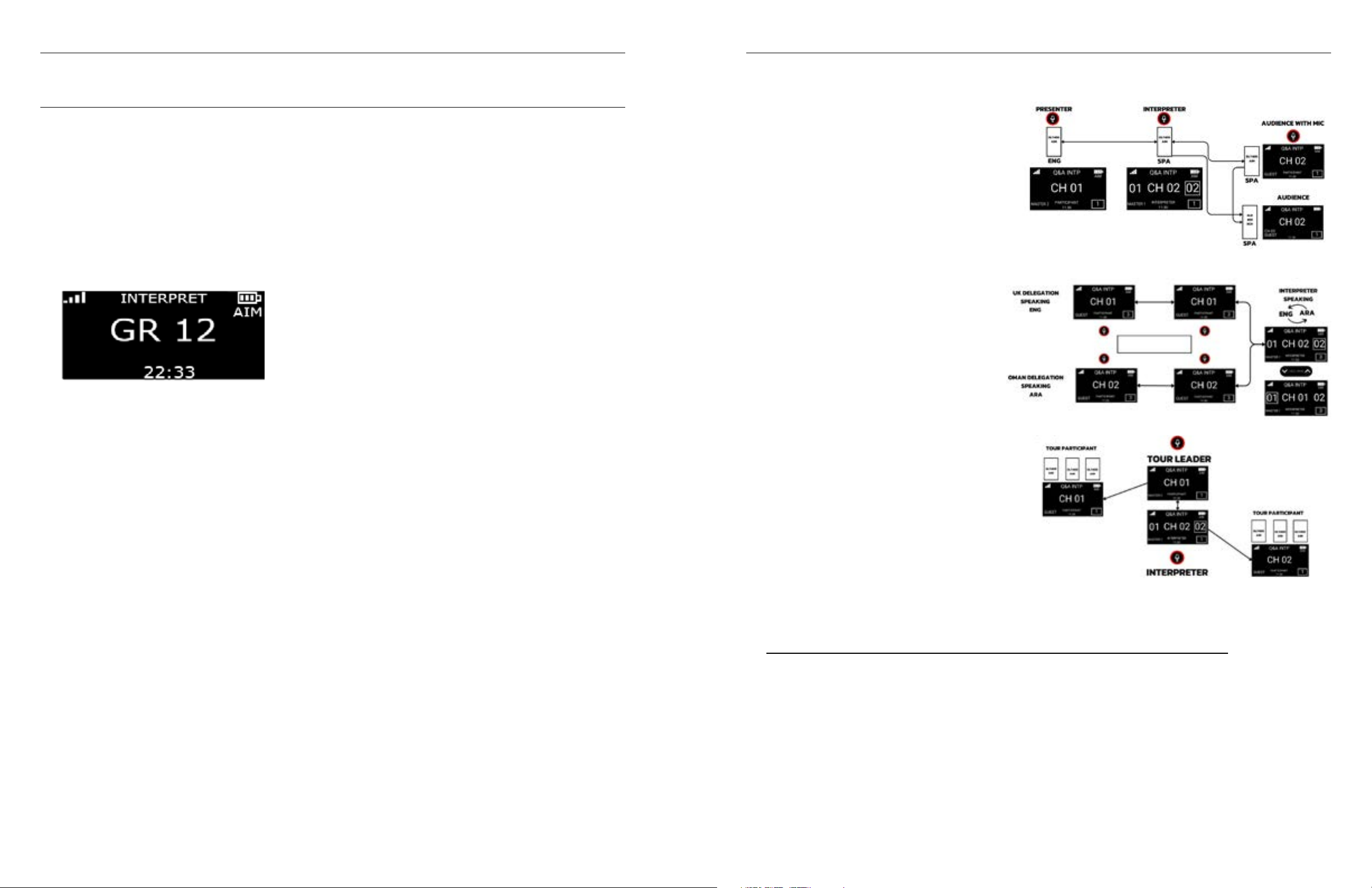
Differences Between Historical Digi-Wave DLTs
This chart covers feature differences only, not features common to all DLTs, based off the most common firmware
versions. The features available are shown in the chart below. If blank, the feature is not available.
Description
Quick Group Change √ √ √
Voting Function √
Receive Only (1-way mode) √ √ √
Speaker Only (2-way mode) √ √ √
Clock or Group displayed on Main
Screen
Talk Timer √
Auto Shut-off 5 minutes 5 minutes 5 minutes 2 minutes
Push-to-Talk & Push-and-Latch
Mic Gain Default Level 33 33 33 36
DLT 400
Optional Clock Optional Clock or Group
√
(Guest units only)
DLT 300 DLT 100 2.0 DLT 100
√
(Guest units only)
Clock Clock
√
(Guest units only)
2322
Page 13
Digi-Wave 400 Series Digi-Wave 400 Series
Advanced Interpretation Module
The Advanced Interpretation Module (AIM) introduces the following new features to a Digi-Wave® system:
• Q&A Mode
• 24-Channel Interpretation Mode
• Control Function
• Channel Naming
• Channel Sub-Groups
Advanced Interpretation Module (AIM) Features are only available for the DLT 400-AIM variant of the DLT 400
transceiver. To check if your DLT is the AIM variant, check if the word “AIM” is present under the battery symbol
on the display. Contact your local Williams AV representative regarding possible upgrade paths to the DLT 400AIM variant.
Compatibility
• DLR 400 RCH units on firmware version 1.3.0 or higher are compatible. Contact your Williams AV
representative to upgrade your firmware.
• DLR 400 ALK units are not compatible with the special AIM features.
Interpretation Q&A Mode
Interpretation Q&A Mode is used to facilitate Questions and Answers between the audience and a presenter in
a bilingual setting. Q&A Mode can also be utilized in bilingual meetings and two-way tours since two open mics
for each language are available. This enables a fluent and natural interchange of opinions and commentary
across language barriers. Interpretation Q&A Mode is limited to two active languages.
Devices Required for Q&A Mode:
Scenarios for Q&A Mode
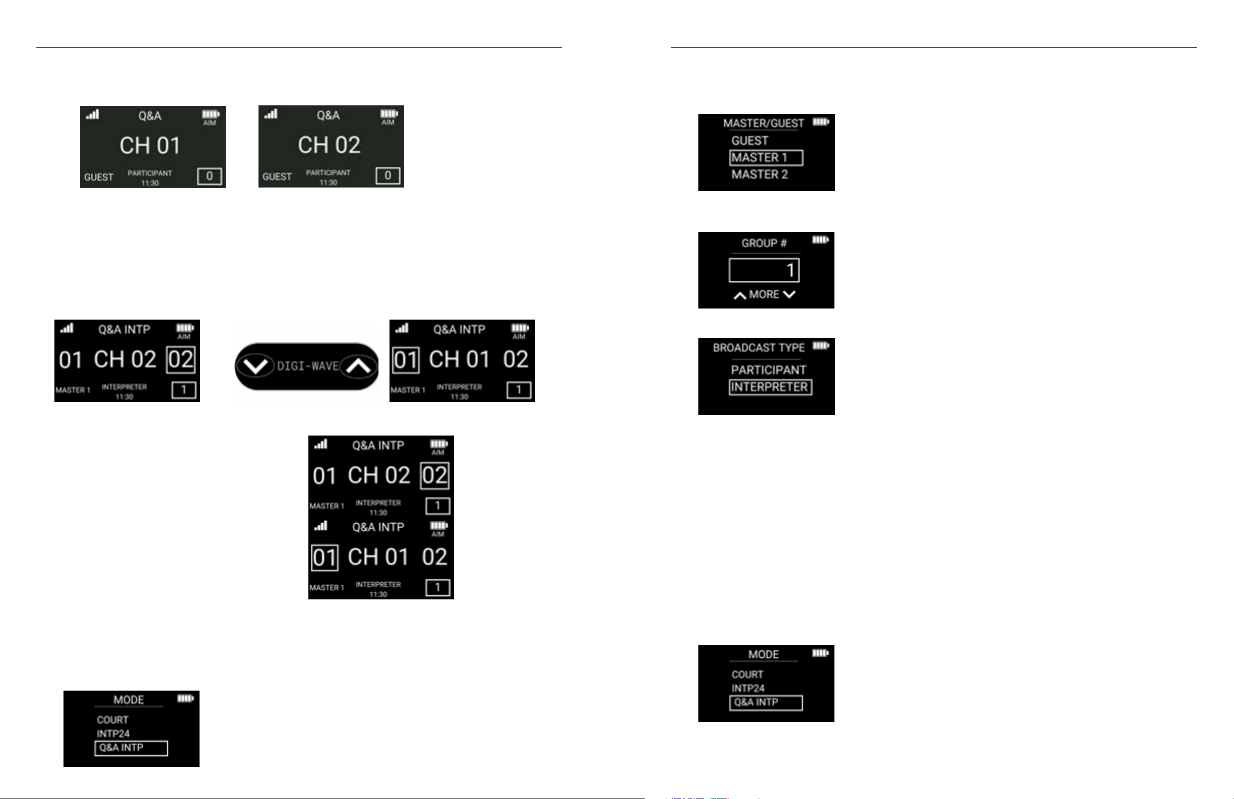
1. Scenario 1: Presentation with Interpreted
Audience Questions
The interpreter listens to CH01 and CH02
consecutively and can speak to the presenter
on CH01 and interpret what they hear to the
audience on CH02 or the interpreter is listening
to the audience on CH02 and interpreting what
they hear to the presenter on CH01:
2. Scenario 2: Bilingual Meetings with
Multiple Participants
Two speakers from both sides (CH01 and
CH02) can simultaneously speak and
the interpreter is interpreting to CH01 on
CH02. (Note a maximum of two people
per channel can speak at once and the
Interpreter can always speak).
3. Scenario 3: Bilingual Two-Way Tours
The interpreter listens to CH01 and CH02
simultaneously and can speak to the
presenter on CH01 and interpret what they
hear to the audience on CH02. When the
interpreter is listening to the audience on
CH02 then they can interpret what they hear
to the presenter on CH01.
1. 1 x DLT 400-AIM for Interpreter: Broadcast Type: Interpreter – Master 1- Channels 01 & 02 automatically
monitored, can switch output between Channels 01 & 02
2. 1 or more x DLT 400-AIM for presenter/ Delegation 1/ tour guide: Broadcast Type: Participant - Guest or
Master 2 – Channel 01
3. 1 or more x DLT 400-AIM for audience question/ Delegation 2/ tour participants: Broadcast Type: Participant
- Guest or Master 2 – Channel 02
4. 1 or more x DLR 400 RCH Listen Only, for audience members/ Delegates/ tour participants: Channel 02
Programming Scenarios
Scenario 1: Presentation with Interpreted Audience Questions
Devices Required
1. 1 x DLT 400-AIM for Interpreter: Broadcast Type: Interpreter – Master 1- Channels 01 & 02 automatically
monitored, can switch output between Channels 01 & 02
2. 1 or more x DLT 400-AIM for presenter(s): Broadcast Type: Participant - Guest or Master 2 – Channel 01
3. 1 or more x DLT 400-AIM for audience questions: Broadcast Type: Participant - Guest or Master 2 – Channel
02
4. 1 or more x DLR 400 RCH for audience members (listen only): Channel 02
Q&A Interpretation mode supports two languages.
· CH01 is the language of the presenter.
· CH02 is the interpreted language.
2524
Page 14
Digi-Wave 400 Series Digi-Wave 400 Series
BOTH channels are available to the audience.
Simultaneous listening
The interpreter will listen to the audio feed from both CH01 and CH02 simultaneously. The interpreter will
toggle their output between CH01 and CH02 depending on which language they are currently interpreting in.
Switching channels
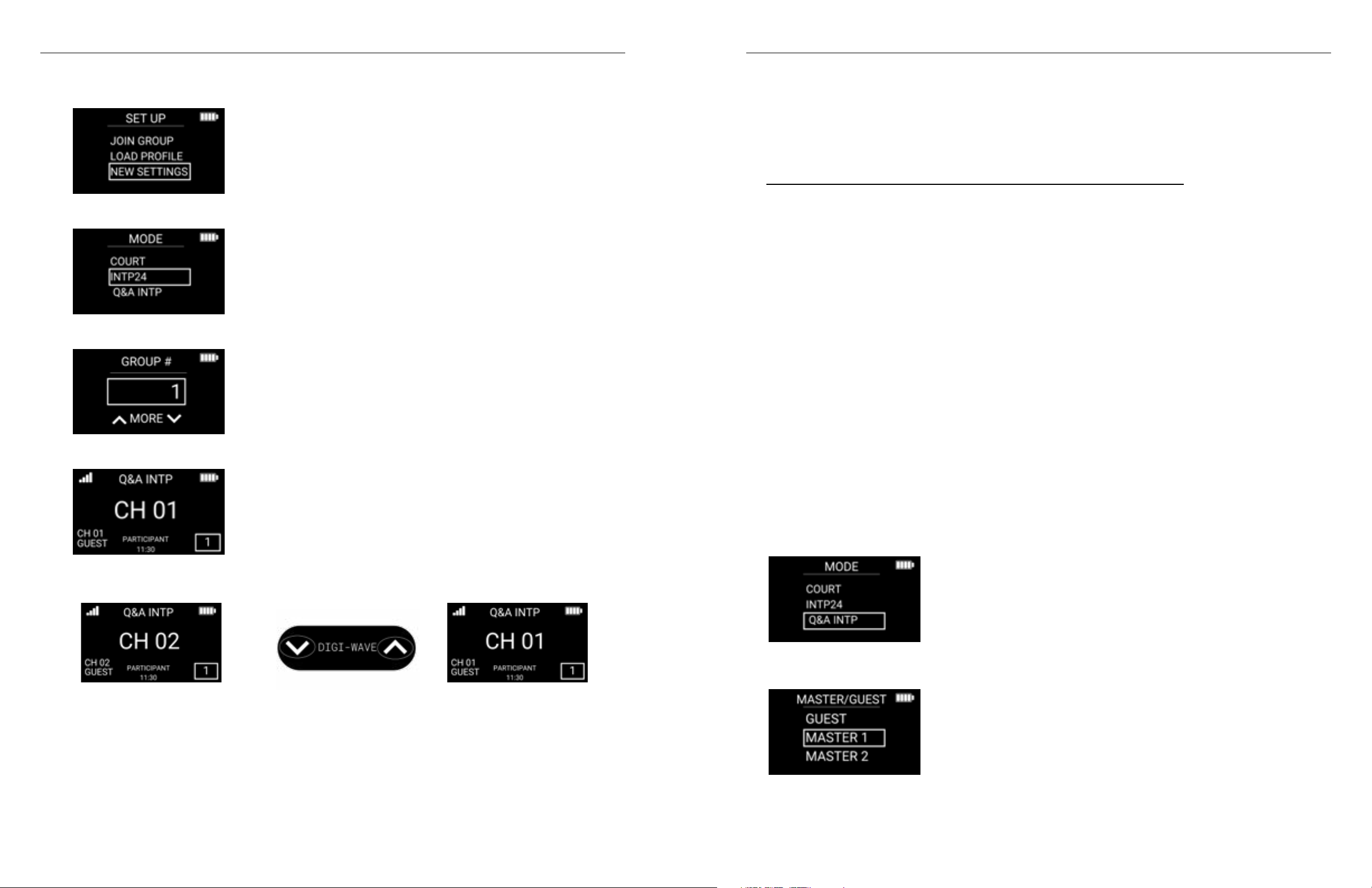
To switch channels, the Interpreter hits the up or down arrow; A square will surround the channel number that
the device is speaking to.
Example of an interpreter switching from output CH 02 to channel 01:
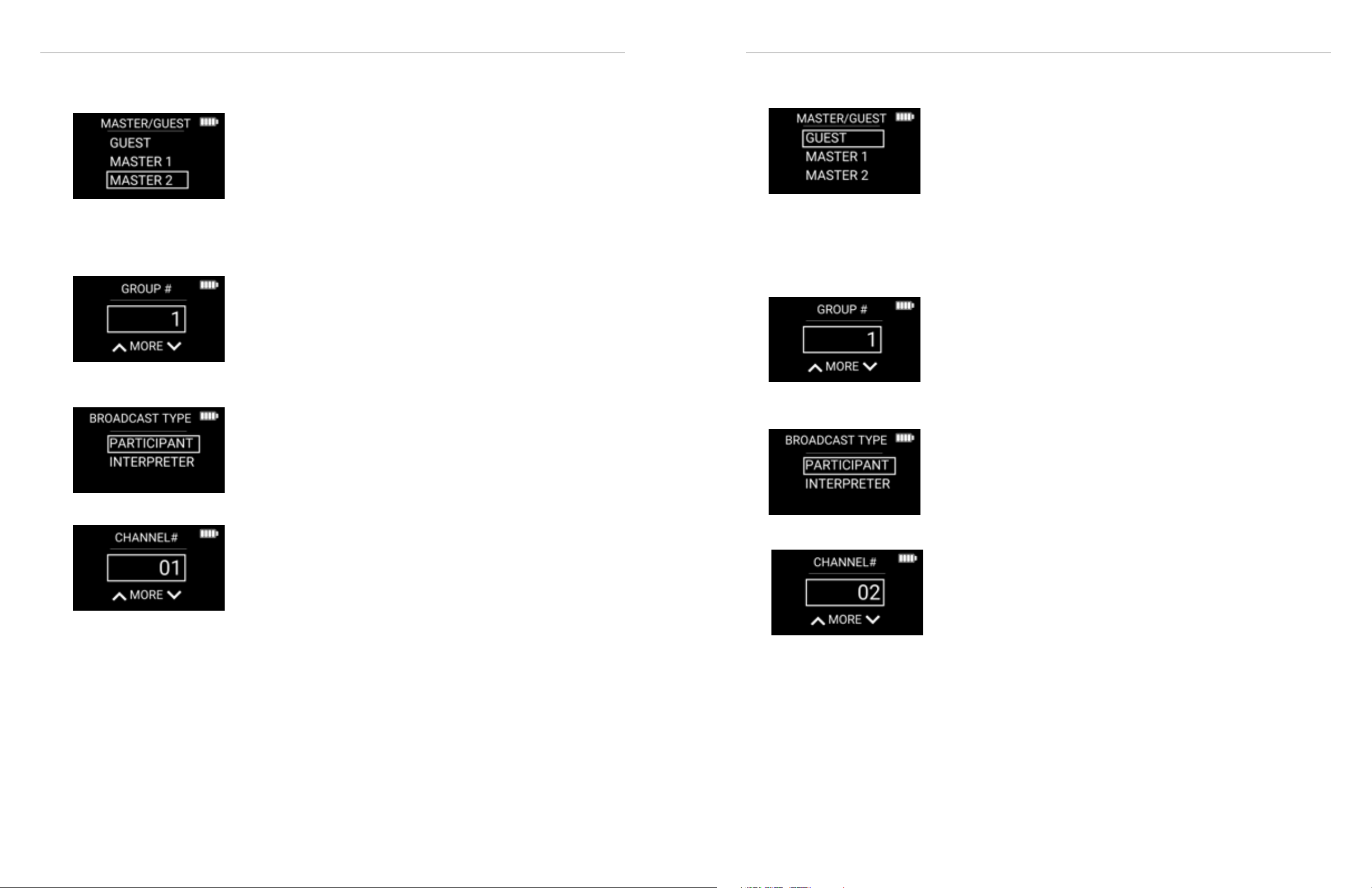
3. MASTER/GUEST: Master 1. This selection is usually recommended for the interpreter. Every Q&A system
requires exactly one Master 1. Master 2 is optional.
4. GROUP #: Choose a group number. All DLTs and DLRs in the Q&A system need to be connected to the
same group.
5. BROADCAST TYPE: INTERPRETER
Interpreting Questions
When interpreting from the main presenter
(CH01) into the target language (CH02), output
CH02 will be active on the interpreter DLT.
When interpreting a question from the audience
(CH02) back to the presenter (CH01), output CH01
will be active on the interpreter DLT.
A. Interpreter DLT
1. Enter programming mode by holding the menu/select button for three seconds, choose your
programming language, then select new settings. (Reminder the power button can be used as a back
function for mistakes.)
2. MODE: Q&A INTP
6. CLOCK MODE: As desired (12 HOUR or 24 HOUR)
7. CLOCK: Set current time if desired. All units in the Q&A system will synchronize their time to the MASTER 1
unit.
8. ADVANCED SETTINGS: In most cases, there is no need to go into advanced settings. If you choose NO, then
the programming is done. For more information on Advanced Settings, reference page 12 of the user manual.
9. Press TALK to turn on the TALK button for the Interpreter unit.
*Note: it is possible to program multiple interpreter units for a setting where several interpreters take turns interpreting.
However, only one interpreter can have their TALK button pressed at the same time. An interpreter unit programmed as a
MASTER 1 unit can take over the open mic from an interpreter unit programmed as GUEST. An interpreter unit programmed
as a GUEST can’t take over the open mic from an interpreter unit programmed as MASTER 1 until the MASTER 1 unit presses
the TALK button to make it inactive.
B. Presenter DLT
1. Enter programming mode by holding the menu/select button for three seconds, choose your
programming language, then select new settings. (Reminder the power button can be used as a back
function for mistakes.)
2. MODE: Q&A INTP
2726
Page 15
Digi-Wave 400 Series Digi-Wave 400 Series
3. MASTER/GUEST: MASTER 2.
This selection is usually recommended for the presenter. Master 2 is optional, but it enables the presenter to
always have their TALK button on without risking being bumped off if there are too many open mics in the
system.
4. GROUP #: Choose the same group number as the interpreter.
5. BROADCAST TYPE: PARTICIPANT. Both presenter DLTs and DLTs for audience questions are programmed as
PARTICIPANT.
2. MASTER/GUEST: GUEST.
• This selection is usually recommended for audience Q&A DLT. Depending on the event, you may
choose to designate a DLT for audience questions as MASTER 2. If the audience question DLT is
programmed as Master 2, it enables this DLT to always have their TALK button on when desired without
risking being bumped off if there are too many open mics in the system. An unlimited number of
Master 2 units are possible in a Q&A System.
3. GROUP #: Choose the same group number as the interpreter.
4. BROADCAST TYPE: PARTICIPANT. Both presenter DLTs and DLTs for audience questions are programmed
as PARTICIPANT.
6. CHANNEL: 01. Choose Channel 01 for the presenter language.
7. CLOCK MODE: As desired (12 HOUR or 24 HOUR)
8. ADVANCED SETTINGS: In most cases, there is no need to go into advanced settings. If you choose NO, then
the programming is done. For more information on Advanced Settings, reference page 12 of the User Manual
for more information.
9. Press TALK to turn on the TALK button.
C. Audience Question DLT
The following steps are for a DLT to be used as a microphone for audience questions. We recommend using
the plug mount microphone MIC 414 with the DLT 400-AIM unit. Several DLTs may be designated for audience
questions, but only two microphones can be active on CH 02 for audience questions at the same time. (1024
DLTs total can be part of a Q&A system.) (Reminder the power button can be used as a back function for
mistakes.)
1. Enter programming mode by holding the menu/select button for three seconds, choose your
programming language, then select new settings.
5. CHANNEL: 02. Choose Channel 02 for the audience question language.
6. CLOCK MODE: As desired (12 HOUR or 24 HOUR)
7. ADVANCED SETTINGS: In most cases, there is no need to go into advanced settings. If you choose NO,
then the programming is done. For more information on Advanced Settings, reference page 12 of the User
Manual for more information.
8. Press TALK to turn on the TALK button.
D. Audience DLR
The following steps are for DLRs to be used as listen only units for the audience to listen to an interpreted
language.
1. Enter programming mode by holding the menu/select button for three seconds and choose your
programming language. (Reminder the power button can be used as a back function for mistakes.)
2928
Page 16
Digi-Wave 400 Series Digi-Wave 400 Series
2. SET UP: JOIN GROUP
3. Mode: Select Q&A INTP
4. SELECT GROUP: Choose the same group number as the interpreter.
5. The DLR will be on channel 01.
questions from the audience. One can be programmed to channel 02 and be used when questions are in one
language and one can be programmed to channel 01 and be used when the questions are asked in a different
language.
- You may reprogram the presenter DLT from Channel 01 to Channel 02 – and the audience question DLT
from Channel 02 to Channel 01
Scenario 2: Bilingual Meeting with Multiple Participants
Q&A Mode may be used in bilingual settings where multiple participants need to be able to ask questions or
participate in a discussion. This mode is useful for meetings where several delegation members in two different
languages should be able to have their opinions interpreted into the other language.
Q&A Interpretation mode supports two languages. CH01 is the language of one delegation. CH02 is the
language of the other delegation. Two microphones can be active for each language at any one time, enabling
two delegates to speak seamlessly at the same time while the interpreter interprets into the other language.
The interpreter will listen to the audio feed from both CH01 and CH02 simultaneously. The interpreter will
toggle their output between CH01 and CH02 depending on which language they are currently interpreting into.
When interpreting from delegation 1 (CH01) language into delegation 2 (CH02) languages, output CH02 will be
active on the interpreter DLT. When interpreting from the delegation 2 (CH02) languages into the delegation 1
(CH01) language, output CH01 will be active on the interpreter DLT.
Devices Required
1. 1 x DLT 400-AIM for Interpreter: Broadcast Type: Interpreter – Master 1- Channels 01 & 02 automatically
monitored, can switch output between Channels 01 & 02
2. 1 or more x DLT 400-AIM for language 1: Broadcast Type: Participant - Guest or Master 2 – Channel 01
3. 1 or more x DLT 400-AIM for language 2: Broadcast Type: Participant - Guest or Master 2 – Channel 02
4. Optional: 1 or more x DLR 400 RCH for listen only participants: Channel 01 or 02
A. Interpreter DLT:
1. Enter programming mode by holding the menu/select button for three seconds, choose your
programming language, then select new settings. (Reminder the power button can be used as a back
function for mistakes.)
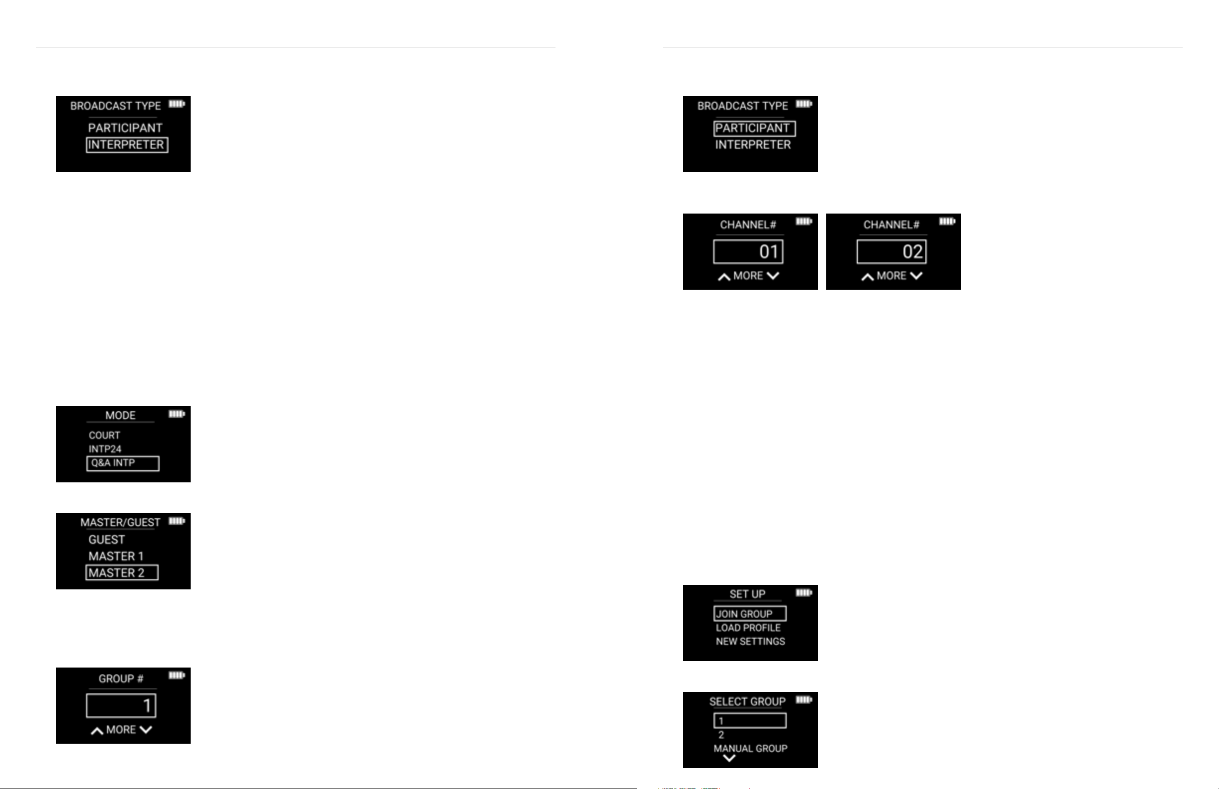
2. MODE: Q&A INTP
6. Use the arrow up button to go to CH 02 for the interpreted language. Some DLRs may be programmed to
listen to the presenter language on CH01 for assistive listening or other purposes.
What to do if the presenter language switches:
There is no need to reprogram the interpreter DLT or audience DLRs if the presenter languages switches.
If channel 01 originally represents English and channel 02 represents Spanish for example, these channel
numbers will continue to represent the same languages after a presenter language switch. There are several
ways to handle presenter and audience question DLTs.
- You may switch the DLT for the presenter with the DLT for audience questions.
- You may assign a presenter DLT to channel 01 and another presenter DLT to channel 02 and give presenters
in different languages different DLT units. The DLTs may easily be identified by different color silicon skins
(optional accessory CCS 061 BK, GR, RD or BL). In a similar manner, you may have two different DLTs for
3. MASTER/GUEST: Master 1. This selection is usually recommended for the interpreter. Every Q&A system
requires exactly one Master 1. Master 2 is optional.
4. GROUP #: Choose a group number. All DLTs and DLRs in the Q&A system need to be connected to the
same group.
3130
Page 17
Digi-Wave 400 Series Digi-Wave 400 Series
5. BROADCAST TYPE: INTERPRETER
6. CLOCK MODE: As desired (12 HOUR or 24 HOUR)
7. CLOCK: Set current time if desired. All units in the Q&A system will sync their time to the MASTER 1 unit.
8. ADVANCED SETTINGS: In most cases, there is no need to go into advanced settings. If you choose NO,
then the programming is done. For more information on Advanced Settings, reference page 12 of the User
Manual for more information.
9. Press TALK to turn on the TALK button for the Interpreter unit.
Note: It is possible to program multiple interpreter units for a setting where multiple interpreters take turn interpreting. However,
only one interpreter can have their TALK button pressed at the same time. An interpreter unit programmed as MASTER 1 can
take over the open mic from an interpreter unit programmed as GUEST. An interpreter unit programmed as a GUEST can’t take
over the open mic from an interpreter unit programmed as MASTER 1 until the MASTER 1 unit presses the TALK button to make it
inactive.
B. DLT for Delegation
1. Enter programming mode by holding the menu/select button for three seconds, choose your
programming language, then select new settings. (Reminder the power button can be used as a back
function for mistakes.)
2. MODE: Q&A INTP
5. BROADCAST TYPE: PARTICIPANT.
6. CHANNEL SELECTION. Choose Channel 01 for the delegation 1 language or Channel 02 for delegation 2
language.
7. CLOCK MODE: As desired (12 HOUR or 24 HOUR)
8. ADVANCED SETTINGS: In most cases, there is no need to go into advanced settings. If you choose NO,
then the programming is done. For more information on Advanced Settings, reference page 12 of the User
Manual for more information.
9. Press TALK to turn on the TALK button.
PROGRAMMING ADDITIONAL DELEGATION UNITS.
Go through the same steps as above for each DLT you would like to program for the delegation. Up to 1024
DLTs can be connected to the overall system. For key members, you can program them as Master 2 units, so
that they don’t risk being bumped off if somebody else presses their TALK button. Keep in mind that only
two microphones may be active at the same time for each delegation (channel/language) (in addition to the
interpreter). If you would like to have a set-up where a new delegate is not allowed to “butt in” and talk before
another delegate has turned off their TALK button, then program all delegate DLTs as Master 2 units. Unlimited
units can be programmed as Master 2.
3. MASTER/GUEST: MASTER 2.
We recommend programming the DLT for the most important member of the delegation as Master 2. Master 2
is optional, but it enables key delegation members to always have their TALK button on when speaking without
risking being bumped off if there are too many open mics in the system. Two open mics are allowed at the same
time for each delegation (channel/language) in addition to the interpreter.
4. GROUP #: Choose the same group number as the interpreter.
C. DLR Programming
The following steps are for DLRs to be used as listen only devices. DLRs may be used for example for junior
delegation members who need to hear the conversation in one of the languages but are not expected to
participate.
1. Enter programming mode by holding the menu/select button for three seconds, choose your
programming language.
2. SET UP: JOIN GROUP
3. SELECT GROUP: Choose the same group number as the interpreter.
3332
Page 18
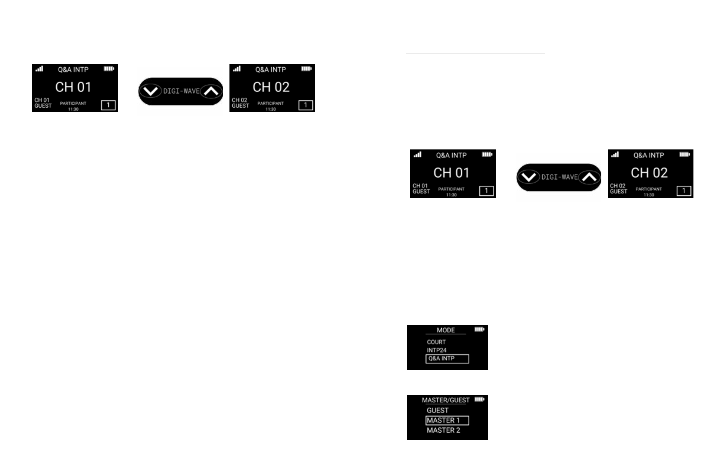
Digi-Wave 400 Series Digi-Wave 400 Series
4. Channel: The DLR will be on channel 01. Participant can choose to listen to delegation 1 or delegation 2
language. Use the arrow up button to go to CH 02 if desired.
Scenario 3: Bilingual Two-Way Tour
Q&A Mode can be utilized in bilingual two-way tours to enable all participants to freely ask questions in their
language to be interpreted back to the tour leader.
Q&A Interpretation mode supports two languages. CH01 is the language of the tour leader(s) and possibly
some of the tour participants. CH02 is the language of tour participants who require interpretation into another
language. Two microphones can be active for each language at any one time, enabling two tour leaders to
speak seamlessly at the same time while the interpreter interprets into the other language.
The interpreter will listen to the audio feed from both CH01 and CH02 simultaneously. The interpreter will
toggle their output between CH01 and CH02 depending on which language they are currently interpreting in.
When interpreting from the tour leader’s language into the tour participant’s target language, output CH02
will be active on the interpreter DLT. When interpreting questions from the tour participants back to the tour
leader, output CH01 will be active on the interpreter DLT.
Interpreter output: CH02 Interpreter output: CH01
Devices required for Scenario 3: Bilingual Two-Way Tour
1. 1 x DLT 400-AIM for Interpreter: Broadcast Type: Interpreter – Master 1- Channels 01 & 02 automatically
monitored, can switch output between Channels 01 & 02
2. 1 or more x DLT 400-AIM for tour leader: Broadcast Type: Participant - Guest or Master 2 – Channel 01
5. 1 or more x DLT 400-AIM for tour participants: Broadcast Type: Participant - Guest or Master 2 – Channel 02
3. Optional: 1 or more x DLR 400 RCH for listen only participants: Channel 01 or 2
A. Interpreter DLT Programming
1. Enter programming mode by holding the menu/select button for three seconds, choose your
programming language, then select new settings. (Reminder the power button can be used as a back
function for mistakes.)
2. MODE: Q&A INTP
3. MASTER/GUEST: Master 1. This selection is usually recommended for the interpreter. Every Q&A system
requires exactly one Master 1. Master 2 is optional.
3534
Page 19
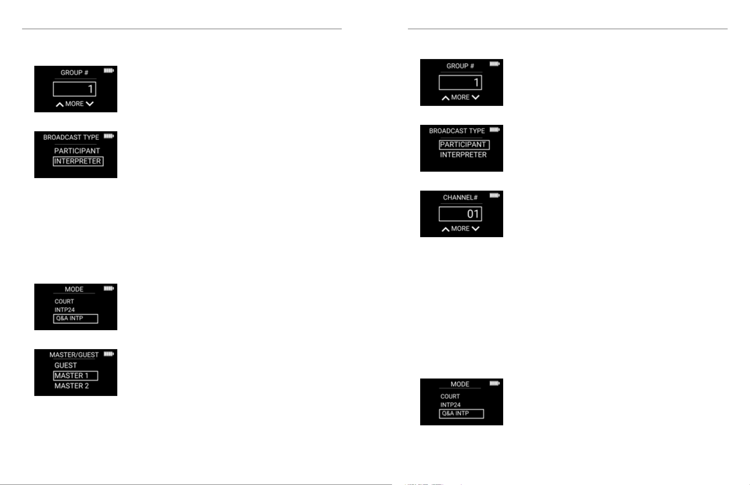
Digi-Wave 400 Series Digi-Wave 400 Series
4. GROUP #: Choose a group number. All DLTs and DLRs in the Q&A system need to be connected to the
same group.
5. BROADCAST TYPE: INTERPRETER
6. CLOCK MODE: As desired (12 HOUR or 24 HOUR)
7. CLOCK: Set current time if desired. All units in the Q&A system will sync their time to the MASTER 1 unit.
8. ADVANCED SETTINGS: In most cases, there is no need to go into advanced settings. If you choose NO,
then the programming is done. For more information on Advanced Settings, reference page 12 of the User
Manual for more information.
9. Press TALK to turn on the TALK button for the Interpreter unit.
4. GROUP #: Choose the same group number as the interpreter.
5. BROADCAST TYPE: PARTICIPANT.
6. CHANNEL: 01. Choose Channel 01 for the Tour Leader language.
B. Tour Leader DLT Programming
1. Enter programming mode by holding the menu/select button for three seconds, choose your
programming language, then select new settings. (Reminder the power button can be used as a back
function for mistakes.)
2. MODE: Q&A INTP
3. MASTER/GUEST: MASTER 2.
• We recommend programming the Tour Leader Tour as Master 2. Master 2 is optional, but it enables
the tour leader to always have their TALK button on without risking being bumped off if there are too
many open mics in the system. Two open microphones are allowed at the same time for the tour leader
channel/language (in addition to the interpreter).
7. CLOCK MODE: As desired (12 HOUR or 24 HOUR)
8. ADVANCED SETTINGS: In most cases, there is no need to go into advanced settings. If you choose NO,
then the programming is done. For more information on Advanced Settings, reference page 12 of the User
Manual for more information.
9. Press TALK to turn on the TALK button.
PROGRAMMING ADDITIONAL TOUR LEADER UNITS
Go through the same steps as above for each DLT you would like to program for the additional tour leaders. You
may program an unlimited number of Master 2 units for tour leaders, so that they don’t risk being bumped off if
somebody else presses their TALK button. However, keep in mind that only two microphones may be active at
the same time for the tour leader channel/language (in addition to the interpreter).
C. DLT Programming for Tour Participants Requiring Interpretation
1. Enter programming mode by holding the menu/select button for three seconds, choose your
programming language, then select new settings. (Reminder the power button can be used as a back
function for mistakes.)
2. MODE: Q&A INTP
3736
Page 20
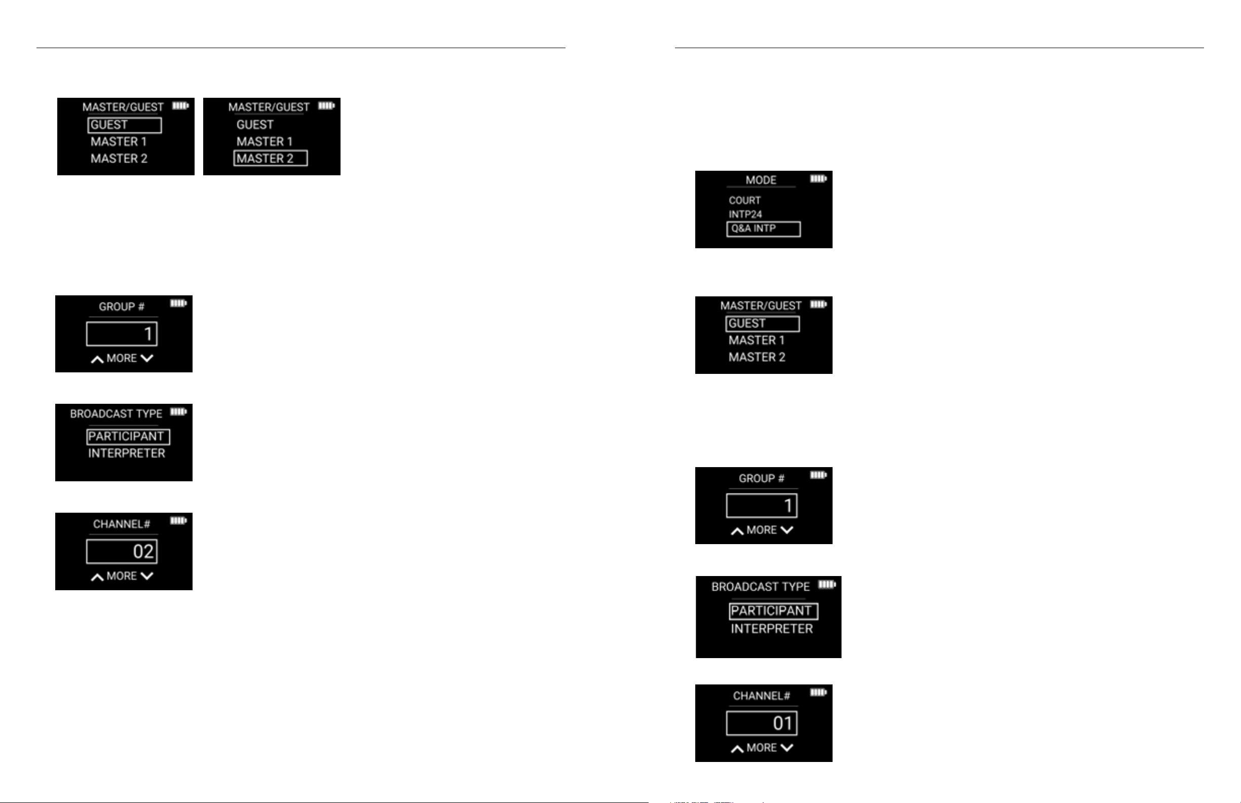
Digi-Wave 400 Series Digi-Wave 400 Series
3. MASTER/GUEST: GUEST or MASTER 2.
• When to choose: Master 2 or Guest: Choose Master 2 if VIP guest who may need to control the mic,
Choose Guest for participants in general.
• Typically, Tour Participant DLTs would be programmed as GUEST units. However, VIP participant DLTs
may be programmed as Master 2. Master 2 is optional, but it enables the VIP participants to turn on
their TALK button without risking being bumped off if there are too many open mics in the system. Two
open microphones are allowed at the same time for the interpreted channel/language (in addition to
the interpreter).
4. GROUP #: Choose the same group number as the interpreter.
D. Tour Participants Using the Same Language as the Tour Leader DLT
Programming (Optional)
1. Enter programming mode by holding the menu/select button for three seconds, choose your
programming language, then select new settings. (Reminder the power button can be used as a back
function for mistakes.)
2. MODE: Q&A INTP
3. MASTER/GUEST: GUEST or MASTER 2.
5. BROADCAST TYPE: PARTICIPANT.
6. CHANNEL: 02. Choose Channel 02 for the Tour Participant Interpreted Target language.
7. CLOCK MODE: As desired (12 HOUR or 24 HOUR)
8. ADVANCED SETTINGS: In most cases, there is no need to go into advanced settings. If you choose NO,
then the programming is done. For more information on Advanced Settings, reference page 12 of the User
Manual for more information.
9. Press TALK to turn on the TALK button.
PROGRAMMING ADDITIONAL PARTICIPANT UNITS
Go through the same steps as above for each DLT you would like to program for the additional participants.
• Typically, Tour Participants would be programmed as GUEST units. However, VIP participant DLTs may
be programmed as Master 2. Master 2 is optional, but it enables the VIP participants to turn on their
TALK button without risking being bumped off if there are too many open mics in the system. Two open
microphones are allowed at the same time for the interpreted channel/language (in addition to the
interpreter).
4. GROUP #: Choose the same group number as the interpreter.
5. BROADCAST TYPE: PARTICIPANT.
6. CHANNEL: 01. Choose Channel 01 for the Tour Leader language.
3938
Page 21
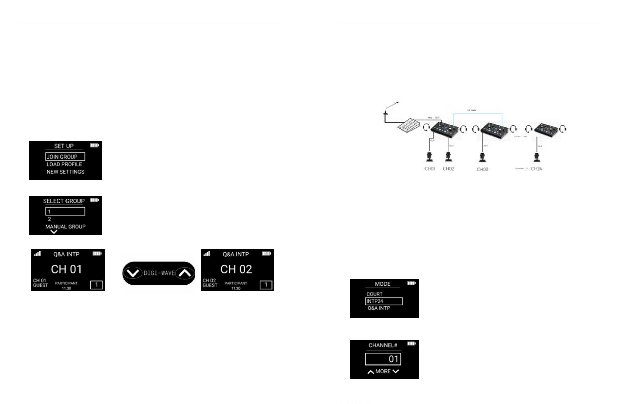
Digi-Wave 400 Series Digi-Wave 400 Series
7. CLOCK MODE: As desired (12 HOUR or 24 HOUR)
8. ADVANCED SETTINGS: In most cases, there is no need to go into advanced settings. If you choose NO,
then the programming is done. For more information on Advanced Settings, reference page 12 of the User
Manual for more information.
1. Press TALK to turn on the TALK button.
2. PROGRAMMING ADDITIONAL PARTICIPANT UNITS: Go through the same steps as above for each DLT you
would like to program for the additional participants.
E. DLR (Listen Only) Programming (Optional)
The following steps are for DLRs to be used as listen only devices. DLRs may be used for tour participants who
need to hear the conversation in one of the languages but are not expected to participate.
1. Enter programming mode by holding the menu/select button for three seconds, choose your
programming language.
2. SET UP: JOIN GROUP
3. SELECT GROUP: Choose the same group number as the interpreter.
24-Channel Interpretation Mode
24-channel mode is intended mainly for large interpretation conferences. As the name implies, it allows for
24 channels/languages instead of the floor + 14 languages supported in standard interpretation mode. One
difference compared to Digi-Wave® standard interpretation mode is that the 24-channel mode is a pure
one-way mode. This means that an interpreter DLT on one of the channels works as a transmitter only. An
interpreter using a DLT can’t hear the floor language directly through the DLT. Instead, the interpreter would
typically use an interpreter console such as the IC-2 to hear the floor language.
Devices required for 24-channel mode
1. 1 x DLT 400-AIM for Interpreter: Broadcast Type: Interpreter – Master Channel 01
2. 1 or more x DLT 400-AIM for Interpreters languages 02-24: Broadcast Type: Interpreter – Master – Channel
02-24
3. 1 or more x DLR 400 RCH for listen only participants: Channels 01-24
4. Optional: 1 or more x DLT 400-AIM as repeater units: Broadcast Type: Repeater – Guest – Channel 01-24
4. The DLR will be on channel 01. Use the arrow up button to go to channel 02 if desired.
Programming for 24-Channel Interpretation
A. Interpreter DLT Programming
1. Enter programming mode by holding the menu/select button for three seconds, choose your
programming language, then select new settings. (Reminder the power button can be used as a back
function for mistakes.)
2. MODE: INTP14
3. MASTER/GUEST: MASTER. One (and only one) interpreter DLT has to be set up as MASTER. The other
interpreter DLTs have to be set up as GUEST.
4140
Page 22
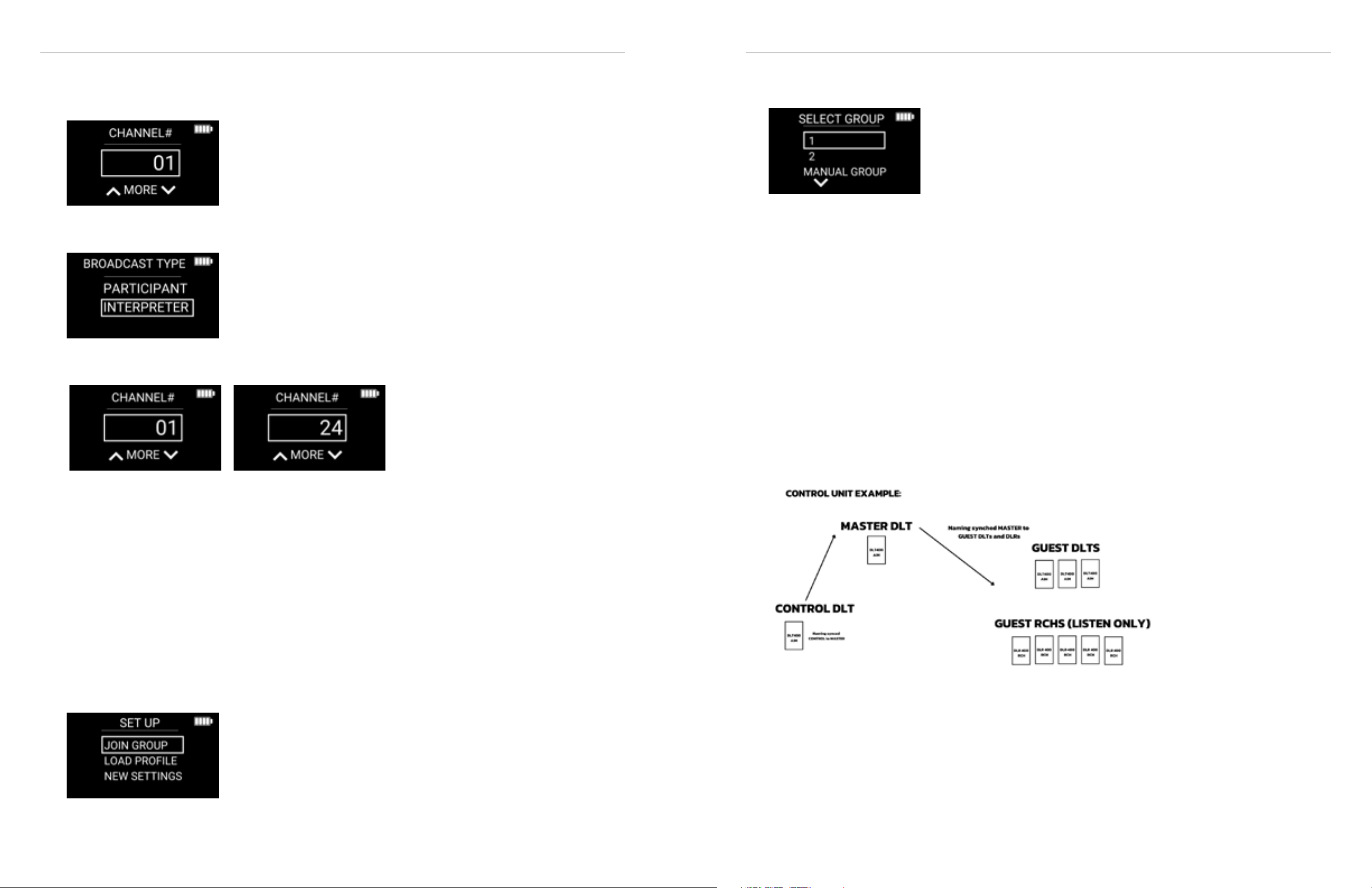
Digi-Wave 400 Series Digi-Wave 400 Series
4. GROUP #: Choose a group number. All DLTs and DLRs in the INTP24 system need to be connected to the
same group.
5. BROADCAST TYPE: INTERPRETER. Repeater units can be added to add range. Max. 1 repeater unit per
channel is allowed.
6. CHANNEL: 01. Choose channel 01 for the first channel. Additional interpreter DLTs will be on channels 02-
24.
3. SELECT GROUP: Choose the same group number as the interpreter.
The DLR will be on channel 01. Use the arrow up button to go to channel 02-24 if desired. Hold the arrow up
button to seek for active channels.
Control Function
A DLT 400-AIM device can be programmed is a CONTROL unit. This enables channel naming and sub-groups
to be set up offline. The control function makes it possible to make changes to a Digi-Wave® system without
interrupting an ongoing event. The control unit is synced to the MASTER when convenient, for example during
a break. All other DLTs and DLRs (RCH only) then inherit channel names and sub-group information from the
master unit. Channel naming and sub-group programming is only available through a DLT programmed as a
CONTROL unit.
The DLT 400-AIM functionality enables a CONTROL unit to be set up for all the interpretation modes:
• INTERPRET. (Standard interpretation mode incl. BILINGUAL and RELAY)
• INTP24 (24-channel interpretation mode)
• Q&A INTP (Interpretation with Question & Answer)
DLT 400-AIM does not enable channel naming and sub-groups for other Digi-Wave® modes such as Tour,
Hearing Assist, Intercom and Court mode).
See the sections “Channel Naming” and “Sub-Groups” for details on CONTROL unit programming.
7. CLOCK MODE: As desired (12 HOUR or 24 HOUR)
8. CLOCK: Set current time if desired. All units in the system will sync their time to the MASTER unit.
9. ADVANCED SETTINGS: In most cases, there is no need to go into advanced settings. If you choose NO,
then the programming is done. For more information on Advanced Settings, reference page 12 of the User
Manual for more information.
10. The TALK button will automatically be turned on, the first interpreter unit is ready.
ADDITIONAL INTERPRETER DLT UNITS:
Program additional interpreter DLT units in the same manner on channels 02-24 as GUEST units.
B. DLR (Listen Only) Programming
The following steps are for DLRs to be used for the audience to listen to interpreted languages.
1. Enter programming mode by holding the menu/select button for three seconds and choose your
programming language.
2. SET UP: JOIN GROUP
Channel Naming
The channel name can be any 3-letter ISO language abbreviation out of 100 common languages; OR custom
5-character names (letters, numbers, blank). Channel naming is done on a DLT programmed is a CONTROL unit.
The control unit is synced to the MASTER when convenient. All other DLTs and DLRs (RCH only) then inherit
channel names from the master unit. See the document “AIM List of Channel Names” for details on which
channel names are available.
4342
Page 23
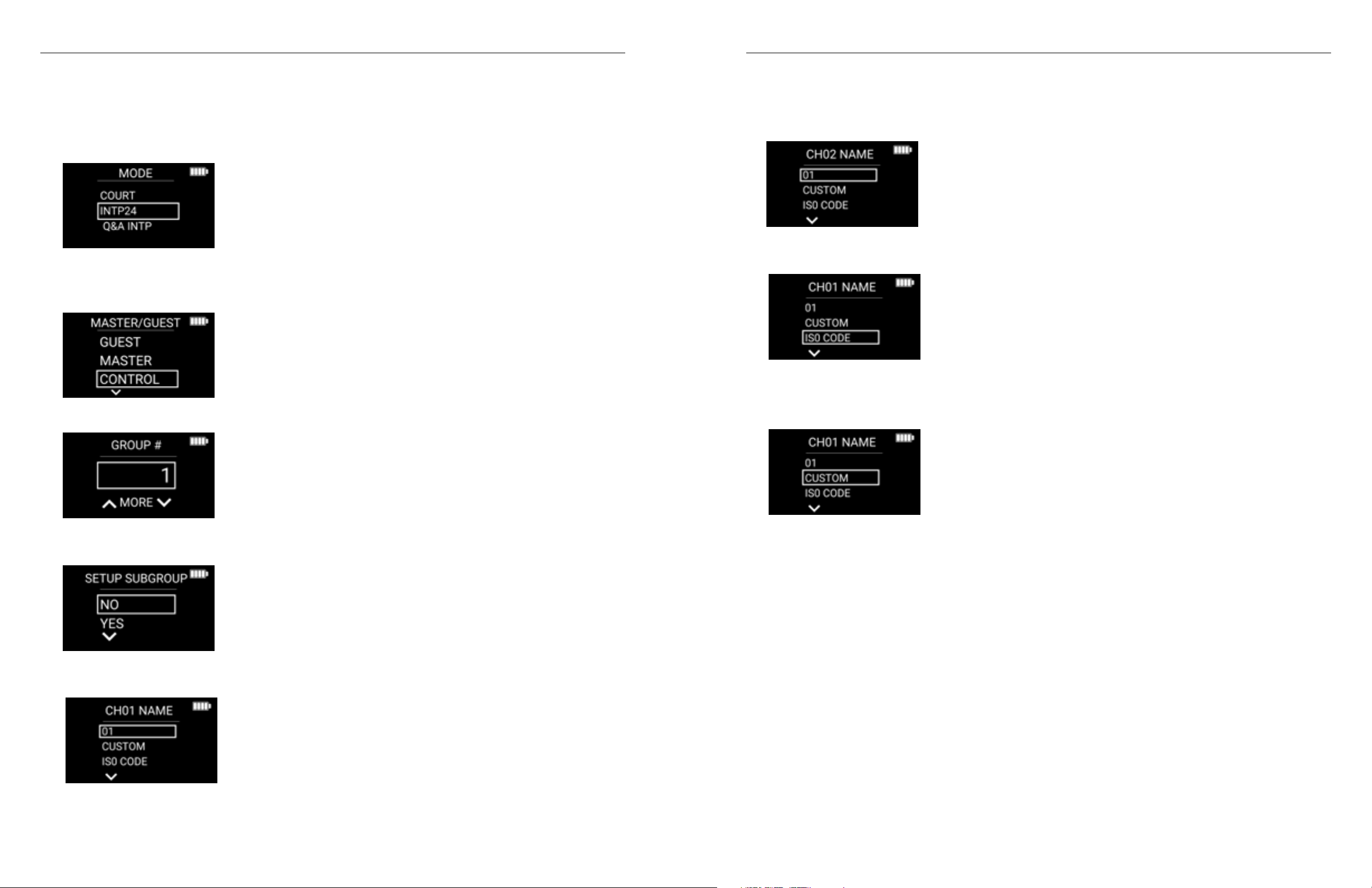
Digi-Wave 400 Series Digi-Wave 400 Series
Programming Channel Names
1. Enter programming mode by holding the menu/select button for three seconds, choose your
programming language, then select new settings.
2. MODE: INTERPRET, INTP24 or Q&A INTP.
3. Make sure you choose the same mode as the MASTER unit of the Digi-Wave® system. If the modes aren’t
the same, then the Control unit will not be able to synchronize with the Master unit.
4. MASTER/GUEST?: CONTROL.
5. GROUP #: Choose the same group number as the MASTER 1 of the system you wish to update.
If you keep 01 as the channel name, then you move to channel name
programming for channel 02.
If you choose ISO CODE,
Then, the next screen is: CH01 REGION: WORLD, EUR/AM, INDIA/SA. Choose region and then 3-letter language
code for desired language.
If you choose CUSTOM,
6. SETUP SUBGROUP: NO. Select NO if you don’t wish to set up a subgroup. See the SUBGROUP section for
details on setting up subgroups.
7. Select a CH01 NAME: The options include: 01, CUSTOM or ISO CODE. (For standard interpretation mode, you
can also program the channel 0 (floor language) name.)
• Then the next screen is LETTER 1-5: Choose between the letters in the English Alphabet, blank and
0-9. Program 5 letters for Channel 01. (Reminder the power button can be used as a back function for
mistakes.)
8. Once you have programmed the name for Channel 01, then the next step is Choosing Channel 02
(CH02) NAME: Same process as for Channel 01 name. You may name all the channels available for the
interpretation mode you are programming. If you don’t have a name for all the channels, then you may
jump to the end of programming by holding the enter button for three seconds. (Unprogrammed channel
names keep the default number as their name.)
9. SAVE: SAVE, SAVE AS PROFILE or CANCEL.
• Choose SAVE if you are ready to update the system now or soon.
• Choose SAVE AS PROFILE if you are planning to update the system at a later date and you may use the
same DLT for other purposes between now and then.
10. UPDATE SYSTEM: NO or UPDATE SYSTEM NOW.
• Choose NO if you want to save your settings, but you are not ready to update the system.
• Choose UPDATE SYSTEM NOW if you are ready to synchronize with the MASTER and all DLTs and DLRs
connected to that group.
11. UPDATE SYSTEM ARE YOU SURE? Choose UPDATE SYSTEM NOW to go ahead with the update.
• A bar showing the progress of the UPDATE will be visible both on the CONTROL units and the MASTER
unit. Once the update has been done a pop-up window showing UPDATE OK will be visible on the
control and master units. Channel naming will then be pushed out to all DLTs and DLRs which are
connected to the group. Note: DLTs and DLRs need to be connected to the MASTER unit (within radio
range and turned on) when the update is done in order to be updated.
4544
Page 24
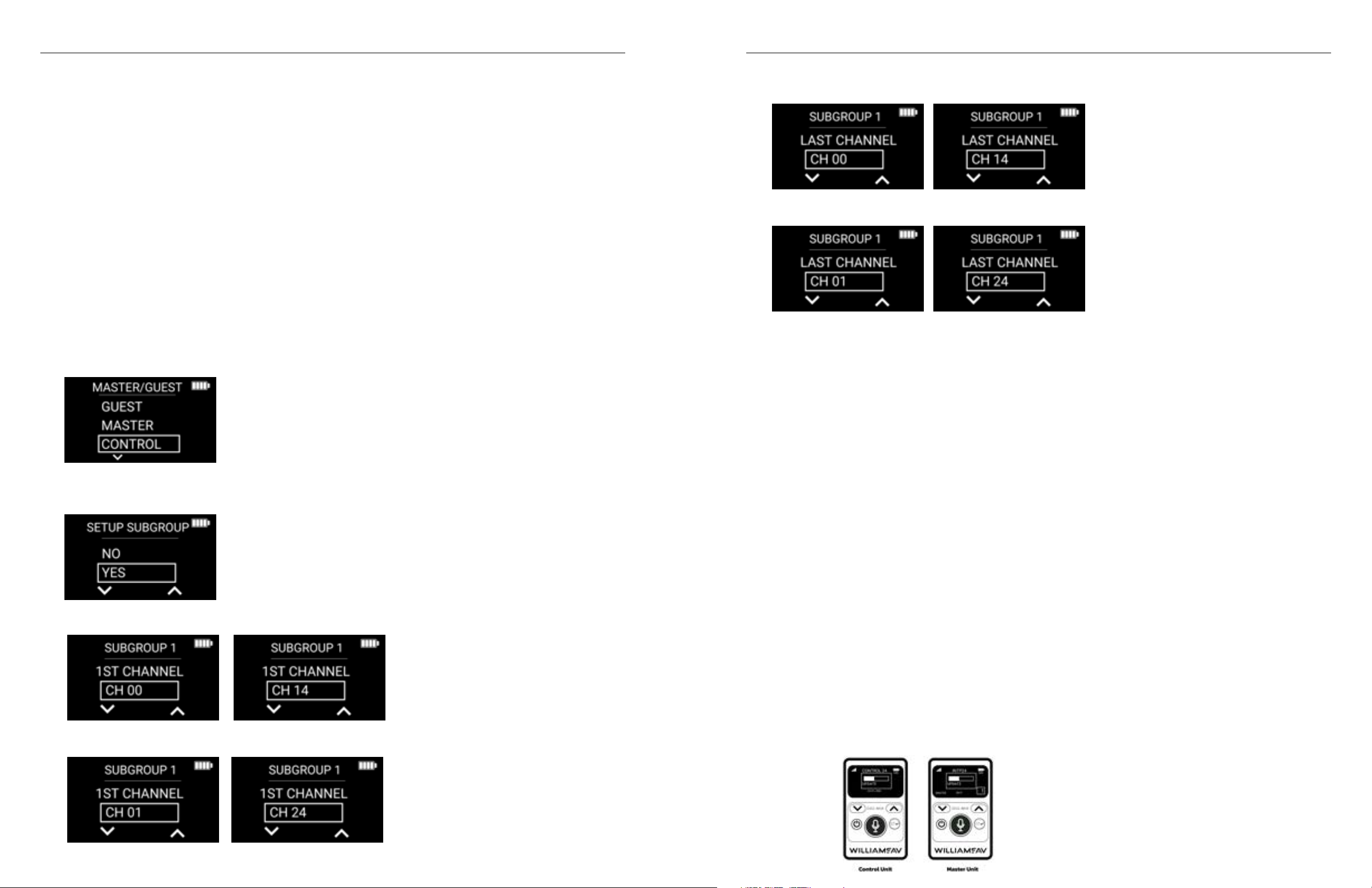
Digi-Wave 400 Series Digi-Wave 400 Series
• SUBGROUP 1 - LAST CHANNEL: CH 00-CH 14 for standard interpretation,
Verifying Channel Names
The current channel names programmed for the CONTROL unit are listed at the bottom of the display. You can
go scroll through the channels to see the names by using the up/down arrows.
Channel Sub-Groups
Channel subgroups are helpful in a situation where you don’t want all the channels to be visible to all
participants. For example, this may be the case when a large hall is sometimes divided into two or more
separate spaces. You can also utilize sub-groups to limit the number of channels visible on the receivers. For
example, if only channels 01-16 are active in 24-channel mode, then you could set up a subgroup for channels
01-16 and program the DLRs to be in that subgroup for the receivers to avoid seeing non-active channels.
Programming Sub-Groups
1. Enter programming mode by holding the menu/select button for three seconds, choose your
programming language, then select new settings.
2. MODE: Select INTERPRET, INTP24 or Q&A INTP.
• Make sure you choose the same mode as the MASTER unit of the Digi-Wave® system. If the modes
aren’t the same, then the Control unit won’t be able to synchronize with the Master unit.
3. MASTER/GUEST?: Select CONTROL.
4. GROUP #: Choose the same group number as the MASTER of the system you wish to update.
5. SETUP SUBGROUP: YES.
You must choose a higher number for the last channel than the first channel.
• CH 01-CH24 for INTP24.
7. SUBGROUP 2 - 1ST CHANNEL: CH 00-CH 14 for standard interpretation, CH 01-CH24 for INTP24. You must
program at least two subgroups in order to use the sub-group feature. There can be overlap between the
different subgroups. For example, you could have channels 01-05 for subgroup 1 and channels 03-08 for
subgroup 2.
8. SUBGROUP 2 - LAST CHANNEL: CH 00-CH 14 for standard interpretation, CH 01-CH24 for INTP24. You must
choose a higher number for the last channel than the first channel.
9. ADD SUBGROUP 3: NO or YES. Optional.
10. ADD SUBGROUP 4: NO or YES. Optional.
11. ACTIVE SUBGROUP: NO or YES. If you would like to update subgroups as soon as you update the system,
choose YES. If subgroups were previously active, the way to deactivate them is to go to this programming
step and choose ACTIVE SUBGROUP = NO and then update the system.
12. After adding 2-4 subgroups, you are taken to the channel naming menu. See Channel Naming section for
details. If you don’t want to name the channels, then you may jump to the end of programming by holding
the enter button for three seconds. (Channel names will then have the default number as their name.)
13. SAVE: SAVE, SAVE AS PROFILE or CANCEL.
• Choose SAVE if you are ready to update the system now or soon.
• Choose SAVE AS PROFILE if you are planning to update the system at a later date and you may use the
same DLT for other purposes between now and then.
6. SUBGROUP 1 - 1ST CHANNEL: CH 00-CH 14 for standard interpretation,
• CH 01-CH24 for INTP24.
14. UPDATE SYSTEM: NO or UPDATE SYSTEM NOW.
• Choose NO if you want to save your settings, but you’re not ready to update the system.
• Choose UPDATE SYSTEM NOW if you are ready to synchronize with the MASTER and all DLTs and DLRs
connected to that group.
15. UPDATE SYSTEM ARE YOU SURE?: Choose UPDATE SYSTEM NOW to go ahead with the update.
• A bar showing the progress of the UPDATE will be visible both on the CONTROL units and the MASTER
unit. Once the update has been done a pop-up window showing UPDATE OK will be visible on the
control and master units. Channel naming will then be pushed out to all DLTs and DLRs which are
connected to the group. Note: DLTs and DLRs need to be connected to the MASTER unit (within radio
range and turned on) when the update is done in order to be updated.
4746
Page 25

Digi-Wave 400 Series Digi-Wave 400 Series
Programming DLR (Listen Only) units for Sub-Groups
1. Enter programming mode by holding the menu/select button for three seconds, choose your
programming language, then select new settings.
2. MODE: INTERPRET, INTP24 or Q&A INTP.
3. GROUP #: Choose the same group number as the MASTER unit.
4. SUBGROUPS?: NO, SG1, SG2, SG3, SG4.
5. This determines which sub-group the DLR belongs to, meaning which channels it can listen to. If you
choose NO, then the DLR will have access to all channels (00-14 in standard interpretation mode, 01-24 in
24-channel mode).
• If you don’t want to go through additional options, hold the menu/select button for three seconds – you
will then finish programming and your DLR is now active within the chosen sub-group. (You may also
go through the additional options of tone, line-out gain, encryption and PIN code.)
• The DLR will be on the lowest channel of the sub-group. Use the arrow up button to go to channel 0224 if desired. Hold the arrow up button to seek for active channels. The DLR will show which sub-group
it is in the middle of the screen below the channel name if sub-groups are active.
Verifying Sub-Groups
You can verify which sub-groups are set up on a CONTROL unit by quickly pressing the menu/select button
several times. The pop-up window will first show the group number and firmware version. If you click the
menu/select button several more times, then it will show the different sub-groups.
Troubleshooting
Problem Cause What to Do
Power does not turn-on Dead battery Charge the battery, replace battery
Power turned off
automatically
Power doesn’t turn off Program Error
No audio or wrong audio in
headphones
Error in attendee checking
Can’t select receiving channel Transmitting channel is overlapping Set different transmitting channel
Can’t select group/channel on
receiver
Unable to transmit
Interpretation
DLT keeps turning off Master unit shut off Turn on / set Master
Can’t hear the speaker
A DLT will not sync to Master 1
Signal Strength is blinking
Buttons not functioning
Time of Day Incorrect
Master device can’t be found Turn on Master unit
Press reset button on the back of device (DLT
only)
Disconnection of headphone Check headphone connection
Master unit shut off Turn on / set Master
Different Group Number settings Set every unit to the same group number
Out of range
More than 1 Master exists in a group Set one Master per group
Obstacle exists Move to another place or move the obstacles
More than 2 units with same address exist
in a group
More than 2 units with same address exist
in a group
Receiver is locked
Check the mode for simultaneous
interpretation mode
More than 2 Master units exist Set one Master only
Mic Sensitivity too low
Master unit shut off
Out of Range Bring the unit closer to the Master
Master is Off Turn Master unit on
Master is adjusting settings On Master, exit settings.
No/Incorrect Secure Code Make the secure code the same as the Master
Wrong Group Number Make group numbers match the Master
The Guest has not found a Master to sync
to.
Super lock enabled Disable super lock
Time of Day on Master 1 is Incorrect.
(All units sync their time from Master 1)
Move to within the range of 100ft (outside) or
200 ft (inside) from the Master unit
Set different address
Set different address
See “Locking the DLT Buttons and Screen” on
page 6
Set simultaneous interpretation mode
Adjust the sensitivity for the microphone you
have. (Mic 044-2p is about 33, Mic 068 is about
17).
See why the Master shut off and correct the
problem. Turn on the Master and verify the
battery level.
Program at least one unit as the Master or turn
on the existing Master. Verify that the Group
numbers match. Master must not be in settings
menu.
Set time of day to the correct time on Master 1.
4948
Page 26

Digi-Wave 400 Series Digi-Wave 400 Series
Specifications - DLT 400 Transceiver
Dimensions 2.60”W x 4.22”H x 0.50”D
Weight 3.3 oz (94 g) including battery
Color Black/Silver (Front/Back)
Case Material Black ABS plastic
Battery type Lithium Polymer with smart charge built into transceiver; 1800 mAH
Battery life Up to 16 hrs talk time per charge@ 1ch Tx and 1ch Rx
Power Save Auto Sleep Mode after 5 minutes of no RF signal from compatible devices
Charge time 5 hrs. approx.
System Voltage OLED 14VDC; RF 5VDC; Logic 3.3 VDC
Operating frequencies 2.4 GHz (ISM band); 2402 – 2476 MHz FHSS
Audio Frequency response
(-3dB Level)
SNR 73 dB (A-weighted, default Rx volume with mic input )
THD 0.1 % (Default Volume, 1kHz)
Microphone input Internal microphone (disabled when MIC jack engaged) and 3.5 mm phone jack
(66 mm x 107.3 mm x 12.6 mm)
Intercom and Court Mode: 100 - 7,200 Hz
Other Modes: 100 - 11,500 Hz
(sleeve) with electret microphone bias, adjustable gain with 63dB range.
Specifications - DLT 400-AIM Transceiver
Dimensions 2.60”W x 4.22”H x 0.50”D
Weight 3.3 oz (94 g) including battery
Color Black/Silver (Front/Back)
Case Material Black ABS plastic
Battery type Lithium Polymer with smart charge built into transceiver; 1800 mAH
Battery life Up to 16 hrs talk time per charge@ 1ch Tx and 1ch Rx
Power Save Auto Sleep Mode after 5 minutes of no RF signal from compatible devices
Charge time 5 hrs. approx.
System Voltage OLED 14VDC; RF 5VDC; Logic 3.3 VDC
Operating frequencies 2.4 GHz (ISM band); 2402 – 2476 MHz FHSS
Audio Frequency response
(-3dB Level)
SNR 73 dB (A-weighted, default Rx volume with mic input )
THD 0.1 % (Default Volume, 1kHz)
Microphone input Internal microphone (disabled when MIC jack engaged) and 3.5 mm phone jack
(66 mm x 107.3 mm x 12.6 mm)
Intercom Mode, Court Mode, INTP24 Mode, Q&A INTP: 100 - 7,200 Hz
Other Modes: 100 - 11,500 Hz
(sleeve) with electret microphone bias, adjustable gain with 63dB range.
Line Input USB-C, Adjustable level
Headphone Output 3.5 mm TRRS headphone jack; 25 mW, R 32 Ω
Audio Output Headphone: Max SSPL 90 111.8dB (EAR 013), 116.8dB (EAR 041)
Range Up to 900 ft (274 m) (depending upon environmental conditions)
Modulation FSK
RF Output 19 dBm Typical
Security 87 bit encryption (300 Series Compatiable), 87+128 bit Encryption, Encrpytion PIN, Lock for
Side tone -6 dB below volume, tone variation (Off, Low and High settings available)
Indicators OLED
LEDs Red LED around Talk button when enabled; Bi-color, changing green and red LED at top
Charging Connectors USB-C; Two contacts for use with CHG 412
Compatible Receiver DLR 400 RCH, DLR 400 ALK, DLT 300 with some limitations and DLR 360 with some
Operating Tempurature
Range
Approvals FCC, Industry Canada, CE, RoHS 3, WEEE, RCM, ANATEL, KC, Giteki
Warranty 2 years parts and labor (90 days on accessories); 6 months on internal battery
Line: USB-C, Adjustable level
settings
limitations
14º to 113ºF (-10º to 45ºC)
Line Input USB-C, Adjustable level
Headphone Output 3.5 mm TRRS headphone jack; 25 mW, R 32 Ω
Audio Output Headphone: Max SSPL 90 111.8dB (EAR 013), 116.8dB (EAR 041)
Range Up to 900 ft (274 m) (depending upon environmental conditions)
Modulation FSK
RF Output 19 dBm Typical
Security 87 bit encryption (300 Series Compatiable), 87+128 bit Encryption, Encrpytion PIN, Lock for
Side tone -6 dB below volume, tone variation (Off, Low and High settings available)
Indicators OLED
LEDs Red LED around Talk button when enabled; Bi-color, changing green and red LED at top
Charging Connectors USB-C; Two contacts for use with CHG 412
Compatible Receiver DLR 400 RCH, DLR 400 ALK, DLT 300 with some limitations and DLR 360 with some
Operating Tempurature
Range
Approvals FCC, Industry Canada, CE, RoHS 3, WEEE, RCM, ANATEL, KC, Giteki
Warranty 2 years parts and labor (90 days on accessories); 6 months on internal battery
Line: USB-C, Adjustable level
settings
limitations
14º to 113ºF (-10º to 45ºC)
NOTE: SPECIFICATIONS SUBJECT TO CHANGE WITHOUT NOTICE.
NOTE: SPECIFICATIONS SUBJECT TO CHANGE WITHOUT NOTICE.
5150
Page 27

Digi-Wave 400 Series
Specifications - DLR 400 RCH Receiver
Dimensions 2.60”W x 4.22”H x 0.50”D
Weight 3.3 oz (94 g) including battery
Color Black
Battery type Lithium Polymer with smart charge built into transceiver; 1800 mAH
Battery life Up to 32 hrs per charge @ 1ch Rx
Power Save Auto Sleep Mode after 5 minutes of no RF signal from compatible devices
Charge time 5 hrs. approx.
System Voltage OLED 14VDC; RF 5VDC; Logic 3.3 VDC
Operating frequencies 2.4 GHz (ISM band); 2402 – 2476 MHz FHSS
Audio Frequency response
(-3dB Level)
SNR 73 dB (A-weighted)
THD 0.1 % (Default Volume, 1kHz)
Headphone Output 3.5 mm TRRS headphone jack; 25 mW, R32 Ω
Line Audio Output USB-C, Adjustable level
Range Up to 900 ft (274 m) (depending upon environmental conditions)
Modulation FSK
RF Sensitivity -92 dBm
Security 87 bit encryption (300 Series Compatiable), 87+128 bit Encryption, Encrpytion PIN, Lock for
Indicators OLED
LEDs Bi-color, changing green and red LED at top
Charging Connectors USB-C; Two contacts for use with CHG 412
(66 mm x 107.3 mm x 12.6 mm)
Intercom Mode, Court, Mode, INTP24 Mode, Q&A INTP: 100 - 7,200 Hz
Other Modes: 100 - 11,500 Hz
settings
Specifications - DLR 400 ALK Receiver
Dimensions: 2.36” W x 3.54” H x 0.63” D
Weight: 1.7 oz. (47 g) without batteries.
Frequency Band: 2.4 GHz (ISM band)
Modulation: FSK
Case Material: Black ABS Plastic
Battery Type: 2 x AAA Alkaline Batteries
Battery Life: Alkaline Disposable (BAT 010-2): Up to 30 hrs
Power Save: Auto Sleep Mode after 5 minutes of no RF signal from compatible devices
Audio Frequency Response:
(-3dB level)
SNR: 74 dB (A-weighted)
THD: 0.1% (typical)
Antenna: Internal
Range: Up to 900 ft (274 m) (depending upon environmental conditions)
Headphone Audio Output: 3.5 mm TRRS jack with mono output for headphones, earphones, or neckloop
Display: LCD shows status: Battery Level, RSSI, Group/Channel #
Temp. Range: 14° – 113°F (-10° to 45°C)
Compatible Units DLT 400, DLT 300
Approvals: FCC, Industry Canada, RoHS 3, CE, WEEE, RCM, ANATEL, KC, Giteki
Warranty: 2 years parts and labor (90 days on accessories)
NOTE: SPECIFICATIONS SUBJECT TO CHANGE WITHOUT NOTICE.
(60 mm x 90 mm x 16 mm)
Intercom Mode: 100 – 7,300 Hz
Interpretation and other modes: 100-11,200 Hz
27 mW maximum @32Ω
Compatible Units DLT 400, DLT 300 with some limitations
Operating Tempurature
Range
Approvals FCC, Industry Canada, CE, RoHS 3, WEEE, RCM, ANATEL, KC, Giteki
Warranty 2 years parts and labor (90 days on accessories); 6 months on internal battery
NOTE: SPECIFICATIONS SUBJECT TO CHANGE WITHOUT NOTICE.
14º to 113ºF (-10º to 45ºC)
52
Regulatory Statements
FCC
FCC ID: CNMDLT400
FCC Compliance Statement
This equipment has been tested and found to comply with the limits for a Class B digital device, pursuant to
Part 15 of the FCC Rules.
These limits are designed to provide reasonable protection against harmful interference in a residential
installation.
This equipment generates, uses and can radiate radio frequency energy and, if not installed and used in
accordance with the instructions, may cause harmful interference to radio communications. However, there is
no guarantee that interference will not occur in a particular installation. If this equipment does cause harmful
interference to radio or television reception, which can be determined by turning the equipment off and on, the
user is encouraged to try to correct the interference by one of the following measures:
• Reorient or relocate the receiving antenna.
• Increase the separation between the equipment and receiver.
Page 28
• Connect the equipment into an outlet on a circuit different from that to which the receiver is
R
connected.
• Consult the dealer or an experienced radio/TV technician for help.
This device complies with Part 15 of the FCC Rules. Operation is subject to the following two conditions:
1. This device may not cause harmful interference, and
2. This device must accept any interference received, including interference that may cause undesired
operation.
Caution: Any changes or modifications to the equipment not expressly approved by the party responsible for
compliance could void your authority to operate the equipment.
SAR Requirement
This equipment complies with FCC radiation exposure limits set forth for an uncontrolled environment.
This product meets the applicable national or international RF exposure guidance (SAR guideline) when used
normally against your head or, when worn or carried, at a distance of 0.5 cm from the body. The SAR guideline
includes a considerable safety margin designed to assure the safety of all persons, regardless of age and health.
European Union
Hereby, Williams AV declares that the transciever is in compliance with Directive 2014/53/EU and other Union
harmonization as applicable. The full text of the EU declaration of conformity is available by contacting Williams
AV at the following email address: [email protected]
Japanese Statements
この装置は、クラスA機器です。この装置を住宅環境で使用すると電波妨害を引き起こすことがありま
す。この場合には使用者が適切な対策を講ずるよう要求されることがあります。 VCCI-A
This is a Class A equipment. Operation of this equipment in a residential environment could
cause radio interference. In such a case, the user may be required to take corrective actions.
VCCI-A
210-133739
Korean Identification Numbers
ISED
IC ID: 1360A-DLT400
Innovation, Science and Economic Development Canada Statement
This equipment complies with IC RSS-102 radiation exposure limits set forth for an uncontrolled environment.
Operation is subject to the following two conditions:
1. this device may not cause harmful interference, and
2. this device must accept any interference received, including interference that may cause undesired
operation
Cet équipement est conforme aux limites d’exposition de rayonnement d’IC RSS-102 déterminées pour un
environnement non contrôlé. Cet
Son utilisation est soumise aux deux conditions suivantes:
1. Cet appareil ne doit pas causer d’interférences et
2. il doit accepter toutes interférences reçues, y compris celles susceptibles d’avoir des effets indésirables sur
son fonctionnement.
SAR Requirement
This product meets the applicable national or international RF exposure guidance (SAR guideline) when used
normally against your head or, when worn or carried, at a distance of 0.5 cm from the body. The SAR guideline
includes a considerable safety margin designed to assure the safety of all persons, regardless of age and health.
R-C-WSa-DLT400
R-R-WSa-DLR400RCH
Brazilian Statements
These units have been tested and certified by an independent party, Anatel, in Brazil.
ANATEL: 08891-19-09817
08891-19-09817
Este equipamento não tem direito à proteção
contra interferência prejudicial e não pode causar
interferência em sistemas devidamente autorizados.
Ce produit est conforme aux directives nationales ou internationales sur l’exposition aux fréquences
radioélectriques (directives SAR) en vigueur lorsqu’il est utilisé normalement contre la tête ou, porté ou porté, à
une distance de 0,5 cm du corps.
La directive SAR inclut une marge de sécurité considérable conçue pour assurer la sécurité de toutes les
personnes, indépendamment de leur âge et de leur santé.
Declaraciones Mexicanas
Referente a la disposición técnica IFT-008-2015
La operación de este equipo está sujeta a las siguientes dos condiciones: (1) es posible que este equipo o
dispositivo no cause interferencia perjudicial y (2) este equipo o dispositivo debe aceptar cualquier interferencia,
incluyendo la que pueda causar su operación no deseada.
Page 29

2-Year Warranty
Williams AV products are engineered, designed, and manufactured under carefully controlled conditions to
provide you with many years of reliable service.
Williams AV warrants the Digi-Wave system against defects in materials and workmanship under normal use
and conditions for 2-years from the product’s date of purchase.
This warranty is available to the original end purchaser of the product and CAN BE transferred to subsequent
purchasers of the product.
Microphones, earphones, headphones, batteries, chargers, cables, carry cases, and most other accessory
products carry a 90-day warranty.
Williams AV has no control over the conditions under which this product is used. Williams AV, therefore,
disclaims all warranties not set forth above, both express and implied, with respect to the Digi-Wave System,
including but not limited to, any implied warranty of merchantability or fitness of use of such equipment
including, without limitation, any warranty that the use of such equipment for any purpose will comply with
applicable laws and regulations. Williams AV shall not be liable to any person or entity for any medical expenses
or any direct, incidental or consequential damages caused by any use, defect, failure or malfunctioning of the
product, whether a claim for such damages is based upon warranty, contract, tort or otherwise.
The sole remedy for any defect, failure or malfunction of the products is replacement of the product. No person
has any authority to bind Williams AV to any representation or warranty with respect to the Digi-Wave System.
Unauthorized repairs or modifications will void the warranty. This warranty is void if damage occurred because
of misuse, or if the product has been repaired or modified by anyone other than a factory authorized service
technician. Warranty does not cover normal wear and tear on the product or any other physical damage unless
the damage was the result of a manufacturing defect. Williams AV is not liable for consequential damages due
to any failure of equipment to perform as intended. Williams AV shall bear no responsibility or obligation with
respect to the manner of use of any equipment sold by it.
This warranty does not cover reimbursement for your costs of removing and transporting the product for
warranty service evaluation or installation of any replacement product provided under this warranty.
The exclusions and limitations set out above are not intended to, and should not be construed so as to
contravene mandatory provisions of applicable law. If any part or term of this Disclaimer of Warranty is held to
be illegal, unenforceable, or in conflict with applicable law by a court of competent jurisdiction, the validity of
the remaining portions of this Disclaimer of Warranty shall not be affected, and all rights and obligations shall
be construed and enforced as if this warranty did not contain the particular part or term held to be invalid. The
terms of the warranty are governed by the laws of the State of Minnesota.
Prices and the specifications of the products are subject to change without notice.
For Complete Warranty Statement go to: www.williamsav.com/warranty-statement
NOTICE: Williams AV products are NOT designed for use in extreme temperature, humidity or chemical
environments. The introduction of chemicals such as chlorine, salt water or human sweat into the product will
cause damage to the circuitry. Damage due to these causes is NOT covered under the Product Warranty.
If you experience difficulty with your system, call Toll-Free for Customer Assistance
1-800-843-3544 (U.S.A.) or +1 952 943 2252 (Outside the U.S.A.)
If it is necessary to return the system for service, your Customer Service Representative will give you a Return
Authorization Number (RA) and shipping instructions.
Pack the system carefully and send it to:
Williams AV
Attn: Repair Dept.
10300 Valley View Road
Eden Prairie, MN 55344
WilliamsAV.com
U.S. | 800.843.3544 [email protected] INTL | +1.952.943.2252 [email protected]
© 2023, Williams AV, LLC
MAN 241J
 Loading...