

Wilkerson Instrument MM4380A Operating Manual
CAUTION: For safety, do not apply power
while the cover is removed.
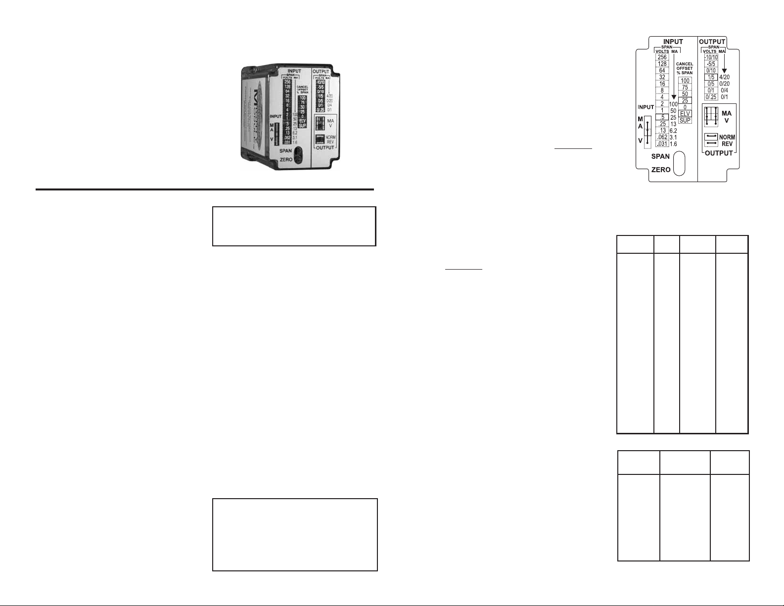
Figure 1 illustrates the range select jumper
positions.
1. Place the left-side INPUT jumper in its
MM4380A
DC INPUT
FIELD-RANGEABLE
ISOLATED TRANSMITTER
upper (MA) position for DC current
inputs or its lower (V)position for DC voltage
inputs.
2. Place the INPUT SPAN jumper at the next
position higher than the desired span. The
labeled valuesrepresent the maximum
achievable span achievable span for each
position. For example, the position marked
2 VOLTS/100 MA allows span to be
adjusted from 1 to 2 volts and from 50 to
DESCRIPTION
The MM4380A provides a DC output proportional
to a DC input. The output is fully isolated from
input, line power and ground. The unit is useful
in eliminating ground loops and common mode
signals.
Input and output ranges are fully user-settable.
Each may be voltage or current, with or without
offset. The output response may be normal or
reverse-acting. A fully-labeled set of jumpers
selects the input and output ranges. The
MM4380A is identical in size, and fully
interchangeable with, fixed-range modules such
as the MM4300.
The MM4380A includes filtering and conditioning
to reduce susceptibility to transients and noisy
operations. It utilizes a feedback VCO to develop
a pulse train with a duty cycle proportional to the
input signal amplitude. This pulse train is coupled
through a pulse transformer to the output circuitry,
where the duty cycle data is converted to a
proportional DC output level.
OPTIONS
DC Power
Inverter isolated 12 or 24 VDC power
U All circuit boards conformal coated for pro-
tection against moisture.
CONTROLS
Two controls, ZERO and SPAN, are accessible
through holes at the top of the MM4380A’s
cover. These controls allow precise calibration
to any selected range.
Range select jumpers, located at the top of the
module, are accessed by removing the cover.
The use of these jumpers is described under the
SELECTING THE RANGE SETTINGS section.
CALIBRATION
CAUTION: BE SURE ALL RANGE SELECT
JUMPERS ARE SET TO THEIR PROPER
POSITIONS BEFORE APPLYING INPUT OR
POWER.
The MM4380A is supplied calibrated for 4/20
mA input and 4/20 mA output unless otherwise
specified on your order.
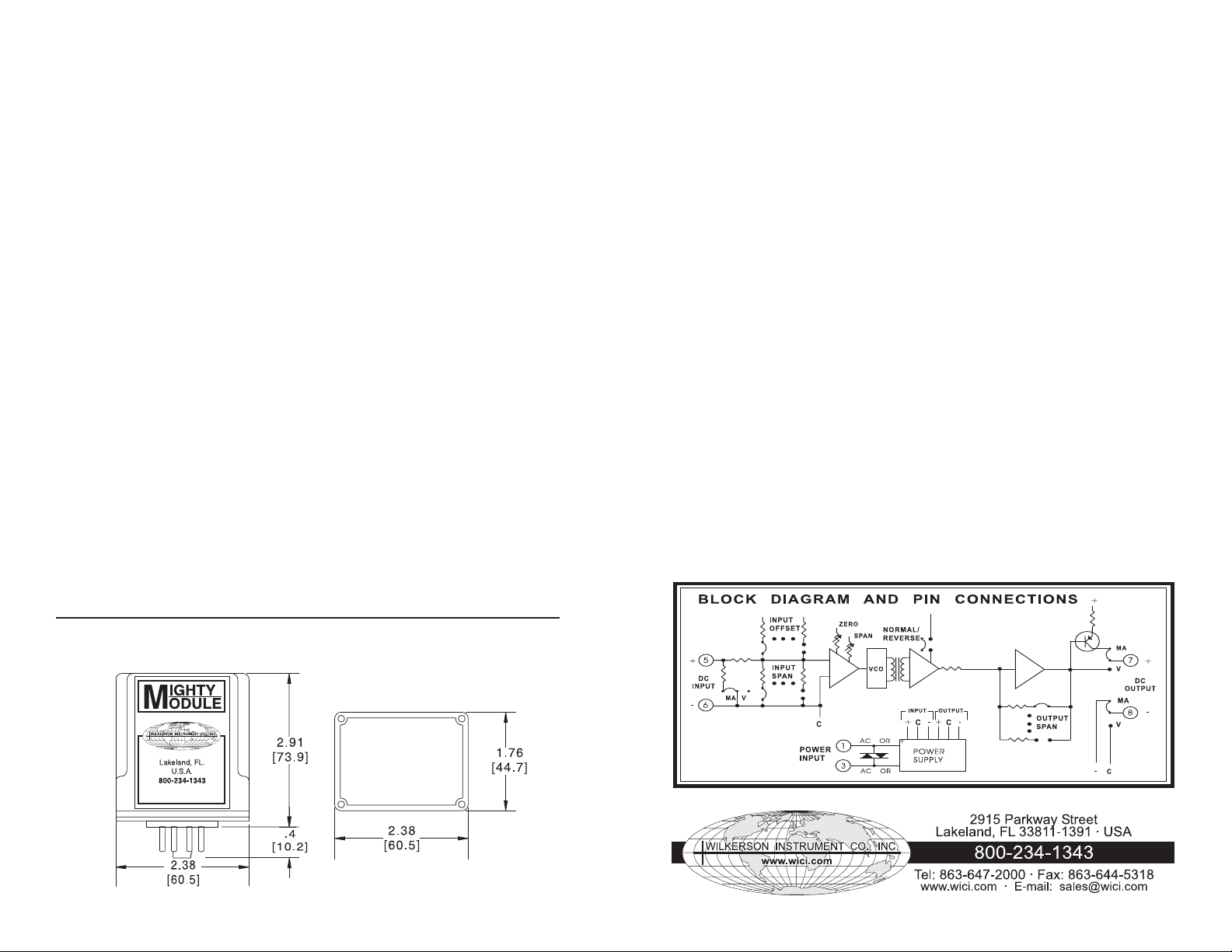
Refer to the instrument’s label to determine its
supply voltage. Check that all range select
jumpers are properly set for your input and
output range. Refer to the BLOCK DIAGRAM
AND PIN CONNECTIONS for connections.
Connect a precision DC voltage or current
source to the input. Connect a precision DC
voltage or current meter to the output. Set the
input source to the low-end value and adjust
the ZERO control for the proper low-end output.
(Adjust for full-scale output if the REVERSEACTING mode is selected.)Increase the input
to its full-scale value and adjust the SPAN
control for full-scale output (low-end output if
REVERSE-ACTING). Repeat until both
readings are correct.
SELECTING THE RANGE SETTINGS
Unplug the module and unscrew the four screws
at the corner of the base to remove the cover.
Tables 1 and 2 list typical input and output
range settings. If your range is not listed, set
the range select jumpers as follows:
CAUTION: The MM4380A’s circuitry is
precise, sensitive and closely spaced.
Circuit board contamination can lead to
errors and instability especially at high
humidities. Handle all circuit boards by their
edges only, or wear clean gloves, to avoid
contamination.
100 milliamperes.
Remember: SPAN is the difference between
full-scale and the low end. For example, a -10/
+10 V input range has a span of 20 volts, 4/20
mA has a span of 16 mA.
3. The INPUT CANCEL OFFSET % SPAN
jumper positions are labeled as percent of
maximumspan. For example, for a range
of +5/+10 V (span = 5 V), the 8 volt span
position will be used. The 5 volt input offset
is 62.5% of the 8 volt maximum span.
Place the jumper in the position nearest the
desired offset. In the above example either the
50% or the 75% positions could be used.
4. Place the ELV/SUP jumper in the ELV
(elevated)positions for positive input off
sets, SUP (suppressed) for negative off
sets. In the above example ELV would be
used.
5. Place the OUTPUT NORM/REV jumper in
the NORM (normal) position for standard
operation,REV (reverse) for reverse-act ing
(output decreases as input increases).
6. Place the OUTPUT MA/V jumpers in their
upper (MA) positions for DC current out
puts or their lower (V) positions for DC
voltage outputs. The jumpers should be
positioned vertically, not horizontally.
7. The OUTPUT SPAN jumper selects certain specific ranges, not a continuous range
of adjustments. Place the jumper at your
desired range.
8. Replace the cover, positioned so that the
holes in the top line up with the ZERO and
SPAN controls.
9. Apply power and calibrate per CALIBRATION, above.
Must be positioned vertically
Table 1. Typical Input Range Settings
INPUT SPAN CANCEL
RANGE INPUT VOLTS/MA OFFSET
0/15 mV V .031/1.6 0 ELV
0/100 mV V .13/6.2 0 ELV
0/500 mV V .5/25 0 ELV
0/1 V V 1/50 0 ELV
0/5 V V 8 0 ELV
0/10 V V 16 0 ELV
0/20 V V 32 0 ELV
0/50 V V 64 0 ELV
0/100 V V 128 0 ELV
0/200 V V 256 0 ELV
1/5 V V 4 25 ELV
-1/+1 V V 2 50 SUP
-5/+5 V V 16 50 SUP
-5/+15 V V 32 25 SUP
-10/+10 V V 32 50 SUP
0/1 mA MA .031/1.6 0 ELV
0/10 mA MA .25/13 0 ELV
0/20 mA MA .5/25 0 ELV
0/50 mA MA 1/50 0 ELV
0/100 mA MA 2/100 0 ELV
4/20 mA MA .5/25 25 ELV
10/50 mA MA 1/50 25 ELV
-10/+10 mA MA .5/25 50 SUP
-50/+50 mA MA 2/100 50 SUP
Table 2. Output Range Settings
OUTPUT SPAN
RANGE VOLTS/MA MA/V
0/250 V 0/.25 V V
0/1 V 0/1 V V
0/5 V 0/5 V V
1/5 V 1/5 V V
0/10 V 0/10 V V
-5/+5 V -5/5V V
-10/+10 V -10/10 V V
0/1 mA 0/1 mA MA
0/4 mA 0/4 mA MA
0/20 mA 0/20 mA MA
4/20 mA 4/20 mA MA
Figure 1
MA & V jumpers
1 2
REVERSE-ACTING TRANSMITTER
Use the same settings as normal action, but set
the NORM/REV jumper to REV.
Example:
For 4 to 20 mA output with 20 to 4 mA input, or
for 20 to 4 mA output with 4 to 20 mA input, use
the settings for 4/20 mA input and 4/20 mA
output with the jumper set to REV.
NEGATIVE INPUTS
1. The easiest way to accommodate nega-
tive inputs is to simply reverse the connections to the (+) and (-) inputs (5 and 6). If
this is not possible, use the following
method.
2. LO to HI output from 0 to -V input is the
sameas HI to LO output from -V to 0 input.
Select the desired output range. Set up the
INPUT jumpers for a range from minus full
scale to zero. Select REVERSE ACTING
mode.
Example:
4/20 mA output from 0/-10 V input.
(Same as 20/4 mA output from -10/0 V input.
a. Input Jumpers: Place MA/V on V (volts).
Place SPAN on 16. Place CANCEL OFF
SET % SPAN on 50. Place ELV/SUP on
SUP (suppressed).
b. Output: Place SPAN on 4/20 mA. Place
MA/V on MA (milliampere). Place NORM/
REV on REV (reverse).
c. Adjust ZERO for 20 mA output at -10 V
input. Adjust SPAN for 4 mA output at 0 V
input. Repeat until both are correct.
NEGATIVE OUTPUTS
1. To provide negative outputs simply
reverse the connections to the (+) and (-)
outputs (7 and 8).
MOUNTING
The module is designed to plug into a
standard 8-pin relay socket. (MP008) is a
molded plastic socket suitable for mounting
on a flat surface or snap into a 2 ¾ inch
wide PVC track (TRK48).
A spring hold-down clip (CLP1) is available
for installation where vibration may be a
problem.
A DIN rail mounted socket (DMP008) is
available for 35mm symmetrical DIN rail.
A Killark HK Series explosion-proof housing
with dome and 8-pin socket is available
(HKB-HK2D-8).
WARRANTY
The Field Rangeable Series of products
carry a limited permanent warranty. In the
event of a failure due to defective material
or workmanship, the unit will be repaired or
replaced at no charge.
SPECIFICATIONS
INPUT RANGE (User-Settable)
Limits
any voltage between -250 and +250 VDC
any current between -100 and +100 mAdc
Span
any voltage span from 15 mV to 250 VDC
any current span from 0.8 to 100 mAdc
Offset
can cancel any input offset between -110%
and +110% of span
INPUT IMPEDANCE
Voltage
1 megohm
Current
20 ohms
OUTPUT RANGE (User-Settable)
Voltage Current
0/.25 V 0/1 mA
0/1 V 0/4 mA
0/5 V 0/20 mA
1/5 V 4/20 mA
0/10 V
-5/+5 V
-10/+10 V
OUTPUT LOAD
Voltage
10 mA max (1 kilohm at 10 V)
Current
24 V compliance
(1200 ohms max. at 20 mA)
OUTPUT RESPONSE (User-Settable)
normal or reverse-acting
(example 10 to 0 VDC)
RESPONSE TIME
<100 ms
OUTPUT RIPPLE (peak-to-peak)
<0.1% of span
ACCURACY
±0.1% of span (exclusive of user-supplied
calibration instruments
LINEARITY
±0.05% of span
COMMON MODE REJECTION
120 dB, DC to 60 Hz
ISOLATION, OUTPUT/INPUT
>500 megohms
BREAKDOWN, OUTPUT/INPUT
>1000 VAC rms
BREAKDOWN, POWER/CIRCUITRY
>1500 VAC rms
OPERATING TEMPERATURE
14°F to 140°F (-10°C to 60°C)
TEMPERATURE STABILITY
±(0.02% of span + 2 µV)/°C max
POWER (2.5 W max)
115 VAC ±10%, 50 or 60 Hz
230 VAC ±10%, 50 or 60 Hz
(DC Power Option)
12 VDC (limits 10 VDC to 15 VDC)
24 VDC (limits 21 VDC to 32 VDC)
CASE DIMENSIONS INCHES [mm]
Specifications are subject to change without notice. ©2007 Wilkerson Instrument Co., Inc. DWG #W102457B 3/07
3 4
 Loading...