

Page 1
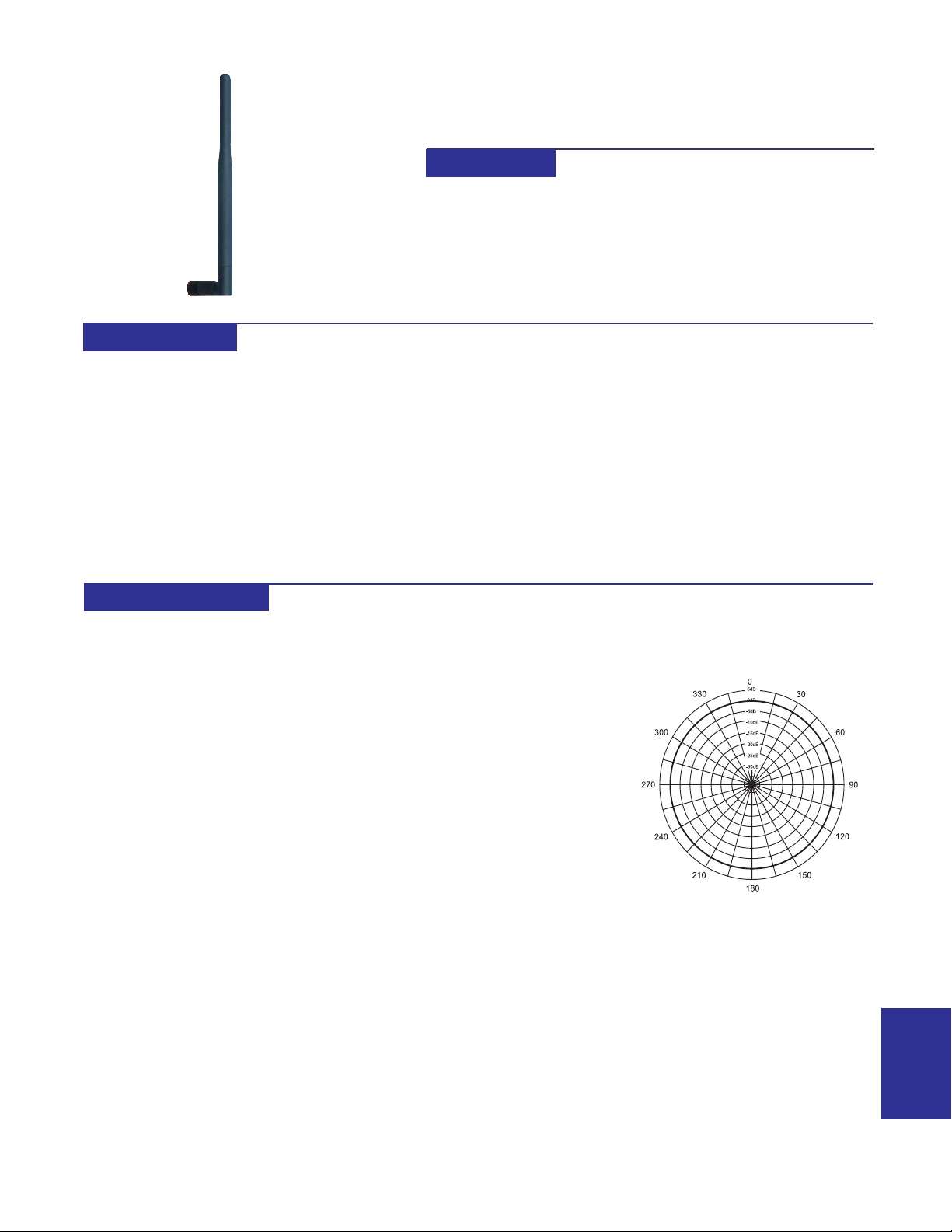
DESCRIPTION
Vertical omnidirectional antennas
radiate in a pattern similar to a
horizontal doughnut. Their gain is less
than that of a yagi antenna which
concentrates radiation in a single
direction. This reduced gain limits the
effective range of the omnidirectional
antenna, but proves effective when
directivity is not desired.
Omnidirectional antennas are useful in
short range applications where their
4008
2.1 dBi GAIN
915MHz BAND 1/2 WAVE DIPOLE ANTENNA
FEATURES
· Indoor Mounting
· Mount Directly on Product or on Electrical Housing
With Optional Cable
· Lightweight
· Range to 3000ft
use eliminates the need for antenna
alignment. Omnidirectional antennas
are also useful on the control end of a
polling system.
When an omnidirectional antenna is
used on the control end of a polling
system, a yagi can be used on each
slave unit for maximum gain and
reduction in possible interference due
to the front to back ratio gain reduction
of the yagi antenna.
The 4008 antenna swivels 90° at the
base to allow the antenna to remain
vertical with the base mounted either
vertically or horizontally .
Designed for indoor mounting, this 7"
whip offers flexibility in mounting and
dependable performance for short
range systems.
SPECIFICATIONS
ELECTRICAL
GAIN
2.1dBi
FREQUENCY
900-928MHz
VSWR
<2:1
IMPEDANCE
50 ohms
CONNECTOR
Reverse Polarity SMA Male
Brass With Nickle and Gold
Plating
MECHANICAL
RADIA TOR
Spring SS Wire
WHIP
Polyurethene (Black)
SWIVEL MECHANISM
Polycarbonate (Black)
DIAMETER
0.5"
LENGTH
7"
WEIGHT
0.7 Ounces.
MOUNTING
Direct Connect to Product
or Remote Mount With Optional
Extension Cable
VERTICAL PATTERN
ANTENNAS
27
Page 2
DESCRIPTION
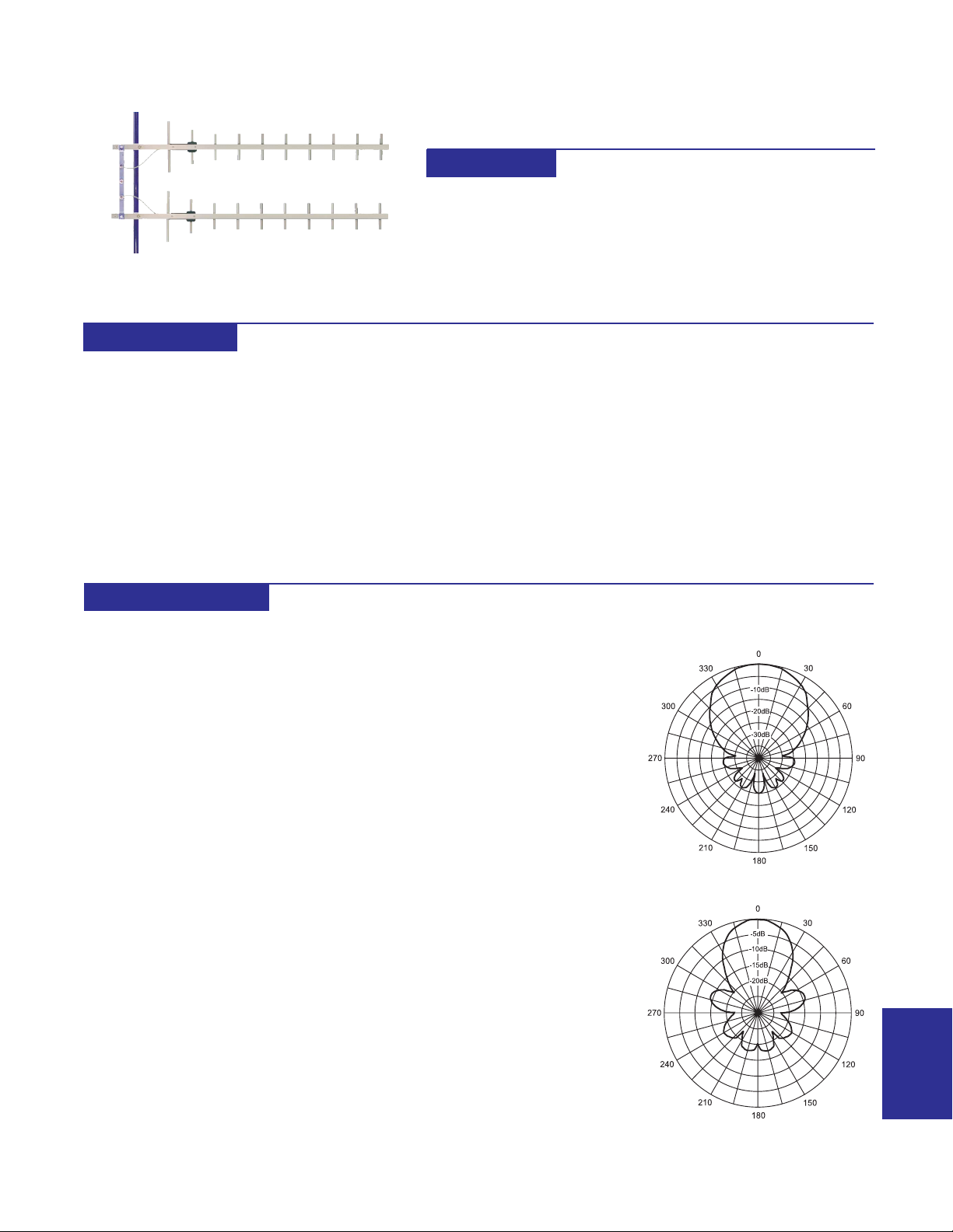
4152
17 dBi GAIN
915MHz BAND DUAL STACKED
10 ELEMENT HEAVY DUTY YAGI
FEATURES
· High Performance
· Rugged
· Weatherproof
· Lightweight
· Durable
This kit includes two (2) 4025 heavy
duty yagi antennas that are
termninated with Type N male
connectors that mate with a supplied
4074 two-port coupler. The coupler
adds the output of the two antennas
and provides approximately 2X the
signal of one antenna (3dB).
A yagi antenna can be operated with
the elements mounted vertically or
horizontally , but the most common use
SPECIFICATIONS
ELECTRICAL
GAIN
17dBi
Front to Back Ratio
20dB
FREQUENCY
896-960MHz
IMPEDANCE
50 ohms
VSWR
60MHz
<1.5:1
POWER RA TING
300 watts
CONNECTOR
Type N Female On 2
Port Coupler
for industrial wireless is vertical. The
transmitting and receiving antenna
must both have the same element
polarization for satisfactory operation.
A large loss in signal is experienced
when the elements are crossed
polarized.
When a vertical omnidirectional
antenna is used on the control end of
a polling system, a yagi can be used
on each slave unit for maximum gain
MECHANICAL
MA TERIAL
1" aluminum U channel boom
3/8" solid elements
FINISH
UV inhibited polyester coat
LENGTH
48"
WEIGHT
8 lbs.
MOUNT
Stainless Hardware for
23/8" mast
FLA T PLA TE AREA
WIND RA TING
WIND LOAD
2
.998 ft
125 MPH
67.4 lbs.
front to back ratio gain reduction.
These heavy duty yagi antennas are
constructed of 1" aluminum U channel
with 3/8" solid elements. All exposed
areas are coated with UV polyester.
The balun assembly is filled and sealed
with elastomeric thermoplastic.
The output of the 4074 two-port coupler
is a T ype N Female connector .
HORIZONTAL PATTERN
VERTICAL PATTERN
ANTENNAS
45
Page 3
DESCRIPTION
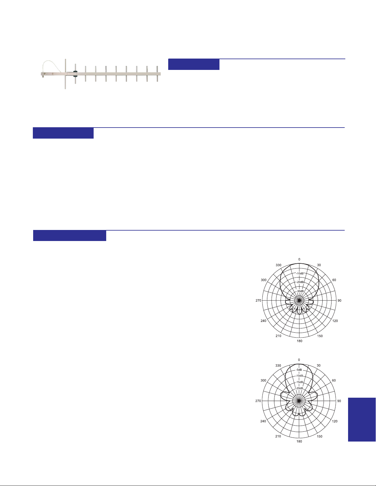
4025
14 dBi GAIN
915MHz BAND 10 ELEMENT HEAVY DUTY YAGI
FEATURES
· Rugged and Weatherproof
· Lightweight Aluminum
· SS Mounting Hardware Included
· Wind Survival to 125 MPH
Y agi antennas achieve more gain than
vertical antennas by concentrating
radiation in a single direction. Their
reduced gain from the back end helps
keep other signals from interfering with
normal operation. The front to back
ratio is an important characteristic of
a yagi antenna.
A yagi antenna can be operated with
the elements mounted vertically or
horizontally , but the most common use
SPECIFICATIONS
ELECTRICAL
GAIN
14dBi
Front to Back Ratio
20dB
FREQUENCY
900-930MHz
IMPEDANCE
50 ohms
VSWR
<2:1
VERT BEAMWIDTH
45°
HORIZ BEAM WIDTH
50°
POWER RA TING
300 watts
CONNECTOR
Type N Female on 12" T eflon
Pigtail
for industrial wireless is vertical. The
transmitting and receiving antenna
must both have the same element
polarization for satisfactory operation.
A large loss in signal is experienced
when the elements are crossed
polarized.
When a vertical omnidirectional
antenna is used on the control end of
a polling system, a yagi can be used
on each slave unit for maximum gain
MECHANICAL
MA TERIAL
1" aluminum U channel boom
3/8" solid elements
FINISH
UV inhibited polyester coat
LENGTH
48"
WEIGHT
<4 lbs.
MOUNT
Stainless Hardware for
23/8" mast
FLA T PLA TE AREA
WIND RA TING
WIND LOAD
2
.265 ft
125 MPH
15.9 lbs.
and reduction in interference due to the
front to back ratio gain reduction.
These heavy duty yagi antennas are
constructed of 1" aluminum U channel
with 3/8" solid elements. All exposed
areas are coated with UV polyester.
The balun assembly is filled and sealed
with elastomeric thermoplastic.
The connector is a T ype N Female on
a 12" teflon pigtail cable.
HORIZONTAL PATTERN
VERTICAL PATTERN
ANTENNAS
43
Page 4
DESCRIPTION
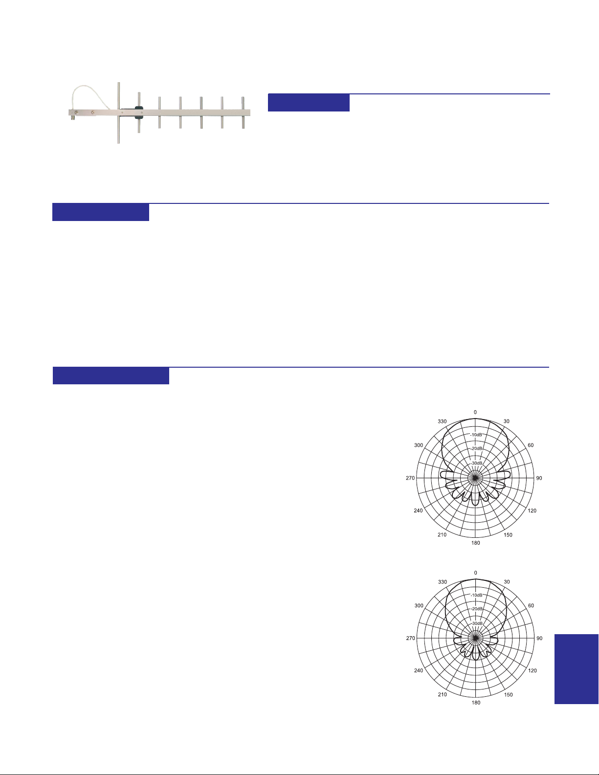
4079
12 dBi GAIN
915MHz BAND 7 ELEMENT HEAVY DUTY YAGI
FEATURES
· Rugged and Weatherproof
· Lightweight Aluminum
· SS Mounting Hardware Included
· Wind Survival to 125 MPH
Y agi antennas achieve more gain than
vertical antennas by concentrating
radiation in a single direction. Their
reduced gain from the back end helps
keep other signals from interfering with
normal operation. The front to back
ratio is an important characteristic of
a yagi antenna.
A yagi antenna can be operated with
the elements mounted vertically or
horizontally , but the most common use
SPECIFICATIONS
ELECTRICAL
GAIN
1 1dBi
Front to Back Ratio
20dB
FREQUENCY
900-930MHz
IMPEDANCE
50 ohms
VSWR
<2:1
VERT BEAMWIDTH
50°
HORIZ BEAM WIDTH
55°
POWER RA TING
300 watts
CONNECTOR
Type N Female on 12" T eflon
Pigtail
for industrial wireless is vertical. The
transmitting and receiving antenna
must both have the same element
polarization for satisfactory operation.
A large loss in signal is experienced
when the elements are crossed
polarized.
When a vertical omnidirectional
antenna is used on the control end of
a polling system, a yagi can be used
on each slave unit for maximum gain
MECHANICAL
MA TERIAL
1" aluminum U channel boom
3/8" solid elements
FINISH
UV inhibited polyester coat
LENGTH
26"
WEIGHT
<4 lbs.
MOUNT
Stainless Hardware for
23/8" mast
FLA T PLA TE AREA
WIND RA TING
WIND LOAD
2
.265 ft
125 MPH
15.9 lbs.
and reduction in interference due to the
front to back ratio gain reduction.
These heavy duty yagi antennas are
constructed of 1" aluminum U channel
with 3/8" solid elements. All exposed
areas are coated with UV polyester.
The balun assembly is filled and sealed
with elastomeric thermoplastic.
The connector is a T ype N Female on
a 12" teflon pigtail cable..
HORIZONTAL PATTERN
VERTICAL PATTERN
ANTENNAS
41
Page 5
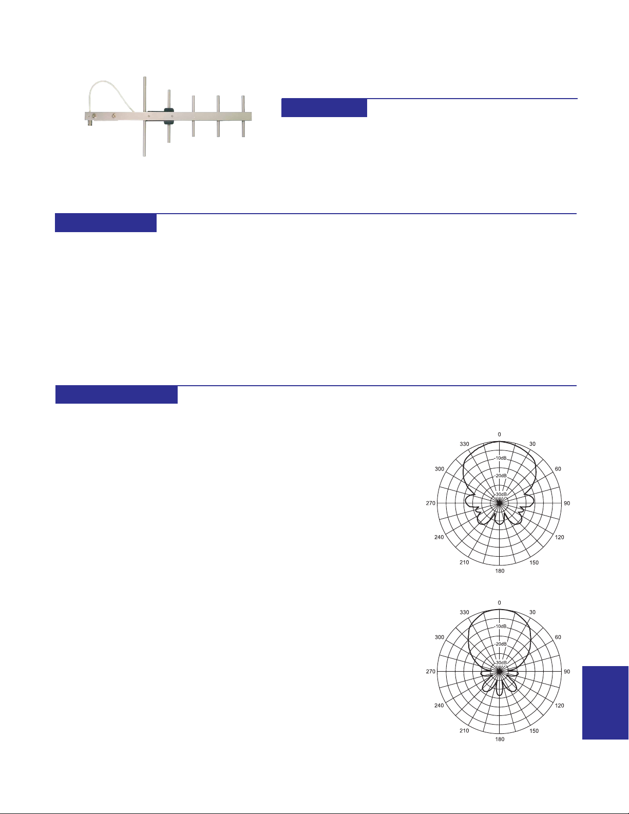
DESCRIPTION
4078
11 dBi GAIN
915MHz BAND 5 ELEMENT HEAVY DUTY YAGI
FEATURES
· Rugged and Weatherproof
· Lightweight Aluminum
· SS Mounting Hardware Included
· Wind Survival to 125 MPH
Y agi antennas achieve more gain than
vertical antennas by concentrating
radiation in a single direction. Their
reduced gain from the back end helps
keep other signals from interfering with
normal operation. The front to back
ratio is an important characteristic of
a yagi antenna.
A yagi antenna can be operated with
the elements mounted vertically or
horizontally , but the most common use
SPECIFICATIONS
ELECTRICAL
GAIN
1 1dBi
Front to Back Ratio
18dB
FREQUENCY
866-960MHz
IMPEDANCE
50 ohms
VSWR
<2:1
VERT BEAM WIDTH
55°
HORIZ BEAM WIDTH
65°
POWER RA TING
300 watts
CONNECTOR
Type N Female on 12" T eflon
Pigtail
for industrial wireless is vertical. The
transmitting and receiving antenna
must both have the same element
polarization for satisfactory operation.
A large loss in signal is experienced
when the elements are crossed
polarized.
When a vertical omnidirectional
antenna is used on the control end of
a polling system, a yagi can be used
on each slave unit for maximum gain
MECHANICAL
MA TERIAL
1" aluminum U channel boom
3/8" solid elements
FINISH
UV inhibited polyester coat
LENGTH
21"
WEIGHT
<4 lbs.
MOUNT
Stainless Hardware for
23/8" mast
FLA T PLA TE AREA
WIND RA TING
WIND LOAD
2
.206 ft
125 MPH
12.3 lbs.
and reduction in interference due to the
front to back ratio gain reduction.
These heavy duty yagi antennas are
constructed of 1" aluminum U channel
with 3/8" solid elements. All exposed
areas are coated with UV polyester.
The balun assembly is filled and sealed
with elastomeric thermoplastic.
The connector is a T ype N Female on
a 12" teflon pigtail cable.
HORIZONTAL PATTERN
VERTICAL PATTERN
ANTENNAS
39
Page 6
DESCRIPTION
Y agi antennas achieve more gain than
vertical antennas by concentrating
radiation in a single direction. Their
reduced gain from the back end helps
keep other signals from interfering with
normal operation. The front to back
ratio is an important characteristic of
a yagi antenna.
A yagi antenna can be operated with
the elements mounted vertically or
horizontally , but the most common use
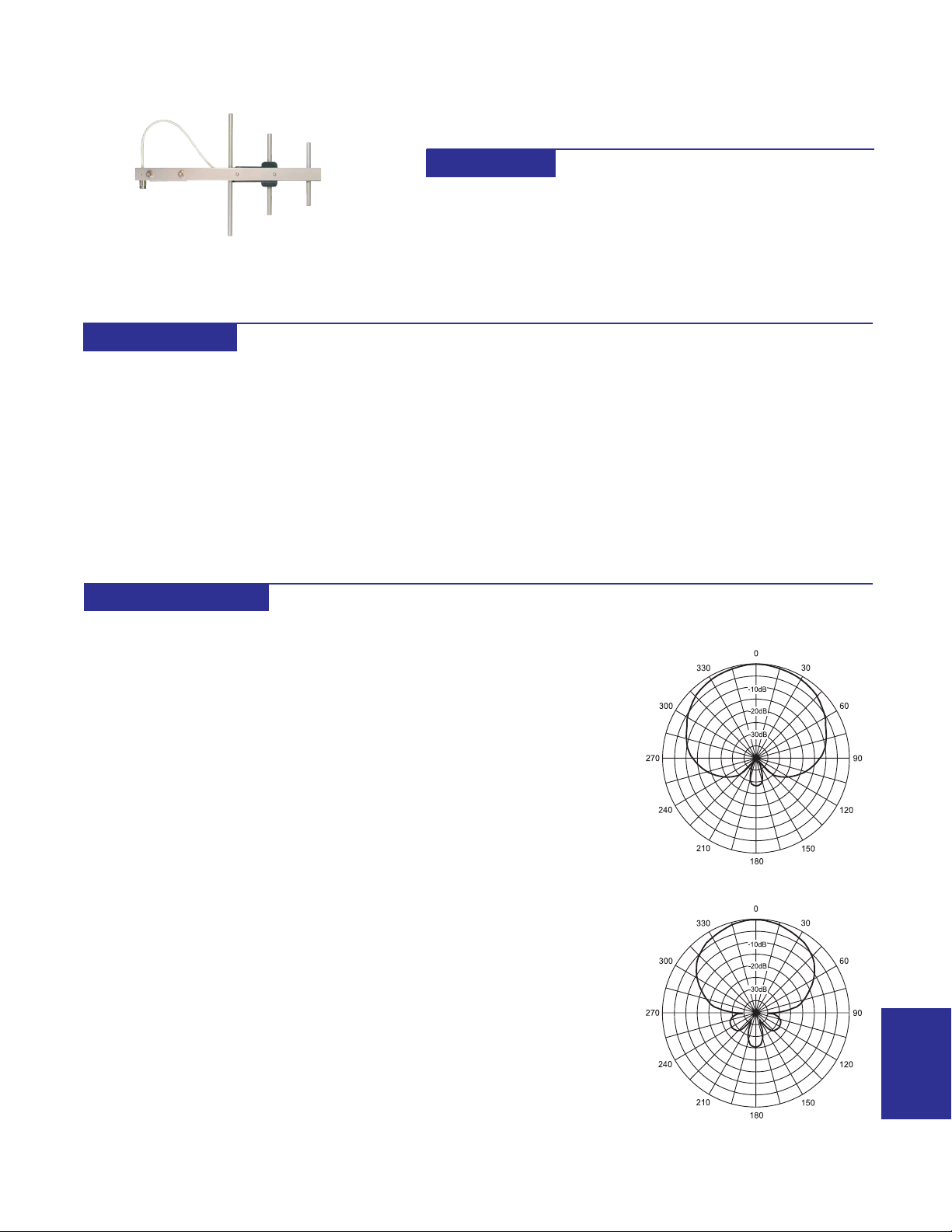
4009
8 dBi GAIN
915MHz BAND 3 ELEMENT HEAVY DUTY YAGI
FEATURES
· Rugged and Weatherproof
· Lightweight Aluminum
· SS Mounting Hardware Included
· Wind Survival to 125 MPH
for industrial wireless is vertical. The
transmitting and receiving antenna
must both have the same element
polarization for satisfactory operation.
A large loss in signal is experienced
when the elements are crossed
polarized.
When a vertical omnidirectional
antenna is used on the control end of
a polling system, a yagi can be used
on each slave unit for maximum gain
and reduction in interference due to the
front to back ratio gain reduction.
These heavy duty yagi antennas are
constructed of 1" aluminum U channel
with 3/8" solid elements. All exposed
areas are coated with UV polyester.
The balun assembly is filled and sealed
with elastomeric thermoplastic.
The connector is a T ype N Female on
a 12" teflon pigtail cable.
SPECIFICATIONS
ELECTRICAL
GAIN
8dBi
Front to Back Ratio
15dB
FREQUENCY
900-930MHz
IMPEDANCE
50 ohms
VSWR
<2:1
VERT BEAM WIDTH
70°
HORIZ BEAM WIDTH
90°
POWER RA TING
300 watts
CONNECTOR
Type N Female on 12" T eflon
Pigtail
MECHANICAL
MA TERIAL
1" aluminum U channel boom
3/8" solid elements
FINISH
UV inhibited polyester coat
LENGTH
18"
WEIGHT
<4 lbs.
MOUNT
Stainless Hardware for
23/8" mast
FLA T PLA TE AREA
WIND RA TING
WIND LOAD
2
.147 ft
125 MPH
8.8 lbs.
HORIZONTAL PATTERN
VERTICAL PATTERN
ANTENNAS
37
Page 7
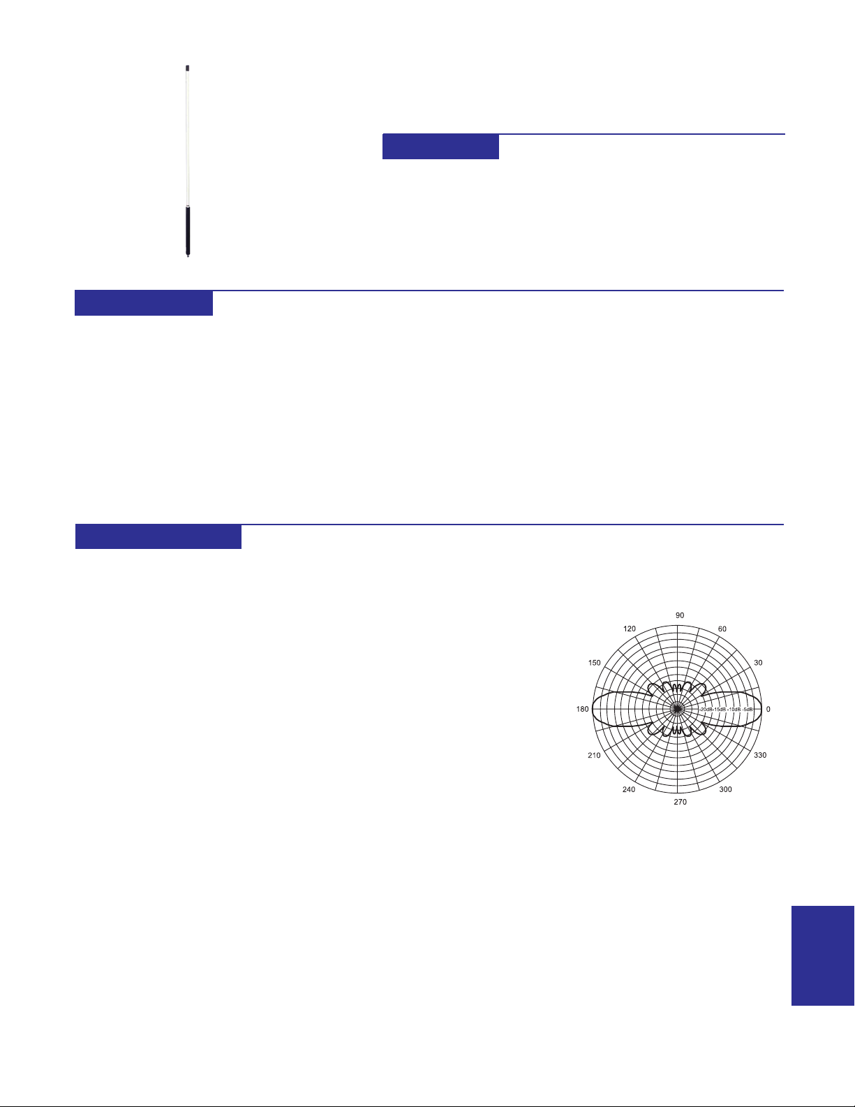
4241
8.5 dBi GAIN
915MHz BAND OMNIDIRECTIONAL ANTENNA
FEATURES
· White Fiberglass Cover
· Weatherproof For Outdoor Mounting
· Lightweight 5 Pounds
DESCRIPTION
Vertical omnidirectional antennas
radiate in a pattern similar to a
horizontal doughnut. Their gain is
proportional to their length. Increasing
the length makes the doughnut pattern
thinner and thereby increases the
power radiated horizontally.
Omnidirectional antennas are useful
in applications where their use
eliminates the need for antenna
alignment. Omnidirectional antennas
SPECIFICATIONS
ELECTRICAL
GAIN
8.5dBi
FREQUENCY
900-930MHz
IMPEDANCE
50 ohms
BANDWIDTH
30MHz
VSWR
<2.0:1
VERT BEAM WIDTH
15°
POWER RA TING
250 watts
CONNECTOR
Type N Female
are routinely used on the control end
of a polling system.
When an omnidirectional antenna is
used on the control end of a polling
system, a yagi can be used on each
slave unit for maximum gain and
reduction in possible interference due
to the front to back ratio gain reduction
of the yagi antenna.
Designed for outdoor mounting, this
60" vertical antenna offers gain and
flexibility in mounting, for ease of
installation and dependable
MECHANICAL
RADIA TOR
Copper alloy elements
RADOME
White UV inhibited fiberglass
MOUNTING SLEEVE
Heavy wall epoxy coated
aluminum
SLEEVE DIAMETER
1.35"
LENGTH
60"
WEIGHT
5 lbs.
WIND SURVIV AL
125 MPH
performance for medium to long range
systems.
The radiating structure of this antenna
is encased in a fiberglass radome to
provide protection for the copper
radiators. The fiberglass radome is
ultraviolet inhibited. The heavy wall
aluminum mounting sleeve is epoxy
coated for superior weather protection.
These antennas are lightweight at 5
lbs. and are designed to survive winds
to 125 MPH.
VERTICAL PATTERN
35
ANTENNAS
Page 8
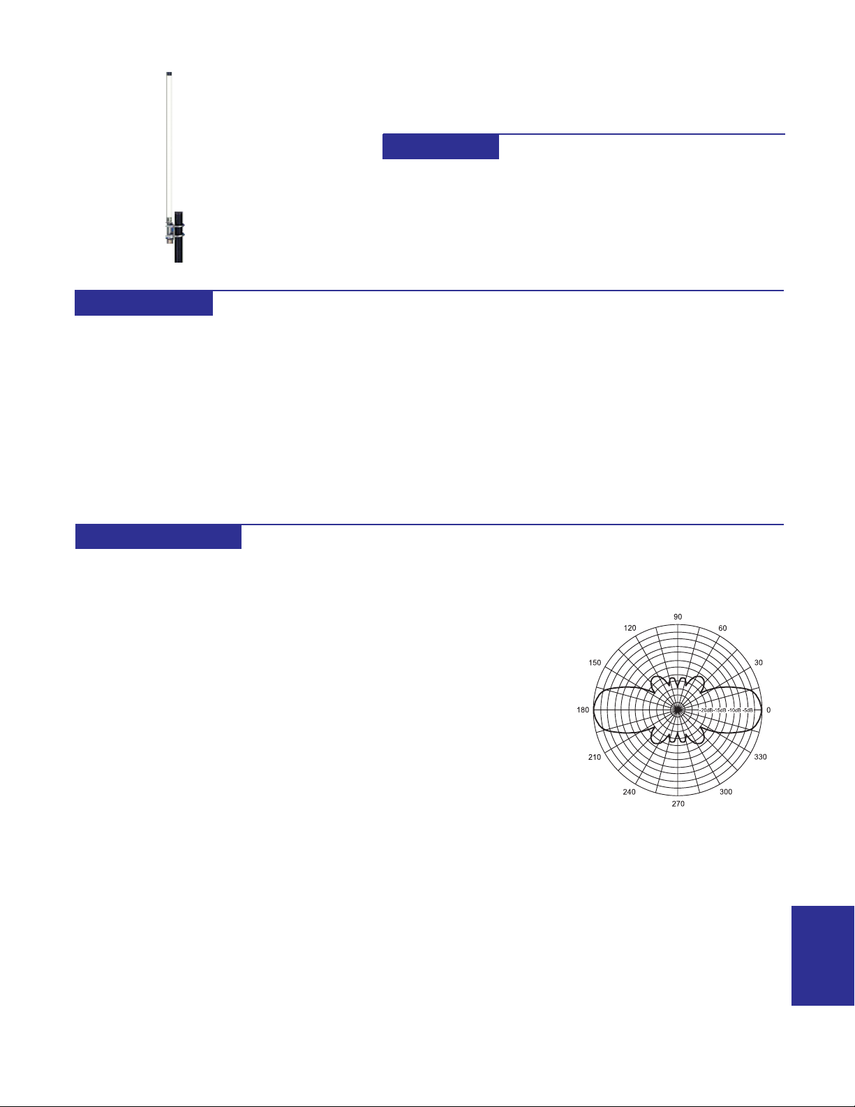
4275
6 dBi GAIN
915MHz BAND OMNIDIRECTIONAL ANTENNA
FEATURES
· White Fiberglass Cover
· Weatherproof For Outdoor Mounting
· Lightweight <3 Pounds
· Mounting Hardware Included
DESCRIPTION
Vertical omnidirectional antennas
radiate in a pattern similar to a
horizontal doughnut. Their gain is
proportional to their length. Increasing
the length makes the doughnut pattern
thinner and thereby increases the
power radiated horizontally.
Omnidirectional antennas are useful
in applications where their use
eliminates the need for antenna
alignment. Omnidirectional antennas
SPECIFICATIONS
ELECTRICAL
GAIN
6dBi
FREQUENCY
890-970MHz
IMPEDANCE
50 ohms
VSWR
<2:1
VERT BEAM WIDTH
35°
POWER RA TING
100 watts
CONNECTOR
Type N Female
are routinely used on the control end
of a polling system.
When an omnidirectional antenna is
used on the control end of a polling
system, a yagi can be used on each
slave unit for maximum gain and
reduction in possible interference due
to the front to back ratio gain reduction
of the yagi antenna.
Designed for outdoor mounting, this
27" vertical antenna offers gain and
flexibility in mounting, for ease of
MECHANICAL
RADIA TOR
Copper structure
RADOME
White UV inhibited fiberglass
SLEEVE DIAMETER
1.35"
LENGTH
27"
WEIGHT
<3 lbs.
MOUNTING
1 1/2" mast kit
(supplied)
installation and dependable
performance for medium to long range
systems.
The radiating structure of this antenna
is encased in a fiberglass radome to
provide protection for the copper
radiators. The fiberglass radome is
ultraviolet inhibited.
This antenna is supplied with
integrated mounting hardware for easy
mounting on a 1 1/2" standard mast.
VERTICAL PATTERN
33
ANTENNAS
Page 9
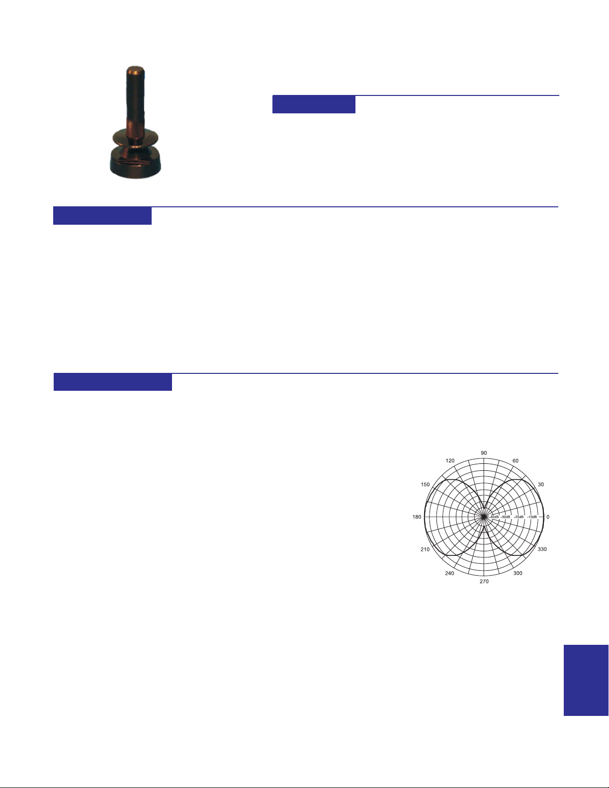
4023
2.1 dBi GAIN
915MHz / 2.4GHz DUAL BAND OMNI ANTENNA
FEATURES
· Dual Band 880-1200MHz / 2.3-2.6GHz
· Polyester Coated Brass Radiator
· Gold Plated Contacts
· Requires Accessory 4024 or 4044 for Mounting
DESCRIPTION
Vertical omnidirectional antennas radiate in
all directions therefore their gain is less than
that of a yagi antenna that concentrates
radiation in a single direction. This reduced
gain limits the effective range of the
omnidirectional antenna.
Omnidirectional antennas are useful in
applications where their use eliminates the
need for antenna alignment. Omnidirectional
antennas are routinely used on the control
end of a polling system.
When an omnidirectional antenna is used on
the control end of a polling system, a yagi
can be used on each slave unit for maximum
SPECIFICATIONS
ELECTRICAL
FREQUENCY RANGE:
880-1200MHz
2300-2600MHz
GAIN:
2.1dBi
VSWR:
<2:1
IMPEDANCE:
50 ohms
POWER RATING:
200 watts
gain and reduction in possible interference
due to the front to back ratio gain reduction
of the yagi antenna.
This Dual Band antenna has an ultra wide
bandwidth for the 880-1200MHz and 23002600MHz bands and provides 2.1dBi gain on
both.
The brass radiator is coated with a polyester
radome for corrosion resistance. The
contacts are gold plated for corrosion
resistance.
This antenna requires accessory 4024 or
4044 for mounting. Part 4024 is a Type N
female connector designed for bulkhead
mounting. The other end of the bulkhead
MECHANICAL
RADIATOR:
Polyester coated Brass
BASE:
ABS, Ultrasonic Brass Insert.
CONTACT:
Gold plated spring loaded
contact
LENGTH:
2 3/4"
MOUNTING:
Accessories 4024, 4044, 4045
FINISH:
Black
mount interfaces with the antenna.
Part 4044 allows the bulkhead connector
(4024) to be mounted on a right angle bracket
which has hardware to allow mounting the
antenna vertically on a vertical pipe.
To insure specified operation, this antenna
must have a conductive surface under it
when it is mounted. Mounting the antenna on
a metal electrical box provides a satisfactory
ground plane.
When mounting the antenna on a mast,
accessory 4044 provides an adequate
ground plane for 2.4GHz operation. When
used for 900MHz systems, a larger ground
plane is required (4045).
VERTICAL PATTERN
31
ANTENNAS
 Loading...