

Wilkerson Instrument DR9051R-03 Data sheet
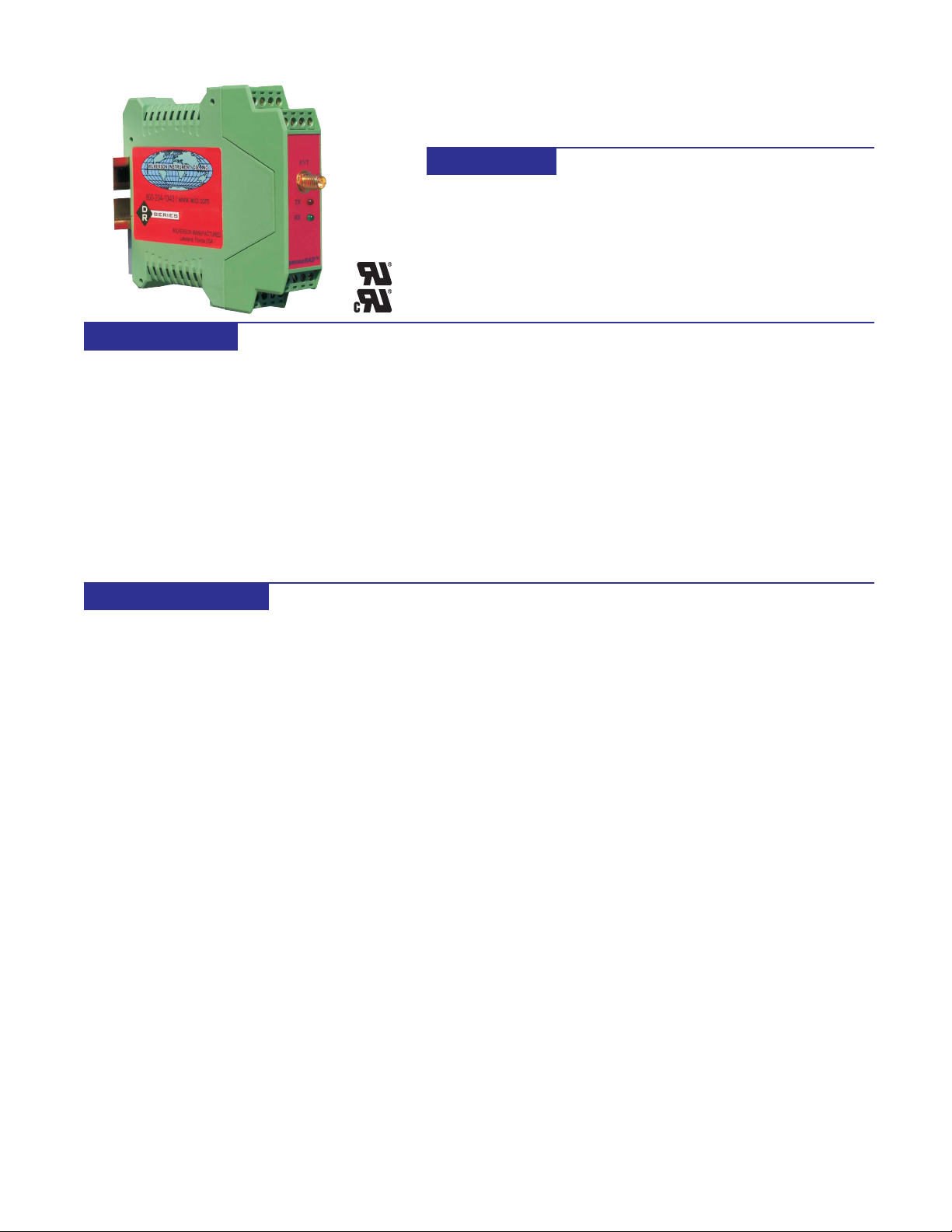
DR9051R-03
RTD INPUT POLLING TRANSMITTER
DESCRIPTION
The DR9051R is an RF transmitter that will
accept both analog and switch contact
inputs. A 12 bit A/D converter is used to
digitize the analog data. Analog data and
switch status is read when requested by the
companion DR9050 Control Unit. The DR9050
polls the DR9051R and outputs the data in
Modbus RTU format. A single DR9050 can
poll up to 247 DR9051R’s utilizing a single
Hop sequence.
The DR9051R has a repeater capability that
is useful for data monitoring in areas where
the DR9050 cannot communicate directly with
a DR9051R due to distance or obstructions
in the transmission path.
SPECIFICATIONS
FEATURES
• Direct RTD Input
• Four Digital Inputs For Contact
Closure or NPN Transistor
• Repeater Capability
• DIN Rail Mount - Steel Clip
• 10-30VDC Power
• Reverse Polarity Screw-On
SMA Antenna Connector
• 915MHz ISM* Band - 2
Versions, 14 Hop Sequences
The switch inputs require a standard contact
closure or an open collector NPN transistor.
Three radio modules are available for the
DR9051R, two 915MHz band versions with
7 Hop sequences each and a 2.4GHz band
version with 7 Hop sequences. They use
spread spectrum, frequency hopping*
technology. These choices provide 21
different Hop sequences that allow 21
systems to work in the same locale without
interfering with each other.
With proper antenna and cable selection and
a 915MHz band version radio, the DR9051R
can transmit up to 20 miles. The 2.4GHz band
version can transmit up to 10 miles.
• 2.4GHz Unlicensed Band - 1
Version, 7 Hop Sequences
• Spread Spectrum, Frequency
Hopping Technology*
• Line of Sight Range to 20 Miles
With 915MHz Band Radio
• Line of Sight Range to 10 Miles
With 2.4GHz Band Radio
• 5 Year Warranty
(1 Year on Radio Module)
• UL/cUL Recognized
The DR9051R provides isolation between
input and power source.
A 10 VDC precision power supply is built-in
and provides excitation for up to four (4) 330
ohm bridges.
Screw terminal blocks that plug into the case
allow easy wiring and removal of products.
All of the DR Series of products provide
transient protection to help eliminate damage
from lightning and from other transients
created on the power and signal leads.
INPUT
RTD
100 ° Platinum, 2 or 3 Wire
.00385 or .00392 Alpha
Range
-200 to +850°C Maximum
15°C Span Minimum
Accuracy
±0.05% of Span
Linearity
±0.05% of Span
Open Sensor:
Full Scale
Switch Input
Open Circuit Voltage
Equals Power Input
(10 to 30 VDC)
Closed Circuit Current
3 to 9 mA
RADIO
Frequency
915 MHz Band
908 or 922 MHz
2.4 GHz Band
2.4000 - 2.4835 GHz
Spread Spectrum Type
Frequency Hopping, Direct FM
I/O Data Rate Tx to Rx:
9600 bps
Range / Line of Sight
915 MHz Band - Up to 20 Mi.
2.4 GHz Band - Up to 10 Mi.
Receiver Sensitivity:
915 MHz Band
-110 dBm @ 9600 baud
2.4 GHz Band
-105 dBm @ 9600 baud
Transmitter Power:
915 MHz Band
100 mW (20 dBm)
2.4GHz Band
50 mW (17dBm)
Connector:
Reverse Polarity SMA Female
CERTIFICATIONS
RF Module
FCC Part 15.247
DR9051R-03
UL/cUL Recognized
CCOMMON MODE REJECTION
100 dB, DC to 60 Hz
OPERATING TEMPERATURE
-13°F to 167°F
-25°C to 75°C
TEMPERATURE STABILITY
±(0.01% of Span)/°C Max
POWER
10 to 30 VDC
1.5 Watts Max
* See page 56 for a comprehensive
definition.
25
DR9051R-03
Wilkerson Instrument Co., Inc. Copy and Fax to Place Order.
ORDERING
INFORMATION
Input Range
(Must be within minimum to maximum specification)
Zero Scale
Full Scale
°C °F
Alpha:
.00385 .00392
RADIO
908 MHz - Standard
922 MHz - Optional
2.4 GHz
* NOTE: This unit must be used with a DR9050 Master Control Unit.
ACCESSORIES
RP = Reverse Polarity
4073 Two Antenna Coupler, Transmit and Receive, 2-Port 900 MHz QTY _____
4051 Receive Only, 2 to 4 Antenna Coupler 4-Port 900 MHz QTY _____
4061 Receive Only, 2 to 4 Antenna Coupler 4-Port 2.4 GHz QTY _____
4062 50 Ohm Termination, For Unused Ports On P/N 4051,4061 QTY _____
4022 PSP24-024S, 24 VDC 1 Amp Power Supply QTY _____
4026 Bulkhead Connector Type N Female to Type N Female QTY _____
4011 Bulkhead Surge Protector Type N Male to Type N Female QTY _____
4035 Bulkhead Surge Protector Type N Female to Type N Female QTY _____
CBH2 2 Ft WBC195 Cable w/ RP-SMA Male & RP-SMA Female Bulkhead Connector QTY _____
CBH6 6 Ft WBC195 Cable w/ RP-SMA Male & RP-SMA Female Bulkhead Connector QTY _____
CBH10 10 Ft WBC195 Cable w/ RP-SMA Male & RP-SMA Female Bulkhead Connector QTY _____
CBH-X Custom Length WBC195 Cable w/ RP-SMA Male & RP-SMA Female Bulkhead Connector QTY _____
CPT2 2 Ft WBC195 Cable w/ RP-SMA Male & Type N Male Connector QTY _____
CPT6 6 Ft WBC195 Cable w/ RP-SMA Male & Type N Male Connector QTY _____
CPT10 10 Ft WBC195 Cable w/ RP-SMA Male & T ype N Male Connector QTY _____
CPT-X Custom Length WBC195 Cable w/ RP-SMA Male & Type N Male Connector QTY _____
For more accessories and cables, see the ACCESSORIES section of this catalog (Page 51).
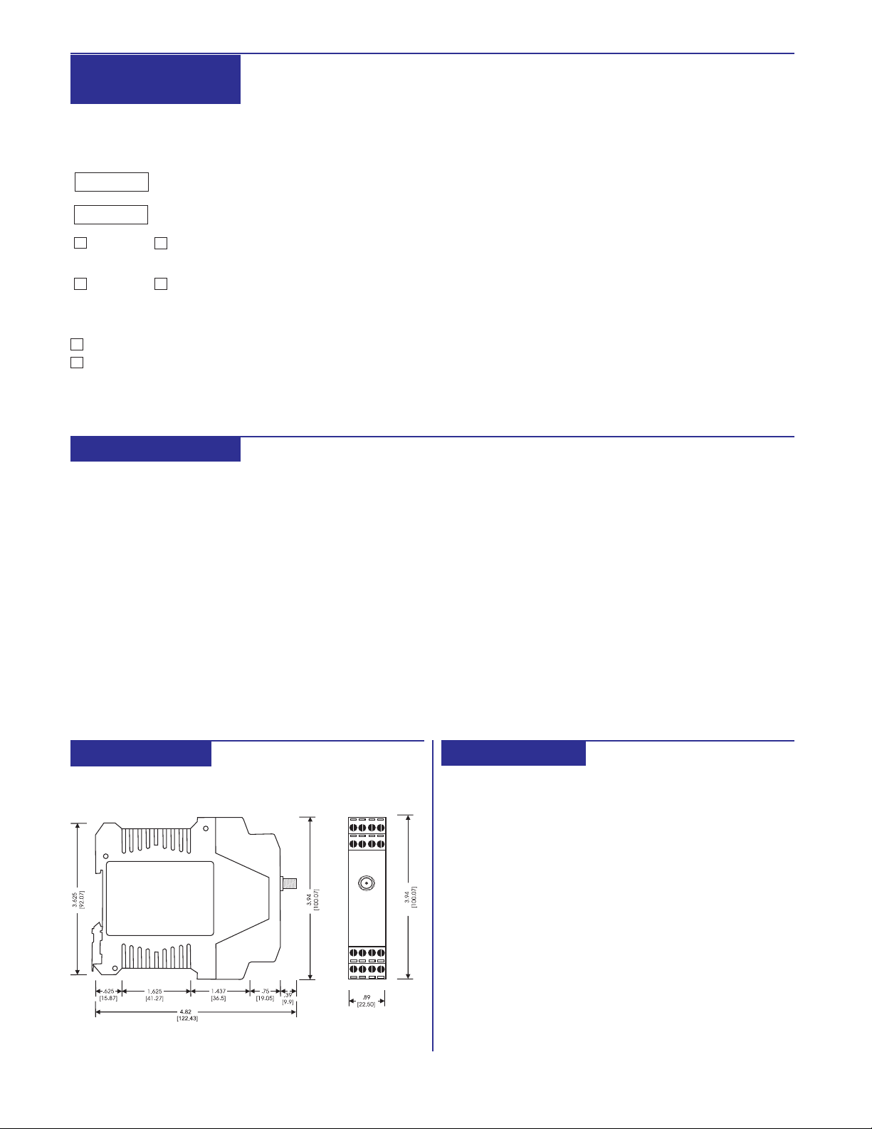
DIMENSIONS
Inches [mm]
CONNECTIONS
TERMINAL
CONNECTION
26
1
2
3
4
5
6
7
8
9
10
11
12
13
14
15
16
RTD Input +
RTD Input RTD Lead Compensation
No Connection
Switch 1 +
Switch 1 Switch 2 Switch 2 +
Switch 3 +
Switch 3 Switch 4 Switch 4 +
No Connection
No Connection
Power +
Power -
 Loading...