

Wilkerson Instrument DR9050, DR9051R Operating Manual
DR9050 / DR9051R
WIRELESS POLLING
DATA ACQUISITION SYSTEM
MODBUS RTU PROTOCOL
INSTALLA TION & OPERATION MANUAL
BASIC SYSTEM DESCRIPTION
The DR9050 / DR9051R is a polling wireless data acquisition system. A single DR9050 provides a portal which
allows a Modbus Master Controller (MMC) to interrogate from 1 to 247 DR9051R remote transmitters and report
the requested data to the MMC using the RTU protocol.
The system requires only one DR9050 and at least one DR9051R remote transmitter. The DR9051R is an RF
transmitter that will accept both analog and switch contact inputs. Analog data and switch status is transmitted
upon request to the DR9050.
A query for data sent to the DR9050 by the MMC, forces the DR9050 to broadcast an RF transmission with a
specific address of a DR9051R remote transmitter in its data packet. The DR9051R addressed receives the query
and responds with a transmission back to the DR9050. The DR9050 sends the requested data to the MMC.
The physical layout of the system must be designed so the DR9050 RF transmission can be received by all
DR9051R units in the system.
RF SYSTEM DESCRIPTION
The DR9050 and DR9051R have a plug-in RF transceiver module. Three different modules are available.
The system can be ordered as a 910 - 917MHz, 920 - 927MHz or 2.4GHz system. All three systems take advant age
of the unlicensed ISM frequency bands. Both of the 900MHz systems have a transmit power of 100mW (20dBm)
with a receive sensitivity of -1 10dBm. The 2.4GHz system has a transmit power of 50mW (17dBm) with a receive
sensitivity of -105dBm.
The communication rate between the DR9050 and DR9051R is 9600 baud. The RF modules utilize spread spectrum,
frequency hopping technology to allow reliable communications with a minimum of interference from other RF
signals.
Spread spectrum, frequency hopping indicates the transmitter and receiver have the ability to hop between
frequencies in a controlled sequence in a defined range of frequencies. The 3 modules available each have 7 hop
sequences available that hops the frequency through 25 steps in the defined frequency band. For a given module,
this allows up to 7 systems to operate in close proximity without interfering with each other. With all 3 modules
available, up to 21 systems can be operated in close proximity without interfering with each other.

REPEATER CAPABILITY
The DR9051R remote transmitter has a repeater capability that is useful for data monitoring in areas where
the DR9050 cannot communicate directly with a DR9051R due to distance or obstructions in the transmission
path.
A normal system has the DR9051R unit s and the DR9050 all set on the same hop sequence. The DR9050 transmits
the address of the DR9051R of interest. The DR9051R responds with the desired data.
A DR9051R that can communicate with the DR9050 and is also able to communicate with the obstructed DR9051R
is chosen as a Repeater. A dip switch in this DR9051R selects the Repeater mode and allows a hop sequence to
be selected with a dip switch.
The obstructed DR9051R has its system hop sequence set at a value other than the DR9050 hop sequence
(system value). The DR9051R Repeater has the same hop sequence set on the dip switch as the obstructed
DR9051R has set in its memory.
When the DR9050 polls the obstructed DR9051R address, the DR9051R in the Repeater mode will rebroadcast
the poll data on the hop sequence set on its dip switch.
The obstructed DR9051R will receive the addressed query from the Repeater and respond by transmitting the
data. The DR9051R Repeater will receive the data, change its hop sequence to the system value and transmit the
data which will be received by the DR9050.
The total number of Repeaters allowed in a system is large. Each Repeater has 6 hop sequences it can use, and
also has the obstructed DR9051R’s addresses as a further selection tool.
A simple straight line application would allow 7 DR9051R’ s to be used to collect data up to over 100 miles distance.
The hop sequences would be set as shown below. This can be varied to fit the need.
DR9050 System Hop = 0
DR9051R #1 Hop = 0 - Repeater Hop = 1 DR9051R #5 Hop = 4 - Repeater Hop = 5
DR9051R #2 Hop = 1 - Repeater Hop = 2 DR9051R #6 Hop = 5 - Repeater Hop = 6
DR9051R #3 Hop = 2 - Repeater Hop = 3 DR9051R #7 Hop = 6
DR9051R #4 Hop = 3 - Repeater Hop = 4
This system could be expanded by repeating the above system. Once a DR9051R is out of the range of a DR9051R
with the same hop sequences, the hop sequences can be repeated.
In the first example, the last DR9051R in the group would use hop sequence 6 to receive
and transmit. It could be set as a Repeater and retransmit on hop 0. Another string of 7 unit s could be used. This
expansion process could be repeated until 247 DR9051R’s are in the system.
A DR9051R Repeater changes it s hop value to it s system value as soon as it receives a response for the repeater
query. If no response is received, the DR9051R times out and switches from its repeater hop value to its system
hop value.
Utilizing the DR9050 Setup Software, system hop sequences can be ascertained and changed for the DR9050
and all of the DR9051R units in the system. The dip switch repeater hop value must be manually changed at the
DR9051R.
ANTENNAS & COAXIAL CABLES
Reliable operation of a wireless system requires adequate signal strength from the transmitters arrive at the receivers.
To insure adequate signal strength, consideration must be given to the site layout, the antennas, and the coaxial
cable used.
2
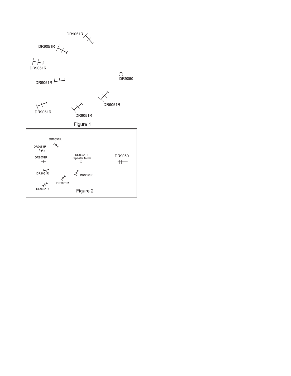
Site Layout
A polling system typically locates the DR9050 at a control
center and the DR9051R remote transmitters at the
different sites of data collection. The antenna used on the
DR9050 is typically omnidirectional. It has a radiation
pattern like a horizontal doughnut. The antennas used on
the DR9051R’s are usually low gain directional yagi
antennas which are mounted, with the elements vertical,
pointed at the omnidirectional antenna of the DR9050. The
gain required is dependent on terrain and distances
involved. The DR9050 omnidirectional antenna is required
so all the DR9051R’s are in the radiation pattern of the
DR9050. See Fig. 1
Systems with data collection sites in close proximity can
successfully use small vertical antennas (omnidirectional)
on each DR9051R.
Different types of antennas can be used on the DR9051R’s
to meet the needs of signal strength.
If the distance between the points of data acquisition and
the DR9050 is great, a high gain antenna can be used on
the DR9050 and it communicates with a DR9051R in the
Repeater mode. The Repeater DR9051R rebroadcasts
data queries with an omnidirectional antenna. Each
DR9051R responds through low gain antennas pointed at
the Repeater DR9051R omnidirectional antenna. The
Repeater then transmits to theDR9050. See Fig. 2.
Coaxial Cables
The DR9050 and DR9051R have small RF connectors to make the connection to the antenna. The units are
usually mounted in an electrical enclosure and the coaxial cable must run from the small connector to the antenna.
A short, small diameter cable is used from the DR product s connector to a bulkhead connector mounted in the side
of the electrical enclosure. A larger diameter cable is then used to complete the connection to the antenna.
The small cable allows small bend radiuses inside the enclosure for routing convenience. The large cable from
the bulkhead connector to the antenna provides less signal loss.
A transient suppressor should be mounted at the bulkhead connector to protect the system from lightning.
3
SYSTEM CONTENTS
A system includes:
This Installation / Operation manual
DR9050 Setup Software CD
DR9050 control unit
DR9051R remote transmitters for each data collection site and stand alone repeater function
DB9 connector to 4 pin plug-in terminal block cable adapter for computer RS232 connection
CRC disable jumper (see below)
The following material must be defined and ordered
Antennas and accessories for each DR product
Coaxial cables for each DR product
Bulkhead connectors as required
Transient suppressors as required
Coaxial cable for final run to antennas
Any other accessories required for the completion of the system
The DR9050 Setup software requires a computer (PC or laptop) with an RS232 serial port, an RS232 cable and
Windows 98, Windows XP, or Windows Vista operating system.
If a USB port is the only available port, a USB to RS232 adapter can be used to mate the computer to the DR9050.
See PN4420 in the Wilkerson Instrument Company Wireless Catalog
The RS232 cable connects the computer to the DR9050 via the DB9 to plug-in terminal cable adapter. A jumper
(supplied) is required for 2 of the DR9050 terminals. This jumper disables the Cyclical Redundancy Check (CRC)
error checking used by the Modbus RTU protocol.
SYSTEM SETUP
Before the DR9050 can be used, it must have system addresses assigned to each DR9051R in the system. Each
DR9051R is assigned a unit ID at the factory . The unit ID is on the DR9051R label and on it s printed circuit board.
A list of the unit ID (nnn, nnn, nnn) and physical location (or application) of each DR9051R should be compiled to
help with the assignment of the system addresses. A worksheet can be printed from the Address Editor in the
DR9050 Setup software.
The Address Editor allows a System Address ( 1 - 247) to be assigned to each DR9051R. It also provides space
for notes or comments for each system address. The address data can be saved for a project.
The Wilkerson supplied software is an editor that simplifies the assignment of system addresses to each DR9051R
in the system. Install the software and read the Help files for detailed help on the process.
The Setup software also allows data to be read from each DR9051R in the system. System hop numbers can also
be changed in the entire system from the DR9050 site.
CONNECTING TO THE DR9050
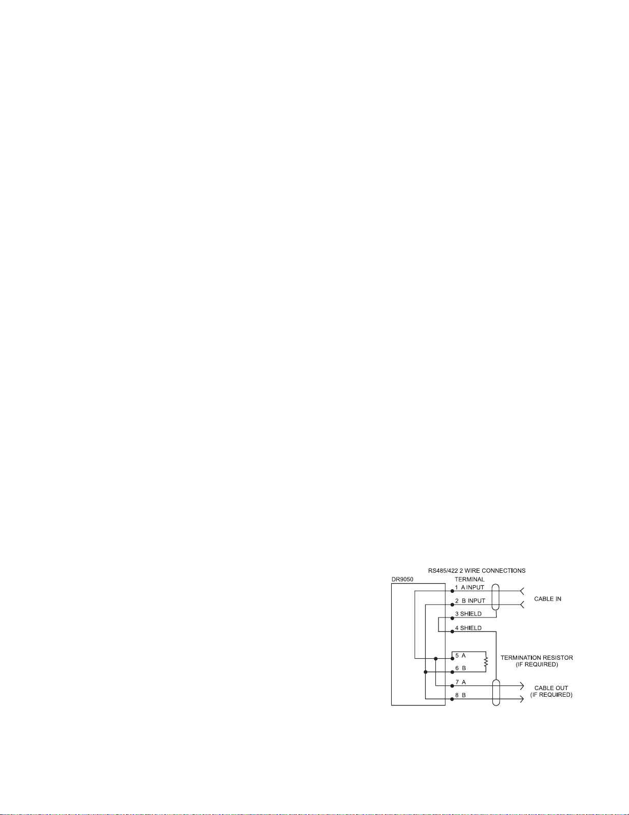
Serial Connection RS485/422
The DR9050 is a portal to 1 to 247 DR9051R remote transmitters. It
only responds to queries received from a Modbus Master Controller
(MMC) via the RS485/422 serial connections.
T o query the DR9050 for data, a MMC must be connected to the RS485/
422 terminals. The MMC can be a PLC, PC, Data logger, DCS, or any
device that is capable of acting as a Modbus RTU master controller.
Use the controller’s installation instructions along with the terminal
locations identified in Figure 3 to determine the proper wiring of the
communication cable.
The DR9050 can be part of a system that includes wireless data
acquisition as well as hard wired instruments connected to the RS485/
422 transmission line in parallel with the DR9050.
For MODBUS® RTU operation, the DR9050 requires serial communications of 9600 baud, 1 start bit, 8 data bits,
no parity, and 2 stop bits.
4
 Loading...