

Wilkerson Instrument DR9050 Data sheet

DR9050
WIRELESS MASTER CONTROL UNIT
DESCRIPTION
The DR9050 is an RF transmitter/
receiver that is used to poll data from
companion DR9051R’s. A user Modbus
RTU Master Controller (PLC / DCS etc)
initiates a query to a Modbus address.
The DR9050 MCU determines the
correct DR9051R for this address, polls
the DR9051 and returns the requested
data. A single DR9050 can poll up to
247 DR9051R’s utilizing a single Hop
sequence.
SPECIFICATIONS
FEATURES
• Modbus RTU Input/Output
• RS485/422 Interface
• Open Architecture - Customer
Can Write Custom Software
• DIN Rail Mount - Steel Clip
• 10-30VDC Power
• Reverse Polarity Screw-On
SMA Antenna Connector
• 915MHz ISM* Band - 2
Versions, 14 Hop Sequences
The radio transmitter outputs 100mW
(21.5 dBm) in the 915 MHz unlicensed
ISM band. It uses frequency hopping,
spread spectrum* technology to allow
multiple systems to work in the same
locale without interference.
Setup software is provided to program
all the system addresses into the
DR9050. Addresses may be edited and
Hop Sequences can be changed for the
system. All setup can be done at the
DR9050 site.
• 2.4GHz Unlicensed Band - 1
Version, 7 Hop Sequences
• Spread Spectrum, Frequency
Hopping Technology*
• Line of Sight Range to 20 Miles
With 915MHz Band Radio
• Line of Sight Range to 10 Miles
With 2.4GHz Band Radio
• 5 Year Warranty
(1 Year on Radio Module)
• UL/cUL Recognized
Screw terminal blocks that plug into the
case allow easy wiring and removal of
products.
All of the DR Series of products provide
transient protection to help eliminate
damage from lightning and from other
transients created on the power and
signal leads.
RADIO
Frequency
915 MHz Band
908 or 922 MHz
2.4 GHz Band
2.4000 - 2.4835 GHz
Spread Spectrum Type
Frequency Hopping, Direct FM
I/O Data Rate Tx to Rx:
9600 bps
Range / Line of Sight
915 MHz Band - Up to 20 Mi.
2.4 GHz Band - Up to 10 Mi.
Receiver Sensitivity:
915 MHz Band
-110 dBm @ 9600 baud
2.4 GHz Band
-105 dBm @ 9600 baud
Transmitter Power:
915 MHz Band
100 mW (20 dBm)
2.4GHz Band
50 mW (17dBm)
Connector:
Reverse Polarity SMA Female
INPUT / OUTPUT
Modbus® RTU
RS485/422
Half Duplex
9600 Baud
1 Start Bit
8 Data Bits
1 Stop Bit
RS232
For Setup Software
Cable Adapter Supplied
CERTIFICATIONS
RF Module
FCC Part 15.247
DR9050
UL/cUL Recognized
OPERATING TEMPERATURE
-13°F to 167°F
-25°C to 75°C
POWER
85/230 VAC
2.0 VA Max
* See page 56 for a comprehensive
definition.
27
DR9050
Wilkerson Instrument Co., Inc. Copy and Fax to Place Order.
ORDERING
INFORMATION
RADIO
908 MHz - St andard
922 MHz - Optional
2.4 GHz
NOTE: Radio used must match DR9051 Radio
* NOTE: This unit must be used with DR9051R wireless transmitters.
ACCESSORIES
RP = Reverse Polarity
4073 Two Antenna Coupler, Transmit and Receive, 2-Port 900 MHz QTY _____
4051 Receive Only, 2 to 4 Antenna Coupler 4-Port 900 MHz QTY _____
4061 Receive Only, 2 to 4 Antenna Coupler 4-Port 2.4 GHz QTY _____
4062 50 Ohm Termination, For Unused Ports On P/N 4051,4061 QTY _____
4022 PSP24-024S, 24 VDC 1 Amp Power Supply QTY _____
4026 Bulkhead Connector Type N Female to Type N Female QTY _____
4011 Bulkhead Surge Protector Type N Male to Type N Female QTY _____
4035 Bulkhead Surge Protector Type N Female to Type N Female QTY _____
CBH2 2 Ft WBC195 Cable w/ RP-SMA Male & RP-SMA Female Bulkhead Connector QTY _____
CBH6 6 Ft WBC195 Cable w/ RP-SMA Male & RP-SMA Female Bulkhead Connector QTY _____
CBH10 10 Ft WBC195 Cable w/ RP-SMA Male & RP-SMA Female Bulkhead Connector QTY _____
CBH-X Custom Length WBC195 Cable w/ RP-SMA Male & RP-SMA Female Bulkhead Connector QTY _____
CPT2 2 Ft WBC195 Cable w/ RP-SMA Male & Type N Male Connector QTY _____
CPT6 6 Ft WBC195 Cable w/ RP-SMA Male & Type N Male Connector QTY _____
CPT10 10 Ft WBC195 Cable w/ RP-SMA Male & T ype N Male Connector QTY _____
CPT-X Custom Length WBC195 Cable w/ RP-SMA Male & Type N Male Connector QTY _____
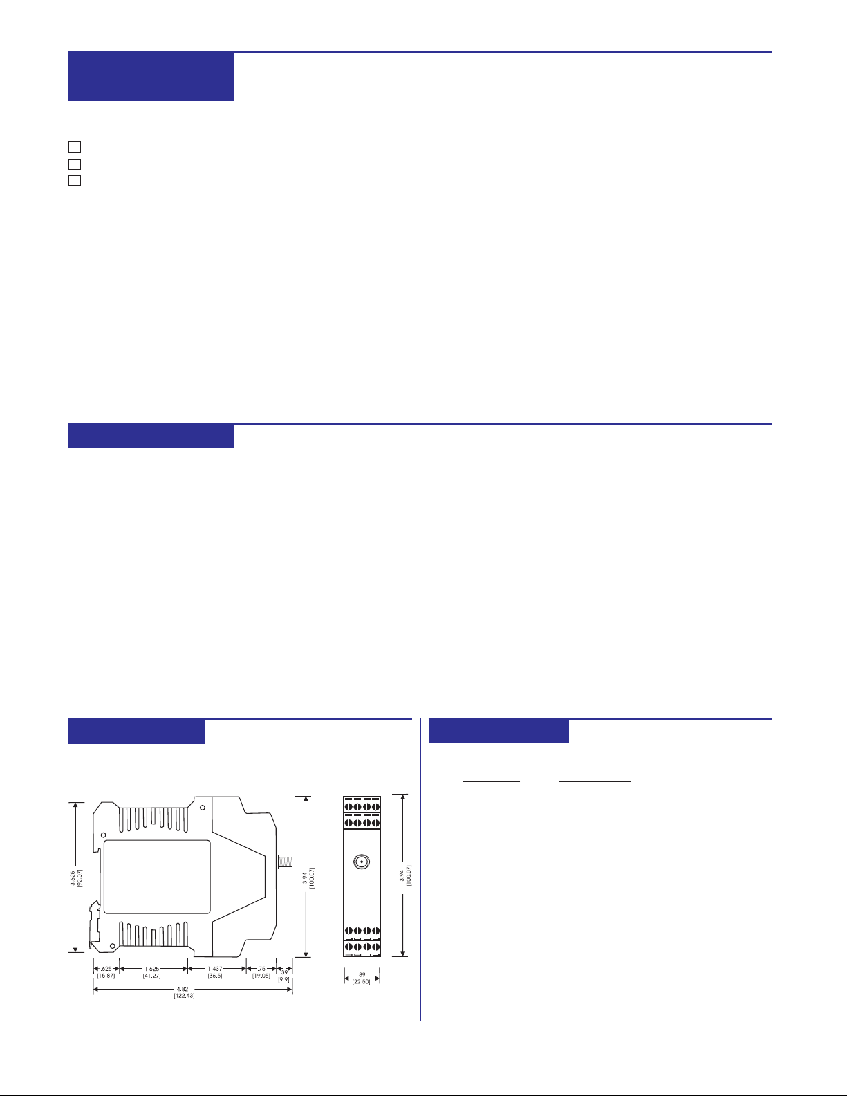
DIMENSIONS
Inches [mm]
28
CONNECTIONS
TERMINAL
1
2
3
4
5
6
7
8
9
10
11
12
13
14
15
16
CONNECTION
RS485 Terminal A
RS485 Terminal B
RS485 Common
RS485 Shield
RS485 Terminal A
RS485 Terminal B
RS485 Terminal A
RS485 Terminal B
RS232 RX
RS232 TX
RS232 Ground
RS232 Ground
No Connection
No Connection
AC L1 Power
AC L2 Power
(Termination Resistor
}
Connection)
 Loading...