

Wilkerson Instrument DR4300 Operating Manual
DR4300
DC INPUT
FIXED RANGE
ISOLATED TRANSMITTER
DIN RAIL MOUNT
DESCRIPTION
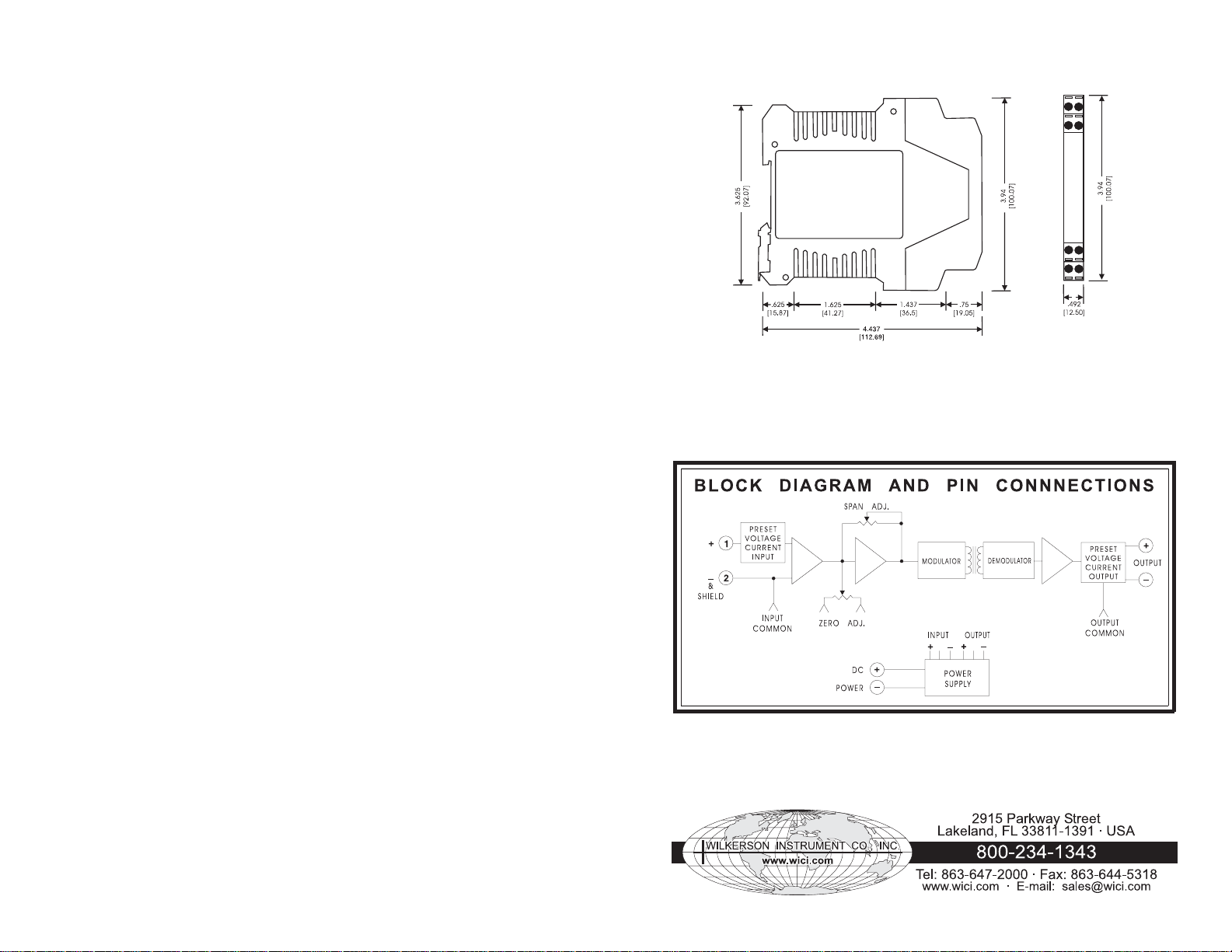
The DR4300 provides an isolated
DC voltage or current output
proportional to a DC voltage or
current input. The input and output
are ranged at the factory, but Zero
and Span controls provide ±15%
adjustability.
The DR4300 provides 3 way
isolation between input, output, and
power source.
The isolation makes the product
useful for measuring input signals
with high common mode voltages
and for breaking ground
connections to eliminate ground
loops. Its wide choice of inputs and
outputs allow signal conversion and
scaling as well.
The screw terminal blocks plug into
the case, which allows easy wiring
and removal of products.
All of the DR Series of products
provide transient protection to help
eliminate damage from lightning and
from other transients created on the
power and signal leads.
INSTALLATION
The DR Series of products mount
on standard 35 mm DIN rails. Install
by hooking the top of the case’s latch
onto the top of the DIN rail. Then
push down on the case, letting it
pivot on the DIN rail. The bottom
slide of the mount will snap behind
the rail and secure the product.
To remove, insert a screwdriver into
the hole on the metal latch on the
bottom of the case, and pull the latch
down until it allows the front of the
case to be lifted up.
WARRANTY
The DR Series of products carry a
limited 3 year warranty. In the event
of a failure due to defective material
or workmanship, the unit will be
repaired or replaced at no charge.
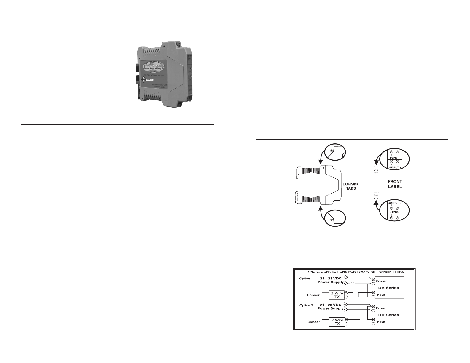
CALIBRATION
The DR4300 is factory calibrated to the input and output noted on the
case side label. Terminal connections are shown on the front label.
To make field adjustments to the product:
1. Remove the circuit board from the case by squeezing the
2 locking tabs (see diagram below) and pulling the case
front, with the circuit board, out of the case.
2. Connect a calibrator to the input terminals.
3. Connect an accurate voltmeter or current meter to the output
terminals.
4. Apply power to the unit.
5. Set the input for its zero scale and adjust the Zero control for
zero scale output.
6. Set the input for its full scale and adjust the Span control for
full scale output.
7. Repeat once or twice until no further adjustment is required.
TWO-WIRE TRANSMITTER WIRING
In installations where isolation between the power supply and the input
terminals is not required, the DR Series power supply can also be used to
power a Two-Wire Transmitter (see drawing below). If isolation is required,
a separate power supply must be used to power the Two-Wire Transmitter.
1 2
SPECIFICATIONS
INPUT RANGE
Voltage
Select any range between
± 50 mV to ± 256 V
(Minimum span 50 mV)
(Maximum span 256 V)
Current
Select any range between
± 1 mA to ± 250 mA,
internal shunt
(Minimum span 1 mA)
(Maximum span 250 mA)
INPUT IMPEDANCE
Voltage
400 kilohms
Current
Current Input Input Shunt
Value
1 mA
10 mA
20 mA
4/20 mA
100 mA
250 mA
BANDWIDTH
-3db at 3 Hz
ISOLATION,
OUTPUT/INPUT/POWER
>500 megohms
1500 VAC rms
1000 OHM
100 OHM
50 OHM
61.9 OHM
10 OHM
3.3 OHM
CASE DIMENSIONS INCHES [mm]
OUTPUT RANGE
Voltage
Select any range from
-10 V to +10 V, 5 mA max
load (min span 1 V)
Current
Select any range from
0 to 20 mA
(min span 1 mA)
Compliance > 20 V
(Drive 1000 ohm at 20 mA)
OUTPUT RIPPLE (peak to peak)
<0.1% of span
ACCURACY
±0.1% of span
LINEARITY
±0.05% of span
COMMON MODE REJECTION
100 dB, DC to 60 Hz
OPERATING TEMPERATURE
14°F to 158°F/-10°C to 70°C
TEMPERATURE STABILITY
±(0.01% of span)/°C max
POWER
21 to 28 VDC, 50 mA max
Specifications Are Subject To Change Without Notice. © 2007 Wilkerson Instrument Co., Inc. DWG#W103758 3/07
3
4
 Loading...