

Wilkerson Instrument DR1920 Data sheet
DR1920
Duplex Lift Station Back-Up Pump Controller
FEATURES
• Runs one or two
pumps for fixed time
interval set by user
• Isolated digital input
in addition to a NO
or NC switch contact
input
• 10 Amp NO relay contact for
each pump
• Open collector control
output for each pump
• DIN Rail Case
• 5 Year Warranty
• UL/cUL Recognize
d
DESCRIPTION
The DR1920 Back-Up Pump Control is a compact
DIN rail mounted unit used to monitor a backup level
alarm in a tank or wet well and start up to two pumps
when a high alarm switch closes. The unit is used as
a backup to normal tank / well level controls and is
wired to the High-High Alarm switch to prevent
overflows in situations where the primary level
control system fails.
When the level switch in the tank or well closes, the
DR1920 closes a relay that starts Pump 1 and starts
an internal Timer 1. When Timer 1 reaches its set
time, and the level alarm switch is still closed, Pump
2 is started. Pump 1 and Pump 2 will run until the
level alarm switch opens. When the level switch
contact opens, Timer 2 is started and both pumps
continue to run until Timer 2 reaches its set time.
SPECIFICATIONS
POWER
85/250 VAC ±10% 50/60 Hz,
2 VA
ALARM INPUTS
NO or NC switch contact
Isolated switch or Open
collector transistor
Internal jumper to set “open” or
“close” to alarm
PUMP CONTROL
Two NO 10A (Form A) relay
contacts
If the alarm switch opens during the Timer 1 interval,
Timer 2 is started when the switch opens. Pump 2 is
not started and Pump 1 will run until Timer 2 reaches
its set time.
The DR1920 also has provisions to alarm on a switch
opening.
ALARM SWITCH MONITOR
The DR1920 monitors the open or closed status of a
switch contact that is already wired into a control
system. This switch may have any of several
voltages that are used to control the pump system.
In addition, if the primary control system fails, the
normal voltages may not be present.
The DR1920 is wired across the alarm switch contacts
and uses a unique circuit that measures the impedance
present between the switch contacts. When the
DR1920 senses a low impedance, it begins its control
OUTPUT
Closes for Pump 1 and
Pump 2 run
Two optically isolated NPN
transistor Sink or source 30 mA
TIMERS
Timer 1 - Pump 2 delay
Adjustable 2 to 126 seconds
(2.1 minutes) in 2 second
increments
Timer 2 - Pump Run Time
Adjustable 5 to 1,275 seconds
(21.25 minutes) in 5 second
increments
Timers are set with binary
coded DIP switches inside the
enclosure
function, regardless of any absence or presence of
voltage across the switch contacts. This feature
allows the DR1920 to be wired in parallel across the
switch contacts without regard to the existing control
system, permitting simple installation in existing
systems. For situations where the existing wiring
prevents this circuit from being used, an isolated
contact must be provided. A second input, which
requires an isolated contact or open collector transistor
is also provided.
A Reset input is provided to stop the pumps and
reset the timers. It requires a contact closure or
open collector transistor.
Since the Back Up Pump Control is used only when
there is a problem with the primary control, the digital
alarm inputs, as well as the reset inputs, are provided
to allow the periodic exercising of the system to
verify functionality.
RESET INPUT
Stop pumps and reset timers
Requires contact closure or
open collector transistor
INDICATORS
LED Indicators for -
Pump 1,
Green OFF, Red RUN
Pump 2
Green OFF, Red RUN
ENCLOSURE
DIN Rail Mount
3.9H X 4.48D X 0.87W
Plug-in screw terminals
157
DR1920
ORDERING
INFORMATION
Wilkerson Instrument Co., Inc. Copy and Fax to Place Order.
ACCESSORIES
DR1 DIN-Rail, 35 mm Symmetrical, 39 inches (1meter) Qty ____
DIMENSIONS
Inches [mm]
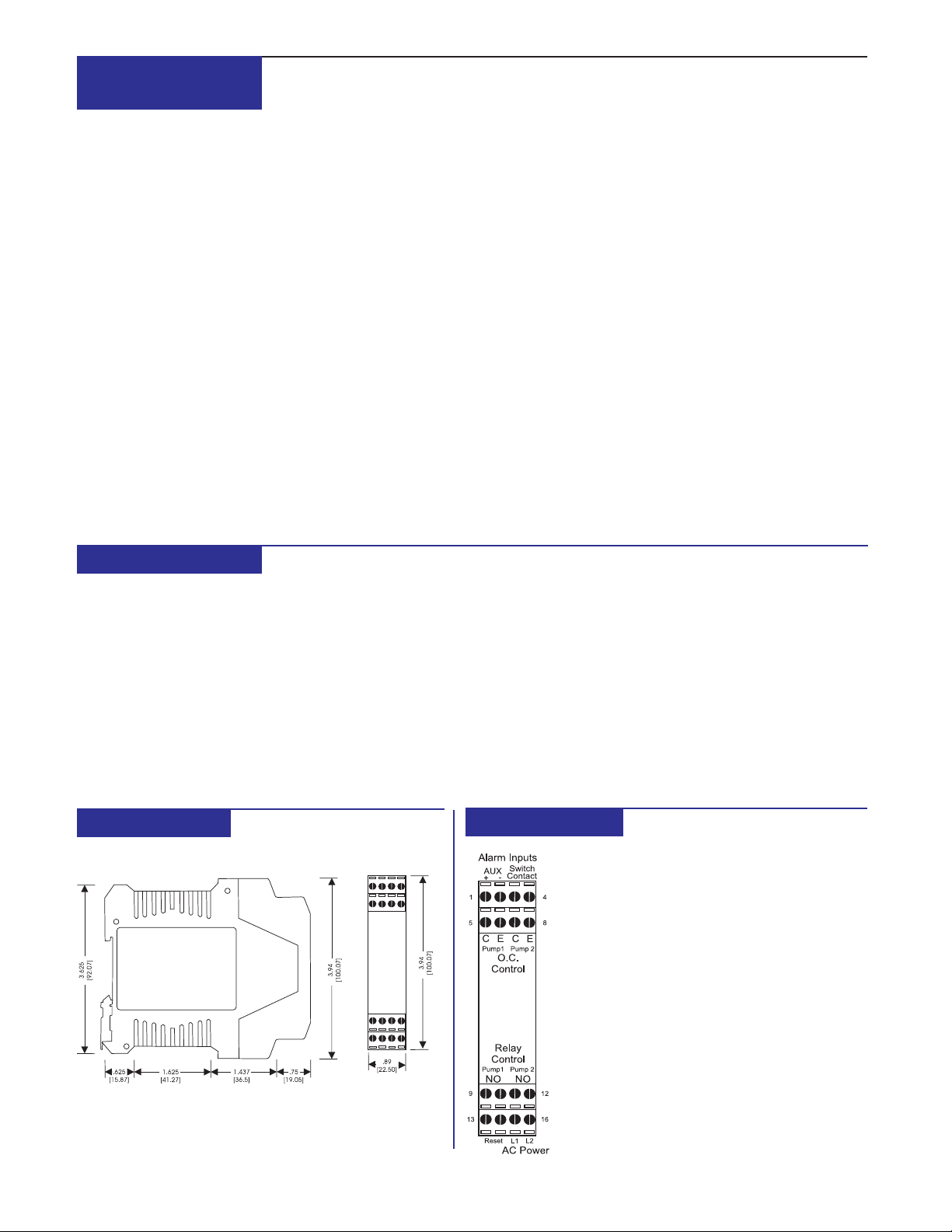
CONNECTIONS
TERMINAL CONNECTION
1 + AUX Alarm Input - Isolated Input
2 - AUX Alarm Input - Isolated Input
3 Alarm Switch Contact Input
4 Alarm Switch Contact Input
5 Pump 1 O.C. Control - Collector
6 Pump 1 O.C. Control - Emitter
7 Pump 2 O.C. Control - Collector
8 Pump 2 O.C. Control - Emitter
9 Pump 1 Relay - SPST - Close on Alarm
10 Pump 1 Relay - SPST - Close on Alarm
11 Pump 2 Relay - SPST - Close on Alarm
12 Pump 2 Relay - SPST - Close on Alarm
13 Reset Input +
14 Reset Input 15 AC Power - L1
16 AC Power - L2
158
 Loading...