

Wilkerson Instrument DM7010 Operating Manual
DM7010
FREQUENCY INPUT
FIELD RANGEABLE
ISOLATED TRANSMITTER
The DM7010 provides an isolated output
voltage or current proportional to the
frequency of the input AC voltage. The wide
input voltage range allows the module to be
used with low level magnetic pick-ups, for
flow or speed applications, for digital signals,
or for direct power line monitoring.
A selectable pull-up resistor allows input
drive from switch closure or open collector
transistor. Also, CMOS or TTL inputs are
accepted.
The output is fully isolated from input, line
power, and ground. The unit is useful for
eliminating ground loops and for isolating
from common mode voltages. The DM7010
utilizes a feedback voltage controlled
oscillator to develop a digital signal with a
duty cycle proportional to the input signal
amplitude. This signal is coupled through an
isolating pulse transformer to the output
circuitry, where the duty cycle data is
converted to a proportional output signal
level.
The module includes filtering and conditioning
to reduce susceptibility to transients and
noisy environments.
Input and output ranges are fully usersettable. With handy gold plated jumper
connections, the user selects and sets input frequency span, filter capacitor, voltage/
current output, output range, and normal/
reverse acting output. Input span and zero
adjustments provide full range adjustability.
All adjustments, settings, and input and
output connections are easily accessed
from under a pull off/push on cover panel. A
write-on label is supplied on the front panel
for the user’s convenience.
The DIN Rail package snaps onto the rail and
is easily removed from the front side by using
a screwdriver to release the spring loaded
snap.
OPTIONS
(User specified)
AC Power 24, 115 or 230 VAC
DC Power 12 or 24 VDC
U All circuit boards conformal coated for
protection against moisture.
INSTALLATION
DM7010 mounts on standard DIN Rail. Install
it by hooking the top of the module’s latch
onto the top of the rail, then use a downward
rotating motion to snap the module onto the
rail. To remove the module, insert a
screwdriver into the slot on the spring loaded
snap which is located on the lower backside
of the unit. Apply a downward pressure on
the release and rotate the module up and off
of the rail.
1. Remove the front panel by spanning the
top and bottom edges between the thumb
and index finger. Use a rocking motion to
pull the front panel away from the module.
2. Input, Output and Power connections are
shown on the terminal block labels.
CAUTION: BEFORE PROCEEDING,
REMOVE ALL POWER TO THE WIRES
AND MODULE TO AVOID THE DANGER
OF SHOCK AND/OR DAMAGE TO THE
UNIT.
To access input and output terminals, the
connecting wires are inserted into the top
of the top terminal block, and into the
bottom of the bottom terminal block. The
terminal blocks unplug. Wiring can be
completed before the product is installed.
Recommended wire sizes are 22-14 AWG
Cu, with a strip length of 0.25 inches.
3. Replace the front panel by inserting the pins
into the slotted holes located on the bezel
and pushing it into position.
4. The front panel label provides space for the
user to make application notes.
CALIBRATION
The DM7010 is factory calibrated to the input
and output noted on the side label.
The DM7010 allows the user to calibrate the
module to operate as required for a specific
application.
Field adjustments can be made by using the
following recommended procedure.
CAUTION: BE SURE ALL RANGE
SELECT JUMPERS ARE SET TO THEIR
PROPER POSITIONS BEFORE
APPLYING INPUT OR POWER.
1. Remove the front panel and disconnect the
power.
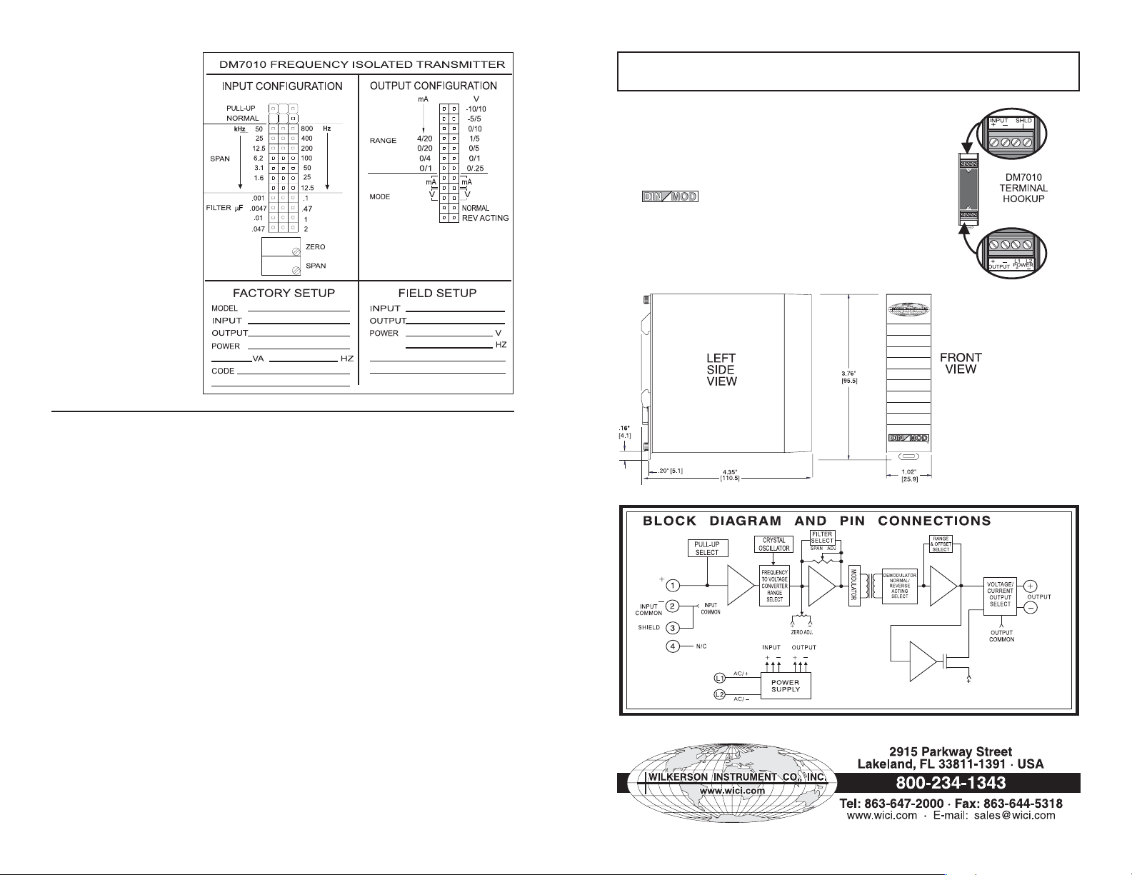
2. Using the label on the side of the module
(Figure 1) as a guide, position the jumper
blocks for the desired operation of the
following functions:
span -
Choose the frequency span which
includes the maximum inputfrequency.
pull-up/normal -
ohm to +5 Volts load to the input terminal.
filter capacitor -
chart to obtain the desired filter and response
time.
output range -
range to obtain the desired output.
output mode -
this selection must be made in conjunction
with the output range selection. There are
two jumper positions for this selection, both
must be selected.
normal or reverse acting output -
for the output to increase as the input
increases, select reverse for the output to
decrease with increasing input.
3. Connect calibrated frequency source to the
input; and meters to the input and output
terminals. Apply power to the module.
4. Set the input frequency to represent the zero
level, the lowest value of the input span.
5. Observe the output meter. Use the ZERO
adjustment to raise or lower the output to the
desired zero level.
Choose pull-up to add a 4700
Use the filter capacitor selection
Select the voltage or current
Select either voltage or current,
Select normal
6. Set the input frequency to represent the
upper limit of the SPAN, the highest value
of the input span.
7. Observe the output monitor. Use the SPAN
adjustment to raise or lower the output to
the desired maximum level.
8. Repeat steps 4 to 7 to fine tune the output.
Usually 3 repetitions will give the desired
results.
9. Remove power, disconnect test equipment
and install the module for operation.
Replace the front panel.
Example for Frequency and Filter
Selection:
Input Frequency: 100 Hz to 1000 Hz
Maximum Ripple: .1%
Output: +5/-5 Volts
Actual Span: 900 Hz
(must include maximum input frequency)
Select Span Jumper for 1600 Hz
Select Filter Capacitor Jumper for 0.1µF
(from the Chart)
Select Output Mode Jumpers for Volts
(two positions)
Select Output Mode Jumper for
REV ACTING
Select Output Range Jumper for -5/+5
Set input frequency to 100 Hz
Adjust Zero for +5 Volt output
Set Input frequency to 1000 Hz
Adjust Span for -5 Volt output
Repeat adjustments for accurate
calibration
FILTER CAPACITOR SELECTION CHART
FREQUENCY
SPAN
SETTING
HERTZ
12500 0.01 0.5 0.0047 0.24
25000 0.01 0.5 0.0047 0.24
50000 0.0047 0.24 0.001 0.05
MINIMUM CAPACITOR*
SETTING FOR LESS THAN
0.1% RIPPLE PEAK-PEAK
.
CAPACITOR
RESPONSE
(uF)
TO 99%
12 2.2 110 1.0 50
25 2.2 110 1.0 50
50 1.0 50 0.47 24
100 1.0 50 0.47 24
200 0.47 24 0.47 24
400 0.47 24 1.0 5
800 0.47 24 0.047 2.4
1600 0.1 5 0.047 2. 4
3200 0.047 2.4 0.047 2. 4
6400 0.047 2.4 0.01 0.5
(*SEC) **
MINIMUM CAPACITOR*
SETTING FOR LESS THAN
0.5% RIPPLE PEAK-PEAK
CAPACITOR
RESPONSE
(uF)
TO 99%
(*SEC) **
1 2
* The minimum capacitor
value is based on full span
where the minimum frequency is 0.1% of the frequency setting. When the
minimum frequency to be
measured is greater than
0.1% of the frequency setting, the capacitor value may
be decreased to improve
the response time.
** The minimum frequency
which will meet the ripple
specifications is 0.5 Hertz.
Figure 1
SPECIFICATIONS
INPUT
Frequency Range
10 Hz to 50 kHz
Impedance
100,000 ohms
Coupling AC
Voltage range
50 mV to 700 V p-
p
Span Select
(User settable)
12, 25, 50, 100,
200, 400, 800,
1600, 3200, 6400,
12500, 25000 and
50000 Hz
Span adjustment
+5%, -55% of
selected span
Zero adjustment
±30% of selected
span
Offsets
(User settable)
None
Pull-Up Resistor
4.7 kilohm (+5 VDC)
OUTPUT
Modes
Normal/
Reverse Acting
Range
(User settable)
0/.25, 0/1, 0/5,
0/10, -5/5,
& -10/10 VDC
0/1, 0/4, 0/20,
& 4/20 mAdc
Accuracy
0.1% of span
Step response time
see FILTER
CAPACITOR
SELECTION CHART
Ripple
(peak-to- peak)
see FILTER
CAPACITOR
SELECTION CHART
Input to Output
Linearity
±0.01% of span
COMMON MODE
REJECTION
120 dB DC
to 60 Hz
ISOLATION,
OUTPUT/INPUT
>500 megohms
BREAKDOWN,
OUTPUT TO INPUT
>1000 volts
RMS sinewave
BREAKDOWN,
POWER CIRCUITRY
>1500 volts
RMS sinewave
OPERATING
TEMPERATURE
-13° to 140°F
(-25° to 60°C)
TEMPERATURE
STABILITY
±(0.01% of span)/°C
POWER
Wattage
2.5 W max
AC Options
115 VAC
±10%,
50/60 Hz
230 VAC
±10%,
50/60 Hz
24 VAC
±10%,
50/60 Hz
DC Options
12 VDC nominal
(10 to 15 VDC)
24 VDC nominal
(21 to 28 VDC)
CAUTION: THE DIN/RAIL SHOULD BE EARTH GROUNDED (GREEN WIRE) TO
ENSURE SAFEST OPERATION AND TO PROVIDE OPTIMUM PERFORMANCE.
MOUNTING
The DIN Rail package is installed by snapping it onto
the rail and it is removed from the front side by using
a screwdriver to release the spring loaded snap
(located on the lower backside of the unit).
WARRANTY
The Series of products carry a limited
permanent warranty. In the event of a failure due to
defective material or workmanship, the unit will be
repaired or replaced at no charge. Relays are not
covered by the warranty.
CASE DIMENSIONS INCHES [mm]
Specifications Are Subject To Change Without Notice. © 2007 Wilkerson Instrument Co., Inc. DWG#W102762D 3/07
3 4
 Loading...