

Page 1
FIND OUT MORE
FIND OUT MORE
ON THE WEB.
ON THE WEB.
WILBURCURTIS.COM
WILBURCURTIS.COM
WILBUR CURTIS COMPANY, INC.
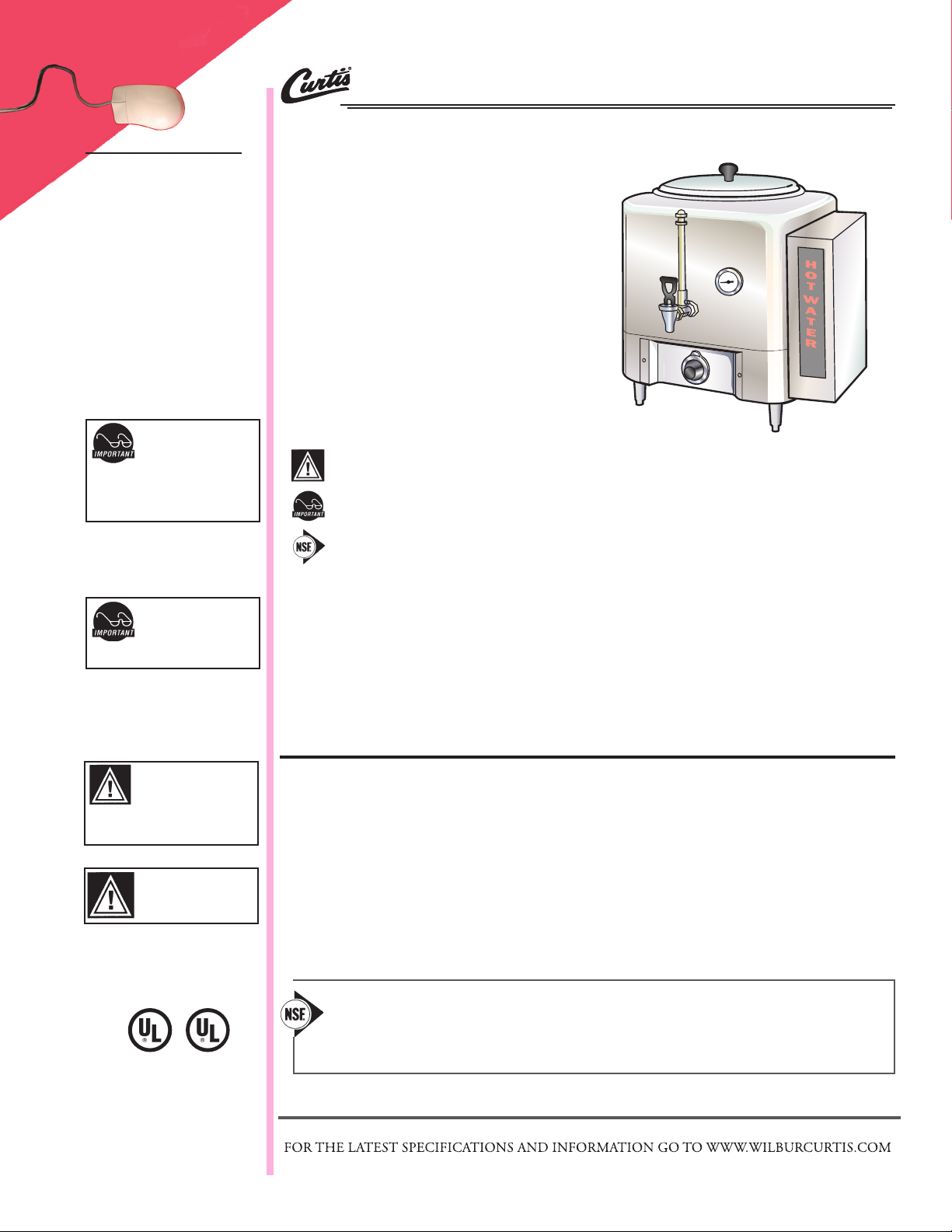
Water Boiler, 14 Gallon – Instructions
MODELS INCLUDED
• WB-14-12
CAUTION: Please use
this setup procedure
before attempting to use
this brewer. Failure to follow the
instructions can result in injury or the
voiding of the warranty.
CAUTION: DO NOT
connect this unit to hot
water. The inlet valve is
not rated for hot water.
Important Safeguards/Conventions
This appliance is designed for commercial use. Any
servicing other than cleaning and maintenance should be
performed by an authorized Wilbur Curtis service center.
• To reduce the risk of fire or electric shock, do NOT
open side or bottom panel. No user serviceable parts
inside.
Repair should be performed only by authorized
service personnel.
• Keep hands and other items away from hot parts of
unit during operation.
• Never clean with scouring powders, bleach or harsh
implements.
Conventions
WARNINGS – To help avoid personal injury
Important Notes/Cautions – from the factory
Sanitation Requirements
The Curtis Water Boiler is Factory Pre-Set and Ready to Go… Right from the Carton.
Factory Settings:
• Water Temperature = 200°F • Volume = 14 Gallons
System Requirements
• Water Source: 20 – 100PSI (Min Flow Rate of 1 GPM) • Electrical: See attached schematic for standard
model or visit www.wilburcurtis.com for your model.
Equipment to be installed to comply with applicable federal, state, or local plumbing/electrical codes having jurisdiction.
WARNING: DO NOT
place this water boiler
closer than six [6] inches
from wall. Unit must have
adequate cross-ventilation.
WARNING HOT LIQUID,
Scalding may occur.
Avoid splashing.
C
ISO 9001 REGISTERED
WILBUR CURTIS COMPANY
Montebello, CA 90640
SETUP STEPS
1. Place unit at counter height. on a firm, level base, in such a way that it can be connected to water and power supply.
2. Install the supplied water faucet on the faucet shank in front of the unit.
3. Connect water line to inlet fitting on valve. It is recommended that some type of water mineral reducing filter be used
in the water line before entering the unit. Water pressure entering boiler is must be stable and provide minimum of
1 gallon per minute. Use water regulator for constant pressure. Required water pressures, 20 to 100 psi. Turn on
water valve.
5. Hook-up power to the unit (refer to schematic for power requirements).
6. Turn on the circuit running power to unit. The water inlet valve will open, filling the unit. When the boiler has filled,
turn on boiler at the thermostat, twisting the knob clockwise.
7. Heating tank will require 50 to 60 minutes to attain operating temperature. Thermostat indicator will light at this time.
The National Sanitation Foundation requires the following water connection:
1. A quick disconnect or additional coiled tubing (at least 2x the depth of the unit) so that the machine can be
moved for cleaning underneath.
2. In some areas an approved backflow prevention device may be required between the boiler and the water
supply.
Page 2
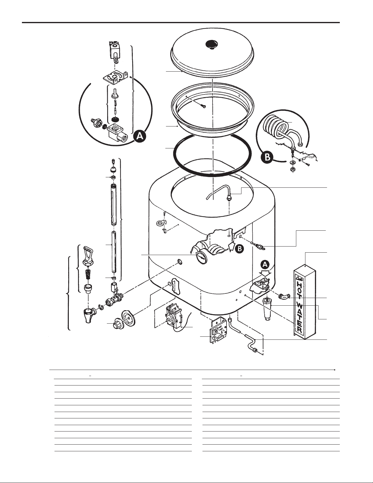
Illustrated Parts List
1
19
20
17
16
13
14
15
12
22
2
21
3
4
5
6
7
8
9
ITEM
1
2
3
4
5
6
7
8
9
10
11
WC-5602
WC-6118-01
WC-4303
WC-5335
WC-5502
WC-5510
WC-2401
WC-3500
WC-5334
WC-37137
WC- 608
18
DESCRIPTIONPART Nº
LID, 6 GAL WITH KNOB
COLLAR, TOP
“O” RING, LINERS RU
TUBING, 8” WATER INLET
PROBE, WATER LEVEL
COVER, PROBE WA WB14
ELBOW, 3/8 NPT X 1/4 FLRE PLTD
LEG, 4” ADJUSTABLE 3/8-16 THRD
TUBING, 15-1/2” WATER INLET
KIT, THERMOSTAT WB-14
LEVEL CONTROL, WATER 120V
10
11
ITEM
12
13
14
15
16
17
18
19
20
21
22
WC-2100
WC-2005
WC-2024
WC-2006
WC-3705
WC-1800HW
WC-3217
WC- 801
WC-3700
WC- 922-04
WC- 511
DESCRIPTIONPART Nº
GAUGE GLASS ASSY, 7”
WASHER, 1/8” SHIELD CAP
GLASS, GAUGE 7”
WASHER, 3/16” SHIELD BASE
REPAIR KIT, S FAUCET
FAUCET, S’ S
KNOB, ELECTRIC THERMOSTAT
VALVE, WATER INLET
REPAIR KIT, INLET VALVE
HEATING ELEMENT, 3500W, 220V
THERMOMETER, DIAL RU’S
ERIES H/W
2
Page 3

6 3
1 2
L
PROBE
ORANGE
RED #10
THERMOSTAT
WHITE
WHITE
BLUE
BLACK #10
BLUE #10
T1
T2
T3
T4
WATER
LEVEL
CONTROL
BOARD
Single Phase 3 Wire
208 VOLT, 6300 WATT, 30 AMP
220 VOLT, 7000 WATT, 32 AMP
240 VOLT, 8400 WATT, 35 AMP
L1
N
L2
2 - 3.5 KW HEATING
ELEMENTS
Water Boiler WB-14 -12
220 VOLTS, 7000 WATTS, 32 AMPS, 1Ø
L
PROBE
ORANGE
RED #10
THERMOSTAT
WHITE
WHITE
BLUE
BLACK #18
N
2 - 3.5 KW HEATING
ELEMENTS
BLUE #10
T1
T2
T3
T4
WATER
LEVEL
CONTROL
BOARD
L1
6 3
1 2
L2
POWER
BLOCK
1
2
3
POWER
BLOCK
1
2
3
4/13/07
INLET VALVE
2 GPM 10W/120V
INLET VALVE
2 GPM 10W/120V
4/13/07
3
Page 4

Electric Thermostat
Adjustment
ELECTRIC THERMOSTAT ADJUSTMENT
On electric water boilers, thermostats are set at the factory to cut off at 200ºF. We do not recommend changing this. If necessary, adjustment is as follows:
1. Rotate the thermostat knob to the right to the BOIL position. Pull off the knob.
2. Locate the tiny adjustment screw, inside the stem (see figure 1). Using a small screwdriver, adjust the
temperature up or down:
a. By turning the screw ¼ turn to the left will increase the temperature about 20°F.
b. Turning ¼ to the right will decrease the temperature by 20°F.
c. To set the thermostat precisely at 200°F, insert a thermometer probe into the water jacket through
the steam hole (just under the sprayhead). Turn the screw ½ turn to the left.
d. When the thermometer reaches 200°F, slowly turn the adjustment screw to the right until the pilot
light turns off.
Product Warranty Information
The Wilbur Curtis Company certifies that its products are free from defects in material and workmanship under normal use. The following limited
warranties and conditions apply:
3 Years, Parts and Labor, from Original Date of Purchase on digital control boards.
2 Years, Parts, from Original Date of Purchase on all other electrical components, fittings and tubing.
1 Year, Labor, from Original Date of Purchase on all electrical components, fittings and tubing.
Additionally, the Wilbur Curtis Company warrants its Grinding Burrs for Forty (40) months from date of purchase or 40,000 pounds of coffee, whichever
comes first. Stainless Steel components are warranted for two (2) years from date of purchase against leaking or pitting and replacement parts are
warranted for ninety (90) days from date of purchase or for the remainder of the limited warranty period of the equipment in which the component is
installed.
All in-warranty service calls must have prior authorization. For Authorization, call the Technical Support Department at 1-800-995-0417. Effective
date of this policy is April 1, 2003.
Additional conditions may apply. Go to
www.wilburcurtis.com to view the full product warranty information.
CONDITIONS & EXCEPTIONS
The warranty covers original equipment at time of purchase only. The Wilbur Curtis Company, Inc., assumes no responsibility for substitute replacement parts installed on Curtis equipment that have not been purchased from the
Wilbur Curtis Company, Inc. The Wilbur Curtis Company will not accept any responsibility if the following conditions are not met. The warranty does
not cover and is void under the following circumstances:
1) Improper operation of equipment:
2) Improper installation of equipment: This equipment must be installed by a professional technician and must comply with all local electrical,
mechanical and plumbing codes.
3) Improper voltage:
4) Improper water supply: This includes, but is not limited to, excessive or low water pressure, and inadequate or fluctuating water flow rate.
5) Adjustments and cleaning: The resetting of safety thermostats and circuit breakers, programming and temperature adjustments are the respon
sibility of the equipment owner. The owner is responsible for proper cleaning and regular maintenance of this equipment.
6) Damaged in transit: Equipment damaged in transit is the responsibility of the freight company and a claim should be made with the carrier.
7) Abuse or neglect (including failure to periodically clean or remove lime accumulations): Manufacturer is not responsible for variation in equipment
operation due to excessive lime or local water conditions. The equipment must be maintained according to the manufacturer’s recommenda
tions.
8) Replacement of items subject to normal use and wear: This shall include, but is not limited to, light bulbs, shear disks, “0” rings, gaskets, silicone
tube, canister assemblies, whipper chambers and plates, mixing bowls, agitation assemblies and whipper propellers.
9) Repairs and/or Replacements are subject to our decision that the workmanship or parts were faulty and the defects showed up under normal
use. All labor shall be performed during regular working hours. Overtime charges are the responsibility of the owner. Charges incurred by delays, waiting time, or operating restrictions that hinder the service technician’s ability to perform service is the responsibility of the owner of the
equipment. This includes institutional and correctional facilities. The Wilbur Curtis Company will allow up to 100 miles, round trip, per in-warranty
service call.
RETURN MERCHANDISE AUTHORIZATION: All claims under this warranty must be submitted to the Wilbur Curtis Company Technical Support
Department prior to performing any repair work or return of this equipment to the factory. All returned equipment must be repackaged properly in
the original carton. No units will be accepted if they are damaged in transit due to improper packaging. NO UNITS OR PARTS WILL BE ACCEPTED WITHOUT A RETURN MERCHANDISE AUTHORIZATION (RMA). RMA NUMBER MUST BE MARKED ON THE CARTON OR SHIPPING
LABEL. All in-warranty service calls must be performed by an authorized service agent. Call the Wilbur Curtis Technical Support Department to
find an agent near you.
Equipment must be installed at the voltage stated on the serial plate supplied with this equipment.
The equipment must be used for its designed and intended purpose and function.
-
-
WILBUR CURTIS CO., INC.
6913 Acco St., Montebello, CA 90640-5403 USA
Phone: 800/421-6150 Fax: 323-837-2410
Technical Service Phone: 800/995-0417 (M-F 5:30A - 4:00P PST) E-Mail: techservice@wilburcurtis.com
Web Site: www.wilburcurtis.com
4
FOR THE LATEST SPECIFICATION INFORMATION GO TO WWW.WILBURCURTIS.COM
Printed in U.S.A. 4/07 F-1981 Rev A
 Loading...