

Page 1
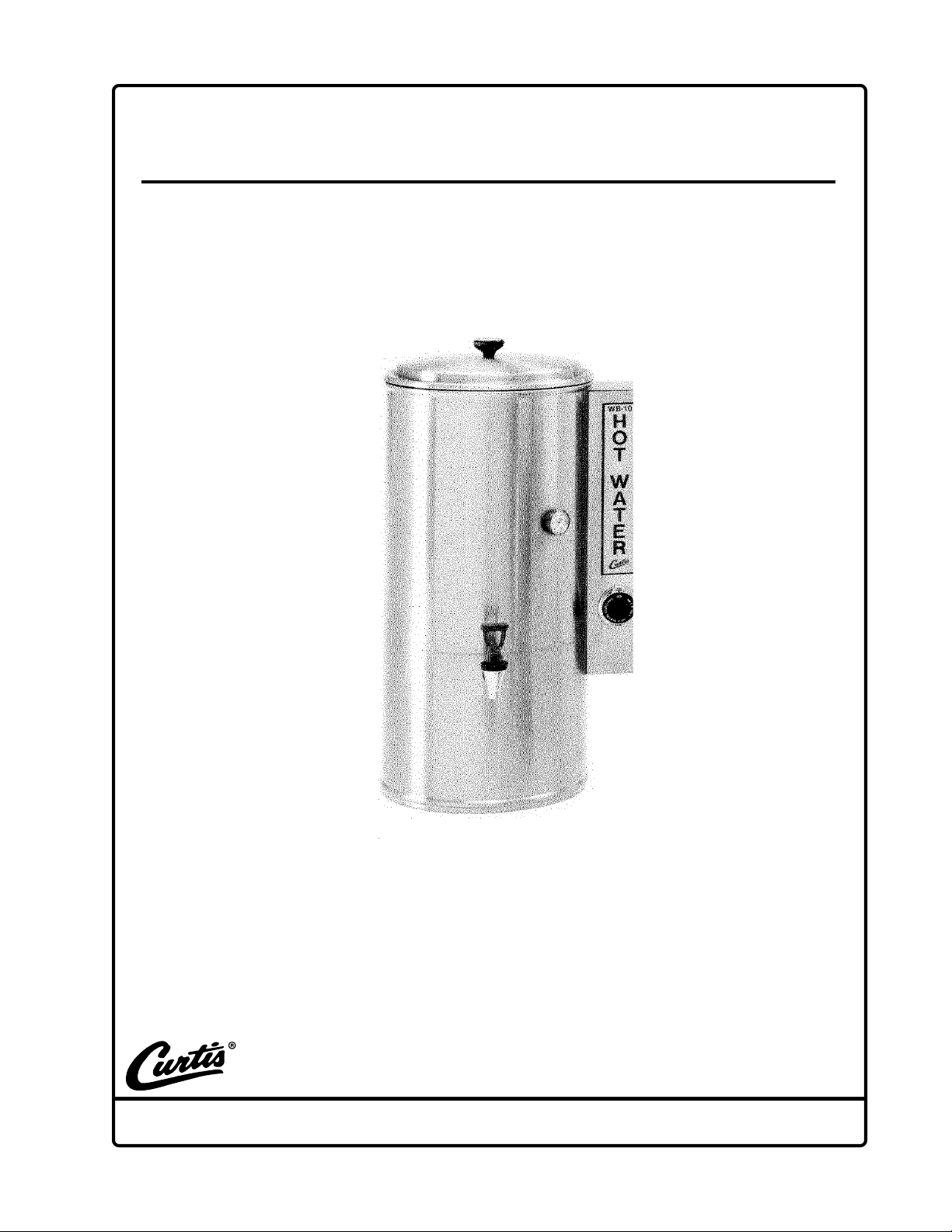
WATER BOILER WB-10 -12
Revised 7/04
6913 West Acco Street, Montebello, California 90640
Tel: 800/421-6150 Technical Support Tel: 800/995-0417 Fax: 323/837-2401
Page 2

WATER BOILER - WB-10 -12
INSTALLATION INSTRUCTIONS
1. Unpack equipment carefully, inspect for any freight damage. Be sure to promptly
put a claim into the freight company if any damage is found.
2. Connect faucet securely to the faucet adapter.
Electrical and plumbing hook-ups should be made by authorized installers only.
INSTALLATION MUST COMPLY WITH ALL NATIONAL AND LOCAL ELECTRICAL AND
PLUMBING CODES.
3. This water boiler can operate on 120, 208 or 220 volt power supply. To ground equipment, connect the ground wire to the green screw on inside bottom of wrap.
4. This boiler comes wired for 208 or 220 volt, single phase, 3 wire plus ground, see wiring
diagram.
5. To connect the water boiler for 120 volt operation:
A. The facility will have two wires, one WHITE (neutral) and the other BLACK. Plus
GREEN for ground.
B. Splice the BLACK wire from power source, to both the heavy RED (#10 AWG) and
thin BLACK (#18 AWG) wires from the WB-10.
C. Take the WHITE wire from the facility power source and splice it to the BLUE wire
(#10 AWG) and WHITE wire (#18 AWG) from the machine (see wiring diagram).
6. Water Hook-Up: Use a 1/4" copper line with a female flare fitting. Water inlet fitting is
located on the back of the WB-10.
CAUTION Before turning thermostat dial to ON position, fill equipment with water up
to the probe tip. This will prevent heating elements from burning out.
1
Page 3
TROUBLE SHOOTING
PROBLEM: WATER WILL NOT REFILL
POSSIBLE CAUSE
1. Water line closed
or clogged filter
Check the water system at your facility to make sure the line is
open. Replace the water filter.
SOLUTION
2. Valve coil burned
out
3. Grounded probe
4. Defective water
level control
board
PROBLEM: WATER OVERFLOWING.
POSSIBLE CAUSE
1. Defective water
inlet valve
Turn machine off. Disconnect wires from water inlet coil terminals
and connect a power cord to the terminals. Plug cord into a 120V
outlet and verify if water flows when plugged in and stops when
power is disconnected. If valve fails this test, replace valve.
When the water level gets below the probe tip, water should
automatically refill the unit. If not, pull wire off the probe terminal. Water should now start flowing into the water boiler.
Disconnect wire from probe terminal. With a voltmeter, check
voltage at the water inlet coil terminals. This should read 110-120
volts. If no voltage is present, check liquid level control (L.L.C.)
board. Make sure the L.L.C. board is supplied by 120V across
terminals T2 & T3. The L.L.C. board is grounded to the body of
the machine by contacting the board to the mounting bracket.
Make sure board is grounded here. Check for loose connections
at terminals. Replace board.
Turn power off and observe water level. If water continues to flow
into the heating tank, clean or replace leaky valve.
SOLUTION
2. Probe limed up
3. Non-grounded or
loose terminal
connections at
liquid level control board
PROBLEM: WATER DOES NOT REACH PROPER TEMPERATURE
POSSIBLE CAUSE
1. Thermostat
turned OFF (or
set too low)
Disconnect wire from probe terminal. Touch the body of the heating tank with the terminal at the end of this wire. If water stops,
try cleaning the probe. Probe may have to be replaced.
Liquid level control board must be securely grounded through the
back of the board and the mounting bracket. Check for loose
connections at the terminals. Check for voltage across the inlet
valve terminals. If there is 110 to 120 volts present at the inlet
valve terminals when water level is touching the probe tip, replace
the L.L.C. board.
SOLUTION
Check thermostat to make sure the shaft is knob is rotated clockwise to the desired temperature.
2
Page 4

TROUBLE SHOOTING CONTINUED:
PROBLEM: WATER DOES NOT REACH PROPER TEMPERATURE
POSSIBLE CAUSE
2. Defective thermostat
3. Burned out heating element
SOLUTION
Replace thermostat if contacts are open when knob is fully
clockwise and water temperature is less than 190º F. You will
measure 120 volts (approximately) to ground from both thermostat terminals when it is ON and from only one terminal when it
is OFF.
In this water boiler there are two elements in parallel. Failure of
either will cause very slow heating. Perform the following tests:
a. Clamp-on ammeter test: If both elements are good, you
will measure about 21 amps at 240 volts, 24 amps at
208 volts or 29 amps at 120 volts. If you measure only 10
to 12 amps, check the current to each element to identify
the defective part.
b. Ohmmeter or continuity test: Disconnect all power by
unplugging unit. Disconnect one terminal to measure each
element. They should each have continuity or measure
about 20 ohms.
PROBLEM: WATER OVERHEATS, ELEMENTS DO NOT SHUT OFF
POSSIBLE CAUSE
1. Defective
thermostat
Replace the thermostat. You can sometimes operate temporarily
by turning the thermostat knob to off until the boiling stops.
SOLUTION
3
Page 5

ILLUSTRATED PARTS LIST
Water Boiler – WB-10-12
B
4
Page 6

WATER BOILER - WB-10-12
INDEX
Nº
1
2
3
4
5
6
7
8
9
10
11
12
13
14
15
16
17
18
19
20
21
22
23
24
25
26
27
28
29
30
31
32
33
34
35
36
PART Nº
WC-3205
WC-5602
WC-4600
WC-4204
WC-5502
WC-4383
WC-2966
WC-5386
WC-2401
WC-4392
WC- 801
WC- 511
WC- 922
WC-4304
WC-1800HW
WC-1906
WC-3217
WC-3220
WC- 501
WC-4426
WC-3914
WC-4439
WC- 409
WC-3700
WC- 813
WC- 608
WC-1903
WC-4211
WC-4237
WC-4320
WC-3402
WC-1901
WC-3705HW
WC-1902
WC-5611
WC-4203
DESCRIPTION
KNOB, LID . . . . . . . . . . . . . . . . . . . . . . . . . . . . . . . . . . .
LID WITH KNOB . . . . . . . . . . . . . . . . . . . . . . . . . . . . . .
SCREW, 1/4"-20 x 3/8" ROUND HEAD . . . . . . . . . . . . . . . .
NUT, 1/8" BRASS LOCK . . . . . . . . . . . . . . . . . . . . . . . . . .
PROBE, WATER LEVEL . . . . . . . . . . . . . . . . . . . . . . . . . .
SPACER, 1/2" DIA. ALUMINUM, 8-32 TAP. . . . . . . . . . . . . .
FITTING, WATER INLET 1/4" FLARE . . . . . . . . . . . . . . . . .
TUBING ASSEMBLY, 1/4" WATER INLET . . . . . . . . . . . . .
FITTING, 1/4" x 3/8" FLARE BRASS ELBOW . . . . . . . . . . . .
BUSHING, 1" SNAP IN . . . . . . . . . . . . . . . . . . . . . . . . . .
VALVE, WATER INLET S-45 . . . . . . . . . . . . . . . . . . . . . .
THERMOMETER, DIAL . . . . . . . . . . . . . . . . . . . . . . . . . .
HEATING ELEMENT, 3500 WATT, 220VOLT .. . . . . . . . . . .
WASHER, TEFLON 3/8" I.D. . . . . . . . . . . . . . . . . . . . . . .
S-FAUCET, RED HANDLE . . . . . . . . . . . . . . . . . . . . . . . . .
C- RING . . . . . . . . . . . . . . . . . . . . . . . . . . . . . . . . . . . . .
KNOB, THERMOSTAT . . . . . . . . . . . . . . . . . . . . . . . . . . . .
BEZEL, THERMOSTAT . . . . . . . . . . . . . . . . . . . . . . . . . . .
THERMOSTAT, D-18 . . . . . . . . . . . . . . . . . . . . . . . . . . .
SCREW, 8-32 x 3/8" PAN HEAD TRUSS . . . . . . . . . . . . .
LABEL, "HOT WATER" (WB-10) . . . . . . . . . . . . . . . . . . . . .
SCREW, 6-32 x 1/4" PH PAN HEAD SS . . . . . . . . . . . . . .
COIL, 115V (DOLE VALVES) . . . . . . . . . . . . . . . . . . . . . .
KIT, REPAIR INLET VALVE . . . . . . . . . . . . . . . . . . . . . . .
WASHER, 1/2" FLOW .5 G.P.M. (S-45) . . . . . . . . . . . . . . . .
CONTROL BOARD, WATER LEVEL . . . . . . . . . . . . . . . . . .
NUT, SHANK UNION . . . . . . . . . . . . . . . . . . . . . . . . . . . . .
NUT, 3/8" JAM PLATED . . . . . . . . . . . . . . . . . . . . . . . . . .
NUT, 7/16-20" HEX BRASS . . . . . . . . . . . . . . . . . . . . . . .
O- RING . . . . . . . . . . . . . . . . . . . . . . . . . . . . . . . . . . . . . .
SPRING, RETURN "S" SERIES FAUCET . . . . . . . . . . . . . .
NUT, CHROME PLATED . . . . . . . . . . . . . . . . . . . . . . . . . .
KIT, REPAIR FAUCET . . . . . . . . . . . . . . . . . . . . . . . . . . . . .
NUT, SHANK FLANGED . . . . . . . . . . . . . . . . . . . . . . . . . .
COVER, BOTTOM . . . . . . . . . . . . . . . . . . . . . . . . . . . . . . .
NUT, 3/8-24 JAM PLATED . . . . . . . . . . . . . . . . . . . . . . . .
5
Page 7

Water Boiler WB 10 -12
120 VOLTS, 2100 WATTS, 17.5 AMPS, 1Ø
GND
L1
N
BLACK
WHITE
GRN
INLET
VALVE
z
z
RED #10
PROBE
BLUE #10
BLUE
BLACK #18
WHITE
WHITE
ORANGE
THERMOSTAT
6 3
1 2
T1
T2
T3
T4
L
WATER
LEVEL
CONTROL
BOARD
2 - 3.5 KW HEATING
ELEMENTS
z
z
z
z
z
{{
Rev. 4/15/98
Single Phase 3 Wire
208 VOLT, 6300 WATT, 30 AMP
220 VOLT, 7000 WATT, 32 AMP
240 VOLT, 8400 WATT, 35 AMP
L1
NEUTRAL
L2
GROUND
VALVE
z
z
z
INLET
RED #10
PROBE
BLUE #10
BLUE
BLACK #10
WHITE
WHITE
ORANGE
THERMOSTAT
6 3
1 2
T1
T2
T3
T4
L
WATER
LEVEL
CONTROL
BOARD
2 - 3.5 KW HEATING
ELEMENTS
z
z
z
z
{{
z
Rev. 4/15/98
6
Page 8

Product Warranty Information
The Wilbur Curtis Company certifies that its products are free from defects in material and workmanship under normal use. The following limited
warranties and conditions apply:
3 3
3 Years, Parts and Labor, from Original Date of Purchase on digital control boards
3 3
2 2
2 Years, Parts, from Original Date of Purchase on all other electrical components, fittings and tubing.
2 2
1 1
1 Year, Labor, from Original Date of Purchase on all electrical components, fittings and tubing.
1 1
..
.
..
Additionally, the Wilbur Curtis Company warrants its Grinding Burrs for Forty (40) months from date of purchase or 40,000 pounds of coffee,
whichever comes first. Stainless Steel components are warranted for two (2) years from date of purchase against leaking or pitting and replacement
parts are warranted for ninety (90) days from date of purchase or for the remainder of the limited warranty period of the equipment in which the
component is installed.
All in-warranty service calls must have prior authorization. For Authorization, call the Technical Support Department at 1-800-995-0417. Effective
date of this policy is April 1, 2003.
Additional conditions may apply. Go to www.wilburcurtis.com to view the full product warranty information.
CONDITIONS & EXCEPTIONS
The warranty covers original equipment at time of purchase only. The Wilbur Curtis Company, Inc., assumes no responsibility for substitute
replacement parts installed on Curtis equipment that have not been purchased from the
Wilbur Curtis Company, Inc. The Wilbur Curtis Company will not accept any responsibility if the following conditions are not met. The warranty does
not cover and is void under the following circumstances:
1)1)
Improper operation of equipment: Improper operation of equipment:
1)
Improper operation of equipment: The equipment must be used for its designed and intended purpose and function.
1)1)
Improper operation of equipment: Improper operation of equipment:
2)2)
Improper installation of equipment: Improper installation of equipment:
2)
Improper installation of equipment: This equipment must be installed by a professional technician and must comply with all local
2)2)
Improper installation of equipment: Improper installation of equipment:
electrical, mechanical and plumbing codes.
3)3)
Improper voltage: Improper voltage:
3)
Improper voltage: Equipment must be installed at the voltage stated on the serial plate supplied with this equipment.
3)3)
Improper voltage: Improper voltage:
4)4)
Improper water supply: Improper water supply:
4)
Improper water supply: This includes, but is not limited to, excessive or low water pressure, and inadequate or fluctuating water flow rate.
4)4)
Improper water supply: Improper water supply:
5)5)
Adjustments and cleaning: Adjustments and cleaning:
5)
Adjustments and cleaning: The resetting of safety thermostats and circuit breakers, programming and temperature adjustments are the
5)5)
Adjustments and cleaning: Adjustments and cleaning:
responsibility of the equipment owner. The owner is responsible for proper cleaning and regular maintenance of this equipment.
6)6)
DamaDama
6)
6)6)
7)7)
7)
7)7)
ged in transit:ged in transit:
Dama
ged in transit:
DamaDama
ged in transit:ged in transit:
Abuse or neglect (including failure to periodically clean or remove lime accumulations): Abuse or neglect (including failure to periodically clean or remove lime accumulations):
Abuse or neglect (including failure to periodically clean or remove lime accumulations): Manufacturer is not responsible
Abuse or neglect (including failure to periodically clean or remove lime accumulations): Abuse or neglect (including failure to periodically clean or remove lime accumulations):
for variation in equipment operation due to excessive lime or local water conditions. The equipment must be maintained according to the
manufacturer’s recommendations.
8)8)
Replacement of items subject to normal use and wear: Replacement of items subject to normal use and wear:
8)
Replacement of items subject to normal use and wear: This shall include, but is not limited to, light bulbs, shear disks, “0” rings,
8)8)
Replacement of items subject to normal use and wear: Replacement of items subject to normal use and wear:
gaskets, silicone tube, canister assemblies, whipper chambers and plates, mixing bowls, agitation assemblies and whipper propellers.
9)9)
Repairs and/or Replacements Repairs and/or Replacements
9)
Repairs and/or Replacements are subject to our decision that the workmanship or parts were faulty and the defects showed up under
9)9)
Repairs and/or Replacements Repairs and/or Replacements
normal use. All labor shall be performed during regular working hours. Overtime charges are the responsibility of the owner. Charges incurred
by delays, waiting time, or operating restrictions that hinder the service technician’s ability to perform service is the responsibility of the owner
of the equipment. This includes institutional and correctional facilities. The Wilbur Curtis Company will allow up to 100 miles, round trip, per
in-warranty service call.
Equipment damaged in transit is the responsibility of the freight company and a claim should be made with the carrier.
RETURN MERCHANDISE RETURN MERCHANDISE
RETURN MERCHANDISE
RETURN MERCHANDISE RETURN MERCHANDISE
AUTHORIZAAUTHORIZA
AUTHORIZA
AUTHORIZAAUTHORIZA
TION:TION:
TION:
All claims under this warranty must be submitted to the Wilbur Curtis Company Technical
TION:TION:
Support Department prior to performing any repair work or return of this equipment to the factory. All returned equipment must be repackaged
properly in the original carton. No units will be accepted if they are damaged in transit due to improper packaging.
WILL BE WILL BE
WILL BE
WILL BE WILL BE
THE CARTON OR SHIPPING LABEL. THE CARTON OR SHIPPING LABEL.
THE CARTON OR SHIPPING LABEL. All in-warranty service calls must be performed by an authorized service agent. Call the Wilbur Curtis
THE CARTON OR SHIPPING LABEL. THE CARTON OR SHIPPING LABEL.
ACCEPTED ACCEPTED
ACCEPTED
ACCEPTED ACCEPTED
WITHOUT WITHOUT
WITHOUT
WITHOUT WITHOUT
A RETURN MERCHANDISE A RETURN MERCHANDISE
A RETURN MERCHANDISE
A RETURN MERCHANDISE A RETURN MERCHANDISE
AUTHORIZAAUTHORIZA
AUTHORIZA
AUTHORIZAAUTHORIZA
TION (RMA).TION (RMA).
TION (RMA).
TION (RMA).TION (RMA).
RMA NUMBER MUST BE MARKED ON RMA NUMBER MUST BE MARKED ON
RMA NUMBER MUST BE MARKED ON
RMA NUMBER MUST BE MARKED ON RMA NUMBER MUST BE MARKED ON
NO UNITS OR PARTSNO UNITS OR PARTS
NO UNITS OR PARTS
NO UNITS OR PARTSNO UNITS OR PARTS
Technical Support Department to find an agent near you.
WILBUR CURTIS CO., INC.
Factory & RMA Address:
Web Address:
6913 Acco St., Montebello, CA 90640 Customer Service Tel: 800/421-6150
www.wilburcurtis.com
Fax:
323/837-2406 Technical Support E-Mail: techsupport@wilburcurtis.com Technical Support Tel: 800/995-0417
7/12/04 F-1984 rev B
 Loading...