

Page 1
IND OUT MORE
F
FIND OUT MORE
ON
THE WEB.
ON
THE WEB.
WILBURCURTIS.COM
WILBURCURTIS.COM
Models
GEM TS
GEM SS
WARNING HOT LIQUID,
Scalding may occur.
Avoid splashing.
CAUTION: CAUTION:
CAUTION: Please use
CAUTION: CAUTION:
this setup procedure
this brewer. Failure to follow the
instructions can result in injury or
the voiding of the warranty.
applicable federal, state, or local
plumbing/electrical codes having
jurisdiction.
is not rated for hot water.
before attempting to use
IMPORIMPOR
TT
ANTANT
T
TT
ANT
ANTANT
::
:
::
IMPOR
IMPORIMPOR
Equipment to be
installed to comply with
CAUTION: CAUTION:
CAUTION: DO NOT
CAUTION: CAUTION:
connect this brewer to
hot water. The inlet valve
WW
ILBURILBUR
ILBUR
W
ILBURILBUR
WW
Gemini Digital Brewers – InstructionsGemini Digital Brewers – Instructions
Gemini Digital Brewers – Instructions
Gemini Digital Brewers – InstructionsGemini Digital Brewers – Instructions
C C
C
C C
URTISURTIS
URTIS
URTISURTIS
C C
C
C C
OMPOMP
OMP
OMPOMP
ANYANY
ANY
ANYANY
, I, I
, I
, I, I
NCNC
NC
NCNC
..
.
..
Important Safeguards/Conventions
This appliance is designed for commercial use. Any servicing other than cleaning and maintenance should be performed by an
authorized Wilbur Curtis service center.
• Do NOT immerse the unit in water or any other liquid
• To reduce the risk of fire or electric shock, do NOT open top panel. No user serviceable parts inside. Repair should be done
only by authorized service personnel.
• Keep hands and other items away from hot parts of unit during operation.
• Never clean with scouring powders, bleach or harsh implements.
ConventionsConventions
Conventions
ConventionsConventions
WW
ARNINGS – ARNINGS –
W
ARNINGS –
WW
ARNINGS – ARNINGS –
Important Notes/Cautions – from the factoryImportant Notes/Cautions – from the factory
Important Notes/Cautions – from the factory
Important Notes/Cautions – from the factoryImportant Notes/Cautions – from the factory
Sanitation RequirementsSanitation Requirements
Sanitation Requirements
Sanitation RequirementsSanitation Requirements
YY
our Curtis G3 System is Four Curtis G3 System is F
Y
our Curtis G3 System is F
YY
our Curtis G3 System is Four Curtis G3 System is F
Following are the Factory Settings for your interLock Coffee Brewing Systems:
• Brew • Brew
TT
• Brew
• Brew • Brew
• Brew Volume = • Brew Volume =
• Brew Volume = Large set to vessel requirements.
• Brew Volume = • Brew Volume =
System Requirements:
• Water Source• Water Source
• Water Source 20 – 90 PSI (Minimum Flow Rate of 1 GPM)
• Water Source• Water Source
• Electrical:• Electrical:
• Electrical: See attached schematic for standard model or visit www.wilburcurtis.com for your model.
• Electrical:• Electrical:
SETUP STEPSSETUP STEPS
SETUP STEPS
SETUP STEPSSETUP STEPS
The unit should be level (left to right and front to back), located on a solid counter top. Connect a water line from the water filter
to the brewer. NOTE: Some type of water filtration device must be used to maintain a trouble-free operation. (In areas with
extremely hard water, we suggest that a sedimentary and taste & odor filter be installed.) This will prolong the life of your brewing
system and enhance coffee quality.
The National Sanitation Foundation requires the following water connection:
1. A quick disconnect or additional coiled tubing (at least 2x the depth of the unit) so that the machine can be moved
2. In some areas an approved backflow prevention device may be required between the brewer and the water supply.
1. A 3/8” NPT x 1/4” flare elbow (3/8” x 3/8” compression for twin head Gemini) has been supplied for water line connection.
Use tubing sized sufficiently to provide a minimum of 1.0 GPM.
2. Connect the unit to an appropriate electrical power circuit.
3. Turn on the toggle (STANDBY/ON) switch behind the unit. The heating tank will start to fill. When the water level in the
tank rises to the correct volume, the heating elements will energize automatically. With ADS Systems there is no danger
of element burnout caused by an empty tank.
4. The heating tank will require 20 to 30 minutes to reach operating temperature (200°F), indicated by the LCD displaying
READY TO BREW .
5. Prior to brewing, dispense 12 ounces of hot water through the hot water faucet.
6. Brew a cycle of at least 12 ounces, to purge the water lines of any air that may be trapped after filling.
emperaempera
T
empera
TT
emperaempera
for cleaning underneath.
TT
o help ao help a
T
o help a
TT
o help ao help a
actoractor
actor
actoractor
ture = ture =
ture = 200°F
ture = ture =
void personal injurvoid personal injur
void personal injur
void personal injurvoid personal injur
y Pre-Set and Ready Pre-Set and Read
y Pre-Set and Read
y Pre-Set and Ready Pre-Set and Read
yy
y
yy
y to Go… Right from the Carton.y to Go… Right from the Carton.
y to Go… Right from the Carton.
y to Go… Right from the Carton.y to Go… Right from the Carton.
• Water Bypass = • Water Bypass =
• Water Bypass = On LARGE & MEDIUM brew only
• Water Bypass = • Water Bypass =
• Energy Save Mode = • Energy Save Mode =
• Energy Save Mode = Off
• Energy Save Mode = • Energy Save Mode =
BREWING INSTRUCTIONSBREWING INSTRUCTIONS
BREWING INSTRUCTIONS
BREWING INSTRUCTIONSBREWING INSTRUCTIONS
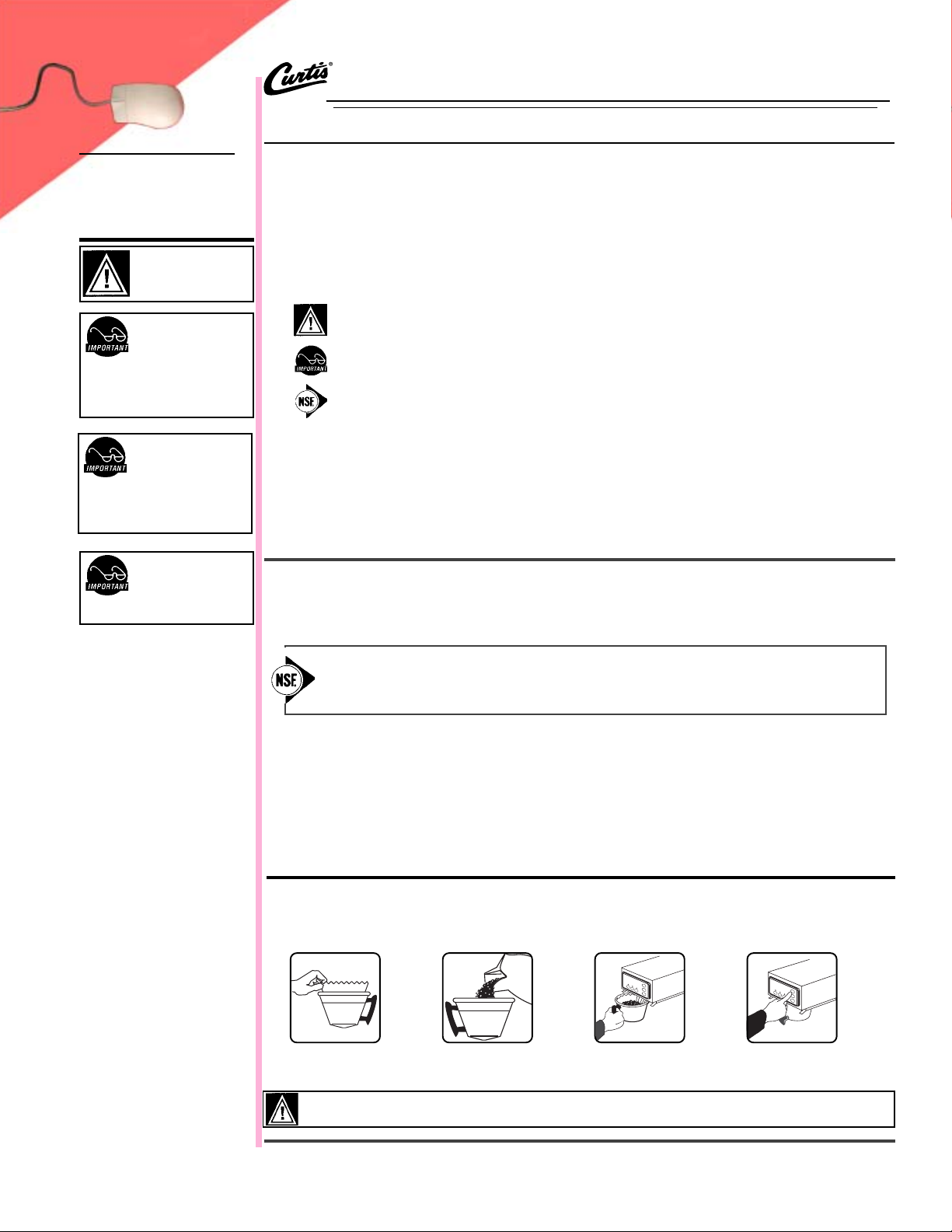
1. Brewer should be ON (Confirm at rear toggle switch, then press the ON/OFF button). Ready-to-Brew should be on the display.
If connected to an InterLock grinder, grinder should be on. If Interlocked, grind coffee at this time.
2. Place an empty Satellite under the brewcone and press the warmer switch to pre-heat the Satellite.
3. Place a clean filter
into the brewcone.
WARNINGWARNING
WARNING TO AVOID SCALDING, Do not remove brewcone while brew light is flashing.
WARNINGWARNING
FOR THE LATEST SPECIFICATIONS AND INFORMATION GO TO
4. Fill brewcone with
ground coffee.
WWW.WILBURCURTIS.COM
5. Transfer filled
brewcone to
brewer.
6. Press Brew button.
Brewing will begin
immediately.
1
Page 2
Quick Start
YY
our Curtis our Curtis
Y
our Curtis
YY
our Curtis our Curtis
After connection to water and power; the rear toggle switch must be on. You will hear a beep sound, indicating power is available to the controller.
The control displays . Press ON/OFF button and the screen will display . After three seconds,
Water will fill the tank (approximately 2-3 minutes depending on water flow rate). When the proper level is reached
screen. It takes approximately 20 minutes to reach setpoint temperature of 200°F.
ADS System is FADS System is F
ADS System is F
ADS System is FADS System is F
CURTIS
actoractor
y Pre-Set for Optimum Py Pre-Set for Optimum P
actor
y Pre-Set for Optimum P
actoractor
y Pre-Set for Optimum Py Pre-Set for Optimum P
erformance.erformance.
erformance.
erformance.erformance.
<GEMINI TWIN>
WILBUR CURTIS
gem TS & GEM SS
CURTIS
is displayed.
FILLING
CURTIS
will appear on the
HEATING
Control will display when temperature reaches the setpoint (200°F). Unit is now ready to brew.
CURTIS
READY TO BREW
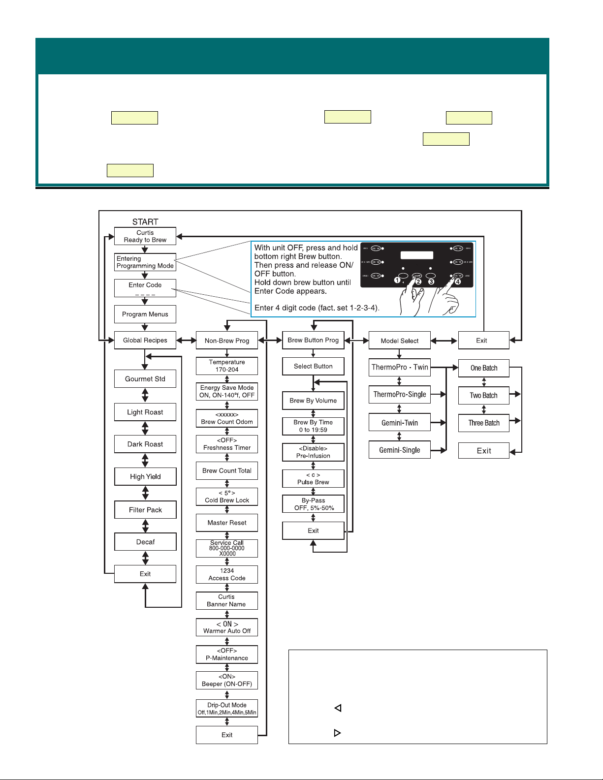
PROGRAM MENUS
IMPORTANT NOTE:
All programming selections are performed with the three center buttons.
The symbols below the buttons are:
Scroll LEFT
SELECTION or ENTER to save new parameter
2
Scroll RIGHT
Page 3

PARTS
DIAGRAMS
23
24
25
33
26
27
28
29
30
31
32
22
1A
10
GEM TS
NN
Part NPart N
Nº
Part Nº
NN
1
2
3
4
5
11
A
12
6
7
13
14
8
9
15
16
17
19
18
20
21
Part NPart N
1
WC-3357
1A
WC-3354
WC-5421
2
3
WC- 844-101
4
WC-37121
WC- 441
5
6
WC-39395
6A
WC-39440
WC-39439
6B
6C
WC-39438
7
WC-37176*
WC-8559
8
9
WC-1809
10
WC-5423
WC- 847
11
12
WC-2977
13
WC-37122
WC- 442
14
15
WC-29050
16
WC-1501
WC- 102
17
18
WC-3765L
19
WC-39462
WC-37102*
20
21
WC-3500
22
WC-5829
WC-54216
23
24
WC-37008
25
WC-5502
WC-5350
26
27
WC-4382
28
WC- 934-04
WC-1438-101
29
30
WC-43055
31
WC- 522
WC-5231
32
33
WC-62015
**
* Recommmended parts to stock.
**
DescriptionDescription
Description
DescriptionDescription
BREWCONE W/HANDLE
BREWCONE, GOURMET LRG CAP
COVER, TOP
**
*
KIT, VALVE BY-PASS NON-ADJUST
**
**
*
KIT, DUMP VALVE LEFT
**
SOLENOID, LOCK BREWCONE LEFT
LABEL, UCM OVERLAY DUAL TWIN
LABEL, CONTL PANEL 3 BATCH
LABEL, CONTL PANEL 2 BATCH
LABEL, CONTL PANEL 1 BATCH
KIT, UCM CONTROL MODULE
RELAY, SOLIDSTATE 40A W/HT SNK
**
*
FAUCET, HOT WATER
**
DECK ASSY NO HEATING ELMTS
**
*
**
VALVE, INLET
FITTING ASSY, SPRAYHEAD
**
*
KIT, DUMP VALVE RIGHT
**
SOLENOID, LOCK BREWCONE RIGHT
SPRAYHEAD, AFS-AMBER
FUSE HOLDER ASSY W5A FUSE
**
*
**
SWITCH, TOGGLE
**
*
KIT, VALVE REPAIR
**
LABEL, BOTTOM PANEL GEMTS
KIT, WARMER ELEMENT
**
*
LEG, 4” ADJUSTABLE
**
COVER, FRONT
TANK ASSY, 7800W-220VAC
**
*
KIT, TANK LID ROUND
**
**
*
PROBE ASSY, WATER LEVEL
**
TUBE, ½” ID x 1/8W SILICONE
GUARD, SHOCK HEATING ELEMENT
**
*
ELEMENT HEATING 2.5KW 220V
**
**
*
**
SENSOR, HEATING TANK
GUARD, SHOCK RESET T-STAT
**
*
THERMOSTAT, RESET
**
**
*
**
COMPOUND, SILICONE
TANK COMPLETE, 7800W-220V
21
22
1
2
19
3
2
20
24
16
17
4
5
6
7
A
29
18
8
9
32
31
GEM SS
NN
Part NPart N
Nº
Part Nº
NN
Part NPart N
WC-5450
1
WC-37122
2
3
WC-39436
WC-39432
3A
10
11
12
13
14
15
WC-39434
3B
4
WC-3357
WC-29050
5
WC-5452
6
7
WC-8559
WC-39448
8
WC-1809
9
10
WC- 847
WC-2401
11
WC-37130
12
13
WC-1501
WC- 102
14
WC-3500
15
16
WC-5451
WC-38310
17
WC-37102
18
19
WC-3765L
WC-37132
20
WC-2977
21
22
WC-37176
WC-5851
23
WC-62014
24
24A
WC-62013
WC-5502-01
25
WC- 522*
26
27
WC-43055
WC- 906-04
28
WC-5350
29
30
WC-43801
WC-1438-101
31
WC-5231
32
**
* Recommmended parts to stock.
**
DescriptionDescription
Description
DescriptionDescription
COVER, TOP
**
*
**
KIT, DUMP VALVE RIGHT
LABEL, CONTROL PANEL 3 BATCH
LABEL, CONTROL PANEL 1 BATCH
LABEL, CONTROL PANEL 2 BATCH
BREWCONE ASSY COMPLETE
**
*
**
SPRAYHEAD, AFS-AMBER
COVER, FRONT
**
*
RELAY, SOLID ST W/INTGRTD HT SNK
**
LABEL, BOTTOM WRAP GEMSS
**
*
**
FAUCET, HOT WATER
**
*
VALVE, INLET 2GPM 120V 10W
**
ELBOW 3/8” NPT x 1/4” FLARE
**
*
**
KIT, VALVE BYPASS
FUSE HOLDER ASSY W/5A FUSE
**
*
**
SWITCH, TOGGLE 125V, 80A
LEG, 4” ADJUSTABLE
WARMER DECK - NO HTG ELMTS
LABEL, CAUTION HOT SURFACE
WARMER ELEMENT
**
*
KIT, VALVE REPAIR
**
**
*
**
KIT, VALVE REPAIR
FITTING ASSY, SPRAYHEAD
**
*
KIT, UCM & LABEL INSTRUCTIONS
**
COVER, TANK W/NOTCHES
TANK COMPLETE 4KW 220V
TANK COMPLETE 3.2KW 120/220V
PROBE ASSY, WATER LEVEL
THERMOSTAT, RESET
SHOCK GUARD, RESET THERMOSTAT
**
*
**
HEATING ELEMENT, 2000W 220V
TUBE, ½” ID x 1/8W SILICONE
SHOCK GUARD, HEATING ELEMENTS
**
*
**
SENSOR, TEMP HEATING TANK
**
*
**
COMPOUND, SILICONE 3/4 OZ TUBE
3
Page 4

ELECTRICALELECTRICAL
ELECTRICAL
ELECTRICALELECTRICAL
SCHEMASCHEMA
SCHEMA
SCHEMASCHEMA
GEM TS
TICTIC
TIC
TICTIC
4
Page 5

ELECTRICAL
SCHEMATIC
GEM SS
NC
5
Page 6

Product Warranty Information
The Wilbur Curtis Company certifies that its products are free from defects in material and workmanship under normal use. The following limited warranties
and conditions apply:
3 Years, Parts and Labor, from Original Date of Purchase on digital control boards.
2 Years, Parts, from Original Date of Purchase on all other electrical components, fittings and tubing.
1 Year, Labor, from Original Date of Purchase on all electrical components, fittings and tubing.
Additionally, the Wilbur Curtis Company warrants its Grinding Burrs for Forty (40) months from date of purchase or 40,000 pounds of coffee, whichever
comes first. Stainless Steel components are warranted for two (2) years from date of purchase against leaking or pitting and replacement parts are
warranted for ninety (90) days from date of purchase or for the remainder of the limited warranty period of the equipment in which the component is
installed.
All in-warranty service calls must have prior authorization. For Authorization, call the Technical Support Department at 1-800-995-0417. Effective date
of this policy is April 1, 2003.
Additional conditions may apply. Go to www.wilburcurtis.com to view the full product warranty information.
CONDITIONS & EXCEPTIONS
The warranty covers original equipment at time of purchase only. The Wilbur Curtis Company, Inc., assumes no responsibility for substitute replacement
parts installed on Curtis equipment that have not been purchased from the
Wilbur Curtis Company, Inc. The Wilbur Curtis Company will not accept any responsibility if the following conditions are not met. The warranty does not
cover and is void under the following circumstances:
1) Improper operation of equipment: The equipment must be used for its designed and intended purpose and function.
2) Improper installation of equipment: This equipment must be installed by a professional technician and must comply with all local electrical,
mechanical and plumbing codes.
3) Improper voltage: Equipment must be installed at the voltage stated on the serial plate supplied with this equipment.
4) Improper water supply: This includes, but is not limited to, excessive or low water pressure, and inadequate or fluctuating water flow rate.
5) Adjustments and cleaning: The resetting of safety thermostats and circuit breakers, programming and temperature adjustments are the
responsibility of the equipment owner. The owner is responsible for proper cleaning and regular maintenance of this equipment.
6) Damaged in transit: Equipment damaged in transit is the responsibility of the freight company and a claim should be made with the carrier.
7) Abuse or neglect (including failure to periodically clean or remove lime accumulations): Manufacturer is not responsible for variation in
equipment operation due to excessive lime or local water conditions. The equipment must be maintained according to the manufacturer’s
recommendations.
8) Replacement of items subject to normal use and wear: This shall include, but is not limited to, light bulbs, shear disks, “0” rings, gaskets,
silicone tube, canister assemblies, whipper chambers and plates, mixing bowls, agitation assemblies and whipper propellers.
9) Repairs and/or Replacements are subject to our decision that the workmanship or parts were faulty and the defects showed up under normal
use. All labor shall be performed during regular working hours. Overtime charges are the responsibility of the owner. Charges incurred by delays,
waiting time, or operating restrictions that hinder the service technician’s ability to perform service is the responsibility of the owner of the
equipment. This includes institutional and correctional facilities. The Wilbur Curtis Company will allow up to 100 miles, round trip, per in-warranty
service call.
RETURN MERCHANDISE AUTHORIZATION: All claims under this warranty must be submitted to the Wilbur Curtis Company Technical Support
Department prior to performing any repair work or return of this equipment to the factory. All returned equipment must be repackaged properly in
the original carton. No units will be accepted if they are damaged in transit due to improper packaging. NO UNITS OR PARTS WILL BE AC-
CEPTED WITHOUT A RETURN MERCHANDISE AUTHORIZATION (RMA). RMA NUMBER MUST BE MARKED ON THE CARTON OR
SHIPPING LABEL. All in-warranty service calls must be performed by an authorized service agent. Call the Wilbur Curtis Technical Support
Department to find an agent near you.
WILBUR CURTIS CO., INC.
6913 Acco St., Montebello, CA 90640-5403 USA
Phone: 800/421-6150 Fax: 323-837-2410
Technical Support Phone: 800/995-0417 (M-F 5:30A - 4:00P PST) E-Mail: techsupport@wilburcurtis.com
Web Site: www.wilburcurtis.com
6
Printed in U.S.A. 9/05 . F-3373-S . rev B
9/13/05 @ 8.9 . ecn 7731
11/17/04 @ 12.0 . ECN 7141
9/29/04 @ 13.4 . edr 4146
 Loading...