

Page 1
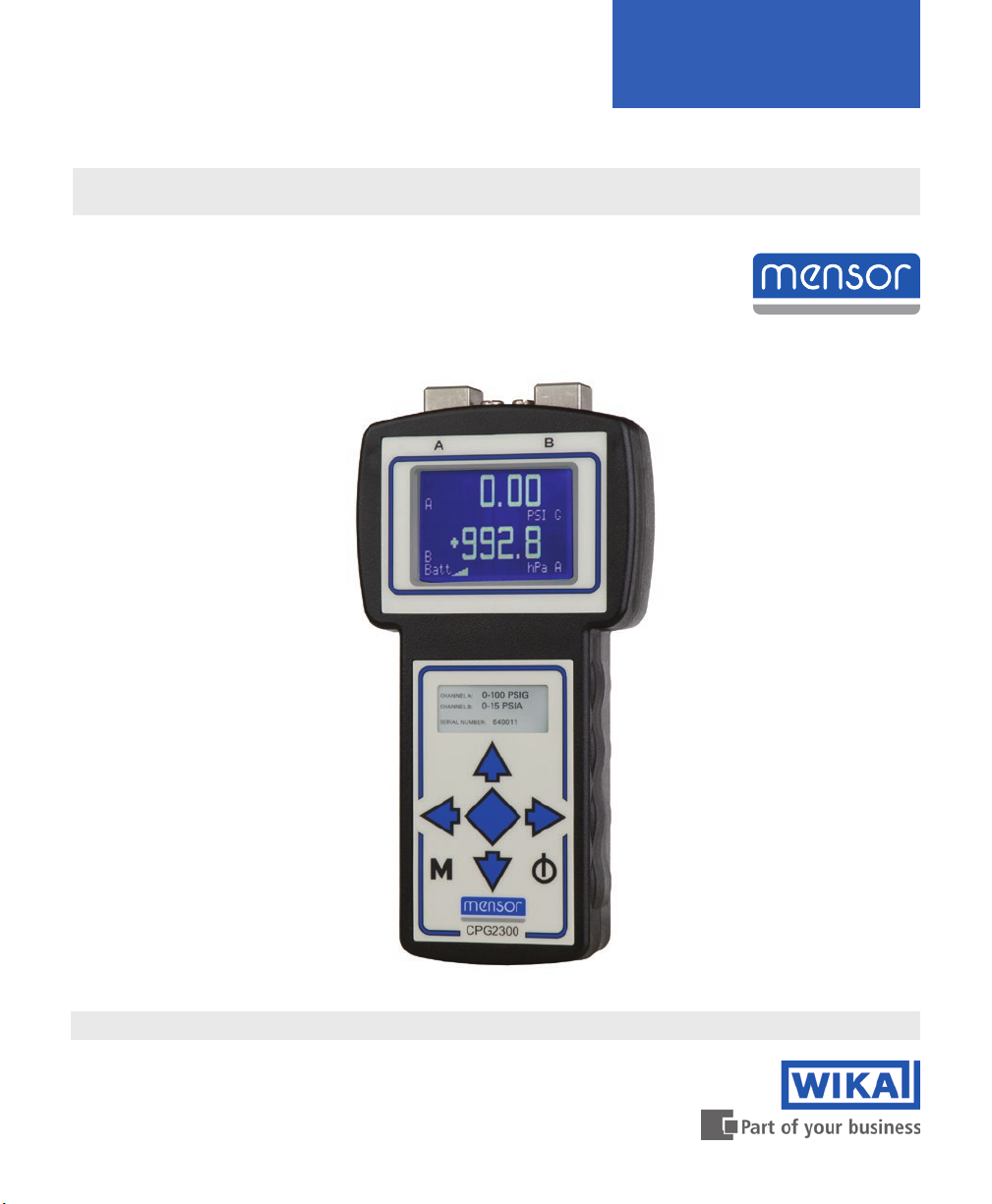
Portable Digital Pressure Gauge
CPG2300
Operating Instructions
Portable Digital Pressure Gauge Series 2300 PN 0017441003N • 01/2017
Page 2
Portable Digital Pressure Gauge
CPG2300 Series
This Warning symbol indicates that danger of injury for persons
and the environment and/or considerable damage (mortal danger,
!
Warning
!
Caution
danger of injury) will occur if the respective safety precautions are
not taken.
This Caution symbol indicates danger for the system and
material if the respective safety precautions are not taken.
This Notice symbol does not indicate safety notices but
information for a better understanding of the facts.
Copyright © 2005, Mensor. All rights reserved.
2 Operating Instructions CPG2300 Series
Page 3

Portable Digital Pressure Gauge
CPG2300 Series
Table of Contents
1. General Information 5
1.1 Warranty 5
1.2 Important Notice 5
1.3 Software License Agreement 6
1.4 Mensor Service Plus 6
1.4.1 After the Warranty 6
1.4.2 Calibration Services 6
1.4.3 Certications and Accreditations 6
2. Safety Notices 7
2.1 Warnings and Caution Notices 7
3. Product Description 9
3.1 General Description 9
3.2 Display 9
3.3 Power Supply 9
3.4 Battery 9
3.5 Serial In/Out Communications 10
4. Specications 11
5. Installation 13
5.1 Unpacking the Instrument 13
5.2 Dimensions 14
5.3 Pressure Connections 15
5.4 Electrical Connections 16
5.5 Power On 16
6. Local Operation 17
6.1 Keypad 17
6.2 Standard Display 18
6.3 Menu Screens 18
6.3.1 Main Menu Screen 18
6.3.2 Sensor Setup Menu 19
6.3.3 Password Entry Screen 21
6.3.4 Sensor Calibration Screen 21
6.3.5 Units Screens 23
Operating Instructions CPG2300 Series 3
Page 4

Portable Digital Pressure Gauge
CPG2300 Series
6.4 Menu Tree 24
7. Remote Operation 25
7.1 General 25
7.2 Communication Syntax and Command Conventions 25
7.2.1 Password Protection 26
7.2.2 Response String Format 26
7.2.3 Commands and Queries 27
7.2.4 User Programmable Pressure Units List 30
7.2.5 Pressure Unit Codes and Conversions 31
8. Options 33
8.1 Current Input 33
8.1.1 Menu Screens 33
8.1.2 Operational Notes 35
8.1.3 Connection Congurations 36
8.1.4 Application Diagrams 37
9. Calibration 39
9.1 Environment 39
9.2 Equipment 39
9.3 Pressure Standard 41
9.4 Calibration Medium 41
9.5 Calibration Process 41
9.5.1 Zero Adjustment 41
9.5.2 Span Adjustment 42
4 Operating Instructions CPG2300 Series
Page 5

Portable Digital Pressure Gauge
CPG2300 Series
1. General Information
1.1 Warranty
All products manufactured by Mensor are warranted to be free of defects in workmanship
and materials for a period of one year from the date of shipment. No other express
warranty is given, and no armation of Seller, by words or actions, shall constitute a
warranty. SELLER DISCLAIMS ANY IMPLIED WARRANTIES OF MERCHANTABILITY
OR FITNESS FOR ANY PARTICULAR PURPOSES WHATSOEVER. If any defect in
workmanship or material should develop under conditions of normal use and service
within the warranty period, repairs will be made at no charge to the original purchaser,
upon delivery of the product(s) to the factory, shipping charges prepaid. If inspection
by Mensor or its authorized representative reveals that the product was damaged
by accident, alteration, misuse, abuse, faulty installation or other causes beyond the
control of Mensor, this warranty does not apply. The judgment of Mensor will be nal
as to all matters concerning condition of the product, the cause and nature of a defect,
and the necessity or manner of repair. Service, repairs or disassembly of the product
in any manner, performed without specic factory permission, voids this warranty.
MENSOR MAKES NO WARRANTY OF ANY KIND WITH REGARD TO THIS
MANUAL, INCLUDING, BUT NOT LIMITED TO, THE IMPLIED WARRANTIES OF
MERCHANTABILITY AND FITNESS FOR A PARTICULAR PURPOSE. Mensor
shall not be liable for errors contained herein or for incidental or consequential
damages in connection with the furnishing, performance, or use of this material.
1.2 Important Notice
The product specications and other information contained in this manual are subject to
change without notice.
Mensor has made a concerted eort to provide complete and current information for the
proper use of the equipment. If there are questions regarding this manual or the proper
use of the equipment, contact either Mensor or WIKA:
Mensor WIKA Alexander Wiegand SE & Co. KG
201 Barnes Drive Alexander-Wiegand-Straße 30
San Marcos, Tx 78666 D-63911 Klingenberg / Germany
Tel: 1.512.396.4200 Tel: (+49) 93 72/132-9986
1.800.984.4200 (USA only) Web Site: www.wika.de
Web Site: www.mensor.com Fax: (+49) 93 72/132-8767
Fax: . 512.396.1820 E-Mail: [email protected]
E-Mail: [email protected]
[email protected]
Operating Instructions CPG2300 Series 5
Page 6

Portable Digital Pressure Gauge
CPG2300 Series
1.3 Software License Agreement
This product contains intellectual property, i.e., software programs, that are licensed for
use by the end user/customer (hereinafter “end user”).
This is not a sale of such intellectual property.
The end user shall not copy, disassemble or reverse compile the software program.
The software programs are provided to the end user “as is” without warranty of any kind,
either express or implied, including, but not limited to, warranties of merchantability and
tness for a particular purpose. The entire risk of the quality and performance of the software program is with the end user.
Mensor and its suppliers shall not be held to any liability for any damages suered or
incurred by the end user (including, but not limited to, general, special, consequential or
incidental damages including damages for loss of business prots, business interruption,
loss of business information and the like), arising from or in connection with the delivery,
use or performance of the software program.
1.4 Mensor Service Plus
If you have problems and you don’t nd the answer in this manual, contact Mensor at
1.800.984.4200 (USA only) or 1.512.396.4200 for personal assistance, or at any of the
contact addresses listed on the rear cover of this manual. We are ready to help.
1.4.1 After the Warranty
Mensor’s concern with the performance of this instrument is not limited to the warranty pe-
riod. We provide complete repair, calibration and certication services after the warranty
for a nominal fee.
1.4.2 Calibration Services
In addition to servicing our own products Mensor can perform a complete pressure calibration service, up to 20,000 psi, for all of your pressure instruments. This service includes
an accredited calibration.
1.4.3 Certications and Accreditations
Mensor is registered to ISO 9001:2008. The calibration program at Mensor is accredited
by A2LA, as complying with both the ISO/IEC 17025:2005 and the ANSI/NCSL Z540-11994 standards.
6 Operating Instructions CPG2300 Series
Page 7
Portable Digital Pressure Gauge
CPG2300 Series
2. Safety Notices
2.1 Warnings and Caution Notices
WARNING: NOT EXPLOSION PROOF!
!
Warning
!
Caution
!
Caution
Installation of this instrument in an area requiring devices rated as
intrinsically safe is not recommended.
CAUTION: Some ranges require clean, non-corrosive pressure
media. See “Media Compatibility” in Section 4, Specications. This
instrument is not designed for oxygen use.
CAUTION: Avoid excessive overpressure to the sensor! Externally
mounted relief valves to provide overpressure protection are available from Mensor as optional devices, and are highly recommended
for very low pressure sensors (less than 10 psi).
CAUTION: It is recommended that a backup wrench be used when
!
Caution
installing ttings or connections on the CPG2300.
CAUTION: Use of a power supply other than the one provided by
Mensor will invalidate the warranty.
!
Caution
CAUTION: ESD PROTECTION REQUIRED.
The proper use of grounded work surfaces and personal wrist
straps are required when coming into contact with exposed circuits
(printed circuit boards) to prevent static discharge to sensitive
electronic components.
Additional notices are found throughout this manual.
Operating Instructions CPG2300 Series 7
Page 8

Portable Digital Pressure Gauge
CPG2300 Series
Notes
8 Operating Instructions CPG2300 Series
Page 9

Portable Digital Pressure Gauge
CPG2300 Series
3. Product Description
3.1 General Description
The CPG2300 Digital Pressure Gauge is a portable battery powered instrument that
provides very high accuracy pressure measurements. This instrument utilizes very high
stability silicon sensors that are electronically compensated for pressure linearity over the
entire operating temperature range. The CPG2300 also has a standard RS-232 serial port
that can be used for remote communications.
Dierent models are available including the Model 2310 (single channel) and the Model
2320 (dual channel). These channels are referred to as Channel A and Channel B, and
can operate independent of each other. Viewed from the front, Channel A is the sensor on
the top left of the instrument and can be ordered with any available pressure range (see
the Specications section). Channel B is the sensor on the top right of the instrument and
can be ordered with pressure ranges from 5 to 1000 psig (7.5 to 1000 psia).
Additionally, the CPG2300 can be equipped with optional current measurement from 4 to
20 mA and a 24V dc loop power. See the Options section for more information.
3.2 Display
Several dierent display screens are presented while operating the CPG2300. Each
screen is arranged into blocks of information, generally organized into columns and rows.
These screens are each described in further detail in the Local Operation and Remote
Operation sections.
3.3 Power Supply
The power adapter is utilized to provide power to operate the CPG2300 and also to recharge the internal batteries. It produces 12 Vdc @ 830 mA max.
3.4 Battery
The CPG2300 has an internal battery pack consisting of four ‘AA’ nickel-metal hydride batteries. The battery pack is replaceable and can be ordered from Mensor.
In pressure measurement mode the CPG2300 will operate approximately 20 hours on a
fully charged new battery. There is a battery level indicator on the display that indicates the
battery charge level. The battery level indicator will blink when there is approximately one
hour of battery left. The unit will automatically shut o when the battery reaches a predetermined level.
Operating Instructions CPG2300 Series 9
Page 10

Portable Digital Pressure Gauge
CPG2300 Series
Battery Charging: The CPG2300 has a built-in battery charger that will take approximately
8 hours with an input supply of 12 Vdc to fully recharge a battery. The built-in charger
will switch from fast charge to maintenance mode automatically when a full charge is
achieved. It is acceptable to leave the wall transformer connected to AC power indenitely.
Charge Voltage vs. Temperature: The battery can be charged over an ambient temperature range of 0 to 40 degrees C with a supply voltage of 9 to 12 Vdc.
3.5 Serial In/Out Communications
The serial port is congured as RS-232, 9600 baud, 8 data bits, 1 stop bit and no parity. It
is designed as a 9-pin DCE device, so that a straight pin to pin cable can be used to con-
nect it to a standard PC serial port. The serial port can be used to congure and calibrate
the CPG2300 or to read the output of its sensors.
Wiring requirements are provided in the Installation section and a list of valid commands
and responses (Table 7.2.3) is provided in the Remote Operation section.
10 Operating Instructions CPG2300 Series
Page 11
Portable Digital Pressure Gauge
CPG2300 Series
4. Specications
Accuracy specications presented herein are obtained by comparison with primary
standards traceable to the National Institute of Standards and Technology (NIST). These
specications are obtained in accordance with the ISO Guide to the Expression of Uncertainty in Measurement (GUM). The calibration program at Mensor is accredited by the
American Association of Laboratory Accreditation (A2LA) as complying with both the ISO/
IEC 17025:2005 and the ANSI/NCSL Z540-1-1994 standards.
Mensor reserves the right to change specications without notice.
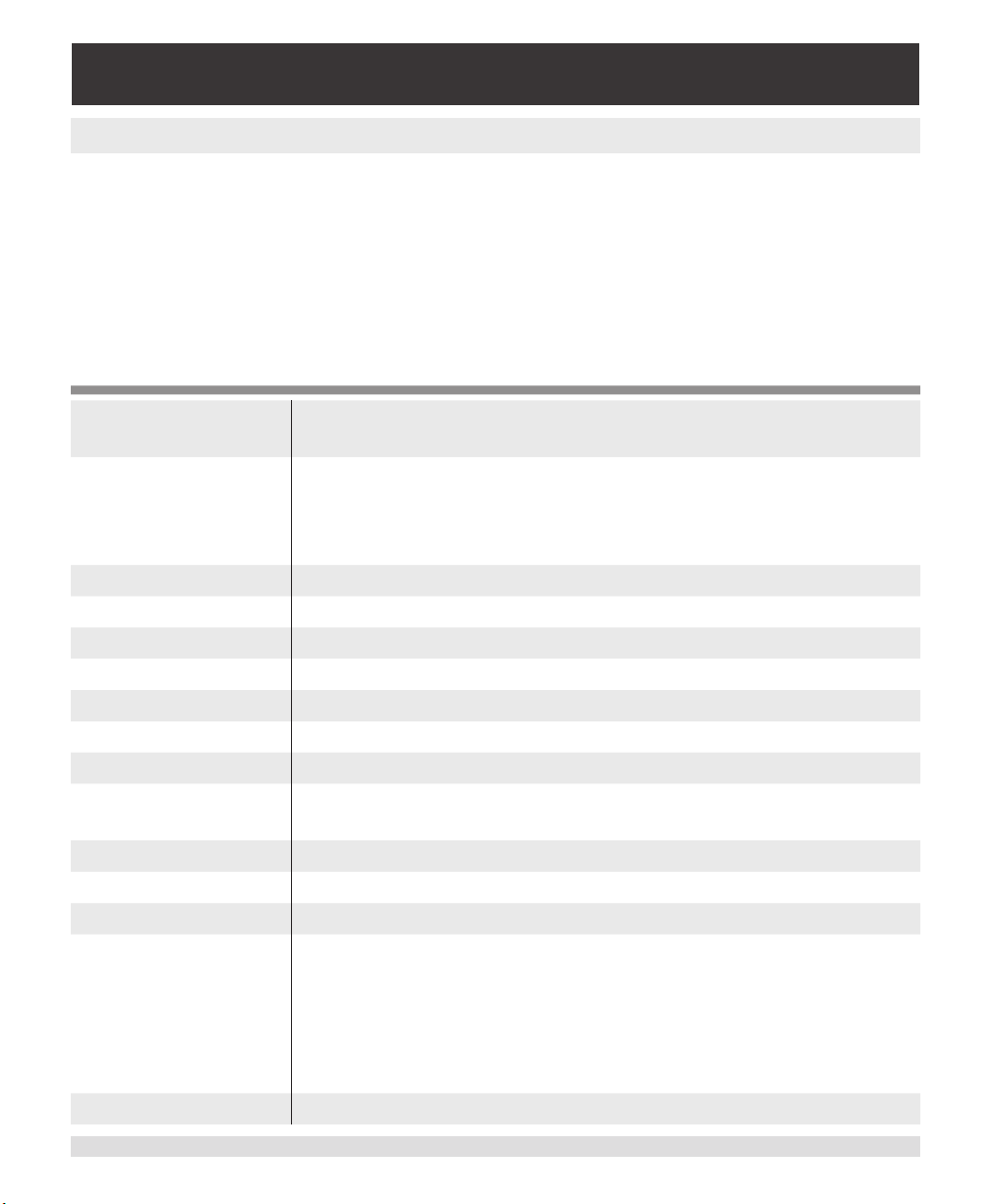
Total Uncertainty 0.015% FS for ranges ≥1 psig (0.030% FS for ranges <1 psig)
over the compensated temperature range for 180 days.
Pressure Ranges Channel A: 7.5 to 6015 psia
0.36 to 6000 psig
Channel B: 7.5 to 1000 psia
5 to 1000 psig
Calibration Interval 180 days
Resolution 5 digits on display; 6 digits over serial port
Overpressure Limit 1.5 x span
Storage -20 ... 70ºC
Warmup <1 minute
Reading Rate ~4.6 / second
Response Time <252 mS
Orientation Negligible >30 psi, zero oset resettable with zero calibration or
null function.
Communications RS-232, 9600 baud,N,8,1
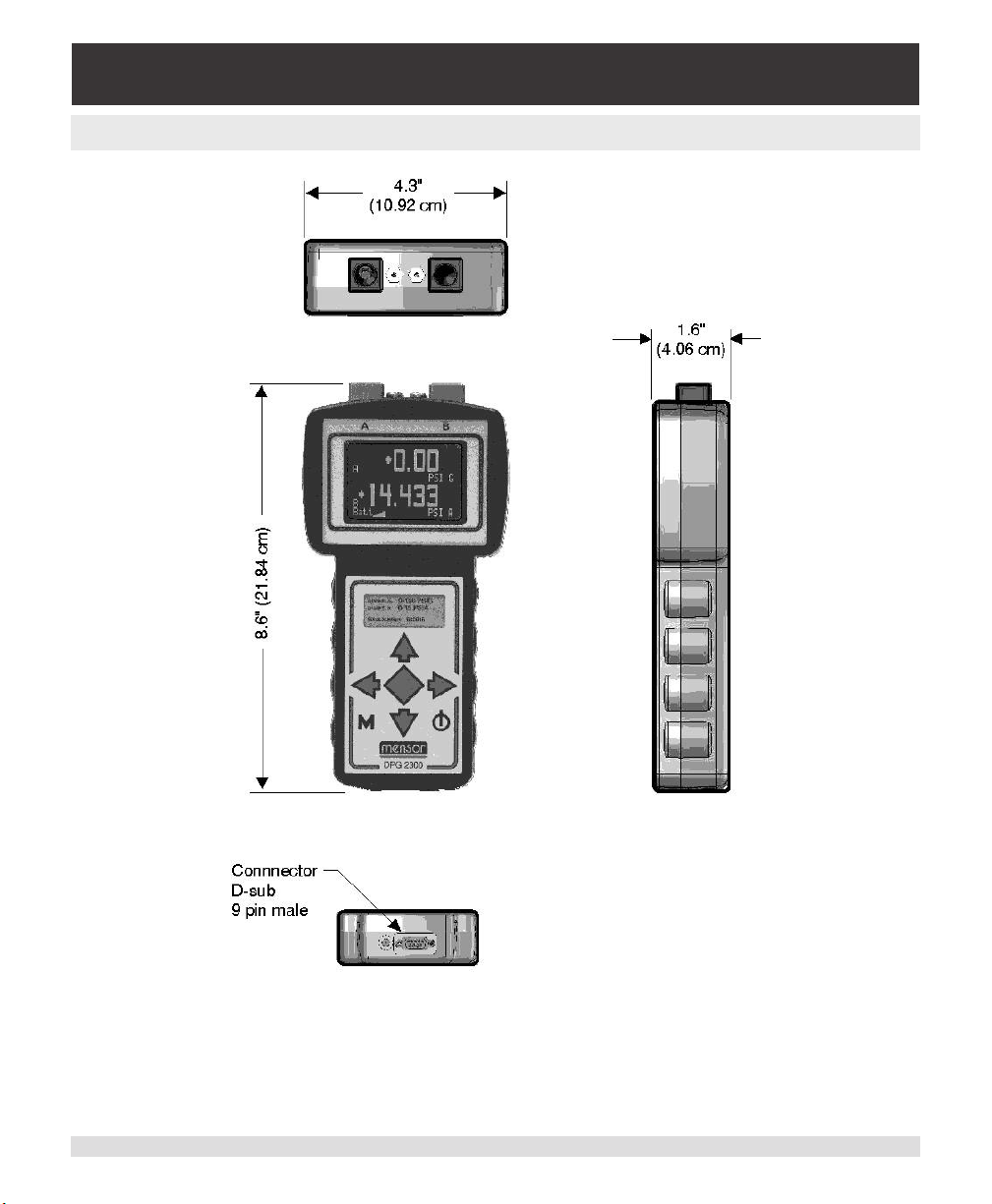
Case size T-shaped, 8.6 inches H x 4.3 inches W x 1.6 inches D
Weight 1.5 lbs.
Media
Compatibility
Battery Life 20 hours
Pressure port: Clean, dry, non-corrosive, non-combustible,
non-oxidizing gases for all ranges. Ranges ≥ 5 psi: Media com-
patible with aluminum, 316 SS, Buna N, Viton, silicone grease
and RTV. Cannot guarantee accuracy on media other than
gases. Not designed for oxygen service.
Reference port: Clean, dry, non-corrosive gases.
Operating Instructions CPG2300 Series 11
Page 12
Portable Digital Pressure Gauge
CPG2300 Series
Recharge Time 8 hours max.
Power
Requirements
Fittings 1/4 inch FNPT pressure ports, nom. 1/16 inch hose barb for ref
Warranty One year
Options Carrying pouch - attaches to belt
Current Input Option Battery life: ~4 hours with loop power @ 20mA, and 10 hours
Units psi, inHg @0C and 60F, inH2O @4C, 20C, bar, mbar, mmHg @
Display Monochrome 128 x64 LCD, with white LED back light.
+9 to +14.5 Vdc, 830mA max for battery recharge.
ports.
Hand pump
Relief valves (mounted externally)
with loop power @ 4mA.
Current measurement: 4 to 20 mA (calibrated).
Loop power voltage: 24V unregulated.
Current uncertainty: 0.03% of R.
0C, cmHg @0C, hPa, kPa, Pa, MPa, kg/sq cm, cmH2O @4C,
cmH2O @20C, mSW @0C.
12 Operating Instructions CPG2300 Series
Page 13

Portable Digital Pressure Gauge
CPG2300 Series
5. Installation
5.1 Unpacking the Instrument
In addition to functional testing, each unit is inspected for appearance prior to leaving the
factory. Upon receipt, please examine the transducer for shipping damage. Report any apparent damage to the carrier immediately.
In addition to this manual you should have:
• CPG2300 Digital Pressure Gauge;
• Power adapter (charger)
• Any accessories ordered;
• An envelope containing the Calibration Certicate.
Operating Instructions CPG2300 Series 13
Page 14
Portable Digital Pressure Gauge
CPG2300 Series
5.2 Dimensions
Figure 5.2 - Case Outline/Dimensions
14 Operating Instructions CPG2300 Series
Page 15
Portable Digital Pressure Gauge
CPG2300 Series
5.3 Pressure Connections
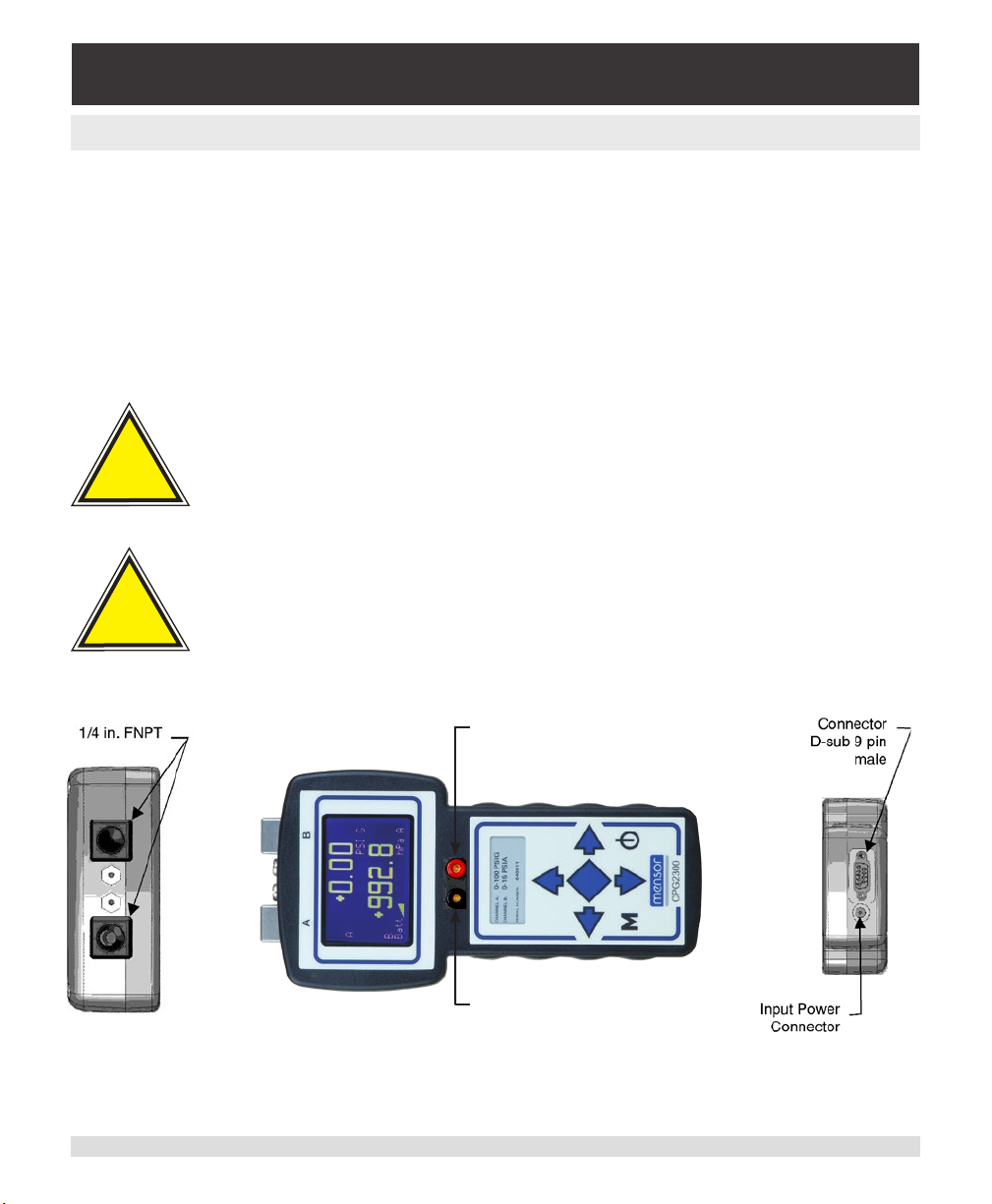
The left 1/4 inch FNPT threaded port is used to measure the pressure on Channel A of the
CPG2300. If the sensor range is less than 20 psi and is a gauge or bi-directional sensor,
there will also be a 1/16 inch hose barb tting beside the pressure port. The barb tting
provides access to the reference port of the sensor.
If the CPG2300 has a second pressure sensor installed, it will have a second 1/4 inch
FNPT threaded port on the right to measure the pressure on Channel B. If its range is less
than 20 psi and it is a gauge sensor, a barb tting provides access to the reference port of
the sensor.
CAUTION: Avoid excessive overpressure to the sensor! Externally
!
Caution
mounted relief valves to provide overpressure protection are available from Mensor as optional devices, and are highly recommended
for very low pressure sensors (less than 10 psi).
!
Caution
Operating Instructions CPG2300 Series 15
CAUTION: It is recommended that a backup wrench be used when
installing ttings or connections on the CPG2300.
Sense +
INPUT JACK (red)
Sense INPUT JACK (black)
(for Input Current Option)
Figure 5.3 - Pressure and Electrical Connections
Page 16
Portable Digital Pressure Gauge
CPG2300 Series
5.4 Electrical Connections
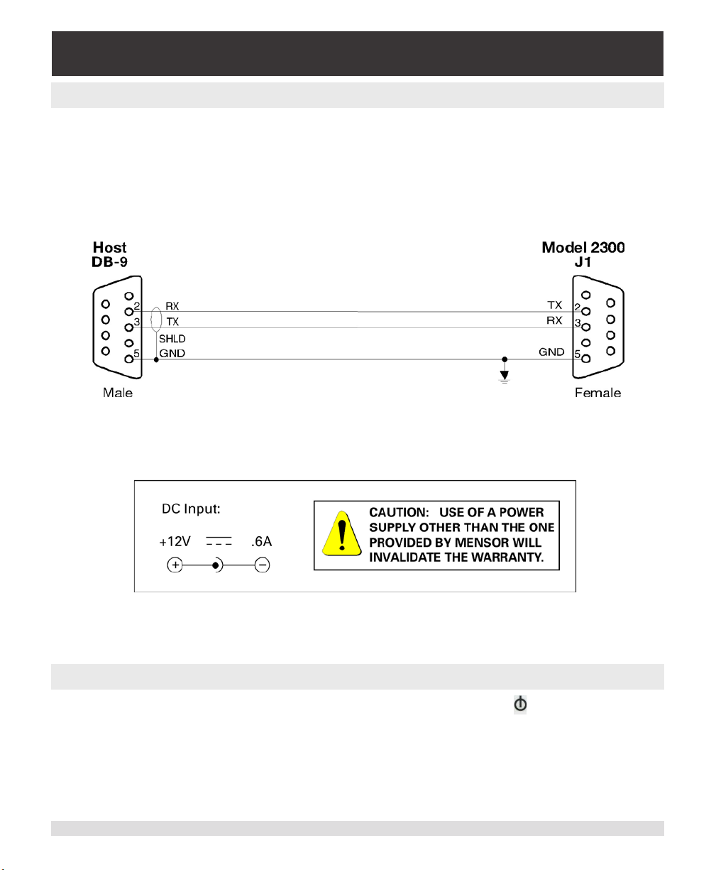
For RS-232 serial port operation, connect the CPG2300 to the host computer per Figure
5.4a. Notice that the host TRANSMIT line is connected to the CPG2300 RECEIVE line
(TX to RX), and vice versa.
The power connector is a 2.1 mm standard power jack. The center pin is +12 Vdc and the
outside is ground (see Figure 5.4b).
Figure 5.4a - RS-232 Hookup
Figure 5.4b - DC Input
5.5 Power On
After the pressure connections are secure, press the power switch ( ). The CPG2300
will run through a brief initialization sequence and then will display the sensor channel(s)
that was active when turned o last.
16 Operating Instructions CPG2300 Series
Page 17
Portable Digital Pressure Gauge
CPG2300 Series
6. Local Operation
6.1 Keypad
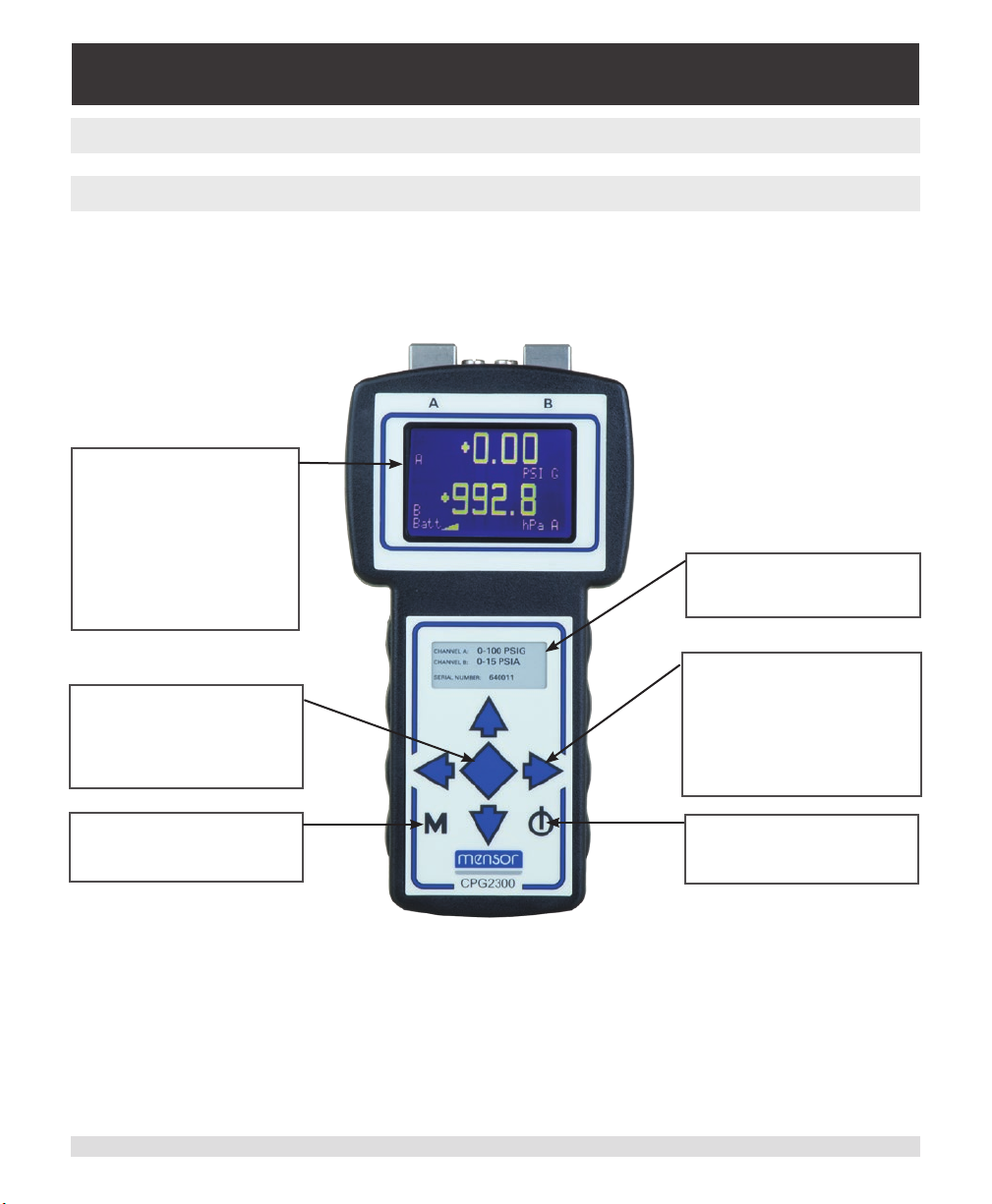
A brief description of the keypad features and the display is provided below in Figure 6.1,
“Keypad and Display Features”.
Display Screen
Displays user data and menu
setup screens to access or
change various functions.
The standard display screen
(shown) provides user info for
the active sensor channel(s),
pressure reading(s), engineering unit(s) and battery level.
Label
The label lists the serial number
and pressure ranges.
Arrow Keys (4)
The “Enter” Key
The central ◆ key is used
as an enter key to select the
highlighted menu choice or for
single button null.
The “Main Menu” Key
The M key beings up the main
menu.
The four arrow keys typically
provide navigation in the menus.
They are also used to adjust the
displayed pressure for calibration adjustment and adjustment
of the programmable user unit.
Power Switch
This key is the power on/o
switch.
Figure 6.1 - Keypad and Display Features
Operating Instructions CPG2300 Series 17
Page 18
Portable Digital Pressure Gauge
CPG2300 Series
6.2 Standard Display
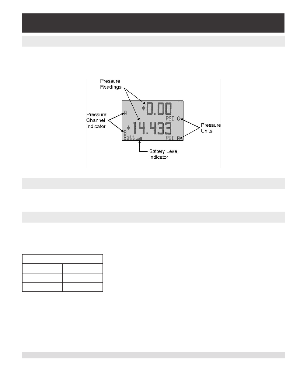
When the CPG2300 is powered on, the sensor channel(s) that was active when the
CPG2300 was turned o previously will be displayed after the initialization screen. The
standard display screen is shown below.
Figure 6.2 - Standard Display Screen
6.3 Menu Screens
All the menu screens can be navigated by use of the arrow keys. To select a menu item,
highlight the item and press the ◀┘ (enter) key.
6.3.1 Main Menu Screen
If the M (menu) key is pressed at any time, the main menu is displayed on the screen. If
one sensor is installed in the CPG2300, the Sensor A setup screen is displayed. If two
sensors are installed in the CPG2300, the following will be displayed:
Main Menu
Sensor A A Setup
Sensor B B Setup
Sensor A&B
The items in this menu perform the following functions when selected:
Sensor A: Displays only the A Sensor.
Sensor B: Displays only the B Sensor.
Sensor A&B: Displays both the A and the B Sensor.
Sensor A setup: Displays the Sensor A setup screen.
Sensor B setup: Displays the Sensor B setup screen.
18 Operating Instructions CPG2300 Series
Page 19
Portable Digital Pressure Gauge
CPG2300 Series
6.3.2 Sensor Setup Menu
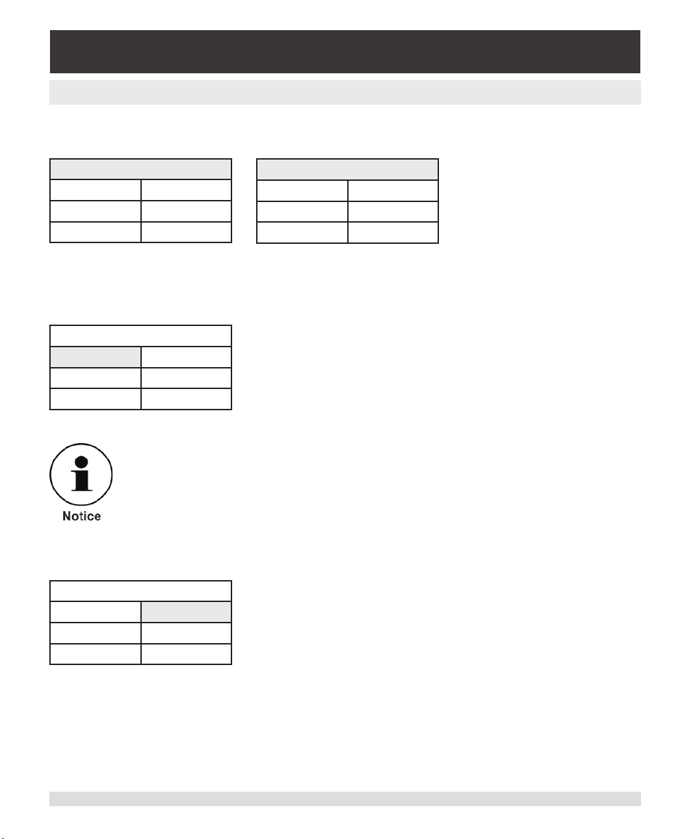
Both the Sensor A and Sensor B setup menu screens are identical. These menus allow
setup of various functions for the selected sensor.
A Setup
Peak O Peak Rst
Null O Cal
Units
Peak O Peak Rst
Null O Cal
B Setup
Units
The items in this menu perform the following functions when selected:
Peak O (On): Toggles the peak indicator for the active sensor.
A Setup
Peak On Peak Rst
Null O Cal
Units
The current condition of the peak indicator is displayed.
If the menu item displays “Peak O”, the peak indicator is
disabled for the active sensor. If “Peak O” is selected, it
will enable peak capture for the active sensor. If the Sensor Setup menu is re-entered, the menu item will display
“Peak On” to indicate that the peak capture function is
enabled.
Peak readings are displayed only when a single channel is selected.
Peak Reset: Resets the peak values to the active measured pressure.
A Setup
Peak O Peak Rst
Null O Cal
Units
Operating Instructions CPG2300 Series 19
Page 20
Portable Digital Pressure Gauge
CPG2300 Series
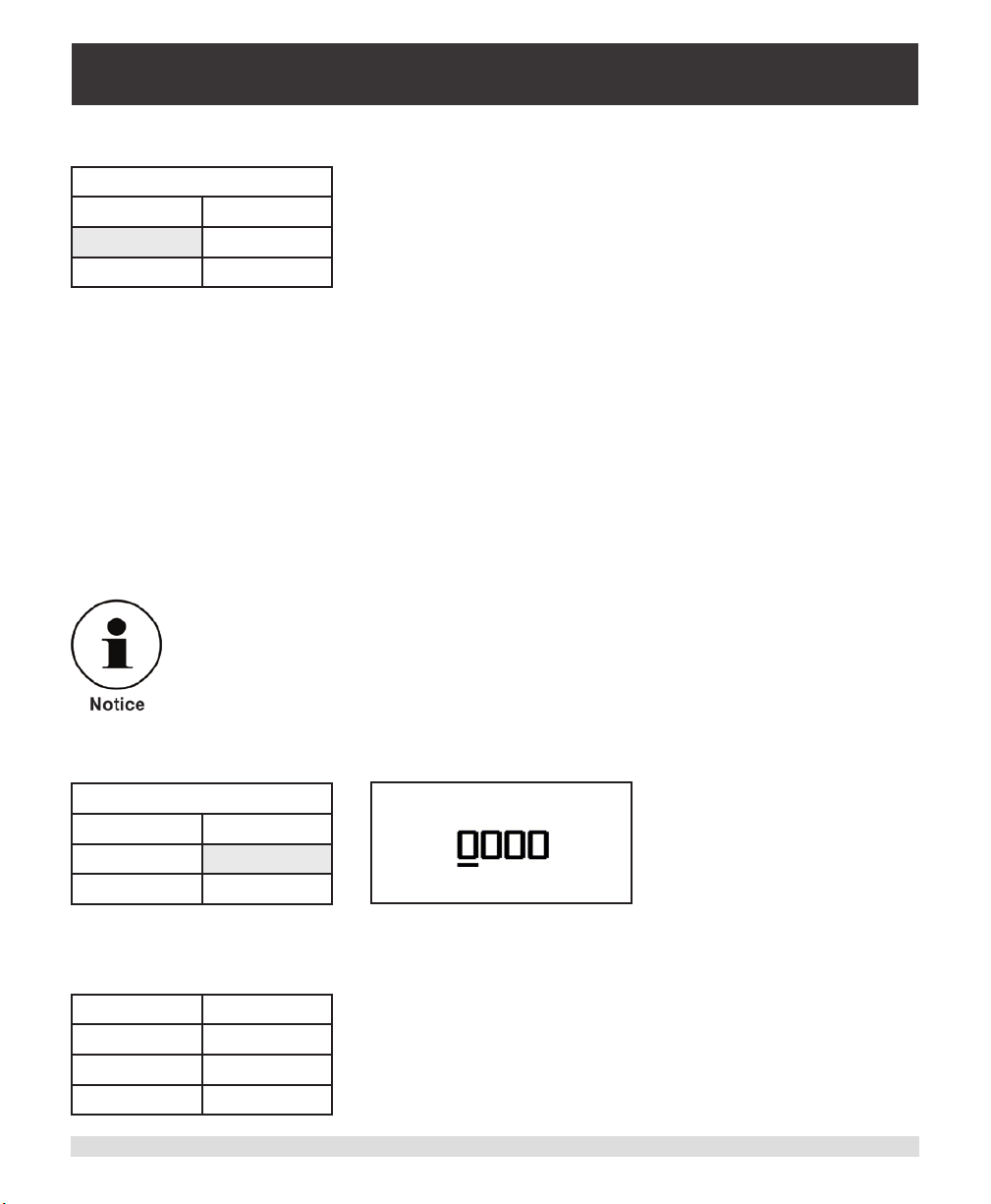
Null O (On): Toggles the null function for the active sensor.
A Setup
Peak O Peak Rst
Null On Cal
Units
The current state of the null function is displayed. If the
menu item displays “Null O”, the null function is disabled
for the active sensor. If “Null O” is selected, the CPG2300
will subtract the current measured pressure from any
subsequent pressure readings. Unlike the Peak function,
the Null function can be displayed on the main operation
screen with both sensors pressures displayed. A capital
“N” appears just above the “A” or “B” on the main operation
screen to indicate that the sensor channel is currently
using a null oset.
Single button null: The null feature can also be accessed by pressing the ◀┘ (enter)
key while at the standard Display. When both channels are displayed, pressing the null
button once will null channel A. Pressing the null button a second time will null channel B.
Pressing the null button a third time will un-null channel A and a fourth press will un-null
channel B. When a single channel is displayed the null button will toggle nulling on or o.
The instrument will revert to the un-nulled state if power is cycled.
1. Peak and Null functions can be used simultaneously.
2. Pressure units must not be changed when using the null feature.
Cal: Displays the calibration password entry screen.
A Setup
Peak O Peak Rst
Null O Cal
Units
Sensor A Calibration
Password Entry
Enter to Continue
Units: Displays the rst of the three units screens.
PSI InHg 0c
InHg 60f InH20 4c
InH20 20c mBAR
BAR more
20 Operating Instructions CPG2300 Series
Page 21
Portable Digital Pressure Gauge
CPG2300 Series
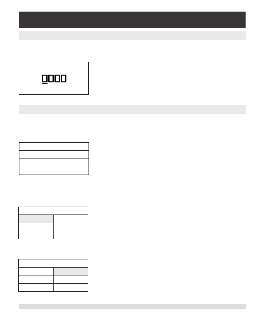
6.3.3 Password Entry Screen
If the calibration function is selected from the sensor setup screen, the password entry
screen will be displayed:
Sensor A Calibration
Password Entry
The four digit password can be entered by moving the
cursor with the left and right arrow keys under the digit to
be changed and then pressing the up or down arrow keys
Enter to Continue
to scroll through the numbers 0 to 9. When the password
is entered, press the ◀┘ (enter) key. The active channel’s
calibration screen will be displayed.
6.3.4 Sensor Calibration Screen
The sensor calibration screen allows the zero and span of the active sensor to be adjusted, the calibration to be reset to the factory defaults, and the calibration password to be
changed.
A Calibration
Cal Zero Cal Span
Change PW Reset Cal
The items in the calibration menu perform the following functions when selected:
Cal Zero: Displays the measured pressure for the active sensor.
MA Calibration
Cal Zero Cal Span
Change PW Reset Cal
Adjust the digits to the true pressure applied to the active
sensor and press the ◀┘ (enter) key to store the value. For
more details, see the Calibration section.
Cal Span: Displays the measured pressure for the active sensor.
MA Calibration
Cal Zero Cal Span
Change PW Reset Cal
Operating Instructions CPG2300 Series 21
Adjust the digits to the true pressure applied to the active
sensor and press the ◀┘ (enter) key to store the value.
For more details, see the Calibration section.
Page 22
Portable Digital Pressure Gauge
CPG2300 Series
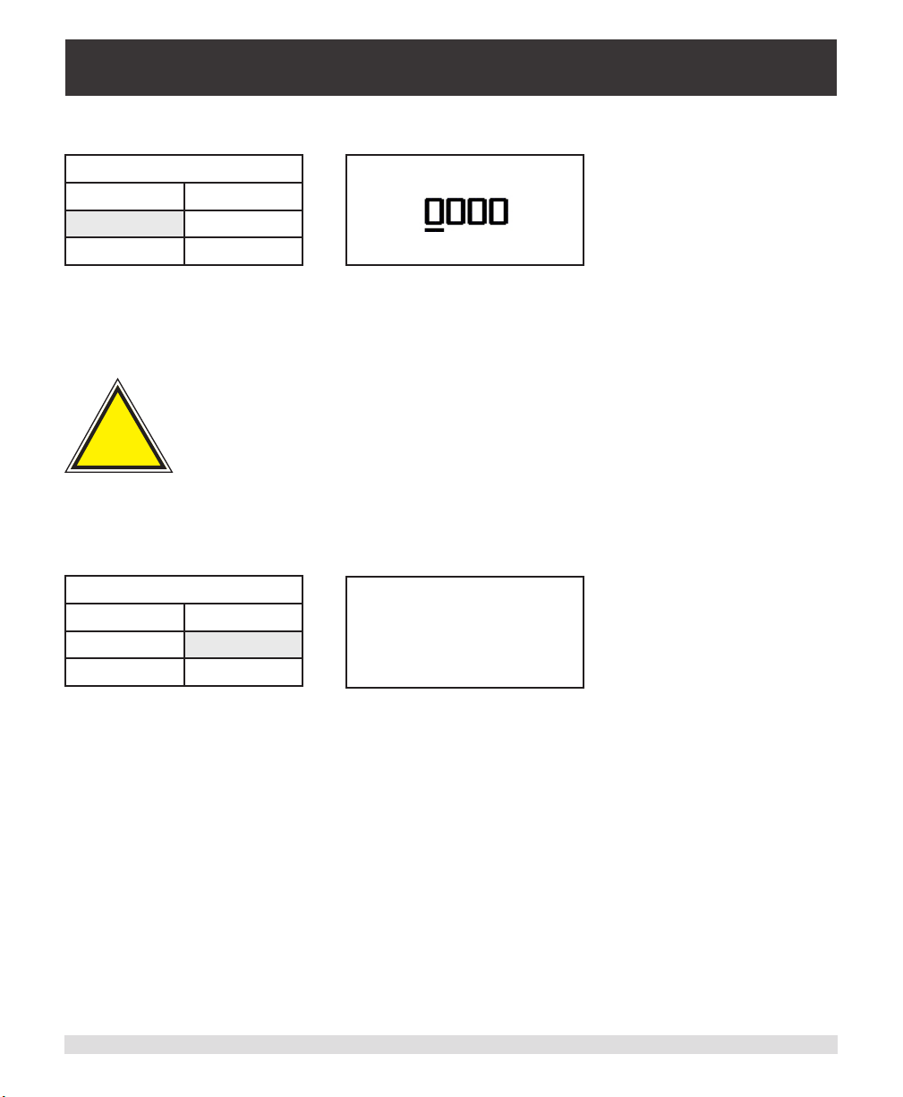
Change Password:
A Calibration
Cal Zero Cal Span
Change PW Reset Cal
Sensor A Calibration
Password Entry
Enter to Continue
Move the cursor with the left and right arrow keys under the digit to be changed. Increment
the digit with the up and down arrow keys. When the password has been changed, press
the ◀┘ (enter) key to store it. The main menu is then displayed.
The password is set to “0000” at the factory. When making a change
!
write it down and save the number. If the password is lost contact
Mensor.
Caution
Reset Cal: Displays a conrmation screen.
A Calibration
Cal Zero Cal Span
Change PW Reset Cal
Reset Calibration
Sensor B
Are you Sure?
Enter to Reset
Other Keys to Quit
If the ◀┘ (enter) key is pressed, the calibration is reset to the factory defaults and the main
operation screen is displayed. If any other key is pressed, the main menu screen is displayed.
22 Operating Instructions CPG2300 Series
Page 23
Portable Digital Pressure Gauge
CPG2300 Series
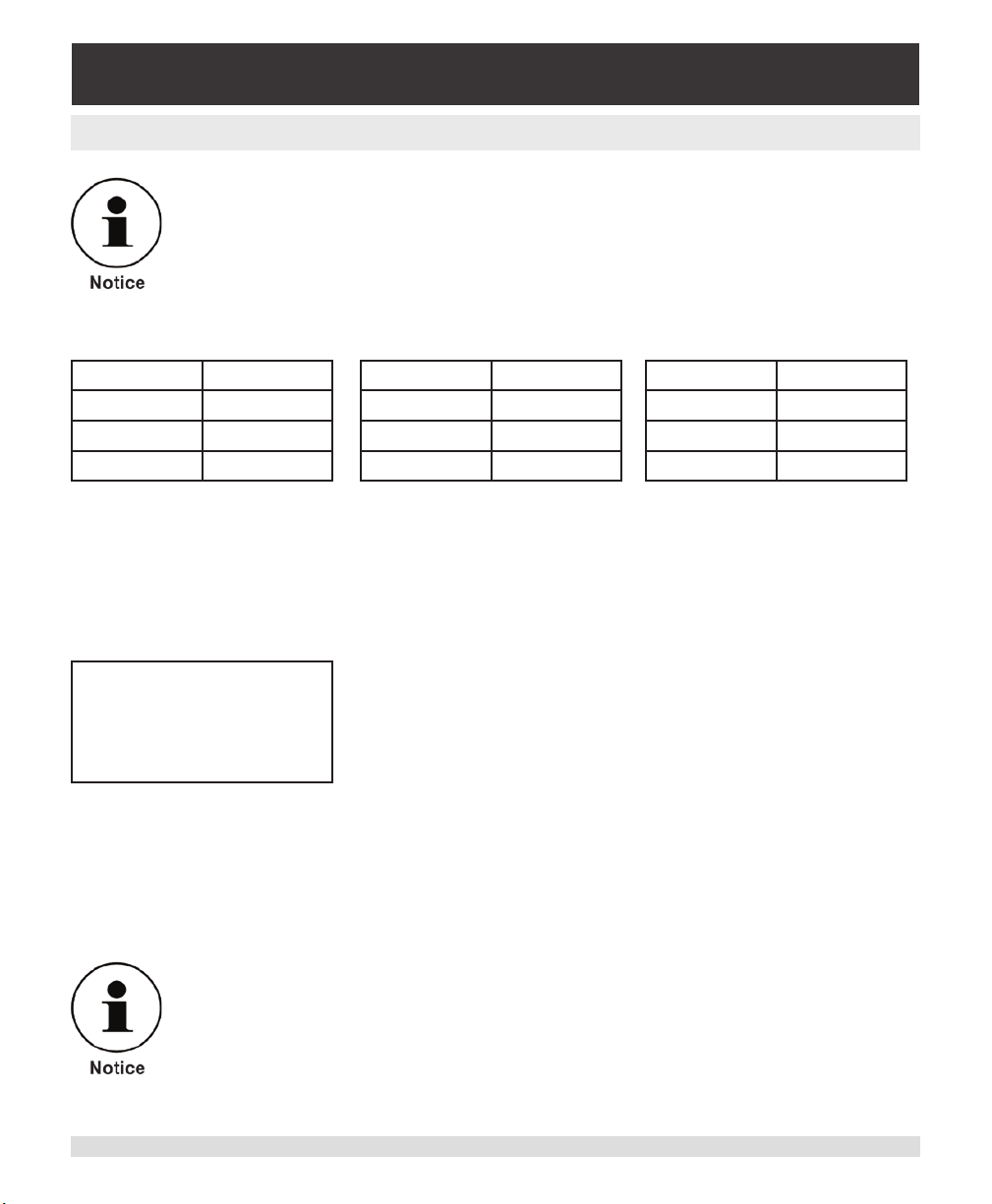
6.3.5 Units Screens
Pressure units must not be changed when using the null feature.
There are three units screens that allow selection of the most common pressure units:
PSI InHg 0c
InHg 60f InH20 4c
InH20 20c mBAR
BAR more
mmHg 0c cmHg 0c
Pa hPa
kPa mPa
ks/cm^2 more
cmH20 4c cmH20 20c
MSW User
Set User more
The pressure unit of the active sensor is selected by highlighting the desired unit and
pressing the ◀┘ (enter) key. To advance to the next units screen, select “more”. The last
units screen allows selection and entry of a special “User” unit. The User unit has a cong-
urable conversion factor that converts from PSI to the desired value. To enter the conversion factor, select “Set User” on the last units screen to display:
Set User Units A
+1.00000e+1
Enter to Continue
Use the left and right arrow keys to move the cursor under the digit to change and the
up and down arrow keys to increment the digit. The conversion factor can be set from
-1.00000e+6 to -1.00000e-6 and +1.00000e-6 to +1.00000e+6. Press the ◀┘ (enter) key
to store the conversion factor. To apply the “user” conversion factor, the units “User” must
be selected for the active sensor.
For the remote programmable pressure units list and information,
see “User Programmable Pressure Units List” in the Remote
Operation section of this manual.
Operating Instructions CPG2300 Series 23
Page 24
Portable Digital Pressure Gauge
CPG2300 Series
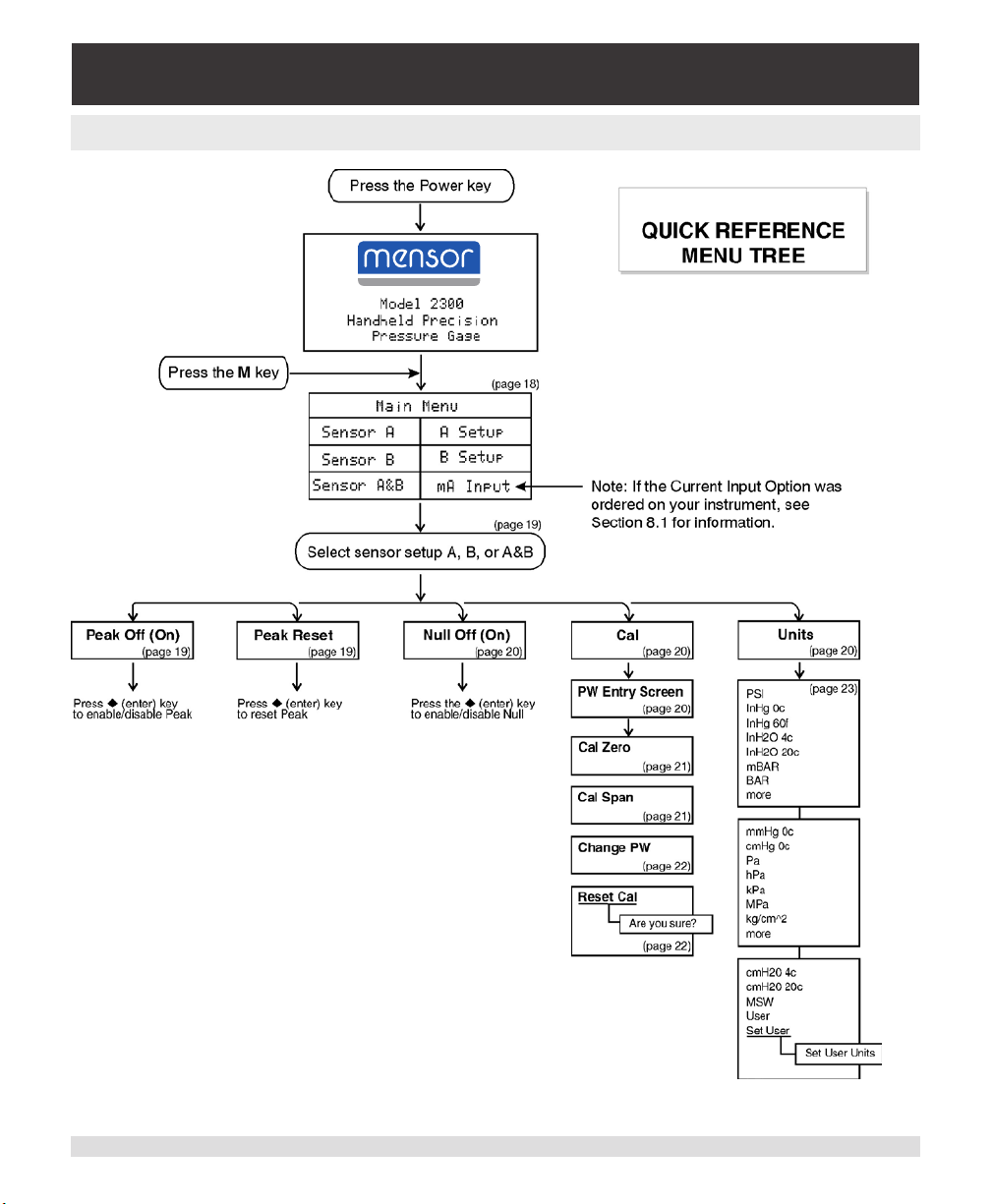
6.4 Menu Tree
CPG2300
Figure 6.4 - CPG2300 Menu Tree
24 Operating Instructions CPG2300 Series
Page 25

Portable Digital Pressure Gauge
CPG2300 Series
7. Remote Operation
7.1 General
The CPG2300 can be operated from a remote computer which communicates over a
standard RS-232 serial port. The serial port can be used to congure and calibrate the
CPG2300, or to read the output of its sensors. This section of the manual provides in-
formation on the serial port conguration, explains the command conventions used in
this manual, and lists the common commands and queries which are recognized by the
CPG2300.
7.2 Communication Syntax and Command Conventions
All commands and responses are in ASCII characters. The lower and upper case are
interpreted the same. Every command or query begins with the pound symbol (#). The
question mark (?) character is signicant to the CPG2300. All other punctuation characters are ignored. Some commands require a password string. A carriage return (<cr>) and/
or linefeed (<lf>) must terminate each command or query. The global address character is
an asterisk (*). It can be sent in place of the actual CPG2300 address.
All of the commands are channel dependent. If sensor A is selected by sending #XCH A,
all subsequent queries and commands work on channel A until #XCH B is sent. The active
channel should always be checked before sending commands, as the channel status can
be controlled by keypad also. Upon power-on the active channel is dependent on pressure display. Channel B is active when sensor B only is displayed. For all other pressure
displays (A or A&B) the Channel A is active. In the case of a single channel unit, Channel
A is always active.
It is good practice to query for the active channel before sending commands that change
a sensors operating parameters. See Table 7.2.3 for commands and queries.
Operating Instructions CPG2300 Series 25
Page 26

Portable Digital Pressure Gauge
CPG2300 Series
7.2.1 Password Protection
Certain commands require a password to be sent before a setting is changed. The pass-
word is only eective for the next command, so the password must be sent immediately
before any password protected command string. The password string is the password set
in the CPG2300. The password is set at the factory to “0000”. However, for calibration protection, the actual password has been replaced with PW in the command string example.
7.2.2 Response String Format
All strings sent by the CPG2300 are terminated by a carriage return <cr> and linefeed
<lf>.The CPG2300 will return an “R” character (ASCII 82) to indicate that it has received
a valid command or password rather than a query. If an invalid command or password is
sent, the “R” character will not be returned. When communicating with the CPG2300, the
“R” character must be received before sending additional commands or queries. In the
event that an invalid command could be sent, a time-out period of approximately one second should be used before sending the next command or query.
The full command word is shown in Table 7.2.3 in all capital letters. Other conventions
used to describe commands are shown in Table 7.2.2.
Table 7.2.2 - Command Conventions
Conven-
Description
tion
X Address (single character 0 through 9 or A through Z; case insensitive)
* Global address character
? Query operator
<sp> Space ( )
PW Password (insert password in place of PW; case insensitive)
N One character place holder for digit or decimal point
n...n Variable length eld
R Ready response
26 Operating Instructions CPG2300 Series
Page 27
Portable Digital Pressure Gauge
CPG2300 Series
7.2.3 Commands and Queries
i
Each command that changes a parameter is volatile until the SAVE
command is issued.
Notice
Table 7.2.3 - Command Set
Pass-
word
Protect
No ? #X?<cr><lf> The return string from a pressure reading query”?” can
Command
/ Query
Command String Return String Description
have dierent formats dependent upon how the unit is set
up. If the LCD display is displaying sensors A & B and the
“DSP?” query returns 3, the return string will return two
values. The rst is sensor A and the second is sensor B.
Example format: 0 -0.001, +14.4561<cr><lf>
If the LCD display is displaying either sensor A or B only
and the “DSP?” query returns 1 or 2, the return string will
return a single value from the selected sensor.
Example format: 1 +14.4711<cr><lf>
If the peak function is enabled the return string will contain
three values. The rst value is the maximum pressure, the
second is the present pressure and the third is the minimum pressure. This return string is representative of the
active channel. Note that when both channels are selected
(“DSP?” = 3) the A & B readings are returned.
Example of the peak return string format: 1 +14.7011,
+14.4561, +14.3001<cr><lf>.
No A #XA<sp>n<cr><lf> R Sets address of CPG2300 to 0-9
or A-Z.
No CH? #XCH?<cr><lf> X<sp>n<cr><lf> Returns active channel “A” or “B”.
No CH #XCH<sp>n<cr>
<lf>
No CPW #XCPW<sp>nn
nn<cr><lf>
Operating Instructions CPG2300 Series 27
R Sets active sensor channel where
n is A or B.
R Enter customer password.
Page 28

Portable Digital Pressure Gauge
CPG2300 Series
No CSC? #XCSC?<cr><lf> X<sp>n.nnn<cr><lf> Available only with the Current
Input option.
Returns span correction multiplier
for current measurement.
Ye s CSC #XCSC<sp>n.nnn
<cr><lf>
No CZC? #XCZC?<cr><lf> X<sp>n.nnn<cr><lf> Available only with the Current
Ye s CZC #XCZC<sp>n.nnn
<cr><lf>
No DC? #XDC?<cr><lf> X<sp>DC<sp>nn
Ye s DC #XDC<sp>nnnnnn
<cr><lf>
No DSP? #XDSP?<cr><lf> X<sp>DSP<sp>N
No DSP #XDSP<sp>n<cr>
<lf>
No FL? #XFL?<cr><lf> X<sp>FL<sp>nn
No FL #XFL<sp>nn
<cr><lf>
No FS? #XFS?<cr><lf> X<sp>FS<sp>nnnnn
No I? #XI?<cr><lf> X<sp>nn.nnn<cr><lf> Available only with the Current
No ID? #XID?<cr><lf> X<sp>ID<sp>nn
No NOS? #XNOS?<cr><lf> X<sp>NOS<sp>n
R Available only with the Current
Input option.
Sets span correction multiplier for
current measurement.
Ranges from .95 to 1.05.
Input Option.
Returns the zero oset for the current measurement.
R Available only with the Current
Input Option.
Sets the zero oset for current
measurement.
Ranges from +/- .8 mA.
Returns the date of calibration
nnnn<cr><lf>
R Loads the date of calibration
<cr><lf>
R Loads display mode where
<cr><lf>
R Sets the lter percentage ranges
<cr><lf>
MENSOR, <sp>nnnn
64nn,<sp>nnnnnnnn,
<sp>Vn.nn<cr><lf>
<cr><lf>
where nnnnnn is mmddyy.
where nnnnnn is mmddyy.
Returns display mode where
1 = Sensor A, 2 = Sensor B,
3 = Sensors A&B
1 = Sensor A, 2 = Sensor B,
3 = Sensors A&B
Returns the lter percentage.
from 0 to 99.
Returns the CPG2300 accuracy.
Measurement option;
Returns current measurement in
milliamps.
Returns the CPG2300 ID string.
Returns number of sensors installed in the CPG2300.
28 Operating Instructions CPG2300 Series
Page 29

Portable Digital Pressure Gauge
CPG2300 Series
No NULL? #XNULL?<cr><lf> X<sp>NULL<sp>n
<cr><lf>
No NULL #XNULL<sp>n<cr>
<lf>
No PEAK? #XPEAK?<cr><lf> X<sp>PEAK<sp>n
No PEAK #XPEAK<sp>n
<cr><lf>
No R-? #XR-?<cr><lf> X<sp>R-<sp>nnnnn
No R+? #XR+?<cr><lf> X<sp>R+<sp>nnnnn
No RST<sp> #XRST<sp><cr>
<lf>
No SAV E #XSAVE<cr><lf> R Saves all data to memory.
No SC? #XSC?<cr><lf> X<sp>SC<sp>nnn
Ye s SC #XSC<sp>nnnnnn
<cr><lf>
Ye s SCPW #XSCPW<sp>nnnn
<cr><lf>
No T? #XT?<cr><lf> X<sp>T<sp>n<cr>
No U? #XU?<cr><lf> X<sp>U<sp>nn<cr>
No U #XU<sp>nn<cr><lf> R Sets the units code for the active
No USR? #XUSR?<cr><lf> X<sp>USR<sp>nn
No USR #XUSR<sp>n
<cr><lf>
R Sets null mode on or o for cur-
<cr><lf>
R Sets peak mode on or o for cur-
<cr><lf>
<cr><lf>
R Resets peak values for the active
nnnn<cr><lf>
R Sets the span correction
R Sets the customer password.
<lf>
<lf>
nnnnnnnennnn
<cr><lf>
R Sets user selected units for the
Returns mode status of active
sensor for null where
n = 0 = OFF, n =1 = ON
rent channel where n = 0 = OFF, n
= 1 = ON.
Returns mode status of active
sensor for peak capture where
n = 0 = OFF, n = 1 = ON
rent channel where n = 0 = OFF, n
= 1 = ON.
Returns minimum pressure range
of active sensor in PSI.
Returns maximum pressure range
of active sensor in PSI.
sensor. A space must be included
after the RST command.
Returns the span correction
multiplier for the active sensor.
multiplier for the active sensor.
Returns the pressure type for the
active sensor; A = Absolute,
G = Gauge, B = Bi-directional.
Returns pressure unit code.
For a complete list of pressure
unit codes and conversions, see
Table 7.2.5.
sensor.
Returns the user unit multiplier for
the active sensor.
active sensor.
Ranges from -1.00000e+6 to
-1.00000e-6 and from +1.00000e6 to +1.00000e+6.
Operating Instructions CPG2300 Series 29
Page 30
Portable Digital Pressure Gauge
CPG2300 Series
No UT? #XUT?<cr><lf> X<sp>UT<sp>N,
<sp>N,<sp>N,...
<cr><lf>
No UT #XUT<sp>N<sp>
N<cr><lf>
No ZC? #XZC?<cr><lf> X<sp>ZC<sp>nn
Ye s ZC #XZC<sp>nnnnnn
<cr><lf>
R Loads the programmable units
nnnnn<cr><lf>
R Sets the zero oset for the active
Returns the list of programmed
pressure units.
list. The rst number is the sequential position in the list from 0
to 7 and the second number is the
unit code as according to Table
7.2.5.
Returns the zero oset for the active sensor.
sensor.
7.2.4 User Programmable Pressure Units List
The remote command UT can be used to modify the default pressure units available on
the units display screen. The user can select from one to eight units to be displayed by
sending a sequence of “UT” commands. The syntax is as follows:
#*UT<sp>n<sp>n<cr><lf> where the rst “n” is a value from 0 to 7 and represents the
units sequential position in the displayed list. The second “n” represents the unit code from
Table 7.2.5. If the rst (0) unit in the sequence is assigned a value of “0” then the displayed
units will default to all the available units from the factory. To display less than eight units, a
“0” is assigned to the next unit in the sequence.
An example of the use of the “UT” command:
#*UT 0 1<cr><lf> - assigns the rst unit displayed as PSI
#*UT 1 2<cr><lf> - the next unit displayed would be InHg 0C
#*UT 2 34<cr><lf> - the third unit displayed would be hPa
#*UT 3 0<cr><lf> - terminates the displayed units to this point
#*UT 0 0<cr><lf> - allows all factory units to be displayed and used
The “SAVE” command must be sent to make changes permanent.
30 Operating Instructions CPG2300 Series
Page 31

Portable Digital Pressure Gauge
CPG2300 Series
7.2.5 Pressure Unit Codes and Conversions
Table 7.2.5 - Pressure Unit Codes and Conversions
Code Pressure Unit PSI Conversion Factor
0 Counts N/A
1 psi 0
2 inHg 0C 2.036020
3 inHg 60F 2.041772
4 inH2O 4C 27.680672
5 inH2O 20C 27.729767
14 bar 0.06894757
15 mbar 68.94757
17 cmH2O 4C 70.3089
19 mmHg 0C 51.71508
20 cmHg 0C 5.171508
22 kPa 6.894757
23 Pa 6894.757
26 kg/sq cm 0.07030697
27 mSW 0C (@3.5% salinity) 0.6838528
34 hPa 68.94757
36 MPa 0.006894757
38 cmH2O 20C 70.4336
99 User User settable
Operating Instructions CPG2300 Series 31
Page 32

Portable Digital Pressure Gauge
CPG2300 Series
Notes
32 Operating Instructions CPG2300 Series
Page 33
Portable Digital Pressure Gauge
CPG2300 Series
8. Options
8.1 Current Input
The current input option is capable of measuring current from 3 to 24 milliamps (mA). The
calibrated range is from 4 to 20 mA. The CPG2300 also provides a 24V dc loop power
source which can be turned on or o and that will power most transmitters. The CPG2300
current measurement is protected from over-current or high voltage up to 50V. It also has
circuitry to prevent damage if the loop power is enabled and the input terminals are shorted. To preserve battery life, the current measurement mode and loop power are turned
o through a power cycle. The input section is protected from over-current or high voltage
input by a comparator controlled mosfet that will limit the current to a nominal of 24.8 mA.
When the resident loop power is enabled, the current limiter circuit will protect the instrument if the input terminals are shorted together.
8.1.1 Menu Screens
Main Menu: The current input is set up using the “mA Input” selection in the main menu.
This menu item will not be displayed unless the current input option is installed. Select the
setup screen by pressing the ◀┘ (enter) key.
Main Menu
Sensor A A Setup
Sensor B B Setup
Sensor A&B mA Input
mA Input Setup: The items in this menu perform the following functions when selected:
mA Input Setup
Display mA O
Source V O
Calibrate mA
Display mA O (On): Enables/disables current measurement by toggling the enter key.
mA Input Setup
Display mA On
Source V O
Calibrate mA
Operating Instructions CPG2300 Series 33
Page 34
Portable Digital Pressure Gauge
CPG2300 Series
Source V O (On): Enables/disables 24V loop power source by toggling the enter key.
mA Input Setup
Display mA O
Source V On
Calibrate mA
Calibrate mA: Displays the calibration password entry screen.
mA Input Setup
Display mA O
Source V O
Calibrate mA
Password Entry Screen: If the calibrate mA function is selected from the mA Input Setup
screen, the password entry screen will be displayed:
mA Calibration
Enter to Continue
mA Calibration Screen: The mA calibration screen allows zero and span to be adjusted, the calibration to be reset to the factory defaults or the calibration password to be
changed.
MA Calibration
Cal Zero Cal Span
Change PW Reset Cal
34 Operating Instructions CPG2300 Series
Page 35
Portable Digital Pressure Gauge
CPG2300 Series
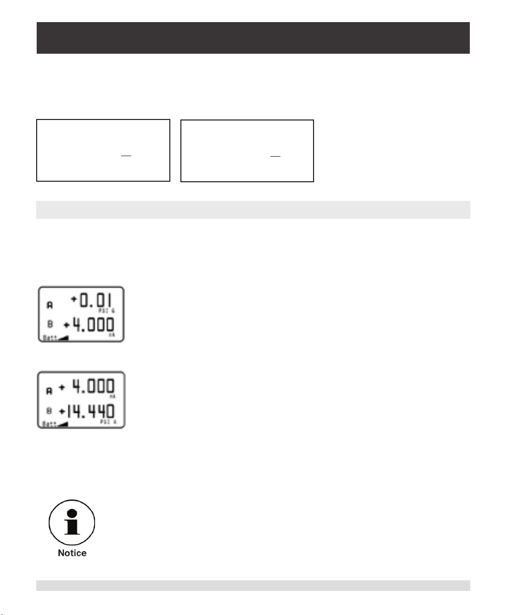
Cal Zero and Cal Span Screens: Digits are selected by using the right or left arrow keys.
The selected digit has a cursor below it. Adjustments of the digit is by the up or down arrow keys. Current input zero and span adjustments are limited to 5% of the range (16 mA).
This would be +/- 0.8 mA. Press enter key to store the change.
mA Input
Zero Calibration
+4.001
mA
Enter True Current
mA Input
Zero Calibration
+20.002
mA
Enter True Current
8.1.2 Operational Notes
When the current measurement option is enabled the value is displayed as the alternate
channel to the pressure channel that is selected. This means when “Sensor A” is selected
as the pressure measurement channel the pressure will be displayed as the top reading
and the current measurement will be the bottom reading.
The display order is reversed when “Sensor B” is selected.
Both pressure channels can also be displayed while the current measurement channel is
active by selecting “Sensor A&B”. The current measurement can then be acquired over
the serial port. This is accomplished by issuing the “I?” command (see Remote Operation
section).
The peak pressure indication function can not be enabled when the
current input is enabled. The null feature will work when the current
input is enabled.
Operating Instructions CPG2300 Series 35
Page 36
Portable Digital Pressure Gauge
CPG2300 Series
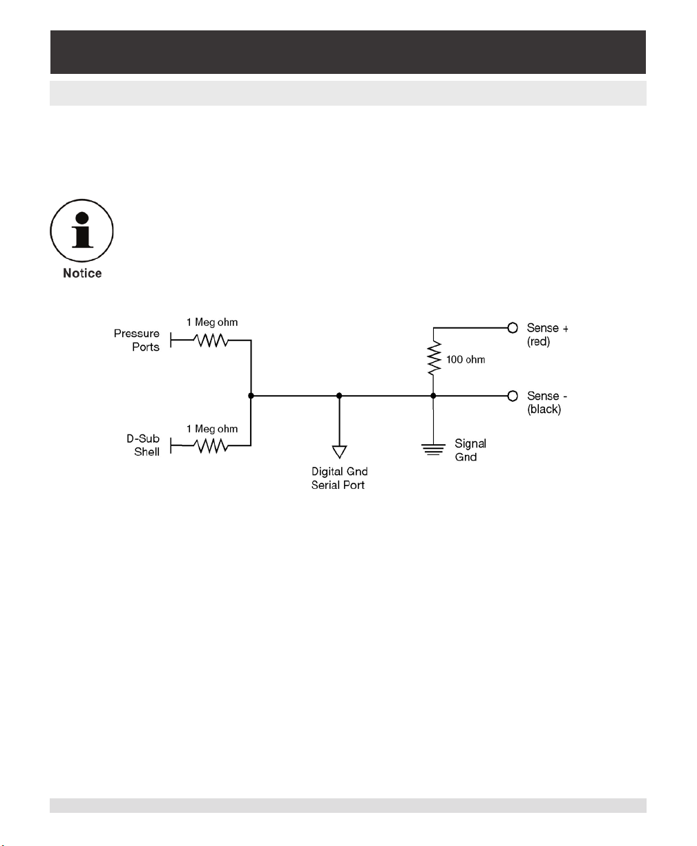
8.1.3 Connection Congurations
The diagrams shown are of typical current measurement connections. The insertion resistance is 100 ohms. The “Sense +” jack (red) is inserted on the high-side and the “Sense –”
jack (black) is inserted on the low-side in the loop.
The pressure port ttings, and the d-sub shell of the RS-232
connector are electrically common to the “Sense –” connection
each through 1 Meg ohm resistors. The RS-232 digital ground is
connected directly to the “Sense –”. The connections should be
isolated from the current loop connections.
Figure 8.1.3 - Electrical Diagram (Current Input option)
36 Operating Instructions CPG2300 Series
Page 37
Portable Digital Pressure Gauge
CPG2300 Series
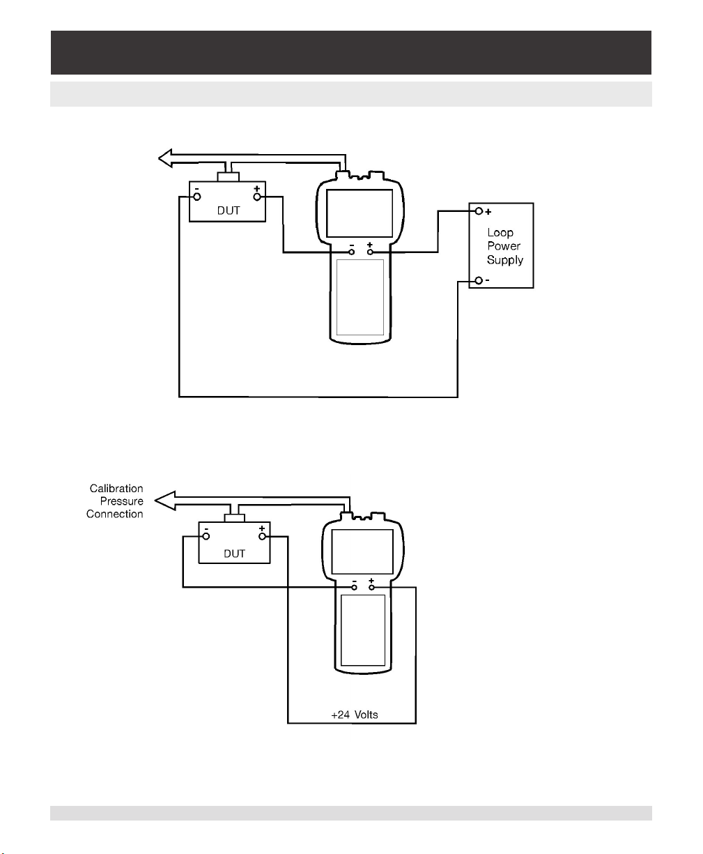
8.1.4 Application Diagrams
Figure 8.1.4a - Connections in a powered loop
Figure 8.1.4b - Connections using CPG2300 loop power
Operating Instructions CPG2300 Series 37
Page 38

Portable Digital Pressure Gauge
CPG2300 Series
Notes
38 Operating Instructions CPG2300 Series
Page 39

Portable Digital Pressure Gauge
CPG2300 Series
9. Calibration
The CPG2300 automatically adjusts the pressure readings for the eects of temperature
and non-linearity within the calibrated temperature range of 0-50°C. Thus, a calibrated
CPG2300 operated within its temperature band, and with proper zero and span settings,
will provide accurate pressure measurements.
The sensor should have the span veried periodically to insure its stability. Initially, the
recommended period between calibrations is 180 days. This period may be extended as
condence is gained in the span stability.
9.1 Environment
Whenever possible, calibrate the CPG2300 at the same ambient temperature as its
normal operating environment. The temperature should be stable and within the specied
calibration range. In addition, for maximum accuracy, see that the CPG2300 is at rest on
a stable platform which is free of vibration and shock, and oriented similar to its operating
attitude.
9.2 Equipment
Appropriate pressure and vacuum sources and calibration reference standards for the
CPG2300’s pressure range can be used. A vacuum pump capable of generating 600
mTorr absolute is recommended for calibrating zero-based absolute pressure transducers.
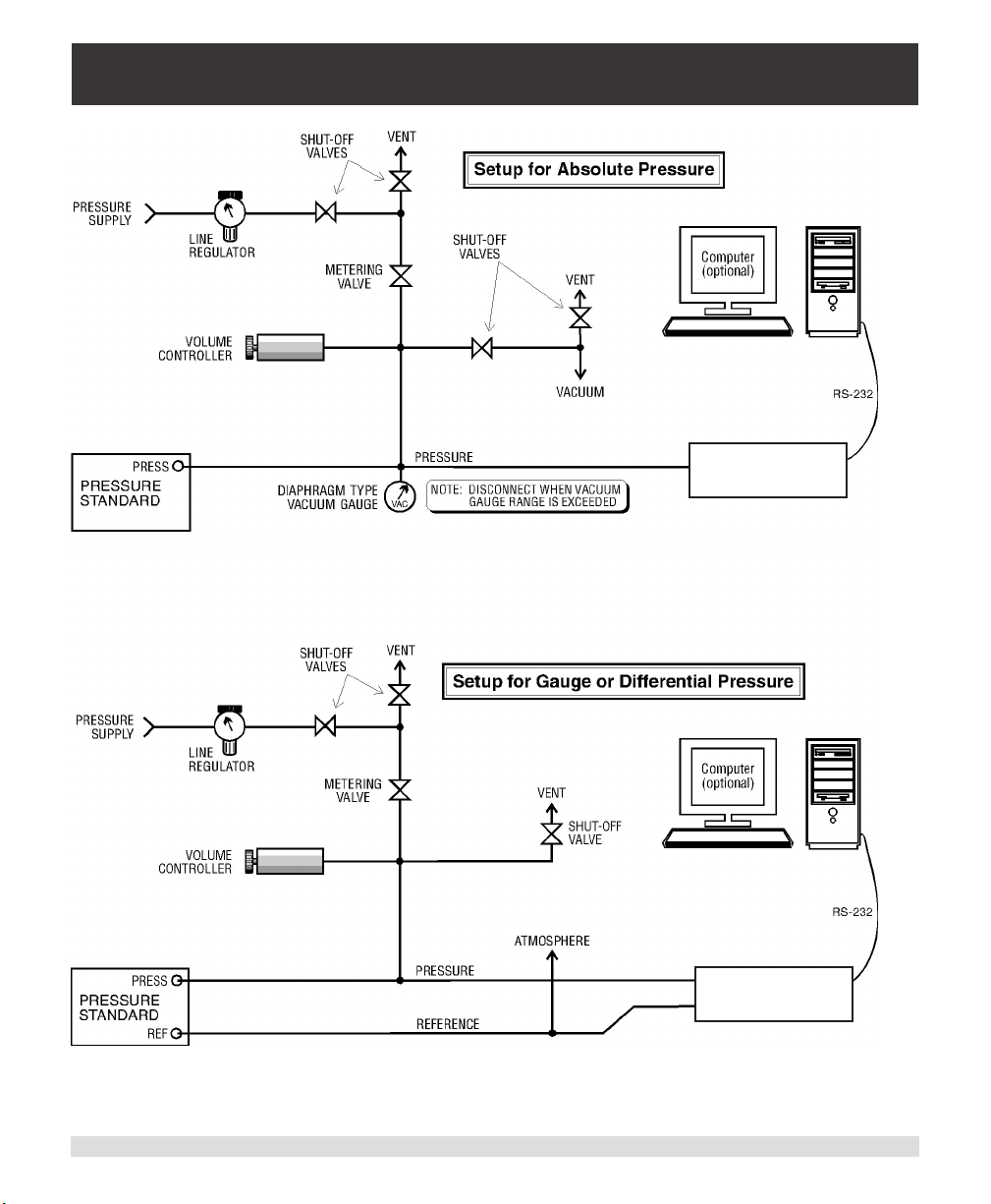
Refer to Figure 9.2 for an example of equipment setup.
Operating Instructions CPG2300 Series 39
Page 40
Portable Digital Pressure Gauge
CPG2300 Series
MODEL 2300
PRESSURE GAUGE
MODEL 2300
PRESSURE GAUGE
Figure 9.2 - Calibration Setup
40 Operating Instructions CPG2300 Series
Page 41

Portable Digital Pressure Gauge
CPG2300 Series
9.3 Pressure Standard
Mensor recommends the use of appropriately accurate primary pressure standards when
calibrating this instrument. Such standards should be sucient so that when the techniques of the ISO Guide to the Expression of Uncertainty in Measurement (GUM) are
applied, the instrument meets its accuracy statements as required by ISO 17025, or other
applicable standards. The same requirement applies to the vacuum gauge used to set the
zero oset on absolute calibrations. The recommended absolute pressure level for setting
the zero oset is ≥ 300 millitorr.
9.4 Calibration Medium
The recommended calibration medium is dry nitrogen or clean, dry instrument air, how-
ever, special techniques must be used in lling the connection lines and transducer.
9.5 Calibration Process
The calibration process described below is for local operation via the instrument keypad.
Connect the CPG2300 sensor to be calibrated as shown in Figure 9.2.
When the Calibration function is selected from the sensor setup screen, the password
entry screen will be displayed. Enter the four-digit password and then press the ◀┘ (enter)
key. For more information on entering or changing the password, see the Local Operation
section.
9.5.1 Zero Adjustment
Access the zero calibration screen as described in the Local Operation section.
For gauge sensors: Vent the CPG2300 and adjust the display to show zero pressure by
using the arrow keys on the front panel. When zero is shown, press the ◀┘ (enter) key.
For absolute sensors: Connect a vacuum source to the pressure port of the sensor to be
calibrated. Evacuate the sensor to a low pressure between 600 mTorr absolute and 20%
of the selected transducer’s span. Allow sucient time for the applied pressure to stabilize
and adjust the measured pressure on the zero calibration screen to match the true applied
pressure. Press ◀┘ (enter) key to store the zero oset.
9.5.2 Span Adjustment
Access the span calibration screen as described in the Local Operation section of this
manual.
Set a known pressure to the pressure port of the sensor to be calibrated equal to, or near,
the upper end of the range of the instrument. The applied pressure must be greater than
50% of the span or span adjustments will not be accepted. Adjust the measured pressure
on the span calibration screen to match the true applied pressure. Press the ◀┘ (enter)
key to store the span oset data.
Operating Instructions CPG2300 Series 41
Page 42

Mensor
201 Barnes Drive
San Marcos, Texas 78666
Tel: 512-396-4200
Toll Free: 800-984-4200
Fax: 512-396-1820
[email protected]
www.mensor.com
Operating Instructions CPG2300 Series PN 0017441003N • 01/2017
WIKA Alexander Wiegand SE & Co. KG
Alexander-Wiegand-Straße 30
63911 Klingenberg / Germany
Tel: (+49) 93 72/132-5015
Fax: (+49) 93 72/132-8767
[email protected]
www.wika.de
 Loading...