

Page 1
INSTRUCTION MANUAL
TEMPERATURE SWITCHES SERIE TXS, TXA
NI-492WE
Rev. 4 05/18
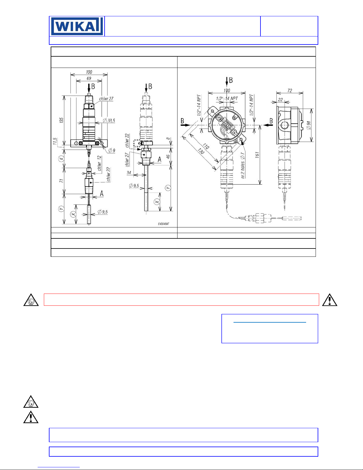
WEATHERPROOF AND INTRINSICALLY SAFE:MODELS TXS; FLAMEPROOF: MODELS TXA
CORD CABLE INSTRUMENT INSTRUMENT WITH JUNCTION BOX
Stem Type C-Q-R Stem Type B
WEIGHT 0,4kg Dimension in mm WEIGHT 1kg Dimension in mm
Stem Type B: Y = 125mm ; X = 50mm
Stem Type C: K = 2m ; Y max. = 350mm Stem Type R: K = 10m ; Y max. = 1800mm
For surface mounting use two screws M6 (not supplied with the instrument)
NOTE: dimensions and weights are not binding unless released on certified drawings.
CAUTION
Before installing, using or carrying out maintenance on the instrument it is necessary to read and understand the indications given
in the attached Instruction Manual.
The instrument must only be installed and maintained by qualified personnel in relation to working with instruments for hazardous
areas.
INSTALLATION IS TO BE CARRIED OUT ONLY AFTER CHECKING THAT INSTRUMENT CHARACTERISTICS ARE
CONSISTENT WITH PROCESS AND PLANT REQUIREMENTS.
The functional features of the instrument and its degree of protection are shown on the identification plate fixed to the case.
CONTENTS:
GENERAL
1 2 -OPERATING PRINCIPLE
3 -MODEL CODE
4 -NAMEPLATE AND MARKINGS
5 -SPECIAL CONDITIONS FOR SAFE USE (X)
6 -SET POINT ADJUSTMENT
7 -SET POINT CALIBRATION
8 -INSTRUMENT PLUMBING
9 -MOUNTING AND CONNECTIONS
10 -PUTTING INTO OPERATION
11 -VISUAL INSPECTION
12 -FUNCTIONAL VERIFICATION
13 -STOPPING AND DISMOUNTING
14 -DISPOSAL
15 -TROUBLE SHOOTING
SAFETY INSTRUCTIONS FOR USE IN EXPLOSIVE ATMOSPHERES
RECOMMENDATIONS FOR THE SAFE USE OF THE INSTRUMENT
Stem Type Q: K = 5m ; Y max. = 900mm
DOCUMENT CORRELATED
to document authenticated with certificates
N° IECEx PRE 16.0073X
N° IECEx PRE 16.0074X
All data, statements and recommendations supplied with this manual are based on information believed by us to be reliable. As the conditions of effective
use are beyond our control, our products are sold under the condition that the user himself evaluates such conditions before following our recommendations
for the purpose or use foreseen by him.
This document is the property of ALEXANDER WIEGAND SE &Co and may not be reproduced in any form, nor used for any purpose other than for which
it is supplied.
Page 2
INSTRUCTION MANUAL
range
Max working
temperature
(T max.)
Shall not exceed the
maximum
temperature specified
on the nameplate
(see fig.1 item 5).
Max electrical rating
(resistive load)
5A@24V d.c.; 5A@250V a.c.
See nameplate of the instrument
(electrical rating)
Max electrical
rating
(resistive load)
5A@24V d.c.;
5A@250V a.c.
See nameplate of
the instrument
(electrical rating)
1 - GENERAL
1.1 FOREWORD
The wrong choice of a models or a version, as well as the
incorrect installation, lead to malfunction and reduce instrument
life. Failure to follow the indications given in this manual can
cause damage to the instrument, the environment and persons.
1.2 ALLOWED OVERRANGES
Temperature exceeding the working range can be allowed only
for testing proposal up to the proof temperature. Continuous
temperature exceeding the (adjustable) “RANGE* (see fig 1) can
be applied to the instrument, provided they are clearly stated in
the instrument features (see fig.1, “MAX TEMPERATURE”).
The current and voltage values stated in the technical
specifications and data plate must not be exceeded: transitory
overranges can have a destructive effect on the switch.
1.3 TEMPERATURES
The temperature of the instrument is influenced by the
environmental and process temperature. Special attention must
be taken to avoid the exceeding of the limits specified in table 1
and 2.
For the instrument version TX**B* (stem for direct mounting) the
following table is applicable
Table 1 – Temperature conditions
Temp.
Classification
T6
T5
T4
T3
T2
T1
Ambient
temperature
range (Tamb)
-50 … +60 °C
-50 … +85 °C
For the instrument versions TX**C*, TX**Q*, TX**R* (stem for
remote mounting) and TX**S* (helical bulb for ambient
temperature) the following table is applicable
Table 2 – Temperature conditions
Temperature
Classification
T6
T5
T4
T3
T2
T1
Ambient
temperature
(Tamb)
-50..+60 °C
-50..+85 °C
2 - OPERATING PRINCIPLE
The operating principle is based on a pressure measuring
element, connected via a capillary tube to a bulb. This system is
partially filled with a volatile liquid, the residual free volume being
filled by its saturated vapour. In this system a pressure is
generated which is a non-linear function of bulb temperature; this
pressure acts on a stainless steel diaphragm which applies a
force to a stiff disc; this force is directly proportional to the
temperature value to which the bulb is submitted and is
contrasted by an compression spring charged by a suitable bush.
When the force balance point is exceeded, the stiff disc shifts
and, by means of a rigid rod, activates one or two
simultaneous release electric microswitches. The
microswitches are of the rapid release type with automatic rearm.
When the temperature moves away from the set values,
returning towards the normal values, the switch is rearmed.
3 - MODEL CODE
See Annex 1
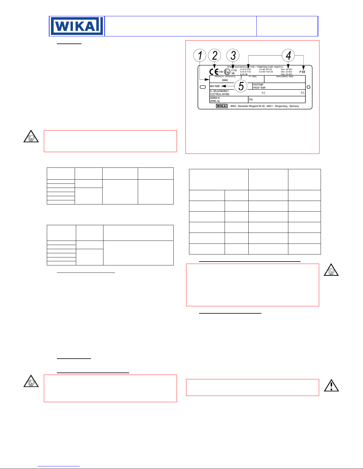
4 - NAMEPLATE AND MARKINGS
The i nstru ment is f itted wit h a metal plate beari ng al l its functional
characteristics and in case of flameproof or intrinsic safety
execution, also the markings prescribed by standard IEC/EN
60079-0. Fig.1 shows the plate mounted on flameproof
instruments.
NI-492WE
Rev.4 05/18
Fig. 1 - Flameproof instruments plate
1 Notified body that issued the type certificate and number of said
certificate.
2 CE marking and identification number of the notified body
responsible for production surveillance.
3 Apparatus classification according to ATEX 2014/34/EU
directive.
4 Type of protection and ambient temperature limits of operation.
5 Max working temperature
The following table gives the relationship between hazardous
areas, ATEX Categories and Equipment Protection Level (EPL)
listed on the flameproof instrument nameplate.
Hazardous area
Gas, vapours,
fog
Gas, vapours,
fog
Gas, vapours,
fog
Zone 0 1G Ga
Zone 1 2G or 1G Gb or Ga
Zone 2 3G, 2G or 1G Gc, Gb or Ga
Dust Zone 20 1D Da
Dust Zone 21 2D or 1D Db or Da
Dust Zone 22 3D, 2D or 1D Dc, Db or Da
5 - SPECIAL CONDITIONS FOR SAFE USE (X)
The instrument cannot be repaired (see also throubleshooting).
Should the instrument be installed without a junction box require
an electric connection suitable for the mode of protection chosen
at the free end of the cable.
Should the instrument be installed in mines (Group I) the elettrical
connection has require to be protected by chemical agents.
Therefore a mounting with cable protected by tubing is
mandatory.
6 - SET POINT ADJUSTMENT
The compression of the spring can be regulated by means of the
bush (for adjustment) in such a way that the switch is released
when the temperature reaches (either increasing or decreasing)
the desired value (set point). The instrument is usually supplied
with the switches set at 0°C or at the lowest setting range value
if this is higher than 0°C (factory calibration).
The instrument is supplied with an adhesive label showing the
set point calibration value. With factory calibration the values
are not indicated on the label as these are temporary and will be
modified with the definitive values. Prior to installation the
instrument must be calibrated and the definitive calibration
values written on the label.
If the instrument has been ordered with a specific calibration, it
is a good rule to check the calibration values marked on the
relevant adhesive label, prior to installation.
Categories
according to
2014/34/EU
Directive (ATEX)
EPL
2 of 7
Page 3
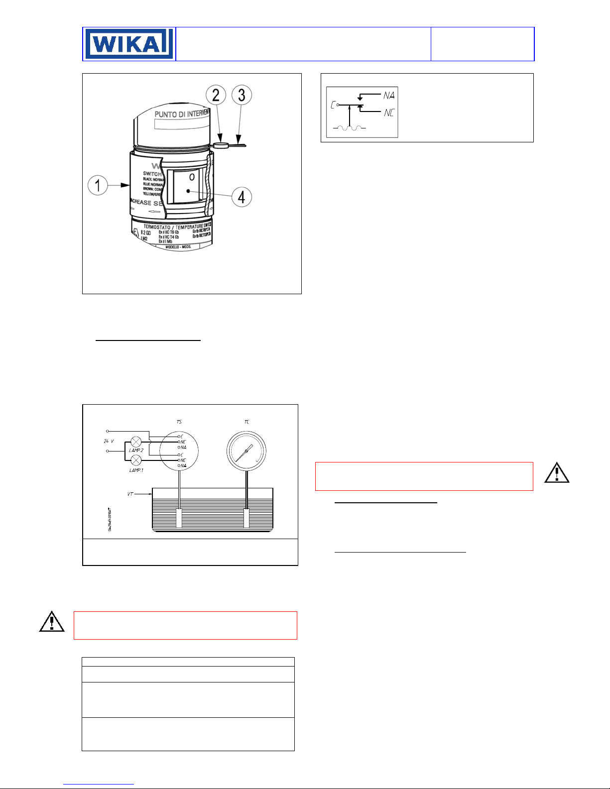
The position of the adjusting bush is given in Fig. 2.
Fig. 2 - Adjusting bush and plumbing
Adjustment slot cover
Sealing lead
Stainless steel wire
Adjusting bush
The effect of the sense of rotation of the adjusting bush is shown
on the slot cover. Rotate the bush by inserting a 3mm dia. rod or
drill into the holes on the bush itself (It recommends using a drill
bit on the side of the shank).
7 - SET POINT CALIBRATION
In order to proceed with the calibration and the periodical
functional verification of the instrument a suitable calibration
circuit (Fig. 3) and of an adequate source of heat are required.
The test instrument should have a measurement range
approximately equal to or slightly wider than the pressure switch
range and should have an accuracy consistent with the accuracy
required to calibrate the set point.
Fig. 3 – Calibration circuit
TS - Temperature switch
TT - Test thermometer
TB - Thermostatic bath
7.1 PRELIMINARY OPERATIONS
Slide up the adjustment cover (Fig. 2 item 1).
7.2 CALIBRATION CIRCUIT AND OPERATIONS
Prepare the control circuit as indicated in Fig.3
If the instrument is equipped with two contacts, remember that
they are released simultaneously but within the specification
tolerance.
The warning lamps should be connected to the terminals NA or
NC according to the required contact action.
Fig. 4 – Color of wires and function
GDN-Internal grounding connection: color jellow/green
C-Common: color brown
NO-Normally open: color blue
NC-Normally closed: color black
C-Common: color gray
NO-Normally open: color red
NC-Normally closed: color white
.
INSTRUCTION MANUAL
NI-492WE
Rev.4 05/18
Contacts status at atmospheric pressure.
C - Common
NA - Normally open
NC - Normally closed
Connection between C and NA
• If the circuit is open at the workin temperature, the instrument
closes the circuit when the set point is reached with temperature
on rise (closure on rise).
• If the circuit is closed at the working temperature, the instrument
opens the circuit when the set point is reached with temperature
on fall (opening on fall).
Connection between C and NC
• If the circuit is closed at the working temperature, the instrument
opens the circuit when the set point is reached with temperature
on rise (opening on rise).
• If the circuit is open at the working temperature, the instrument
closes the circuit when the set point is reached with temperature
on fall (closure on fall).
The temperature switch must be kept in the normal installation
position, i.e. with the temperature connection downwards.
Modify the temperature in the circuit up to the desired
microswitch set point value.
Using a 3mm dia. rod drill into the holes on the bush (It
recommends using a drill bit on the side of the shank).
Adjust its position until the relative lamp turns on (or turns off);
then turn it in the opposite direction until the lamp turns off (or
on). Slowly turn the bush again until the lamp turns on (or off)
7.3 SET POINT VERIFICATION
Increase the temperature up to the normal working temperature
(Tw), wait the stabilization of the temperature. Modify, slowly the
temperature up to the set value (Ti) and record the set point
value. Write the set point value on the adhesive label.
Note: the verification of the repeatability have to be tested
checking the set point (Ti) three times approaching the set point
from the same starting point (Tw). The temperature cycles have
to be performed slowly.
7.4 FINAL OPERATIONS
Disconnect the instrument from the calibration circuit.
Close the adjustment slot by sliding down the slot cover (Fig. 2,
1), then seal with lead the instrument.
Mount on pressure connection the protecting cap supplied with
the instrument. It should be definitively removed only during the
connection steps.
8 - INSTRUMENT PLUMBING
The plumbing (see Fig. 2), aimed as a guarantee against
possible tampering of the calibration, can be carried out using a
flexible steel wire (2), 1 mm
case in the groove purposely provided.
9 - MOUNTING AND CONNECTIONS
9.1 MOUNTING
Mount instruments with capillary either on pipe or surface by
means of the proper bracket (see Fig. 9 and 10) or direct on plant.
Select a location where possible shocks and temperature
variations remain within tolerable limits.
For the instrument with capillary the difference in height between
bulb and case have not exceeding two meters (fig 11 and 12
distance h).
9.2 INSTALLATION OF TEMPERATURE SWITCH
WITH DIFFERENCE IN HEIGHT BETWEEN BULB
AND INSTRUMENT ENCLOSURE GREATER THAN 2
METERS
Micro 1
9.2.1 TEMPERATURE SWITCHES CLASS SAMA II A
Difference in height between bulb and instrument enclosure
causes a systematic error of set point calibrated value (“bulb
elevation error”). This error can be corrected during calibration
using the table attached to our technical instruction IS-TC.401E,
available on request.
Micro 2
2
in section, wound up around the
3 of 7
Page 4

9.2.2 TEMPERATURE SWITCHES CLASS SAMA II C
Difference in height between bulb and instrument enclosure
when installed must not exceed two meters.
With a difference of two meters the set point value fixed during
the calibration may be affected by a maximum error of 1.5°C.
This error depending on the normal reference temperature, the
working temperature and the set point. For further clarification
request IS-TC.401E.
9.3 BULB AND CAPILLARY
With reference to figure 5 unscrew the fitting (3) from the seal
press (2) and slide it off from the bulb (5).
Fig. 5 – Mounting of bulb
1 - Armored capillary
2 - Stuffing nut (SW
12)
3 - Rotating fitting (SW
22)
4 - Thermowell
5 - Bulb
6 - Stainless steel
washer
7 - PTFE washer
INSTRUCTION MANUAL
NI-492WE
Rev.4 05/18
9.5 ELECTRICAL CONNECTIONS
It is recommended to carry out the electrical connections
according to the applicable standards. In case of flameproof or
intrinsic safety instruments see also the standards IEC/EN60079-14. The following mounting arrangements are possible.
9.5.1 MOUNTING WITH CORD CABLE
Run the cable so that it cannot be easily damaged (e.g. due to
too narrow bends, heat sources) and strain it.
Mount, if provided, the external ground device on the electrical
connection of the instrument.
The external ground screw is obligatory for flameproof
constructions.
This device is to be threaded on while holding the electrical
connection steady with a 27 mm wrench on hex, until it reaches
the bottom of the thread (Fig. 7).
Fig. 7 - Mounting of ground device
DO NOT TURN
Mount the fitting (3) on the thermowell (4) and tighten it using the
appropriate key. Rid the capillary from the armored by pulling the
bulb (5) with one hand while holding the stuffing nut with the other
(2).
Insert the bulb (5) into the thermowell (4) after covering it with
the paste to improve the transmission of heat.
Verify that the bulb touches the bottom.
Insert the PTFE seal with the relative stainless steel washers into
the fitting (3).
Screw the seal press (2) onto the fitting (3) taking care not to
bend the capillary and relative sheath and tighten until the PTFE
seal is tight on the capillary tube.
Run the capillary protected by the armor in the established
direction, avoiding tight bends, and block using the stainless steel
bands. If a large amount of capillary remains this should be rolled
up and fixed tightly. The coil must not have a diameter of less
than 200 mm.
9.4 TEMPERATURE SWITCHES WITH HELICAL
BULB
The temperature switch has to be installed protecting the sensing
element (bulb) against heat radiation and accidental bumps .
Fig. 6 -
Temperature switch for ambient temperature measurement
9.5.2 MOUNTING WITH CABLE PROTECTED BY
FLEXIBLE TUBING
Mount, if provided, the external ground device on the electrical
connection of the instrument. This device is to be threaded on,
while holding the electrical connection steady with a 27 mm
wrench on hex, until it reaches the bottom of the thread (fig. 8).
The external ground screw is obligatory for flameproof
constructions.
If the flexible tubing is fitted with a male thread, apply a nipple to
the electrical connection.
CAUTION: the adaptor is to be threaded on while holding the
electrical connection steady with a 27 mm wrench on hex (fig.8)
Fig. 8 - Mounting of adaptors
DO NOT TURN
9.5.3 MOUNTING WITH CABLE PROTECTED BY
METAL TUBING
CAUTION: mounting with cable protected by metal tubing is to
be carried out avoiding any torque on the electrical connection
while assembling the various fittings.
In order to make easier the instrument removal for check and
calibration it is advisable to apply on the instrument a junction
box provided with terminals.
CAUTION: accessories used for installation have to be certified
according to standards EN or IEC
4 of 7
Page 5

9.5.4 MOUNTING INSTRUMENT WITH JUNCTION BOX
Versions with junction box have three cable entries, a terminal
block with three/six terminals, a terminals identification plate, an
internal and external grounding connections.
The terminals are identified as follows:
Identification No. Function Micro No.
1 Common
2 Normally Open
3 Normally Closed
4 Common
5 Normally Open
6 Normally Closed
Mounting with cable protected in metal tube is to be carried out
so as to prevent possible condensate from entering the junction
box.
The junction box is to be surface mounted using the bracket
suppiled with it.
Warning: Instruments with aluminium enclosure. The
instrument must be protected against accidental impacts of the
housing.
The instrument is supplied with two protective earthing
connections, one inside and one outside the enclosure.
The connection provide effective connection of a conductor with
a cross-sectional area of at least 4 mm2
CAUTION: fittings used for the electrical connection of the
flameproof instruments shall be certified according the IEC or EN
standards and shall guarantee instrument degree of protection
(IP66)
CAUTION: cable entries not used must be plugged and sealed
with the plugs provided so as to prevent raining water or other
from entering the junction box. In case of flameproof
instruments these plugs, if not correctly mounted and
blocked to prevent their removal, do NOT guarantee the
mode of protection Ex-d. Furthermore, in order to guarantee
the degree of protection IP65 and the non-loosening of Conduit
Seal or packing gland, it is prescribed to seal the threads of
connection with the same anaerobic sealant used for the plugs.
For instance, a sealant like Loctite ® 648 can be applied on the
thread of plugs, Conduit Seal or packing gland before screwing
them on the box.
9.6 WIRING
The multicore cable used for electric wiring has a 7 mm OD
silicone sheat for one contact versions, 8 mm OD for two contact
versions. Each wire has a section of 0,5 mm
silicone insulated. Wires ends are factory tinned. The colour of
insulator defines the contact function (see Fig. 4 and stampings
on slot cover).
Before starting wiring, check that electric lines are not
powered.
The instrument is to be grounded according to applicable
electrical codes. Make use of the internal yellow-green wire
and, if the cable is not protected by metal tubing, connect the
external screw of the groundig device supplied with the
instrument.
Should the instrument be fitted with junction box, make sure that
no deposits or wire ends remain inside the box. Tightening and
blocking the cover as the wiring of the junction box is finish.
Warning: The intrinsic safety instrument may be equipped with
micro switches SPDT or DPDT. All the electrical connection must
be part of intrinsically safe circuits. The entry parameters relevant
for intrinsic safety are listed on the nameplate of the instrument.
1
2
2
(20 AWG) and is
INSTRUCTION MANUAL
NI-492WE
Rev.4 05/18
10 - PUTTING INTO OPERATION
The instrument starts operating as soon as is energized.
11 - VISUAL INSPECTION
Periodically check the external condition of the enclosure.
In case of flameproof or intrinsic safety instruments, inspections
of the electrical installation are to be carried out also according
to customer procedures and at least in accordance with Standard
IEC/EN-60079-17.
The flameproof and the intrinsic safety instruments, installed in
explosive atmospheres for the combustible dust presence, must
be periodically cleaned up externally in order to avoid dust
accumulating.
12 - FUNCTIONAL VERIFICATION
This will be carried out according to the Customer’s control
procedures and as minimum yearly if used as an alarm of max
temperature.
The instruments can be verified on the plant if installed as
illustrated in Fig. 11,12 and 13.
To avoid any risk it is recommended check the set point on site
without open the cover of the junction box, without dismount the
cable gland, without unplugging the power cable.
The flameproof or intrinsic safety instruments may be checked
on site only if apparatus suitable for explosive atmosphere are
used.
If this is not the case it is necessary remove the instrument from
the plant and carry out the verification in a testing room.
If the verification of the set point is performed unplugging the
power cable from the terminal block it is recommended power off
the instrument to avoid any electrical hazard
WARNING: Instrument models TXA, flameproof.
Before open the cover of the junction box or the cable gland
check the absence of explosive atmosphere and check that the
instrument is de energized
Verification consists in check the calibration value and possibly
regulating the adjustment bush (see §6) that is separate from the
electrical compartment.
13 - STOPPING AND DISMOUNTING
Before starting the following operations, ensure that plant and
equipment have been put in conditions allowing to carry out
them safely
Remove the power supply (signal) from the electrical line.
With reference to Fig 5,11 and 12.
Loosen and remove the seal press being careful not to bend the
capillary and protective sheath (Fig.4).
Warning: Do not touch the bulb and the parts in contact with the
thermowell if hot.
Loosen and remove the fitting (3) then extract the bulb (5) from
the thermowell (4) holding it by the capillary tube (1), without
bending it.
WARNING: Instrument series TXA, flameproof.
Before open the cover or the cable gland of the junction box
check the absence of explosive atmosphere and check that the
instrument is de energized.
Unscrew the swivel (3) (electric cable tubing).
Remove cover from junction box and disconnect wires from
terminals and grounding screws.
Remove the screws fixing the box to the panel (or pipe) and
remove the instrument taking care to slide electric conductors out
from the case
Mount the cover of the junction box. Insulate and protect cables
around, if any. Temporarily plug the thermowell
In case of flameproof or intrinsic safety instruments, it is
recommended to follow, at least, the standard IEC/EN-60079-17
for the withdrawal from service of electrical apparatus.
14 - DISPOSAL
The instruments are mainly made of stainless steel and
aluminium and therefore, once the electrical parts have been
dismounted and the parts coming into contact with fluids which
could be harmful to people or to environment have been properly
dealt with, they can be scrapped.
5 of 7
Page 6

INSTRUCTION MANUAL
NI-492WE
Rev.4 05/18
15 - TROUBLE SHOOTING
IMPORTANT NOTE: operations involving replacement of essential components must be carried out at our workshop, especially
for instruments with flameproof certificate; this is to guarantee the user the total and correct restoration of the product original
characteristics.
MALFUNCTION PROBABLE CAUSE REMEDY
Set point shift
Slow response
No actuation
Undue actuation
Fig. 9 – Bracket for wall mounting Fig. 10 - Bracket for 2 pipe”
Deposits on thermowell or bulb
Filling fluid leakage
Deposits on thermowell or bulb Check and clean surfaces
Loosened electrical joints
Interrupted or short-circuited electrical line
Microswitch contacts damaged
Filling fluid leakage
Accidental shocks
Interrupted or short-circuited electrical line
Check and clean surfaces
Replace the instrument
Check all electrical joints
Check the conditions of the electrical line
Replace the instrument
Replace the instrument
Modify the mounting
Check the conditions of the electrical line
Fig. 11 - Surface or 2” pipe mounting Fig. 12 - Surface mounting with Junction Box
1) Temperature switch 5) Branch Connection Fittings 9) Fitting 13) Conduit Seal
2) Capillary 6) Process line 10) Swivel adapter or cable gland 14) Junction box
3) Thermowell 7) Mounting bracket 11) Junction Box (see fig 12)
4) Bulb 8) 2” pipe / Surface 12) Stem (see fig 12)
6 di 7
Page 7

A
Fig. 13 – Mounting with cord cable Fig. 14 – Mounting in a junction box
INSTRUCTION MANUAL
NI-492WE
Rev.4 05/18
Fig. 15 - Thermowell: examples of installation
Annex 1 – Model code
MODEL CODE
1
1.1
Ignition protection mode
Enclosure code (material)
1.2
Sensor code
1.3
Electric Contacts
Options
2
TX
Example: Intrinsic Safety execution
S
A
2
4
For further information
see datasheet
B
C
Q
R
S
E
L
M
Weatherproof
Ex d
Aluminium
316 s.s.
Direct Mounting
Remote mounting with 2m di capillary
Remote mounting with 5m di capillary
Remote mounting with 10m di capillary
Helical bulb
Silver SPDT
Silver DPDT
Gold DPDT
WIKA Alexander Wiegand SE & Co. KG
lexander-Wiegand-Straße 30
63911 Klingenberg • Germany
Tel. +49 9372 132-0
Fax +49 9372 132-406
info@wika.de
www.wika.de
12/2018 WIKA based on 05/2018 CELLA
 Loading...