

Page 1
INSTRUCTION MANUAL
NI-492E
REV. 0 01/05
TEMPERATURE SWITCHES SERIES TXS,TXN,TXA
WEATHERPROOF (Series TXS) AND FLAMEPROOF (Series TXA, TXN)
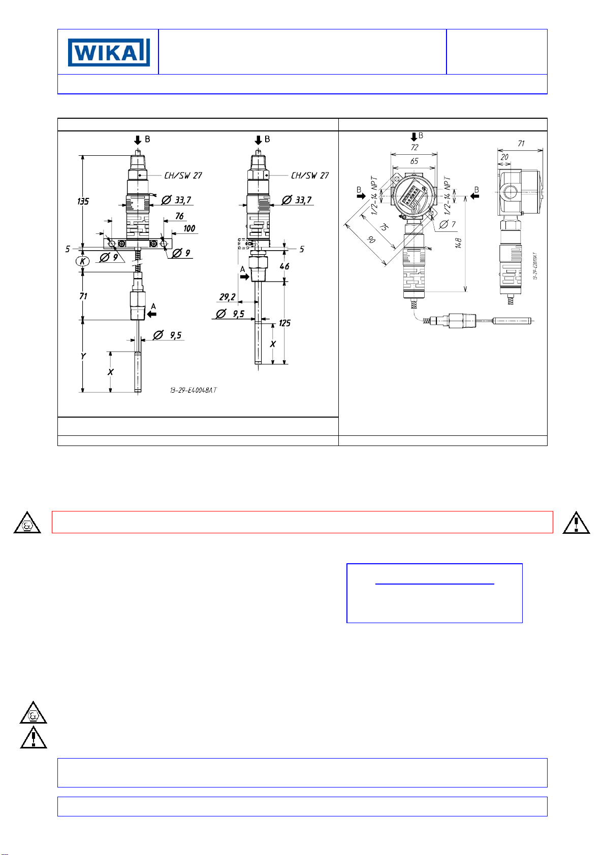
INSTRUMENT STANDARD INSTRUMENT WITH JUNCTION BOX
Stems Type C-Q-R Stem Type B
Stem Type B: Y =125mm ; X = 50mm Stem Type Q: K = 5m ; Y max.=900mm
Stem Type C: K = 2m ; Y max.=350mm Stem Type R: K = 10m ;Y max.=1800mm
WEIGHT 0,4kg Dimensions in mm WEIGHT 1kg Dimensions in mm
NOTE: dimensions and weights are not binding unless released on certified drawings.
CAUTION
• Before installing, using or carrying out maintenance on the instrument it is necessary to read and understand the indications given
in the attached Instruction Manual.
• The instrument must only be installed and maintained by qualified personnel.
• INSTALLATION IS TO BE CARRIED OUT ONLY AFTER CHECKING THAT INSTRUMENT CHARACTERISTICS ARE
CONSISTENT WITH PROCESS AND PLANT REQUIREMENTS.
• The functional features of the instrument and its degree of protection are shown on the identification plate fixed to the case.
CONTENTS:
1 - GENERAL
2 - OPERATING PRINCIPLE
3 - IDENTIFICATION PLATE AND MARKINGS
4 - SPECIAL CONDITIONS FOR SAFETY USE (X)
5 - SET POINT ADJUSTMENT
6 - SET POINT CALIBRATION
7 - INSTRUMENT PLUMBING
8 - MOUNTING AND CONNECTIONS
9 - PUTTING INTO OPERATION
10 - FUNCTIONAL VERIFICATION
11 - TROUBLE SHOOTING
12 - STOPPING AND DISMOUNTING
13 - DEMOLITION
14 - NOTE FOR INSTALLATION
SAFETY INSTRUCTIONS FOR USE IN EXPLOSIVE ATMOSPHERES
RECOMMENDATIONS FOR THE SAFE USE OF THE INSTRUMENT
DOCUMENT CORRELATED
to document authenticated with certificates
N° CESI 05 ATEX 002X
N° CESI 05 ATEX 003
All data, statements and recommendations supplied with this manual are based on information believed by us to be reliable. As the
conditions of effective use are beyond our control, our products are sold under the condition that the user himself evaluates such
conditions before following our recommendations for the purpose or use foreseen by him.
The present document is the property of ETTORE CELLA SPA and may not be reproduced in any form, nor used for any purpose
other than for which it is supplied.
Page 2
INSTRUCTION MANUAL
1 - GENERAL
1.1
FOREWORD
The wrong choice of a series or a model, as well as the incorrect
installation, lead to malfunction and reduce instrument life.
Failure to follow the indications given in this manual can cause
damage to the instrument, the environment and persons.
1.2 ALLOWED OVERRANGES
Temperatures exceeding the working range can be occasionally
tolerated provided they remain within the limits stated for the
instrument (proof temperature). Continuous temperatures
exceeding the working range can be applied to the instrument,
provided they are clearly stated in the instrument features.
The current and voltage values stated in the technical
specifications and data plate must not be exceeded: transitory
overranges can have a destructive effect on the switch.
1.3 TEMPERATURES
Due to the temperature of both the environment and the process
fluid, the temperature of the instrument could exceed the allowed
limits (normally from -40°C to +85°C). Therefore, in case it does,
suitable measures (protection against heat radiation, fluid
separators, cooling coils, heated lockers), aimed at limiting the
value, must be taken.
2 - OPERATING PRINCIPLE
The operating principle is based on a pressure measuring
element connected via a capillary tubing with a temperature
sensitive bulb. The system is partially filled with a volatile liquid
generating a pressure that is a non linear function of the bulb
temperature; this pressure is applied to a diaphragm acting on a
stiff disc with a force directly proportional to the bulb temperature.
The force is contrasted by an helical spring loaded by a suitable
bush. When the force balance point is exceeded, the stiff disc
shifts and, by means of a rigid rod, actuates one or two
simultaneous release electric microswitches. The
microswitches are of the snap acting type with automatic reset.
When the pressure moves away from the set values, returning
towards the normal values, the switch is reset.
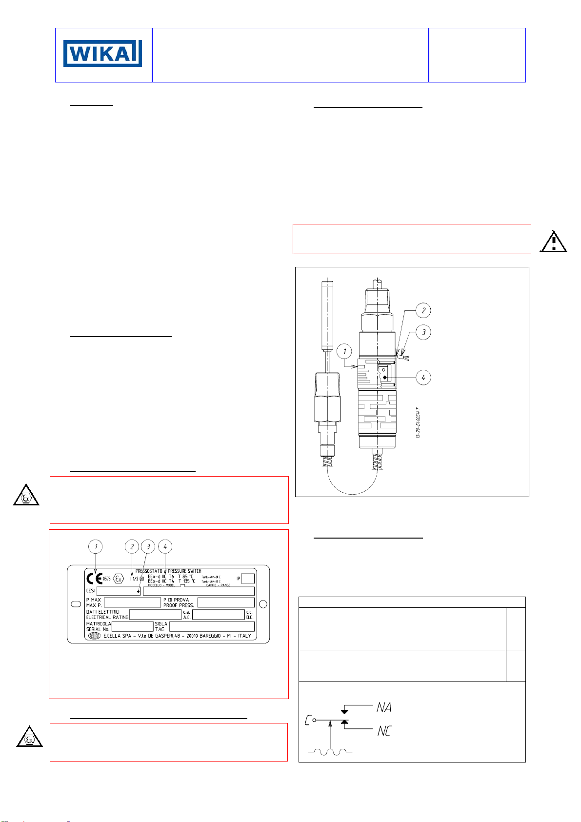
3 - NAMEPLATE AND MARKINGS
The instrument is fitted with a metal plate bearing all its functional
characteristics and – in case of explosionproof execution (Series
TXA and TXN) – also the markings prescribed by standard EN
50014 and EN 50281-1-1. Fig. 1 shows the nameplate mounted
on explosionproof instruments.
Fig. 1 - Nameplate, explosionproof instruments
1 CE marking and identification number of the notified body
responsible for production surveillance.
2 Apparatus classification according to ATEX 94/9 CE directive.
3 Notified body that issued the type certificate and number of said
certificate.
4 Mode of protection and operating ambient temperature limits.
4 - SPECIAL CONDITIONS FOR SAFE USE (X)
Explosionproof instruments (Series TXA and TXN) installed
without a junction box require an electric connection, suitable for
the mode of protection choosen, at the free end of the cable (see
Point 8).
NI-492E
REV. 5 11/02
5 - SET POINT ADJUSTMENT
The load of the helical spring can be adjusted by means of the
bush in such a way that the switch is released when the
temperature reaches (either increasing or decreasing) the desired
value (set point). The instrument is usually supplied with the
switches set at 0°C, or at the initial range value if this is above
0°C (factory calibration). The instrument is supplied with an
adhesive label showing the set point calibration value. With
factory calibration the values are not indicated on the label as
these are temporary and will be modified with the definitive
values. Prior to installation the instrument must be calibrated
and the definitive calibration values written on the label using a
suitable indelible ink pen.
If the instrument has been ordered with a specific calibration, it
is a good rule to check the calibration values marked on the
relevant adhesive label, prior to installation.
The position of the adjusting bush is given in Fig. 2.
Fig. 2 - Adjusting bush and plumbing
c Adjustment slot
cover
d Stainless steel
wire
e Sealing lead
f Adjusting bush
The effect of the sense of rotation of the adjusting bush is shown
on the slot cover. Rotate the bush by inserting a 3mm dia. rod or
drill into the holes on the bush itself.
6 - SET POINT CALIBRATION
In order to proceed with the calibration and the periodical
functional verification of the instrument a suitable calibration
circuit (Fig. 4) and an adequate temperature source are
required.
Wiring is to be carried out as shown in Fig. 3 and on the slot
cover.
Fig. 3 - Electric wiring
GDN - Ground internal : leadwire yellow/green
C - Common : leadwire brown
NA - Normally open : leadwire blue
NC - Normally closed : leadwire black
C - Common : leadwire grey
NA - Normally open : leadwire red
NC - Normally closed : leadwire white
Microswitch internal wiring. Contacts status with bulb at initial
range value.
Micro 1
Micro 2
C - Common
NA - Normally open
NC - Normally closed
Page 3

INSTRUCTION MANUAL
6.1 PRELIMINARY OPERATIONS
Slide up the adjustment cover (Fig. 2, 1).
6.2 CALIBRATION CIRCUIT AND OPERATIONS
Prepare the control circuit as indicated in Fig.4.
The warning lamps should be connected to the terminals NA or
NC according to the required contact action.
Circuit C/NA
• This circuit closes with temperature on rise and opens with
temperature on fall when temperature reaches the set point.
Circuit C/NC
• This circuit opens with temperature on rise and closes with
temperature on fall when temperature reaches the set point.
The test instrument should have a measurement range
approximately equal to or slightly wider than the temperature
switch range and should have an accuracy consistent with the
precision required to calibrate the set point.
The temperature switch must be mounted in its normal
installation position, i.e. with the stem or capillary downwards.
Adjustments
Modify the temperature in the circuit up to the desired
microswitch set point value.
Turn the adjusting bush using the adjustment rod until the relative
lamp turns on (or turns off); then turn it in the opposite direction
until the lamp turns off (or on). Slowly turn the bush again until
the lamp turns on (or off).
If the instrument is equipped with two contacts, remember that
they are released simultaneously but within the specification
tolerance.
Fig. 4 - Calibration circuit
NI-492E
Rev. 0 01/05
8.2 BULB AND CAPILLARY
With reference to Fig. 5, unscrew union (3) from stuffing gland
(2) and slide it out from bulb (5).
Mount union (3) on thermowell (4) and tighten it with a proper
wrench. Spread on bulb (5) the special paste for better heat
transmission and insert it into thermowell (4).
Be sure that bulb reaches thermowell bottom. Insert into union
(3) PTFE washer (7) with relevant st. st. washers (4). Screw
stuffing gland (2) into union (3) taking care not to twist capillary
and its armor, then tighten it until PTFE washer presses against
capillary.
Fig. 5 - Bulb mounting
TS - Temperature switch
TC - Test thermometer
VT - Thermostatic bath
6.3 FINAL OPERATIONS
Disconnect the instrument from the calibration circuit.
Close the adjustment slot by sliding down the slot cover (Fig. 2,
1), then seal with lead the instrument.
7 - INSTRUMENT PLUMBING
The plumbing (see Fig. 2), aimed as a guarantee against possible
tampering of the calibration, can be carried out using a flexible
steel wire (2), 1 mm
groove purposely provided.
2
in section, wound up around the case in the
8 - MOUNTING AND CONNECTIONS
8.1
NOUNTING
Mount instruments with capillary either on pipe or surface by
means of the proper bracket (see Fig. 8 and 9).
Select a location where possible shocks and temperature
variations remain within tolerable limits.
CAUTION: for instruments with capillary, the difference in height
between bulb and case is not to exceed two meters. If it does,
adjust set point temperature value according to the table given in
instruction IS-TC.401E.
For bracket mounting, see NI-292E.
1) Armored capillary
2) Stuffing gland (SW 12)
3) Union
4) Thermowell
Run armored capillary avoiding too narrow bends, then staple it.
Excess capillary, if any, is to be rolled up around a 200 mm dia.
min., then firmly secured.
5) Bulb
6) St. st. washer
7) PTFE washer
8.3 ELECTRICAL CONNECTIONS
It is recommended to carry out the electrical connections
according to the applicable standards. In case of explosionproof
instruments (Series TXA) see also the Standards EN-60079-14
and EN-50281-1-2 .
The following mounting arrangements are possible.
8.3.1 MOUNTING WITH CABLE LOOSE (Fig. 10)
Run the cable so that it cannot be easily damaged (e.g. due to
too narrow bends, heat sources) and strain it.
Mount, if provided, the external ground device on the electrical
connection of the instrument. This device is to be threaded on,
while holding the electrical connection steady with a 27 mm
wrench on hex, until it reaches the bottom of the thread (Fig. 6).
The external ground screw is obligatory for explosionproof
constructions.
Page 4

INSTRUCTION MANUAL
Fig. 6 - Mounting of ground device
8.3.2 MOUNTING WITH CABLE PROTECTED BY FLEXIBLE
TUBING
Mount, if provided, the external ground device on the electrical
connection of the instrument. This device is to be threaded on,
while holding the electrical connection steady with a 27 mm
wrench on hex, until it reaches the bottom of the thread (Fig. 6).
The external ground screw is obligatory for explosionproof
constructions.
If the flexible tubing is fitted with a male thread, apply a sleeve to
the electrical connection.
CAUTION: the sleeve is to be threaded on while holding the
electrical connection steady with a 27 mm wrench on hex (Fig.7)
.
Fig. 7 - Mounting of adaptors
DO NOT TURN
NI-492E
Rev. 0 01/05
Terminals are identified as follows:
Identification No. Function Micro No.
1 Common
2 Normally Open
3 Normally Closed
4 Common
5 Normally Open
6 Normally Closed
Mounting with cable protected is to be carried out so as to
prevent possibile condensate from entering the junction box
The junction box is to be surface mounted using the bracket
suppiled with it.
CAUTION: accessories used for installation have to be certified
according to standards EN 50014, 50018, EN 50281-1-1 and
guarantee the degree of protection of the instrument (IP65).
CAUTION: cable entries not used must be plugged and sealed
with the plugs provided so as to prevent raining water or other
from entering the junction box. In case of explosionproof
instruments these plugs, if not correctly mounted and
blocked to prevent their removal, do NOT guarantee the
mode of protection EEx-d. Furthermore, in order to guarantee
the degree of protection IP65 and the non-loosening of blocking
joint or packing gland, it is prescribed to seal the threads of
connection with the same anaerobic sealant used for the plugs.
For instance, a sealant like Loctite ® 648 can be applied on the
thread of plugs, blocking joint or packing gland before screwing
them on the box.
1
2
DO NOT TURN
8.3.3 MOUNTING WITH CABLE PROTECTED BY METAL
TUBING
CAUTION: mounting with cable protected by metal tubing is to be
carried out avoiding any torque on the electrical connection while
assembling the various fittings (Fig. 7).
In order to make the instrument removal easier for check and
calibration it is advisable to apply the instrument a junction box
provided with terminals.
CAUTION: accessories used for installation have to be certified
according to standards EN 50014, 50018, EN 50281-1-1 and
guarantee the degree of protection of the instrument (IP65).
8.3.4 MOUNTING WITH INSTRUMENT FITTED WITH
JUNCTION BOX
Models fitted with junction box feature three cable entries, threeor six-terminals block with terminals identification plate, internal
and external grounding connections.
8.4 WIRING
The cable used for electric wirIng has a 7 mm OD silicone sheat
for one contact models, 8 mm OD for two contact models. Each
wire has a section of 0,5 mm
Wires ends are factory tinned. The colour of insulator defines the
contact function (see Fig. 3 and stampings on slot cover).
Before starting wiring, check that electric lines are not
powered.
The instrument is to be grounded according to applicable
electrical codes. Make use of the internal yellow-green wire and,
if the cable is not protected by metal tubing, connect the external
screw of the groundig device supplied with the instrument.
Should the instrument be fitted with junction box, make sure that
no deposits or wire ends remain inside the box. The wiring
completed, put the cover on and tighten it.
2
(20 AWG) and is silicone insulated.
8.5 SPECIAL NOTE FOR THE INSTALLATION OF
TEMPERATURE SWITCHES CATEGORY 3GD, MODE OF
PROTECTION EEx - nC
Explosionproof instruments Series TXN are to be installed using
electric accessories prescribed for this execution. For instance,
junction boxes are to be suitable for mode of protection n. Apply
to standards EN-50021 for any construction detail and to EN60079-14, EN-50281-1-2 for installation.
Page 5

INSTRUCTION MANUAL
9 - PUTTING INTO OPERATION
As the signal transmitted by the instrument is used in a complex
system, it is necessary that the means of putting it into operation
are established by those in charge of the plant.
The instrument starts operating as soon as it is powered.
In case of explosionproof instruments (Series TXA and TXN),
initial inspections are to be carried out according to customer
procedures and at least in accordance with Standards EN-6007917 and EN-50281-1-2.
Otherwise it is necessary to stop them working, remove them and
carry out checks in a test room.
The verification consists in checking the calibration value and
adjusting it if required (see §5).
In case of explosionproof instruments (Series TXA and TXN)
inspections of the electrical installation are to be carried out also
according to customer procedures and at least in accordance
with Standards EN-60079-17, EN-50281-1-1.
NI-492E
Rev. 0 01/05
10 - FUNCTIONAL VERIFICATION
It will be carried out according to customer control procedures.
Explosionproof instruments (Series TXA, TXN) installed in
hazardous areas due to the presence of inflammable dusts
should be periodically cleaned externally to avoid dust
accumulation.
Instruments Series TXS may be checked on site if installation has
been made according to Fig. 9 to 12.
Instruments Series TXA, TXN may be checked on site but if
testing equipments are suitable for the environment and electric
supply is off.
11 - TROUBLE SHOOTING
IMPORTANT NOTE: operations involving replacement of essential components must be carried out at our workshop, especially
for instruments with explosionproof certificate; this is to guarantee the user the total and correct restoration of the product
original characteristics.
MALFUNCTION PROBABLE CAUSE REMEDY
Set point shift
Slow response
No actuation
Undue actuation
Deposits on thermowell or bulb
Filling fluid leakage
Deposits on thermowell or bulb Check and clean surfaces
Loosened electrical joints
Interrupted or short-circuited electrical line
Microswitch contacts damaged
Filling fluid leakage
Accidental shocks
Interrupted or short-circuited electrical line
12 - STOPPING AND DISMOUNTING
Before starting the following operations, ensure that plant and
equipments have been put in conditions allowing to carry out
them safely.
Remove the power supply (signal) from the electric line.
With reference to Fig. 5.
Loosen stuffing gland (2) taking care not to twist capillary and its
armor.
Loosen and slide out union (3), then exctract bulb from
thermowell holding the capillary, without twisting it.
With reference to Fig. 9.
Unscrew the electrical three-piece joint. Remove junction box
cover and disconnect electric wires from terminals and ground
screws.
Unscrew fixing screws of junction box and remove instrument
sliding out the electric wires.
Replace the junction box cover, insulate and protect loose
leadwires. Temporarily plug the thermowell. In case of
explosionproof instruments (Series TXA, TXN) it is recommended
to follow - at least – the Standards EN-60079-17 and EN-502811-2 for the withdrawal from service of electrical apparatus.
Check and clean surfaces
Replace the instrument
Check all electrical joints
Check the conditions of the electrical line
Replace the instrument
Replace the instrument
Modify the mounting
Check the conditions of the electrical line
13 - DEMOLITION
The instruments are mainly made of stainless steel and
aluminium; therefore, once the electrical parts have been
dismounted and the parts coming into contact with fluids which
could be harmful to people or to environment have been properly
dealt with, they can be scrapped.
14 - NOTES FOR INSTALLATION
14.1
TEMPERATURE SWITCHES CLASS SAMA II A
A difference in height between bulb and case exceeding two
meters causes a systematic error in the set point calibrated value
(“bulb elevation error”).
This error can be corrected during calibration by either increasing
or decreasing the set point value by a constant depending on the
difference in height foreseen for the installation. The “bulb
elevation error” can be corrected using the table attached to our
technical instruction IS-TC.401E, available on request.
14.2 TEMPERATURE SWITCHES CLASS SAMA II C
The temperature switch must be installed with a difference in
height between bulb and case not exceeding two meters.
With a difference of approximately two meters the set point value
fixed during calibration may be affected by an error depending on
the normal reference temperature, the working temperature and
the set point temperature. In the worst operating conditions the
set point temperature value fixed during calibration may be
affected by a maximum error of 1,5°C. For further clarification
request IS-TC.401E.
Page 6

INSTRUCTION MANUAL
Fig. 8 - Examples of mounting Fig. 9 - Mounting with junction box
NI-492E
Rev. 0 01/05
1) Temperature switch Series TX 5) Coupling 9) Sleeve 13) Blocking joint
2) Capillary tubing 6) Process line 10) Three-piece joint 14) Junction box
3) Thermowell 7) Mounting bracket 11) Box
4) Bulb 8) 2” pipe / Surface 12) Extension
Fig. 10 - Mounting with cable loose Fig. 11 - Thermowells: examples of installation
Mounting on elbow - Minimum pipe size is to be 3", if less,
provide a pipe enlargement up to 3".
Mounting on straight pipe – Minimum pipe size 3”, if less
provide a pipe enlargement up to 6".
Fig. 12 - Mounting directly on box
ETTORE CELLA SPA Viale de Gasperi, 48 - Casella Postale (P.O. Box) 58 - I 20010 Bareggio (MILANO) ITALY
Telefoni +39 029036.1146/1237/1241 - FAX +39 029036.1331 E-MAIL: CELLA@ECELLASPA.COM
 Loading...