

Page 1
Operating instructions
Betriebsanleitung
Mode d'emploi
Manual de instrucciones
Thermowell for sanitary applications, model TW61
Schutzrohr für die sterile Verfahrenstechnik, Typ TW61
Doigt de gant pour applications sanitaires, type TW61
Vaina para procesos estériles, modelo TW61
GB
D
F
E
Thermowells model TW61
Page 2

GB
Operating instructions model TW61
D
Betriebsanleitung Typ TW61
F
Mode d'emploi type TW61
E
Manual de instrucciones modelo TW61
Page 3 - 18
Seite 19 - 34
Page 35 - 50
Página 51 - 65
© 2012 WIKA Alexander Wiegand SE & Co. KG
All rights reserved. / Alle Rechte vorbehalten.
WIKA® is a registered trademark in various countries.
WIKA® ist eine geschützte Marke in verschiedenen Ländern.
Prior to starting any work, read the operating instructions!
Keep for later use!
Vor Beginn aller Arbeiten Betriebsanleitung lesen!
Zum späteren Gebrauch aufbewahren!
Lire le mode d‘emploi avant de commencer toute opération !
A conserver pour une utilisation ultérieure !
¡Leer el manual de instrucciones antes de comenzar cualquier trabajo!
¡Guardar el manual para una eventual consulta!
2
WIKA operating instructions thermowell, model TW61
11593963.03 03/2014 GB/D/F/E
Page 3

Contents
Contents
1. General information 4
2. Safety 5
3. Specications 7
4. Design and function 7
5. Transport, packaging and storage 12
6. Commissioning, operation 12
GB
Maintenance and cleaning
7.
8. Faults 14
9. Dismounting, return and disposal 15
Appendix 1: TÜV certicate 16
Appendix 2: EC declaration of conformity 18
Declarations of conformity can be found online at www.wika.com.
13
11593963.03 03/2014 GB/D/F/E
WIKA operating instructions thermowell, model TW61
3
Page 4
1. General information
1. General information
■
The thermowells described in these operating instructions have been designed and
manufactured using state-of-the-art technology. All components are subject to stringent
GB
quality and environmental criteria during production. Our management systems are certied to
ISO 9001 and ISO 14001.
■
These operating instructions contain important information on handling the thermowell.
Working safely requires that all safety instructions and work instructions are observed.
■
Observe the relevant local accident prevention regulations and general safety regulations for
the thermowell‘s range of use.
■
The operating instructions are part of the product and must be kept in the immediate vicinity of
the thermowell and readily accessible to skilled personnel at any time.
■
Skilled personnel must have carefully read and understood the operating instructions prior to
beginning any work.
■
The manufacturer's liability is void in the case of any damage caused by using the product
contrary to its intended use, non-compliance with these operating instructions, assignment of
insuciently qualied skilled personnel or unauthorised modications to the thermowell.
■
The general terms and conditions contained in the sales documentation shall apply.
■
Subject to technical modications.
■
Further information:
- Internet address: www.wika.de / www.wika.com
- Relevant data sheet:
- Application consultant:
TW 95.61
Tel.: +49 9372 132-0
Fax: +49 9372 132-406
info@wika.com
Explanation of symbols
WARNING!
... indicates a potentially dangerous situation that can result in serious injury or death,
if not avoided.
CAUTION!
... indicates a potentially dangerous situation that can result in light injuries or damage
to equipment or the environment, if not avoided.
Information
… points out useful tips, recommendations and information for ecient and trouble-
free operation.
4
11593963.03 03/2014 GB/D/F/E
WIKA operating instructions thermowell, model TW61
Page 5
1. General information / 2. Safety
DANGER!
... identies hazards due to electrical power. Should the safety instructions not be
observed, there is a risk of serious or fatal injury.
WARNING!
... indicates a potentially dangerous situation that can result in burns, caused by hot
surfaces or liquids, if not avoided.
2. Safety
WARNING!
Before installation, commissioning and operation, ensure that the appropriate
thermowell has been selected in terms of design and specic measuring conditions.
Before installation, commissioning and operation, ensure that the thermowell material
used is chemically resistant/neutral to the medium being measured and that it
withstands the mechanical stresses from the process.
Non-observance can result in serious injury and/or damage to the equipment.
Further important safety instructions can be found in the individual chapters of these
operating instructions.
2.1 Intended use
Thermowells are used to protect temperature sensors from the process conditions. Furthermore,
thermowells enable the removal of the temperature sensor without having to shut down the
process; and they guard against damage to either the environment or to personnel, which might
be caused by escaping process media. The model TW61 thermowell has been specically
developed for use in sanitary applications.
GB
The thermowell has been designed and built solely for the intended use described here and may
only be used accordingly.
The technical specications contained in these operating instructions must be observed.
Improper handling or operation of the instrument outside of its technical specications requires
the instrument to be taken out of service immediately and inspected by an authorised WIKA
service engineer.
The manufacturer shall not be liable for claims of any type based on operation contrary to the
intended use.
11593963.03 03/2014 GB/D/F/E
WIKA operating instructions thermowell, model TW61
5
Page 6
2. Safety
2.2 Personnel qualication
WARNING!
Risk of injury should qualication be insucient!
GB
Skilled personnel
Skilled personnel are understood to be personnel who, based on their technical training,
knowledge of measurement and control technology and on their experience and knowledge of
country-specic regulations, current standards and directives, are capable of carrying out the
work described and independently recognising potential hazards.
Special operating conditions require further appropriate knowledge, e.g. of aggressive media.
2.3 Special hazards
Improper handling can result in considerable injury and damage to equipment.
■
The activities described in these operating instructions may only be carried out by
skilled personnel who have the qualications described below.
■
Keep unqualied personnel away from hazardous areas.
WARNING!
For hazardous media such as oxygen, acetylene, ammable or toxic gases or liquids,
and refrigeration plants, compressors, etc., in addition to all standard regulations, the
appropriate existing codes or regulations must also be followed.
DANGER!
Make sure that the thermowell is suciently earthed.
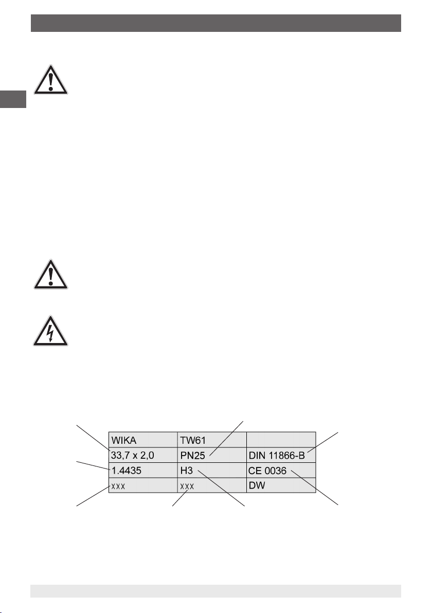
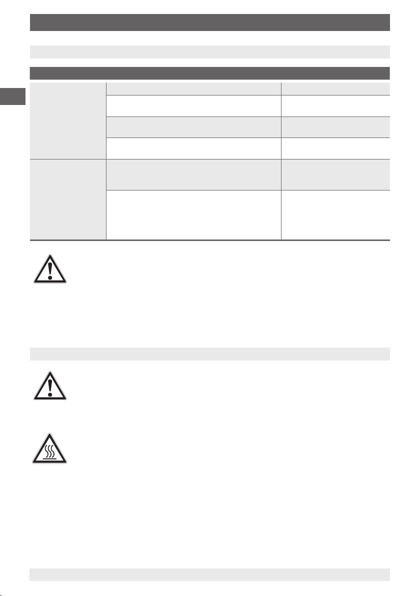
2.4 Labelling, safety marking
Outer diameter x wall thickness
Tubular body
material
Material code
(complete assembly)
6
Identication of the qualied
inspector (for stamping)
max. nominal pressure
Pipe standard
Hygiene class
WIKA operating instructions thermowell, model TW61
CE marking (required
for DN > 25 mm)
11593963.03 03/2014 GB/D/F/E
Page 7

3. Specications / 4. Design and function
3. Specications
Specications Model TW61
Designs of connection Flow-through housing or angular housing
Nominal width of tube Pipe classes per DIN, ISO and ASME BPE
see table of dimensions, chapter 4.2 “Dimensions and
Permissible temperature ranges
■
Ambient
■
Medium to be measured
Materials (wetted parts)
■
Pipes to DIN 11866 series A (metric) and
series B (ISO)
■
Pipes to DIN 11866 series C (ASME BPE)
Connection to the thermometer Model TR21-B: G 3/8 male
For further specications see WIKA data sheet TW 95.61 and the order documentation.
4. Design and function
4.1 Description
The model TW61 thermowell is used to adapt thermometers and measuring inserts to the
process and protects the sensor against harsh process conditions. Furthermore, it enables the
removal of the temperature sensor without having to open the process.
pressure ratings”
-40 ... +85 °C
-50 ... +250 °C
Stainless steel 1.4435
Stainless steel 316L
Model TR22-B: M24 x 1.5 rotatable male nut
GB
To integrate it into the process, the thermowell is directly orbitally-welded into a pipeline. The
connection ends are smooth and prepared for orbital welding.
In combination with a resistance thermometer, the rotatable threaded connection of the
connection head or the display can be loosened and turned to the desired orientation. The
measuring insert can be withdrawn together with the connection head. In this way, it is possible to
calibrate the entire measuring chain (sensor, transmitter if applicable, connection cable) on site,
without having to disconnect the electrical connection. In addition this avoids having to open the
process, and thus the risk of contamination is minimised.
The thermowell is not piggable.
11593963.03 03/2014 GB/D/F/E
WIKA operating instructions thermowell, model TW61
7
Page 8
4. Design and function
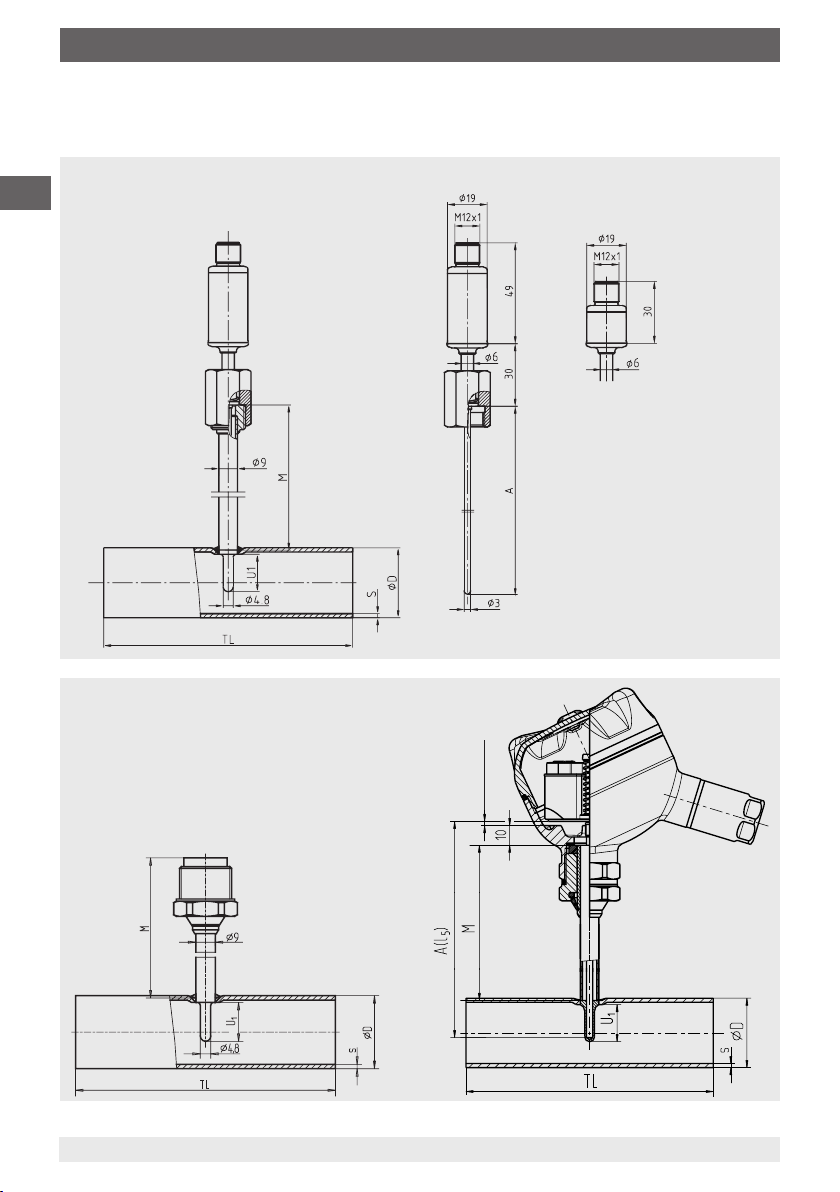
4.2 Dimensions in mm
■
Flow-through housing
For model TR21-B miniature resistance thermometer
GB
Output signal
4 ... 20 mA
1)
Output signal
Pt100
1) In the event of replacement,
calculate sensor length, A,
as follows:
A
= U1 + M + 3 mm
TR21-B
11610565.01
For model TR22-B resistance thermometer
1) In the event of replacement, select a resistance thermometer
measuring insert model TR22-B.
The corresponding sensor length, A(l5), is calculated as follows:
Insertion length U1+ neck tube length M + 5 mm pre-load +
10 mm head dimension
11528266.01
8
pre-load
1)
WIKA operating instructions thermowell, model TW61
14006093.02
11593963.03 03/2014 GB/D/F/E
Page 9

4. Design and function
Metric or DIN 11866 series A
Nominal
width of
tube
OD PN
10 25 13 1.5 70 6 51 129
15 25 19 1.5 70 9 48 126
20 25 23 1.5 80 11 46 124
25 25 29 1.5 100 18 39 117
32 25 35 1.5 110 18 39 117
40 25 41 1.5 120 18 39 117
50 25 53 1.5 160 30 27 105
65 16 70 2.0 210 30 27 105
80 16 85 2.0 260 45 12 90
100 12.5 104 2.0 310 45 12 90
Nominal
pressure
in bar
1) 2)
Outer
diameter
Tube wall
thickness
Tube
length
of pipe
Ø D s TL U
Thermowell
insertion
length
1
ISO tubes or DIN 11866 series B
Nominal
width of
tube
OD PN
13.5 25 13.5 1.6 64 6 51 129
17.2 25 17.2 1.6 68 9 48 126
21.3 25 21.3 1.6 72 11 46 124
26.9 25 26.9 1.6 110 11 46 124
33.7 25 33.7 2.0 120 18 39 117
42.4 25 42.4 2.0 130 18 39 117
48.3 25 48.3 2.0 130 18 39 117
60.3 25 60.3 2.0 180 30 27 105
76.1 16 76.1 2.0 220 30 27 105
88.9 16 88.9 2.3 260 45 12 90
Nominal
pressure
in bar
1) 2)
Outer
diameter
Tube wall
thickness
Tube
length
of pipe
Ø D s TL U
Thermowell
insertion
length
1
Neck tube length
TR21-B TR22-B
M M
Neck tube length
TR21-B TR22-B
M M
GB
ASME BPE or DIN 11866 series C
Nominal
width of
tube
OD PN
½" 13.8 12.7 1.65 95.2 6 51 129
¾" 13.8 19.05 1.65 101.6 9 48 126
1" 13.8 25.4 1.65 108.0 11 46 124
1 ½" 13.8 38.1 1.65 120.6 18 39 117
2" 13.8 50.8 1.65 146.0 18 39 117
2 ½" 13.8 63.5 1.65 158.8 30 27 105
3" 13.8 76.2 1.65 171.4 30 27 105
4" 13.8 101.6 2.11 209.6 45 12 90
1) Maximum operating temperature 150 °C
2) All thermowells of this model series which are exposed to internal pressure and have a nominal diameter (DN) of > 25 mm are
manufactured and tested in accordance with module H of the pressure equipment directive 97/23/EC.
11593963.03 03/2014 GB/D/F/E
WIKA operating instructions thermowell, model TW61
Nominal
pressure
in bar
1) 2)
Outer
diameter
Tube wall
thickness
Tube
length
of pipe
Ø D s TL U
Thermowell
insertion
length
1
Neck tube length
TR21-B TR22-B
M M
9
Page 10
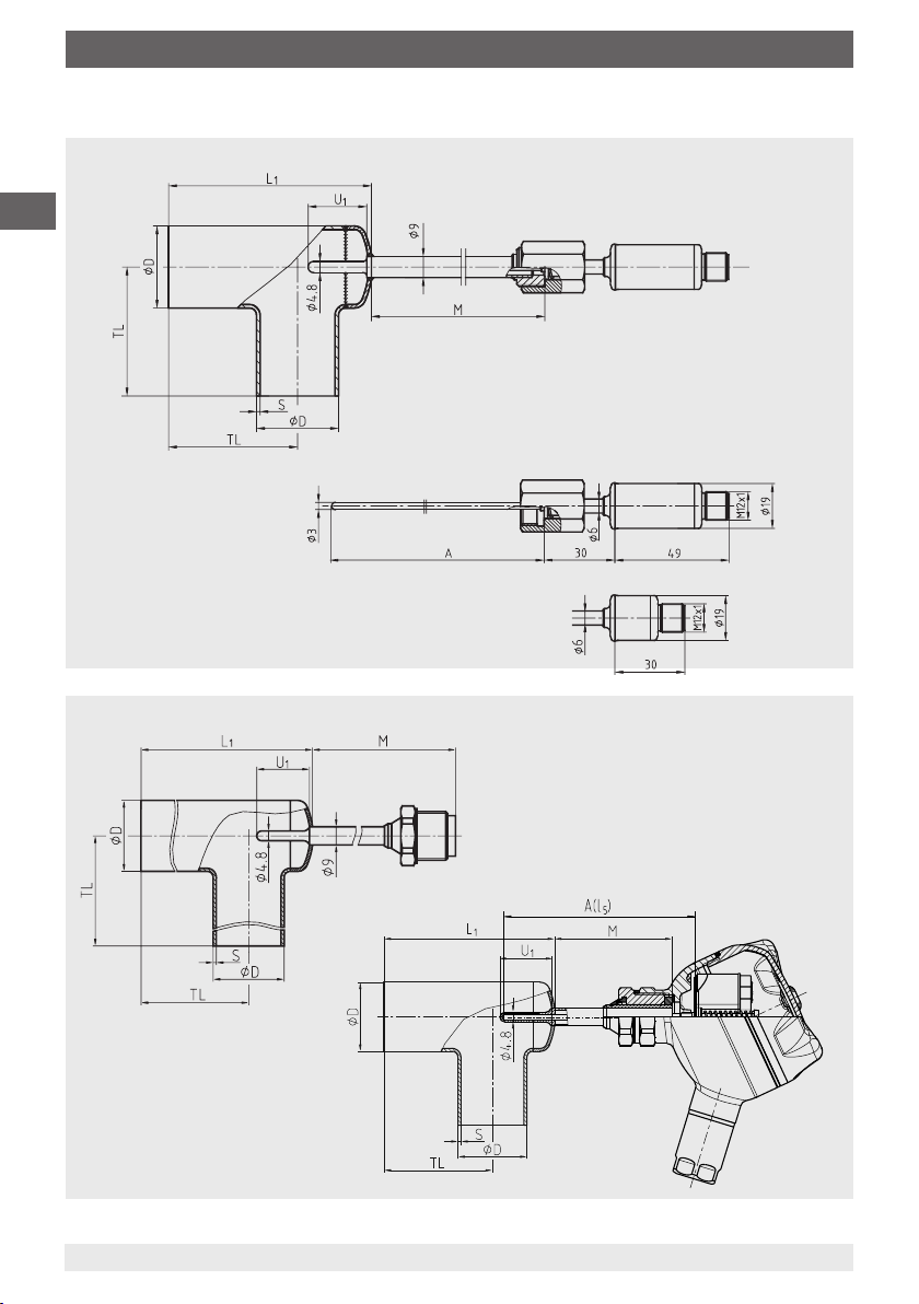
4. Design and function
■
Angular housing (recommended mounting position, see chapter 6 “Commissioning, operation”)
For model TR21-B miniature resistance thermometer
GB
Output signal
4 ... 20 mA
11610565.01
1)
1) In the event of replacement, calculate
sensor length, A, as follows:
A
= U1 + M + 3 mm
TR21-B
For model TR22-B resistance thermometer
10
Output signal
Pt100
1) In the event of replacement, select a resistance
thermometer measuring insert model TR22-B.
The corresponding sensor length, A(l5), is
calculated as follows:
11528452.01
Insertion length U1+ neck tube length M +
5 mm pre-load + 10 mm head dimension
WIKA operating instructions thermowell, model TW61
11575795.02
11593963.03 03/2014 GB/D/F/E
Page 11

4. Design and function
Metric or DIN 11866 series A
Nominal
width of
tube
OD PN
10 25 13 1.5 35 55 14 43 121
15 25 19 1.5 35 55 18 39 117
20 25 23 1.5 40 63 18 39 117
25 25 29 1.5 50 77 30 27 105
32 25 35 1.5 55 87 30 27 105
40 25 41 1.5 60 97 30 27 105
50 25 53 1.5 80 126 30 27 105
65 16 70 2.0 105 165 45 12 90
80 16 85 2.0 130 201 45 12 90
100 12.5 104 2.0 155 241 45 12 90
Nominal
pressure
in bar
1) 2)
Outer
diameter
Tube wall
thickness
Tube
length
of pipe
Ø D s TL L
Thermowell
insertion
length
U
1
1
ISO tubes or DIN 11866 series B
Nominal
width of
tube
OD PN
13.5 25 13.5 1.6 32 55 14 43 121
17.2 25 17.2 1.6 34 55 16 41 119
21.3 25 21.3 1.6 36 58 18 39 117
26.9 25 26.9 1.6 55 81 30 27 105
33.7 25 33.7 2.0 60 91 30 27 105
42.4 25 42.4 2.0 65 102 30 27 105
48.3 25 48.3 2.0 65 108 30 27 105
60.3 25 60.3 2.0 90 145 45 12 90
76.1 16 76.1 2.0 110 173 45 12 90
88.9 16 88.9 2.3 130 203 45 12 90
Nominal
pressure
in bar
1) 2)
Outer
diameter
Tube wall
thickness
Tube
length
of pipe
Ø D s TL L
Thermowell
insertion
length
U
1
1
Neck tube length
TR21-B TR22-B
M M
Neck tube length
TR21-B TR22-B
M M
GB
ASME BPE or DIN 11866 series C
Nominal
width of
tube
OD PN
½" 13.8 12.7 1.65 47.6 71 14 43 121
¾" 13.8 19.05 1.65 50.8 71 18 39 117
1" 13.8 25.4 1.65 54.0 79 18 39 117
1 ½" 13.8 38.1 1.65 60.3 94 30 27 105
2" 13.8 50.8 1.65 73.0 118 30 27 105
2 ½" 13.8 63.5 1.65 79.4 134 45 12 90
3" 13.8 76.2 1.65 85.7 150 45 12 90
4" 13.8 101.6 2.11 104.8 190 45 12 90
1) Maximum operating temperature 150 °C
2) All thermowells of this model series which are exposed to internal pressure and have a nominal diameter (DN) of > 25 mm are
manufactured and tested in accordance with module H of the pressure equipment directive 97/23/EC.
Nominal
pressure
in bar
1) 2)
Outer
diameter
Tube wall
thickness
Tube
length
of pipe
Ø D s TL L
Thermowell
insertion
length
U
1
1
Neck tube length
TR21-B TR22-B
M M
4.3 Scope of delivery
Cross-check the scope of delivery with the delivery note.
11593963.03 03/2014 GB/D/F/E
WIKA operating instructions thermowell, model TW61
11
Page 12
5. Transport, packaging and storage / 6. Commissioning, ...
5. Transport, packaging and storage
5.1 Transport
Check the thermowell for any damage that may have been caused by transport.
Obvious damage must be reported immediately.
GB
5.2 Packaging
Do not remove packaging until just before mounting.
Keep the packaging as it will provide optimum protection during transport (e.g. change in
installation site, sending for repair).
5.3 Storage
Permissible conditions at the place of storage:
■
Storage temperature: 0 ... 70 °C
■
Humidity: 35 ... 85 % relative humidity (no condensation)
WARNING!
Before storing the thermowell (following operation), remove any residual media. This
is of particular importance if the medium is hazardous to health, e.g. caustic, toxic,
carcinogenic, radioactive, etc.
6. Commissioning, operation
CAUTION!
Before commissioning the thermowell, clean the plant in accordance with the
cleaning specications.
The thermowell must not be bent or altered in order to mount it. The tting should be carried
out such that there can be no damage to the thermowell as a result of the plant operation or the
operator. If necessary, one of the thermowell/pipeline mountings mentioned below (e.g. using a
pipe clamp) will be required. In particular, the neck should be secured by appropriate methods
against bending.
Version for orbital welding
In the orbital welding version, the TW61 is directly welded into the pipeline. Weld the thermowell
centered, without axial oset (without irregularities), orbitally in the pipeline.The weld joint should
therefore be made with appropriate care and in line with the applicable and accredited welding
procedures and tested. Likewise, the requirements of the 97/23/EC pressure equipment directive
should be followed.
For general information on the design of a hygienic weld, we recommend the following
documents (among others):
■
EHEDG guideline 35 - Welding of stainless steel tubing in the food industry
■
EHEDG guideline 9 - Welding stainless steel to meet hygienic requirements
■
EHEDG guideline 8 - Hygienic equipment design criteria, 7.5
■
3-A® sanitary standard for sensors and sensor ttings, number 74-06, D 6.1.4
12
WIKA operating instructions thermowell, model TW61
11593963.03 03/2014 GB/D/F/E
Page 13
6. Commissioning, operation / 7. Maintenance and cleaning
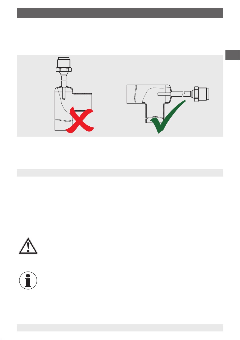
Recommended installation for the angular housing design
Concerning the angular housing design it is recommended, to install the sensor horizontally and
not vertically in the pipeline. Consequently the formation of an air pocket during sterilization in the
cupola is avoided.
7. Maintenance and cleaning
GB
7.1 Maintenance
In general, thermowells are maintenance-free.
We recommend a visual check of the thermowell for leaks and damages at regular intervals.
Make sure that the seal is in perfect condition!
Repairs should only be carried out by the manufacturer or, following prior consultation, by
correspondingly qualied skilled personnel.
7.2 Cleaning
CAUTION!
■
Wash or clean the dismounted instrument before returning it, in order to protect
personnel and the environment from exposure to residual media.
■
Residual media in the dismounted thermowell can result in a risk to persons, the
environment and equipment. Sucient precautionary measures must be taken.
For information on returning the instrument see chapter 9.2 “Return”.
11593963.03 03/2014 GB/D/F/E
WIKA operating instructions thermowell, model TW61
13
Page 14
8. Faults / 9. Dismounting, return and disposal
8. Faults
Faults Causes Measures
Not possible
GB
to insert the
temperature sensor
into the thermowell
Escape of process
medium
CAUTION!
If faults cannot be eliminated by means of the measures listed above, shut down the
instrument immediately, and ensure that pressure and/or signal are no longer present,
and secure the instrument from being put back into operation inadvertently.
In this case, contact the manufacturer.
If a return is needed, follow the instructions given in chapter 9.2 “Return”.
Foreign bodies in the thermowell Remove foreign bodies
Damaged or contaminated fastening thread on
thermowell or temperature sensor
Damaged fastening thread on thermowell or
temperature sensor
Thermowell or sensor has been bent or
damaged during installation
Where there is an escape of process medium
at the process connection, errors in mounting or
faulty seals can be the cause.
Should process media escape at the interface
between the thermowell and the temperature
sensor or at the temperature sensor itself,
safe operation of the plant can no longer be
guaranteed
Clean the threads
Return the thermowell
(see chapter 9.2 “Returns”)
Return for repair
Check the seal and also
check the tightening torques
Remove the thermowell from
operation and contact WIKA
9. Dismounting, return and disposal
WARNING!
Residual media in the dismounted thermowell can result in a risk to persons, the
environment and equipment. Sucient precautionary measures must be taken.
9.1 Dismounting
WARNING!
Risk of burns!
Let the instrument cool down suciently before dismounting! During dismounting
there is a risk of dangerously hot pressure media escaping.
Only disconnect thermowells once the system has been depressurised!
14
WIKA operating instructions thermowell, model TW61
11593963.03 03/2014 GB/D/F/E
Page 15
9. Dismounting, return and disposal
9.2 Return
WARNING!
Absolutely observe the following when shipping the instrument:
All instruments delivered to WIKA must be free from any kind of hazardous
substances (acids, leachate, solutions, etc.).
When returning the instrument, use the original packaging or a suitable transport package.
To avoid damage:
1. Wrap the instrument in an antistatic plastic lm.
2. Place the instrument, along with shock-absorbent material, in the packaging.
Place shock-absorbent material evenly on all sides of the shipping box.
3. If possible, place a bag containing a desiccant inside the packaging.
4. Label the shipment as carriage of a highly sensitive measuring instrument.
Information on returns can be found under the heading „Service“ on our local
website.
9.3 Disposal
Incorrect disposal can put the environment at risk.
Dispose of instrument components and packaging materials in an environmentally compatible
way and in accordance with the country-specic waste disposal regulations.
GB
11593963.03 03/2014 GB/D/F/E
WIKA operating instructions thermowell, model TW61
15
Page 16
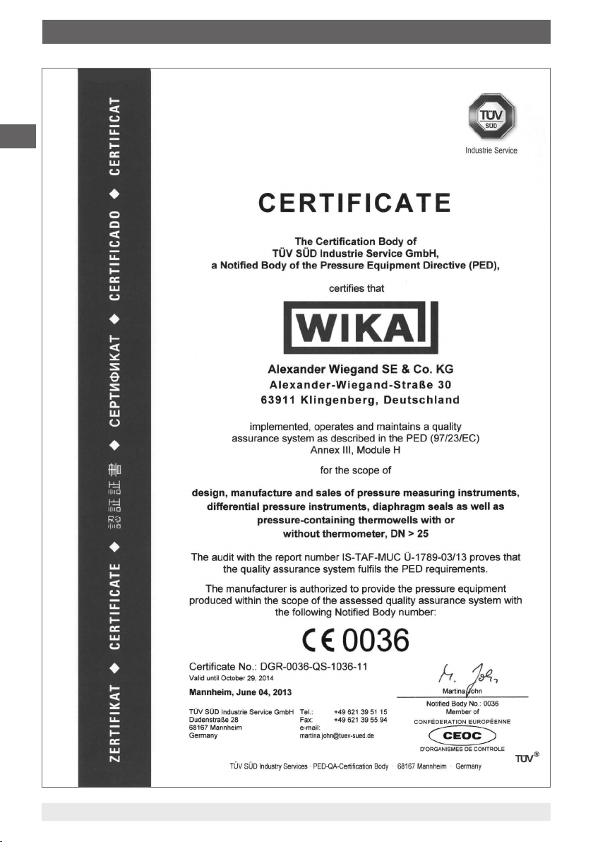
Appendix 1: TÜV certicate
GB
16
11593963.03 03/2014 GB/D/F/E
WIKA operating instructions thermowell, model TW61
Page 17
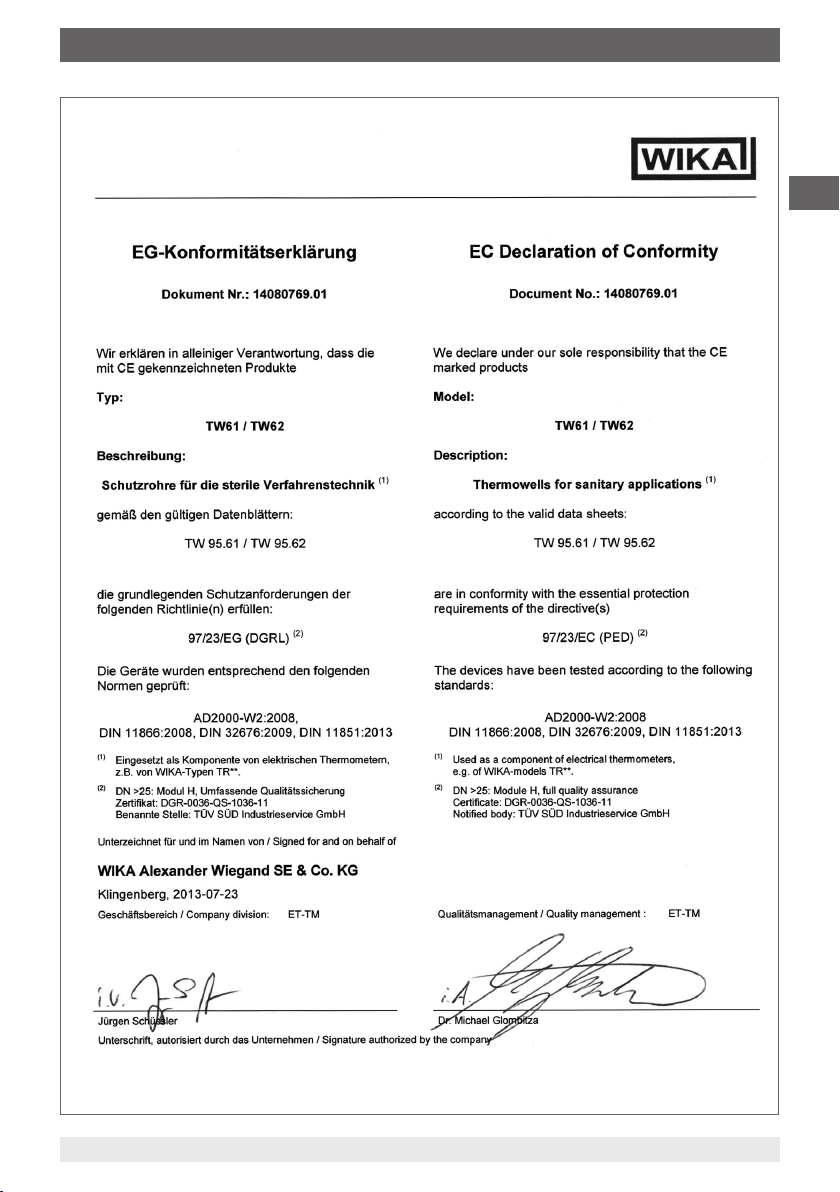
Appendix 2: EC declaration of conformity
GB
11593963.03 03/2014 GB/D/F/E
WIKA operating instructions thermowell, model TW61
17
Page 18

GB
18
11593963.03 03/2014 GB/D/F/E
WIKA operating instructions thermowell, model TW61
Page 19
Inhalt
Inhalt
1. Allgemeines 20
2. Sicherheit 21
3. Technische Daten 23
4. Aufbau und Funktion 23
5. Transport, Verpackung und Lagerung 28
6. Inbetriebnahme, Betrieb 28
Wartung und Reinigung
7.
8. Störungen 30
9. Demontage, Rücksendung und Entsorgung 30
Anlage 1: TÜV-Zertikat 32
Anlage 2: EG-Konformitätserklärung 34
Konformitätserklärungen nden Sie online unter www.wika.de.
29
D
11593963.03 03/2014 GB/D/F/E
WIKA Betriebsanleitung Schutzrohr, Typ TW61
19
Page 20
1. Allgemeines
1. Allgemeines
■
Die in der Betriebsanleitung beschriebenen Schutzrohre werden nach dem aktuellen Stand
der Technik gefertigt. Alle Komponenten unterliegen während der Fertigung strengen Qualitäts- und Umweltkriterien. Unsere Managementsysteme sind nach ISO 9001 und ISO 14001
zertiziert.
D
■
Diese Betriebsanleitung gibt wichtige Hinweise zum Umgang mit dem Schutzrohr.
Voraussetzung für sicheres Arbeiten ist die Einhaltung aller angegebenen Sicherheitshinweise
und Handlungsanweisungen.
■
Die für den Einsatzbereich des Schutzrohres geltenden örtlichen Unfallverhütungsvorschriften
und allgemeinen Sicherheitsbestimmungen einhalten.
■
Die Betriebsanleitung ist Produktbestandteil und muss in unmittelbarer Nähe des
Schutzrohres für das Fachpersonal jederzeit zugänglich aufbewahrt werden.
■
Das Fachpersonal muss die Betriebsanleitung vor Beginn aller Arbeiten sorgfältig durchgelesen und verstanden haben.
■
Die Haftung des Herstellers erlischt bei Schäden durch bestimmungswidrige Verwendung,
Nichtbeachten dieser Betriebsanleitung, Einsatz ungenügend qualizierten Fachpersonals
sowie eigenmächtiger Veränderung am Schutzrohr.
■
Es gelten die allgemeinen Geschäftsbedingungen in den Verkaufsunterlagen.
■
Technische Änderungen vorbehalten.
■
Weitere Informationen:
- Internet-Adresse: www.wika.de / www.wika.com
- zugehöriges Datenblatt:
- Anwendungsberater:
TW 95.61
Tel.: +49 9372 132-0
Fax: +49 9372 132-406
info@wika.de
Symbolerklärung
WARNUNG!
… weist auf eine möglicherweise gefährliche Situation hin, die zum Tod oder zu
schweren Verletzungen führen kann, wenn sie nicht gemieden wird.
VORSICHT!
… weist auf eine möglicherweise gefährliche Situation hin, die zu geringfügigen oder
leichten Verletzungen bzw. Sach- und Umweltschäden führen kann, wenn sie nicht
gemieden wird.
Information
… hebt nützliche Tipps und Empfehlungen sowie Informationen für einen ezienten
und störungsfreien Betrieb hervor.
20
WIKA Betriebsanleitung Schutzrohr, Typ TW61
11593963.03 03/2014 GB/D/F/E
Page 21
1. Allgemeines / 2. Sicherheit
GEFAHR!
… kennzeichnet Gefährdungen durch elektrischen Strom. Bei Nichtbeachtung der
Sicherheitshinweise besteht die Gefahr schwerer oder tödlicher Verletzungen.
WARNUNG!
… weist auf eine möglicherweise gefährliche Situation hin, die durch heiße
Oberächen oder Flüssigkeiten zu Verbrennungen führen kann, wenn sie nicht
gemieden wird.
2. Sicherheit
WARNUNG!
Vor Montage, Inbetriebnahme und Betrieb sicherstellen, dass das richtige Schutzrohr
hinsichtlich Ausführung und spezischen Messbedingungen ausgewählt wurde.
Vor Montage, Inbetriebnahme und Betrieb sicherstellen, dass der verwendete
Schutzrohrwerksto gegenüber dem Messmedium chemisch beständig/neutral ist,
sowie den prozessseitigen mechanischen Belastungen stand hält.
Bei Nichtbeachten können schwere Körperverletzungen und/oder Sachschäden
auftreten.
Weitere wichtige Sicherheitshinweise benden sich in den einzelnen Kapiteln dieser
Betriebsanleitung.
D
2.1 Bestimmungsgemäße Verwendung
Schutzrohre dienen zum Schutz des Temperaturfühlers gegenüber den Prozessbedingungen.
Des Weiteren ermöglichen Schutzrohre den Ausbau des Temperaturfühlers ohne den Prozess
stillzulegen und verhindern Umwelt- oder Personenschäden durch den Austritt von Prozessmedium. Das Schutzrohr Typ TW61 wurde speziell für den Einsatz in der sterilen Verfahrenstechnik entwickelt.
Das Schutzrohr ist ausschließlich für den hier beschriebenen bestimmungsgemäßen Verwendungszweck konzipiert und konstruiert und darf nur dementsprechend verwendet werden.
Die technischen Spezikationen in dieser Betriebsanleitung sind einzuhalten. Eine unsachgemäße Handhabung oder ein Betreiben des Gerätes außerhalb der technischen Spezikationen
macht die sofortige Stilllegung und Überprüfung durch einen autorisierten WIKA-Servicemitarbeiter erforderlich.
Ansprüche jeglicher Art aufgrund von nicht bestimmungsgemäßer Verwendung sind
ausgeschlossen.
11593963.03 03/2014 GB/D/F/E
WIKA Betriebsanleitung Schutzrohr, Typ TW61
21
Page 22

2. Sicherheit
2.2 Personalqualikation
WARNUNG!
Verletzungsgefahr bei unzureichender Qualikation!
Unsachgemäßer Umgang kann zu erheblichen Personen- und Sachschäden führen.
■
Die in dieser Betriebsanleitung beschriebenen Tätigkeiten nur durch Fachpersonal
nachfolgend beschriebener Qualikation durchführen lassen.
■
D
Fachpersonal
Das Fachpersonal ist aufgrund seiner fachlichen Ausbildung, seiner Kenntnisse der Mess- und
Regelungstechnik und seiner Erfahrungen sowie Kenntnis der landesspezischen Vorschriften,
geltenden Normen und Richtlinien in der Lage, die beschriebenen Arbeiten auszuführen und
mögliche Gefahren selbstständig zu erkennen.
Spezielle Einsatzbedingungen verlangen weiteres entsprechendes Wissen, z. B. über agressive
Medien.
2.3 Besondere Gefahren
Unqualiziertes Personal von den Gefahrenbereichen fernhalten.
WARNUNG!
Bei gefährlichen Messstoen wie z. B. Sauersto, Acetylen, brennbaren oder giftigen
Stoen, sowie bei Kälteanlagen, Kompressoren etc. müssen über die gesamten
allgemeinen Regeln hinaus die einschlägigen Vorschriften beachtet werden.
GEFAHR!
Auf ausreichende Erdung des Schutzrohres achten.
2.4 Beschilderung, Sicherheitskennzeichnungen
Außendurchmesser x Wandstärke
Material
Rohrkörper
Materialcode
(Baugruppe komplett)
22
Kurzzeichen des
Umstempelberechtigten Prüfers
max. Nenndruck
Rohrnorm
Hygieneklasse
WIKA Betriebsanleitung Schutzrohr, Typ TW61
CE-Kennzeichen
(erforderlich DN > 25 mm)
11593963.03 03/2014 GB/D/F/E
Page 23

3. Technische Daten / 4. Aufbau und Funktion
3. Technische Daten
Technische Daten Typ TW61
Bauformen Durchgangsgehäuse oder Eckgehäuse
Rohr-Nennweite Rohrklassen nach DIN, ISO und ASME BPE
Zulässige Temperaturbereiche
■
Umgebung
■
Messmedium
Werkstoe (messstofberührte
Bauteile)
■
Rohre nach DIN 11866 Reihe A
(metrisch) und Reihe B (ISO)
■
Rohre nach DIN 11866 Reihe C
(ASME BPE)
Anschluss zum Thermometer Typ TR21-B: G 3/8 Außengewinde
Weitere technische Daten siehe WIKA-Datenblatt TW 95.61 und Bestellunterlagen.
4. Aufbau und Funktion
4.1 Beschreibung
Das Schutzrohr Typ TW61 dient zur Prozessadaption eines Thermometers bzw. Messeinsatzes
und schützt den Sensor vor rauen Prozessbedingungen. Des Weiteren ermöglicht es den
Ausbau des Temperaturfühlers ohne den Prozess önen zu müssen.
siehe Maßtabellen Kapitel 4.2 „Abmessungen und Druckstufen“
-40 ... +85 °C
-50 ... +250 °C
CrNi-Stahl 1.4435
CrNi-Stahl 316L
Typ TR22-B: Druckschraube M24 x 1,5 drehbar
D
Für die Einbindung in den Prozess wird das Schutzrohr direkt orbital in eine Rohrleitung eingeschweißt. Die Anschlussenden sind glatt und zum Orbitalschweißen vorbereitet.
Bei einer Kombination mit einem Widerstandsthermometer lassen sich durch die drehbare
Verschraubung der Anschlusskopf oder die Anzeige lösen und in die gewünschte Richtung
drehen. Der Messeinsatz ist zusammen mit Anschlusskopf herausziehbar. Dadurch ist es
möglich, die gesamte Messkette (Sensor, ggf. Transmitter, Anschlusskabel) vor Ort zu kalibrieren, ohne Abklemmen der elektrischen Anschlüsse. Zudem wird es vermieden, den Prozess zu
önen und damit ein Hygienerisiko minimiert.
Das Schutzrohr ist nicht molchbar.
11593963.03 03/2014 GB/D/F/E
WIKA Betriebsanleitung Schutzrohr, Typ TW61
23
Page 24

4. Aufbau und Funktion
4.2 Abmessungen in mm
■
Durchgangsgehäuse
Für Miniatur-Widerstandsthermometer Typ TR21-B
D
11610565.01
Ausgangssignal
Pt100
1)
Für Widerstandsthermometer Typ TR22-B
1) Im Ersatzfall ist ein Widerstandsthermometer-Messeinsatz
Typ TR22-B zu wählen.
Die entsprechende Sensorlänge A(l5) errechnet sich wie folgt:
Einbaulänge U1+ Halsrohrlänge M + 5 mm Vorspannung +
10 mm Kopfmaß
24
Ausgangssignal
4 ... 20 mA
Vorspannung
11528266.01
1)
1) Im Ersatzfall errechnet sich
die Sensorlänge A wie folgt:
A
TR21-B
WIKA Betriebsanleitung Schutzrohr, Typ TW61
= U1 + M + 3 mm
14006093.02
11593963.03 03/2014 GB/D/F/E
Page 25

4. Aufbau und Funktion
Metrisch bzw. DIN 11866 Reihe A
RohrNennweite
OD PN
10 25 13 1,5 70 6 51 129
15 25 19 1,5 70 9 48 126
20 25 23 1,5 80 11 46 124
25 25 29 1,5 100 18 39 117
32 25 35 1,5 110 18 39 117
40 25 41 1,5 120 18 39 117
50 25 53 1,5 160 30 27 105
65 16 70 2,0 210 30 27 105
80 16 85 2,0 260 45 12 90
100 12,5 104 2,0 310 45 12 90
Nenndruck
in bar
1) 2)
Rohraußen-Ø
Ø D s TL U
Rohrwandstärke
Rohrlänge
Schutzrohreinbaulänge
1
ISO-Rohre bzw. DIN 11866 Reihe B
RohrNennweite
OD PN
13,5 25 13,5 1,6 64 6 51 129
17,2 25 17,2 1,6 68 9 48 126
21,3 25 21,3 1,6 72 11 46 124
26,9 25 26,9 1,6 110 11 46 124
33,7 25 33,7 2,0 120 18 39 117
42,4 25 42,4 2,0 130 18 39 117
48,3 25 48,3 2,0 130 18 39 117
60,3 25 60,3 2,0 180 30 27 105
76,1 16 76,1 2,0 220 30 27 105
88,9 16 88,9 2,3 260 45 12 90
Nenndruck
in bar
1) 2)
Rohraußen-Ø
Ø D s TL U
Rohrwandstärke
Rohrlänge
Schutzrohreinbaulänge
1
Halsrohrlänge
TR21-B TR22-B
M M
Halsrohrlänge
TR21-B TR22-B
M M
D
ASME BPE bzw. DIN 11866 Reihe C
RohrNennweite
OD PN
½" 13,8 12,7 1,65 95,2 6 51 129
¾" 13,8 19,05 1,65 101,6 9 48 126
1" 13,8 25,4 1,65 108,0 11 46 124
1 ½" 13,8 38,1 1,65 120,6 18 39 117
2" 13,8 50,8 1,65 146,0 18 39 117
2 ½" 13,8 63,5 1,65 158,8 30 27 105
3" 13,8 76,2 1,65 171,4 30 27 105
4" 13,8 101,6 2,11 209,6 45 12 90
1) Maximale Betriebstemperatur 150 °C
2) Alle innendruckbeaufschlagte Schutzrohre dieser Typenreihe mit einem Nenndurchmesser (DN) > 25 mm werden nach Modul H der
Druckgeräterichtlinie 97/23/EG gefertigt und geprüft.
11593963.03 03/2014 GB/D/F/E
WIKA Betriebsanleitung Schutzrohr, Typ TW61
Nenndruck
in bar
1) 2)
Rohraußen-Ø
Ø D s TL U
Rohrwandstärke
Rohrlänge
Schutzrohreinbaulänge
1
Halsrohrlänge
TR21-B TR22-B
M M
25
Page 26

4. Aufbau und Funktion
■
Eckgehäuse (empfohlene Einbaulage, siehe Kapitel 6 „Inbetriebnahme, Betrieb“)
Für Miniatur-Widerstandsthermometer Typ TR21-B
D
Ausgangssignal
4 ... 20 mA
1) Im Ersatzfall errechnet sich die
Sensorlänge A wie folgt:
A
= U1 + M + 3 mm
TR21-B
Für Widerstandsthermometer Typ TR22-B
1)
Ausgangssignal
Pt100
11528452.01
1) Im Ersatzfall ist ein WiderstandsthermometerMesseinsatz Typ TR22-B zu wählen.
Die entsprechende Sensorlänge A(l5) errechnet
sich wie folgt:
Einbaulänge U1+ Halsrohrlänge M + 5 mm
Vorspannung + 10 mm Kopfmaß
11610565.01
26
11575795.02
11593963.03 03/2014 GB/D/F/E
WIKA Betriebsanleitung Schutzrohr, Typ TW61
Page 27

4. Aufbau und Funktion
Metrisch bzw. DIN 11866 Reihe A
RohrNennweite
OD PN
10 25 13 1,5 35 55 14 43 121
15 25 19 1,5 35 55 18 39 117
20 25 23 1,5 40 63 18 39 117
25 25 29 1,5 50 77 30 27 105
32 25 35 1,5 55 87 30 27 105
40 25 41 1,5 60 97 30 27 105
50 25 53 1,5 80 126 30 27 105
65 16 70 2,0 105 165 45 12 90
80 16 85 2,0 130 201 45 12 90
100 12,5 104 2,0 155 241 45 12 90
Nenndruck
in bar
1) 2)
Rohraußen-Ø
Ø D s TL L1U
Rohrwandstärke
Rohrlänge Schutzrohr-
einbaulänge
1
ISO-Rohre bzw. DIN 11866 Reihe B
RohrNennweite
OD PN
13,5 25 13,5 1,6 32 55 14 43 121
17,2 25 17,2 1,6 34 55 16 41 119
21,3 25 21,3 1,6 36 58 18 39 117
26,9 25 26,9 1,6 55 81 30 27 105
33,7 25 33,7 2,0 60 91 30 27 105
42,4 25 42,4 2,0 65 102 30 27 105
48,3 25 48,3 2,0 65 108 30 27 105
60,3 25 60,3 2,0 90 145 45 12 90
76,1 16 76,1 2,0 110 173 45 12 90
88,9 16 88,9 2,3 130 203 45 12 90
Nenndruck
in bar
1) 2)
Rohraußen-Ø
Ø D s TL L1U
Rohrwandstärke
Rohrlänge Schutzrohr-
einbaulänge
1
Halsrohrlänge
TR21-B TR22-B
M M
Halsrohrlänge
TR21-B TR22-B
M M
D
ASME BPE bzw. DIN 11866 Reihe C
RohrNennweite
OD PN
½" 13,8 12,7 1,65 47,6 71 14 43 121
¾" 13,8 19,05 1,65 50,8 71 18 39 117
1" 13,8 25,4 1,65 54,0 79 18 39 117
1 ½" 13,8 38,1 1,65 60,3 94 30 27 105
2" 13,8 50,8 1,65 73,0 118 30 27 105
2 ½" 13,8 63,5 1,65 79,4 134 45 12 90
3" 13,8 76,2 1,65 85,7 150 45 12 90
4" 13,8 101,6 2,11 104,8 190 45 12 90
1) Maximale Betriebstemperatur 150 °C
2) Alle innendruckbeaufschlagte Schutzrohre dieser Typenreihe mit einem Nenndurchmesser (DN) > 25 mm werden nach Modul H der
Druckgeräterichtlinie 97/23/EG gefertigt und geprüft.
Nenndruck
in bar
1) 2)
Rohraußen-Ø
Ø D s TL L1U
Rohrwandstärke
Rohrlänge Schutzrohr-
einbaulänge
1
Halsrohrlänge
TR21-B TR22-B
M M
4.3 Lieferumfang
Lieferumfang mit dem Lieferschein abgleichen.
11593963.03 03/2014 GB/D/F/E
WIKA Betriebsanleitung Schutzrohr, Typ TW61
27
Page 28

5. Transport, Verpackung, Lagerung / 6. Inbetriebnahme, ...
5. Transport, Verpackung und Lagerung
5.1 Transport
Das Schutzrohr auf eventuell vorhandene Transportschäden untersuchen.
Oensichtliche Schäden unverzüglich mitteilen.
5.2 Verpackung
D
Verpackung erst unmittelbar vor der Montage entfernen.
Die Verpackung aufbewahren, denn diese bietet bei einem Transport einen optimalen Schutz
(z. B. wechselnder Einbauort, Reparatursendung).
5.3 Lagerung
Zulässige Bedingungen am Lagerort:
■
Lagertemperatur: 0 ... 70 °C
■
Feuchtigkeit: 35 ... 85 % relative Feuchte (keine Betauung)
WARNUNG!
Vor der Einlagerung des Schutzrohres (nach Betrieb) alle anhaftenden Messstoreste entfernen. Dies ist besonders wichtig, wenn der Messsto gesundheitsgefähr-
dend ist, wie z. B. ätzend, giftig, krebserregend, radioaktiv, usw.
6. Inbetriebnahme, Betrieb
VORSICHT!
Vor Inbetriebnahme das Schutzrohr entsprechend den Reinigungsvorschriften der
Anlage reinigen.
Ein Verbiegen oder Anpassen des Schutzrohres zur Montage ist nicht zulässig. Der Einbau hat
so zu erfolgen, dass Beschädigungen des Schutzrohres durch den Anlagenbetrieb oder den
Anwender ausgeschlossen werden. Gegebenenfalls ist dafür eine über die unten beschriebene hinausgehende Befestigung des Schutzrohres/der Rohrleitung (z. B. mittels Rohrschellen)
notwendig. Insbesondere der Hals ist durch geeignete Maßnahmen vor Abknicken zu schützen.
Ausführung zum orbitalen Einschweißen
In der Ausführung zum orbitalen Einschweißen ist das TW61 direkt in die Rohrleitung einzuschweißen. Das Schutzrohr zentrisch ohne Achsversatz (stufenfrei) in die Rohrleitung orbital
einschweißen. Die Schweißverbindung ist dabei mit der erforderlichen Sorgfalt und unter Beachtung der gültigen und anerkannten Schweißverfahren herzustellen und zu prüfen. Ebenso sind
die Vorgaben der Druckgeräterichtlinie 97/23/EG zu beachten.
Für generelle Hinweise zur Ausführung einer hygienegerechten Schweißverbindung empfehlen
sich u.a. folgende Dokumente:
■
EHEDG Guideline 35 - Welding of stainless steel tubing in the food industry
■
EHEDG Guideline 9 - Welding stainless steel to meet hygienic requirements
■
EHEDG Guideline 8 - Hygienic equipment design criteria, 7.5
■
3-A® sanitary standard for sensors and sensor ttings, number 74-06, D 6.1.4
28
WIKA Betriebsanleitung Schutzrohr, Typ TW61
11593963.03 03/2014 GB/D/F/E
Page 29

6. Inbetriebnahme, Betrieb / 7. Wartung und Reinigung
Einbauempfehlung für die Ausführung mit Eckgehäuse
Bei der Ausführung mit Eckgehäuse wird empfohlen, den Fühler waagerecht und nicht
senkrecht in die Rohrleitung einzubauen. Somit wird die Bildung eines Luftpolsters während der
Sterilisation im Dom vermieden.
7. Wartung und Reinigung
7.1 Wartung
Schutzrohre sind im Allgemeinen wartungsfrei.
Empfohlen wird eine Sichtüberprüfung des Schutzrohres auf Leckagen oder Beschädigungen in
regelmäßigen Intervallen. Insbesondere auf einwandfreie Funktion der Dichtung achten!
D
Reparaturen sind ausschließlich vom Hersteller oder nach Absprache durch entsprechend
qualiziertes Fachpersonal durchzuführen.
7.2 Reinigung
VORSICHT!
■
Ausgebautes Gerät vor der Rücksendung spülen bzw. säubern, um Mitarbeiter
und Umwelt vor Gefährdung durch anhaftende Messstoreste zu schützen.
■
Messstoreste an ausgebauten Schutzrohren können zur Gefährdung von
Personen, Umwelt und Einrichtung führen. Ausreichende Vorsichtsmaßnahmen
sind zu ergreifen.
Hinweise zur Rücksendung des Gerätes siehe Kapitel 9.2 „Rücksendung“.
11593963.03 03/2014 GB/D/F/E
WIKA Betriebsanleitung Schutzrohr, Typ TW61
29
Page 30

8. Störungen / 9. Demontage, Rücksendung und Entsorgung
8. Störungen
Störungen Ursachen Maßnahmen
Temperaturfühler
lässt sich nicht in
das Schutzrohr
einführen
D
Austritt von Prozessmedium
VORSICHT!
Können Störungen mit Hilfe der oben aufgeführten Maßnahmen nicht beseitigt werden,
ist das Gerät unverzüglich außer Betrieb zu setzen, sicherzustellen, dass kein Druck
bzw. Signal mehr anliegt und gegen versehentliche Inbetriebnahme zu schützen.
In diesem Falle Kontakt mit dem Hersteller aufnehmen.
Bei notwendiger Rücksendung die Hinweise siehe Kapitel 9.2 „Rücksendung“
beachten.
Fremdkörper im Schutzrohr Fremdkörper entfernen
Verschmutzte Befestigungsgewinde von
Schutzrohr oder Temperaturfühler
Beschädigte Befestigungsgewinde von
Schutzrohr oder Temperaturfühler
Schutzrohr oder Fühler wurde bei Montage
verbogen oder beschädigt
Bei Austritt von Prozessmedium am
Prozessanschluss können Fehler bei der
Montage oder fehlerhafte Dichtungen die
Ursache sein.
Tritt Prozessmedium an der Schnittstelle des
Schutzrohres zu Temperaturfühler oder am
Temperaturfühler selbst aus ist ein sicherer
Betrieb der Anlage nicht mehr gewährleistet
Gewinde reinigen
Schutzrohr zurücksenden
(siehe Kapitel 9.2 „Rücksendung“)
Zur Reparatur zurück senden
Dichtung überprüfen sowie die
Anzugsmomente kontrollieren
Schutzrohr außer Betrieb setzen
und Kontakt mit WIKA aufnehmen
9. Demontage, Rücksendung und Entsorgung
WARNUNG!
Messstoreste an ausgebauten Schutzrohren können zur Gefährdung von Personen,
Umwelt und Einrichtung führen. Ausreichende Vorsichtsmaßnahmen sind zu
ergreifen.
9.1 Demontage
WARNUNG!
Verbrennungsgefahr!
Vor dem Ausbau das Gerät ausreichend abkühlen lassen! Beim Ausbau besteht
Gefahr durch austretende, gefährlich heiße Messstoe.
Schutzrohre nur im drucklosen Zustand demontieren!
30
WIKA Betriebsanleitung Schutzrohr, Typ TW61
11593963.03 03/2014 GB/D/F/E
Page 31

9. Demontage, Rücksendung und Entsorgung
9.2 Rücksendung
WARNUNG!
Beim Versand des Gerätes unbedingt beachten:
Alle an WIKA gelieferten Geräte müssen frei von Gefahrstoen (Säuren, Laugen,
Lösungen, etc.) sein.
Zur Rücksendung des Gerätes die Originalverpackung oder eine geeignete Transportverpackung
verwenden.
Um Schäden zu vermeiden:
1. Das Gerät in eine antistatische Plastikfolie einhüllen.
2. Das Gerät mit dem Dämmmaterial in der Verpackung platzieren.
Zu allen Seiten der Transportverpackung gleichmäßig dämmen.
3. Wenn möglich einen Beutel mit Trocknungsmittel der Verpackung beifügen.
4. Sendung als Transport eines hochempndlichen Messgerätes kennzeichnen.
Hinweise zur Rücksendung benden sich in der Rubrik „Service“ auf unserer lokalen
Internetseite.
9.3 Entsorgung
Durch falsche Entsorgung können Gefahren für die Umwelt entstehen.
Gerätekomponenten und Verpackungsmaterialien entsprechend den landesspezischen
Abfallbehandlungs- und Entsorgungsvorschriften umweltgerecht entsorgen.
D
11593963.03 03/2014 GB/D/F/E
WIKA Betriebsanleitung Schutzrohr, Typ TW61
31
Page 32

Anlage 1: TÜV-Zertikat
D
32
11593963.03 03/2014 GB/D/F/E
WIKA Betriebsanleitung Schutzrohr, Typ TW61
Page 33

Anlage 2: EG-Konformitätserklärung
D
11593963.03 03/2014 GB/D/F/E
WIKA Betriebsanleitung Schutzrohr, Typ TW61
33
Page 34

D
34
11593963.03 03/2014 GB/D/F/E
WIKA Betriebsanleitung Schutzrohr, Typ TW61
Page 35

Sommaire
Sommaire
1. Généralités 36
2. Sécurité 37
3. Spécications 39
4. Conception et fonction 39
5. Transport, emballage et stockage 44
6. Mise en service, exploitation 44
Entretien et nettoyage
7.
8. Dysfonctionnements 46
9. Démontage, retour et mise au rebut 46
Annexe 1 : Certicat du TÜV (contrôle technique allemand) 48
Annexe 2 : Déclaration de conformité CE 49
Déclarations de conformité se trouve sur www.wika.fr.
45
F
11593963.03 03/2014 GB/D/F/E
WIKA mode d'emploi doigt de gant, type TW61
35
Page 36

1. Généralités
1. Généralités
■
Les doigts de gant décrits dans ce mode d'emploi sont conçus et fabriqués selon les
dernières technologies en vigueur. Tous les composants sont soumis à des critères de qualité
et d'environnement stricts durant la fabrication. Nos systèmes de gestion sont certiés selon
ISO 9001 et ISO 14001.
■
Ce mode d'emploi donne des indications importantes concernant l'utilisation du doigt de
gant. Il est possible de travailler en toute sécurité avec ce produit en respectant toutes les
F
consignes de sécurité et d'utilisation.
■
Respecter les prescriptions locales de prévention contre les accidents et les prescriptions
générales de sécurité en vigueur pour le domaine d'application du doigt de gant.
■
Le mode d'emploi fait partie du produit et doit être conservé à proximité immédiate du doigt de
gant et être accessible à tout moment pour le personnel qualié.
■
Le personnel qualié doit, avant de commencer toute opération, avoir lu soigneusement et
compris le mode d'emploi.
■
La responsabilité du fabricant n'est pas engagée en cas de dommages provoqués par une
utilisation non conforme à l'usage prévu, de non respect de ce mode d'emploi, d'utilisation de
personnel peu qualié de même qu'en cas de modications du doigt de gant eectuées par
l'utilisateur.
■
Les conditions générales de vente mentionnées dans les documents de vente s'appliquent.
■
Sous réserve de modications techniques.
■
Pour obtenir d‘autres informations:
- Consulter notre site internet : www.wika.fr
- Fiche technique correspondante :
- Conseiller applications :
TW 95.61
Tel. : +33 1 343084-84
Fax : +33 1 343084-94
info@wika.fr
Explication des symboles
AVERTISSEMENT !
… indique une situation présentant des risques susceptibles de provoquer la mort ou
des blessures graves si elle n'est pas évitée.
ATTENTION !
… indique une situation potentiellement dangereuse et susceptible de provoquer de
légères blessures ou des dommages matériels et pour l'environnement si elle n'est
pas évitée.
Information
… met en exergue les conseils et recommandations utiles de même que les
informations permettant d'assurer un fonctionnement ecace et normal.
36
11593963.03 03/2014 GB/D/F/E
WIKA mode d'emploi doigt de gant, type TW61
Page 37

1. Généralités / 2. Sécurité
DANGER !
… indique les dangers liés au courant électrique. Danger de blessures graves ou
mortelles en cas de non respect des consignes de sécurité.
AVERTISSEMENT !
… indique une situation présentant des risques susceptibles de provoquer des
brûlures dues à des surfaces ou liquides chauds si elle n'est pas évitée.
2. Sécurité
AVERTISSEMENT !
Avant le montage, la mise en service et le fonctionnement, s'assurer que la gaine
a été choisie de façon adéquate, en ce qui concerne la version et les conditions de
mesure spéciques.
Avant l'installation, la mise en service et l'utilisation, assurez-vous que le matériau
utilisé pour le doigt de gant est chimiquement résistant/neutre au uide qui est
mesuré et qu'il résiste aux contraintes mécaniques venant du processus.
Un non-respect de cette consigne peut entraîner des blessures corporelles graves et/
ou des dégâts matériels.
Vous trouverez d'autres consignes de sécurité dans les sections individuelles du
présent mode d'emploi.
F
2.1 Utilisation conforme à l'usage prévu
Les doigts de gant sont utilisés pour protéger les capteurs de température des conditions de
process. Les doigts de gant permettent en outre le retrait du capteur de température sans avoir
à arrêter le process; ils permettent également d'éviter tout dommage pour l'environnement ou le
personnel pouvant résulter d'un écoulement de uide de process. Le doigt de gant type TW61 a
été spécialement conçu pour être utilisé dans des applications sanitaires.
Le doigt de gant est conçu et construit exclusivement pour une utilisation conforme à l'usage
prévu décrit ici et ne doit être utilisé qu'en conséquence.
Les spécications techniques mentionnées dans ce mode d'emploi doivent être respectées. En
cas d'utilisation inadéquate ou de fonctionnement de l'instrument en dehors des spécications
techniques, un arrêt et contrôle doivent être immédiatement eectués par un collaborateur
autorisé du service de WIKA.
Aucune réclamation ne peut être recevable en cas d'utilisation non conforme à l'usage prévu.
11593963.03 03/2014 GB/D/F/E
WIKA mode d'emploi doigt de gant, type TW61
37
Page 38

2. Sécurité
2.2 Qualication du personnel
AVERTISSEMENT !
Danger de blessure en cas de qualication insusante !
Une utilisation non conforme peut entraîner d'importants dommages corporels et
matériels.
■
Les opérations décrites dans ce mode d'emploi ne doivent être eectuées que par
un personnel ayant la qualication décrite ci-après.
■
Tenir le personnel non qualié à lécart des zones dangereuses.
F
Personnel qualié
Le personnel qualié est, en raison de sa formation spécialisée, de ses connaissances dans le
domaine de la technique de mesure et de régulation et de ses expériences de même que de
sa connaissance des prescriptions nationales, des normes et directives en vigueur, en mesure
d'eectuer les travaux décrits et de reconnaître automatiquement les dangers potentiels.
Les conditions d'utilisation spéciales exigent également une connaissance adéquate par
exemple des liquides agressifs.
2.3 Dangers particuliers
AVERTISSEMENT !
Dans le cas de uides de mesure dangereux comme notamment l'oxygène,
l'acétylène, les substances combustibles ou toxiques, ainsi que dans le cas
d'installations de réfrigération, de compresseurs etc., les directives appropriées
existantes doivent être observées en plus de l'ensemble des règles générales.
DANGER !
Assurez-vous que le doigt de gant est susamment mis à la terre.
2.4 Étiquetage, marquages de sécurité
Diamètre extérieur x épaisseur
Matériau du
corps tubulaire
Code du matériau
(assemblage complet)
38
Identication de l'inspecteur
qualié (pour l'homologation)
Pression nominale max.
Tuyauterie
standard
Classe hygiénique
WIKA mode d'emploi doigt de gant, type TW61
Marquage CE (requis
pour DN > 25 mm)
11593963.03 03/2014 GB/D/F/E
Page 39

3. Spécications / 4. Conception et fonction
3. Spécications
Spécications Type TW61
Formes du raccord Montage en ligne ou montage coudé
Taille nominale du tube Classes de tube selon DIN, ISO et ASME BPE
voir tableau des dimensions, chapitre 4.2 “Dimensions et
Plages de température admissibles
■
Ambiante
■
Fluide à mesurer
Matériaux (parties en contact avec le
uide)
■
Tuyauteries pour DIN 11866 série A
(métrique) et série B (ISO)
■
Tuyauteries pour DIN 11866 série C
(ASME BPE)
Raccord au thermomètre Type TR21-B : G 3/8 mâle
Pour de plus amples spécications, voir la che technique WIKA TW 95.61 et la documentation
de commande.
4. Conception et fonction
indications de pression”
-40 ... +85 °C
-50 ... +250 °C
Acier inox 1.4435
Acier inox 316L
Type TR22-B : raccord tournant M24 x 1,5
F
4.1 Description
Le doigt de gant type TW61 est utilisé pour adapter des thermomètres et des inserts de mesure
au process et pour protéger le capteur des conditions de process diciles. Il permet en outre le
retrait du capteur de température sans avoir à interrompre le process.
Pour l'intégration dans le process, le doigt de gant est soudé directement de manière orbitale
dans une conduite. Les extrémités de raccordement sont lisses et préparées pour la soudure
orbitale.
En combinaison avec une sonde à résistance, le raccordement leté tournant de la tête de
raccordement ou l'achage peuvent être desserrés et tournés dans l'orientation voulue. L'insert
de mesure peut être retiré avec la tête de raccordement. Ainsi, il est possible de calibrer la
totalité de la chaîne de mesure (capteur, transmetteur s'il est applicable, câble de connexion) sur
place, sans avoir à débrancher le raccordement électrique. En outre, ceci évite d'avoir à ouvrir le
process, et ainsi le risque de contamination est minimisé.
Le doigt de gant ne peut pas être raclé.
11593963.03 03/2014 GB/D/F/E
WIKA mode d'emploi doigt de gant, type TW61
39
Page 40

4. Conception et fonction
4.2 Dimensions en mm
■
Montage en ligne
Pour sonde à résistance miniature type TR21-B
F
Pour sonde à résistance miniature type TR22-B
1) Dans le cas d’un remplacement, choisir un insert de mesure pour la
sonde à résistance de type TR22-B.
La longueur correspondante du capteur, A(l5), est calculée comme suit :
Longueur d’insertion U1+ longueur totale extension M + 5 mm pré-charge
+ 10 mm dimension de la tête
Signal de sortie
4 ... 20 mA
pré-charge
1)
Signal de sortie
Pt100
1) En cas de remplacement,
calculer la longueur du
capteur, A, comme suit :
A
= U1 + M + 3 mm
TR21-B
11610565.01
14006093.02
40
11528266.01
1)
11593963.03 03/2014 GB/D/F/E
WIKA mode d'emploi doigt de gant, type TW61
Page 41

4. Conception et fonction
Métrique ou DIN 11866 série A
Taille
nominale
du tube
OD PN
10 25 13 1,5 70 6 51 129
15 25 19 1,5 70 9 48 126
20 25 23 1,5 80 11 46 124
25 25 29 1,5 100 18 39 117
32 25 35 1,5 110 18 39 117
40 25 41 1,5 120 18 39 117
50 25 53 1,5 160 30 27 105
65 16 70 2,0 210 30 27 105
80 16 85 2,0 260 45 12 90
100 12,5 104 2,0 310 45 12 90
Pression
nominale
en bar
1) 2)
Diamètre
extérieur de
la tuyauterie
Ø D s TL U
Epaisseur
de paroi de
la tuyauterie
Longueur
de tube
Longueur
d'insertion du
doigt de gant
1
Tuyauteries ISO ou DIN 11866 série B
Taille
nominale
du tube
OD PN
13,5 25 13,5 1,6 64 6 51 129
17,2 25 17,2 1,6 68 9 48 126
21,3 25 21,3 1,6 72 11 46 124
26,9 25 26,9 1,6 110 11 46 124
33,7 25 33,7 2,0 120 18 39 117
42,4 25 42,4 2,0 130 18 39 117
48,3 25 48,3 2,0 130 18 39 117
60,3 25 60,3 2,0 180 30 27 105
76,1 16 76,1 2,0 220 30 27 105
88,9 16 88,9 2,3 260 45 12 90
Pression
nominale
en bar
1) 2)
Diamètre
extérieur de
la tuyauterie
Ø D s TL U
Epaisseur
de paroi de
la tuyauterie
Longueur
de tube
Longueur
d'insertion du
doigt de gant
1
Longueur totale
extension
TR21-B TR22-B
M M
Longueur totale
extension
TR21-B TR22-B
M M
F
ASME BPE ou DIN 11866 série C
Taille
nominale
du tube
OD PN
½" 13,8 12,7 1,65 95,2 6 51 129
¾" 13,8 19,05 1,65 101,6 9 48 126
1" 13,8 25,4 1,65 108,0 11 46 124
1 ½" 13,8 38,1 1,65 120,6 18 39 117
2" 13,8 50,8 1,65 146,0 18 39 117
2 ½" 13,8 63,5 1,65 158,8 30 27 105
3" 13,8 76,2 1,65 171,4 30 27 105
4" 13,8 101,6 2,11 209,6 45 12 90
1) Température maximale d’exploitation 150 °C
2) Tous les doigts de gant de cette série qui sont exposés à la pression interne et ont un diamètre nominal (DN) de > 25 mm sont
fabriqués et testés en conformité avec le module H de la directive sur les équipements sous pression 97/23/CE.
11593963.03 03/2014 GB/D/F/E
WIKA mode d'emploi doigt de gant, type TW61
Pression
nominale
en bar
1) 2)
Diamètre
extérieur de
la tuyauterie
Ø D s TL U
Epaisseur
de paroi de
la tuyauterie
Longueur
de tube
Longueur
d'insertion du
doigt de gant
1
Longueur totale
extension
TR21-B TR22-B
M M
41
Page 42

4. Conception et fonction
■
Montage angulaire (position de montage recommandée, voir chapitre 6 “Mise en service,
exploitation”)
Pour sonde à résistance miniature type TR21-B
F
Signal de sortie
4 ... 20 mA
1) En cas de remplacement, calculer la
longueur du capteur, A, comme suit :
A
= U1 + M + 3 mm
TR21-B
1)
Signal de sortie
Pt100
11610565.01
Pour sonde à résistance miniature type TR22-B
42
1) Dans le cas d’un remplacement, choisir un insert de
mesure pour la sonde à résistance de type TR22-B.
La longueur correspondante du capteur, A(l5), est
calculée comme suit :
Longueur d’insertion U1+ longueur totale extension
M + 5 mm pré-charge + 10 mm dimension de la tête
11528452.01
WIKA mode d'emploi doigt de gant, type TW61
11575795.02
11593963.03 03/2014 GB/D/F/E
Page 43

4. Conception et fonction
Métrique ou DIN 11866 série A
Taille
nominale
du tube
OD PN
10 25 13 1,5 35 55 14 43 121
15 25 19 1,5 35 55 18 39 117
20 25 23 1,5 40 63 18 39 117
25 25 29 1,5 50 77 30 27 105
32 25 35 1,5 55 87 30 27 105
40 25 41 1,5 60 97 30 27 105
50 25 53 1,5 80 126 30 27 105
65 16 70 2,0 105 165 45 12 90
80 16 85 2,0 130 201 45 12 90
100 12,5 104 2,0 155 241 45 12 90
Pression
nominale
en bar
1) 2)
Diamètre
extérieur de
la tuyauterie
Ø D s TL L1U
Epaisseur
de paroi de
la tuyauterie
Longueur
de tube
Longueur
d'insertion du
doigt de gant
1
Tuyauteries ISO ou DIN 11866 série B
Taille
nominale
du tube
OD PN
13,5 25 13,5 1,6 32 55 14 43 121
17,2 25 17,2 1,6 34 55 16 41 119
21,3 25 21,3 1,6 36 58 18 39 117
26,9 25 26,9 1,6 55 81 30 27 105
33,7 25 33,7 2,0 60 91 30 27 105
42,4 25 42,4 2,0 65 102 30 27 105
48,3 25 48,3 2,0 65 108 30 27 105
60,3 25 60,3 2,0 90 145 45 12 90
76,1 16 76,1 2,0 110 173 45 12 90
88,9 16 88,9 2,3 130 203 45 12 90
Pression
nominale
en bar
1) 2)
Diamètre
extérieur de
la tuyauterie
Ø D s TL L1U
Epaisseur
de paroi de
la tuyauterie
Longueur
de tube
Longueur
d'insertion du
doigt de gant
1
Longueur totale
extension
TR21-B TR22-B
M M
Longueur totale
extension
TR21-B TR22-B
M M
F
ASME BPE ou DIN 11866 série C
Taille
nominale
du tube
OD PN
½
" 13,8 12,7 1,65 47,6 71 14 43 121
¾
" 13,8 19,05 1,65 50,8 71 18 39 117
1" 13,8 25,4 1,65 54,0 79 18 39 117
½
1
2" 13,8 50,8 1,65 73,0 118 30 27 105
½
2
3" 13,8 76,2 1,65 85,7 150 45 12 90
4" 13,8 101,6 2,11 104,8 190 45 12 90
1) Température maximale d’exploitation 150 °C
2) Tous les doigts de gant de cette série qui sont exposés à la pression interne et ont un diamètre nominal (DN) de > 25 mm sont
fabriqués et testés en conformité avec le module H de la directive sur les équipements sous pression 97/23/CE.
Pression
nominale
en bar
" 13,8 38,1 1,65 60,3 94 30 27 105
" 13,8 63,5 1,65 79,4 134 45 12 90
Diamètre
extérieur de
la tuyauterie
1) 2)
Ø D s TL L1U
Epaisseur
de paroi de
la tuyauterie
Longueur
de tube
Longueur
d'insertion du
doigt de gant
1
Longueur totale
extension
TR21-B TR22-B
M M
4.3 Détail de la livraison
Comparer le détail de la livraison avec le bordereau de livraison.
11593963.03 03/2014 GB/D/F/E
WIKA mode d'emploi doigt de gant, type TW61
43
Page 44

5. Transport, emballage et stockage / 6. Mise en service, ...
5. Transport, emballage et stockage
5.1 Transport
Vérier s'il existe des dégâts sur le doigt de gant liés au transport.
Communiquer immédiatement les dégâts constatés.
5.2 Emballage
N'enlever l'emballage qu'avant le montage.
Conserver l'emballage, celui-ci ore, lors d'un transport, une protection optimale (par ex.
F
changement de lieu d'utilisation, renvoi pour réparation).
5.3 Stockage
Conditions admissibles sur le lieu de stockage :
■
Température de stockage : 0 ... 70 °C
■
Humidité : 35 ... 85 % d‘humidité relative (sans condensation)
AVERTISSEMENT !
Enlever tous les restes de uides adhérents avant l'entreposage du doigt de gant
(après le fonctionnement). Ceci est particulièrement important lorsque le uide
représente un danger pour la santé, comme par exemple des substances corrosives,
toxiques, cancérogènes, radioactives etc.
6. Mise en service, exploitation
ATTENTION !
Avant de mettre en service le doigt de gant, nettoyer les installations dans le respect
des consignes de nettoyage.
Le doigt de gant ne doit pas être plié ou modié pour le montage. L'installation doit être
eectuée de sorte qu'il n'y ait aucun dommage causé au doigt de gant par le fonctionnement
de l'installation ou par l'opérateur. Si nécessaire, il faudra avoir une des installations de doigts
de gant/de conduites mentionnées plus bas (par exemple en utilisant un collier de serrage). En
particulier, le col sera protégé par des méthodes appropriées contre toute courbure.
Exécution pour soudure orbitale
Dans l'exécution pour soudure orbitale, le TW61 est soudé directement dans la conduite. Souder
le doigt de gant de manière centrée et sans décalage de l‘axe (sans étages) dans la conduite par
soudage orbital. La jointure de soudure devra donc être eectuée avec le soin requis et être en ligne
avec les procédures applicables et accréditées et ensuite testée. De manière similaire, les exigences
de la directive 97/23/CE concernant les équipements de pression doivent être respectées.
Pour obtenir des informations générales concernant la conception d'une liaison soudée
hygiénique, nous recommandons les documents suivants (entre autres) :
■
EHEDG Guideline 35 - Welding of stainless steel tubing in the food industry
■
EHEDG Guideline 9 - Welding stainless steel to meet hygienic requirements
■
EHEDG Guideline 8 - Hygienic equipment design criteria, 7.5
■
3-A® sanitary standard for sensors and sensor ttings, number 74-06, D 6.1.4
44
WIKA mode d'emploi doigt de gant, type TW61
11593963.03 03/2014 GB/D/F/E
Page 45

6. Mise en service, exploitation / 7. Entretien et nettoyage
Installation recommandée pour la version pour montage angulaire
Concernant la version pour montage angulaire, il est recommandé d'installer le capteur à
l'horizontale et non verticalement dans la tuyauterie. De cette façon, on évite la formation d'une
poche d'air dans la coupole pendant la stérilisation.
7. Entretien et nettoyage
F
7.1 Entretien
En général, les doigts de gant ne nécessitent aucune maintenance.
Nous recommandons de procéder à un contrôle visuel des doigts de gant à la recherche de
fuites et de détériorations à intervalles réguliers. Assurez-vous que les joints sont en parfait état !
Toute réparation doit être conée exclusivement au fabricant ou, après consultation préalable de
WIKA, à un personnel qualié.
7.2 Nettoyage
ATTENTION !
■
Laver ou nettoyer l'instrument démonté avant de le retourner an de protéger le
personnel et l'environnement contre le danger lié aux restes de uides adhérents.
■
Les restes de uides se trouvant dans les doigts de gant démontés peuvent mettre
en danger les personnes, l'environnement ainsi que l'installation. Des mesures de
sécurité susantes doivent être prises.
Indications concernant le retour de l'instrument, voir chapitre 9.2 “Retour”.
11593963.03 03/2014 GB/D/F/E
WIKA mode d'emploi doigt de gant, type TW61
45
Page 46

8. Dysfonctionnements / 9. Démontage, retour, mise au rebut
8. Dysfonctionnements
Dysfonctionnements
Impossible d'insérer
le capteur de
température dans le
doigt de gant
F
En fuite du uide de
process
Raisons Mesures
Présence de corps étrangers dans le doigt de gant Retirer les corps étrangers
Filetage de xation du doigt de gant ou du capteur
de température endommagé ou contaminé
Filetage de xation du doigt de gant ou du capteur
de température endommagé
Le doigt de gant ou le capteur a été tordu ou
endommagé pendant l'installation
Lorsque le uide de process fuit au niveau du
raccord process, la raison peut en être des erreurs
de montage ou des joint d'étanchéité défectueux
Si des uides de process s'échappent à l'interface
entre le doigt de gant et le capteur de température
ou au niveau du capteur de température lui-même,
un fonctionnement en toute sécurité de l'installation
ne peut plus être garanti
Nettoyer les letages
Renvoyer le doigt de gant
(voir chapitre 9.2 “Retour”)
Retour pour réparation
Vérier le joint et
également contrôler les
couples de serrage
Déconnecter le doigt de
gant et contacter WIKA
ATTENTION !
Si des dysfonctionnements ne peuvent pas être éliminées à l'aide des mesures
indiquées ci-dessus, arrêter immédiatement l'instrument et s'assurer de l'absence de
pression et/ou de signal. Puis, sécuriser l'instrument an d'empêcher toute remise en
service involontaire. Contacter dans ce cas le fabricant.
S'il est nécessaire de renvoyer l'instrument au fabricant, suivre les indications
mentionnées au chapitre 9.2 “Retour”.
9. Démontage, retour et mise au rebut
AVERTISSEMENT !
Les restes de uides se trouvant dans les doigts de gant démontés peuvent mettre
en danger les personnes, l'environnement ainsi que l'installation. Des mesures de
sécurité susantes doivent être prises.
9.1 Démontage
AVERTISSEMENT !
Danger de brûlure !
Avant le démontage, laisser refroidir susamment l'instrument ! Danger de brûlure lié
à la sortie de uides dangereux chauds.
Déconnecter les doigts de gant uniquement une fois que le système a été mis hors pression !
46
WIKA mode d'emploi doigt de gant, type TW61
11593963.03 03/2014 GB/D/F/E
Page 47

9. Démontage, retour et mise au rebut
9.2 Retour
AVERTISSEMENT !
Il faut absolument observer les consignes suivantes lors de l'expédition de
l'instrument :
Tous les instruments envoyés à WIKA doivent être exempts de toute substance
dangereuse (acides, lixiviats, solutions, etc.).
Pour retourner l'instrument, utiliser l'emballage original ou un emballage adapté pour le transport.
Pour éviter des dommages :
1. Emballer l'instrument dans une feuille de plastique antistatique.
2. Placer l'instrument avec le matériau isolant dans l'emballage.
Isoler de manière uniforme tous les côtés de l'emballage de transport.
3. Mettre si possible un sachet absorbeur d'humidité dans l'emballage.
4. Indiquer lors de l'envoi qu'il s'agit d'un instrument de mesure très sensible à transporter.
Des informations relatives à la procédure de retour de produit(s) défectueux sont
disponibles sur notre site internet au chapitre “Services”.
9.3 Mise au rebut
Une mise au rebut inadéquate peut entraîner des dangers pour l'environnement.
Eliminer les composants des instruments et les matériaux d'emballage conformément aux
prescriptions nationales pour le traitement et l'élimination des déchets et aux lois de protection
de l'environnement en vigueur.
F
11593963.03 03/2014 GB/D/F/E
WIKA mode d'emploi doigt de gant, type TW61
47
Page 48

Annexe 1 : Certicat du TÜV (contrôle technique allemand)
F
48
11593963.03 03/2014 GB/D/F/E
WIKA mode d'emploi doigt de gant, type TW61
Page 49

Annexe 2 : Déclaration de conformité CE
E
11593963.03 03/2014 GB/D/F/E
WIKA manual de instrucciones vaina, modelo TW61
49
Page 50

E
50
11593963.03 03/2014 GB/D/F/E
WIKA manual de instrucciones vaina, modelo TW61
Page 51

Contenido
Contenido
1. Información general 52
2. Seguridad 53
3. Datos técnicos 55
4. Diseño y función 55
5. Transporte, embalaje y almacenamiento 60
6. Puesta en servicio, funcionamiento 60
Mantenimiento y limpieza
7.
8. Fallos 62
9. Desmontaje, devolución y eliminación 62
Anexo 1: Certicado TÜV (Inspección Técnica) 64
Anexo 2: Declaración de conformidad CE 65
Declaraciones de conformidad puede encontrar en www.wika.es.
61
E
11593963.03 03/2014 GB/D/F/E
WIKA manual de instrucciones vaina, modelo TW61
51
Page 52

1. Información general
1. Información general
■
Las vainas descritas en el manual de instrucciones están fabricadas según el estado actual
de la técnica. Todos los componentes están sujetos a rigurosos criterios de calidad y medio
ambiente durante la producción. Nuestros sistemas de gestión están certicados según
ISO 9001 e ISO 14001.
■
Este manual de instrucciones proporciona indicaciones importantes acerca del manejo de
la vaina. Para un trabajo seguro, es imprescindible cumplir con todas las instrucciones de
seguridad y manejo indicadas.
■
Cumplir siempre las normativas sobre la prevención de accidentes y las normas de seguridad
E
en vigor en el lugar de utilización de la vaina.
■
El manual de instrucciones es una parte integrante del producto y debe guardarse en las
proximidades de la vaina, para que el personal especializado pueda consultarlo en cualquier
momento.
■
El personal especializado debe haber leído detenidamente y entendido el manual de
instrucciones antes de comenzar cualquier trabajo.
■
El fabricante queda exento de cualquier responsabilidad en caso de daños causados
por un uso no conforme a la nalidad prevista, la inobservancia del presente manual
de instrucciones, un manejo por personal insucientemente cualicado así como una
modicación no autorizada de la vaina.
■
Se aplican las condiciones generales de venta incluidas en la documentación de venta.
■
Modicaciones técnicas reservadas.
■
Para obtener más informaciones consultar:
- Página web: www.wika.es
- Hoja técnica correspondiente:
- Servicio técnico:
TW 95.61
Tel.: +34 933 938-630
Fax: +34 933 938-666
info@wika.es
Explicación de símbolos
¡ADVERTENCIA!
... indica una situación probablemente peligrosa que pueda causar la muerte o
lesiones graves si no se evita.
¡CUIDADO!
... indica una situación probablemente peligrosa que pueda causar lesiones leves o
medianas o daños materiales y medioambientales si no se evita.
Información
... marca consejos y recomendaciones útiles así como informaciones para una
utilización ecaz y libre de fallos.
52
11593963.03 03/2014 GB/D/F/E
WIKA manual de instrucciones vaina, modelo TW61
Page 53

1. Información general / 2. Seguridad
¡PELIGRO!
... indica riesgos causados por corriente eléctrica. Existe riesgo de lesiones graves o
mortales si no se observan estas indicaciones de seguridad.
¡ADVERTENCIA!
... indica una situación probablemente peligrosa que pueda causar quemaduras
debido a supercies o líquidos calientes si no se evita.
2. Seguridad
¡ADVERTENCIA!
Antes del montaje, la puesta en servicio y el funcionamiento asegurarse de que
se haya seleccionada la vaina adecuada con respecto a versión y condiciones de
medición especícas.
Antes del montaje, la puesta en servicio y el funcionamiento asegurarse de que
el material de la vaina sea químicamente resistente/neutral al medio de medir y
resistente a las cargas mecánicas durante el proceso.
Riesgo de lesiones graves y/o daños materiales en caso de inobservancia.
Los distintos capítulos de este manual de instrucciones contienen otras importantes
indicaciones de seguridad.
2.1 Uso conforme a lo previsto
Las vainas protegen el sensor de temperatura frente a condiciones de proceso adversas.
Además, posibilitan el desmontaje del sensor de temperatura sin tener que parar el proceso y
evitan daños al medio ambiente o a personas a causa de escape del medio de proceso. La vaina
modelo TW61 fue especialmente desarrollada para el uso en de procesos estériles.
La vaina ha sido diseñado y construido únicamente para la nalidad aquí descrita y debe
utilizarse en conformidad a la misma.
Deben observarse las especicaciones técnicas indicadas en este manual de instrucciones.
Si el instrumento se utilizó de forma no adecuada o fuera de las especicaciones técnicas, el
mismo deberá desactivarse inmediatamente y someterse al control de personal autorizado del
servicio técnico de WIKA.
E
No se admite ninguna reclamación debido a un manejo no adecuado.
11593963.03 03/2014 GB/D/F/E
WIKA manual de instrucciones vaina, modelo TW61
53
Page 54

2. Seguridad
2.2 Cualicación del personal
¡ADVERTENCIA!
¡Riesgo de lesiones debido a una insuciente cualicación!
Un manejo no adecuado puede causar considerables daños personales y materiales.
■
Las actividades descritas en este manual de instrucciones deben realizarse
únicamente por personal especializado con la consiguiente cualicación.
■
Mantener alejado a personal no cualicado de las zonas peligrosas.
Personal especializado
Debido a su formación profesional, a sus conocimientos de la técnica de regulación y medición
así como a su experiencia y su conocimiento de las normativas, normas y directivas vigentes
E
en el país de utilización, el personal especializado está en condiciones de ejecutar los trabajos
descritos y reconocer posibles peligros en forma autónoma.
Algunas condiciones de uso especícas requieren conocimientos adicionales, p. ej. acerca de
medios agresivos.
2.3 Riesgos especícos
¡ADVERTENCIA!
En el caso de sustancias peligrosas a medir, como p. ej. oxígeno, acetileno, sustan-
cias inamables o tóxicas, así como en instalaciones de refrigeración, compresores,
etc., deben observarse en cada caso, además de todas las reglas generales, las
disposiciones pertinentes.
¡PELIGRO!
Prestar atención a que la vaina esté debidamente puesta a tierra.
2.4 Rótulos, marcados de seguridad
Diámetro exterior x grosor de la pared
Material de
la tubería
Código del material
(grupo completo)
54
Identicación del inspector
con autorización de estampar
máx. presión nominal
Normativa de la
tubería
Clase de higiene
WIKA manual de instrucciones vaina, modelo TW61
Marca CE (imprescindible
para DN > 25 mm)
11593963.03 03/2014 GB/D/F/E
Page 55

3. Datos técnicos / 4. Diseño y función
3. Datos técnicos
Datos técnicos Modelo TW61
Diseño Caja de paso o caja angular
Ancho nominal del tubo Clases de tubo según DIN, ISO y ASME BPE
véase la tabla de medidas en el capítulo
Rangos de temperatura admisibles
■
Ambiente
■
Medio medido
Materiales (componentes en contacto con la
sustancia)
■
Tubos según DIN 11866 serie A (métrico) y
serie B (ISO)
■
Tubos según DIN 11866 serie C (ASME BPE)
Conexión al termómetro Modelo TR21-B: G 3/8 rosca exterior
Para más datos técnicos véase la hoja técnica de WIKA TW 95.61 y la documentación de
pedido.
4. Diseño y función
4.2 “Dimensiones y niveles de presión”
-40 ... +85 °C
-50 ... +250 °C
Acero inoxidable 1.4435
Acero inoxidable 316L
Modelo TR22-B: tornillo de apriete M24 x 1,5
giratorio
E
4.1 Descripción
La vaina modelo TW61 es adecuada para la adaptación de un termómetro o dispositivo de
medición al proceso, y protege protege el sensor contra efectos causadas por condiciones de
proceso adversas. Además, permite el desmontaje del sensor de temperatura sin tener que abrir
el proceso.
Para la integración en el proceso, la vaina se suelda directamente a la tubería mediante
soldadura orbital. Los extremos de conexión son lisos y están preparados para este tipo de
soldadura.
En la versión con una termorresistencia, el cabezal de conexión o el indicador pueden orientarse
en la dirección deseada mediante el racor girable. La unidad de medida es extraíble junto
con el cabezal. Este sistema permite calibrar toda la cadena de medición (sensor, transmisor
-si existe-, cable de conexión) in situ, sin tener que desconectar las conexiones eléctricas.
Además, se evita abrir el proceso, minimizando así un riesgo de higiene.
La vaina no puede limpiarse con rascatubos.
11593963.03 03/2014 GB/D/F/E
WIKA manual de instrucciones vaina, modelo TW61
55
Page 56

4. Diseño y función
4.2 Dimensiones en mm
■
Caja de paso
Para termorresistencia miniatura modelo TR21-B
E
Señal de salida
4 ... 20 mA
1)
Señal de salida
Pt100
1) En caso de sustitución, la
longitud del sensor A se
calcula como sigue:
A
= U1 + M + 3 mm
TR21-B
11610565.01
Para termorresistencia miniatura modelo TR22-B
1) En caso de sustitución debe escogerse una unidad extraíble para
una termorresistencia del modelo TR22-B.
La correspondiente longitud del sensor A(I5) se calcula como sigue:
Longitud de montaje U1+ longitud del tubo de cuello M +
5 mm pretensión + 10 mm medida de la cabeza
11528266.01
56
WIKA manual de instrucciones vaina, modelo TW61
Pretensión
14006093.02
1)
11593963.03 03/2014 GB/D/F/E
Page 57

4. Diseño y función
Métrico o DIN 11866 serie A
Ancho
nominal
del tubo
OD PN
10 25 13 1,5 70 6 51 129
15 25 19 1,5 70 9 48 126
20 25 23 1,5 80 11 46 124
25 25 29 1,5 100 18 39 117
32 25 35 1,5 110 18 39 117
40 25 41 1,5 120 18 39 117
50 25 53 1,5 160 30 27 105
65 16 70 2,0 210 30 27 105
80 16 85 2,0 260 45 12 90
100 12,5 104 2,0 310 45 12 90
Presión
nominal
en bar
1) 2)
Diámetro
exterior
Espesor de
pared tubo
Longitud
tubo
del tubo
Ø D s TL U
Longitud de
montaje de
vaina
1
Tubos ISO o DIN 11866 serie B
Ancho
nominal
del tubo
OD PN
13,5 25 13,5 1,6 64 6 51 129
17,2 25 17,2 1,6 68 9 48 126
21,3 25 21,3 1,6 72 11 46 124
26,9 25 26,9 1,6 110 11 46 124
33,7 25 33,7 2,0 120 18 39 117
42,4 25 42,4 2,0 130 18 39 117
48,3 25 48,3 2,0 130 18 39 117
60,3 25 60,3 2,0 180 30 27 105
76,1 16 76,1 2,0 220 30 27 105
88,9 16 88,9 2,3 260 45 12 90
Presión
nominal
en bar
1) 2)
Diámetro
exterior
Espesor de
pared tubo
Longitud
tubo
del tubo
Ø D s TL U
Longitud de
montaje de
vaina
1
Longitud de
cuello
TR21-B TR22-B
M M
Longitud de
cuello
TR21-B TR22-B
M M
E
ASME BPE o DIN 11866 serie C
Ancho
nominal
del tubo
OD PN
½" 13,8 12,7 1,65 95,2 6 51 129
¾" 13,8 19,05 1,65 101,6 9 48 126
1" 13,8 25,4 1,65 108,0 11 46 124
1 ½" 13,8 38,1 1,65 120,6 18 39 117
2" 13,8 50,8 1,65 146,0 18 39 117
2 ½" 13,8 63,5 1,65 158,8 30 27 105
3" 13,8 76,2 1,65 171,4 30 27 105
4" 13,8 101,6 2,11 209,6 45 12 90
1) Temperatura máxima de servicio 150 °C
2) Todas las vainas sometidas a presión interior de esta serie con un diámetro nominal (DN) > 25 mm se fabrican según módulo H de la
directiva de equipos a presión 97/23 EG.
11593963.03 03/2014 GB/D/F/E
WIKA manual de instrucciones vaina, modelo TW61
Presión
nominal
en bar
1) 2)
Diámetro
exterior
Espesor de
pared tubo
Longitud
tubo
del tubo
Ø D s TL U
Longitud de
montaje de
vaina
1
Longitud de
cuello
TR21-B TR22-B
M M
57
Page 58

4. Diseño y función
■
Caja angular (posición de montaje recomendada, véase capítulo 6 “Puesta en servicio,
funcionamiento”)
Para termorresistencia miniatura modelo TR21-B
E
Señal de salida
4 ... 20 mA
1) En caso de sustitución, la longitud
del sensor A se calcula como sigue:
A
= U1 + M + 3 mm
TR21-B
1)
Señal de salida
Pt100
11610565.01
Para termorresistencia miniatura modelo TR22-B
58
WIKA manual de instrucciones vaina, modelo TW61
1) En caso de sustitución debe escogerse una unidad
extraíble para una termorresistencia del modelo TR22-B.
La correspondiente longitud del sensor A(I5) se calcula
como sigue:
Longitud de montaje U1+ longitud del tubo de cuello M
+ 5 mm pretensión + 10 mm medida de la cabeza
11528452.01
11575795.02
11593963.03 03/2014 GB/D/F/E
Page 59

4. Diseño y función
Métrico o DIN 11866 serie A
Ancho
nominal
del tubo
OD PN
10 25 13 1,5 35 55 14 43 121
15 25 19 1,5 35 55 18 39 117
20 25 23 1,5 40 63 18 39 117
25 25 29 1,5 50 77 30 27 105
32 25 35 1,5 55 87 30 27 105
40 25 41 1,5 60 97 30 27 105
50 25 53 1,5 80 126 30 27 105
65 16 70 2,0 105 165 45 12 90
80 16 85 2,0 130 201 45 12 90
100 12,5 104 2,0 155 241 45 12 90
Presión
nominal
en bar
1) 2)
Diámetro
exterior del
tubo
Ø D s TL L
Espesor de
pared tubo
Longitud
tubo
Longitud de
montaje de
vaina
U
1
1
Tubos ISO o DIN 11866 serie B
Ancho
nominal
del tubo
OD PN
13,5 25 13,5 1,6 32 55 14 43 121
17,2 25 17,2 1,6 34 55 16 41 119
21,3 25 21,3 1,6 36 58 18 39 117
26,9 25 26,9 1,6 55 81 30 27 105
33,7 25 33,7 2,0 60 91 30 27 105
42,4 25 42,4 2,0 65 102 30 27 105
48,3 25 48,3 2,0 65 108 30 27 105
60,3 25 60,3 2,0 90 145 45 12 90
76,1 16 76,1 2,0 110 173 45 12 90
88,9 16 88,9 2,3 130 203 45 12 90
Presión
nominal
en bar
1) 2)
Diámetro
exterior del
tubo
Ø D s TL L
Espesor de
pared tubo
Longitud
tubo
Longitud de
montaje de
vaina
U
1
1
Longitud de
cuello
TR21-B TR22-B
M M
Longitud de
cuello
TR21-B TR22-B
M M
E
ASME BPE o DIN 11866 serie C
Ancho
nominal
del tubo
OD PN
½
" 13,8 12,7 1,65 47,6 71 14 43 121
¾
" 13,8 19,05 1,65 50,8 71 18 39 117
1" 13,8 25,4 1,65 54,0 79 18 39 117
½
1
2" 13,8 50,8 1,65 73,0 118 30 27 105
½
2
3" 13,8 76,2 1,65 85,7 150 45 12 90
4" 13,8 101,6 2,11 104,8 190 45 12 90
1) Temperatura máxima de servicio 150 °C
2) Todas las vainas sometidas a presión interior de esta serie con un diámetro nominal (DN) > 25 mm se fabrican según módulo H de la
directiva de equipos a presión 97/23 EG.
Presión
nominal
en bar
" 13,8 38,1 1,65 60,3 94 30 27 105
" 13,8 63,5 1,65 79,4 134 45 12 90
Diámetro
exterior del
tubo
1) 2)
Ø D s TL L1U
Espesor de
pared tubo
Longitud
tubo
Longitud de
montaje de
vaina
1
Longitud de
cuello
TR21-B TR22-B
M M
4.3 Volumen de suministro
Comprobar mediante el albarán si se ha entregado la totalidad de las piezas.
11593963.03 03/2014 GB/D/F/E
WIKA manual de instrucciones vaina, modelo TW61
59
Page 60

5. Transporte, embalaje, almacenamiento / 6. Puesta en ...
5. Transporte, embalaje y almacenamiento
5.1 Transporte
Comprobar si la vaina presenta eventuales daños causados durante el transporte.
Noticar daños obvios de forma inmediata.
5.2 Embalaje
No quitar el embalaje hasta justo antes del montaje.
Guardar el embalaje ya que es la protección ideal durante el transporte (por ejemplo si el lugar
de instalación cambia o si se envía el instrumento para posibles reparaciones).
E
5.3 Almacenamiento
Condiciones admisibles en el lugar de almacenamiento:
■
Temperatura de almacenamiento: 0 ... 70 °C
■
Humedad: 35 ... 85 % de humedad relativa (sin condensación)
¡ADVERTENCIA!
Antes de almacenar la vaina (después del funcionamiento), eliminar todos los restos
de medios adherentes. Esto es especialmente importante cuando el medio es nocivo
para la salud, como p. ej. cáustico, tóxico, cancerígeno, radioactivo, etc.
6. Puesta en servicio, funcionamiento
¡CUIDADO!
Antes de la puesta en servicio se debe limpiar la vaina conforme a las prescripciones
de limpieza de la instalación.
No está permitido doblar o adaptar la vaina para efectuar el montaje. El montaje debe realizarse
de tal forma que se excluya cualquier daño de la vaina causado por la operación de la instalación
o por el manejo del usuario. En caso necesario, se requerirá una jación de la vaina/tubería
adicional (descripción más abajo p. ej. mediante abrazaderas). Especialmente el cuello debe ser
protegido contra dobladuras aplicando medidas especiales.
Versión para soldadura orbital
En la versión para jación por soldadura orbital, la TW61 se suelda directamente a la tubería.
Soldar la vaina céntricamente, sin desalineamiento axial (libre de graduaciones), de manera
orbital en la tubería. La unión soldada debe ejecutarse e inspeccionarse con el cuidado
requerido y observando los procedimientos de soldadura vigentes y reconocidos. Deben
observarse también las especicaciones de la directiva de equipos a presión 97/23/CE.
Para indicaciones generales sobre la ejecución de una soldadura con las condiciones de higiene
requeridas, recomendamos, entre otros, los siguientes documentos:
■
EHEDG Guideline 35 - Welding of stainless steel tubing in the food industry
■
EHEDG Guideline 9 - Welding stainless steel to meet hygienic requirements
■
EHEDG Guideline 8 - Hygienic equipment design criteria, 7.5
■
3-A® sanitary standard for sensors and sensor ttings, number 74-06, D 6.1.4
60
WIKA manual de instrucciones vaina, modelo TW61
11593963.03 03/2014 GB/D/F/E
Page 61

6. Puesta en servicio, funcionamiento / 7. Mantenimiento y ...
Recomendación de la posición de montaje para la ejecución con caja angular
En la versión de caja angular se recomienda una inserción horizontal del sensor y evitar la
posición vertical. De este modo se previene o se minimiza la generación de una bolsa de aire
durante la esterilización.
7. Mantenimiento y limpieza
E
7.1 Mantenimiento
Normalmente las vainas de protección no requieren mantenimiento.
Recomendamos inspeccionar visualmente las vainas de protección a intervalos regulares por si
presentan fugas o daños. ¡Es particularmente importante que la obturación esté intacta!
Todas las reparaciones solamente las debe efectuar el fabricante o, a convenir, personal
debidamente instruido y calicado.
7.2 Limpieza
¡CUIDADO!
■
Una vez desmontado el instrumento se debe enjuagar y limpiar antes de
devolverlo para proteger a las personas y el medio ambiente contra medios
residuales de medición.
■
Medios residuales en vainas desmontadas pueden causar riesgos para personas,
medio ambiente e instalación. Tomar adecuadas medidas de precaución.
Véase el capítulo 9.2 “Devolución” para obtener más información acerca de la
devolución del instrumento.
11593963.03 03/2014 GB/D/F/E
WIKA manual de instrucciones vaina, modelo TW61
61
Page 62

8. Fallos / 9. Desmontaje, devolución y eliminación
8. Fallos
Fallos Causas Medidas
El sensor de
temperatura no se
puede introducir en
la vaina
Escape del medio
E
¡CUIDADO!
Si no es posible eliminar los fallos mediante las medidas arriba mencionadas, poner
inmediatamente el instrumento fuera de servicio; asegurarse de que ya no esté
sometido a ninguna presión o señal y proteger el instrumento contra una puesta en
servicio accidental o errónea.
Si desea devolver el instrumento, observe las indicaciones del capítulo 9.2
“Devolución”.
Hay cuerpos extraños en la vaina Eliminar los cuerpos extraños
La rosca de jación de la vaina o del sensor
de temperatura está sucia
La rosca de jación de la vaina o del sensor
de temperatura está dañada
La vaina y el sensor fue doblada o dañada
durante el montaje
En caso de escape del medio, ello puede
deberse a errores durante el montaje o a
juntas defectuosas.
Si hay escape del medio en el empalme de
vaina y sensor de temperatura o en éste
último, ya no se puede garantizar el seguro
funcionamiento de la instalación.
Limpiar la rosca
Enviar la vaina de vuelta
(véase el capítulo 9.2 “Devolución”
Enviar la vaina para que se repare
Controlar la junta, así como los
pares de apriete
Poner la vaina fuera de servicio y
contactar WIKA.
En este caso ponerse en contacto con el fabricante.
9. Desmontaje, devolución y eliminación
¡ADVERTENCIA!
Restos de medios a vainas desmontadas pueden causar riesgos para personas,
medio ambiente e instalación. Tomar adecuadas medidas de precaución.
9.1 Desmontaje
¡ADVERTENCIA!
¡Riesgo de quemaduras!
¡Dejar enfriar el instrumento lo suciente antes de desmontarlo! Peligro debido a
medios muy calientes que se escapan durante el desmontaje.
¡Desmontar la vaina sólo si no está bajo tensión!
62
WIKA manual de instrucciones vaina, modelo TW61
11593963.03 03/2014 GB/D/F/E
Page 63

9. Desmontaje, devolución y eliminación
9.2 Devolución
¡ADVERTENCIA!
Es imprescindible observar lo siguiente para el envío del instrumento:
Todos los instrumentos enviados a WIKA deben estar libres de sustancias peligrosas
(ácidos, lejías, soluciones, etc.).
Utilizar el embalaje original o un embalaje adecuado para la devolución del instrumento.
Para evitar daños:
1. Envolver el instrumento en un lm de plástico antiestático.
2. Colocar el instrumento junto con el material aislante en el embalaje.
Aislar uniformemente todos los lados del embalaje de transporte.
3. Si es posible, adjuntar una bolsa con secante.
4. Marcar debidamente el envío para indicar que se trata de un un instrumento de medición
altamente sensible.
Comentarios sobre el procedimiento de las devoluciones encuentra en el apartado
“Servicio” en nuestra página web local.
9.3 Eliminación de residuos
Una eliminación incorrecta puede provocar peligros para el medio ambiente.
Eliminar los componentes de los instrumentos y los materiales de embalaje conforme a los
reglamentos relativos al tratamiento de residuos y eliminación vigentes en el país de utilización.
E
11593963.03 03/2014 GB/D/F/E
WIKA manual de instrucciones vaina, modelo TW61
63
Page 64

Anexo 1: Certicado TÜV (Inspección Técnica)
E
64
11593963.03 03/2014 GB/D/F/E
WIKA manual de instrucciones vaina, modelo TW61
Page 65

Anexo 2: Declaración de conformidad CE
E
11593963.03 03/2014 GB/D/F/E
WIKA manual de instrucciones vaina, modelo TW61
65
Page 66

WIKA global
Europe
Austria
WIKA Messgerätevertrieb
Ursula Wiegand GmbH & Co. KG
Perfektastr. 83
1230 Vienna
Tel. +43 1 8691631
Fax: +43 1 8691634
info@wika.at
www.wika.at
Belarus
WIKA Belrus
Ul. Zaharova 50B, Oce 3H
220088 Minsk
Tel. +375 17 2945711
Fax: +375 17 2945711
info@wika.by
www.wika.by
Benelux
WIKA Benelux
Industrial estate De Berk
Newtonweg 12
6101 WX Echt
Tel. +31 475 535500
Fax: +31 475 535446
info@wika.nl
www.wika.nl
Bulgaria
WIKA Bulgaria EOOD
Akad.Ivan Geshov Blvd. 2E
Business Center Serdika,
oce 3/104
1330 Soa
Tel. +359 2 82138-10
Fax: +359 2 82138-13
info@wika.bg
www.wika.bg
Croatia
WIKA Croatia d.o.o.
Hrastovicka 19
10250 Zagreb-Lucko
Tel. +385 1 6531-034
Fax: +385 1 6531-357
info@wika.hr
www.wika.hr
Finland
WIKA Finland Oy
Melkonkatu 24
00210 Helsinki
Tel. +358 9 682492-0
Fax: +358 9 682492-70
info@wika.
www.wika.
France
WIKA Instruments s.a.r.l.
Parc d‘Aaires des Bellevues
8 rue Rosa Luxembourg
95610 Eragny-sur-Oise
Tel. +33 1 343084-84
Fax: +33 1 343084-94
info@wika.fr
www.wika.fr
Germany
WIKA Alexander Wiegand SE &
Co. KG
Alexander-Wiegand-Str. 30
63911 Klingenberg
Tel. +49 9372 132-0
Fax: +49 9372 132-406
info@wika.de
www.wika.de
Italy
WIKA Italia S.r.l. & C. S.a.s.
Via G. Marconi 8
20020 Arese (Milano)
Tel. +39 02 93861-1
Fax: +39 02 93861-74
info@wika.it
www.wika.it
Poland
WIKA Polska spółka z ograniczoną
odpowiedzialnością sp. k.
Ul. Legska 29/35
87-800 Wloclawek
Tel. +48 54 230110-0
Fax: +48 54 230110-1
info@wikapolska.pl
www.wikapolska.pl
Romania
WIKA Instruments Romania S.R.L.
050897 Bucuresti
Calea Rahovei Nr. 266-268
Corp 61, Etaj 1
Tel. +40 21 4048327
Fax: +40 21 4563137
info@wika.ro
www.wika.ro
Russia
ZAO WIKA MERA
Wjatskaya Str. 27, Building 17
Oce 205/206
127015 Moscow
Tel. +7 495-648018-0
Fax: +7 495-648018-1
info@wika.ru
www.wika.ru
Serbia
WIKA Merna Tehnika d.o.o.
Sime Solaje 15
11060 Beograd
Tel. +381 11 2763722
Fax: +381 11 753674
info@wika.rs
www.wika.rs
Spain
Instrumentos WIKA S.A.U.
C/Josep Carner, 11-17
08205 Sabadell Barcelona
Tel. +34 933 9386-30
Fax: +34 933 9386-66
info@wika.es
www.wika.es
Switzerland
MANOMETER AG
Industriestrasse 11
6285 Hitzkirch
Tel. +41 41 91972-72
Fax: +41 41 91972-73
info@manometer.ch
www.manometer.ch
Turkey
WIKA Instruments Istanbul
Basinc ve Sicaklik Ölcme Cihazlari
Ith. Ihr. ve Tic. Ltd. Sti.
Bayraktar Bulvari No. 17
34775 Yukari Dudullu - Istanbul
Tel. +90 216 41590-66
Fax: +90 216 41590-97
info@wika.com.tr
www.wika.com.tr
Ukraine
TOV WIKA Prylad
M. Raskovoy Str. 11, A
PO 200
02660 Kyiv
Tel. +38 044 4968380
Fax: +38 044 4968380
info@wika.ua
www.wika.ua
United Kingdom
WIKA Instruments Ltd
Merstham, Redhill RH13LG
Tel. +44 1737 644-008
Fax: +44 1737 644-403
info@wika.co.uk
www.wika.co.uk
66
11593963.03 03/2014 GB/D/F/E
WIKA operating instructions thermowell, model TW61
Page 67

WIKA global
North America
Canada
WIKA Instruments Ltd.
Head Oce
3103 Parsons Road
Edmonton, Alberta, T6N 1C8
Tel. +1 780 4637035
Fax: +1 780 4620017
info@wika.ca
www.wika.ca
Mexico
Instrumentos WIKA Mexico S.A.
de C.V.
Viena 20 Ofna 301
Col. Juarez, Del. Cuauthemoc
06600 Mexico D.F.
Tel. +52 55 50205300
Fax: +52 55 50205300
ventas@wika.com
www.wika.com.mx
USA
WIKA Instrument, LP
1000 Wiegand Boulevard
Lawrenceville, GA 30043
Tel. +1 770 5138200
Fax: +1 770 3385118
info@wika.com
www.wika.com
WIKA Process Solutions, LP.
950 Hall Court
Deer Park, TX 77536
Tel. +1 713 47500-22
Fax: +1 713 47500-11
info@wikahouston.com
www.wika.com
Mensor Corporation
201 Barnes Drive
San Marcos, TX 78666
Tel. +1 512 396-4200
Fax: +1 512 396-1820
sales@mensor.com
www.mensor.com
11593963.03 03/2014 GB/D/F/E
Latin America
Argentina
WIKA Argentina S.A.
Gral. Lavalle 3568
(B1603AUH) Villa Martelli
Buenos Aires
Tel. +54 11 47301800
Fax: +54 11 47610050
info@wika.com.ar
www.wika.com.ar
Brazil
WIKA do Brasil Ind. e Com. Ltda.
Av. Ursula Wiegand, 03
CEP 18560-000 Iperó - SP
Tel. +55 15 34599700
Fax: +55 15 32661650
vendas@wika.de
www.wika.com.br
Chile
WIKA Chile S.p.A.
Av. Coronel Pereira 72
Ocina 101
Las Condes - Santiago de Chile
Tel. +56 2 365-1719
info@wika.cl
www.wika.cl
Colombia
Instrumentos WIKA Colombia
S.A.S.
Dorado Plaza,
Avenida Calle 26 No. 85D – 55
Local 126 y 126 A
Bogotá – Colombia
Tel. +57 1 744 3455
info@wika.co
Asia
Azerbaijan
WIKA Azerbaijan LLC
Caspian Business Center
9th oor 40 J.Jabbarli str.
AZ1065 Baku
Tel. +994 12 49704-61
Fax: +994 12 49704-62
info@wika.az
China
WIKA Instrumentation Suzhou
Co., Ltd.
81, Ta Yuan Road, SND
Suzhou 215011
Tel. +86 512 6878 8000
Fax: +86 512 6809 2321
info@wika.cn
www. wika.com.cn
WIKA operating instructions thermowell, model TW61
India
WIKA Instruments India Pvt. Ltd.
Village Kesnand, Wagholi
Pune - 412 207
Tel. +91 20 66293-200
Fax: +91 20 66293-325
sales@wika.co.in
www.wika.co.in
Iran
WIKA Instrumentation Pars Kish
(KFZ) Ltd.
Apt. 307, 3rd Floor
8-12 Vanak St., Vanak Sq., Tehran
Tel. +98 21 88206-596
Fax: +98 21 88206-623
info@wika.ir
www.wika.ir
Japan
WIKA Japan K. K.
MG Shibaura Bldg. 6F
1-8-4, Shibaura, Minato-ku
Tokyo 105-0023
Tel. +81 3 5439-6673
Fax: +81 3 5439-6674
info@wika.co.jp
www.wika.co.jp
Kazakhstan
TOO WIKA Kazakhstan
Raimbekstr. 169, 3rd oor
050050 Almaty
Tel. +7 727 2330848
Fax: +7 727 2789905
info@wika.kz
www.wika.kz
Korea
WIKA Korea Ltd.
569-21 Gasan-dong, Kumcheon-gu
Seoul 153-771
Tel. +82 2 86905-05
Fax: +82 2 86905-25
info@wika.co.kr
www.wika.co.kr
Malaysia
WIKA Instrumentation M Sdn. Bhd.
No. 27 & 29 Jalan Puteri 5/20
Bandar Puteri Puchong
47100 Puchong, Selangor
Tel. +60 3 806310-80
Fax: +60 3 806310-70
info@wika.com.my
www.wika.com.my
67
Page 68

WIKA global
Philippines
WIKA Instruments Philippines,
Inc.
Unit 102 Skyway Twin Towers
351 Capt. Henry Javier St.
Bgy. Oranbo, Pasig City 1600
Tel.
63 2 234-1270
+
Fax:
+63 2 695-9043
info@wika.com.ph
www.wika.com.ph
Singapore
WIKA Instrumentation Pte. Ltd.
13 Kian Teck Crescent
628878 Singapore
Tel. +65 6844 5506
Fax: +65 6844 5507
info@wika.com.sg
www.wika.com.sg
Taiwan
WIKA Instrumentation Taiwan Ltd.
Min-Tsu Road, Pinjen
32451 Taoyuan
Tel. +886 3 420 6052
Fax: +886 3 490 0080
info@wika.com.tw
www.wika.com.tw
Further WIKA subsidiaries worldwide can be found online at www.wika.com.
Weitere WIKA-Niederlassungen weltweit nden Sie online unter www.wika.de.
La liste des autres liales WIKA dans le monde se trouve sur www.wika.fr.
Otras sucursales WIKA en todo el mundo puede encontrar en www.wika.es.
Thailand
WIKA Instrumentation Corporation
(Thailand) Co., Ltd.
850/7 Ladkrabang Road,
Ladkrabang
Bangkok 10520
Tel. +66 2 32668-73
Fax: +66 2 32668-74
info@wika.co.th
www.wika.co.th
Africa / Middle East
Egypt
WIKA Near East Ltd.
Villa No. 6, Mohamed Fahmy
Elmohdar St. - of Eltayaran St.
1st District - Nasr City - Cairo
Tel. +20 2 240 13130
Fax: +20 2 240 13113
info@wika.com.eg
www.wika.com.eg
Namibia
WIKA Instruments Namibia Pty
Ltd.
P.O. Box 31263
Pionierspark
Windhoek
Tel. +26 4 61238811
Fax: +26 4 61233403
info@wika.com.na
www.wika.com.na
South Africa
WIKA Instruments Pty. Ltd.
Chilvers Street, Denver
Johannesburg, 2094
Tel. +27 11 62100-00
Fax: +27 11 62100-59
sales@wika.co.za
www.wika.co.za
United Arab Emirates
WIKA Middle East FZE
Warehouse No. RB08JB02
P.O. Box 17492
Jebel Ali, Dubai
Tel. +971 4 883-9090
Fax: +971 4 883-9198
info@wika.ae
www.wika.ae
Australia
Australia
WIKA Australia Pty. Ltd.
Unit K, 10-16 South Street
Rydalmere, NSW 2116
Tel. +61 2 88455222
Fax: +61 2 96844767
sales@wika.com.au
www.wika.com.au
New Zealand
WIKA Instruments Limited
Unit 7 / 49 Sainsbury Road
St Lukes - Auckland 1025
Tel. +64 9 8479020
Fax: +64 9 8465964
info@wika.co.nz
www.wika.co.nz
68
WIKA Alexander Wiegand SE & Co. KG
Alexander-Wiegand-Straße 30
63911 Klingenberg • Germany
Tel +49 9372 132-0
Fax +49 9372 132-406
info@wika.de
www.wika.de
11593963.03 03/2014 GB/D/F/E
WIKA operating instructions thermowell, model TW61
 Loading...