

Page 1

Operating instructions
Betriebsanleitung
Mode d'emploi
Manual de instrucciones
Temperature switch model TSD-30
Temperaturschalter Typ TSD-30
Thermostat type TSD-30
Termóstato modelo TSD-30
Temperature switch model TSD-30
GB
D
F
E
Page 2

GB
Operating instructions model TSD-30 Page 3 - 26
D
Betriebsanleitung Typ TSD-30 Seite 27 - 50
F
Mode d‘emploi type TSD-30 Page 51 - 74
Manual de instrucciones modelo TSD-30 Página 75 - 98
E
© 2011 WIKA Alexander Wiegand SE & Co. KG
All rights reserved. / Alle Rechte vorbehalten.
WIKA® is a registered trademark in various countries.
WIKA® ist eine geschützte Marke in verschiedenen Ländern.
Prior to starting any work, read the operating instructions!
Keep for later use!
Vor Beginn aller Arbeiten Betriebsanleitung lesen!
Zum späteren Gebrauch aufbewahren!
Lire le mode d‘emploi avant de commencer toute opération !
A conserver pour une utilisation ultérieure !
¡Leer el manual de instrucciones antes de comenzar cualquier trabajo!
¡Guardar el manual para una eventual consulta posterior!
2 WIKA operating instructions temperature switch model TSD-30
11613025.02 12/2011 GB/D/F/E
Page 3
Contents
Contents
1. General information 4
2. Safety 6
3. Specications 9
4. Design and function 13
5. Transport, packaging and storage 14
6. Commissioning, operation 14
7. Maintenance and cleaning 22
8. Faults 22
9. Dismounting, return and disposal 24
Appendix 1: EC Declaration of Conformity for model TSD-30
10.
26
GB
Declarations of conformity can be found online at www.wika.com.
11613025.02 12/2011 GB/D/F/E
3WIKA operating instructions temperature switch model TSD-30
Page 4

1. General information
1. General information
■
The temperature switch described in the operating instructions has been designed and manufac-
GB
tured using state-of-the-art technology. All components are subject to stringent quality and environmental criteria during production. Our management systems are certied to ISO 9001 and ISO 14001.
■
These operating instructions contain important information on handling the instrument. Working
safely requires that all safety instructions and work instructions are observed.
■
Observe the relevant local accident prevention regulations and general safety regulations for the
instrument's range of use.
■
The operating instructions are part of the product and must be kept in the immediate vicinity of the
instrument and readily accessible to skilled personnel at any time.
■
Skilled personnel must have carefully read and understood the operating instructions prior to beginning any work.
■
The manufacturer's liability is void in the case of any damage caused by using the product contrary
to its intended use, non-compliance with these operating instructions, assignment of insuciently
qualied skilled personnel or unauthorised modications to the instrument.
■
The general terms and conditions contained in the sales documentation shall apply.
■
Subject to technical modications.
■
Further information:
- Internet address: www.wika.de / www.wika.com
- Relevant data sheet: TE 67.03
- Application consultant:
Tel.: (+49) 9372/132-8976
Fax: (+49) 9372/132-8008976
E-mail: support-tronic@wika.de
4 WIKA operating instructions temperature switch model TSD-30
11613025.02 12/2011 GB/D/F/E
Page 5
1. General information
Explanation of symbols
WARNING!
... indicates a potentially dangerous situation that can result in serious injury or death, if not
avoided.
CAUTION!
... indicates a potentially dangerous situation that can result in light injuries or damage to
equipment or the environment, if not avoided.
Information
… points out useful tips, recommendations and information for ecient and trouble-free
operation.
CAUTION!
... indicates a potentially dangerous situation that can result in burns, caused by hot
surfaces or liquids, if not avoided.
Abbreviations
U
+
U
-
S
+
SP1 1 switch point
SP2 2 switch point
MBA Start of measuring range
MBE End of measuring range
Positive power terminal
Reference potential
Analogue output
GB
11613025.02 12/2011 GB/D/F/E
5WIKA operating instructions temperature switch model TSD-30
Page 6
2. Safety
2. Safety
WARNING!
GB
2.1 Intended use
The temperature switch is used to convert temperature into an electrical signal indoors and outdoors.
The instrument has been designed and built solely for the intended use described here, and may only
be used accordingly.
The technical specications contained in these operating instructions must be observed. Improper
handling or operation of the temperature switch outside of its technical specications requires the
instrument to be taken out of service immediately and inspected by an authorised WIKA service
engineer.
The manufacturer shall not be liable for claims of any type based on operation contrary to the intended use.
Before installation, commissioning and operation, ensure that the appropriate temperature
switch has been selected in terms of measuring range, design and specic measuring
conditions.
Non-observance can result in serious injury and/or damage to the equipment.
WARNING!
Observe the working conditions in accordance with chapter 3 „Specications".
Further important safety instructions can be found in the individual chapters of these
operating instructions.
6 WIKA operating instructions temperature switch model TSD-30
11613025.02 12/2011 GB/D/F/E
Page 7
2. Safety
2.2 Personnel qualication
WARNING!
Risk of injury should qualication be insucient!
Improper handling can result in considerable injury and damage to equipment.
The activities described in these operating instructions may only be carried out by skilled
personnel who have the qualications described below.
Skilled personnel
Skilled personnel are understood to be personnel who, based on their technical training, knowledge
of measurement and control technology and on their experience and knowledge of country-specic
regulations, current standards and directives, are capable of carrying out the work described and
independently recognising potential hazards.
Special operating conditions require further appropriate knowledge, e.g. of aggressive media.
2.3 Special hazards
WARNING!
For hazardous media such as oxygen, acetylene, ammable or toxic gases or liquids,
and refrigeration plants, compressors, etc., in addition to all standard regulations, the
appropriate existing codes or regulations must also be followed.
WARNING!
Residual media in the dismounted temperature switch can result in a risk to persons, the
environment and equipment.
Take sucient precautionary measures.
GB
11613025.02 12/2011 GB/D/F/E
7WIKA operating instructions temperature switch model TSD-30
Page 8
2. Safety
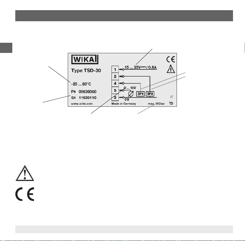
2.4 Labelling / Safety marks
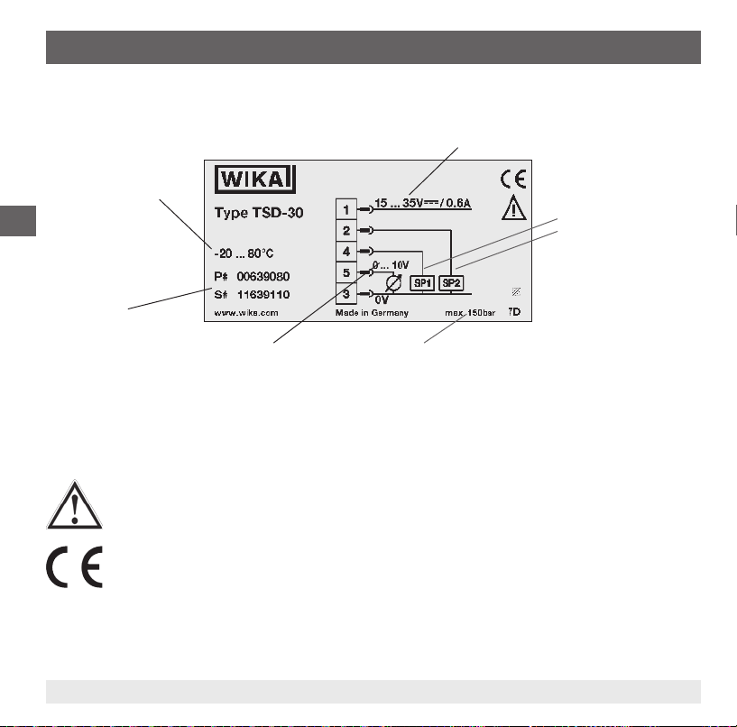
Product label
GB
Measuring range
P# Product No.
S# Serial No.
Power supply
Switching output 1
Switching output 2
Analogue signal
Maximum working pressure
If the serial number becomes illegible (e.g. due to mechanical damage or overpainting), traceability will
no longer be possible.
Explanation of symbols
General danger symbol
CE, Communauté Européenne
Instruments bearing this mark comply with the relevant European directives.
8 WIKA operating instructions temperature switch model TSD-30
11613025.02 12/2011 GB/D/F/E
Page 9

3. Specications
3. Specications
3.1 Measuring ranges
Temperature Standard Option
°C -20 ... +80 -20 ... +120
°F -4 ... +176 -4 ... +248
1) see “Operating conditions”
3.2 Display
14-segment LED, red, 4-digit, character size 9 mm
Display can be turned electronically through 180°
Update
200 ms
3.3 Output signal
Switching output 1 Switching output 2 Analogue signal
PNP - 4 ... 20 mA
PNP - DC 0 ... 10 V
PNP PNP PNP PNP 4 ... 20 mA
PNP PNP DC 0 ... 10 V
Alternatively also available with NPN rather than PNP switching output
Temperature oset adjustment
± 3 % of span
Scale setting
Zero point: max. +25 % of span
Final value: max. -25 % of span
11613025.02 12/2011 GB/D/F/E
1)
GB
9WIKA operating instructions temperature switch model TSD-30
Page 10
3. Specications
Analogue signal
Load
■
Current: ≤ 500 Ω
■
GB
Voltage: > 10 kΩ
Switching output
Switching output 1 and 2 are individually adjustable
Function
■
Normally open/closed: freely adjustable
■
Window and hysteresis: freely adjustable
Switching voltage: Power supply – 1 V
Switching current: max. 250 mA per switching output
Response time ≤ 200 ms
Adjustment accuracy:
≤ 0.5 % of span
3.4 Power supply
Power supply
DC 15 ... 35 V
Current consumption
max. 100 mA
Total current consumption
max. 600 mA (incl. switching current)
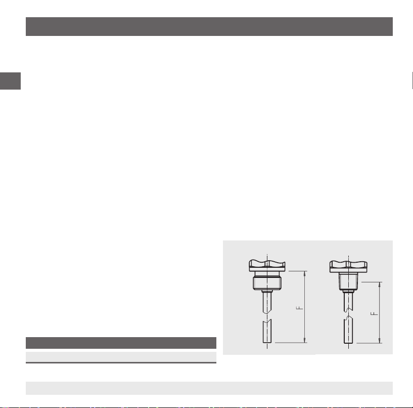
3.5 Measuring element
Pt1000, 2-wire, DIN EN 60751 / class A
Insertion length (F)
F in mm
25 50 100 150 250 350
Parallel thread Tapered thread
Fig. Insertion length (F)
10 WIKA operating instructions temperature switch model TSD-30
11613025.02 12/2011 GB/D/F/E
Page 11

3. Specications
Response time
T05 < 5 s (per DIN EN 60751)
T09 < 10 s (per DIN EN 60751)
Maximum working pressure
150 bar
3.5 Accuracy
Analogue signal
≤ ± 0,5 % of span
Switching output
≤ ± 0.8 % of span
Display
≤ ± 0.8 % of span ± 1 digit
Temperature sensor
± (0.15 K + 0.002 | t |)
| t | is the value of the temperature in °C without consideration of the sign.
The actually achievable accuracy is signicantly determined by the mounting situation (immersion
depth, sensor length, operating conditions). This is especially the case for large temperature gradients
between the environment and the medium.
3.6 Reference conditions
Temperature: 15 ... 25 °C
Atmospheric pressure: 950 ... 1,050 mbar
Humidity: 45 ... 75 % relative
Nominal position: Process connection lower mount
Power supply: DC 24 V
Load: see "Output signal"
GB
11613025.02 12/2011 GB/D/F/E
11WIKA operating instructions temperature switch model TSD-30
Page 12

3. Specications
3.7 Operating conditions
Temperatures and humidity
Medium temperature: -20 ... +80 °C
GB
Ambient temperature: -20 ... +80 °C
Storage temperature: -20 ... +80 °C
Permissible humidity: 45 ... 75 % relative
Installation instructions
Mounting position: as required
At high medium or ambient temperatures, ensure by suitable measures that the instrument case temperature does not exceed 80 °C in continuous operation (the temperature is measured at the hexagon of
the process connection).
At temperatures above 80 °C the thread must not be immersed into the medium.
3.8 Materials
Wetted parts
Temperature sensor: Stainless steel 316Ti
Non-wetted parts
Case: Stainless steel 304
Keyboard TPE-E
Display window: PC
Display head: PC + ABS-Blend
3.9 Approvals, directives and certicates
CE conformity
EMC directive: 2004/108/EC, EN 61326-2-3 emission (group 1, class B)
RoHS conformity: Yes
12 WIKA operating instructions temperature switch model TSD-30
and interference immunity (industrial application)
11613025.02 12/2011 GB/D/F/E
Page 13

3. Specications / 4. Design and function
3.10 Electrical connections
Connections
Circular connector M12 x 1, 4-pin
Circular connector M12 x 1, 5-pin
1) Only for version with two switching outputs and analogue signal
Ingress protection
IP 65 and IP 67
The stated ingress protection (per IEC 60529) only applies when plugged in using mating connectors that have the appropriate ingress
protection.
Electrical safety
Short-circuit resistance: S
Reverse polarity protection: U
Insulation voltage: DC 500 V
Overvoltage protection: DC 40 V
For further specications see WIKA data sheet TE 67.03 and the order documentation.
4. Design and function
4.1 Description
By means of a measuring element (Pt1000) and by supplying power, the prevailing temperature is
converted into a switching signal or an amplied standardised electrical signal via the change in
resistance of the measuring element. This electrical signal varies in proportion to the temperature and
can be evaluated accordingly.
1)
/ SP1 / SP2 vs. U
+
vs. U
+
-
-
GB
4.2 Scope of delivery
Cross-check scope of delivery with the delivery note.
11613025.02 12/2011 GB/D/F/E
13WIKA operating instructions temperature switch model TSD-30
Page 14
5. Transport, packaging and storage / 6. Commissioning, ...
5. Transport, packaging and storage
5.1 Transport
Check the temperature switch for any damage that may have been caused by transport.
GB
Obvious damage must be reported immediately.
5.2 Packaging
Do not remove packaging until just before mounting.
Keep the packaging as it will provide optimum protection during transport (e.g. change in installation site,
sending for repair).
5.3 Storage
Permissible conditions at the place of storage:
■
Storage temperature: -20 ... +80 °C
■
Humidity: 45 ... 75 % relative humidity
WARNING!
Before storing the instrument (following operation), remove any residual media. This is of
particular importance if the medium is hazardous to health, e.g. caustic, toxic, carcinogenic,
radioactive, etc.
6. Commissioning, operation
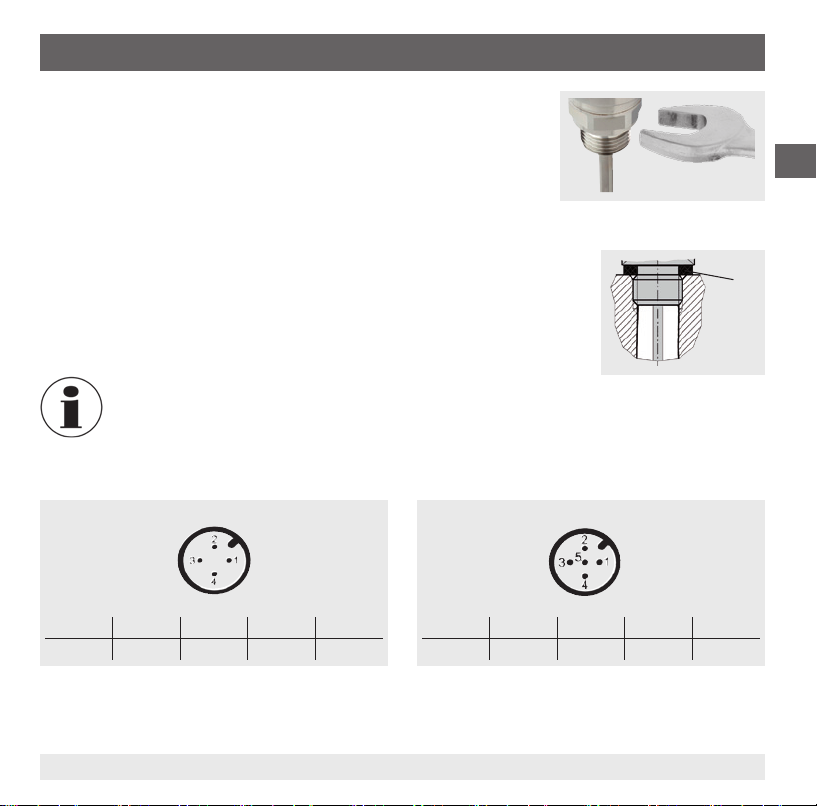
6.1 Mounting
Required tool: Open-ended spanner (spanner width 27)
■
The sealing faces at the temperature switch and the measuring point always have to be clean.
■
Only ever screw in, or unscrew, the instrument via the spanner ats. Never use the case as a working
surface.
14 WIKA operating instructions temperature switch model TSD-30
11613025.02 12/2011 GB/D/F/E
Page 15
6. Commissioning, operation
■
The correct torque depends on the dimensions of the process
connection and the sealing used (form/material).
■
When screwing in, do not cross the threads.
■
For information on tapped holes and welding sockets, see Technical
Information IN 00.14 at www.wika.com.
■
The instrument must be earthed via the process connection.
■
Attach the connector and screw it in hand-tight.
Seal
Correct sealing of the process connections with parallel threads at the sealing
face
must be made using suitable at gaskets, sealing rings or WIKA prole
sealings. The sealing of tapered threads (e.g. NPT threads) is made by providing the thread with additional sealing material such as, for example, PTFE tape
(EN 837-2).
For further information on sealings see WIKA data sheet AC 09.08 or under www.wika.com.
Connection diagrams
Circular connector M12 x 1, 4-pin
Circular connector M12 x 1, 5-pin
GB
Assignment
U+ U- S+ SP1 SP2
1 3 2 4 2
11613025.02 12/2011 GB/D/F/E
Assignment
U+ U- S+ SP1 SP2
1 3 5 4 2
15WIKA operating instructions temperature switch model TSD-30
Page 16
6. Commissioning, operation
6.2 Operating modes
System start
■
GB
Display is fully activated for 2 seconds.
■
When the temperature switch is powered up within the range of the hysteresis, the output switch is set
to "not active" by default.
Display mode
Normal operation, display temperature value
Programming mode
Setting the parameters
6.3 Keys and functions
The temperature switch has two operating modes, the display mode and the programming mode. The
selected operating mode determines the respective function of the key.
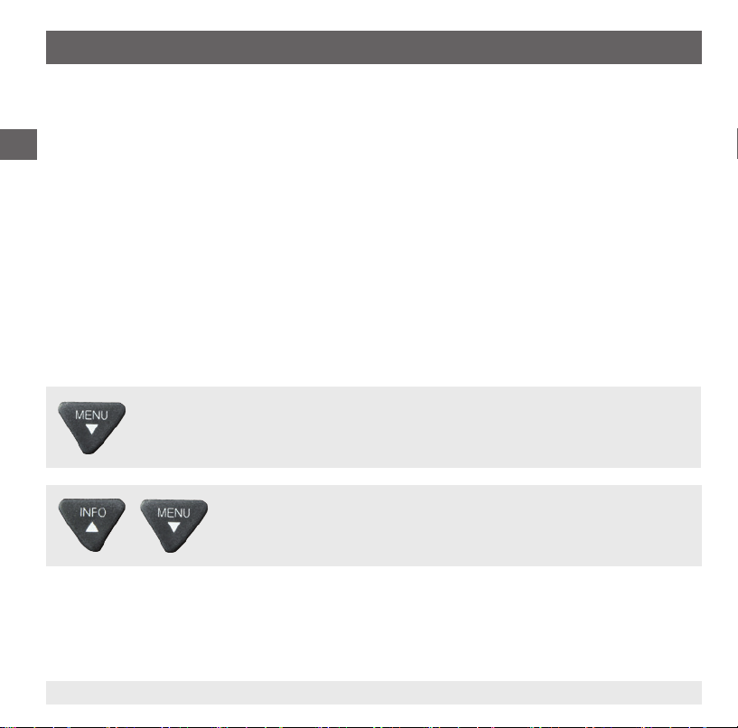
Jumping to the programming mode
Keep the "MENU" key pressed for approx. 5 seconds. If the password is set to ≠
a password will be requested rst-hand.
programming mode, otherwise it reverts to display mode.
Returning to the display mode
Simultaneous pressing of both keys.
If authentication is successful, then it enters the
0000
,
16 WIKA operating instructions temperature switch model TSD-30
11613025.02 12/2011 GB/D/F/E
Page 17
6. Commissioning, operation
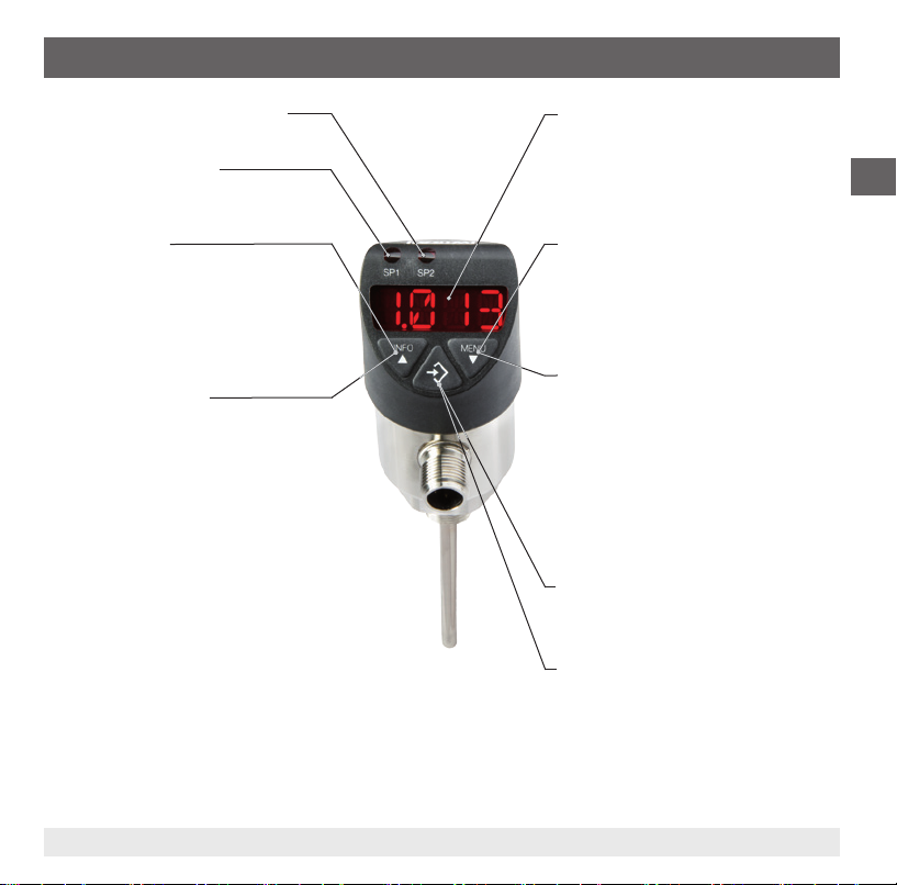
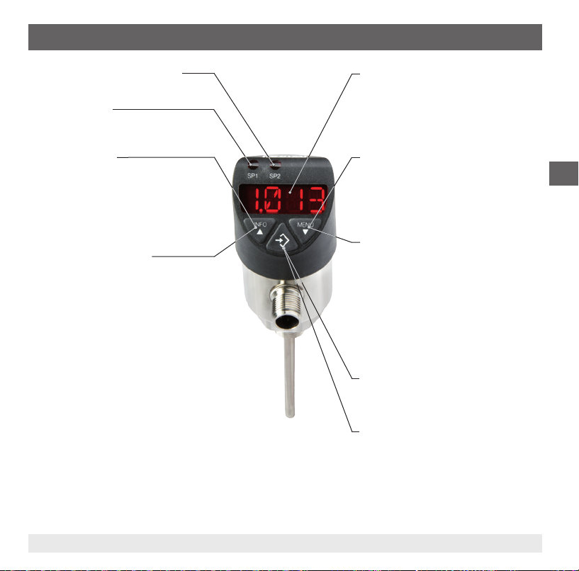
Status switching output 2 (optional)
Status switching output 1
Display mode
▶ Short press
Display of the unit
▶ Long press
Display of the set parameters see
chapter 6.4 “Parameters"
Programming mode
▶ Short press
Menu up
Parameter value up (step-wise)
▶ Long press
Menu up
Parameter value up (fast)
4-digit LED display
■
Display temperature value
■
Display menu item
■
Display parameter
Display mode
▶ Short press
Display of the unit
▶ Long press
Jumping into the programming mode
Programming mode
▶ Short press
Menu up
Parameter value up (step-wise)
▶ Long press
Menu up
Parameter value up (fast)
Display mode
▶ Short press
Display of the unit
Programming mode
▶ Short press
Select menu item
Conrmation of the input
GB
11613025.02 12/2011 GB/D/F/E
17WIKA operating instructions temperature switch model TSD-30
Page 18

6. Commissioning, operation
6.4 Parameters
Parameter Description
SP1/SP2 Hysteresis function: Switch point switching output (1 or 2)
GB
FH1/FH2 Window function: Window high switching output (1 or 2)
RP1/RP2 Hysteresis function: Reset point switching output (1 or 2)
FL1/FL2 Window function: Window low switch output (1 or 2)
EF Extended programming functions
RES Return the set parameter to the factory settings
DS1/DS2 Switch delay time, which must occur without interruption before any electrical signal change occurs
DR1/DR2 Switch delay time, which must occur without interruption before any electrical signal change occurs
OU1 Switching function switching output (1 or 2)
OU2 HNO = hysteresis function, normally open
UNIT Changing units
SETR
OFS Oset adjustment (3 % of span)
DISM Display value in display mode
DISR Rotate display indicator by 180°
RHL Clear the Min- and Max-value memories
PAS Password input, 0000 = no password; Password input digit by digit
TAG Input of a 16-gure alphanumeric measuring point number
18 WIKA operating instructions temperature switch model TSD-30
(SP1 or SP2)
(RP1 or RP2)
HNC = hysteresis function, normally closed
FNO = window function, normally open
FNC = window function, normally closed
(If the measuring range is outside the indication range, a unit switching is not possible and the UNIT
parameter is not indicated)
Measuring range scaling (analogue output)
“4 mA” or “0 V” determines at which temperature the output signal is to be 4 mA or 0 V.
“20 mA” or “10 V” determines at which temperature the output signal is to be 20 mA or 10 V.
ACT = Actual temperature value; LOW, HIGH = Minimum, Maximum temperature value
OFF = display o;
SP1/FH1 = function switch point 1, RP1/FL1 = function reset point 1,
SP2/FH2 = function switch point 2, RP2/FL2 = function reset point 2
11613025.02 12/2011 GB/D/F/E
Page 19
6. Commissioning, operation
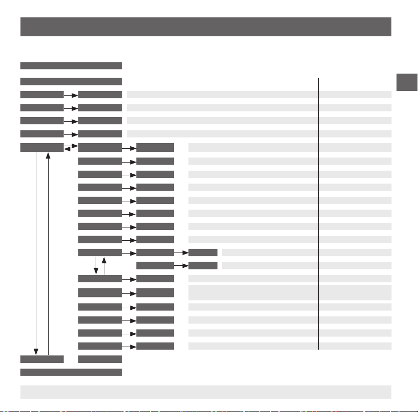
Menu (programming and factory setting)
Display mode
Long pressing of the "MENU" key
▲ ▼
Programming mode
▲ ▼
SP1 / FH1
▲ ▼
RP1 / FL1
▲ ▼
SP2 / FH2
▲ ▼
RP2 / FL2
▲ ▼
EF RES
END END
▼ ▼ ▼ ▼
Display mode
11613025.02 12/2011 GB/D/F/E
Value
Value
Value
Value
▲ ▼
DS1
▲ ▼
DR1
▲ ▼
DS2
▲ ▼
DR2
▲ ▼
OU1
▲ ▼
OU2
▲ ▼
UNIT
▲ ▼
SETR
OFS
▲ ▼
▲ ▼
DISR
▲ ▼
RHL
▲ ▼
PAS
▲ ▼
TAG
▲ ▼
Min: MBA + 0.5 %, Max: MBE MBE
Min: MBA, Max: SP1 - 0.5 % MBE -10 %
Min: MBA + 0.5 %, Max: MBE MBE
Min: MBA, Max: SP2 - 0.5 % MBE -10%
Yes / No
Value
Value
Value
Value
PARA
PARA
Unit
4 mA / 0V Value
▲ ▼
20 mA / 10V Value
Yes / No
PARA
Yes / No
Yes / No
Value
Value
Legend:
MBA = Start of measuring range
MBE = End of measuring range
Factory setting:
Reset to factory setting
0 ... 50 s 0 s
0 ... 50 s 0 s
0 ... 50 s 0 s
0 ... 50 s 0 s
HNO, HNC, FNO, FNC HNO
HNO, HNC, FNO, FNC HNO
°C, °F Order-related
MBA - 25 % of span
MBE + 25 % of span
Oset setting 3 % of span
ACT, HIGH, LOW, OFF, SP1/FH1, RP1/FL1,
SP2/FH2, RP2/FL2
Rotate display indicator by 180°
Reset HIGH, LOW
Password without
Measuring point number without
MBA
MBE
0 s
ACTDISM
GB
19WIKA operating instructions temperature switch model TSD-30
Page 20
6. Commissioning, operation
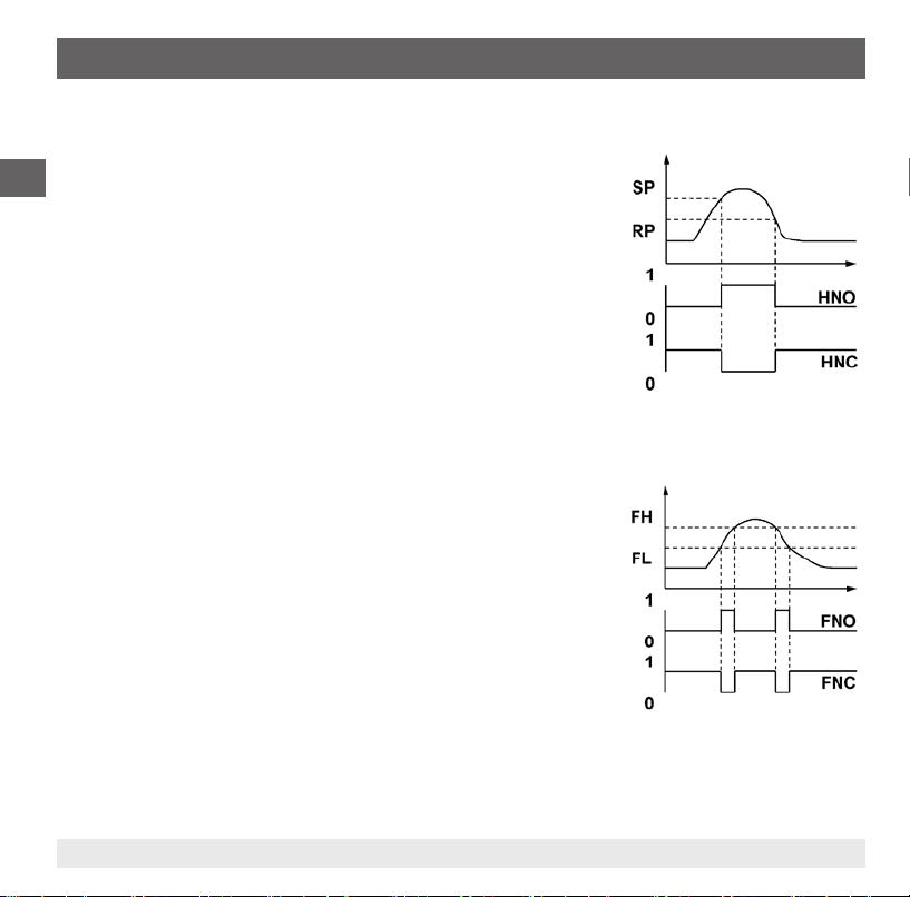
6.4 Switching functions
Hysteresis function
If the temperature uctuates around the set point, the hysteresis keeps
GB
the switching status of the outputs stable. With increasing temperature,
the output switches when reaching the switch point (SP).
■
Contact normally open (HNO): active
■
Contact normally closed (HNC): inactive
With temperature falling again, the output will not switch back before
the reset point (RP) is reached.
■
Contact normally open (HNO): inactive
■
Contact normally closed (HNC): active
Window function
The window function allows for the control of a dened range.
When the temperature is between window High (FH) and window Low
(FL), the output switches on.
■
Contact normally open (FNO): active
■
Contact normally closed (FNC): inactive
When the temperature is outside window High (FH) and window Low
(FL), the output does not switch on.
Fig.: Hysteresis function
■
Contact normally open (FNO): inactive
■
Contact normally closed (FNC): active
Fig.: Window function
20 WIKA operating instructions temperature switch model TSD-30
11613025.02 12/2011 GB/D/F/E
Page 21
6. Commissioning, operation
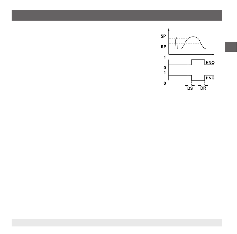
Delay times (0 ... 50 s)
This makes it possible to lter out unwanted temperature peaks of a
short duration or a high frequency (damping).
The temperature must be present for at least a certain pre-set time for
the output to switch on. The output does not immediately change its
status when it reaches the switching event (SP), but rather only after
the pre-set delay time (DS).
If the switching event is no longer present after the delay time, the
switch output does not change.
The output only switches back when the temperature has fallen down
to the reset point (PR) and stays at or below the reset point (RP) for at
least the pre-set delay time (DR).
If the switching event is no longer present after the delay time, the
switch output does not change.
GB
Fig.: Delay times
11613025.02 12/2011 GB/D/F/E
21WIKA operating instructions temperature switch model TSD-30
Page 22
7. Maintenance and cleaning / 8. Faults
7. Maintenance and cleaning
7.1 Maintenance
The temperature switch is maintenance-free.
GB
Repairs must only be carried out by the manufacturer.
7.2 Cleaning
CAUTION!
■
Clean the instrument with a moist cloth.
■
Electrical connections must not come into contact with moisture.
■
Wash or clean the dismounted instrument before returning it in order to protect personnel
and the environment from exposure to residual media.
■
Residual media in the dismounted temperature switch can result in a risk to persons, the
environment and equipment. Take sucient precautionary measures.
For information on returning the instrument see chapter 9.2 "Return".
8. Faults
In the event of any faults, rst check whether the temperature switch is mounted correctly, mechanically
and electrically.
Error display
Via the instrument's display internal errors are output.
The following table shows the error codes and their meaning.
22 WIKA operating instructions temperature switch model TSD-30
11613025.02 12/2011 GB/D/F/E
Page 23

8. Faults
Error code Description
ATT1 On changing the switch point, the system automatically reduces the reset point
ATT3 Password entered for menu access is incorrect
ERR Internal error
OL Measuring range exceeded > approx. 5 % (display blinks)
UL Below measuring range < approx. 5 % (display blinks)
Acknowledgement of an error display by pressing the "Enter" key.
Problem Possible cause Measure
No output signal Cable break Check the through drilling
No output signal / line break Mechanical load too high Replace sensor with a suitable design
No output signal No/wrong power supply Rectify the power supply
No/wrong output signal Wiring error Observe the pin assignment
Wrong output signal Process temperature out of range;
Wrong output signal Sensor drift caused by chemical attack Check media compatibility
Wrong output signal and too long
response time
Signal span too small Power supply too high/low Rectify the power supply
Signal span drops Humidity has entered Assemble the cable correctly
If complaint is unjustied, we will charge you the complaint processing fees.
Sensor drift caused by overtemperature
Sensor burnout/short circuit
Wrong mounting geometry, for example
mounting depth too deep or heat dissipation too high
Deposit on the sensor
Check temperature range
Send the instrument to the manufacturer
Move the temperature-sensitive area
of the sensor into the medium
Remove deposit
GB
11613025.02 12/2011 GB/D/F/E
23WIKA operating instructions temperature switch model TSD-30
Page 24
8. Faults / 9. Dismounting, return and disposal
CAUTION!
If faults cannot be eliminated by means of the measures listed above, the temperature
switch must be shut down immediately, and it must be ensured that signal is no longer
GB
9. Dismounting, return and disposal
9.1 Dismounting
9.2 Return
present, and it must be prevented from being inadvertently put back into service. In this
case, contact the manufacturer. If a return is needed, follow the instructions given in chapter
9.2 "Return".
WARNING!
Residual media in the dismounted temperature switch can result in a risk to persons, the
environment and equipment.
Take sucient precautionary measures.
WARNING!
Risk of burns!
Let the instrument cool down suciently before dismounting it!
During dismounting there is a risk of dangerously hot pressure media escaping.
WARNING!
Strictly observe the following when shipping the instrument:
All instruments delivered to WIKA must be free from any kind of hazardous substances
(acids, leachate, solutions, etc.).
When returning the instrument, use the original packaging or a suitable transport package.
24 WIKA operating instructions temperature switch model TSD-30
11613025.02 12/2011 GB/D/F/E
Page 25

9. Dismounting, return and disposal
Enclose the completed return form with the instrument.
The return form can be found under the heading 'Service' at www.wika.com.
9.3 Disposal
Incorrect disposal can put the environment at risk.
Dispose of instrument components and packaging materials in an environmentally compatible way and
in accordance with the country-specic waste disposal regulations.
GB
11613025.02 12/2011 GB/D/F/E
25WIKA operating instructions temperature switch model TSD-30
Page 26
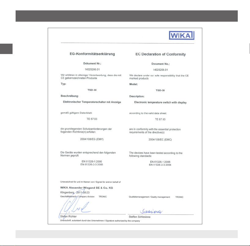
Appendix 1: EC Declaration of Conformity for model TSD-30
GB
26 WIKA operating instructions temperature switch model TSD-30
11613025.02 12/2011 GB/D/F/E
Page 27
Inhalt
Inhalt
1. Allgemeines 28
2. Sicherheit 30
3. Technische Daten 33
4. Aufbau und Funktion 37
5. Transport, Verpackung und Lagerung 38
6. Inbetriebnahme, Betrieb 38
7. Wartung und Reinigung 46
8. Störungen 46
9. Demontage, Rücksendung und Entsorgung 48
10. Anlage 1: EG-Konformitätserklärung Typ TSD-30 50
Konformitätserklärungen nden Sie online unter www.wika.de.
11613025.02 12/2011 GB/D/F/E
D
27WIKA Betriebsanleitung Temperaturschalter Typ TSD-30
Page 28

1. Allgemeines
1. Allgemeines
■
Der in der Betriebsanleitung beschriebene Temperaturschalter wird nach den neuesten Erkenntnissen konstruiert und gefertigt.
Alle Komponenten unterliegen während der Fertigung strengen Qualitäts- und Umweltkriterien.
Unsere Managementsysteme sind nach ISO 9001 und ISO 14001 zertiziert.
D
■
Diese Betriebsanleitung gibt wichtige Hinweise zum Umgang mit dem Gerät. Voraussetzung für
sicheres Arbeiten ist die Einhaltung aller angegebenen Sicherheitshinweise und Handlungsanweisungen.
■
Die für den Einsatzbereich des Gerätes geltenden örtlichen Unfallverhütungsvorschriften und allgemeinen Sicherheitsbestimmungen einhalten.
■
Die Betriebsanleitung ist Produktbestandteil und muss in unmittelbarer Nähe des Gerätes für das
Fachpersonal jederzeit zugänglich aufbewahrt werden.
■
Das Fachpersonal muss die Betriebsanleitung vor Beginn aller Arbeiten sorgfältig durchgelesen und
verstanden haben.
■
Die Haftung des Herstellers erlischt bei Schäden durch bestimmungswidrige Verwendung, Nichtbeachten dieser Betriebsanleitung, Einsatz ungenügend qualizierten Fachpersonals sowie eigenmächtiger Veränderung am Gerät.
■
Es gelten die allgemeinen Geschäftsbedingungen in den Verkaufsunterlagen.
■
Technische Änderungen vorbehalten.
■
Weitere Informationen:
- Internet-Adresse: www.wika.de / www.wika.com
- zugehöriges Datenblatt: TE 67.03
- Anwendungsberater:
Tel.: (+49) 9372/132-8976
Fax: (+49) 9372/132-8008976
E-Mail: support-tronic@wika.de
28 WIKA Betriebsanleitung Temperaturschalter Typ TSD-30
11613025.02 12/2011 GB/D/F/E
Page 29
1. Allgemeines
Symbolerklärung
WARNUNG!
… weist auf eine möglicherweise gefährliche Situation hin, die zum Tod oder zu schweren
Verletzungen führen kann, wenn sie nicht gemieden wird.
VORSICHT!
… weist auf eine möglicherweise gefährliche Situation hin, die zu geringfügigen oder
leichten Verletzungen bzw. Sach- und Umweltschäden führen kann, wenn sie nicht
gemieden wird.
Information
… hebt nützliche Tipps und Empfehlungen sowie Informationen für einen ezienten und
störungsfreien Betrieb hervor.
VORSICHT!
… weist auf eine möglicherweise gefährliche Situation hin, die durch heiße Oberächen
oder Flüssigkeiten zu Verbrennungen führen kann, wenn sie nicht gemieden wird.
Abkürzungen
U
+
U
-
S
+
SP1 Schaltpunkt 1
SP2 Schaltpunkt 2
MBA Messbereichsanfang
MBE Messbereichsende
Positiver Versorgungsanschluss
Bezugspotential
Analogausgang
D
11613025.02 12/2011 GB/D/F/E
29WIKA Betriebsanleitung Temperaturschalter Typ TSD-30
Page 30

2. Sicherheit
2. Sicherheit
WARNUNG!
Vor Montage, Inbetriebnahme und Betrieb sicherstellen, dass der richtige Temperaturschalter
hinsichtlich Messbereich, Ausführung und spezischen Messbedingungen ausgewählt
D
2.1 Bestimmungsgemäße Verwendung
Der Temperaturschalter dient zum Umwandeln von Temperatur in ein elektrisches Signal im Innen- und
Außenbereich.
Das Gerät ist ausschließlich für den hier beschriebenen bestimmungsgemäßen Verwendungszweck
konzipiert und konstruiert und darf nur dementsprechend verwendet werden.
Die technischen Spezikationen in dieser Betriebsanleitung sind einzuhalten. Eine unsachgemäße
Handhabung oder ein Betreiben des Temperaturschalters außerhalb der technischen Spezikationen
macht die sofortige Stilllegung und Überprüfung durch einen autorisierten WIKA-Servicemitarbeiter
erforderlich.
wurde.
Bei Nichtbeachten können schwere Körperverletzungen und/oder Sachschäden auftreten.
WARNUNG!
Betriebsparameter gemäß Kapitel 3 „Technische Daten“ beachten.
Weitere wichtige Sicherheitshinweise benden sich in den einzelnen Kapiteln dieser
Betriebsanleitung.
Ansprüche jeglicher Art aufgrund von nicht bestimmungsgemäßer Verwendung sind ausgeschlossen.
30 WIKA Betriebsanleitung Temperaturschalter Typ TSD-30
11613025.02 12/2011 GB/D/F/E
Page 31

2. Sicherheit
2.2 Personalqualikation
WARNUNG!
Verletzungsgefahr bei unzureichender Qualikation!
Unsachgemäßer Umgang kann zu erheblichen Personen- und Sachschäden führen.
Die in dieser Betriebsanleitung beschriebenen Tätigkeiten nur durch Fachpersonal nachfolgend beschriebener Qualikation durchführen lassen.
Fachpersonal
Das Fachpersonal ist aufgrund seiner fachlichen Ausbildung, seiner Kenntnisse der Mess- und
Regelungstechnik und seiner Erfahrungen sowie Kenntnis der landesspezischen Vorschriften,
geltenden Normen und Richtlinien in der Lage, die beschriebenen Arbeiten auszuführen und mögliche
Gefahren selbstständig zu erkennen.
Spezielle Einsatzbedingungen verlangen weiteres entsprechendes Wissen, z. B. über aggressive Medien.
2.3 Besondere Gefahren
WARNUNG!
Bei gefährlichen Messstoen wie z. B. Sauersto, Acetylen, brennbaren oder giftigen
Stoen, sowie bei Kälteanlagen, Kompressoren etc. müssen über die gesamten allgemeinen
Regeln hinaus die einschlägigen Vorschriften beachtet werden.
WARNUNG!
Messstoreste im ausgebauten Temperaturschalter können zur Gefährdung von Personen,
Umwelt und Einrichtung führen.
Ausreichende Vorsichtsmaßnahmen ergreifen.
D
11613025.02 12/2011 GB/D/F/E
31WIKA Betriebsanleitung Temperaturschalter Typ TSD-30
Page 32

2. Sicherheit
2.4 Beschilderung / Sicherheitskennzeichnungen
Typenschild
D
Messbereich
P# Erzeugnis-Nr.
S# Serien-Nr.
Hilfsenergie
Schaltausgang 1
Schaltausgangt 2
Analogsignal
Maximaler Betriebsdruck
Wird die Seriennummer unleserlich (z. B. durch mechanische Beschädigung oder Übermalen), ist eine
Rückverfolgbarkeit nicht mehr möglich.
Symbolerklärung
Allgemeines Gefahrensymbol
CE, Communauté Européenne
Geräte mit dieser Kennzeichnung stimmen überein mit den zutreenden europäischen
Richtlinien.
32 WIKA Betriebsanleitung Temperaturschalter Typ TSD-30
11613025.02 12/2011 GB/D/F/E
Page 33

3. Technische Daten
3. Technische Daten
3.1 Messbereiche
Temperatur Standard Option
°C -20 ... +80 -20 ... +120
°F -4 ... +176 -4 ... +248
1) siehe „Einsatzbedingungen“
3.2 Display
14-Segment-LED, rot, 4-stellig, Ziernhöhe 9 mm
Darstellung ist elektronisch um 180° drehbar
Aktualisierung
200 ms
3.3 Ausgangssignal
Schaltausgang 1 Schaltausgang 2 Analogsignal
PNP - 4 ... 20 mA
PNP - DC 0 ... 10 V
PNP PNP PNP PNP 4 ... 20 mA
PNP PNP DC 0 ... 10 V
Alternativ auch mit NPN anstatt PNP Schaltausgang erhältlich
Abgleich Temperaturoset
± 3 % der Spanne
Skalierung
Nullpunkt: max. +25 % der Spanne
Endwert: max. -25 % der Spanne
11613025.02 12/2011 GB/D/F/E
1)
D
33WIKA Betriebsanleitung Temperaturschalter Typ TSD-30
Page 34

3. Technische Daten
Analogsignal
Bürde
■
Strom: ≤ 500 Ω
■
Spannung: > 10 kΩ
Schaltausgang
D
Schaltpunkt 1 und 2 sind individuell einstellbar
Funktion
■
Schließer/Öner: frei einstellbar
■
Fenster und Hysterese: frei einstellbar
Schaltspannung: Hilfsenergie – 1 V
Schaltstrom: max. 250 mA pro Schaltausgang
Einstellzeit: ≤ 200 ms
Einstellgenauigkeit:
3.4 Spannungsversorgung
Hilfsenergie
DC 15 ... 35 V
Stromverbrauch
max. 100 mA
Gesamtstromaufnahme
max. 600 mA (inkl. Schaltstrom)
3.5 Messelement
Pt1000, 2-Leiter, DIN EN 60751 / Klasse A
Einbaulänge (F)
F in mm
25 50 100 150 250 350
≤ 0,5 % der Spanne
Zylindrisches Gewinde Kegeliges Gewinde
Abb. Einbaulänge (F)
34 WIKA Betriebsanleitung Temperaturschalter Typ TSD-30
11613025.02 12/2011 GB/D/F/E
Page 35

3. Technische Daten
Ansprechzeit
T05 < 5 s (nach DIN EN 60751)
T09 < 10 s (nach DIN EN 60751)
Maximaler Betriebsdruck
150 bar
3.5 Genauigkeit
Analogsignal
≤. ± 0,5 % der Spanne
Schaltausgang
≤ ± 0,8 % der Spanne
Anzeige
≤ ± 0,8 % der Spanne ± 1 Digit
Temperatursensor
± (0,15 K + 0,002 |t|)
| t | ist der Zahlenwert der Temperatur in °C ohne Berücksichtigung des Vorzeichens.
Die tatsächlich erzielbare Genauigkeit wird maßgeblich durch die Einbausituation (Eintauchtiefe,
Fühlerlänge, Einsatzbedingungen) mitbestimmt. Dies gilt besonders bei großen Temperaturgradienten
zwischen Umgebung und Medium.
3.6 Referenzbedingungen
Temperatur: 15 ... 25 °C
Luftdruck: 950 ... 1.050 mbar
Luftfeuchte: 45 ... 75 % relativ
Nennlage: Prozessanschluss unten
Hilfsenergie: DC 24 V
Bürde: siehe „Ausgangssignal“
11613025.02 12/2011 GB/D/F/E
D
35WIKA Betriebsanleitung Temperaturschalter Typ TSD-30
Page 36

3. Technische Daten
3.7 Einsatzbedingungen
Temperaturen und Luftfeuchte
Medientemperatur: -20 ... +80 °C
Umgebungstemperatur: -20 ... +80 °C
Lagertemperatur: -20 ... +80 °C
D
Zulässige Luftfeuchtigkeit: 45 ... 75 % relativ
Einbauhinweis
Einbaulage: beliebig
Bei hohen Medien- oder Umgebungstemperaturen ist durch geeignete Maßnahmen sicherzustellen,
dass die Gehäusetemperatur des Gerätes im Dauerbetrieb 80 °C nicht überschreitet (Temperatur wird
am Sechskant des Prozessanschlusses gemessen).
Bei Temperaturen über 80 °C darf das Gewinde nicht in das Medium eintauchen.
3.8 Werkstoe
Messstoberührte Teile
Temperaturfühler: CrNi-Stahl 316Ti
Nicht messstoberührte Teile
Gehäuse: CrNi-Stahl 304
Tastatur: TPE-E
Displayscheibe: PC
Anzeigekopf: PC + ABS-Blend
3.9 Zulassungen, Richtlinien und Zertikate
CE-Konformität
EMV-Richtlinie: 2004/108/EG, EN 61326-2-3 Emission (Gruppe1, Klasse B) Störfestigkeit
RoHS-Konformität: Ja
(industrieller Bereich)
36 WIKA Betriebsanleitung Temperaturschalter Typ TSD-30
11613025.02 12/2011 GB/D/F/E
Page 37

3. Technische Daten / 4. Aufbau und Funktion
3.10 Elektrische Anschlüsse
Anschlüsse
Rundstecker M12 x 1, 4-polig
Rundstecker M12 x 1, 5-polig
1) Nur bei Ausführung mit zwei Schaltausgängen und Analogsignal
Schutzart
IP 65 und IP 67
Die angegebenen Schutzarten (nach IEC 60529) gelten nur im gesteckten Zustand mit Gegensteckern entsprechender Schutzart.
Elektrische Sicherheit
Kurzschlussfestigkeit: S+ / SP1 / SP2 gegen U
Verpolschutz: U+ gegen U
Isolationsspannung: DC 500 V
Überspannungsschutz: DC 40 V
Weitere Technische Daten siehe WIKA Datenblatt TE 67.03 und Bestellunterlagen.
4. Aufbau und Funktion
4.1 Beschreibung
Mittels Messelement (Pt1000) und unter Zuführung von Hilfsenergie wird über die
Widerstandsänderung des Messelements die anstehende Temperatur in ein Schaltsignal, bzw.
verstärktes standardisiertes elektrisches Signal umgewandelt. Dieses elektrische Signal verändert sich
proportional zur Temperatur und kann entsprechend ausgewertet werden.
1)
-
-
D
4.2 Lieferumfang
Lieferumfang mit dem Lieferschein abgleichen.
11613025.02 12/2011 GB/D/F/E
37WIKA Betriebsanleitung Temperaturschalter Typ TSD-30
Page 38
5. Transport, Verpackung und Lagerung / 6. Inbetriebnahme, ...
5. Transport, Verpackung und Lagerung
5.1 Transport
Temperaturschalter auf eventuell vorhandene Transportschäden untersuchen.
Oensichtliche Schäden unverzüglich mitteilen.
D
5.2 Verpackung
Verpackung erst unmittelbar vor der Montage entfernen.
Die Verpackung aufbewahren, denn diese bietet bei einem Transport einen optimalen Schutz
(z. B. wechselnder Einbauort, Reparatursendung).
5.3 Lagerung
Zulässige Bedingungen am Lagerort:
■
Lagertemperatur: -20 ... +80 °C
■
Feuchtigkeit: 45 ... 75 % relative Feuchte
WARNUNG!
Vor der Einlagerung des Gerätes (nach Betrieb) alle anhaftenden Messstoreste entfernen.
Dies ist besonders wichtig, wenn der Messsto gesundheitsgefährdend ist, wie z. B. ätzend,
giftig, krebserregend, radioaktiv, usw.
6. Inbetriebnahme, Betrieb
6.1 Montage
Benötigtes Werkzeug: Maulschlüssel (Schlüsselweite 27)
■
Dichtächen am Temperaturschalter und der Messstelle müssen stets frei von Verschmutzungen sein.
■
Das Gerät nur über die Schlüsselächen ein- bzw. ausschrauben. Niemals das Gehäuse als Angrisäche verwenden.
38 WIKA Betriebsanleitung Temperaturschalter Typ TSD-30
11613025.02 12/2011 GB/D/F/E
Page 39

6. Inbetriebnahme, Betrieb
■
Das richtige Drehmoment ist abhängig von der Dimension des
Prozessanschlusses sowie der verwendeten Dichtung (Form/
Werksto).
■
Beim Einschrauben die Gewindegänge nicht verkanten.
■
Angaben zu Einschraublöchern und Einschweißstutzen siehe
Technische Information IN 00.14 unter www.wika.de.
■
Das Gerät über den Prozessanschluss erden.
■
Stecker aufstecken und handfest verschrauben.
D
Abdichtung
Zur Abdichtung der Prozessanschlüsse mit zylindrischem Gewinde an der
Dichtäche
einzusetzen.
tung im Gewinde
sind Flachdichtungen, Dichtlinsen oder WIKA-Proldichtungen
Bei kegeligem Gewinde (z. B. NPT-Gewinde) erfolgt die Abdich-
, mit zusätzlichen Dichtwerkstoen, wie z.B. PTFE-Band
(EN 837-2).
Hinweise zu Dichtungen siehe WIKA Datenblatt AC 09.08 oder unter www.wika.de.
Anschlussschemen
Rundstecker M12 x 1, 4-polig
Belegung
+
U- S
+
U
1 3 2 4 2
11613025.02 12/2011 GB/D/F/E
SP1 SP2
Rundstecker M12 x 1, 5-polig
Belegung
+
U- S
U
1 3 5 4 2
+
SP1 SP2
39WIKA Betriebsanleitung Temperaturschalter Typ TSD-30
Page 40

6. Inbetriebnahme, Betrieb
6.2 Betriebsmodi
Systemstart
■
Display wird 2 Sekunden lang vollständig angesteuert.
■
Bei Start des Temperaturschalters im Bereich der Hysterese wird standardmäßig der Ausgangsschalter
auf „nicht-aktiv“ gesetzt.
D
Displaymodus
Normaler Arbeitsbetrieb, Anzeige Temperaturwert
Programmiermodus
Einstellen der Parameter
6.3 Tasten und Funktionen
Der Temperaturschalter verfügt über zwei Betriebsmodi, den Displaymodus und den Programmiermodus.
Der ausgewählte Betriebsmodus bestimmt die jeweilige Funktion der Taste.
Sprung in den Programmiermodus
Taste „MENU“ etwa 5 Sekunden lang betätigen. Falls Passwort ≠ 0000 gesetzt ist
erfolgt erst eine Passwortabfrage. Bei erfolgreicher Bestätigung erfolgt der
Programmiermodus, ansonsten erfolgt Rücksprung in Displaymodus.
Rücksprung in den Displaymodus
Gleichzeitige Betätigung beider Tasten.
Zugang zum
40 WIKA Betriebsanleitung Temperaturschalter Typ TSD-30
11613025.02 12/2011 GB/D/F/E
Page 41

6. Inbetriebnahme, Betrieb
Status Schaltausgang 2 (optional)
Status Schaltausgang 1
Displaymodus
▶ Kurze Betätigung
Anzeige der Einheit
▶ Lange Betätigung
Anzeige der eingestellten Parameter
siehe Kapitel 6.4 „Parameter“
Programmiermodus
▶ Kurze Betätigung
Menü aufwärts
Parameterwert aufwärts (schrittweise)
▶ Lange Betätigung
Menü aufwärts
Parameterwert aufwärts (schnell)
4-stellige LED Anzeige
■
Anzeige Temperaturwert
■
Anzeige Menüpunkt
■
Anzeige Parameter
Displaymodus
▶ Kurze Betätigung
Anzeige der Einheit
▶ Lange Betätigung
Sprung in den Programmiermodus
Programmiermodus
▶ Kurze Betätigung
Menü aufwärts
Parameterwert aufwärts (schrittweise)
▶ Lange Betätigung
Menü aufwärts
Parameterwert aufwärts (schnell)
Displaymodus
▶ Kurze Betätigung
Anzeige der Einheit
Programmiermodus
▶ Kurze Betätigung
Auswahl Menüpunkt
Bestätigung der Eingabe
D
11613025.02 12/2011 GB/D/F/E
41WIKA Betriebsanleitung Temperaturschalter Typ TSD-30
Page 42

6. Inbetriebnahme, Betrieb
6.4 Parameter
Parameter Beschreibung
SP1/SP2 Hysteresefunktion: Schaltpunkt Schaltausgang (1 ggf. 2)
FH1/FH2 Fensterfunktion: Fenster High Schaltausgang (1 ggf. 2)
RP1/RP2 Hysteresefunktion: Rückschaltpunkt Schaltausgang (1 ggf. 2)
D
FL1/FL2 Fensterfunktion: Fenster Low Schaltausgang (1 ggf. 2)
EF Erweiterte Programmier Funktionen
RES Rücksetzen der eingestellten Parameter auf die Werkseinstellungen
DS1/DS2 Schaltverzögerungszeit, die ununterbrochen anstehen muss, bis ein elektrischer Signalwechsel erfolgt (SP1
DR1/DR2 Schaltverzögerungszeit, die ununterbrochen anstehen muss, bis ein elektrischer Signalwechsel erfolgt (RP1
OU1 Schaltfunktion Schaltausgang (1 ggf. 2)
OU2 HNO = Hysteresefunktion, Schließer
UNIT Einheitenumschaltung
SETR Messbereichsskalierung (Analogausgang)
OFS Oset-Einstellung (3% der Spanne)
DISM Anzeigewert im Display-Mode
DISR Display-Anzeige 180° drehen
RHL Löschen des Min- und Maxwert Speichers
PAS Passworteingabe, 0000 = kein Passwort; Passworteingabe Digit by Digit
TAG Eingabe einer 16-stelligen alphanumerischen Messstellennummer
ggf. SP2)
ggf. RP2)
HNC = Hysteresefunktion, Öner
FNO = Fensterfunktion, Schließer
FNC = Fensterfunktion, Öner
(Liegt der Messbereich außerhalb des Anzeigebereichs, ist keine Einheitenumschaltung möglich und der
Parameter UNIT wird nicht angezeigt)
„4mA“ bzw. „0V“ legt fest, bei welcher Temperatur das Ausgangssignal 4 mA bzw. 0 V betragen soll.
„20mA“ bzw. „10V“ legt fest, bei welcher Temperatur das Ausgangssignal 20 mA bzw. 10 V betragen soll.
ACT = Aktueller Temperaturwert; LOW, HIGH = Minimaler, Maximaler Temperaturwert OFF = Anzeige aus;
SP1/FH1 = Funktion Schaltpunkt 1, RP1/FL1 = Funktion Rückschaltpunkt 1,
SP2/FH2 = Funktion Schaltpunkt 2, RP2/FL2 = Funktion Rückschaltpunkt 2
42 WIKA Betriebsanleitung Temperaturschalter Typ TSD-30
11613025.02 12/2011 GB/D/F/E
Page 43

6. Inbetriebnahme, Betrieb
Menü (Programmierung und Werkseinstellung)
Display-Modus
Lange Betätigung der Taste „MENU“
▲ ▼
Programmier- Modus
▲ ▼
SP1 / FH1
▲ ▼
RP1 / FL1
▲ ▼
SP2 / FH2
▲ ▼
RP2 / FL2
▲ ▼
EF RES
END END
▼ ▼ ▼ ▼
Display-Modus
11613025.02 12/2011 GB/D/F/E
Wert
Wert
Wert
Wert
▲ ▼
DS1
▲ ▼
DR1
▲ ▼
DS2
▲ ▼
DR2
▲ ▼
OU1
▲ ▼
OU2
▲ ▼
UNIT
▲ ▼
SETR
OFS
▲ ▼
▲ ▼
DISR
▲ ▼
RHL
▲ ▼
PAS
▲ ▼
TAG
▲ ▼
Min: MBA + 0,5 %, Max: MBE MBE
Min: MBA, Max: SP1 -0,5 % MBE -10 %
Min: MBA + 0,5 %, Max: MBE MBE
Min: MBA, Max: SP2 -0,5 % MBE -10%
Yes / No
Wert
Wert
Wert
Wert
PARA
PARA
Einheit
4 mA / 0 V Wert
▲ ▼
20 mA / 10 V Wert
Yes / No
PARA
Yes / No
Yes / No
Wert
Wert
Legende:
MBA = Messbereichsanfang
MBE = Messbereichsende
Werkseinstellung:
Rücksetzen auf Werkseinstellung
0 ... 50 s 0 s
0 ... 50 s 0 s
0 ... 50 s 0 s
0 ... 50 s 0 s
HNO, HNC, FNO, FNC HNO
HNO, HNC, FNO, FNC HNO
°C, °F Auftragsbezogen
MBA - 25 % d. Spanne
MBE + 25 % d. Spanne
Oset-Einstellung 3 % d. Spanne
ACT, HIGH, LOW, OFF, SP1/FH1, RP1/FL1,
SP2/FH2, RP2/FL2
Anzeige um 180° drehen
Rücksetzen HIGH, LOW
Passwort ohne
Messstellennummer ohne
MBA
MBE
0 %
ACTDISM
D
43WIKA Betriebsanleitung Temperaturschalter Typ TSD-30
Page 44

6. Inbetriebnahme, Betrieb
6.4 Schaltfunktionen
Hysteresefunktion
Wenn die Temperatur um den Sollwert schwankt, hält die Hysterese
den Schaltzustand der Ausgänge stabil. Bei steigender Temperatur
schaltet der Ausgang bei Erreichen des Schaltpunktes (SP).
D
■
Schließerkontakt (HNO): aktiv
■
Önerkontakt (HNC): inaktiv
Fällt die Temperatur wieder ab, schaltet der Ausgang erst wieder
zurück, wenn der Rückschaltpunkt (RP) erreicht ist.
■
Schließerkontakt (HNO): inaktiv
■
Önerkontakt (HNC): aktiv
Fensterfunktion
Die Fensterfunktion erlaubt die Überwachung eines denierten
Bereiches.
Bendet sich die Temperatur zwischen dem Fenster High (FH) und
dem Fenster Low (FL), schaltet der Ausgang .
■
Schließerkontakt (FNO): aktiv
■
Önerkontakt (FNC): inaktiv
Bendet sich die Temperatur außerhalb der Fenster High (FH) und
Low (FL), schaltet der Ausgang nicht.
■
Schließerkontakt (FNO): inaktiv
■
Önerkontakt (FNC): aktiv
Abb.: Hysteresefunktion
Abb.: Fensterfunktion
44 WIKA Betriebsanleitung Temperaturschalter Typ TSD-30
11613025.02 12/2011 GB/D/F/E
Page 45

6. Inbetriebnahme, Betrieb
Verzögerungszeiten (0 … 50 s)
Hierdurch lassen sich unerwünschte Temperaturspitzen von kurzer
Dauer oder hoher Frequenz ausltern (Dämpfung).
Die Temperatur muss mindestens eine voreingestellte Zeit anstehen,
damit der Ausgang schaltet. Der Ausgang ändert seinen Zustand nicht
sofort bei Erreichen des Schaltereignisses (SP), sondern erst nach
Ablauf der eingestellten Verzögerungszeit (DS).
Besteht das Schaltereignis nach Ablauf der Verzögerungszeit nicht
mehr, ändert sich der Schaltausgang nicht.
Der Ausgang schaltet erst wieder zurück, wenn die Temperatur
auf den Rückschaltpunkt (RP) abgefallen ist und mindestens
die eingestellte Verzögerungszeit (DR) auf bzw. unter dem
Rückschaltpunkt (RP) bleibt.
Besteht das Schaltereignis nach Ablauf der Verzögerungszeit nicht
mehr, ändert sich der Schaltausgang nicht.
D
Abb.: Verzögerungszeiten
11613025.02 12/2011 GB/D/F/E
45WIKA Betriebsanleitung Temperaturschalter Typ TSD-30
Page 46

7. Wartung und Reinigung / 8. Störungen
7. Wartung und Reinigung
7.1 Wartung
Der Temperaturschalter ist wartungsfrei.
Reparaturen sind ausschließlich vom Hersteller durchzuführen.
D
7.2 Reinigung
VORSICHT!
■
Das Gerät mit einem feuchten Tuch reinigen.
■
Elektrische Anschlüsse nicht mit Feuchtigkeit in Berührung bringen.
■
Ausgebautes Gerät vor der Rücksendung spülen bzw. säubern, um Personen und
Umwelt vor Gefährdung durch anhaftende Messstoreste zu schützen.
■
Messstoreste am ausgebauten Temperaturschalter können zur Gefährdung von
Personen, Umwelt und Einrichtung führen.
Ausreichende Vorsichtsmaßnahmen ergreifen.
Hinweise zur Rücksendung des Gerätes siehe Kapitel 9.2 „Rücksendung“.
8. Störungen
Bei Störungen zuerst überprüfen, ob der Temperaturschalter mechanisch und elektrisch
korrekt montiert ist.
Fehleranzeige
Über das Display des Gerätes werden interne Fehler ausgegeben.
Folgende Tabelle zeigt die Fehlercodes und deren Bedeutung.
46 WIKA Betriebsanleitung Temperaturschalter Typ TSD-30
11613025.02 12/2011 GB/D/F/E
Page 47

8. Störungen
Fehlercode Beschreibung
ATT1 Bei Änderung des Schaltpunkts wurde der Rückschaltpunkt vom System automatisch herabgesetzt.
ATT3 Passworteingabe für den Menüzugang fehlerhaft
ERR Interner Fehler
OL Messbereich überschritten > ca. 5 % (Display blinkt)
UL Messbereich unterschritten < ca. 5 % (Display blinkt)
Fehleranzeige durch Drücken der „Enter“-Taste bestätigen.
Störung Mögliche Ursache Maßnahme
Kein Ausgangssignal Leitungsbruch Durchgang überprüfen
Kein Ausgangssignal/
Leitungsbruch
Kein Ausgangssignal Keine/falsche Hilfsenergie Hilfsenergie korrigieren
Kein/falsches Ausgangssignal Verdrahtungsfehler Anschlussbelegung beachten
Falsches Ausgangssignal Prozesstemperatur außerhalb des
Falsches Ausgangssignal Sensordrift durch chemischen Angri Medienverträglichkeit prüfen
Falsches Ausgangssignal und
zu lange Ansprechzeit
Signalspanne zu klein Hilfsenergie zu hoch/niedrig Hilfsenergie korrigieren
Signalspanne fällt ab Feuchtigkeit eingetreten Kabel korrekt montieren
Im unberechtigten Reklamationsfall berechnen wir die Reklamationsbearbeitungskosten.
Zu hohe mechanische Belastung Fühler durch geeignete Ausführung
Messbereiches; Sensordrift durch
Übertemperatur
Sensorbruch/-kurzschluss
Falsche Einbaugeometrie,
z. B. zu geringe Einbautiefe und zu
hohe Wärmeableitung
Ablagerung auf dem Sensor
ersetzen
Temperaturbereich überprüfen
Gerät zum Hersteller senden
Temperaturempndlichen Bereich des
Sensors in das Medium bringen
Ablagerung entfernen
D
11613025.02 12/2011 GB/D/F/E
47WIKA Betriebsanleitung Temperaturschalter Typ TSD-30
Page 48

8. Störungen / 9. Demontage, Rücksendung und Entsorgung
VORSICHT!
Können Störungen mit Hilfe der oben aufgeführten Maßnahmen nicht beseitigt werden, ist
der Temperaturschalter unverzüglich außer Betrieb zu setzen und gegen versehentliche
Inbetriebnahme zu schützen. In diesem Falle Kontakt mit dem Hersteller aufnehmen. Bei
notwendiger Rücksendung die Hinweise unter Kapitel 9.2 „Rücksendung“ beachten.
D
9. Demontage, Rücksendung und Entsorgung
WARNUNG!
Messstoreste am ausgebauten Temperaturschalter können zur Gefährdung von Personen,
Umwelt und Einrichtung führen.
Ausreichende Vorsichtsmaßnahmen ergreifen.
9.1 Demontage
WARNUNG!
Verbrennungsgefahr!
Vor dem Ausbau das Gerät ausreichend abkühlen lassen!
Beim Ausbau besteht Gefahr durch austretende, gefährlich heiße Messstoe.
9.2 Rücksendung
WARNUNG!
Beim Versand des Gerätes unbedingt beachten:
Alle an WIKA gelieferten Geräte müssen frei von Gefahrstoen
(Säuren, Laugen, Lösungen, etc.) sein.
Zur Rücksendung des Gerätes die Originalverpackung oder eine geeignete Transportverpackung
verwenden.
48 WIKA Betriebsanleitung Temperaturschalter Typ TSD-30
11613025.02 12/2011 GB/D/F/E
Page 49

9. Demontage, Rücksendung und Entsorgung
Dem Gerät das Rücksendeformular ausgefüllt beifügen.
Das Rücksendeformular bendet sich in der Rubrik 'Service' unter www.wika.de.
9.3 Entsorgung
Durch falsche Entsorgung können Gefahren für die Umwelt entstehen.
Gerätekomponenten und Verpackungsmaterialien entsprechend den landesspezischen
Abfallbehandlungs- und Entsorgungsvorschriften umweltgerecht entsorgen.
11613025.02 12/2011 GB/D/F/E
D
49WIKA Betriebsanleitung Temperaturschalter Typ TSD-30
Page 50

Anlage 1: EG-Konformitätserklärung Typ TSD-30
D
50 WIKA Betriebsanleitung Temperaturschalter Typ TSD-30
11613025.02 12/2011 GB/D/F/E
Page 51
Sommaire
Sommaire
1. Généralités 52
2. Sécurité 54
3. Spécications 57
4. Conception et fonction 61
5. Transport, emballage et stockage 62
6. Mise en service, exploitation 62
7. Entretien et nettoyage 70
8. Dysfonctionnements 70
9. Démontage, retour et mise au rebut 72
Annexe 1: Déclaration de conformité CE type TSD-30
10.
Déclarations de conformité se trouvent sur www.wika.fr.
11613025.02 12/2011 GB/D/F/E
F
74
51WIKA Mode d‘emploi thermostat type TSD-30
Page 52

1. Généralités
1. Généralités
■
Le thermostat décrit dans le mode d'emploi est conçu et fabriqué selon les dernières technologies
en vigueur. Tous les composants sont soumis à des critères de qualité et d'environnement stricts
durant la fabrication.
■
Ce mode d'emploi donne des indications importantes concernant l'utilisation de l'instrument. Il
est possible de travailler en toute sécurité avec ce produit en respectant toutes les consignes de
F
sécurité et d'utilisation.
■
Respecter les prescriptions locales de prévention contre les accidents et les prescriptions générales
de sécurité en vigueur pour le domaine d‘application de l'instrument.
■
Le mode d'emploi fait partie du produit et doit être conservé à proximité immédiate de l'instrument et
être accessible à tout moment pour le personnel qualié.
■
Le personnel qualié doit, avant de commencer toute opération, avoir lu soigneusement et compris
le mode d'emploi.
■
La responsabilité du fabricant n'est pas engagée en cas de dommages provoqués par une utilisation
non conforme à l'usage prévu, de non respect de ce mode d'emploi, d'utilisation de personnel peu
qualié de même qu'en cas de modications de l'instrument eectuées par l'utilisateur.
■
Les conditions générales de vente mentionnées dans les documents de vente s'appliquent.
■
Sous réserve de modications techniques.
■
Pour obtenir d'autres informations :
- Consulter notre site internet : www.wika.fr
- Fiche technique correspondante : TE 67.03
- Conseiller applications :
Nos systèmes de gestion sont certiés selon ISO 9001 et ISO 14001.
Tel. : (+33) 1 343084-84
Fax : (+33) 1 343084-94
E-Mail : info@wika.fr
52 WIKA Mode d'emploi thermostat type TSD-30
11613025.02 12/2011 GB/D/F/E
Page 53
1. Généralités
Explication des symboles
AVERTISSEMENT !
… indique une situation présentant des risques susceptibles de provoquer la mort ou des
blessures graves si elle n'est pas évitée.
ATTENTION !
… indique une situation potentiellement dangereuse et susceptible de provoquer de
légères blessures ou des dommages matériels et pour l'environnement si elle n'est pas
évitée.
Information
… met en exergue les conseils et recommandations utiles de même que les informations
permettant d'assurer un fonctionnement ecace et normal.
ATTENTION !
… indique une situation présentant des risques susceptibles de provoquer des brûlures
dues à des surfaces ou liquides chauds si elle n'est pas évitée.
Abréviations
U
+
U
-
S
+
SP1 1 point de seuils
SP2 2 point de seuils
MBA Démarrage de l’étendue de mesure
MBE Fin de l’étendue de mesure
Borne de courant positive
Potentiel de référence
Sortie analogique
F
11613025.02 12/2011 GB/D/F/E
53WIKA Mode d‘emploi thermostat type TSD-30
Page 54
2. Sécurité
2. Sécurité
AVERTISSEMENT !
Avant le montage, la mise en service et le fonctionnement, s'assurer que le thermostat a
été choisi de façon adéquate, en ce qui concerne l'étendue de mesure, la version et les
conditions de mesure spéciques.
F
2.1 Utilisation conforme à l'usage prévu
Le thermostat est utilisé pour convertir la température en un signal électrique à l'intérieur comme à
l'extérieur.
L'instrument est conçu et construit exclusivement pour une utilisation conforme à l'usage prévu décrit ici
et ne doit être utilisé qu'en conséquence.
Les spécications techniques mentionnées dans ce mode d'emploi doivent être respectées. En cas
d'utilisation inadéquate ou de fonctionnement du thermostat en dehors des spécications techniques, un
arrêt et contrôle doivent être immédiatement eectués par un collaborateur autorisé du service de WIKA.
Aucune réclamation ne peut être recevable en cas d'utilisation non conforme à l'usage prévu.
Un non-respect de cette consigne peut entraîner des blessures corporelles graves et/ou
des dégâts matériels.
AVERTISSEMENT !
Observez les conditions de fonctionnement conformément au chapitre 3 "Spécications".
Vous trouverez d'autres consignes de sécurité dans les sections individuelles du présent
mode d'emploi.
54 WIKA Mode d'emploi thermostat type TSD-30
11613025.02 12/2011 GB/D/F/E
Page 55

2. Sécurité
2.2 Qualication du personnel
AVERTISSEMENT !
Danger de blessure en cas de qualication insusante !
Une utilisation non conforme peut entraîner d'importants dommages corporels et matériels.
Les opérations décrites dans ce mode d'emploi ne doivent être eectuées que par un
personnel ayant la qualication décrite ci-après.
Personnel qualié
Le personnel qualié est, en raison de sa formation spécialisée, de ses connaissances dans le domaine
de la technique de mesure et de régulation et de ses expériences de même que de sa connaissance
des prescriptions nationales, des normes et directives en vigueur, en mesure d'eectuer les travaux
décrits et de reconnaître automatiquement les dangers potentiels.
Les conditions d'utilisation spéciales exigent également une connaissance adéquate par exemple des
liquides agressifs.
2.3 Dangers particuliers
AVERTISSEMENT !
Dans le cas de uides de mesure dangereux comme notamment l'oxygène, l'acétylène, les
substances combustibles ou toxiques, ainsi que dans le cas d'installations de réfrigération,
de compresseurs etc., les directives appropriées existantes doivent être observées en plus
de l'ensemble des règles générales.
AVERTISSEMENT !
Les restes de uides se trouvant dans le thermostat démonté peuvent mettre en danger les
personnes, l'environnement ainsi que l'installation.
Prendre des mesures de sécurité susantes.
11613025.02 12/2011 GB/D/F/E
F
55WIKA Mode d‘emploi thermostat type TSD-30
Page 56
2. Sécurité
2.4 Etiquetage / Marquages de sécurité
Plaque signalétique
Etendue de mesure
F
P# N° Produit
S# N° Série
Alimentation
Sortie de commutation 1
Sortie de commutation 2
Signal analogique
Pression de service maximale
Si le numéro de série devient illisible (par ex. à cause de dommages mécaniques ou de peinture),
aucune traçabilité n'est plus possible.
Explication des symboles
Symbole général de danger
CE, Communauté Européenne
Les instruments avec ce marquage sont conformes aux directives européennes pertinentes.
56 WIKA Mode d'emploi thermostat type TSD-30
11613025.02 12/2011 GB/D/F/E
Page 57

3. Spécications
3. Spécications
3.1 Etendues de mesure
Température Standard Option
°C -20 ... +80 -20 ... +120
°F -4 ... +176 -4 ... +248
1) voir «Conditions de fonctionnement»
3.2 Achage
LCD en 14 segments, rouge, 4 chires, taille des caractères 9 mm
L'achage peut être tourné électroniquement de 180°
Mise à jour
200 ms
3.3 Signal de sortie
Sortie de commutation 1 Sortie de commutation 2 Signal analogique
PNP - 4 ... 20 mA
PNP - 0 ... 10 VDC
PNP PNP PNP PNP 4 ... 20 mA
PNP PNP 0 ... 10 VDC
En option, disponible aussi avec NPN au lieu de sortie de commutation PNP
Ajustement de l'oset de température
± 3 % de l’échelle
Mise à l'échelle
Point zéro : max. +25 % de l'échelle
Valeur nale : max. -25 % de l'échelle
11613025.02 12/2011 GB/D/F/E
1)
F
57WIKA Mode d‘emploi thermostat type TSD-30
Page 58

3. Spécications
Signal analogique
Charge
■
Courant : ≤ 500 Ω
■
Tension : > 10 kΩ
Sortie de commutation
Les sorties de commutation 1 et 2 sont réglables individuellement
Fonction
F
■
Normalement ouvert/fermé: librement réglable
■
Fenêtre et hystérésis : librement réglable
Tension de commutation : Alimentation – 1 V
Courant de commutation max. 250 mA par sortie de commutation
Temps de réponse ≤ 200 ms
Précision de réglage :
3.4 Alimentation
Alimentation
15 ... 35 VDC
Consommation de courant
max. 100 mA
Consommation de courant totale
max. 600 mA (y compris courant de commutation)
3.5 Elément de mesure
Pt1000, 2 ls, DIN EN 60751 / classe A
Longueur utile (F)
F en mm
25 50 100 150 250 350
58 WIKA Mode d'emploi thermostat type TSD-30
≤ 0,5 % de l'échelle
Filetage parallèle Filetage conique
Fig. Longueur utile (F)
11613025.02 12/2011 GB/D/F/E
Page 59

3. Spécications
Temps de réponse
T05 < 5 s (selon DIN EN 60751)
T09 < 10 s (selon DIN EN 60751)
Pression de service maximale
150 bar
3.5 Précision
Signal analogique
≤ ± 0,5 % de l'échelle
Sortie de commutation
≤ ± 0,8 % de l'échelle
Achage
≤ ± 0,8 % de l'échelle ± 1 chire
Capteur de température
± (0,15 K + 0,002 |t|)
| t | est la valeur de température en °C sans prendre en compte le signe.
La précision que l'on peut réellement atteindre est déterminée de manière signicative par la situation
de montage (profondeur d'immersion, longueur de capteur, conditions de fonctionnement). Ceci est
particulièrement le cas pour d'importantes diérences de température entre l'environnement et le uide.
3.6 Conditions de référence
Température : 15 ... 25 °C
Pression atmosphérique : 950 ... 1.050 mbar
Humidité : 45 ... 75 % relative
Position nominale : Raccord process vertical
Alimentation : 24 VDC
Charge : voir "Signal de sortie"
11613025.02 12/2011 GB/D/F/E
F
59WIKA Mode d‘emploi thermostat type TSD-30
Page 60

3. Spécications
3.7 Conditions de fonctionnement
Températures et humidité
Température uide : -20 ... +80 °C
Température ambiante : -20 ... +80 °C
Température de stockage : -20 ... +80 °C
Humidité admissible : 45 ... 75 % relative
F
Instructions d’installation
Position de montage : selon les besoins
Si la température du process ou de l’environnement est élevée, il faut prendre les mesures appropriées
pour que la température du boîtier ne dépasse pas les 80 °C en fonctionnement continu (mesure de la
température sur la tête hexagonale du raccord process)
A des températures dépassant 80 °C, le letage ne doit pas être immergé dans le uide.
3.8 Matériaux
Parties en contact avec le uide
Capteur de température : Acier inox 316Ti
Parties non en contact avec le uide
Boîtier : Acier inox 304
Clavier TPE-E
Fenêtre d'achage : PC
Tête d'achage : PC + ABS-Blend
3.9 Homologations, directives et certicats
Conformité CE
Directive CEM : 2004/108/CE, EN 61326-2-3 émission (groupe 1, classe B) et immunité d'interfé-
Conformité RoHS : Oui
60 WIKA Mode d'emploi thermostat type TSD-30
rence (application industrielle)
11613025.02 12/2011 GB/D/F/E
Page 61

3. Spécications / 4. Conception et fonction
3.10 Raccordements électriques
Raccordements
Connecteur M12 x 1, 4-plots
Connecteur M12 x 1, 5-plots
1) Seulement pour la version avec deux sorties de commutation et signal analogique
1)
Indice de protection
IP 65 et IP 67
L'indice de protection mentionné (selon IEC 60529) dépend de l'indice de protection du connecteur femelle auquel est raccordé le transmetteur.
Sécurité électrique
Résistance court-circuit : S
Protection contre l'inversion de polarité : U
/ SP1 / SP2 vs. U
+
vs. U
+
-
-
Tension d'isolement : 500 VDC
Parafoudre : 40 VDC
Pour de plus amples spécications, voir la che technique WIKA TE 67.03 et la documentation de
commande.
4. Conception et fonction
4.1 Description
Un élément de mesure (Pt1000) et l'application de courant permettent de convertir la température
ambiante en un signal de commutation ou en un signal électrique standardisé et amplié par le
changement dans la résistance de l'élément de mesure. Ce signal électrique varie en fonction de la
température et peut être évalué.
4.2 Détail de la livraison
Comparer le détail de la livraison avec le bordereau de livraison.
11613025.02 12/2011 GB/D/F/E
F
61WIKA Mode d‘emploi thermostat type TSD-30
Page 62

5. Transport, emballage et stockage / 6. Mise en service, ...
5. Transport, emballage et stockage
5.1 Transport
Vérier s'il y a des dégâts sur le thermostat liés au transport.
Communiquer immédiatement les dégâts constatés.
5.2 Emballage
N'enlever l'emballage qu'avant le montage.
F
Conserver l'emballage, celui-ci ore, lors d'un transport, une protection optimale (par ex. changement de
lieu d'utilisation, renvoi pour réparation).
5.3 Stockage
Conditions admissibles sur le lieu de stockage :
■
Température de stockage : -20 ... +80 °C
■
Humidité: 45 ... 75 % d'humidité relative
AVERTISSEMENT !
Enlever tous les restes de uides adhérents avant l'entreposage de l'instrument (après
le fonctionnement). Ceci est particulièrement important lorsque le uide représente un
danger pour la santé, comme p. ex. des substances corrosives, toxiques, cancérogènes,
radioactives etc.
6. Mise en service, exploitation
6.1 Montage
Outil requis : clé à fourche (clé d'une largeur de 27 ou de 41)
62 WIKA Mode d'emploi thermostat type TSD-30
11613025.02 12/2011 GB/D/F/E
Page 63

6. Mise en service, exploitation
■
Les surfaces d‘étanchéité sur le thermostat et le point de mesure
doivent être propres.
■
Ne vissez ou ne dévissez jamais l‘instrument que par les surfaces de
clé. Ne jamais utiliser le boîtier comme surface de travail. Le couple
correct dépend des dimensions du raccord process et du joint utilisé
(forme/matériau).
■
Lorsque vous vissez, ne pas croiser les lets.
■
Pour obtenir des informations concernant les trous taraudés et les embases à souder, voir les Informations techniques IN 00.14 sur www.wika.fr.
■
L'instrument doit être mis à la terre à l'aide du branchement de process.
■
Attachez le connecteur et vissez-le à fond à la main.
Joint d'étanchéité
On doit réaliser une étanchéité correcte des raccords process à letage droit
en utilisant des joints d'étanchéité plats, des bagues d'étanchéité ou des joints
prolés WIKA adéquats. L'étanchéité de letages coniques (par exemple des
letages NPT) se fait en munissant le letage d'un matériau supplémentaire tel
que, par exemple, de la bande PTFE (EN 837-2).
Pour plus d'informations sur les joints, voir la Fiche technique WIKA AC 09.08 ou consulter
www.wika.fr
Diagrammes de connexion
Connecteur M12 x 1, 4-plots
Connecteur M12 x 1, 5-plots
F
Conguration
+
U- S
+
U
1 3 2 4 2
11613025.02 12/2011 GB/D/F/E
SP1 SP2
Conguration
+
U- S
U
1 3 5 4 2
+
SP1 SP2
63WIKA Mode d‘emploi thermostat type TSD-30
Page 64

6. Mise en service, exploitation
6.2 Modes de fonctionnement
Démarrage du système
■
L'achage est pleinement activé pour 2 secondes.
■
Lorsque le commutateur de température est actionné dans la gamme de l'hystérésis, le commutateur
de sortie est mis sur "non activé" de manière standard.
Mode d'achage
F
Fonctionnement normal, achage valeur de température
Mode de programmation
Réglage des paramètres
6.3 Touches et fonctions
Le commutateur de température a deux modes de fonctionnement, le mode d'achage et le mode de
programmation. Le mode de fonctionnement qui aura été choisi détermine la fonction respective de la
touche.
Saut dans le mode de programmation
Tenir la touche "MENU" pressée pendant environ 5 secondes. Si le mot de passe est
réglé sur ≠
tion a été couronnée de succès, alors on entre dans le mode de programmation, sinon
on revient dans le mode d'achage.
0000
, on va tout d'abord vous demander un mot de passe.
Retour au mode d'achage
On presse les deux touches simultanément.
Si l'authentica-
64 WIKA Mode d'emploi thermostat type TSD-30
11613025.02 12/2011 GB/D/F/E
Page 65
6. Mise en service, exploitation
Statut de sortie de commutation 2
(en option)
Statut de sortie de
commutation 1
Mode d'achage
▶ Pression courte
Achage de l'unité
▶ Pression longue
Achage des paramètres réglés voir
chapitre 6.4 "Paramètres"
Mode de programmation
▶ Pression courte
Menu haut
Valeur de paramètre haut (progressi-
vement)
▶ Pression longue
Menu haut
Valeur de paramètre haut (rapidement)
Achage LED 4 chires
■
Achage valeur de température
■
Achage point de menu
■
Achage paramètre
Mode d'achage
▶ Pression courte
Achage de l'unité
▶ Pression longue
Saut dans le mode de programmation
Mode de programmation
▶ Pression courte
Menu haut
Valeur de paramètre haut (progressi-
vement)
▶ Pression longue
Menu haut
Valeur de paramètre haut (rapidement)
Mode d'achage
▶ Pression courte
Achage de l'unité
Mode de programmation
▶ Pression courte
Sélection du point de menu
Conrmation de l'entrée
F
11613025.02 12/2011 GB/D/F/E
65WIKA Mode d‘emploi thermostat type TSD-30
Page 66

6. Mise en service, exploitation
6.4 Paramètres
Paramètres Description
SP1/SP2 Fonction d'hystérésis : point de seuils sortie de commutation (1 ou 2)
FH1/FH2 Fonction de fenêtre : fenêtre haute sortie de commutation (1 ou 2)
RP1/RP2 Fonction d'hystérésis : point de reset sortie de commutation (1 ou 2)
FL1/FL2 Fonction de fenêtre : fenêtre basse sortie de commutation (1 ou 2)
EF Fonctions de programmation étendues
F
RES Retour des paramètres réglés au réglage d'usine
DS1/DS2 Durée de retard de commutation, qui doit se produire sans interruption avant que tout changement
DR1/DR2 Durée de retard de commutation, qui doit se produire sans interruption avant que tout changement
OU1 Fonction de commutation sortie de commutation (1 ou 2)
OU2 HNO = fonction d'hystérésis, normalement ouverte
Unité Changement des unités
SETR
OFS Ajustement de l'oset (3 % de l'échelle)
DISM Valeur d'achage en mode achage
DISR Rotation de l'acheur de 180°
RHL Eacement de la mémoire des valeurs min et max
PAS Entrée du mot de passe, 0000 = aucun mot de passe; Entrée du mot de passe chire par chire
TAG Entrée d'un numéro de point de mesure alphanumérique à 16 chires
66 WIKA Mode d'emploi thermostat type TSD-30
de signal électrique ne survienne (SP1 ou SP2)
de signal électrique ne survienne (RP1 ou RP2)
HNC = fonction d'hystérésis, normalement fermée
FNO = fonction de fenêtre, normalement ouverte
FNC = fonction de fenêtre, normalement fermée
(Si l'étendue de mesure se trouve en-dehors de la gamme indiquée, une commutation d'unité n'est
pas possible et le paramètre UNIT n'est pas indiqué)
Echelonnement de la plage de mesure (sortie analogique)
“4 mA” ou “0 V” détermine à quelle température le signal de sortie doit être 4 mA ou 0 V.
“20 mA” ou “10 V” détermine à quelle température le signal de sortie doit être 20 mA ou 10 V.
ACT = valeur de température actuelle ; LOW, HIGH = valeur de température minimum, maximum
OFF = display o;
SP1/FH1 = fonction point de seuils 1, RP1/FL1 = fonction point de retour 1,
SP2/FH2 = fonction point de seuils 2, RP2/FL2 = fonction point de retour 2
11613025.02 12/2011 GB/D/F/E
Page 67
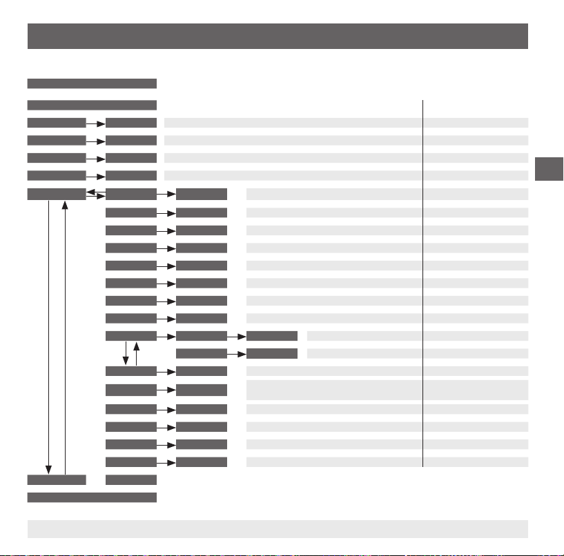
6. Mise en service, exploitation
Menu (programmation et réglage d'usine)
Mode d'achage
Pression longue sur la touche "MENU"
▲ ▼
Mode de programmation
▲ ▼
SP1 / FH1
▲ ▼
RP1 / FL1
▲ ▼
SP2 / FH2
▲ ▼
RP2 / FL2
▲ ▼
EF RES
END END
▼ ▼ ▼ ▼
Mode d'achage
11613025.02 12/2011 GB/D/F/E
Valeur
Valeur
Valeur
Valeur
▲ ▼
DS1
▲ ▼
DR1
▲ ▼
DS2
▲ ▼
DR2
▲ ▼
OU1
▲ ▼
OU2
▲ ▼
Unité
▲ ▼
SETR
OFS
▲ ▼
DISM
▲ ▼
DISR
▲ ▼
RHL
▲ ▼
PAS
▲ ▼
TAG
▲ ▼
Min: MBA + 0,5 %, Max: MBE MBE
Min: MBA, Max: SP1 - 0,5 % MBE -10 %
Min: MBA + 0,5 %, Max: MBE MBE
Min: MBA, Max: SP2 - 0,5 % MBE -10%
Oui / Non
Valeur
Valeur
Valeur
Valeur
PARA
PARA
Unité
4 mA / 0V Valeur
▲ ▼
20 mA / 10V Valeur
Oui / Non
PARA
Oui / Non
Oui / Non
Valeur
Valeur
Légende :
MBA = Démarrage de l'étendue de mesure
MBE = Fin de l'étendue de mesure
Réglage d'usine :
Retour au réglage d'usine
0 ... 50 s 0 s
0 ... 50 s 0 s
0 ... 50 s 0 s
0 ... 50 s 0 s
HNO, HNC, FNO, FNC HNO
HNO, HNC, FNO, FNC HNO
°C, °F Relatif à la commande
MBA - 25 %
MBE + 25 %
Réglage de l'oset 3 % de l'échelle 0 s
ACT, HIGH, LOW, OFF, SP1/FH1, RP1/FL1,
SP2/FH2, RP2/FL2
Rotation de l'aiguille d'achage de 180°
Retour HIGH, LOW
Mot de passe sans
Numéro de point de mesure sans
de l‘échelle MBA
de l‘échelle MBE
ACT
F
67WIKA Mode d‘emploi thermostat type TSD-30
Page 68

6. Mise en service, exploitation
6.4 Fonctions de commutation
Fonction d'hystérésis
Si la température uctue autour du point de réglage, l'hystérésis garde
stable le statut de commutation des sorties. Lorsque la température
augmente, la sortie commute lorsque le point de seuils est atteint (SP).
■
Contact normalement ouvert (HNO) : activé
F
■
Contact normalement fermé (HNC) : inactivé
Lorsque la température retombe, la sortie ne va pas commuter en
retour avant que le point de retour (RP) soit atteint.
■
Contact normalement ouvert (HNO) : inactivé
■
Contact normalement fermé (HNC) : activé
Fonction de fenêtre
La fonction de fenêtre permet le contrôle d'une étendue dénie.
Lorsque la température se trouve entre Fenêtre High (FH) et Fenêtre
Low (FL), la sortie s'allume.
■
Contact normalement ouvert (FNO) : activé
■
Contact normalement fermé (FNC) : inactivé
Lorsque la température se trouve en-dehors de Fenêtre High (FH) et
Fenêtre Low (FL), la sortie ne commute pas.
Fig. : fonction d'hystérésis
■
Contact normalement ouvert (FNO) : inactivé
■
Contact normalement fermé (FNC) : activé
Fig. : fonction de fenêtre
Fig. : Fonction de fenêtre
68 WIKA Mode d'emploi thermostat type TSD-30
11613025.02 12/2011 GB/D/F/E
Page 69
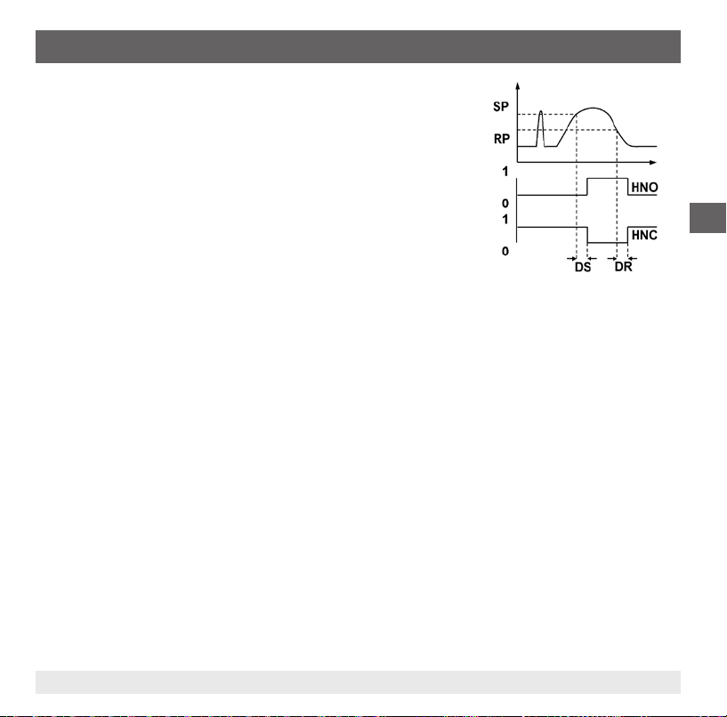
6. Mise en service, exploitation
Temps de temporisation (0 ... 50 s)
Ceci permet de se débarrasser de pics de température indésirables
d'une courte durée ou d'une haute fréquence (amortissement).
La température doit être présente pour au moins une certaine
durée préréglée pour que la sortie commute. La sortie ne change
pas immédiatement son statut lorsqu'elle atteint la situation de
commutation (SP), mais plutôt seulement après que la durée de
temporisation préréglée soit écoulée (DS).
Si la situation de commutation n'est plus présente après écoulement
de la durée de temporisation, la sortie de commutation ne change pas.
La sortie ne commute en retour que si la température est retombée au
point de retour (PR) et reste sur cette valeur ou tombe en-dessous de
ce point (RP) pour au moins la durée de temporisation préréglée (DR).
Si la situation de commutation n'est plus présente après écoulement
de la durée de temporisation, la sortie de commutation ne change pas.
F
Fig. : temps de temporisation
11613025.02 12/2011 GB/D/F/E
69WIKA Mode d‘emploi thermostat type TSD-30
Page 70
7. Entretien et nettoyage / 8. Dysfonctionnements
7. Entretien et nettoyage
7.1 Entretien
Le thermostat ne nécessite pas d'entretien.
Les réparations ne doivent être eectuées que par le fabricant.
7.2 Nettoyage
F
8. Dysfonctionnements
ATTENTION !
■
Nettoyer l'instrument avec un chion humide.
■
Eviter tout contact des raccordements électriques avec l'humidité.
■
Laver ou nettoyer l'instrument démonté avant de le renvoyer pour protéger le personnel et
l'environnement contre l'exposition à des restes de uides.
■
Les restes de uides se trouvant dans le thermostat démonté peuvent mettre en danger
les personnes, l'environnement ainsi que l'installation. Prendre des mesures de sécurité
susantes.
Indications concernant le retour de l'instrument, voir chapitre 9.2 "Retour".
Dans le cas de pannes, vérier d'abord si le thermostat est monté correctement, mécaniquement et électriquement.
Erreur d'achage
Par l'achage de l'instrument, les erreurs internes de l'instrument sont indiquées.
Le tableau suivant indique les codes d'erreur et leur signication.
70 WIKA Mode d'emploi thermostat type TSD-30
11613025.02 12/2011 GB/D/F/E
Page 71

8. Dysfonctionnements
Code d'erreur Description
ATT1 Lorsqu'on change le point de seuils, le système réduit automatiquement le point de retour.
ATT3 Le mot de passe entré pour l'accès au menu est incorrect
ERR Erreur interne
OL Étendue de mesure dépassée > environ 5 % (l'achage clignote)
UL En-dessous de l'étendue de mesure < environ 5 % (l'achage clignote)
On reconnaît un achage d'erreur en pressant la touche "Enter".
Problème Cause possible Mesure
Pas de signal de sortie Câble sectionné Vérier le perçage
Aucun signal de sortie/coupure
de l
Pas de signal de sortie Pas de/mauvaise alimentation Corriger l'alimentation
Pas de/mauvais signal de sortie Erreur de raccordement électrique Observer la conguration du
Mauvais signal de sortie Température du process en dehors de
Mauvais signal de sortie Dérive du capteur causée par une
Signal de sortie incorrect et temps
de réponse trop long
Plage de signaux trop petite Alimentation trop élevée/basse Corriger l'alimentation
Plage de signaux tombe L'humidité a pénétrée Monter le câble correctement
Si la réclamation n'est pas justiée, nous vous facturerons les frais de traitement de la réclamation
11613025.02 12/2011 GB/D/F/E
Charge mécanique trop élevée Remplacer le capteur avec une
l'étendue de mesure;
Dérive du capteur causée par une
température excessive
Rupture de capteur/court-circuit du
capteur
attaque chimique
Géométrie de montage incorrecte, par
exemple profondeur de montage trop
profonde ou dissipation thermique trop
élevée
Dépôt sur le capteur
conception adaptée
raccordement
Vérier la plage de température
Envoyer l'instrument au fabricant
Vérier la compatibilité avec des
produits
Déplacer la zone thermosensible
du capteur vers l'intérieur du uide
Enlever le dépôt
F
71WIKA Mode d‘emploi thermostat type TSD-30
Page 72
8. Dysfonctionnements / 9. Démontage, retour et mise au rebut
ATTENTION !
Si des dysfonctionnements ne peuvent pas être éliminés à l'aide des mesures indiquées
ci-dessus, lethermostat doit être immédiatement mis hors service, il faut s'assurer qu'aucun
signal n'est plus disponible et le protéger contre toute remise en service involontaire.
Contacter dans ce cas le fabricant. S'il est nécessaire de retourner l'instrument au fabricant,
respecter les indications mentionnées au chapitre 9.2 "Retour".
F
9. Démontage, retour et mise au rebut
AVERTISSEMENT !
Les restes de uides se trouvant dans le thermostat démonté peuvent mettre en danger les
personnes, l’environnement ainsi que l’installation.
Prendre des mesures de sécurité susantes.
9.1 Démontage
AVERTISSEMENT !
Danger de brûlure !
Avant le démontage du thermomètre, laisser refroidir susamment l’instrument !
Danger de brûlure lié à la sortie de uides dangereux chauds.
9.2 Retour
AVERTISSEMENT !
En cas d’envoi de l’instrument, il faut respecter impérativement ceci :
Tous les instruments envoyés à WIKA doivent être exempts de toute substance dangereuse
(acides, lixiviats, solutions, etc.).
Pour retourner l’instrument, utiliser l’emballage original ou un emballage adapté pour le transport.
72 WIKA Mode d'emploi thermostat type TSD-30
11613025.02 12/2011 GB/D/F/E
Page 73

9. Démontage, retour et mise au rebut
Joindre le formulaire de retour rempli à l'instrument.
Le formulaire de retour est disponible sous le titre 'Service' à www.wika.com.
9.3 Mise au rebut
Une mise au rebut inadéquate peut entraîner des dangers pour l'environnement.
Eliminer les composants des instruments et les matériaux d'emballage conformément aux prescriptions
nationales pour le traitement et l'élimination des déchets et aux lois de protection de l'environnement en
vigueur.
11613025.02 12/2011 GB/D/F/E
F
73WIKA Mode d‘emploi thermostat type TSD-30
Page 74

Annexe 1: Déclaration de conformité CE type TSD-30
F
74 WIKA Mode d'emploi thermostat type TSD-30
11613025.02 12/2011 GB/D/F/E
Page 75

Contenido
Contenido
1. Información general 76
2. Seguridad 78
3. Datos técnicos 81
4. Diseño y función 85
5. Transporte, embalaje y almacenamiento 86
6. Puesta en servicio, funcionamiento 86
7. Mantenimiento y limpieza 94
8. Fallos 94
9. Desmontaje, devolución y eliminación 96
10. Anexo 1: Declaración CE de conformidad Modelo TSD-30 98
Declaraciones de conformidad puede encontrar en www.wika.es.
11613025.02 12/2011 GB/D/F/E
E
75WIKA manual de instrucciones termóstato modelo TSD-30
Page 76

1. Información general
1. Información general
■
El termostato descrito en el manual de instrucciones está construido y fabricado según los conocimientos actuales. Todos los componentes están sujetos a rigurosos criterios de calidad y medio
ambiente durante la producción. Nuestros sistemas de gestión están certicados según ISO 9001 e
ISO 14001.
■
Este manual de instrucciones proporciona indicaciones importantes acerca del manejo del instrumento. Para que el trabajo con este instrumento sea seguro es imprescindible cumplir con todas las
instrucciones de seguridad y manejo indicadas.
E
■
Cumplir siempre las normativas sobre la prevención de accidentes y las normas de seguridad en
vigor en el lugar de utilización del instrumento.
■
El manual de instrucciones es una parte integrante del instrumento y debe guardarse en la proximidad del mismo para que el personal especializado pueda consultarlo en cualquier momento.
■
El personal especializado debe haber leído y entendido el manual de instrucciones antes de comenzar cualquier trabajo.
■
El fabricante queda exento de cualquier responsabilidad en caso de daños causados por un uso no
conforme a la nalidad prevista, la inobservancia del presente manual de instrucciones, un manejo
por personal insucientemente cualicado así como una modicación no autorizada del instrumento.
■
Se aplican las condiciones generales de venta incluidas en la documentación de venta.
■
Modicaciones técnicas reservadas.
■
Para obtener más informaciones consultar:
- Página web: www.wika.es
- Hoja técnica correspondiente: TE 67.03
- Servicio técnico:
Tel.: (+34) 933 938-630
Fax: (+34) 933 938-666
E-Mail: info@wika.es
76 WIKA manual de instrucciones termóstato modelo TSD-30
11613025.02 12/2011 GB/D/F/E
Page 77

1. Información general
Explicación de símbolos
¡ADVERTENCIA!
… indica una situación probablemente peligrosa que pueda causar la muerte o lesiones
graves si no se evita.
¡CUIDADO!
... indica una situación probablemente peligrosa que pueda causar lesiones leves o
medianas o daños materiales y medioambientales si no se evita.
Información
... destaca consejos y recomendaciones útiles así como informaciones para una utilización
ecaz y libre de fallos.
¡CUIDADO!
... indica una situación probablemente peligrosa que pueda causar quemaduras debido a
supercies o líquidos calientes si no se evita.
Abreviaturas
U
+
U
-
S
+
SP1 1 punto de interrupción
SP2 2 punto de interrupción
MBA Valor inicial del rango de medida
MBE Final del rango de medida
Acometida positiva
Potencial de referencia
Salida analógica
E
11613025.02 12/2011 GB/D/F/E
77WIKA manual de instrucciones termóstato modelo TSD-30
Page 78

2. Seguridad
2. Seguridad
¡ADVERTENCIA!
Antes del montaje, la puesta servicio y el funcionamiento asegurarse de que se haya seleccionado el termostato adecuado con respecto a rango de medida, versión y condiciones de
medición especícas.
La inobservancia puede causar lesiones graves y/o daños materiales.
¡ADVERTENCIA!
E
2.1 Uso conforme a lo previsto
El termostato sirve para convertir la temperatura en una señal eléctrica en interiores y exteriores.
El instrumento ha sido diseñado y construido únicamente para la nalidad aquí descrita y debe
utilizarse en conformidad a la misma.
Hay que observar las especicaciones técnicas indicadas en este manual de instrucciones. Un manejo
no apropiado o una utilización del termostato no conforme a las especicaciones técnicas requiere la
inmediata puesta fuera de servicio y la comprobación por parte de un técnico autorizado por WIKA.
No se admite ninguna reclamación debido a un manejo no adecuado.
Tener en cuenta los parámetros de servicio según el capítulo 3 "Datos técnicos".
Los distintos capítulos de este manual de instrucciones contienen otras importantes
indicaciones de seguridad.
78 WIKA manual de instrucciones termóstato modelo TSD-30
11613025.02 12/2011 GB/D/F/E
Page 79

2. Seguridad
2.2 Cualicación del personal
¡ADVERTENCIA!
¡Riesgo de lesiones debido a una insuciente cualicación!
Un manejo no adecuado puede causar considerables daños personales y materiales.
Las actividades descritas en este manual de instrucciones deben realizarse únicamente
por personal especializado con la consiguiente cualicación.
Personal especializado
Debido a su formación profesional, a sus conocimientos de la técnica de regulación y medición así
como a su experiencia y su conocimiento de las normativas, normas y directivas vigentes en el país de
utilización el personal especializado es capaz de ejecutar los trabajos descritos y reconocer posibles
peligros por sí solo.
Algunas condiciones de uso especícas requieren conocimientos adicionales, p. ej. acerca de medios
agresivos.
2.3 Riesgos especícos
¡ADVERTENCIA!
En el caso de sustancias peligrosas a medir, como p. ej. oxígeno, acetileno, sustancias
inamables o tóxicas, así como en instalaciones de refrigeración, compresores, etc.,
deben observarse en cada caso, además de todas las reglas generales, las disposiciones
pertinentes.
¡ADVERTENCIA!
Restos de medios en termostatos desmontados pueden crear riesgos para personas,
medio ambiente e instalación.
Tomar adecuadas medidas de precaución.
E
11613025.02 12/2011 GB/D/F/E
79WIKA manual de instrucciones termóstato modelo TSD-30
Page 80
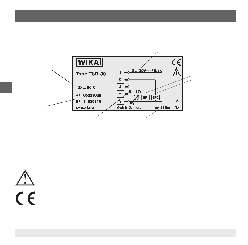
2. Seguridad
2.4 Rótulos / Marcados de seguridad
Placa indicadora de modelo
Rango de medida
E
P# nº de artículo
S# nº de serie
Corriente auxiliar
Salida de conexión 1
Salida de conexión 2
Señal analógica
Presión de trabajo máxima
Si el número de serie queda ilegible (por ejemplo por daños mecánicos o tras pintar por encima), ya no
se puede mantener la trazabilidad.
Explicación de símbolos
Símbolo general de riesgos
CE, Communauté Européenne
Los instrumentos con este marcaje cumplen las directivas europeas aplicables.
80 WIKA manual de instrucciones termóstato modelo TSD-30
11613025.02 12/2011 GB/D/F/E
Page 81

3. Datos técnicos
3. Datos técnicos
3.1 Rangos de medida
Temperatura Estándar Opción
°C -20 ... +80 -20 ... +120
°F -4 ... +176 -4 ... +248
1) véase “Condiciones de utilización”
1)
3.2 Pantalla
LCD de 14 segmentos, rojo, de 4 dígitos, altura de las cifras: 9 mm
La visualización puede girarse electrónicamente a 180°
Actualización
200 ms
3.3 Señal de salida
Salida de conexión 1 Salida de conexión 2 Señal analógica
PNP - 4 ... 20 mA
PNP - DC 0 ... 10 V
PNP PNP PNP PNP 4 ... 20 mA
PNP PNP DC 0 ... 10 V
También disponible con salida de conexión NPN en lugar de PNP
Ajuste de temperatura (oset)
± 3 % del alcance
Subdivisión
Punto cero: máx. +25 % del alcance
Valor nal: máx. -25 % del alcance
11613025.02 12/2011 GB/D/F/E
E
81WIKA manual de instrucciones termóstato modelo TSD-30
Page 82
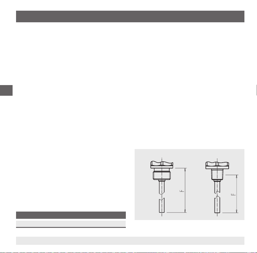
3. Datos técnicos
Señal analógica
Carga
■
Corriente: ≤ 500 Ω
■
Tensión: > 10 kΩ
Salida de conexión
Los puntos de conmutación 1 y 2 pueden ajustarse individualmente
Funcionamiento
■
Contacto normalmente abierto / cerrado: ajustable libremente
■
Ventana e histéresis: ajustable libremente
E
Tensión de conmutación: Corriente auxiliar – 1 V
Corriente de conmutación: máx. 250 mA por salida de conexión
Tiempo de respuesta: ≤ 200 ms
precisión de ajuste:
3.4 Alimentación de corriente
Corriente auxiliar
DC 15 ... 35 V
Consumo de electricidad
máx. 100 mA
Alimentación de corriente eléctrica total
máx. 600 mA (incl. corriente de conmutación)
3.5 Elemento de medición
Pt1000, 2 hilos, DIN EN 60751 / clase A
Longitud de montaje (F)
F en mm
25 50 100 150 250 350
≤ 0,5 % del alcance
Fig. Longitud de montaje (F)
Rosca cilíndrica Rosca cónica
82 WIKA manual de instrucciones termóstato modelo TSD-30
11613025.02 12/2011 GB/D/F/E
Page 83

3. Datos técnicos
Tiempo de reacción
T05 < 5 s (según DIN EN 60751)
T09 < 10 s (según DIN EN 60751)
Presión de trabajo máxima
150 bar
3.5 Precisión
Señal analógica
≤. ± 0,5 % del alcance
Salida de conexión
≤ ± 0,8 % del alcance
Indicador
≤ ± 0,8 % del alcance ± 1 dígito
Sensor de temperatura
± (0,15 K + 0,002 |t|)
| t | es el valor numérico de la temperatura en ºC sin considerar el signo.
La precisión efectiva es determinada en gran medida por las condiciones de montaje (profundidad
de inmersión, longitud del sensor, condiciones de uso). Ello vale especialmente en caso de grandes
gradientes térmicos entre ambiente y medio.
3.6 Condiciones de referencia
Temperatura: 15 ... 25 °C
Presión atmosférica: 950 ... 1.050 mbar
Humedad atmosférica: 45 ... 75 % relativa
Posición nominal: Conexión a proceso inferior
Alimentación auxiliar: DC 24 V
Carga: véase "señal de salida"
11613025.02 12/2011 GB/D/F/E
E
83WIKA manual de instrucciones termóstato modelo TSD-30
Page 84

3. Datos técnicos
3.7 Condiciones de utilización
Temperaturas y humedad atmosférica
Temperatura del medio: -20 ... +80 °C
Temperatura ambiente: -20 ... +80 °C
Temperatura de almacenamiento: -20 ... +80 °C
Humedad del aire permitida: 45 ... 75 % relativa
Instrucciones de montaje
Posición de montaje: cualquiera
Con temperaturas del medio o ambiente elevadas se debe asegurar que la temperatura de la caja del
E
instrumento no supera los 80 °C en servicio continuo (la temperatura se mide en el hexágono de la
conexión al proceso).
A temperaturas superiores a 80 °C la rosca no debe estar sumergida en el medio.
3.8 Materiales
Piezas en contacto con el medio
Sensor de temperatura: Acero inoxidable 316Ti
Piezas sin contacto con el medio
Caja: Acero inoxidable 304
Teclado: TPE-E
Cristal de la pantalla: PC
Cabezal indicador: Combinación de PC + ABS
3.9 Homologaciones, directivas y certicados
Conformidad CE
Directiva de EMC: 2004/108/CE, EN 61326 Emisión (grupo 1, clase B) y resistencia a interferencias
Conformidad RoHS: Sí
(ámbito industrial)
84 WIKA manual de instrucciones termóstato modelo TSD-30
11613025.02 12/2011 GB/D/F/E
Page 85

3. Datos técnicos / 4. Diseño y función
3.10 Conexiones eléctricas
Conexiones
Clavija de enchufe, M12 x 1, de 4 polos
Clavija de enchufe, M12 x 1, de 5 polos
1) Solamente en versión con dos salidas de señal y señal analógica
Tipo de protección
IP 65 y IP 67
Los tipos de protección indicados (según IEC 60529) sólo son válidos en estado conectado con conectores según el modo de protección
correspondiente.
Protección eléctrica
Resistencia contra cortocircuitos: S+ / SP1 / SP2 contra U
Protección contra polaridad inversa: U+ contra U
Tensión de aislamiento: DC 500 V
Protección contra sobretensiones: DC 40 V
Para más datos técnicos véase la hoja técnica de WIKA TE 67.03 y la documentación de pedido.
4. Diseño y función
4.1 Descripción
Con la ayuda de un elemento de medición (Pt1000) y la alimentación de energía auxiliar, la temperatura
existente es convertida, mediante la modicación de la resistencia de dicho elemento de medición, en
una señal de conmutación o en una señal eléctrica estandarizada y amplicada. Esta señal eléctrica se
modica proporcionalmente en función de la temperatura, permitiendo así su análisis.
1)
-
-
E
4.2 Volumen de suministro
Comparar mediante el albarán si se han entregado todas las piezas.
11613025.02 12/2011 GB/D/F/E
85WIKA manual de instrucciones termóstato modelo TSD-30
Page 86
5. Transporte, embalaje y almacenamiento / 6. Puesta en servicio, ...
5. Transporte, embalaje y almacenamiento
5.1 Transporte
Comprobar si el termostato presenta eventuales daños causados en el transporte.
Noticar de inmediato cualquier daño evidente.
5.2 Embalaje
No quitar el embalaje hasta justo antes del montaje.
Guardar el embalaje ya que es la protección ideal durante el transporte (por ejemplo si el lugar de instalación cambia o si se envía el instrumento para posibles reparaciones).
E
5.3 Almacenamiento
Condiciones admisibles en el lugar de almacenamiento:
■
Temperatura de almacenamiento: -20 ... +80 °C
■
Humedad: 45 ... 75 % de humedad relativa
¡ADVERTENCIA!
Antes de almacenar el instrumento (después del funcionamiento), eliminar todos los restos
de medios adherentes. Esto es especialmente importante cuando el medio es nocivo para la
salud, como p. ej. cáustico, tóxico, cancerígeno, radioactivo, etc.
6. Puesta en servicio, funcionamiento
6.1 Montaje
Herramienta necesaria: Llave de boca (ancho 27)
■
Las supercies de obturación en el termostato y en el punto de medición deben estar siempre libres
de suciedad.
■
Atornillar y desatornillar el instrumento únicamente aplicando la llave en las supercies previstas
para ello. Nunca utilizar la caja como supercie de ataque.
86 WIKA manual de instrucciones termóstato modelo TSD-30
11613025.02 12/2011 GB/D/F/E
Page 87
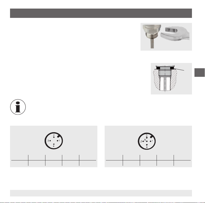
6. Puesta en servicio, funcionamiento
■
El par de giro correcto depende de la dimensión de la conexión así
como de la junta utilizada (forma/material).
■
No bloquear las vueltas de la rosca al enroscar.
■
Las indicaciones sobre taladros para roscar y para soldar están en
nuestra información técnica IN 00.14 en www.wika.es.
■
¡Poner a tierra el instrumento través de la conexión.
■
Enchufar el conector y atornillarlo a mano.
Sellado
Para el sellado de las conexiones al proceso con roscas rectas en la supercie
de obturación se deben instalar juntas planas, arandelas o juntas perladas
WIKA.
Para roscas cónicas (por ejemplo, roscas NPT) se realiza el sellado en
la rosca
con materiales de sellado complementarios, como por ejemplo, cinta
PTFE (EN 837-2).
Para notas acerca de las juntas, véase la hoja técnica WIKA AC 09.08 o www.wika.es.
Esquemas de conexiones
Clavija de enchufe, M12 x 1, de 4 polos
Clavija de enchufe, M12 x 1, de 5 polos
E
Asignación
+
U- S
+
U
1 3 2 4 2
11613025.02 12/2011 GB/D/F/E
SP1 SP2
Asignación
+
U- S
U
1 3 5 4 2
+
SP1 SP2
87WIKA manual de instrucciones termóstato modelo TSD-30
Page 88
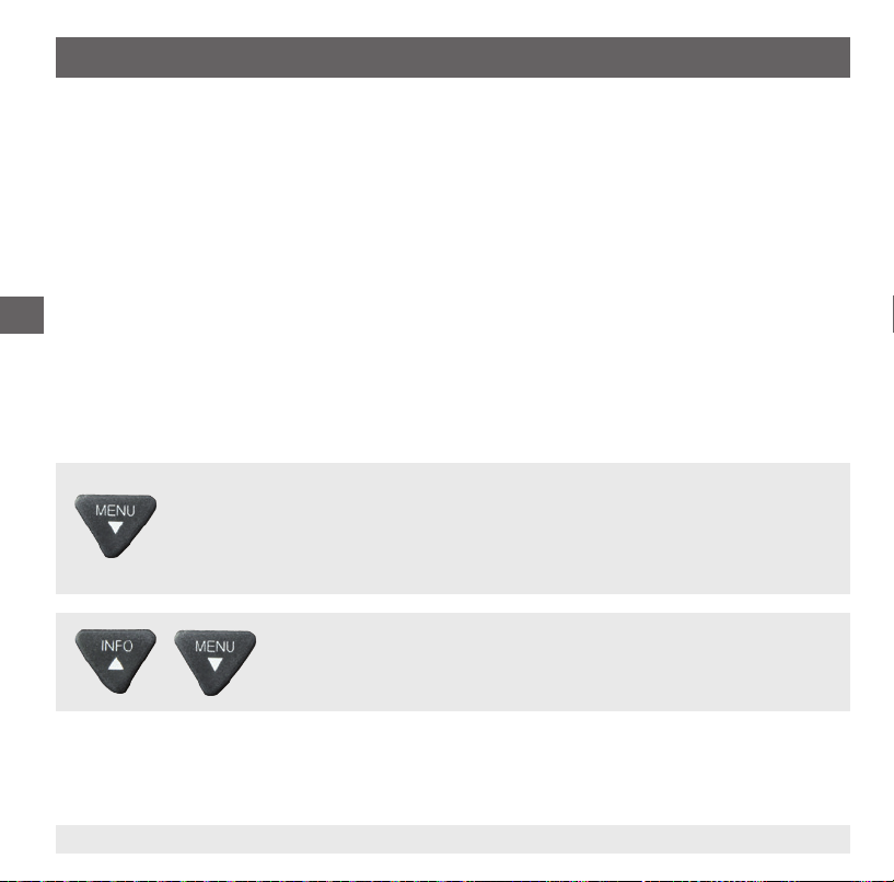
6. Puesta en servicio, funcionamiento
6.2 Modos de servicio
Arranque del sistema
■
La pantalla se activa sin interrupción durante 2 segundo.
■
Al arrancar el termostato en el rango de la histéresis, el interruptor de salida se coloca de manera
estándar en "no activo"
Modo de visualización
Actividad normal de trabajo, visualización de la temperatura
E
Modo de programación
Ajustar los parámetros
6.3 Teclas y funciones
El termostato cuenta con dos modos de servicio, el modo de visualización y el modo de programación.
El modo de servicio seleccionado determina la correspondiente función de la tecla.
Salto al modo de programación
Pulsar la tecla "MENÚ" durante aprox. 5 segundo. Si está ajustada una contraseña
≠ 0000, se requerirá introducir una contraseña. Si ello se efectúa satisfactoriamente, se
accede al modo de programación; de otro modo se regresa al modo de visualización.
Regreso al modo de visualización
Accionamiento simultáneo de ambas teclas.
88 WIKA manual de instrucciones termóstato modelo TSD-30
11613025.02 12/2011 GB/D/F/E
Page 89
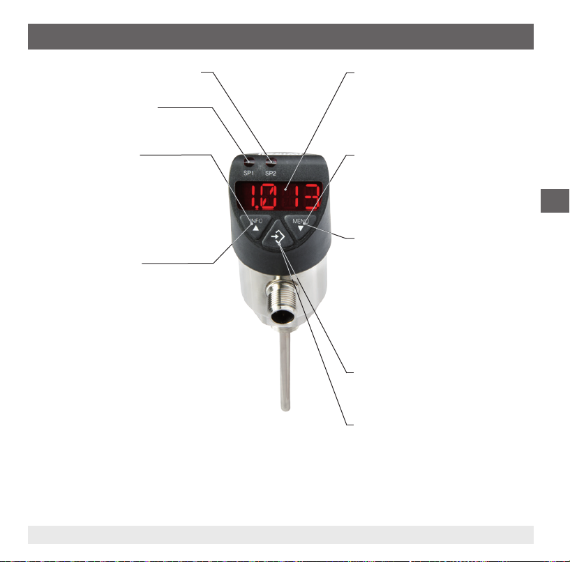
6. Puesta en servicio, funcionamiento
Estado salida de conexión 2 (opcional)
Estado salida de conexión 1
Modo de visualización
▶ Accionamiento breve:
Visualización de la unidad
▶ Accionamiento largo:
Para visualización de los parámetros ajustados, véase el capítulo 6.4
"Parámetros"
Modo de programación
▶ Accionamiento breve:
Menú hacia arriba
Parámetro hacia arriba (gradualmente)
▶ Accionamiento largo:
Menú hacia arriba
Parámetro hacia arriba (rápido)
Indicador LED de 4 dígitos
■
Visualización de la temperatura
■
Visualización de la opción del menú
■
Visualización de los parámetros
Modo de visualización
▶ Accionamiento breve:
Visualización de la unidad
▶ Accionamiento largo:
Salto al modo de programación
Modo de programación
▶ Accionamiento breve:
Menú hacia arriba
Parámetro hacia arriba (gradualmente)
▶ Accionamiento largo:
Menú hacia arriba
Parámetro hacia arriba (rápido)
Modo de visualización
▶ Accionamiento breve:
Visualización de la unidad
Modo de programación
▶ Accionamiento breve:
Selección de la opción del menú
Conrmación de la introducción
E
11613025.02 12/2011 GB/D/F/E
89WIKA manual de instrucciones termóstato modelo TSD-30
Page 90

6. Puesta en servicio, funcionamiento
6.4 Parámetro
Parámetro Descripción
SP1/SP2 Función de histéresis: punto de conmutación de la salida de conexión (1 ó 2)
FH1/FH2 Función de ventana: ventana High de la salida de conexión (1 ó 2)
RP1/RP2 Función de histéresis: punto de retroceso de la salida de conexión (1 ó 2)
FL1/FL2 Función de ventana: ventana Low de la salida de conexión (1 ó 2)
EF Funciones de programación ampliadas
RES Reponer los parámetros ajustados a los ajustes de fábrica
E
DS1/DS2 Tiempo de recuperación de la conexión que debe estar presente sin interrupción hasta que se realice
DR1/DR2 Tiempo de recuperación de la conexión que debe estar presente sin interrupción hasta que se realice
OU1 Función de conmutación de la salida de conexión (1 ó 2)
OU2 HNO = función de histéresis, contacto normalmente abierto
UNIT Conmutación de la unidad
SETR
OFS Ajuste del oset (3 % del alcance)
DISM Valor visualizado en el modo de pantalla
DISR Girar la pantalla por 180°
RHL Borrar la memoria de los valores mín./máx.
PAS Introducción de la contraseña, 0000 = sin contraseña, Introducción de la contraseña dígito por dígito
TAG Introducción del número alfanumérico de 16 dígitos del punto de medición
90 WIKA manual de instrucciones termóstato modelo TSD-30
un cambio eléctrico de señal (SP1 o SP2)
un cambio eléctrico de señal (RP1 o RP2)
HNC = histéresis, contacto normalmente cerrado
FNO = función de ventana, contacto normalmente abierto
FNC = función de ventana, contacto normalmente cerrado
(Si el rango de medida se encuentra fuera del rango de visualización, no es posible una conmutación
de unidades y no se visualiza el parámetro UNIT)
Subdivisión del rango de medida (salida analógica)
“4 mA” ó “0 V” dene la temperatura con que la señal de salida debe ser 4 mA ó 0 V.
“20 mA” ó “10 V” dene la temperatura con que la señal de salida debe ser 20 mA ó 10 V.
ACT = Temperatura actual; LOW, HIGH = Temperatura mínima, máxima OFF = visualización apagada;
SP1/FH1 = Función punto de conmutación 1, RP1/FL1 = Función punto de retroceso 1,
SP2/FH2 = Función punto de conmutación 2, RP2/FL2 = Función punto de retroceso 2,
11613025.02 12/2011 GB/D/F/E
Page 91

6. Puesta en servicio, funcionamiento
Menú (programación y ajuste de fábrica)
Modo de pantalla
Accionamiento prolongado de la tecla "MENÚ"
▲ ▼
Modo de programación
▲ ▼
SP1 / FH1
▲ ▼
RP1 / FL1
▲ ▼
SP2 / FH2
▲ ▼
RP2 / FL2
▲ ▼
EF RES
END END
▼ ▼ ▼ ▼
Modo de pantalla
11613025.02 12/2011 GB/D/F/E
Valor
Valor
Valor
Valor
▲ ▼
DS1
▲ ▼
DR1
▲ ▼
DS2
▲ ▼
DR2
▲ ▼
OU1
▲ ▼
OU2
▲ ▼
UNIT
▲ ▼
SETR
OFS
▲ ▼
▲ ▼
DISR
▲ ▼
RHL
▲ ▼
PAS
▲ ▼
TAG
▲ ▼
Mín: MBA +0,5 %, Máx: MBE MBE
Mín: MBA, Máx: SP1 -0,5 % MBE -10 %
Mín: MBA +0,5 %, Máx: MBE MBE
Mín: MBA, Máx: SP2 -0,5 % MBE -10 %
Yes / No
Valor
Valor
Valor
Valor
PARA
PARA
Unidad
4 mA / 0V Valor
▲ ▼
20 mA / 10V Valor
Yes / No
PARA
Sí / no
Yes / No
Valor
Valor
Leyenda:
MBA = Valor inicial del rango de medida
MBE = Final del rango de medida
Restablecer el ajuste de fábrica
0 ... 50 s 0 s
0 ... 50 s 0 s
0 ... 50 s 0 s
0 ... 50 s 0 s
HNO, HNC, FNO, FNC HNO
HNO, HNC, FNO, FNC HNO
°C, °F Según pedido
6.2 Ajuste del oset 3 % del alcance 0 s
ACT, HIGH, LOW, OFF, SP1/FH1, RP1/FL1,
SP2/FH2, RP2/FL2
Girar 180° la pantalla
Reponer HIGH, LOW
Contraseña sin
Número del punto de medición sin
MBA - 25 %
MBE + 25 %
Ajuste de fábrica:
E
del alcance MBA
del alcance MBE
ACTDISM
91WIKA manual de instrucciones termóstato modelo TSD-30
Page 92

6. Puesta en servicio, funcionamiento
6.4 Función de conmutación
Función de histéresis
Si la temperatura se acerca pero no alcanza el valor nominal, la
histéresis mantiene estable el estado de conmutación de las salidas.
Al aumentar la temperatura, la salida conmuta al alcanzarse el punto
de conmutación (SP).
■
Contacto de trabajo (HNO): activo
■
Contacto de ruptura (HNC): inactivo
E
Si la temperatura de trabajo vuelve a caer, la salida conmuta a la
posición anterior tan solo una vez alcanzado el punto de retroceso
(RP).
■
Contacto de trabajo (HNO): inactivo
■
Contacto de ruptura (HNC): activo
Función de ventana
La función de ventana permite de controlar una zona determinada.
Si la temperatura se encuentra entre la ventana High (FH) y la ventana
Low (FL), la salida conmuta.
■
Contacto de trabajo (FNO): activo
■
Contacto de ruptura (FNC): inactivo
Fig.: Función de histéresis
Si la temperatura se encuentra fuera de la ventana High (FH) y la
ventana Low (FL), la salida no conmuta.
■
Contacto de trabajo (FNO): inactivo
■
Contacto de ruptura (FNC): activo
Fig.: Función de ventana
92 WIKA manual de instrucciones termóstato modelo TSD-30
11613025.02 12/2011 GB/D/F/E
Page 93

6. Puesta en servicio, funcionamiento
Tiempo de recuperación (de 0 a 50 s)
Así pueden ltrarse los picos de temperatura breves o de alta
frecuencia no deseados (amortiguación).
Para que la salida conmute, la temperatura debe aplicarse por
lo menos el tiempo preajustado. La salida no cambia su estado
inmediatamente después de alcanzar el evento de conmutación (SP),
sino una vez expirado el tiempo de retardo ajustado (DS).
Si el evento de conmutación ya no está presente después de la
terminación del tiempo de recuperación, la salida de conexión no se
modica.
La salida conmuta a la posición anterior tan solo cuando la
temperatura ha caído al punto de retroceso (RP) y permanece en
dicho punto o por debajo de él por lo menos el tiempo de retardo (DR)
ajustado.
Si el evento de conmutación ya no está presente después de la
terminación del tiempo de recuperación, la salida de conexión no se
modica.
E
Fig.: Tiempos de retardo
11613025.02 12/2011 GB/D/F/E
93WIKA manual de instrucciones termóstato modelo TSD-30
Page 94

7. Mantenimiento y limpieza / 8. Fallos
7. Mantenimiento y limpieza
7.1 Mantenimiento
El termostato no requiere mantenimiento.
Todas las reparaciones las debe efectuar únicamente el fabricante.
7.2 Limpieza
¡CUIDADO!
■
E
8. Fallos
Limpiar el instrumento con un trapo húmedo.
■
Asegurarse de que las conexiones eléctricas no se humedecen.
■
Una vez desmontado el instrumento se debe enjuagar y limpiar antes de devolverlo para
proteger a las personas y el medio ambiente contra residuos del medio de medición.
■
Restos de medios en termostatos desmontados pueden crear riesgos para personas,
medio ambiente e instalación. Tomar adecuadas medidas de precaución.
Véase el capítulo 9.2 "Devolución" para obtener más información acerca de la devolución
del instrumento.
En caso de averías, comprobar en primer lugar la correcta conexión mecánica y eléctrica
del termostato.
Indicación de errores
En la pantalla del instrumento se visualizan los fallos internos.
La siguiente tabla muestra los códigos de fallo y su signicado.
94 WIKA manual de instrucciones termóstato modelo TSD-30
11613025.02 12/2011 GB/D/F/E
Page 95

8. Fallos
Código de error Descripción
ATT1 Modicando el punto de conmutación se ha rebajado automáticamente el punto de retro-
ATT3 Introducción de la contraseña para el acceso al menú non correcta
ERR Error interno
OL Rango de medida sobrepasado > aprox. 5 % (indicador parpadea)
UL Se ha quedado debajo del rango de medida de aprox. un 5 % (pantalla parpadea)
ceso del sistema
Conrmar la indicación de fallos pulsando la tecla "Enter".
Fallo Posible causa Medida
Ninguna señal de salida Cable roto Comprobar el paso
Ninguna señal de salida / rotura
de cable
Ninguna señal de salida Energía auxiliar errónea/ausente Corregir la corriente auxiliar
Señal de salida ausente/errónea Fallo de cableado
Señal de salida errónea Temperatura del proceso fuera del
Señal de salida errónea Desviación por ataque químico Comprobar la compatibilidad con el
Señal de salida errónea y tiempo de
reacción demasiado prolongado
Insuciente alcance de señal Corriente auxiliar demasiado alta/
Alcance de señal se cae Penetró humedad Montar correctamente el cable
En caso de reclamar una garantía sin que ésta esté justicada, facturaremos los gastos de tramitación de la reclamación.
11613025.02 12/2011 GB/D/F/E
Carga mecánica excesiva Sustituir el sensor por una versión
rango de medición;
Desviación por sobretemperatura
Rotura/cortocircuito del sensor
Geometría de montaje errónea,
p Ej. profundidad de montaje
demasiado reducida y disipación
de calor muy elevada
Sedimentos en el sensor
baja
adecuada
Tener en cuenta detalles del conexionado
Conprobar el rango de temperatura
Enviar el instrumento al fabricante
medio
Colocar en el medio la zona del sensor
sensible a la temperatura
Remover los sedimentos
Corregir la corriente auxiliar
E
95WIKA manual de instrucciones termóstato modelo TSD-30
Page 96
8. Fallos 9. Desmontaje, devolución y eliminación
¡CUIDADO!
Si no es posible corregir los defectos mediante las medidas detalladas arriba, se debe
poner el termostato inmediatamente fuera de servicio y prevenir una puesta en servicio
errónea. En tal caso se debe consultar el fabricante. En caso de devolución respetar los
comentarios en capítulo 9.2. "Devoluciones".
9. Desmontaje, devolución y eliminación
E
9.1 Desmontaje
9.2 Devolución
Utilizar el embalaje original o un embalaje adecuado para la devolución del instrumento.
96 WIKA manual de instrucciones termóstato modelo TSD-30
¡ADVERTENCIA!
Restos de medios en termostatos desmontados pueden crear riesgos para personas,
medio ambiente e instalación.
Tomar adecuadas medidas de precaución.
¡ADVERTENCIA!
¡Riesgo de quemaduras!
¡Dejar enfriar el instrumento lo suciente antes de desmontarlo!
Peligro debido a medios muy calientes que se escapan durante el desmontaje.
¡ADVERTENCIA!
Es imprescindible observar lo siguiente para el envío del instrumento:
Todos los instrumentos enviados a WIKA deben estar libres de sustancias peligrosas
(ácidos, lejías, soluciones, etc.).
11613025.02 12/2011 GB/D/F/E
Page 97

9. Desmontaje, devolución y eliminación
Rellenar el formulario de devolución y adjuntarlo al instrumento.
El formulario de devolución está disponible en internet: www.wika.es / Servicio / Devoluciones
9.3 Eliminación de residuos
Una eliminación incorrecta puede provocar peligros para el medio ambiente.
Eliminar los componentes de los instrumentos y los materiales de embalaje conforme a los reglamentos
relativos al tratamiento de residuos y eliminación vigentes en el país de utilización.
E
11613025.02 12/2011 GB/D/F/E
97WIKA manual de instrucciones termóstato modelo TSD-30
Page 98
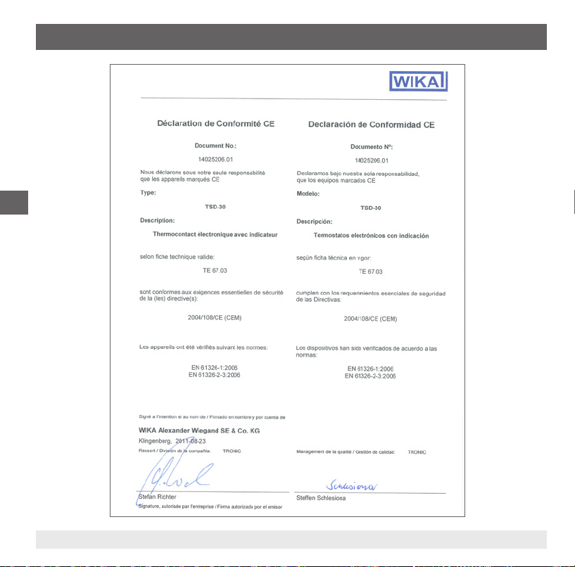
Anexo 1: Declaración CE de conformidad Modelo TSD-30
E
98 WIKA manual de instrucciones termóstato modelo TSD-30
11613025.02 12/2011 GB/D/F/E
Page 99

WIKA global
Europe
Austria
WIKA Messgerätevertrieb
Ursula Wiegand
GmbH & Co. KG
1230 Vienna
Tel. (+43) 1 86916-31
Fax: (+43) 1 86916-34
E-Mail: info@wika.at
www.wika.at
Benelux
WIKA Benelux
6101 WX Echt
Tel. (+31) 475 535-500
Fax: (+31) 475 535-446
E-Mail: info@wika.nl
www.wika.nl
Bulgaria
WIKA Bulgaria EOOD
Bul. „Al. Stamboliiski“ 205
1309 Soa
Tel. (+359) 2 82138-10
Fax: (+359) 2 82138-13
E-Mail: t.antonov@wika.bg
Croatia
WIKA Croatia d.o.o.
Hrastovicka 19
10250 Zagreb-Lucko
Tel. (+385) 1 6531034
Fax: (+385) 1 6531357
E-Mail: info@wika.hr
www.wika.hr
11613025.01 10/2011 GB/D/F/E
Finland
WIKA Finland Oy
00210 Helsinki
Tel. (+358) 9-682 49 20
Fax: (+358) 9-682 49 270
E-Mail: info@wika.
www.wika.
France
WIKA Instruments s.a.r.l.
95610 Eragny-sur-Oise
Tel. (+33) 1 343084-84
Fax: (+33) 1 343084-94
E-Mail: info@wika.fr
www.wika.fr
Germany
WIKA Alexander Wiegand
SE & Co. KG
63911 Klingenberg
Tel. (+49) 9372 132-0
Fax: (+49) 9372 132-406
E-Mail: info@wika.de
www.wika.de
Italy
WIKA Italia Srl & C. Sas
20020 Arese (Milano)
Tel. (+39) 02 9386-11
Fax: (+39) 02 9386-174
E-Mail: info@wika.it
www.wika.it
Poland
WIKA Polska S.A.
87-800 Wloclawek
Tel. (+48) 542 3011-00
Fax: (+48) 542 3011-01
E-Mail: info@wikapolska.pl
www.wikapolska.pl
Romania
WIKA Instruments Romania
S.R.L.
Bucuresti, Sector 5
Calea Rahovei Nr. 266-268
Corp 61, Etaj 1
78202 Bucharest
Tel. (+40) 21 4048327
Fax: (+40) 21 4563137
E-Mail: m.anghel@wika.ro
Russia
ZAO WIKA MERA
127015 Moscow
Tel. (+7) 495-648 01 80
Fax: (+7) 495-648 01 81
E-Mail: info@wika.ru
www.wika.ru
Serbia
WIKA Merna Tehnika d.o.o.
Sime Solaje 15
11060 Belgrade
Tel. (+381) 11 2763722
Fax: (+381) 11 753674
E-Mail: info@wika.co.yu
www.wika.co.yu
99WIKA operating instructions temperature switch model TSD-30
Page 100

WIKA global
Spain
Instrumentos WIKA, S.A.
C/Josep Carner, 11-17
08205 Sabadell (Barcelona)
Tel. (+34) 933 938630
Fax: (+34) 933 938666
E-Mail: info@wika.es
www.wika.es
Switzerland
Manometer AG
6285 Hitzkirch
Tel. (+41) 41 91972-72
Fax: (+41) 41 91972-73
E-Mail: info@manometer.ch
www.manometer.ch
Turkey
WIKA Instruments Istanbul
Basinc ve Sicaklik Ölcme
Cihazlari
Ith. Ihr. ve Tic. Ltd. Sti.
Bayraktar Bulvari No. 21
34775 Yukari Dudullu - Istanbul
Tel. (+90) 216 41590-66
Fax: (+90) 216 41590-97
E-Mail: info@wika.com.tr
www.wika.com.tr
Further WIKA subsidiaries worldwide can be found online at www.wika.com.
Weitere WIKA Niederlassungen weltweit nden Sie online unter www.wika.de.
La liste des autres liales WIKA dans le monde se trouve sur www.wika.fr.
Otras sucursales WIKA en todo el mundo puede encontrar en www.wika.es.
WIKA Alexander Wiegand SE & Co. KG
Alexander-Wiegand-Straße 30
63911 Klingenberg • Germany
Tel. (+49) 9372/132-0
Fax (+49) 9372/132-406
E-Mail info@wika.de
www.wika.de
100 WIKA operating instructions temperature switch model TSD-30
11613025.02 12/2011 GB/D/F/E
 Loading...