

Page 1
Operating instructions
Betriebsanleitung
Mode d'emploi
Manual de instrucciones
Miniature resistance thermometer
For sanitary applications, model TR21
Miniatur-Widerstandsthermometer
Für die sterile Verfahrenstechnik, Typ TR21
Sonde à résistance miniature
Pour applications sanitaires, type TR21
Termorresistencia miniatura
Para procesos estériles, modelo TR21
GB
D
F
E
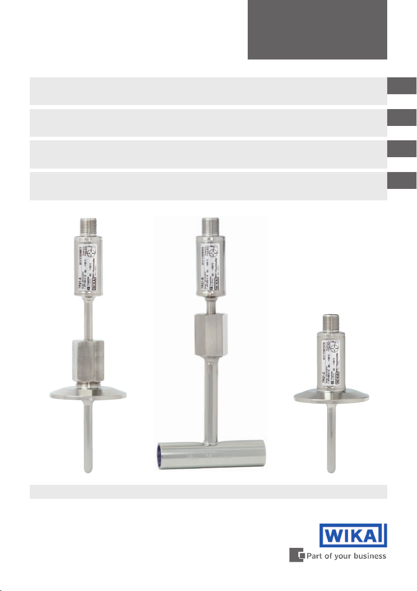
Model TR21-A
Model TR21-B Model TR21-C
Page 2

GB
Operating instructions model TR21
D
Betriebsanleitung Typ TR21
F
Mode d'emploi type TR21
Page 3 - 20
Seite 21 - 38
Page 39 - 56
Manual de instrucciones modelo TR21
E
© 2011 WIKA Alexander Wiegand SE & Co. KG
All rights reserved. / Alle Rechte vorbehalten.
®
is a registered trademark in various countries.
WIKA
®
WIKA
ist eine geschützte Marke in verschiedenen Ländern.
Prior to starting any work, read the operating instructions!
Keep for later use!
Vor Beginn aller Arbeiten Betriebsanleitung lesen!
Zum späteren Gebrauch aufbewahren!
Página 57 - 73
Lire le mode d'emploi avant de commencer toute opération !
A conserver pour une utilisation ultérieure !
¡Leer el manual de instrucciones antes de comenzar cualquier trabajo!
¡Guardar el manual para una eventual consulta!
2
WIKA operating instructions model TR21
14006814.01 05/2011 GB/D/F/E
Page 3

Contents
Contents
1. General information 4
2. Safety 5
3. Specications 8
4. Design and function 10
5. Transport, packaging and storage 13
6. Commissioning, operation 13
7. Maintenance and cleaning 15
8. Faults 16
9. Dismounting, return and disposal 17
10. Accessories 18
Appendix 1: EC declaration of conformity 19
GB
Declarations of conformity can be found online at www.wika.com.
14006814.01 05/2011 GB/D/F/E
WIKA operating instructions model TR21 3
Page 4

1. General information
1. General information
■
The miniature resistance thermometer described in these operating instructions has
GB
been designed and manufactured using state-of-the-art technology. All components
are subject to stringent quality and environmental criteria during production. Our
management systems are certied to ISO 9001 and ISO 14001.
■
These operating instructions contain important information on handling the miniature
resistance thermometer. Working safely requires that all safety instructions and work
instructions are observed.
■
Observe the relevant local accident prevention regulations and general safety regulations
for the miniature resistance thermometer‘s range of use.
■
The operating instructions are part of the product and must be kept in the immediate
vicinity of the miniature resistance thermometer and readily accessible to skilled
personnel at any time.
■
Skilled personnel must have carefully read and understood the operating instructions
prior to beginning any work.
■
The manufacturer‘s liability is void in the case of any damage caused by using the
product contrary to its intended use, non-compliance with these operating instructions,
assignment of insuciently qualied skilled personnel or unauthorised modications to
the miniature resistance thermometer.
■
The general terms and conditions contained in the sales documentation shall apply.
■
Subject to technical modications.
■
Further information:
- Internet address: www.wika.de / www.wika.com
- Relevant data sheet: TE 60.26, TE 60.27, TE 60.28
- Application consultant: Tel.: (+49) 9372/132-0
Fax: (+49) 9372/132-406
E-Mail: info@wika.de
Explanation of symbols
WARNING!
... indicates a potentially dangerous situation that can result in serious injury or
death, if not avoided.
CAUTION!
... indicates a potentially dangerous situation that can result in light injuries or
damage to equipment or the environment, if not avoided.
4 WIKA operating instructions model TR21
14006814.01 05/2011 GB/D/F/E
Page 5
1. General information / 2. Safety
Information
… points out useful tips, recommendations and information for ecient and
trouble-free operation.
WARNING!
... indicates a potentially dangerous situation that can result in burns, caused
by hot surfaces or liquids, if not avoided.
Abbreviations
RTD "Resistance temperature detector"
TC "Thermocouple"
2. Safety
WARNING!
Before installation, commissioning and operation, ensure that the appropriate
miniature resistance thermometer has been selected in terms of measuring
range, design, specic measuring conditions and appropriate wetted parts'
materials (corrosion).
Non-observance can result in serious injury and/or damage to the equipment.
GB
Further important safety instructions can be found in the individual chapters of
these operating instructions.
2.1 Intended use
The TR21 series of resistance thermometers has been developed specically for the
measurement of temperatures in the range of -50 … +250 °C in vessels or pipelines within
sanitary applications. Here, the thermowell is used to protect the temperature sensor from
the process conditions. Furthermore, the detachable connection from the thermowell in the
TR21-A and TR21-B variants enables the removal of the temperature sensor without having
to shut down the process; and thus guards against any damage to the environment or to
personnel which might be caused by escaping process media.
The instrument has been designed and built solely for the intended use described here, and
may only be used accordingly.
The technical specications contained in these operating instructions must be observed.
Improper handling or operation of the instrument outside of its technical specications
requires the instrument to be taken out of service immediately and inspected by an
authorised WIKA service engineer.
14006814.01 05/2011 GB/D/F/E
WIKA operating instructions model TR21 5
Page 6
2. Safety
If the instrument is transported from a cold into a warm environment, the formation of
condensation may result in the instrument malfunctioning. Before putting it back into
operation, wait for the instrument temperature and the room temperature to equalise.
GB
The manufacturer shall not be liable for claims of any type based on operation contrary to
the intended use.
2.2 Personnel qualication
WARNING!
Risk of injury if qualication is insucient!
Improper handling can result in considerable injury and damage to equipment.
■
The activities described in these operating instructions may only be carried
out by skilled personnel who have the qualications described below.
■
Keep unqualied personnel away from hazardous areas.
Skilled personnel
Skilled personnel are understood to be personnel who, based on their technical training,
knowledge of measurement and control technology and on their experience and knowledge
of country-specic regulations, current standards and directives, are capable of carrying out
the work described and of independently recognising potential hazards.
2.3 Special hazards
WARNING!
For hazardous media such as oxygen, acetylene, ammable or toxic gases or
liquids, and refrigeration plants, compressors, etc., in addition to all standard
regulations, the appropriate existing codes or regulations must also be
followed.
WARNING!
Residual media in dismounted instruments can result in a risk to persons, the
environment and equipment. Take sucient precautionary measures.
Do not use this instrument in safety or Emergency Stop devices. Incorrect use
of the instrument can result in injury.
Should a failure occur, aggressive media with extremely high temperature and
under high pressure or vacuum may be present at the instrument.
6 WIKA operating instructions model TR21
14006814.01 05/2011 GB/D/F/E
Page 7
2. Safety
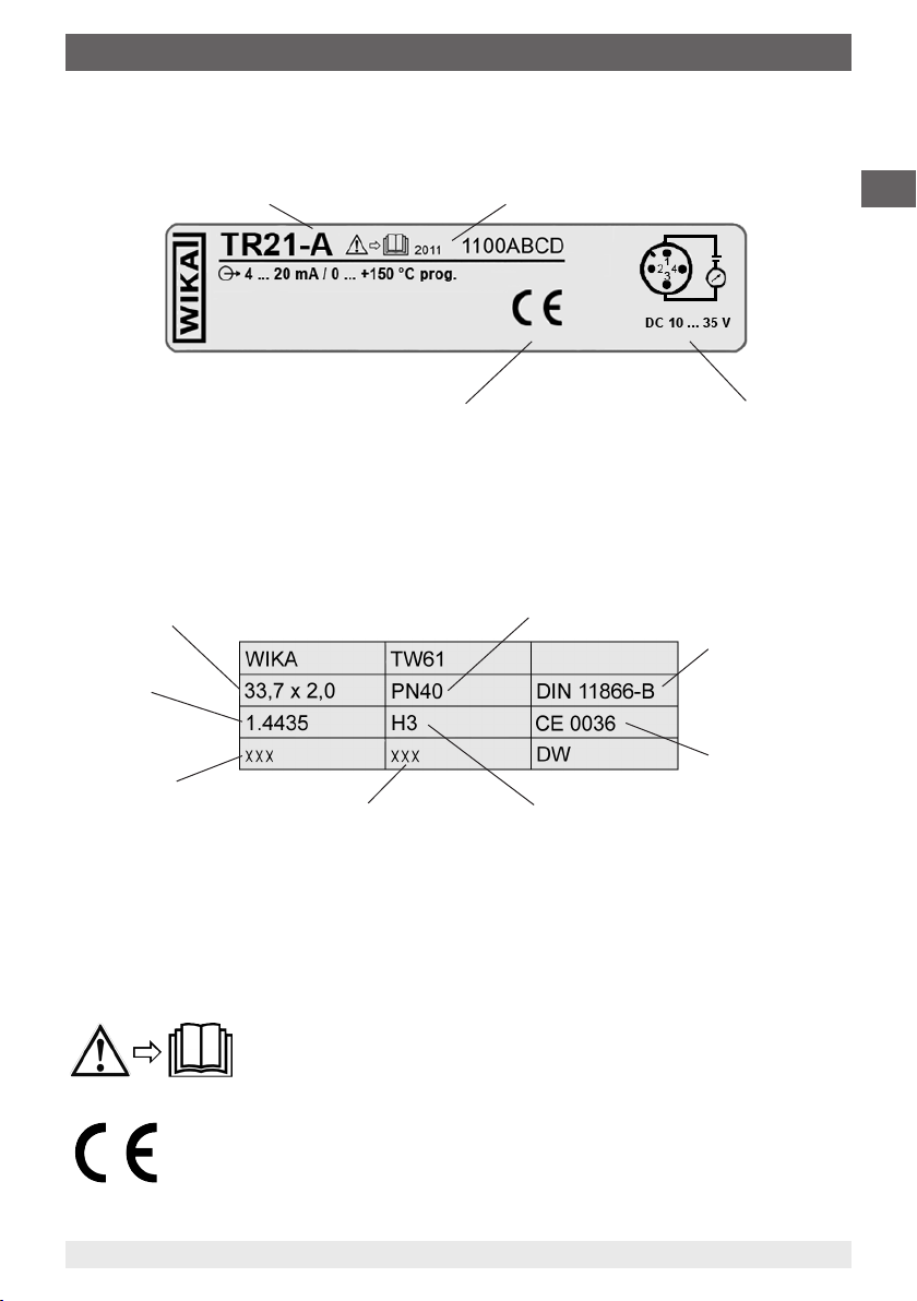
2.4 Labelling / Safety marks
Product label
Model
Year of manufacture
GB
For an explanation of symbols see below
Pin assignment
Thermowell marking
(Example: model TW61 thermowell for model TR21-B resistance thermometer)
Outer diameter x wall thickness (in mm)
Tubular body
material
Material code
(complete assembly)
Identication of the qualied
(for stamping) inspector
max. nominal pressure
Hygiene class
Explanation of symbols
Before mounting and commissioning the instrument, ensure you read
the operating instructions!
Pipe standard
CE-mark
CE, Communauté Européenne
Instruments bearing this mark comply with the relevant European directives.
14006814.01 05/2011 GB/D/F/E
WIKA operating instructions model TR21 7
Page 8

3. Specications
3. Specications
Output signal Pt100
GB
Temperature range Measuring range -50 ... +150 °C, -50 ... +250 °C
Measuring element Pt100 (measuring current: 0.1 ... 1.0 mA) standard measuring resistor
Connection method 3-wire
Sensor tolerance value
2)
per DIN EN 60751
Output signal 4 ... 20 mA
Temperature range Measuring range -50 ... +150 °C, -50 ... +250 °C
Measuring element Pt100 (measuring current: 0.5 mA) standard measuring resistor
Connection method 3-wire
Sensor tolerance value
per DIN EN 60751
Measuring span minimum 20 K, maximum 300 K
Basic conguration
Analogue output 4 ... 20 mA, 2-wire
Measuring deviation
per DIN EN 60770, 23 °C ±5 K
Linearisation linear to temperature per DIN EN 60751
Linearisation error ±0.1 %
Switch-on delay, electrical < 10 ms
Signalling of sensor burnout congurable: NAMUR downscale < 3.6 mA (typically 3 mA)
Sensor short-circuit
Load R
A
Eect of load ± 0.05 % / 100 Ω
Power supply DC 10 ... 35 V
Max. permissible residual ripple 10 % at 24 V / maximum 300 Ω Load
Power supply input protected against reverse polarity
Pt100 (measuring current: 0.1 ... 1.0 mA) face-sensitive measuring
1)
resistor
4-wire
Class B
Class A
Class AA
Pt100 (measuring current: 0.5 mA) face-sensitive measuring resis-
1)
tor
2) 4)
Class B
Class A
Class AA
Measuring range -50 ... +150 °C, -50 ... +250 °C depending on the
selected temperature range, other measuring ranges are adjustable
0.2 % (Transmitter)
5)
4)
NAMUR upscale > 21.0 mA (typically 23 mA)
not congurable, generally NAMUR downscale < 3.6 mA (typically
3 mA)
RA ≤ (UB - 10 V) / 0.023 A with RA in Ω and UB in V
3)
Readings in % refer to the measuring span
For a correct determination of the overall measuring error, both sensor and transmitter measuring deviations have to
be considered.
The small design of the face-sensitive measuring resistors leads to reduced heat dissipation with short insertion lengths.
1)
Available for temperature range -50…+150 °C in Classes A and B.
Face-sensitive measuring resistors are generally used for thermowell insertion lengths smaller than 11 mm.
For detailed specications for Pt100 sensors, see Technical Information IN 00.17 at www.wika.com
2)
The temperature transmitter should therefore be protected from temperatures over 85 °C
3)
For measuring spans smaller than 50 K additional 0.1 K
4)
± 0.2 % for measuring ranges with a lower limit less than 0 °C
5)
8 WIKA operating instructions model TR21
14006814.01 05/2011 GB/D/F/E
Page 9

3. Specications
Power supply eect ± 0.025 % / V
Electromagnetic compatibility
(EMC)
Temperature units congurable °C, °F, K
Info data
Conguration and calibration
data
Electrical connection M12 x 1, 4-pin circular connector
Ambient conditions
Ambient and storage temperature -40 … +85 °C
Case ingress protection
Thermowell
Thermowell model TW22 (models TR21-A, TR21-C)
Surface nish Standard: R
Materials Stainless steel 1.4435 (316L)
Connection to the thermometer Model TR21-A: G 3/8"
Thermowell diameter 6 mm, optional: probe tip reduced to 4.5 mm (from U
Thermowell model TW61 (model TR21-B)
Surface nish Standard: R
Materials Stainless steel 1.4435
Connection to the thermometer G 3/8"
2004/108/EC, EN 61326 emission (Group 1, Class B) and interference Immunity (industrial application)
6)
TAG No., descriptor and message can be stored in transmitter
permanently stored in EEPROM
7)
IP 68
/ IP 69K per IEC 529 / EN 60529
The stated ingress protection only applies when plugged in
using mating connectors that have the appropriate ingress
protection.
< 0.8 µm
Optional: R
R
< 0.4 µm electropolished
a
a
< 0.8 µm electropolished, Ra < 0.4 µm,
a
Model TR21-C: welded
< 0.8 µm
Optional: R
R
< 0.4 µm electropolished
a
a
< 0.8 µm electropolished, Ra < 0.4 µm,
a
> 25 mm)
1
GB
Use resistance thermometers with shielded cable, and ground the shield on at least one end of the lead, if the lines are longer than
6)
30 m or leave the building
1 MWs/ 24 h
7)
Available documentation/certication
■
2.2 Test certicate
■
3.1 Acceptance test certicate
■
DKD certicate
For further specications see WIKA data sheets TE 60.26, TE 60.27 and TE 60.28 as well
as order documentation.
14006814.01 05/2011 GB/D/F/E
WIKA operating instructions model TR21 9
Page 10
4. Design and function
4. Design and function
4.1 Description
GB
The model TR21 miniature resistance thermometers consist of a temperature sensor and a
thermowell with a hygienic process connection.
Any change in the temperature causes a change in the resistance of the Pt100 sensor in
the temperature sensor. This change can be measured directly or can be converted into a
4 ... 20 mA signal proportional to the temperature.
The thermowell is used to adapt the thermometer to the process and protects the sensor
against harsh process conditions. Furthermore, the detachable connection from the
thermowell in the TR21-A and TR21-B variants enables the removal of the temperature
sensor without having to open the process. In this way, any hygienic risk is minimised
and it is possible to calibrate the entire measuring chain (sensor, transmitter if required,
connection cable) on site, without having to disconnect the electrical connection.
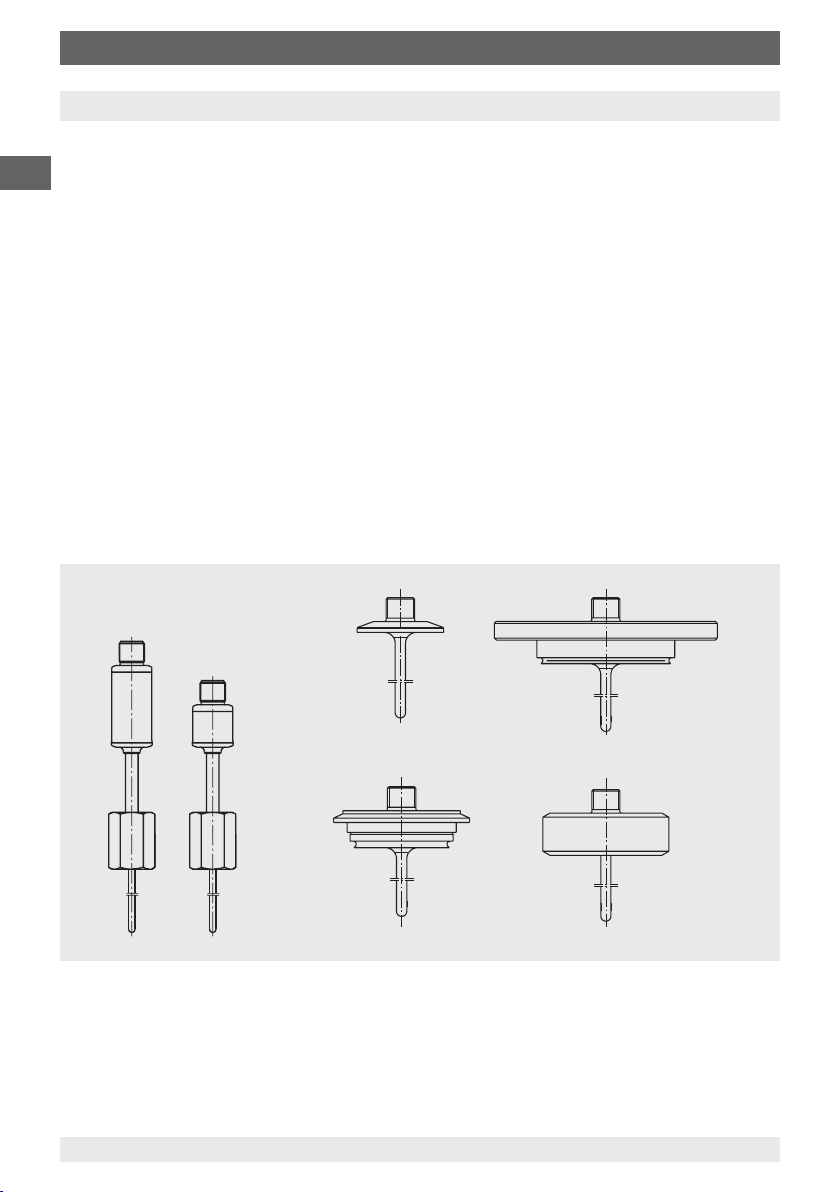
Overview of the process connections/thermowell variants
■
Miniature resistance thermometer model TR21-A with thermowell model TW22
Temperature sensors Thermowell model TW22
Output signal:
4 ... 20 mA
Pt100
Clamp
VARIVENT
10 WIKA operating instructions model TR21
®
BioControl
DIN 11851
®
14006814.01 05/2011 GB/D/F/E
Page 11
4. Design and function
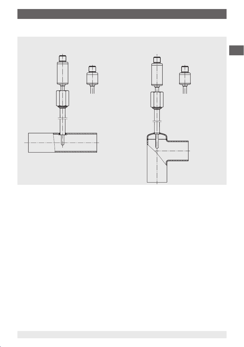
■
Miniature resistance thermometer model TR21-B with thermowell model TW61
Flow-through housing Angular housing
Output signal:
4 ... 20 mA
Pt100
4 ... 20 mA
Pt100
GB
14006814.01 05/2011 GB/D/F/E
WIKA operating instructions model TR21 11
Page 12
4. Design and function
■
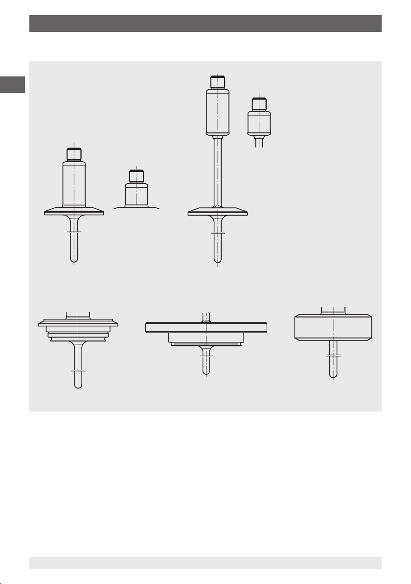
Miniature resistance thermometer model TR21-C
Output signal
:
4 ... 20 mA
GB
Pt100
4 ... 20 mA
Pt100
Clamp
VARIVENT
®
BioControl
®
DIN 11851
4.2 Scope of delivery
Cross-check scope of delivery with the delivery note.
12 WIKA operating instructions model TR21
14006814.01 05/2011 GB/D/F/E
Page 13
5. Transport, packaging and storage / 6. Commissioning, ...
5. Transport, packaging and storage
5.1 Transport
Check the instrument for any damage that may have been caused during transportation.
Obvious damage must be reported immediately.
5.2 Packaging
Do not remove packaging until just before mounting.
Keep the packaging as it will provide optimum protection during transport (e.g. change in
installation site, sending for repair).
5.3 Storage
Permissible conditions at the place of storage:
■
Storage temperature: 0 ... 70 °C
■
Humidity: 35 ... 85 % relative humidity (no condensation)
Avoid exposure to the following factors:
■
Direct sunlight or proximity to hot objects
■
Mechanical vibration, mechanical shock (putting it down hard)
■
Soot, vapour, dust and corrosive gases
■
Potentially explosive environments, ammable atmospheres
WARNING!
Before storing the instrument (following operation), remove any residual media.
This is of particular importance if the medium is hazardous to health, e.g.
caustic, toxic, carcinogenic, radioactive, etc.
GB
6. Commissioning, operation
The connection dimensions of the thermowell must match those of the counterpart on the
process side. Insert the thermowell into the process adapter without forcing or damaging it.
For sealing, choose appropriate seals.
For installation, the appropriate fastenings, such as screws and nuts, must be used; also
using the appropriate mounting torques and tools (e.g. open-ended spanner). The seals
installed must be checked regularly that they are functioning correctly.
The corresponding parts on the process side, the seals and the sealing rings are not
included in the scope of supply.
14006814.01 05/2011 GB/D/F/E
WIKA operating instructions model TR21 13
Page 14
6. Commissioning, operation
Electrical connection
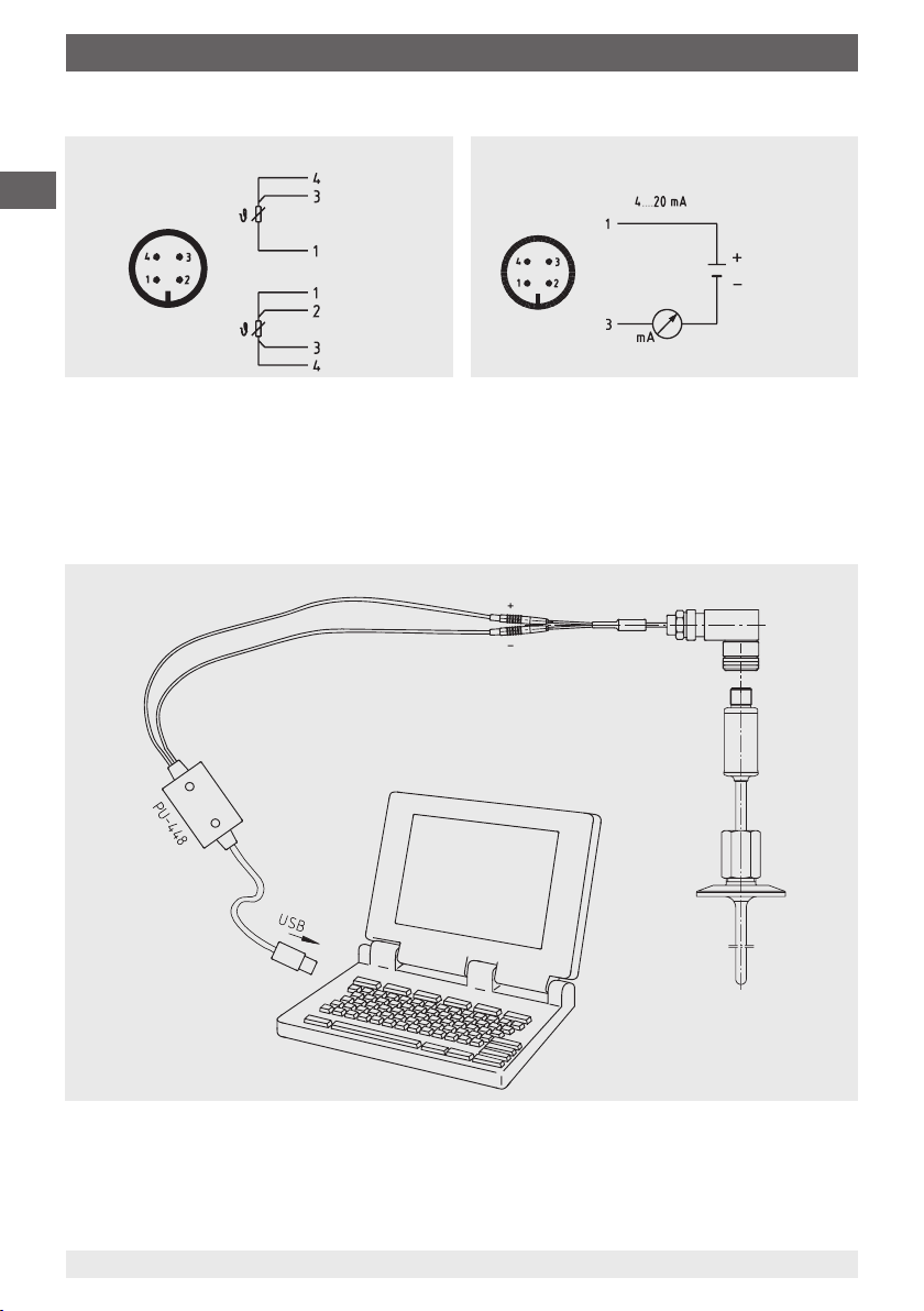
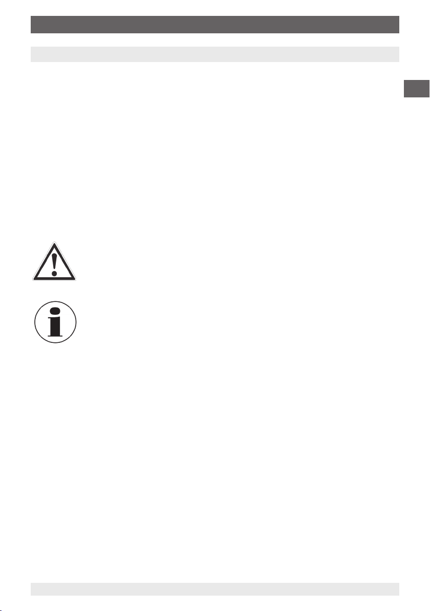
Transmitter (circular connector M12 x 1, 4-pin)Pt100 (circular connector M12 x 1, 4-pin)
GB
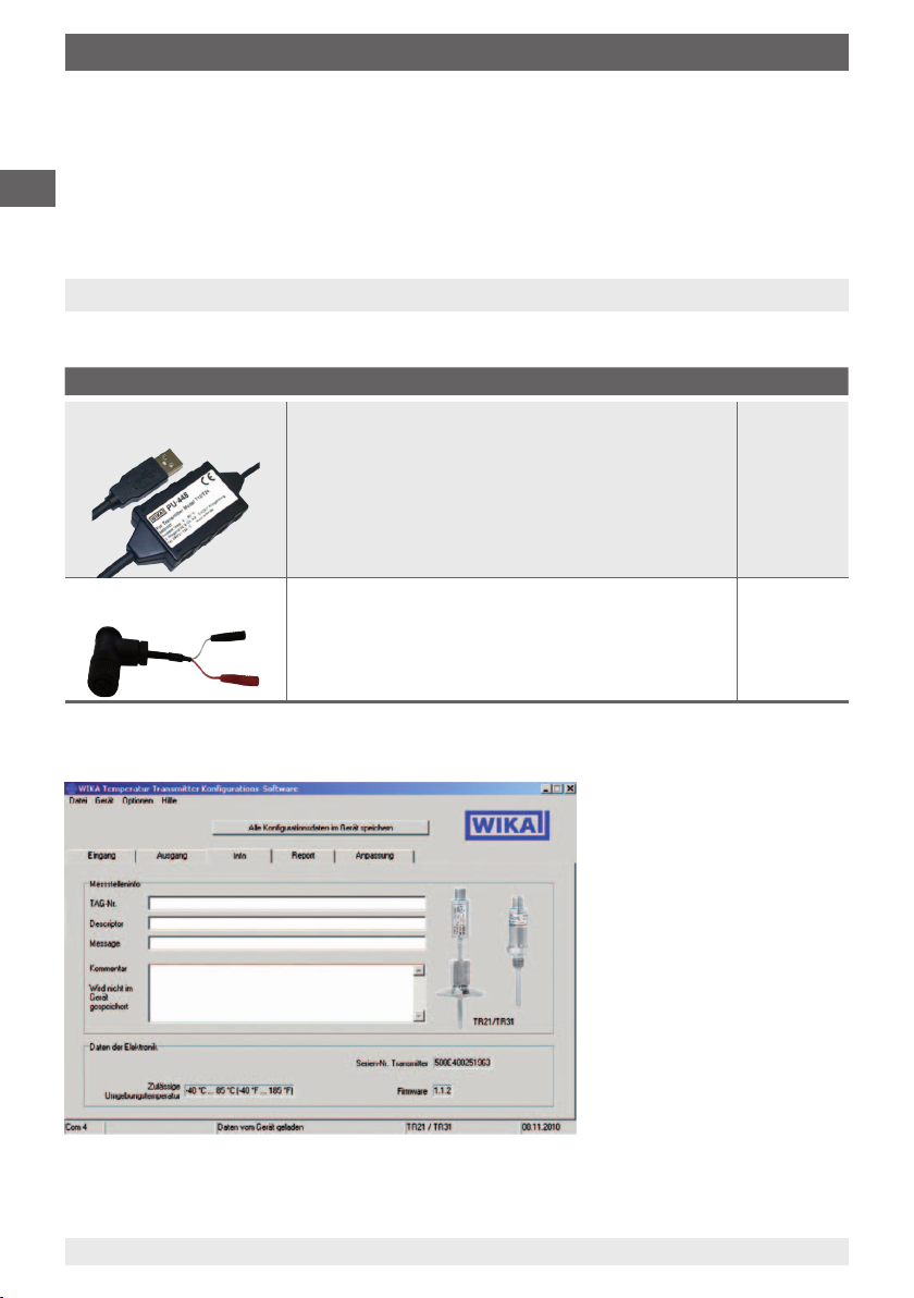
The conguration of the model TR21 miniature resistance thermometer is made via the
WIKA_TT conguration software (multilingual, free download from www.wika.com) and the
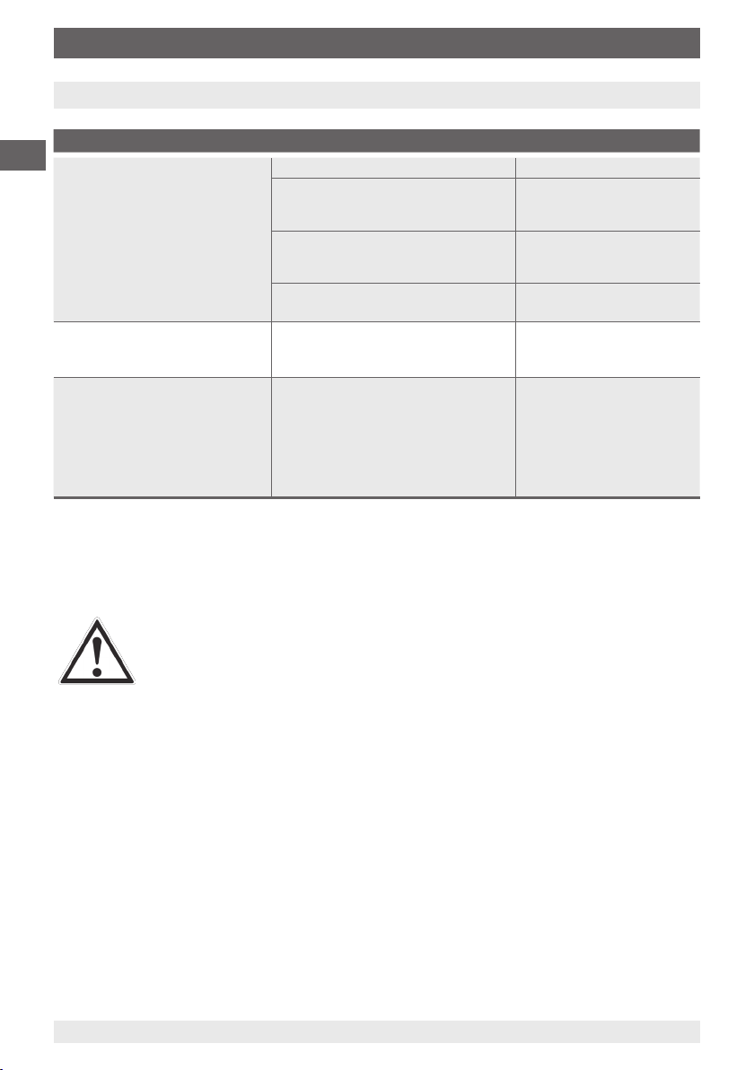
model PU-448 programming unit (see chapter "10. Accessories").
Connecting PU-448 programming unit
Adapter cable PU-448 to M12
DC 10 ... 35 V
TR21
14 WIKA operating instructions model TR21
14004919.01
14006814.01 05/2011 GB/D/F/E
Page 15
7. Maintenance and cleaning
7. Maintenance and cleaning
7.1 Maintenance
The resistance thermometers described here are maintenance-free.
The electronics are completely encapsulated and incorporate no components which could
be repaired or replaced.
In general, thermowells are maintenance-free.
We recommend a visual check of the thermowell for leaks and damages at regular intervals.
Make sure that the seal is in perfect condition!
Repairs should only be carried out by the manufacturer or, following prior consultation, by
correspondingly qualied skilled personnel.
7.2 Cleaning
CAUTION!
■
Wash or clean the dismounted instrument before returning it in order to
protect personnel and the environment from exposure to residual media.
■
Residual media in dismounted instruments can result in a risk to persons,
the environment and equipment. Take sucient precautionary measures.
For information on returning the instrument see chapter "9.2 Return".
GB
14006814.01 05/2011 GB/D/F/E
WIKA operating instructions model TR21 15
Page 16
8. Faults
8. Faults
Faults Causes Measures
GB
Not possible to insert the
temperature sensor into the
thermowell
Leakage of process media
■
at the connection between the
process and the thermowell
■
from the interface between the
thermowell and the sensor
In the case of critical installations, we recommend calculating the harmonic frequency of
the thermowell according to ASME PTC 19.3 or Dittrich/Klotter. This engineering service is
oered by WIKA.
Foreign bodies in the thermowell Remove foreign bodies
Damaged or contaminated
thermowell or temperature sensor
fastening thread
Sensor dimension and those of the
inner diameter of the thermowell do
not match
Thermowell or sensor has been bent
or damaged during installation
Error during installation or defective
seals
Damage, e.g. caused by operating
the thermowell under a resonant
vibration load
Clean or recut the thread
Check order documentation
Return for repair
Check the seal, check the
tightening torques
Safe operation of the
plant can no longer be
guaranteed
(in the worst case, this
might result in a complete
rupture of the thermowell)
CAUTION!
If faults cannot be eliminated by means of the measures listed above, the
instrument must be withdrawn from use immediately, it must be ensured that
there is no longer any pressure and/or signal and they must be prevented from
being inadvertently put back into service.
In this case, contact the manufacturer.
If a return is needed, follow the instructions given in chapter "9.2 Return".
16 WIKA operating instructions model TR21
14006814.01 05/2011 GB/D/F/E
Page 17
9. Dismounting, return and disposal
9. Dismounting, return and disposal
WARNING!
Residual media in dismounted instruments can result in a risk to persons, the
environment and equipment.
Take sucient precautionary measures.
9.1 Dismounting
WARNING!
Risk of burns!
Let the instrument cool down suciently before dismounting!
During dismounting there is a risk of dangerously hot pressure media
escaping.
Only disconnect the resistance thermometer and the thermowell once the system has been
depressurised!
9.2 Return
WARNING!
Absolutely observe the following when shipping the instrument:
All instruments delivered to WIKA must be free from any kind of hazardous
substances (acids, leachate, solutions, etc.).
When returning the instrument, use the original packaging or a suitable transport package.
GB
To avoid damage:
1. Wrap the instrument in an antistatic plastic lm.
2. Place the instrument, along with shock-absorbent material, in the packaging.
Place shock-absorbent material evenly on all sides of the shipping box.
3. If possible, place a bag containing a desiccant inside the packaging.
4. Label the shipment as carriage of a highly sensitive measuring instrument.
Enclose the completed return form with the instrument.
The return form is available on the internet:
www.wika.com / Service / Return
14006814.01 05/2011 GB/D/F/E
WIKA operating instructions model TR21 17
Page 18
9. Dismounting, return and disposal / 10. Accessories
9.3 Disposal
Incorrect disposal can put the environment at risk.
Dispose of instrument components and packaging materials in an environmentally
GB
compatible way and in accordance with the country-specic waste disposal regulations.
10. Accessories
Conguration set
Model Special features Order No.
Programming unit
Model PU-448
■
Easy to use
■
LED statusdisplay
■
Compact version
■
Now no further power supply is needed for either the
programming unit or for the transmitter
■
Measuring the loop current of the model TR21
resistance thermometers is possible
11606304
Adapter cable M12 to
PU-448
Adapter cable for the connection of a resistance
thermometer to the PU-448 programming unit
14003193
Software
WIKA_TT conguration software (multilingual) as a free
download from www.wika.com
18 WIKA operating instructions model TR21
14006814.01 05/2011 GB/D/F/E
Page 19
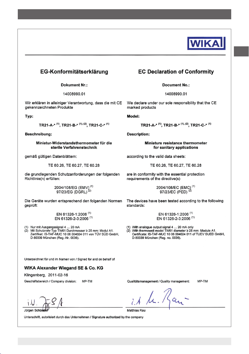
Appendix 1: EC declaration of conformity
GB
14006814.01 05/2011 GB/D/F/E
WIKA operating instructions model TR21 19
Page 20

GB
20 WIKA operating instructions model TR21
14006814.01 05/2011 GB/D/F/E
Page 21
Inhalt
Inhalt
1. Allgemeines 22
2. Sicherheit 23
3. Technische Daten 26
4. Aufbau und Funktion 28
5. Transport, Verpackung und Lagerung 31
6. Inbetriebnahme, Betrieb 31
7. Wartung und Reinigung 33
8. Störungen 34
9. Demontage, Rücksendung und Entsorgung 35
10. Zubehör 36
Anlage 1: EG-Konformitätserklärung 37
Konformitätserklärungen nden Sie online unter www.wika.de.
D
28
14006814.01 05/2011 GB/D/F/E
WIKA Betriebsanleitung Typ TR21 21
Page 22

1. Allgemeines
1. Allgemeines
■
Das in der Betriebsanleitung beschriebene Miniatur-Widerstandsthermometer wird nach
den neuesten Erkenntnissen konstruiert und gefertigt.
Alle Komponenten unterliegen während der Fertigung strengen Qualitäts- und Umweltkriterien. Unsere Managementsysteme sind nach ISO 9001 und ISO 14001 zertiziert.
D
■
Diese Betriebsanleitung gibt wichtige Hinweise zum Umgang mit dem Miniatur-Widerstandsthermometer. Voraussetzung für sicheres Arbeiten ist die Einhaltung aller angegebenen Sicherheitshinweise und Handlungsanweisungen.
■
Die für den Einsatzbereich des Miniatur-Widerstandsthermometers geltenden örtlichen
Unfallverhütungsvorschriften und allgemeinen Sicherheitsbestimmungen einhalten.
■
Die Betriebsanleitung ist Produktbestandteil und muss in unmittelbarer Nähe des
Miniatur-Widerstandsthermometers für das Fachpersonal jederzeit zugänglich
aufbewahrt werden.
■
Das Fachpersonal muss die Betriebsanleitung vor Beginn aller Arbeiten sorgfältig durchgelesen und verstanden haben.
■
Die Haftung des Herstellers erlischt bei Schäden durch bestimmungswidrige Verwendung, Nichtbeachten dieser Betriebsanleitung, Einsatz ungenügend qualizierten
Fachpersonals sowie eigenmächtiger Veränderung am Miniatur-Widerstandsthermometer.
■
Es gelten die allgemeinen Geschäftsbedingungen in den Verkaufsunterlagen.
■
Technische Änderungen vorbehalten.
■
Weitere Informationen:
- Internet-Adresse: www.wika.de / www.wika.com
- zugehöriges Datenblatt: TE 60.26, TE 60.27, TE 60.28
- Anwendungsberater: Tel.: (+49) 9372/132-0
Fax: (+49) 9372/132-406
E-Mail: info@wika.de
Symbolerklärung
WARNUNG!
… weist auf eine möglicherweise gefährliche Situation hin, die zum Tod oder
zu schweren Verletzungen führen kann, wenn sie nicht gemieden wird.
VORSICHT!
… weist auf eine möglicherweise gefährliche Situation hin, die zu
geringfügigen oder leichten Verletzungen bzw. Sach- und Umweltschäden
führen kann, wenn sie nicht gemieden wird.
22 WIKA Betriebsanleitung Typ TR21
14006814.01 05/2011 GB/D/F/E
Page 23
1. Allgemeines / 2. Sicherheit
Information
… hebt nützliche Tipps und Empfehlungen sowie Informationen für einen
ezienten und störungsfreien Betrieb hervor.
WARNUNG!
… weist auf eine möglicherweise gefährliche Situation hin, die durch heiße
Oberächen oder Flüssigkeiten zu Verbrennungen führen kann, wenn sie nicht
gemieden wird.
Abkürzungen
RTD englisch: "Resistance temperature detector"; Widerstandsthermometer
TC englisch: "Thermocouple"; Thermoelement
2. Sicherheit
WARNUNG!
Vor Montage, Inbetriebnahme und Betrieb sicherstellen, dass das richtige
Miniatur-Widerstandsthermometer hinsichtlich Messbereich, Ausführung,
spezischen Messbedingungen und geeignetem messstoberührtem
Werksto (Korrosion) ausgewählt wurde. Bei Nichtbeachten können schwere
Körperverletzungen und/oder Sachschäden auftreten.
D
Weitere wichtige Sicherheitshinweise benden sich in den einzelnen Kapiteln
dieser Betriebsanleitung.
2.1 Bestimmungsgemäße Verwendung
Widerstandsthermometer der Typenreihe TR21 wurden speziell zur Messung von
Temperaturen in Behältern oder Rohrleitungen im Bereich von -50 … +250 °C innerhalb
der sterilen Verfahrenstechnik entwickelt. Dabei dient das Schutzrohr zum Schutz des
Temperaturfühlers gegenüber den Prozessbedingungen. Des Weiteren ermöglicht die
lösbare Verbindung zum Schutzrohr bei den Ausführungen TR21-A und TR21-B den
Ausbau des Temperaturfühlers ohne den Prozess stillzulegen und verhindert Umwelt- oder
Personenschäden durch den Austritt von Prozessmedium.
Das Gerät ist ausschließlich für den hier beschriebenen bestimmungsgemäßen Verwendungszweck konzipiert und konstruiert und darf nur dementsprechend verwendet werden.
Die technischen Spezikationen in dieser Betriebsanleitung sind einzuhalten. Eine
unsachgemäße Handhabung oder ein Betreiben des Gerätes außerhalb der technischen
Spezikationen macht die sofortige Stilllegung und Überprüfung durch einen autorisierten
WIKA-Servicemitarbeiter erforderlich.
14006814.01 05/2011 GB/D/F/E
WIKA Betriebsanleitung Typ TR21 23
Page 24

2. Sicherheit
Wird das Gerät von einer kalten in eine warme Umgebung transportiert, so kann durch
Kondensatbildung eine Störung der Gerätefunktion eintreten. Vor einer erneuten Inbetriebnahme die Angleichung der Gerätetemperatur an die Raumtemperatur abwarten.
Ansprüche jeglicher Art aufgrund von nicht bestimmungsgemäßer Verwendung sind
ausgeschlossen.
D
2.2 Personalqualikation
WARNUNG!
Verletzungsgefahr bei unzureichender Qualikation!
Unsachgemäßer Umgang kann zu erheblichen Personen- und Sachschäden
führen.
■
Die in dieser Betriebsanleitung beschriebenen Tätigkeiten nur durch
Fachpersonal nachfolgend beschriebener Qualikation durchführen lassen.
■
Unqualiziertes Personal von den Gefahrenbereichen fernhalten.
Fachpersonal
Das Fachpersonal ist aufgrund seiner fachlichen Ausbildung, seiner Kenntnisse der Messund Regelungstechnik und seiner Erfahrungen sowie Kenntnis der landesspezischen
Vorschriften, geltenden Normen und Richtlinien in der Lage, die beschriebenen Arbeiten
auszuführen und mögliche Gefahren selbstständig zu erkennen.
2.3 Besondere Gefahren
WARNUNG!
Bei gefährlichen Messstoen wie z. B. Sauersto, Acetylen, brennbaren oder
giftigen Stoen, sowie bei Kälteanlagen, Kompressoren etc. müssen über die
gesamten allgemeinen Regeln hinaus die einschlägigen Vorschriften beachtet
werden.
WARNUNG!
Messstoreste in ausgebauten Geräten können zur Gefährdung von
Personen, Umwelt und Einrichtung führen.
Ausreichende Vorsichtsmaßnahmen ergreifen.
Dieses Gerät nicht in Sicherheits- oder in Not-Aus-Einrichtungen benutzen.
Fehlerhafte Anwendungen des Gerätes können zu Verletzungen führen.
Am Gerät können im Fehlerfall aggressive Medien mit extremer Temperatur
und unter hohem Druck oder Vakuum anliegen.
24 WIKA Betriebsanleitung Typ TR21
14006814.01 05/2011 GB/D/F/E
Page 25

2. Sicherheit
2.4 Beschilderung / Sicherheitskennzeichnungen
Typenschild
Typ
Herstellungsjahr
D
Symbolerklärung siehe unten
Schutzrohrkennzeichnung
(Beispiel: Schutzrohr Typ TW61 bei Widerstandsthermometer Typ TR21-B)
Außendurchmesser x Wandstärke (in mm)
Material
Rohrkörper
Materialcode
(Baugruppe komplett)
Kurzzeichen des Umstempelberechtigten Prüfers
max. Nenndruck
Hygieneklasse
Symbolerklärung
Vor Montage und Inbetriebnahme des Gerätes unbedingt die
Betriebsanleitung lesen!
Anschlussbelegung
Rohrnorm
CE-Kennzeichen
CE, Communauté Européenne
Geräte mit dieser Kennzeichnung stimmen überein mit den zutreenden
europäischen Richtlinien.
14006814.01 05/2011 GB/D/F/E
WIKA Betriebsanleitung Typ TR21 25
Page 26

3. Technische Daten
3. Technische Daten
Ausgangssignal Pt100
Temperaturbereich Messbereich -50 ... +150 °C, -50 ... +250 °C
Messelement Pt100 (Messstrom: 0,1 ... 1,0 mA) Standard-Messwiderstand
D
Schaltungsart 3-Leiter
Grenzabweichung des Messelements
nach DIN EN 60751
Ausgangssignal 4 ... 20 mA
Temperaturbereich Messbereich -50 ... +150 °C, -50 ... +250 °C
Messelement Pt100 (Messstrom: 0,5 mA) Standard-Messwiderstand
Schaltungsart 3-Leiter
Grenzabweichung des Messelements
2) 4)
nach DIN EN 60751
Messspanne minimal 20 K, maximal 300 K
Grundkonguration
Analogausgang 4 ... 20 mA, 2-Draht-Technik
Messabweichung
nach DIN EN 60770, 23 °C ±5 K
Linearisierung Temperaturlinear nach DIN EN 60751
Linearitätsfehler ±0,1 %
Einschaltverzögerung, elektrisch < 10 ms
Signalisierung Fühlerbruch kongurierbar: NAMUR zusteuernd < 3,6 mA (typ. 3 mA)
Fühlerkurzschluss
Bürde R
A
Bürdeneinuss ± 0,05 % / 100 Ω
Hilfsenergie DC 10 ... 35 V
Max. zulässige Restwelligkeit 10 % bei 24 V / maximal 300 Ω Bürde
Hilfsenergieeingang geschützt gegen Verpolung
Hilfsenergieeinuss ± 0,025 % / V
Angaben in % beziehen sich auf die Messspanne
Bei der Ermittlung der Gesamtmessabweichung sind sowohl die Sensor- als auch die Transmitter-Messabweichung
zu berücksichtigen.
Bodenempndliche Messwiderstände führen durch ihre kleine Bauform zu reduzierter Wärmeableitung bei kurzen Einbaulängen.
1)
Verfügbar für den Temperaturbereich -50…+150 °C in den Klassen A und B.
Bei Schutzrohreinbaulängen kleiner 11 mm werden generell bodenempndliche Messwiderstände eingesetzt.
Detaillierte Angaben zu Pt100-Sensoren siehe Technische Information IN 00.17 unter www.wika.de
2)
Der Temperatur-Transmitter ist dabei vor Temperaturen über 85 °C zu schützen
3)
Für Messspannen kleiner 50 K zusätzlich 0,1 K
4)
± 0,2 % bei Messbereichsanfang kleiner 0 °C
5)
26 WIKA Betriebsanleitung Typ TR21
Pt100 (Messstrom: 0,1 ... 1,0 mA) bodenempndlicher
Messwiderstand
4-Leiter
2)
Klasse B
1)
Klasse A
Klasse AA
3)
Pt100 (Messstrom: 0,5 mA) bodenempndlicher
Messwiderstand
1)
Klasse B
Klasse A
Klasse AA
Messbereich -50 ... +150 °C, -50 ... +250 °C je nach gewähltem
Temperaturbereich, andere Messbereiche sind einstellbar
0,2 % (Transmitter)
5)
4)
NAMUR aufsteuernd > 21,0 mA (typisch 23 mA)
nicht kongurierbar, generell NAMUR zusteuernd < 3,6 mA
(typisch 3 mA)
RA ≤ (UB - 10 V) / 0,023 A mit RA in Ω und UB in V
14006814.01 05/2011 GB/D/F/E
Page 27

3. Technische Daten
Elektromagnetische Verträglichkeit
(EMV)
2004/108/EG, EN 61326 Emission (Gruppe 1, Klasse B) und
Störfestigkeit (industrieller Bereich)
6)
Temperatureinheiten kongurierbar °C, °F, K
Info-Daten
Kongurations- und Kalibrierungsdaten
TAG-Nr., Descriptor und Message im Transmitter speicherbar
dauerhaft gespeichert in EEPROM
Elektrischer Anschluss M12 x 1 Rundsteckverbinder 4-polig
Umgebungsbedingungen
Umgebungs- und Lagertemperatur -40 … +85 °C
Gehäuseschutzart
7)
IP 68
/ IP 69K nach IEC 529 / EN 60529
Die angegebenen Schutzarten gelten nur im gesteckten
Zustand mit Leitungssteckern entsprechender Schutzart.
Schutzrohr
Schutzrohr Typ TW22 (Typen TR21-A, TR21-C)
Oberächenrauheit Standard: R
Optional: R
R
< 0,4 µm elektropoliert
a
Werkstoe CrNi-Stahl 1.4435 (316L)
Anschluss zum Thermometer Typ TR21-A: G 3/8"
Typ TR21-C: geschweißt
Schutzrohrdurchmesser 6 mm, optional: Fühlerspitze reduziert auf 4,5 mm
(ab U
Schutzrohr Typ TW61 (Typ TR21-B)
Oberächenrauheit Standard: R
Optional: R
R
< 0,4 µm elektropoliert
a
Werkstoe CrNi-Stahl 1.4435
Anschluss zum Thermometer G 3/8"
< 0,8 µm
a
< 0,8 µm elektropoliert, Ra < 0,4 µm,
a
> 25 mm)
1
< 0,8 µm
a
< 0,8 µm elektropoliert, Ra < 0,4 µm,
a
D
Widerstandsthermometer mit geschirmter Leitung betreiben und den Schirm auf mindestens einer Leitungsseite erden, wenn die
6)
Leitungen länger als 30 m sind oder das Gebäude verlassen
1 MWs/ 24 h
7)
Erhältliche Dokumentationen/Zeugnisse
■
2.2 Werkszeugnis
■
3.1 Abnahmeprüfzeugnis
■
DKD-Zertikat
Weitere technische Daten siehe WIKA Datenblätter TE 60.26, TE 60.27 und TE 60.28 sowie
Bestellunterlagen.
14006814.01 05/2011 GB/D/F/E
WIKA Betriebsanleitung Typ TR21 27
Page 28

4. Aufbau und Funktion
4. Aufbau und Funktion
4.1 Beschreibung
Die Miniatur-Widerstandsthermometer Typ TR21 bestehen aus einem Temperaturfühler und
einem Schutzrohr mit hygienegerechtem Prozessanschluss.
D
Eine Temperaturänderung bewirkt eine Änderung des Widerstandswertes des Pt100
Sensor im Temperaturfühler. Diese Änderung kann direkt abgegrien werden oder
optional über einen Temperatur-Transmitter in temperaturproportionales 4 ... 20 mA-Signal
umgewandelt werden.
Das Schutzrohr dient zur Prozessadaption des Temperaturfühlers und schützt den Sensor
vor rauen Prozessbedingungen. Des Weiteren ermöglicht die lösbare Verbindung zum
Schutzrohr bei den Ausführungen TR21-A und TR21-B den Ausbau des Temperaturfühlers
ohne den Prozess önen zu müssen. Dadurch wird ein Hygienerisiko minimiert und es
ist möglich, die gesamte Messkette (Sensor, ggf. Transmitter, Anschlusskabel) vor Ort zu
kalibrieren, ohne die elektrischen Anschlüsse abzuklemmen.
Übersicht der Prozessanschlüsse/Schutzrohrvarianten
■
Miniatur-Widerstandsthermometer Typ TR21-A mit Schutzrohr Typ TW22
Temperaturfühler Schutzrohr Typ TW22
Ausgangssignal:
4 ... 20 mA
Pt100
Clamp
VARIVENT
28 WIKA Betriebsanleitung Typ TR21
®
BioControl
DIN 11851
®
14006814.01 05/2011 GB/D/F/E
Page 29

4. Aufbau und Funktion
■
Miniatur-Widerstandsthermometer Typ TR21-B mit Schutzrohr Typ TW61
Durchgangsgehäuse Eckgehäuse
Ausgangssignal:
4 ... 20 mA
4 ... 20 mA
Pt100
Pt100
D
14006814.01 05/2011 GB/D/F/E
WIKA Betriebsanleitung Typ TR21 29
Page 30

4. Aufbau und Funktion
■
Miniatur-Widerstandsthermometer Typ TR21-C
Ausgangssignal
D
:
4 ... 20 mA
Pt100
Clamp
4 ... 20 mA
Pt100
VARIVENT
®
BioControl
®
DIN 11851
4.2 Lieferumfang
Lieferumfang mit dem Lieferschein abgleichen.
30 WIKA Betriebsanleitung Typ TR21
14006814.01 05/2011 GB/D/F/E
Page 31

5. Transport, Verpackung, Lagerung / 6. Inbetriebnahme, ...
5. Transport, Verpackung und Lagerung
5.1 Transport
Gerät auf eventuell vorhandene Transportschäden untersuchen.
Oensichtliche Schäden unverzüglich mitteilen.
5.2 Verpackung
Verpackung erst unmittelbar vor der Montage entfernen.
Die Verpackung aufbewahren, denn diese bietet bei einem Transport einen optimalen
Schutz (z. B. wechselnder Einbauort, Reparatursendung).
5.3 Lagerung
Zulässige Bedingungen am Lagerort:
■
Lagertemperatur: 0 ... 70 °C
■
Feuchtigkeit: 35 ... 85 % relative Feuchte (keine Betauung)
Folgende Einüsse vermeiden:
■
Direktes Sonnenlicht oder Nähe zu heißen Gegenständen
■
Mechanische Vibration, mechanischer Schock (hartes Aufstellen)
■
Ruß, Dampf, Staub und korrosive Gase
■
Explosionsgefährdete Umgebung, entzündliche Atmosphären
WARNUNG!
Vor der Einlagerung des Gerätes (nach Betrieb) alle anhaftenden Messstoreste entfernen. Dies ist besonders wichtig, wenn der Messsto gesundheitsgefährdend ist, wie z. B. ätzend, giftig, krebserregend, radioaktiv, usw.
6. Inbetriebnahme, Betrieb
D
Die Anschlussabmessungen des Schutzrohres müssen mit denen des prozessseitigen
Gegenstückes übereinstimmen. Das Schutzrohr ohne Kraftanwendung oder Beschädigung
in die prozessseitige Aufnahme einführen. Zur Abdichtung sind geeignete Dichtungen
auszuwählen.
Zur Montage müssen geeignete Befestigungsteile, wie Schrauben und Muttern, verwendet
und mittels der entsprechenden Anzugsmomente und Werkzeuge (z. B. Gabelschlüssel)
montiert werden. Die verbauten Dichtungen müssen regelmäßig auf eine einwandfreie
Funktion überprüft werden.
Die prozessseitigen Gegenstücke sowie die Dichtungen oder Dichtringe sind nicht im
Lieferumfang enthalten.
14006814.01 05/2011 GB/D/F/E
WIKA Betriebsanleitung Typ TR21 31
Page 32

6. Inbetriebnahme, Betrieb
Elektrischer Anschluss
Transmitter (Rundsteckverbinder 4-polig M12 x 1)Pt100 (Rundsteckverbinder 4-polig M12 x 1)
D
Die Konguration des Miniatur-Widerstandsthermometers Typ TR21 erfolgt mittels
Kongurationssoftware WIKA_TT (mehrsprachig, kostenloser Download unter
www.wika.de) und Programmiereinheit Typ PU-448 (siehe Kapitel „10. Zubehör“).
Programmiereinheit PU-448 anschließen
Adapterkabel PU-448 zu M12
DC 10 ... 35 V
14004919.01
TR21
32 WIKA Betriebsanleitung Typ TR21
14006814.01 05/2011 GB/D/F/E
Page 33

7. Wartung und Reinigung
7. Wartung und Reinigung
7.1 Wartung
Die hier beschriebenen Widerstandsthermometer sind wartungsfrei.
Die Elektronik ist vollständig vergossen und enthält keinerlei Bauteile, welche repariert oder
ausgetauscht werden könnten.
Schutzrohre sind im Allgemeinen wartungsfrei.
Empfohlen wird eine Sichtüberprüfung des Schutzrohres auf Leckagen oder
Beschädigungen in regelmäßigen Intervallen. Insbesondere auf einwandfreie Funktion der
Dichtung achten!
Reparaturen sind ausschließlich vom Hersteller oder nach Absprache durch entsprechend
qualiziertes Fachpersonal durchzuführen.
7.2 Reinigung
VORSICHT!
■
Ausgebautes Gerät vor der Rücksendung spülen bzw. säubern, um
Personen und Umwelt vor Gefährdung durch anhaftende Messstoreste zu
schützen.
■
Messstoreste in ausgebauten Geräten können zur Gefährdung von
Personen, Umwelt und Einrichtung führen.
Ausreichende Vorsichtsmaßnahmen ergreifen.
D
Hinweise zur Rücksendung des Gerätes siehe Kapitel „9.2 Rücksendung“.
14006814.01 05/2011 GB/D/F/E
WIKA Betriebsanleitung Typ TR21 33
Page 34

8. Störungen
8. Störungen
Störungen Ursachen Maßnahmen
Temperaturfühler lässt sich
nicht in das Schutzrohr
einführen
D
Austritt von Prozessmedium
■
ab der Befestigungsebene
Prozess zu Schutzrohr
■
an der Schnittstelle
des Schutzrohres zu
Temperaturfühler oder am
Temperaturfühler selbst
Empfohlen wird bei kritischen Anlagen eine Festigkeitsberechnung des Schutzrohres als
ingenieurstechnische Dienstleistung nach ASME PTC 19.3 oder Dittrich/Klotter.
Fremdkörper im Schutzrohr Fremdkörper entfernen
Beschädigte oder verschmutzte
Befestigungsgewinde von Schutzrohr oder Temperaturfühler
Fühlerabmessung passt nicht zum
Innendurchmesser des Schutzrohes
Schutzrohr oder Fühler wurde bei
Montage verbogen oder beschädigt
Fehler bei der Montage oder fehlerhafte Dichtungen
Defekte, z. B. durch Betrieb des
Schutzrohres im Resonanzfall
Gewinde reinigen oder
nachschneiden
Bestellunterlagen kontrollieren
Zur Reparatur zurück senden
Dichtung überprüfen, Anzugsmomente kontrollieren
Sicherer Betrieb der Anlage
nicht mehr gewährleistet
(führt im schlimmsten Fall zu
einem kompletten Abriss des
Schutzrohres)
VORSICHT!
Können Störungen mit Hilfe der oben aufgeführten Maßnahmen nicht beseitigt
werden, ist das Gerät unverzüglich außer Betrieb zu setzen, sicherzustellen,
dass kein Druck bzw. Signal mehr anliegt und gegen versehentliche
Inbetriebnahme zu schützen.
In diesem Falle Kontakt mit dem Hersteller aufnehmen.
Bei notwendiger Rücksendung die Hinweise unter Kapitel „9.2 Rücksendung“
beachten.
34 WIKA Betriebsanleitung Typ TR21
14006814.01 05/2011 GB/D/F/E
Page 35

9. Demontage, Rücksendung und Entsorgung
9. Demontage, Rücksendung und Entsorgung
WARNUNG!
Messstoreste in ausgebauten Geräten können zur Gefährdung von Personen, Umwelt und Einrichtung führen.
Ausreichende Vorsichtsmaßnahmen ergreifen.
9.1 Demontage
WARNUNG!
Verbrennungsgefahr!
Vor dem Ausbau das Gerät ausreichend abkühlen lassen!
Beim Ausbau besteht Gefahr durch austretende, gefährlich heiße Messstoe.
Widerstandsthermometer und Schutzrohr nur im drucklosen Zustand demontieren!
9.2 Rücksendung
WARNUNG!
Beim Versand des Gerätes unbedingt beachten:
Alle an WIKA gelieferten Geräte müssen frei von Gefahrstoen (Säuren,
Laugen, Lösungen, etc.) sein.
D
Zur Rücksendung des Gerätes die Originalverpackung oder eine geeignete Transportverpackung verwenden.
Um Schäden zu vermeiden:
1. Das Gerät in eine antistatische Plastikfolie einhüllen.
2. Das Gerät mit dem Dämmmaterial in der Verpackung platzieren.
Zu allen Seiten der Transportverpackung gleichmäßig dämmen.
3. Wenn möglich einen Beutel mit Trocknungsmittel der Verpackung beifügen.
4. Sendung als Transport eines hochempndlichen Messgerätes kennzeichnen.
Dem Gerät das Rücksendeformular ausgefüllt beifügen.
Das Rücksendeformular steht im Internet zur Verfügung:
www.wika.de / Service / Rücksendung
14006814.01 05/2011 GB/D/F/E
WIKA Betriebsanleitung Typ TR21 35
Page 36

9. Demontage, Rücksendung und Entsorgung / 10. Zubehör
9.3 Entsorgung
Durch falsche Entsorgung können Gefahren für die Umwelt entstehen.
Gerätekomponenten und Verpackungsmaterialien entsprechend den landesspezischen
Abfallbehandlungs- und Entsorgungsvorschriften umweltgerecht entsorgen.
D
10. Zubehör
Kongurationsset
Typ Besonderheiten Bestell-Nr.
Programmiereinheit
Typ PU-448
■
Einfache Bedienung
■
LED-Status-Anzeigen
■
Kompakte Bauform
■
Keine zusätzliche Spannungsversorgung weder für die
Programmiereinheit noch für den Transmitter notwendig
■
Messung des Schleifenstroms von dem Widerstandsthermometer Typ TR21 möglich
11606304
Adapterkabel M12 zu
PU-448
Adapterkabel zur Anbindung des
Widerstandsthermometers an die Programmiereinheit
Typ PU-448
14003193
Software
Kongurationssoftware WIKA_TT (mehrsprachig) als
kostenloser Download von www.wika.de
36 WIKA Betriebsanleitung Typ TR21
14006814.01 05/2011 GB/D/F/E
Page 37

Anlage 1: EG-Konformitätserklärung
D
14006814.01 05/2011 GB/D/F/E
WIKA Betriebsanleitung Typ TR21 37
Page 38

D
38 WIKA Betriebsanleitung Typ TR21
14006814.01 05/2011 GB/D/F/E
Page 39

Sommaire
Sommaire
1. Généralités 40
2. Sécurité 41
3. Spécications 44
4. Conception et fonction 46
5. Transport, emballage et stockage 49
6. Mise en service, exploitation 49
7. Entretien et nettoyage 51
8. Dysfonctionnements 52
9. Démontage, retour et mise au rebut 53
10. Accessoires 54
Annexe 1 : Déclaration de conformité CE 55
F
Déclarations de conformité se trouvent sur www.wika.fr.
14006814.01 05/2011 GB/D/F/E
WIKA mode d'emploi type TR21 39
Page 40

1. Généralités
1. Généralités
■
La sonde à résistance miniature décrit dans le mode d'emploi est conçu et fabriqué selon
les dernières technologies en vigueur. Tous les composants sont soumis à des critères
de qualité et d'environnement stricts durant la fabrication. Nos systèmes de gestion sont
certiés selon ISO 9001 et ISO 14001.
■
Ce mode d'emploi donne des indications importantes concernant l'utilisation de la sonde
à résistance miniature. Il est possible de travailler en toute sécurité avec ce produit en
F
respectant toutes les consignes de sécurité et d'utilisation.
■
Respecter les prescriptions locales de prévention contre les accidents et les
prescriptions générales de sécurité en vigueur pour le domaine d'application de la sonde
à résistance miniature.
■
Le mode d'emploi fait partie du produit et doit être conservé à proximité immédiate de la
sonde à résistance miniature d'air et accessible à tout moment pour le personnel qualié.
■
Le personnel qualié doit, avant de commencer toute opération, avoir lu soigneusement
et compris le mode d'emploi.
■
La responsabilité du fabricant n'est pas engagée en cas de dommages provoqués par
une utilisation non conforme à l'usage prévu, de non respect de ce mode d'emploi,
d'utilisation de personnel peu qualié de même qu'en cas de modications de la sonde à
résistance miniature.
■
Les conditions générales de vente mentionnées dans les documents de vente
s'appliquent.
■
Sous réserve de modications techniques.
■
Pour obtenir d'autres informations :
- Consulter notre site internet : www.wika.fr
- Fiche technique correspondante : TE 60.26, TE 60.27, TE 60.28
- Conseiller applications : Tel.: (+33) 1 343084-84
Fax: (+33) 1 343084-94
E-Mail: info@wika.fr
Explication des symboles
AVERTISSEMENT !
… indique une situation présentant des risques susceptibles de provoquer la
mort ou des blessures graves si elle n'est pas évitée.
ATTENTION !
… indique une situation potentiellement dangereuse et susceptible de
provoquer de légères blessures ou des dommages matériels et pour
l'environnement si elle n'est pas évitée.
40 WIKA mode d'emploi type TR21
14006814.01 05/2011 GB/D/F/E
Page 41

1. Généralités / 2. Sécurité
Information
… met en exergue les conseils et recommandations utiles de même que les
informations permettant d'assurer un fonctionnement ecace et normal.
ATTENTION !
… indique une situation présentant des risques susceptibles de provoquer des
brûlures dues à des surfaces ou liquides chauds si elle n'est pas évitée.
Abréviations
RTD anglais : "Resistance temperature detector"; les sondes à résistance
TC "Thermocouple"
2. Sécurité
ATTENTION !
Avant le montage, la mise en service et le fonctionnement, s'assurer que
la sonde à résistance miniature a été choisie de façon adéquate, en ce qui
concerne la plage de mesure, la version, les conditions de mesure spéciques
et les pièces en contact avec le uide adéquates (corrosion).
Un non-respect de cette consigne peut entraîner des blessures corporelles
graves et/ou des dégâts matériels.
Vous trouverez d'autres consignes de sécurité dans les sections individuelles
du présent mode d'emploi.
2.1 Utilisation conforme à l'usage prévu
La série TR21 de sondes à résistance a été spécialement développée pour mesurer
des températures dans une plage comprise entre -50 ... +250 °C dans des cuves ou des
tuyauteries au sein d'applications sanitaires. Ici, le doigt de gant est utilisé pour protéger
le capteur de température des conditions de process. Le connecteur détachable du doigt
de gant dans les variantes TR21-A et TR21-B permet en outre le retrait du capteur de
température sans avoir à arrêter le process ; il permet également d'éviter tout dommage
pour l'environnement ou le personnel pouvant résulter d'un écoulement de uide de process.
F
L'instrument est conçu et construit exclusivement pour une utilisation conforme à l'usage
prévu décrit ici et ne doit être utilisé qu'en conséquence.
Les spécications techniques mentionnées dans ce mode d'emploi doivent être
respectées. En cas d'utilisation inadéquate ou de fonctionnement de l'instrument en dehors
des spécications techniques, un arrêt et contrôle doivent être immédiatement eectués
par un collaborateur autorisé du service de WIKA.
14006814.01 05/2011 GB/D/F/E
WIKA mode d'emploi type TR21 41
Page 42

2. Sécurité
Si l'instrument est transporté d'un environnement froid dans un environnement chaud,
la formation de condensation peut provoquer un dysfonctionnement fonctionnel de
l'instrument. Il est nécessaire d'attendre que la température de l'instrument se soit adaptée à
la température ambiante avant une nouvelle mise en service.
Aucune réclamation ne peut être recevable en cas d'utilisation non conforme à l'usage
prévu.
2.2 Qualication du personnel
F
Personnel qualié
Le personnel qualié est, en raison de sa formation spécialisée, de ses connaissances
dans le domaine de la technique de mesure et de régulation et de ses expériences de
même que de sa connaissance des prescriptions nationales des normes et directives en
vigueur, en mesure d‘eectuer les travaux décrits et de reconnaître automatiquement les
dangers potentiels.
AVERTISSEMENT !
Danger de blessure en cas de qualication insusante!
Une utilisation non conforme peut entraîner d'importants dommages corporels
et matériels.
■
Les opérations décrites dans ce mode d'emploi ne doivent être eectuées
que par un personnel ayant la qualication décrite ci-après.
■
Tenir le personnel non qualié à lécart des zones dangereuses.
2.3 Dangers particuliers
AVERTISSEMENT !
Dans le cas de uides de mesure dangereux comme notamment l'oxygène,
l'acétylène, les substances combustibles ou toxiques, ainsi que dans le
cas d'installations de réfrigération, de compresseurs etc., les directives
appropriées existantes doivent être observées en plus de l'ensemble des
règles générales.
ATTENTION !
Les restes de uides se trouvant dans les instruments démontés peuvent
mettre en danger les personnes, l'environnement ainsi que l'installation.
Prendre des mesures de sécurité susantes.
Ne pas utiliser cet instrument dans des dispositifs de sécurité ou d'arrêt
d‘urgence. Une utilisation incorrecte de l'instrument peut occasionner des
blessures.
En cas d'erreur, des uides agressifs peuvent être disponibles à une
température extrême et sous une pression élevée ou sous vide au niveau du
capteur de pression.
42 WIKA mode d'emploi type TR21
14006814.01 05/2011 GB/D/F/E
Page 43

2. Sécurité
2.4 Etiquetage / Marquages de sécurité
Plaque signalétique
Type
Explication des symboles, voir en bas
Année de fabrication
Marquage de gaine
(Exemple: gaine type TW61 pour sonde à résistance type TR21-B)
Diamètre extérieur x épaisseur (en mm)
Matériau du
corps tubulaire
Code du matériau
(assemblage complet)
Identication de l'inspecteur
qualié (pour l'homologation)
Pression nominale max.
Classe hygiénique
F
Conguration du raccordement
Tuyauterie standard
Marquage CE
Explication des symboles
Lire impérativement le mode d'emploi avant le montage et la mise en
service de l'instrument !
CE, Communauté Européenne
Les instruments avec ce marquage sont conformes aux directives
européennes pertinentes.
14006814.01 05/2011 GB/D/F/E
WIKA mode d'emploi type TR21 43
Page 44

3. Spécications
3. Spécications
Signal de sortie Pt100
Plage de température Etendue de mesure -50 ... +150 °C, -50 ... +250 °C
Elément de mesure Pt100 (courant de mesure : 0,1 ... 1,0 mA) résistance standard de mesure
Type de raccordement 3 ls
Précision du capteur
F
selon DIN EN 60751
Signal de sortie 4 ... 20 mA
Plage de température Etendue de mesure -50 ... +150 °C, -50 ... +250 °C
Elément de mesure Pt100 (courant de mesure : 0,5 mA) résistance standard de mesure
Type de raccordement 3 ls
Précision du capteur
selon DIN EN 60751
Intervalle de mesure minimum 20 K, maximum 300 K
Conguration de base
Sortie analogique 4 ... 20 mA, 2 ls
Ecart de mesure selon
DIN EN 60770, 23 °C ±5 K
Linéarisation linéaire par rapport à la température selon DIN EN 60751
Linéarisation d'erreur ±0,1 %
Retard au démarrage,
électrique
Signalement de la
surchaue du capteur
Court-circuit capteur Non congurable, en général bas d'échelle NAMUR < 3,6 mA (typ. 3 mA)
Charge R
Eet de charge ± 0,05 % / 100 Ω
Alimentation 10 ... 35 VDC
Ondulation résiduelle max.
admissible
Les indications en % se rapportent à la plage de mesure
Pour une détermination correcte de l'erreur de mesure globale, il convient de prendre en compte à la fois les
déviations de mesure du capteur et du transmetteur.
1)
2) Pour obtenir des spécications détaillées sur les capteurs Pt100, voir l'information technique IN 00.17 sur www.wika.fr.
3) C'est pourquoi le transmetteur de température doit être protégé des températures supérieures à 85 °C
4) Pour plages de mesure inférieures à 50 K plus 0,1 K
5) ± 0,2 % pour les plages de mesure avec une limite inférieure en-dessous de 0 °C
44 WIKA mode d'emploi type TR21
A
La conception ne des résistances de mesure à sensibilité de surface permet de réduire la dissipation de chaleur grâce à des
longueurs d'insertion courtes.
Disponible pour une plage de température comprise entre -50 ... +150 °C dans les classes A et B.
Les résistances mesurant une sensibilité de surface sont généralement utilisées pour les doigts de gant dont la longueur d'insertion
est inférieure à 11 mm.
Pt100 (courant de mesure : 0,1 ... 1,0 mA) résistance de mesure à
sensibilité de surface
4 ls
2)
Classe B
1)
Classe A
Classe AA
3)
Pt100 (courant de mesure : 0,5 mA) résistance de mesure à sensibilité
de surface
2) 4)
Classe B
1)
Classe A
Classe AA
Etendue de mesure -50 ... +150 °C, -50 ... +250 °C en fonction de la plage
de température sélectionnée, d'autres étendues de mesure sont réglables
0,2 % (transmetteur)
5)
4)
< 10 ms
Congurable : bas d'échelle NAMUR < 3,6 mA (typiquement 3 mA)
Haut d'échelle NAMUR > 21,0 mA (typiquement 23 mA)
RA ≤ (UB - 10 V) / 0,023 A avec RA en Ω et UB en V
10 % à 24 V / charge 300 Ω maxi
14006814.01 05/2011 GB/D/F/E
Page 45

3. Spécications
Entrée alimentation
protégée contre l'inversion de polarité
électrique
Eet de l'alimentation
± 0,025 % / V
électrique
Compatibilité
électromagnétique (CEM)
2004/108/CE, EN 61326 émission (groupe 1, classe B) et immunité
d'interférence (application industrielle)
6)
Unités de température congurables °C, °F, K
Données d'info
N° identication, description et message peuvent être stockés dans le
transmetteur
Données de conguration
stockées en permanence dans l'EEPROM
et d'étalonnage
Raccordement électrique connecteur M12 x 1, 4 plots
Conditions ambiantes
Température ambiante et température
de stockage
Indice de protection du boîtier IP 68
-40 … +85 °C
7)
/ IP 69K selon IEC 529 / EN 60529
L'indice de protection mentionné n’est valable que lorsque
le contre-connecteur auquel est raccordé la sonde de temp.
possède également l'indice de protection requis.
Gaine
Gaine type TW22 (types TR21-A, TR21-C)
Etat de surface Standard : R
En option : R
Matériaux Acier inox 1.4435 (316L)
Raccord au thermomètre Type TR21-A: G 3/8"
Type TR21-C: soudé
Diamètre gaine 6 mm, en option : rétrein à 4,5 mm (à partir de U
Gaine type TW61 (type TR21-B)
Etat de surface Standard :
En option : R
Matériaux Acier inox 1.4435
Raccord au thermomètre G 3/8"
Utiliser des sondes à résistance avec un câble blindé, et mettre le blindage à la terre à une extrémité du l de sortie au moins, si les
6)
lignes sont longues de plus de 30 m ou sortent du bâtiment.
1 MWs/ 24 h
7)
< 0,8 µm
a
< 0,8 µm électropoli, Ra < 0,4 µm,
a
R
< 0,4 µm électropoli
a
R
< 0,8 µm
a
< 0,8 µm électropoli, Ra < 0,4 µm,
a
R
< 0,4 µm électropoli
a
> 25 mm)
1
F
Documentation / Certication disponible
■
Certicat d'essai 2.2
■
Certicat d'essai de mise en service 3.1
■
Certicat d'étalonnage DKD
Pour les autres caractéristiques techniques, voir che technique WIKA TE 60.26, TE 60.27
et TE 60.28 et les documents de commande.
14006814.01 05/2011 GB/D/F/E
WIKA mode d'emploi type TR21 45
Page 46

4. Conception et fonction
4. Conception et fonction
4.1 Description
La sonde à résistance miniature TR21 est constituée d'un capteur de température et d'un
doigt de gant avec un raccord process hygiénique.
Tout changement de la température provoque une modication dans la résistance du
capteur Pt100 dans le capteur de température. Cette modication peut être mesurée
directement ou convertie en un signal 4 ... 20 mA proportionnel à la température.
F
Le doigt de gant est utilisé pour adapter la sonde de température au process et pour
protéger le capteur des conditions de process diciles. Le raccord détachable du doigt
de gant dans les variantes TR21-A et TR21-B permet en outre le retrait du capteur de
température sans avoir à interrompre le process. Ainsi, les risques en matière d'hygiène
sont minimisés et il est possible de calibrer l'intégralité de la chaîne de mesure (capteur,
transmetteur (si nécessaire), câble de connexion) sur site, sans avoir à débrancher le
raccordement électrique.
Vue générale des raccords process et versions de doigt de gant/gaines
■
Sonde à résistance miniature type TR21-A, avec gaine type TW22
Capteur de température Gaine type TW22
Signal de sortie :
4 ... 20 mA
Pt100
Clamp
VARIVENT
46 WIKA mode d'emploi type TR21
®
BioControl
DIN 11851
®
14006814.01 05/2011 GB/D/F/E
Page 47

4. Conception et fonction
■
Sonde à résistance miniature type TR21-B, avec gaine type TW61
Montage en ligne Montage angulaire
Signal de sortie :
4 ... 20 mA
4 ... 20 mA
Pt100
Pt100
F
14006814.01 05/2011 GB/D/F/E
WIKA mode d'emploi type TR21 47
Page 48

4. Conception et fonction
■
Sonde à résistance miniature type TR21-C
Signal de sortie :
4 ... 20 mA
F
Pt100
Clamp
4 ... 20 mA
Pt100
VARIVENT
®
BioControl
®
DIN 11851
4.2 Détail de la livraison
Comparer le détail de la livraison avec le bordereau de livraison.
48 WIKA mode d'emploi type TR21
14006814.01 05/2011 GB/D/F/E
Page 49

5. Transport, emballage et stockage / 6. Mise en service, ...
5. Transport, emballage et stockage
5.1 Transport
Vérier s'il existe des dégâts sur l'instrument liés au transport.
Communiquer immédiatement les dégâts constatés.
5.2 Emballage
N'enlever l'emballage qu'avant le montage.
Conserver l'emballage, celui-ci ore, lors d'un transport, une protection optimale (par ex.
changement de lieu d'utilisation, renvoi pour réparation).
5.3 Stockage
Conditions admissibles sur le lieu de stockage :
■
Température de stockage : 0 ... 70 °C
■
Humidité : 35 ... 85 % humidité relative (pas de formation de rosée)
Eviter les inuences suivantes :
■
Lumière solaire directe ou proximité d'objets chauds
■
Vibrations mécaniques, chocs mécaniques (mouvements brusques en le posant)
■
Suie, vapeur, poussière et gaz corrosifs
■
Environnement présentant des risques d'explosion, atmosphères inammables
F
ATTENTION !
Enlever tous les restes de uides adhérents avant l'entreposage de
l'instrument (après le fonctionnement). Ceci est particulièrement important
lorsque le uide représente un danger pour la santé, comme p. ex. des
substances corrosives, toxiques, cancérogènes, radioactives etc.
6. Mise en service, exploitation
Les dimensions du connecteur du doigt de gant doivent correspondre à celles de la partie
opposée côté process. Insérer le doigt de gant dans l'adaptateur de process sans forcer et
sans endommager l'une ou l'autre partie. Pour l'étanchéité, utiliser des joints adaptés.
Pour l'installation, utiliser des xations appropriées telles que des vis et des écrous, des outils
adaptés (par ex. clé à fourche) et respecter les couples de montage correspondants. Les
joints mis en place doivent être contrôlés régulièrement pour vérier qu'ils sont en bon état.
Les pièces correspondantes côté process, les joints et les bagues d'étanchéité ne font pas
partie du volume de livraison.
14006814.01 05/2011 GB/D/F/E
WIKA mode d'emploi type TR21 49
Page 50

6. Mise en service, exploitation
Raccordement électrique
Pt100 (connecteur circulaire M12 x 1, 4 plots)
F
La conguration de la sonde à résistance miniature TR21 est réalisée via le logiciel de
conguration WIKA_TT (multilingue, téléchargement gratuit à l'adresse www.wika.fr) et
l'unité de programmation PU-448 (voir chapitre "10. Accessoires").
Raccordement de l'unité de programmation PU-448
Transmitter (connecteur circulaire M12 x 1, 4 plots)
Câble d'adaptateur PU-448 vers M12
DC 10 ... 35 V
TR21
50 WIKA mode d'emploi type TR21
14004919.01
14006814.01 05/2011 GB/D/F/E
Page 51

7. Entretien et nettoyage
7. Entretien et nettoyage
7.1 Entretien
Les sondes à résistance décrits ici sont sans entretien.
L'électronique est complètement encapsulée et ne comporte aucun composant pouvant
être réparé ou remplacé.
En général, les doigts de gant ne nécessitent aucune maintenance.
Nous recommandons de procéder à un contrôle visuel des doigts de gant à la recherche de
fuites et de détériorations à intervalles réguliers. Assurez-vous que les joints sont en parfait
état !
Toute réparation doit être conée exclusivement au fabricant ou, après consultation
préalable de Wika, à un personnel qualié.
7.2 Nettoyage
ATTENTION !
■
Laver ou nettoyer l'instrument démonté avant de le renvoyer pour protéger
le personnel et l'environnement contre l'exposition à des restes de uides.
■
Les restes de uides se trouvant dans les instruments démontés peuvent
mettre en danger les personnes, l'environnement ainsi que l'installation.
Prendre des mesures de sécurité susantes.
F
Indications concernant le retour de l'instrument, voir chapitre "9.2 Retour".
14006814.01 05/2011 GB/D/F/E
WIKA mode d'emploi type TR21 51
Page 52

8. Dysfonctionnements
8. Dysfonctionnements
Dysfonctionnements Raisons Mesures
Impossible d'insérer le capteur
de température dans le doigt de
gant.
F
Fuite de uide de process
■
au niveau de la jonction entre
le process et le doigt de gant
■
de l'interface entre le doigt de
gant et le capteur.
Présence de corps étrangers dans
le doigt de gant
Filetage de xation du doigt de
gant ou du capteur de température
endommagé ou contaminé
Les dimensions du capteur et celles
du diamètre intérieur du doigt de
gant ne correspondent pas.
Le doigt de gant ou le capteur a
été tordu ou endommagé pendant
l'installation.
Erreur pendant l'installation ou joints
défectueux
Détérioration, due par ex. à
l'utilisation du doigt de gant soumis
à une charge de vibrations résonnantes.
Dans le cas d'installations critiques, nous recommandons le calcul de la fréquence
harmonique du doigt de gant selon ASME PTC 19.3 ou Dittrich/Klotter. Ce service
d'ingénierie est proposé par WIKA.
Retirer les corps étrangers.
Nettoyer ou réaliser un
nouveau letage.
Vérier les documents relatifs
à la commande.
Retour pour réparation
Vérier le joint et contrôler les
couples de serrage
Le fonctionnement en toute
sécurité de l'usine ne peut
plus être garanti
(dans le pire des cas, il peut
en résulter une rupture totale
du doigt de gant)
ATTENTION !
Si des dysfonctionnements ne peuvent pas être éliminés à l'aide des mesures
indiquées ci-dessus, l'instrument doit être immédiatement retiré, il faut
s'assurer qu'aucune pression et/ou qu'aucun signal n'est plus disponible et le
protéger contre toute mise en service involontaire.
Contacter dans ce cas le fabricant.
S'il est nécessaire de retourner l'instrument au fabricant, respecter les
indications mentionnées au chapitre "9.2 Retour".
52 WIKA mode d'emploi type TR21
14006814.01 05/2011 GB/D/F/E
Page 53

9. Démontage, retour et mise au rebut
9. Démontage, retour et mise au rebut
AVERTISSEMENT !
Les restes de uides se trouvant dans les instruments démontés peuvent
mettre en danger les personnes, l'environnement ainsi que l'installation.
Prendre des mesures de sécurité susantes.
9.1 Démontage
AVERTISSEMENT !
Danger de brûlure !
Avant le démontage, laisser refroidir susamment l'instrument !
Danger de brûlure lié à la sortie de uides dangereux chauds.
Déconnecter la sonde à résistance et le doigt de gant uniquement une fois que le système
a été mis hors pression.
9.2 Retour
AVERTISSEMENT !
Il faut absolument observer les consignes suivantes lors de l'expédition de
l'instrument :
Tous les instruments envoyés à WIKA doivent être exempts de toute
substance dangereuse (acides, lixiviats, solutions, etc.).
Pour retourner l'instrument, utiliser l'emballage original ou un emballage adapté pour le
transport.
Pour éviter des dommages :
1. Emballer l'instrument dans une feuille de plastique antistatique.
2. Placer l'instrument avec le matériau isolant dans l'emballage.
Isoler de manière uniforme tous les côtés de l'emballage de transport.
3. Mettre si possible un sachet absorbeur d'humidité dans l'emballage.
4. Indiquer lors de l'envoi qu'il s'agit d'un instrument de mesure très sensible à transporter.
F
Joindre le formulaire de retour rempli à l'instrument.
Le formulaire de retour est disponible sur Internet :
www.wika.fr / Services / Retour
14006814.01 05/2011 GB/D/F/E
WIKA mode d'emploi type TR21 53
Page 54

9. Démontage, retour et mise au rebut / 10. Accessoires
9.3 Mise au rebut
Une mise au rebut inadéquate peut entraîner des dangers pour l'environnement.
Eliminer les composants des instruments et les matériaux d'emballage conformément
aux prescriptions nationales pour le traitement et l'élimination des déchets et aux lois de
protection de l'environnement en vigueur.
10. Accessoires
F
Kit de conguration
Type Particularités N° cde
Unité de programmation
Type PU-448
Câble d'adaptateur M12
vers PU-448
■
Facile à utiliser
■
Achage d'état par DEL
■
Version compacte
■
Maintenant, plus besoin d'alimentation électrique
supplémentaire pour l'unité de programmation ou pour
le transmetteur.
■
Il est possible de mesurer le courant de ligne des
sondes à résistance de type TR21.
Câble d'adaptateur pour le raccordement d'une sonde à
résistance à l'unité de programmation PU-448
11606304
14003193
Logiciel
Logiciel de conguration WIKA_TT (multilingue)
téléchargeable gratuitement sur www.wika.fr
54 WIKA mode d'emploi type TR21
14006814.01 05/2011 GB/D/F/E
Page 55

Annexe 1 : Déclaration de conformité CE
F
14006814.01 05/2011 GB/D/F/E
WIKA mode d'emploi type TR21 55
Page 56

F
56 WIKA mode d'emploi type TR21
14006814.01 05/2011 GB/D/F/E
Page 57

Contenido
Contenido
1. Información general 58
2. Seguridad 59
3. Datos técnicos 62
4. Diseño y función 64
5. Transporte, embalaje y almacenamiento 67
6. Puesta en servicio, funcionamiento 67
7. Mantenimiento y limpieza 69
8. Fallos 70
9. Desmontaje, devolución y eliminación 71
10. Accesorios 72
Anexo 1: Declaración de conformidad CE 73
Declaraciones de conformidad puede encontrar en www.wika.es.
E
14006814.01 05/2011 GB/D/F/E
WIKA manual de instrucciones modelo TR21 57
Page 58

1. Información general
1. Información general
■
La termorresistencia miniatura descrita en el manual de instrucciones está construida
y fabricada según los conocimientos actuales. Todos los componentes están sujetos a
estrictos criterios de calidad y medio ambiente durante la producción. Nuestros sistemas
de gestión están certicados según ISO 9001 e ISO 14001.
■
Este manual de instrucciones proporciona indicaciones importantes sobre del manejo
de la termorresistencia miniatura. Para un trabajo seguro, es imprescindible cumplir con
todas las instrucciones de seguridad y manejo indicadas.
■
Observar las normativas sobre prevención de accidentes y las normas de seguridad en
vigor en el lugar de utilización de la termorresistencia miniatura.
E
■
El manual de instrucciones es una parte integrante del instrumento y debe guardarse
en la proximidad del mismo para que el personal especializado pueda consultarlo en
cualquier momento.
■
El personal especializado debe haber leído y entendido el manual de instrucciones antes
de comenzar cualquier trabajo.
■
El fabricante queda exento de cualquier responsabilidad en caso de daños causados
por un uso no conforme a la nalidad prevista, la inobservancia del presente manual
de instrucciones, un manejo por personal insucientemente cualicado así como una
modicación no autorizada de la termorresistencia miniatura.
■
Se aplican las condiciones generales de venta incluidas en la documentación de venta.
■
Modicaciones técnicas reservadas.
■
Para obtener más informaciones consultar:
- Página web: www.wika.es
- Hoja técnica correspondiente: TE 60.26, TE 60.27, TE 60.28
- Servicio técnico:
Tel.: (+34) 933 938-630
Fax: (+34) 933 938-666
E-Mail: info@wika.es
Explicación de símbolos
¡ADVERTENCIA!
... indica una situación probablemente peligrosa que pueda causar la muerte o
lesiones graves si no se evita.
¡CUIDADO!
... indica una situación probablemente peligrosa que pueda causar lesiones
leves o medianas o daños materiales y medioambientales si no se evita.
58 WIKA manual de instrucciones modelo TR21
14006814.01 05/2011 GB/D/F/E
Page 59

1. Información general / 2. Seguridad
Información
... destaca consejos y recomendaciones útiles así como informaciones para
una utilización ecaz y libre de fallos.
¡ADVERTENCIA!
... indica una situación probablemente peligrosa que pueda causar
quemaduras debido a supercies o líquidos calientes, si no se evita.
Abreviaturas
RTD inglés: "Resistance temperature detector"; termorresistencia
TC inglés: "Thermocouple"; termopar
2. Seguridad
¡ADVERTENCIA!
Antes del montaje, la puesta en servicio y el funcionamiento asegurarse
de que se haya seleccionado la termorresistencia miniatura adecuada con
respecto a rango de medida, versión, condiciones de medición especícas y
material adecuado para el contacto con el medio (corrosión).
Riesgo de lesiones graves y/o daños materiales en caso de inobservancia.
E
Los distintos capítulos de este manual de instrucciones contienen otras
importantes indicaciones de seguridad.
2.1 Uso conforme a lo previsto
Las termorresistencias de la serie TR21 han sido desarrolladas especialmente para medir
la temperatura en el rango de -50 ... +250 °C dentro de contenedores o de la tubería en
procesos estériles. La vaina protege el sensor de temperatura frente a las condiciones
del proceso. La conexión de los modelos TR21-A y TR21-B que puede desacoplarse de
la vaina permite además desmontar el sensor de temperatura sin necesidad de parada
técnica del proceso y previene así los daños medioambientales o personales causados por
el escape del medio.
El instrumento ha sido diseñado y construido únicamente para la nalidad aquí descrita y
debe utilizarse en conformidad a la misma.
Cumplir las especicaciones técnicas de este manual de instrucciones. Un manejo no
apropiado o una utilización del instrumento no conforme a las especicaciones técnicas
requiere la inmediata puesta fuera de servicio y la comprobación por parte de un técnico
autorizado por WIKA.
14006814.01 05/2011 GB/D/F/E
WIKA manual de instrucciones modelo TR21 59
Page 60

2. Seguridad
Si se transporta el instrumento de un ambiente frío a uno caliente, puede producirse un
fallo de funcionamiento en el mismo. En tal caso, hay que esperar que la temperatura
del instrumento se adapte a la temperatura ambiente antes de ponerlo nuevamente en
funcionamiento.
No se admite ninguna reclamación debido a un manejo no adecuado.
2.2 Cualicación del personal
¡ADVERTENCIA!
¡Riesgo de lesiones debido a una insuciente cualicación!
E
Personal especializado
Debido a su formación profesional, a sus conocimientos de la técnica de regulación
y medición así como a su experiencia y su conocimiento de las normativas, normas y
directivas vigentes en el país de utilización el personal especializado es capaz de ejecutar
los trabajos descritos y reconocer posibles peligros por sí solo.
Un manejo no adecuado puede causar considerables daños personales y
materiales.
■
Las actividades descritas en este manual de instrucciones deben realizarse
únicamente por personal especializado con la consiguiente cualicación.
■
Mantener alejado a personal no cualicado de las zonas peligrosas.
2.3 Riesgos especícos
¡ADVERTENCIA!
En el caso de sustancias peligrosas a medir, como p. ej. oxígeno, acetileno,
sustancias inamables o tóxicas, así como en instalaciones de refrigeración,
compresores, etc., deben observarse en cada caso, además de todas las
reglas generales, las disposiciones pertinentes.
¡ADVERTENCIA!
Restos de medios en instrumentos desmontados pueden causar riesgos para
personas, medio ambiente e instalación.
Tomar adecuadas medidas de precaución.
No utilizar este instrumento en sistemas de seguridad o dispositivos de
parada de emergencia. Una utilización incorrecta del instrumento puede
causar lesiones.
En caso de fallo es posible que haya medios agresivos con temperaturas
extremas o de bajo presión o que haya un vacío en el instrumento.
60 WIKA manual de instrucciones modelo TR21
14006814.01 05/2011 GB/D/F/E
Page 61

2. Seguridad
2.4 Rótulos / Marcajes de seguridad
Placa indicadora de modelo
Modelo
Explicación de símbolos véase abajo
Año de fabricación
Identicación de la vaina
(Ejemplo: vaina modelo TW61 en termorresistencia modelo TR21-B)
Diámetro exterior x grosor de la pared (en mm)
Material de
la tubería
Código del material
(grupo completo)
Identicación del inspector
con autorización de estampar
máx. presión nominal
Clase de higiene
Detalles del conexionado
E
Normativa de la
tubería
Marcado CE
Explicación de símbolos
¡Es absolutamente necesario leer el manual de instrucciones antes
del montaje y la puesta en servicio del instrumento!
CE, Communauté Européenne
Los instrumentos con este marcaje cumplen las directivas europeas
aplicables.
14006814.01 05/2011 GB/D/F/E
WIKA manual de instrucciones modelo TR21 61
Page 62

3. Datos técnicos
3. Datos técnicos
Señal de salida Pt100
Rango de temperatura Rango de medida -50 ... +150 °C, -50 ... +250 °C
Elemento de medición
Tipo de conexionado 3 hilos
Desviación límite del elemento de
2)
medida
Señal de salida 4 ... 20 mA
E
según DIN EN 60751
Rango de temperatura Rango de medida -50 ... +150 °C, -50 ... +250 °C
Elemento de medición
Tipo de conexionado 3 hilos
Desviación límite del elemento de
2) 4)
medida
según DIN EN 60751
Span de medida mín. 20 K, máx. 300 K
Conguración básica Rango de medida -50 ... +150 °C, -50 ... +250 °C
Salida analógica 4 … 20 mA, técnica de 2 hilos
Desviación
según DIN EN 60770, 23 °C ±5 K
Linealización Linealización de temperatura según DIN EN 60751
Error de linealización ±0,1 %
Retardo de conexión, eléctrico < 10 ms
Señalización de la ruptura de la sonda Congurable: NAMUR mínimo < 3,6 mA (típico 3 mA)
Cortocircuito de la sonda
Carga RA RA ≤ (UB - 10 V) / 0,023 A con RA en Ω y UB in V
Inuencia de la carga ± 0,05 % / 100 Ω
Alimentación auxiliar DC 10 ... 35 V
Ondulación residual máx. admisible 10 % con 24 V / carga máx. de 300 Ω
Entrada de la energía auxiliar Protección contra polaridad inversa
Pt100 (corriente de medición: 0,1 ... 1,0 mA) sensor estándar
Pt100 (corriente de medición: 0,1 ... 1,0 mA) sensor plano
4 hilos
Clase B
Clase A
Clase AA
Pt100 (corriente de medición: 0,5 mA) sensor estándar
Pt100 (corriente de medición: 0,5 mA) sensor plano
Clase B
Clase A
Clase AA
dependiendo del rango de temperatura seleccionado, otros
rangos de medida pueden ajustarse
0,2 % (transmisor)
5)
4)
NAMUR máximo > 21,0 mA (típico 23 mA)
No congurable: generalmente NAMUR mínimo < 3,6 mA
(típico 3 mA)
1)
1)
Indicaciones en % están relacionados al span de medición
Para la determinación de la desviación total de medición deben considerarse la desviación de medición del
sensor y la del transmisor.
El diseño compacto del sensor plano conlleva a disminuir la disipación de calor con longitudes de inserciones cortas.
1)
Disponible para rangos de temperaturas -50 … +150 °C para clases A y B.
Los sensores planos se aplican normalmente para vainas con longitudes de inserción inferiores de 11 mm.
Para consultar más detalles acerca de las sondas Pt100 véase la información técnica IN 00.17 en www.wika.es.
2)
Proteger el transmisor de temperatura de temperaturas superiores a 85 °C.
3)
Para márgenes de medición inferiores a 50 K adicionalmente 0,1 K
4)
± 0,2 % para valor inicial de rango de medida inferior a 0 °C
5)
62 WIKA manual de instrucciones modelo TR21
14006814.01 05/2011 GB/D/F/E
Page 63

3. Datos técnicos
Inuencia de la alimentación auxiliar ± 0,025 % / V
Compatibilidad electromagnética
(CEM)
Unidades de temperatura congurables: °C, °F, °K
Datos informativos Nº TAG, descriptor y mensaje pueden guardarse en el
Datos de conguración y calibración Permanentemente guardados en EEPROM
Conexión eléctrica Conector circular M12 x 1 4-pin
Condiciones externas
Temperatura ambiental y de almacenamiento -40 … +85 °C
Protección de la caja
Vaina
Vaina modelo TW22 (modelos TR21-A, TR21-C)
Rugosidad de la supercie Estándar: R
Materiales Acero inoxidable 1.4435 (316L)
Conexión al termómetro Modelo TR21-A: G 3/8"
Diámetro de la vaina 6 mm, opción: punta del sensor reducida a 4,5 mm (a partir
Vaina modelo TW61 (modelo TR21-B)
Rugosidad de la supercie Estándar: R
Materiales Acero inoxidable 1.4435
Conexión al termómetro G 3/8"
2004/108/CE, EN 61326 Emisión (Grupo 1, Clase B) y
resistencia a interferencias (ámbito industrial)
6)
transmisor
7)
IP 68
/ IP 69K según IEC 529 / EN 60529
El tipo de protección indicado sólo es válido en
estado conectado con conectores según el modo de
protección correspondiente.
< 0,8 µm
Opción: R
R
< 0,4 µm electropulida
a
a
< 0,8 µm electropulida, Ra < 0,4 µm,
a
Modelo TR21-C: soldada
de U
> 25 mm)
1
< 0,8 µm
Opción: R
R
< 0,4 µm electropulida
a
a
< 0,8 µm electropulida, Ra < 0,4 µm,
a
E
Utilizar la termorresistencia con un cable blindado y poner a tierra el blindaje en un lado del cable como mínimo si los cables tienen
6)
una longitud superior a 30 m o si salen del edicio.
7) 1 MWs/ 24 h
Documentación/certicados disponible
■
2.2 Certicado de prueba
■
3.1 Certicado de inspección
■
Certicado DKD
Para más datos técnicos véanse las hojas técnicas de WIKA TE 60.26, TE 60.27 y TE 60.28
y la documentación de pedido.
14006814.01 05/2011 GB/D/F/E
WIKA manual de instrucciones modelo TR21 63
Page 64

4. Diseño y función
4. Diseño y función
4.1 Descripción
La termorresistencia miniatura, modelo TR21, está compuesta por un sensor de
temperatura y una vaina con conexión higiénica.
Un cambio de la temperatura produce un cambio del valor de resistencia de la sonda
Pt100 en el sensor de temperatura. Este cambio puede consultarse directamente o
convertirse opcionalmente mediante un transmisor de temperatura en una señal 4 ... 20 mA
proporcional a la temperatura.
E
La vaina adapta el sensor de temperatura al proceso y lo protege frente a las condiciones
adversas del mismo. La conexión de los modelos TR21-A y TR21-B puede desacoplarse
de la vaina y permite desmontar el sensor de temperatura sin necesidad de abrir abrir el
proceso. De este modo se minimiza el riesgo de falta de higiene, y es posible calibrar toda
la cadena de medición (sensor, transmisor, si hay, cable de conexión) in situ sin tener que
desconectar las conexiones eléctricas.
Vista general de las conexiones/variantes de vaina
■
Termorresistencia miniatura modelo TR21-A con vaina modelo TW22
Sensor de temperatura Vaina modelo TW22
Señal de salida:
4 ... 20 mA
Pt100
Clamp
VARIVENT
64 WIKA manual de instrucciones modelo TR21
®
BioControl
DIN 11851
®
14006814.01 05/2011 GB/D/F/E
Page 65

4. Diseño y función
■
Termorresistencia miniatura modelo TR21-B con vaina modelo TW61
Caja de paso Caja angular
Señal de salida:
4 ... 20 mA
4 ... 20 mA
Pt100
Pt100
E
14006814.01 05/2011 GB/D/F/E
WIKA manual de instrucciones modelo TR21 65
Page 66

4. Diseño y función
■
Termorresistencia miniatura modelo TR21-C
Señal de salida:
E
:
4 ... 20 mA
Pt100
Clamp
4 ... 20 mA
Pt100
VARIVENT
®
BioControl
®
DIN 11851
4.2 Volumen de suministro
Comparar mediante el albarán si se han entregado todas las piezas.
66 WIKA manual de instrucciones modelo TR21
14006814.01 05/2011 GB/D/F/E
Page 67

5. Transporte, embalaje, almacenamiento / 6. Puesta en ...
5. Transporte, embalaje y almacenamiento
5.1 Transporte
Comprobar si el instrumento presenta eventuales daños causados en el transporte.
Noticar de inmediato cualquier daño evidente.
5.2 Embalaje
No quitar el embalaje hasta justo antes del montaje.
Guardar el embalaje ya que es la protección ideal durante el transporte (por ejemplo si el
lugar de instalación cambia o si se envía el instrumento para posibles reparaciones).
5.3 Almacenamiento
Condiciones admisibles en el lugar de almacenamiento:
■
Temperatura de almacenamiento: 0 ... 70 °C
■
Humedad: 35 ... 85 % de humedad relativa (sin rocío)
Evitar lo siguiente:
■
Luz solar directa o proximidad a objetos calientes
■
Vibración mecánica, impacto mecánico (colocación brusca)
■
Hollín, vapor, polvo y gases corrosivos
■
Entorno potencialmente explosivo, atmósferas inamables
¡ADVERTENCIA!
Antes de almacenar el instrumento (después del funcionamiento), eliminar
todos los restos de medios adherentes. Esto es especialmente importante
cuando el medio es nocivo para la salud, como p. ej. cáustico, tóxico,
cancerígeno, radioactivo, etc.
6. Puesta en servicio, funcionamiento
Las dimensiones de la conexión de la vaina tienen que coincidir con el equivalente del
proceso. La vaina debe montarse en el alojamiento del proceso sin tener que aplicar fuerza
o sin causar daños. Seleccionar juntas aptas para el sellado.
E
Para el montaje, utilizar piezas de jación adecuadas, como p. ej. tornillos y tuercas, y
apretarlos con sus pares de apriete respectivos utilizando la herramienta adecuada (p.
ej. llave de boca). Comprobar periodicamente el funcionamiento correcto de las juntas
aplicadas.
Las contrapiezas en el lado del proceso así como las juntas y los anillos obturadores no
están incluidos en la entrega.
14006814.01 05/2011 GB/D/F/E
WIKA manual de instrucciones modelo TR21 67
Page 68

6. Puesta en servicio, funcionamiento
Conexión eléctrica
Transmisor (conector circular de 4 polos M12 x 1)Pt100 (conector circular de 4 polos M12 x 1)
E
La termorresistencia miniatura TR21 se congura mediante el software de conguración
WIKA_TT (en varios idiomas; descarga gratuita de www.wika.es) y la unidad de
programación PU-448 (véase el capítulo "10. Accesorios").
Conectar la unidad de programación PU-448
Cable adaptador PU-448 a M12
DC 10 ... 35 V
TR21
68 WIKA manual de instrucciones modelo TR21
14004919.01
14006814.01 05/2011 GB/D/F/E
Page 69

7. Mantenimiento y limpieza
7. Mantenimiento y limpieza
7.1 Mantenimiento
Las termorresistencias miniatura que se describen aquí no requieren mantenimiento.
Los componentes electrónicos están completamente encapsulados y no incorporan
componentes de ningún tipo para el intercambio o para la reparación.
Normalmente las vainas de protección no requieren mantenimiento.
Recomendamos inspeccionar visualmente las vainas de protección a intervalos regulares
por si presentan fugas o daños.
¡Es particularmente importante que la obturación esté intacta!
Todas las reparaciones solamente las debe efectuar el fabricante o, a convenir, personal
debidamente instruido y calicado.
7.2 Limpieza
¡CUIDADO!
■
Una vez desmontado el instrumento se debe enjuagar y limpiar antes
de devolverlo para proteger a las personas y el medio ambiente contra
residuos del medio de medición.
■
Restos de medios en instrumentos desmontados pueden causar riesgos
para personas, medio ambiente e instalación. Tomar adecuadas medidas
de precaución.
E
Véase el capítulo "9.2 Devolución" para obtener más información acerca de la
devolución del instrumento.
14006814.01 05/2011 GB/D/F/E
WIKA manual de instrucciones modelo TR21 69
Page 70

8. Fallos
8. Fallos
Fallos Causas Medidas
El sensor de temperatura no se
puede introducir en la vaina.
E
El medio de proceso escapa
■
en el punto de jación del
proceso a la vaina
■
en el punto de contacto
entre la vaina y el sensor de
temperatura o en el sensor
mismo
En caso de instalaciones críticas recomendamos un análisis de la resistencia mecánica
de la vaina de protección según ASME PTC 19.3 ó Dittrich/Klotter. WIKA les ofrece este
servicio.
Hay cuerpos extraños en la vaina Eliminar los cuerpos extraños
La rosca de jación de la vaina o del
sensor de temperatura está dañada
o sucia
Las dimensiones del sensor y el
diámetro interior de la vaina no
coinciden
La vaina y el sensor fue doblada o
dañada durante el montaje
Montaje incorrecto o juntas
defectuosas
Defectos, p. ej. por la utilización de la
vaina en el caso de resonancia
Limpiar o lubricar la rosca
Controlar la documentación
de pedido
Enviar la vaina para que se
repare
Controlar la junta, controlar el
par de apriete
El funcionamiento seguro
de la instalación ya no está
garantizado
(en el peor de los casos
puede causar la ruptura
completa de la vaina)
¡CUIDADO!
Si no es posible eliminar los fallos mediante las medidas arriba mencionadas,
poner inmediatamente el instrumento fuera de servicio; asegurarse de que ya
no esté sometido a ninguna presión o señal y proteger el instrumento contra
una puesta en servicio accidental o erronea.
En este caso ponerse en contacto con el fabricante.
Si una devolución del instrumento es necesaria, observar las indicaciones en
el capítulo "9.2 Devolución".
70 WIKA manual de instrucciones modelo TR21
14006814.01 05/2011 GB/D/F/E
Page 71

9. Desmontaje, devolución y eliminación
9. Desmontaje, devolución y eliminación
¡ADVERTENCIA!
Restos de medios en instrumentos desmontados pueden causar riesgos para
personas, medio ambiente e instalación.
Tomar adecuadas medidas de precaución.
9.1 Desmontaje
¡ADVERTENCIA!
¡Riesgo de quemaduras!
¡Dejar enfriar el instrumento lo suciente antes de desmontarlo!
Peligro debido a medios muy calientes que se escapan durante el desmontaje.
¡Desmontar la termorresistencia y vaina sólo si no están sometidas a presión!
9.2 Devolución
¡ADVERTENCIA!
Es imprescindible observar lo siguiente para el envío del instrumento:
Todos los instrumentos enviados a WIKA deben estar libres de sustancias
peligrosas (ácidos, lejías, soluciones, etc.).
E
Utilizar el embalaje original o un embalaje adecuado para la devolución del instrumento.
Para evitar daños:
1. Envolver el instrumento en un lm de plástico antiestático.
2. Colocar el instrumento junto con el material aislante en el embalaje.
Aislar uniformemente todos los lados del embalaje de transporte.
3. Si es posible, adjuntar una bolsa con secante.
4. Aplicar un marcaje que indique que se trata de un envío de un instrumento de medición
altamente sensible.
Rellenar el formulario de devolución y adjuntarlo al instrumento.
El formulario de devolución está disponible en internet:
www.wika.es / Servicio / Devoluciones
14006814.01 05/2011 GB/D/F/E
WIKA manual de instrucciones modelo TR21 71
Page 72

9. Desmontaje, devolución y eliminación / 10. Accesorios
9.3 Eliminación de residuos
Una eliminación incorrecta puede provocar peligros para el medio ambiente.
Eliminar los componentes de los instrumentos y los materiales de embalaje conforme a
los reglamentos relativos al tratamiento de residuos y eliminación vigentes en el país de
utilización.
10. Accesorios
Kit de conguración
Modelo Características N° de pedido
E
Unidad de programación
Modelo PU-448
Cable adaptador
M12 a PU-448
■
Fácil manejo
■
Indicadores de estado por LED
■
Diseño compacto
■
No se necesita ninguna alimentación de corriente
adicional ni para la unidad de programación ni
para el transmisor
■
Posibilidad de medir la corriente de bucle del
transmisor modelo T24 y de los termómetros
modelos TR21, TR30 y TR31
Cable adaptador para conectar la termorresistencia
modelo TR21-A a la unidad de programación
modelo PU-448
11606304
14003193
Software
El software de conguración WIKA_TT (en varios idiomas)
puede descargarse gratuitamente desde www.wika.es
72 WIKA manual de instrucciones modelo TR21
14006814.01 05/2011 GB/D/F/E
Page 73

Anexo 1: Declaración de conformidad CE
E
14006814.01 05/2011 GB/D/F/E
WIKA manual de instrucciones modelo TR21 73
Page 74

WIKA global
Europe
Austria
WIKA Messgerätevertrieb
Ursula Wiegand GmbH & Co. KG
1230 Vienna
Tel. (+43) 1 86916-31
Fax: (+43) 1 86916-34
E-Mail: info@wika.at
www.wika.at
Benelux
WIKA Benelux
6101 WX Echt
Tel. (+31) 475 535-500
Fax: (+31) 475 535-446
E-Mail: info@wika.nl
www.wika.nl
Bulgaria
WIKA Bulgaria EOOD
Bul. "Al. Stamboliiski" 205
1309 Soa
Tel. (+359) 2 82138-10
Fax: (+359) 2 82138-13
E-Mail: t.antonov@wika.bg
Croatia
WIKA Croatia d.o.o.
Hrastovicka 19
10250 Zagreb-Lucko
Tel. (+385) 1 6531034
Fax: (+385) 1 6531357
E-Mail: info@wika.hr
www.wika.hr
Finland
WIKA Finland Oy
00210 Helsinki
Tel. (+358) 9-682 49 20
Fax: (+358) 9-682 49 270
E-Mail: info@wika.
www.wika.
France
WIKA Instruments s.a.r.l.
95610 Eragny-sur-Oise
Tel. (+33) 1 343084-84
Fax: (+33) 1 343084-94
E-Mail: info@wika.fr
www.wika.fr
Germany
WIKA Alexander Wiegand
SE & Co. KG
63911 Klingenberg
Tel. (+49) 9372 132-0
Fax: (+49) 9372 132-406
E-Mail: info@wika.de
www.wika.de
Italy
WIKA Italia Srl & C. Sas
20020 Arese (Milano)
Tel. (+39) 02 9386-11
Fax: (+39) 02 9386-174
E-Mail: info@wika.it
www.wika.it
Poland
WIKA Polska S.A.
87-800 Wloclawek
Tel. (+48) 542 3011-00
Fax: (+48) 542 3011-01
E-Mail: info@wikapolska.pl
www.wikapolska.pl
Romania
WIKA Instruments Romania
S.R.L.
Bucuresti, Sector 5
Calea Rahovei Nr. 266-268
Corp 61, Etaj 1
78202 Bucharest
Tel. (+40) 21 4048327
Fax: (+40) 21 4563137
E-Mail: m.anghel@wika.ro
Russia
ZAO WIKA MERA
127015 Moscow
Tel. (+7) 495-648 01 80
Fax: (+7) 495-648 01 81
E-Mail: info@wika.ru
www.wika.ru
Serbia
WIKA Merna Tehnika d.o.o.
Sime Solaje 15
11060 Belgrade
Tel. (+381) 11 2763722
Fax: (+381) 11 753674
E-Mail: info@wika.co.yu
www.wika.co.yu
Spain
Instrumentos WIKA, S.A.
C/Josep Carner, 11-17
08205 Sabadell (Barcelona)
Tel. (+34) 933 938630
Fax: (+34) 933 938666
E-Mail: info@wika.es
www.wika.es
Switzerland
MANOMETER AG
6285 Hitzkirch
Tel. (+41) 41 91972-72
Fax: (+41) 41 91972-73
E-Mail: info@manometer.ch
www.manometer.ch
Turkey
WIKA Instruments Istanbul
Basinc ve Sicaklik Ölcme
Cihazlari
Ith. Ihr. ve Tic. Ltd. Sti.
Bayraktar Bulvari No. 21
34775 Yukari Dudullu - Istanbul
Tel. (+90) 216 41590-66
Fax: (+90) 216 41590-97
E-Mail: info@wika.com.tr
www.wika.com.tr
Ukraine
WIKA Pribor GmbH
83016 Donetsk
Tel. (+38) 062 34534-16
Fax: (+38) 062 34534-17
E-Mail: info@wika.ua
www.wika.ua
United Kingdom
WIKA Instruments Ltd
Merstham, Redhill RH13LG
Tel. (+44) 1737 644-008
Fax: (+44) 1737 644-403
E-Mail: info@wika.co.uk
www.wika.co.uk
74 WIKA operating instructions model TR21
14006814.01 05/2011 GB/D/F/E
Page 75

WIKA global
North America
Canada
WIKA Instruments Ltd.
Head Oce
Edmonton, Alberta, T6N 1C8
Tel. (+1) 780 46370-35
Fax: (+1) 780 46200-17
E-Mail: info@wika.ca
www.wika.ca
Mexico
Instrumentos WIKA Mexico S.A.
de C.V.
01210 Mexico D.F.
Tel. (+52) 55 55466329
E-Mail: ventas@wika.com
www.wika.com.mx
USA
WIKA Instrument Corporation
Lawrenceville, GA 30043
Tel. (+1) 770 5138200
Fax: (+1) 770 3385118
E-Mail: info@wika.com
www.wika.com
WIKA Instrument Corporation
Houston Facility
950 Hall Court
Deer Park, TX 77536
Tel. (+1) 713-475 0022
Fax (+1) 713-475 0011
E-mail: info@wikahouston.com
www.wika.com
Mensor Corporation
201 Barnes Drive
San Marcos, TX 78666
Tel. (+1) 512 3964200-15
Fax (+1) 512 3961820
E-Mail: sales@mensor.com
www.mensor.com
South America
Argentina
WIKA Argentina S.A.
Buenos Aires
Tel. (+54) 11 47301800
Fax: (+54) 11 47610050
E-Mail: info@wika.com.ar
www.wika.com.ar
Brazil
WIKA do Brasil Ind. e Com. Ltda.
CEP 18560-000 Iperó - SP
Tel. (+55) 15 34599700
Fax: (+55) 15 32661650
E-Mail: marketing@wika.com.br
www.wika.com.br
Chile
WIKA Chile S.p.A.
Coronel Pereira 72
Ocina 101
Las Condes
Santiago de Chile
Tel. (+56) 2 3651719
E-Mail: info@wika.cl
www.wika.cl
Asia
China
WIKA International Trading
Co., Ltd.
A2615, NO.100, Zunyi Road
Changning District
Shanghai 200051
Tel. (+86) 21 538525-72
Fax: (+86) 21 538525-75
E-Mail: info@wika.cn
www. wika.com.cn
India
WIKA Instruments India Pvt. Ltd.
Village Kesnand, Wagholi
Pune - 412 207
Tel. (+91) 20 66293-200
Fax: (+91) 20 66293-325
E-Mail: sales@wika.co.in
www.wika.co.in
Japan
WIKA Japan K. K.
Tokyo 105-0023
Tel. (+81) 3 543966-73
Fax: (+81) 3 543966-74
E-Mail: info@wika.co.jp
Kazakhstan
WIKA Kazakhstan LLP
169, Rayimbek avenue
050050 Almaty, Kazakhstan
Tel. (+7) 32 72330848
Fax: (+7) 32 72789905
E-Mail: info@wika.kz
www.wika.kz
Korea
WIKA Korea Ltd.
#569-21 Gasan-dong
Seoul 153-771 Korea
Tel. (+82) 2 869 05 05
Fax (+82) 2 869 05 25
E-Mail: info@wika.co.kr
www.wika.co.kr
Malaysia
WIKA Instrumentation (M) Sdn.
Bhd.
47100 Puchong, Selangor
Tel. (+60) 3 80 63 10 80
Fax: (+60) 3 80 63 10 70
E-Mail: info@wika.com.my
www.wika.com.my
Singapore
WIKA Instrumentation Pte. Ltd.
569625 Singapore
Tel. (+65) 68 44 55 06
Fax: (+65) 68 44 55 07
E-Mail: info@wika.com.sg
www.wika.com.sg
Taiwan
WIKA Instrumentation Taiwan Ltd.
Pinjen, Taoyuan
Tel. (+886) 3 420 6052
Fax: (+886) 3 490 0080
E-Mail: info@wika.com.tw
www.wika.com.tw
14006814.01 05/2011 GB/D/F/E
WIKA operating instructions model TR21 75
Page 76

WIKA global
Africa / Middle East
Egypt
WIKA Near East Ltd.
El-Serag City Towers
-Tower#2 - Oce#67-
Nasr City Cairo
Tel. (+20) 2 22733140
Fax: (+20) 2 22703815
E-Mail: wika.repcairo@wika.de
www.wika.com.eg
Namibia
WIKA Instruments Namibia (Pty)
Ltd.
P.O. Box 31263
Pionierspark
Windhoek
Tel. (+26) 4 6123 8811
Fax (+26) 4 6123 3403
E-Mail: info@wika.com.na
www.wika.com.na
Further WIKA subsidiaries worldwide can be found online at www.wika.com.
Weitere WIKA Niederlassungen weltweit nden Sie online unter www.wika.de.
La liste des autres liales WIKA dans le monde se trouve sur www.wika.fr.
Otras sucursales WIKA en todo el mundo puede encontrar en www.wika.es.
South Africa
WIKA Instruments (Pty.) Ltd.
Gardenview,
Johannesburg 2047
Tel. (+27) 11 62100-00
Fax: (+27) 11 62100-59
E-Mail: sales@wika.co.za
www.wika.co.za
United Arab Emirates
WIKA Middle East FZE
Jebel Ali, Dubai
Tel. (+971) 4 8839-090
Fax: (+971) 4 8839-198
E-Mail: wikame@emirates.net.ae
Australia
Australia
WIKA Australia Pty. Ltd.
Rydalmere, NSW 2116
Tel. (+61) 2 88455222
Fax: (+61) 2 96844767
E-Mail: sales@wika.com.au
www.wika.com.au
New Zealand
WIKA Instruments Limited
Unit 7 / 49 Sainsbury Road
St Lukes - Auckland 1025
Tel. (+64) 9 8479020
Fax: (+64) 9 8465964
E-Mail: info@wika.co.nz
www.wika.co.nz
WIKA Alexander Wiegand SE & Co. KG
Alexander-Wiegand-Straße 30
63911 Klingenberg • Germany
Tel (+49) 9372/132-0
Fax (+49) 9372/132-406
E-Mail info@wika.de
www.wika.de
76 WIKA operating instructions model TR21
14006814.01 05/2011 GB/D/F/E
 Loading...