

Page 1
Operating instructions
Betriebsanleitung
Mode d‘emploi
Manual de instrucciones
EN
DE
FR
ES
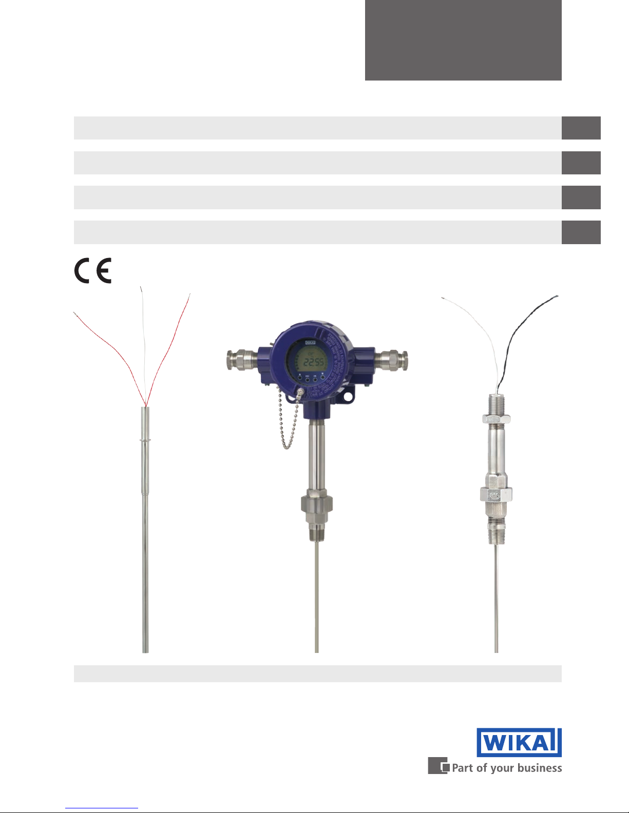
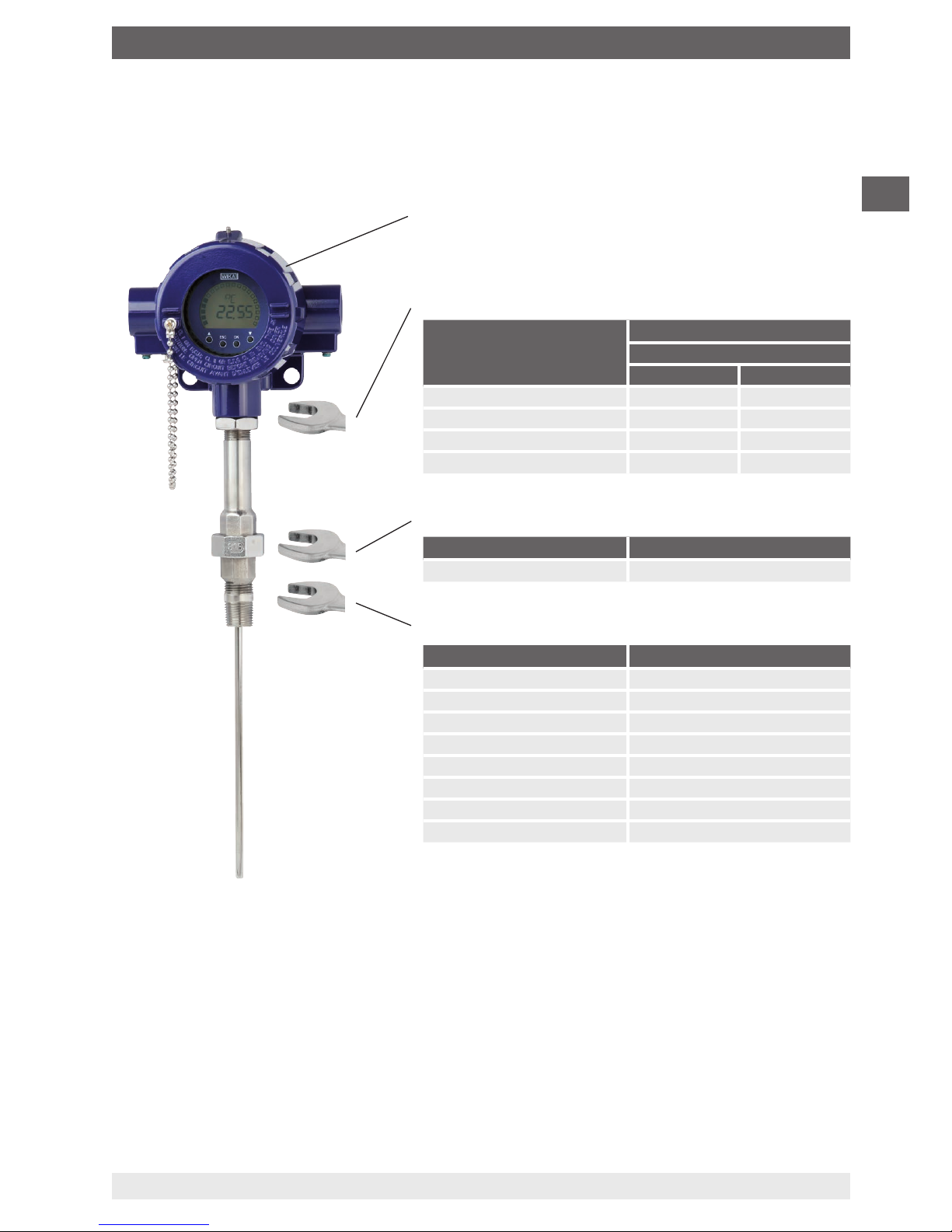
Models TR12-B, TC12-B Models TR12-M, TC12-MModels TR12-A, TC12-A
Resistance thermometer TR12 and thermocouple TC12
Widerstandsthermometer TR12 und Thermoelement TC12
Sonde à résistance TR12 et thermocouple TC12
Termorresistencia TR12 y termopar TC12
Page 2

EN
DE
FR
ES
2
14064370.02 08/2018 EN/DE/FR/ES
WIKA operating instructions models TR12, TC12
Operating instructions models TR12 and TC12
Page
3 - 28
Betriebsanleitung Typen TR12 und TC12
Seite
29 - 54
Mode d'emploi types TR12 et TC12
Page
55 - 80
Manual de instrucciones modelos TR12 y TC12
Página
81 - 105
© 08/2013 WIKA Alexander Wiegand SE & Co. KG
All rights reserved. / Alle Rechte vorbehalten.
WIKA
®
is a registered trademark in various countries.
WIKA
®
ist eine geschützte Marke in verschiedenen Ländern.
Prior to starting any work, read the operating instructions!
Keep for later use!
Vor Beginn aller Arbeiten Betriebsanleitung lesen!
Zum späteren Gebrauch aufbewahren!
Lire le mode d‘emploi avant de commencer toute opération !
A conserver pour une utilisation ultérieure !
¡Leer el manual de instrucciones antes de comenzar cualquier trabajo!
¡Guardar el manual para una eventual consulta!
Page 3
EN
14064370.02 08/2018 EN/DE/FR/ES
WIKA operating instructions models TR12, TC12
3
Contents
Contents
1. General information 4
2. Design and function 4
3. Safety 8
4. Transport, packaging and storage 11
5. Commissioning, operation 12
6. Faults 17
7. Maintenance, cleaning and calibration 19
8. Dismounting, return and disposal 20
9. Specifications 21
10. Accessories 27
Page 4

EN
14064370.02 08/2018 EN/DE/FR/ES
WIKA operating instructions models TR12, TC12
4
1. General information
■
The thermometers described in the operating instructions have been manufactured
using state-of-the-art technology.
■
These operating instructions contain important information on handling the instrument.
Working safely requires that all safety instructions and work instructions are observed.
■
Observe the relevant local accident prevention regulations and general safety
regulations for the instrument’s range of use.
■
Skilled personnel must have carefully read and understood the operating instructions
prior to beginning any work.
■
Subject to technical modifications.
■
Further information:
- Internet address: www.wika.de / www.wika.com
- Relevant data sheet: TE 60.16 (TR12-A)
TE 60.17 (TR12-B, TR12-M)
TE 65.16 (TC12-A)
TE 65.17 (TC12-B, TC12-M)
- Application consultant:
Tel.: +49 9372 132-0
Fax: +49 9372 132-406
info@wika.com
Abbreviations
RTD “Resistance temperature detector”; resistance thermometer
TC Thermocouple
2. Design and function
2.1 Description
The model TR12-B (resistance thermometer) and model TC12-B (thermocouple) electrical
thermometers consist of a module (TR12-M, TC12-M) which is built into a case. The
module is made up of a spring-loaded measuring insert (TR12-A, TC12-A) built into a neck
tube. The measuring insert (TR12-A, TC12-A) is replaceable.
The active measuring component of the measuring insert is manufactured from a welded
tube or from mineral-insulated cable, optionally in combination with ceramic-insulated
thermocouple wires. The sensor is embedded in ceramic powder, heat-resistant potting
compound, cement compound or thermally conductive paste.
1. General information / 2. Design and function
Page 5
EN
14064370.02 08/2018 EN/DE/FR/ES
WIKA operating instructions models TR12, TC12
5
If the temperature sensor is designed as a grounded thermocouple, the thermocouple
is joined directly to the sheath. Versions with a diameter smaller than 3 mm and with
grounded thermocouples should be considered as galvanically connected with earth
potential.
The connection side of the measuring insert consists of a transition sleeve with connected
bare wires.
This document describes standard versions of instruments. For applications in hazardous
areas special instrument designs are required.
For further information for operation in hazardous areas, see the additional information for
the corresponding ignition protection type (separate document).
CAUTION!
Damage to the instrument
To avoid damage to the instrument, thermometers of this model range must
be installed with a thermowell.
▶
Select a suitable thermowell (any type of thermowell can be selected) and
take the operational process data (temperature, pressure, density and
flow velocity) into account.
▶
The use of special designs without thermowell is possible, but is the
responsibility of the operator.
Possible sensor measuring ranges:
Model TR12: -200 ... +600 °C
Model TC12: -40 ... +1,200 °C
The following mounting and operating information has been compiled with care. However, it
is not possible to consider all potential usage cases.
2. Design and function
Page 6
EN
14064370.02 08/2018 EN/DE/FR/ES
WIKA operating instructions models TR12, TC12
6
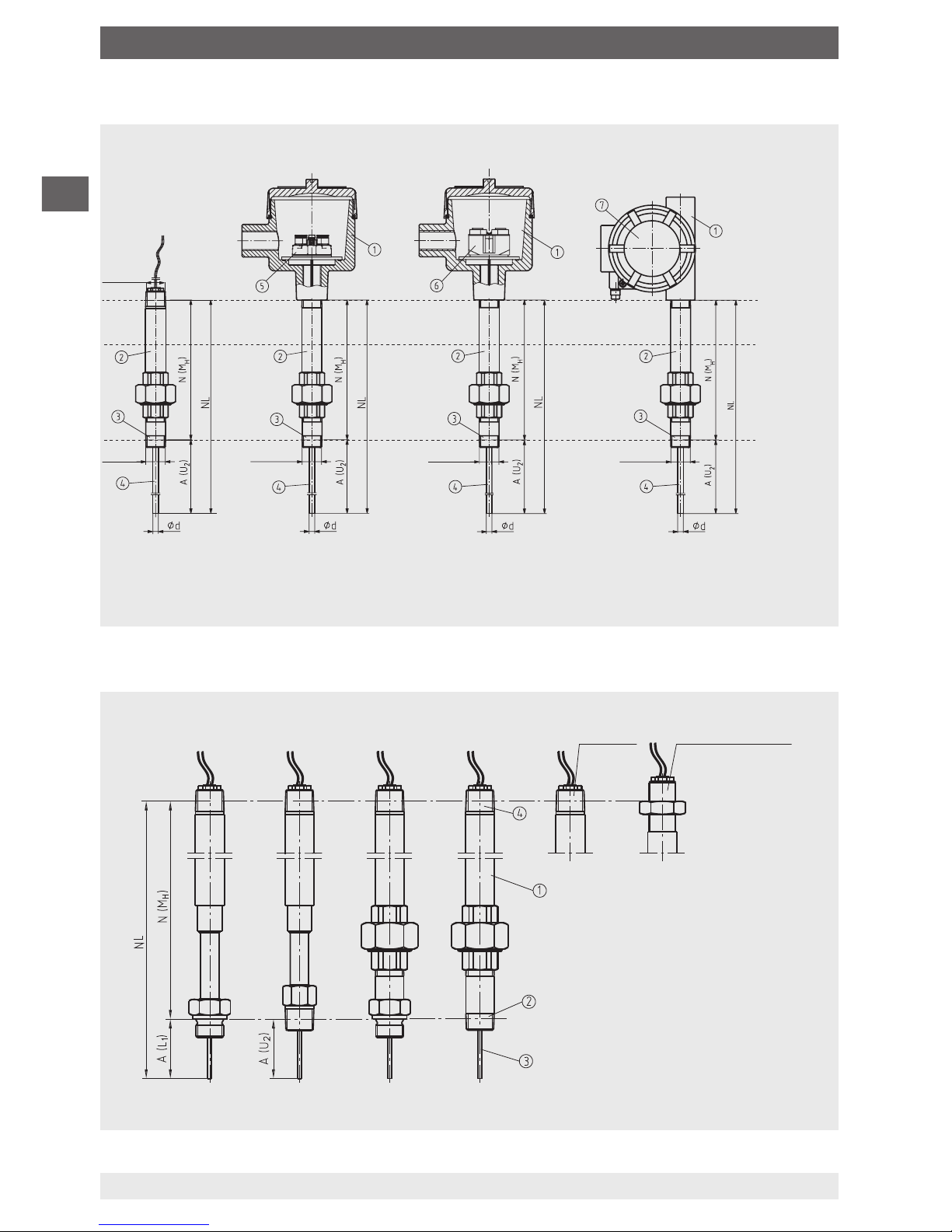
2.2 Technical description of the three variants
Legend:
Neck tube
Thread to the thermowell
Measuring insert
Thread to the connection head
A(U
2
) Insertion length
(tapered thread)
A(L
1
) Insertion length
(parallel thread)
NL Nominal length
N(M
H
) Neck length
tapered
thread
parallel
thread
14013854.02
parallel
thread
tapered
thread
fabricated neck tube
(neck tube welded)
“nipple-union-nipple”
neck tube
tapered thread
parallel thread with
counter nut
TR12-B, TC12-B
Variant 1
TR12-B, TC12-B
Variant 2
TR12-B, TC12-B
Variant 3
Thread
TR12-M, TC12-M
Module
Thread
Thread Thread Thread
Legend:
Connection head
Neck tube
Connection to thermowell
Measuring insert
Terminal block
Transmitter (option)
Field transmitter
14039769.01
T
max
= +80 °C
T
max
= +150 °C
T
max
= +300 °C
T
max
= undefined
2.3 Neck tube versions
2. Design and function
Page 7
EN
14064370.02 08/2018 EN/DE/FR/ES
WIKA operating instructions models TR12, TC12
7
2.4 Case- and connection heads
The dimensions of the case- and connection heads are given in the respective data sheet.
2.5 Tightening torques
Connection head, selectable (example)
Thread Tightening torques in Nm
Connection head material
Aluminium Stainless steel
1/2 NPT 32 35
3/4 NPT 36 40
M20 x 1.5, with counter nut
1)
23 25
M24 x 1.5, with counter nut
1)
27 30
Tightening torques between connection head and neck tube
Tightening torques for connection to thermowell
Tightening torques for connection to neck tube
1) only for versions with fabricated neck tube
Thread Tightening torques in Nm
R 1/2
1)
50 ... 60
Thread Tightening torques in Nm
1/2 NPT 35
3/4 NPT 40
G 1/2 B 35
G 3/4 B 40
M14 x 1.5 25 ... 30
M18 x 1.5 35
M20 x 1.5 35 ... 40
M27 x 2 40 ... 45
■
Only ever screw in, or unscrew, the instrument via the spanner flats and to the
prescribed torque using an appropriate tool.
■
The correct torque depends on the dimensions of the connection thread and the sealing
used (form/material).
■
When screwing in or unscrewing the instrument, do not use the connection head as
contact surface.
■
When screwing in the instrument, please observe that the threads are not skewed.
2.6 Scope of delivery
Cross-check scope of delivery with delivery note.
2. Design and function
Page 8

EN
14064370.02 08/2018 EN/DE/FR/ES
WIKA operating instructions models TR12, TC12
8
3. Safety
3.1 Explanation of symbols
WARNING!
... indicates a potentially dangerous situation that can result in serious injury
or death, if not avoided.
CAUTION!
... indicates a potentially dangerous situation that can result in light injuries or
damage to property or the environment, if not avoided.
WARNING!
... indicates a potentially dangerous situation that can result in burns, caused
by hot surfaces or liquids, if not avoided.
Information
... points out useful tips, recommendations and information for efficient and
trouble-free operation.
3.2 Intended use
These resistance thermometers and thermocouples are used for temperature
measurement in industrial applications. They can be combined with a variety of thermowell
designs, but the operational process data (temperature, pressure, density and flow
velocity) must be taken into account. Operation without thermowell is only recommended
in certain applications. The replaceable, centrically spring-loaded measuring insert and
its extended spring travel enable combination with the widest range of connection head
designs.
Neither repairs nor structural modifications are permitted, and any would void the
guarantee and the respective certification. The manufacturer shall not be responsible for
constructional modifications after delivery of the instruments.
The instrument has been designed and built solely for the intended use described here,
and may only be used accordingly.
The technical specifications contained in these operating instructions must be observed.
The manufacturer shall not be liable for claims of any type based on operation contrary to
the intended use.
3. Safety
Page 9
EN
14064370.02 08/2018 EN/DE/FR/ES
WIKA operating instructions models TR12, TC12
9
3.3 Responsibility of the operator
The system operator is responsible for selecting the thermometer or thermowell, and for
the selection of their materials, so as to guarantee their safe operation within the plant or
machine. When preparing a quote, WIKA can only give recommendations which are based
on our experience in similar applications.
The safety instructions within these operating instructions, as well as the safety, accident
prevention and environmental protection regulations for the application area must be
maintained.
The operator is obliged to maintain the product label in a legible condition.
3.4 Personnel qualification
WARNING!
Risk of injury should qualification be insufficient
Improper handling can result in considerable injury and damage to
equipment.
▶
The activities described in these operating instructions may only be
carried out by skilled electrical personnel who have the qualifications
described below.
Skilled electrical personnel
Skilled electrical personnel are understood to be personnel who, based on their technical
training, know-how and experience as well as their knowledge of country-specific
regulations, current standards and directives, are capable of carrying out work on
electrical systems and independently recognising and avoiding potential hazards. The
skilled electrical personnel have been specifically trained for the work environment they
are working in and know the relevant standards and regulations. The skilled electrical
personnel must comply with current legal accident prevention regulations.
Operating personnel
The personnel trained by the operator are understood to be personnel who, based on their
education, knowledge and experience, are capable of carrying out the work described and
independently recognising potential hazards.
Special operating conditions require further appropriate knowledge, e.g. of aggressive
media.
3. Safety
Page 10
EN
14064370.02 08/2018 EN/DE/FR/ES
WIKA operating instructions models TR12, TC12
10
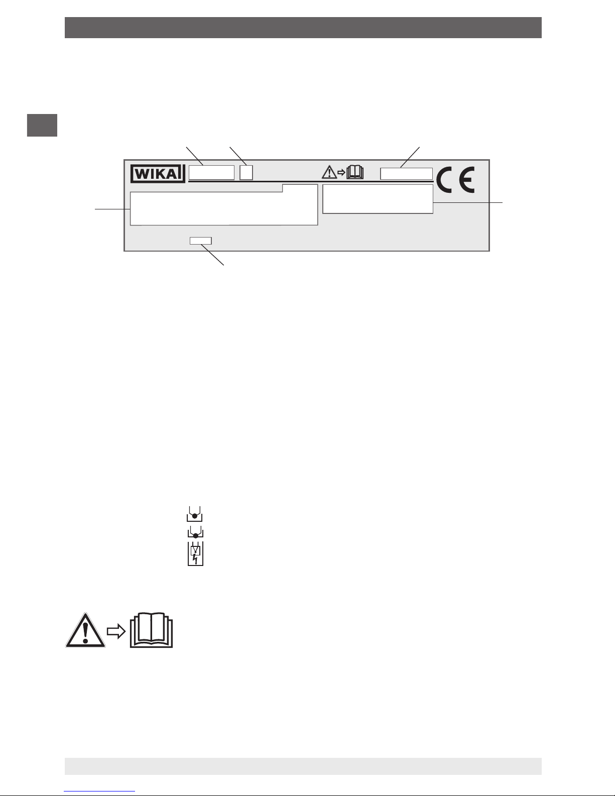
3.5 Labelling, safety marks
Product label (example)
Model
A = measuring insert
B = process thermometer
M = basic module
Serial number
Approval-related data
Year of manufacture
■
Information on version (measuring element, measuring range...)
Sensor in accordance with standard (resistance thermometer)
- F =
Thin-film measuring resistor
- W = Wire-wound measuring resistor
Sensor in accordance with standard (thermocouple)
- ungrounded = ungrounded welded
- grounded = welded to the sheath (grounded)
- quasi grounded = The thermometer is, due to its low insulation clearances between
resistance sensor and sheath, to be considered as grounded.
■
Transmitter model (only for design with transmitter)
Before mounting and commissioning the instrument, ensure you
read the operating instructions!
TR12-M-IDBZ
1 x Pt100 / A / 3 (F) -50 ... +500 °C
Um = DC 30 V / Pm = 2 W
BVS 07 ATEX E 071 X
IECEx BVS 11.0042X
II 2 G Ex db IIC T* Gb
EN 60751
0158
WIKA Alexander Wiegand SE & Co.KG, D-63911 Klingenberg
Made in Germany 2013
WARNING: DO NOT OPEN WHILE ENERGIZED!
11012345
3. Safety
Page 11
EN
14064370.02 08/2018 EN/DE/FR/ES
WIKA operating instructions models TR12, TC12
11
4. Transport, packaging and storage
4.1 Transport
Check the instrument for any damage that may have been caused by transport.
Obvious damage must be reported immediately.
CAUTION!
Damage through improper transport
With improper transport, a high level of damage to property can occur.
▶
When unloading packed goods upon delivery as well as during internal
transport, proceed carefully and observe the symbols on the packaging.
▶
With internal transport, observe the instructions in chapter 4.2 “Packaging
and storage”.
If the instrument is transported from a cold into a warm environment, the formation of
condensation may result in instrument malfunction. Before putting it back into operation,
wait for the instrument temperature and the room temperature to equalise.
4.2 Packaging and storage
Do not remove packaging until just before mounting.
Permissible conditions at the place of storage:
■
Storage temperature:
Instruments without built-in transmitter: -40 ... +80 °C
Instruments with built-in transmitter: see operating instructions of the transmitter in
question
■
Humidity: 35 ... 85 % relative humidity (non-condensing)
Avoid exposure to the following factors:
■
Direct sunlight or proximity to hot objects
■
Mechanical vibration, mechanical shock (putting it down hard)
■
Soot, vapour, dust and corrosive gases
■
Hazardous environments, flammable atmospheres
Store the instrument in its original packaging in a location that fulfils the conditions listed
above. If the original packaging is not available, pack and store the instrument as described
below:
1. Place the instrument, along with shock-absorbent material, in the packaging.
2. If stored for a prolonged period of time (more than 30 days), place a bag containing a
desiccant inside the packaging.
4. Transport, packaging and storage
Page 12
EN
14064370.02 08/2018 EN/DE/FR/ES
WIKA operating instructions models TR12, TC12
12
5. Commissioning, operation
WARNING!
Damage to the measuring instrument by operation outside the upper
or lower limits of the operating temperature
Failure to observe the permissible operating temperature, also taking
into account convection and radiation, can even cause damage to the
thermometer during mounting.
▶
The upper and lower limits of the specified operating temperature range
must not be exceeded.
During installation, take care to
■
Avoid distorting the cable sheath when tightening the pressure screw.
■
Avoid cutting too deep into the cable sheath.
■
Use suitable cable.
■
Be careful of the clamping area of the cable gland.
■
Thermometers must be earthed if dangerous voltages could be expected at the
connection wires (caused, for example, by mechanical damage, electrostatic charge or
induction)!
■
The protection class is not valid with armoured cables (stainless steel sheathed).
■
Seals should be checked for signs of brittleness and, if necessary, replaced.
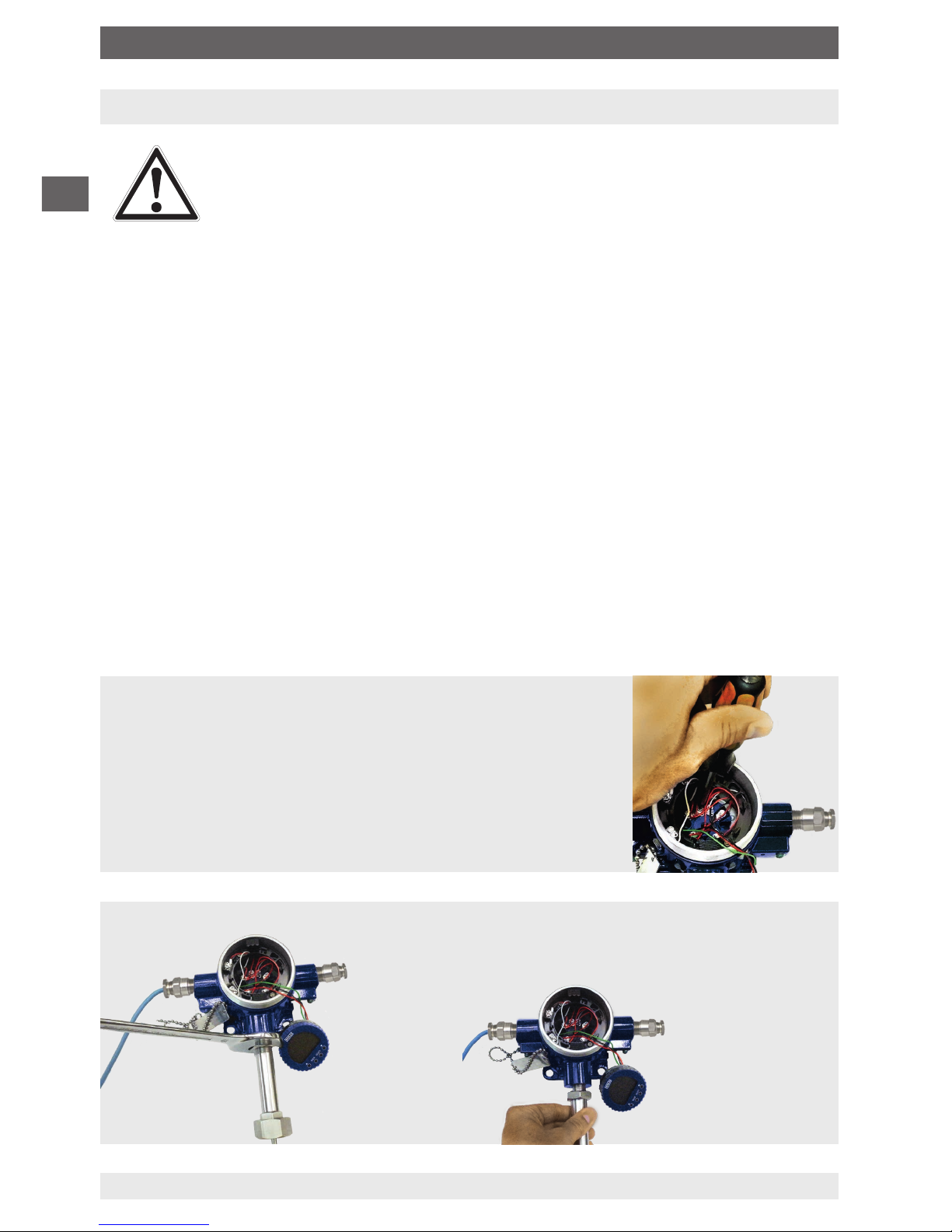
5.1 Removal and installation of the measuring insert
The bare wires have a cross-section of approx. 0.22 mm², are 150 mm long and are colourcoded dependent upon the sensor type. The measuring insert is secured against twisting.
Before removing the measuring insert, fully disconnect the
electrical connections to the terminal block or transmitter.
After that, the neck tube can be loosened and unscrewed from the head.
5. Commissioning, operation
Page 13
EN
14064370.02 08/2018 EN/DE/FR/ES
WIKA operating instructions models TR12, TC12
13
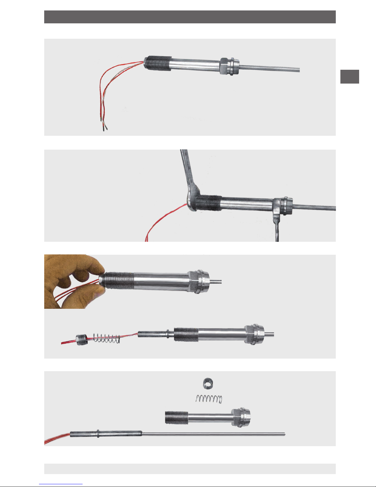
Removed measuring insert with neck tube:
To disconnect the measuring insert
from the neck tube, loosen the M16
bolt at the top end of the neck tube
and unscrew it.
5. Commissioning, operation
Page 14
EN
14064370.02 08/2018 EN/DE/FR/ES
WIKA operating instructions models TR12, TC12
14
The installation of the measuring insert is carried out in
the reverse order (clean the measuring insert prior to
installation).
The hexagonal crimped tip of the measuring insert is
guided by the screw-in of the hexagonal socket screw.
Tightening torque of the screw: 12 ... 14 Nm
5.2 Electrical mounting
Cable glands
Requirements for meeting ingress protection:
■
Only use cable glands within their indicated clamping area (cable diameter suitable for
the cable gland).
■
Do not use the lower clamping area with very soft cable types.
■
Only use round cables (if necessary, slightly oval in cross-section).
■
Do not twist the cable.
■
Repeated opening/closing is possible; however only if necessary, as it might have a
detrimental effect on the ingress protection
■
For cables with a pronounced cold-flow behaviour the screw connection must be fully
tightened.
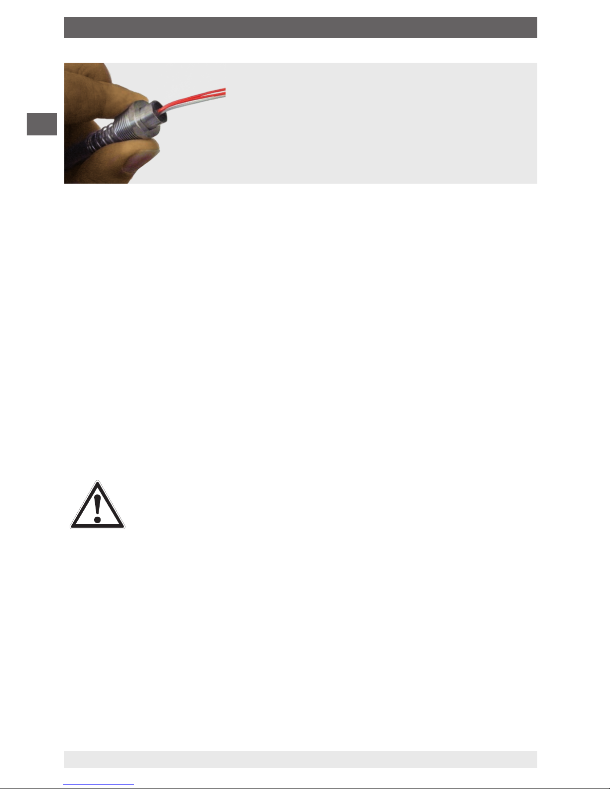
5.3 Electrical connection
CAUTION!
Danger of short circuit
Damage to cables, wires and connection points can lead to malfunction of
the instrument.
▶
Avoid damaging the cables and wires.
▶
Fine-stranded leads with bare ends must be finished with end splices
(cable preparation).
▶
Both the internal effective capacitance and inductance must be
considered.
The electrical connection is to be made according to the following sensor connections/
pin assignments.
5. Commissioning, operation
Page 15
EN
14064370.02 08/2018 EN/DE/FR/ES
WIKA operating instructions models TR12, TC12
15
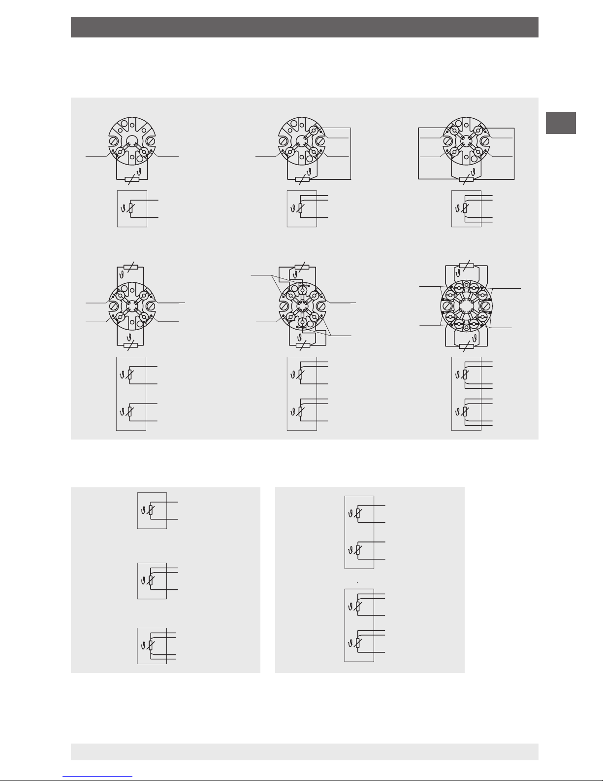
5.3.1 Resistance thermometer
■
With terminal block
■
With connection cable
3160629.06
red
1 x Pt100, 2-wire 1 x Pt100, 3-wire 1 x Pt100, 4-wire
white white
red
red
red
red
white
white
white
white
white
white
red
red
red
red
red
2 x Pt100, 2-wire
2 x Pt100, 3-wire
2 x Pt100, 4-wire
red
white
white
red
red
white
black
yellow
yellow
yellow
black
black
white
white
red
red
red
red
black
black
black
black
yellow
yellow
yellow
red
white
black
yellow
white
1 x Pt100
2-wire
1 x Pt100
3-wire
1 x Pt100
4-wire
2 x Pt100
2-wire
2 x Pt100
3-wire
red
red
red
red
red
red
red
red
white
white
white
white
white
white
black
black
black
yellow
yellow
3160629.06
5. Commissioning, operation
Page 16
EN
14064370.02 08/2018 EN/DE/FR/ES
WIKA operating instructions models TR12, TC12
16
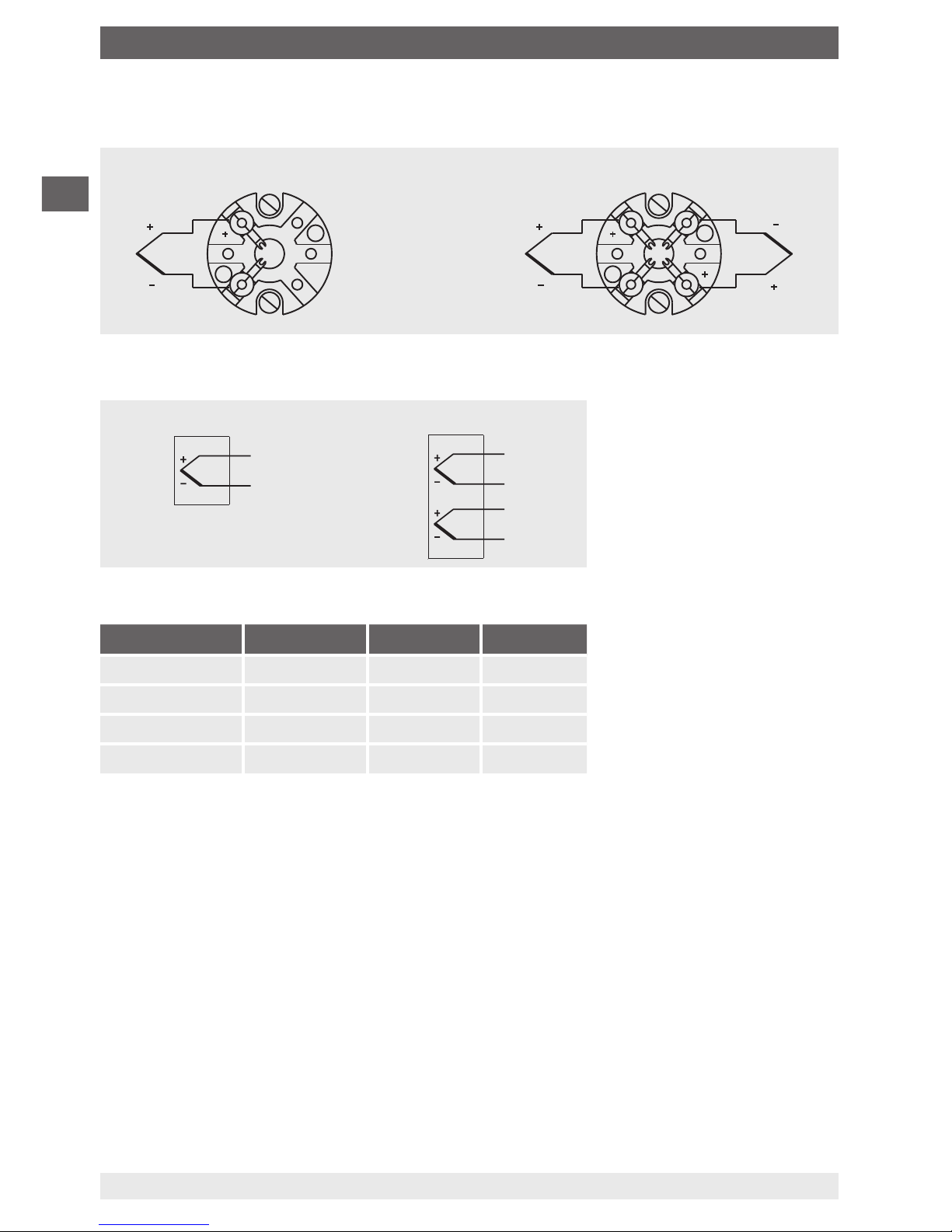
5.3.2 Thermocouples
■
With terminal block
■
With connection cable
Colour coding of cable strands
Sensor type Standard Positive Negative
K IEC 60584 Green White
J IEC 60584 Black White
E IEC 60584 Violet White
N IEC 60584 Pink White
Variant 1
For the electrical specifications (e.g. connection diagrams, tolerance values, etc.), see
chapter 6.1 “Electrical connection” or the data sheets TE 60.17 (for TR12) and TE 65.17
(for TC12).
Variant 2
For the electrical specifications (e.g. connection diagrams, tolerance values, etc.) please
refer to the relevant operating instructions and/or data sheet for the built-in head-mounted
transmitter.
Variant 3
For the electrical specifications (e.g. connection diagrams, tolerance values, etc.) please
refer to the relevant operating instructions and/or the relevant data sheet for the built-in field
transmitter.
Single thermocouple Dual thermocouple
The colour coding
at the positive poles
of the instrument
decides the
correlation of polarity
and terminal.
3166822.03
Single thermocouple Dual thermocouple
5. Commissioning, operation
Page 17
EN
14064370.02 08/2018 EN/DE/FR/ES
WIKA operating instructions models TR12, TC12
17
Variant 1 and 2
■
Junction between cable gland and connection head
M20 x 1.5 thread: Tightening torques 12 Nm
½ NPT thread: Tightening torques 30 Nm
■
Junction between cable and cable gland
Screw the pressure screw tightly into the adapter (use appropriate tools!)
6. Faults
CAUTION!
Physical injuries and damage to property and the environment
If faults cannot be eliminated by means of the listed measures, the instrument
must be taken out of operation immediately.
▶
Ensure that there is no longer any signal present and protect against being
put into operation accidentally.
▶
Contact the manufacturer.
▶
If a return is needed, please follow the instructions given in chapter 8.2
“Return”.
WARNING!
Physical injuries and damage to property and the environment caused
by hazardous media
Upon contact with hazardous media (e.g. oxygen, acetylene, flammable
or toxic substances), harmful media (e.g. corrosive, toxic, carcinogenic,
radioactive), and also with refrigeration plants and compressors, there is a
danger of physical injuries and damage to property and the environment.
Should a failure occur, aggressive media with extremely high temperature
and under high pressure or vacuum may be present at the instrument.
▶
For these media, in addition to all standard regulations, the appropriate
existing codes or regulations must also be followed.
▶
Wear the required protective equipment (depending on the application; the
thermometer itself is basically not dangerous).
For contact details see chapter 1 “General information” or the back page of
the operating instructions.
5. Commissioning, operation / 6. Faults
Page 18

EN
14064370.02 08/2018 EN/DE/FR/ES
WIKA operating instructions models TR12, TC12
18
Faults Causes Measures
No signal/cable break Mechanical load too high or
overtemperature
Replace probe or measuring insert
with one of a suitable design
Erroneous measured
values
Sensor drift caused by
overtemperature
Replace probe or measuring insert
with one of a suitable design
Sensor drift caused by
chemical attack
Use a suitable thermowell.
Erroneous measured
values (too low)
Entry of moisture into cable
or measuring insert
Replace probe or measuring insert
with one of a suitable design
Erroneous measured
values and response
times too long
Wrong mounting geometry,
for example mounting depth
too deep or heat dissipation
too high
The temperature-sensitive area
of the sensor must be inside the
medium, and surface measurements
must be ungrounded
Deposits on the sensor or
thermowell
Remove deposits
Erroneous measured
values (of thermocouples)
Parasitic voltages (thermal
voltages, galvanic voltage) or
wrong equalisation line
Use suitable compensating cable
Temporary or sporadic
interruptions of the
measured value signal
Cable break in connection
cable or loose contact
caused by mechanical
overload
Replace probe or measuring insert
with a suitable design, for example
equipped with a bend protection
spring or a thicker conductor crosssection
Corrosion Composition of the medium
not as expected or modified
or wrong thermowell material
selected
Analyse medium and then select a
more suitable material or replace
thermowell regularly
Signal interference Stray currents caused by
electric fields or earth circuits
Use shielded connection leads, and
increase the distance to motors and
power cables
Earth circuits Eliminate potential differences by
using galvanically isolated barriers
or transmitters
6. Faults
Page 19
EN
14064370.02 08/2018 EN/DE/FR/ES
WIKA operating instructions models TR12, TC12
19
7. Maintenance, cleaning and calibration
For contact details see chapter 1 “General information” or the back page of
the operating instructions.
7.1 Maintenance
The thermometers described here are maintenance-free.
Repairs must only be carried out by the manufacturer.
7.2 Cleaning
CAUTION!
Physical injuries and damage to property and the environment
Improper cleaning may lead to physical injuries and damage to property and
the environment. Residual media in the dismounted instrument can result in a
risk to persons, the environment and equipment.
▶
Carry out the cleaning process as described below.
1. Prior to cleaning, disconnect the electrical connections properly.
2. Use the required protective equipment (depending on the application; the thermometer
itself is basically not dangerous).
3. Clean the instrument with a moist cloth.
This applies in particular to thermometers with a case made of plastic to ensure that any
risk of electrostatic charge is avoided.
Electrical connections must not come into contact with moisture!
CAUTION!
Damage to the instrument
Improper cleaning may lead to damage to the instrument!
▶
Do not use any aggressive cleaning agents.
▶
Do not use any hard or pointed objects for cleaning.
4. Wash or clean the dismounted instrument, in order to protect persons and the
environment from exposure to residual media.
7.3 Calibration, recalibration
It is recommended that the measuring insert is recalibrated at regular intervals (resistance
thermometers: approx. 24 months, thermocouples: approx. 12 months). This period can
reduce, depending on the particular application. The calibration can be carried out by the
manufacturer, as well as on site by qualified skilled personnel with calibration instruments.
7. Maintenance, cleaning and calibration
Page 20
EN
14064370.02 08/2018 EN/DE/FR/ES
WIKA operating instructions models TR12, TC12
20
8. Dismounting, return and disposal
8.1 Dismounting
WARNING!
Physical injuries and damage to property and the environment
through residual media
Upon contact with hazardous media (e.g. oxygen, acetylene, flammable
or toxic substances), harmful media (e.g. corrosive, toxic, carcinogenic,
radioactive), and also with refrigeration plants and compressors, there is a
danger of physical injuries and damage to property and the environment.
▶
Before storage of the dismounted instrument (following use) wash or
clean it, in order to protect persons and the environment from exposure to
residual media.
▶
Use the required protective equipment (depending on the application; the
thermometer itself is basically not dangerous).
▶
Observe the information in the material safety data sheet for the
corresponding medium.
Only disconnect the thermometer once the system has been depressurised.
WARNING!
Risk of burns
During dismounting there is a risk of dangerously hot media escaping.
▶
Let the instrument cool down sufficiently before dismounting it!
8.2 Return
Strictly observe the following when shipping the instrument:
All instruments delivered to WIKA must be free from any kind of hazardous substances
(acids, bases, solutions, etc.) and must therefore be cleaned before being returned.
WARNING!
Physical injuries and damage to property and the environment
through residual media
Residual media in the dismounted instrument can result in a risk to persons,
the environment and equipment.
▶
With hazardous substances, include the material safety data sheet for the
corresponding medium.
▶
Clean the instrument, see chapter 7.2 “Cleaning”.
When returning the instrument, use the original packaging or a suitable transport packaging.
To avoid damage:
1. Place the instrument, along with shock-absorbent material, in the packaging.
Place shock-absorbent material evenly on all sides of the transport packaging.
2. If possible, place a bag containing a desiccant inside the packaging.
3. Label the shipment as carriage of a highly sensitive measuring instrument.
8. Dismounting, return and disposal
Page 21
EN
14064370.02 08/2018 EN/DE/FR/ES
WIKA operating instructions models TR12, TC12
21
Information on returns can be found under the heading “Service” on our local
website.
8.3 Disposal
Incorrect disposal can put the environment at risk.
Dispose of instrument components and packaging materials in an environmentally
compatible way and in accordance with the country-specific waste disposal regulations.
Do not dispose of with household waste. Ensure a proper disposal in
accordance with national regulations.
9. Specifications
9.1 Models TR12-A, TR12-M
Output signal Pt100
Temperature range Measuring range -200 ... +600 °C
Measuring element
(measuring current: 0.1 ... 1.0 mA)
1)
Pt100 measuring resistor
Connection method 1 x 2-wire, 1 x 3-wire, 1 x 4-wire, 2 x 2-wire, 2 x 3-wire,
2 x 4-wire
2)
Tolerance value of the measuring
element per EN 60751 Class B
Class A
Class AA
Wire-wound Thin film
-200 ... +600 °C
-100 ... +450 °C
-50 ... +250 °C
-50 ... +500 °C
-30 ... +300 °C
0 ... 150 °C
Measuring insert (replaceable)
Material Stainless steel 1.4571, 316/316L
Diameter Standard: 3 mm
3)
, 6 mm, 8 mm (with sleeve)
Option (on request): 1/8" 3) (3.17 mm), 1/4" (6.35 mm), 3/8" (9.53 mm)
Spring travel approx. 20 mm
Response time (in
water, per EN 60751)
t
50
< 10 s t90 < 20 s (measuring insert diameter 6 mm: The thermowell
required for operation increases the response time dependent upon the
actual parameters for the thermowell and the process.)
Use resistance thermometers with shielded cable, and, if the lines are longer than 30 m or leave the building, ground the
shield on at least one end of the lead. For a correct determination of the overall measuring deviation, both sensor and
transmitter measuring deviations have to be considered.
1) For detailed specifications for Pt100 sensors, see Technical information IN 00.17 at www.wika.com.
2) Not for 3 mm diameter
3) Not for 2 x 4-wire connection method
8. Dismounting, return and disposal / 9. Specifications
Page 22

EN
14064370.02 08/2018 EN/DE/FR/ES
WIKA operating instructions models TR12, TC12
22
Neck tube (only model TR12-M)
Material Stainless steel 1.4571, 316/316L
Connection thread to the
thermowell
G 1/2 B, G 3/4 B, 1/2 NPT, 3/4 NPT, M14 x 1.5, M18 x 1.5,
M20 x 1.5, M27 x 2
Connection thread to the head
■
M20 x 1.5 with counter nut
■
M24 x 1.5 with counter nut
■
1/2 NPT
■
3/4 NPT
Neck length
■
min. 150 mm, standard neck length
■
200 mm
■
250 mm
other neck lengths on request
Ambient conditions
Ambient and storage
temperature
-60
4)
/ -40 ... +80 °C
Ingress protection IP00 per IEC/EN 60529
Vibration resistance
■
6 g peak-to-peak, wire-wound measuring resistor or thin film (standard)
■
20 g peak-to-peak, thin-film measuring resistor (option)
■
50 g peak-to-peak, thin-film measuring resistor (option)
5)
4) Special version on request (only available with selected approvals), other ambient and storage temperature on request
For further specifications see WIKA data sheets TE 60.16, TE 60.17 and the order
documentation.
9.2 Model TR12-B
Output signal Pt100
Temperature range Measuring range -200 ... +600 °C
Measuring element
(measuring current: 0.1 ... 1.0 mA)
6)
Pt100 measuring resistor
Connection method 1 x 2-wire, 1 x 3-wire, 1 x 4-wire, 2 x 2-wire, 2 x 3-wire,
2 x 4-wire
Tolerance value of the measuring
element per EN 60751 Class B
Class A
Class AA
Wire-wound Thin film
-200 ... +600 °C
-100 ... +450 °C
-50 ... +250 °C
-50 ... +500 °C
-30 ... +300 °C
0 ... 150 °C
Use resistance thermometers with shielded cable, and, if the lines are longer than 30 m or leave the building, ground
the shield on at least one end of the lead. For a correct determination of the overall measuring deviation, both sensor
and transmitter measuring deviations have to be considered.
5) For measuring insert diameter < 8 mm
6) For detailed specifications for Pt100 sensors, see Technical information IN 00.17 at www.wika.com.
9. Specifications
Page 23

EN
14064370.02 08/2018 EN/DE/FR/ES
WIKA operating instructions models TR12, TC12
23
Output signal 4 ... 20 mA, HART® protocol, FOUNDATION™ Fieldbus and
PROFIBUS
®
PA
7)
Transmitter model (selectable versions) T15 T32 T53 TIF50, TIF52
Data sheet TE 15.01 TE 32.04 TE 53.01 TE 62.01
Output
■
4 ... 20 mA x x x
■
HART® protocol x x
■
FOUNDATION™ Fieldbus and
PROFIBUS® PA
x
Connection method
1 x 2-wire, 3-wire or 4-wire x x x x
Measuring current < 0.2 mA < 0.3 mA < 0.2 mA < 0.3 mA
Measuring insert (replaceable)
Material Stainless steel 1.4571, 316/316L
Diameter Standard: 3 mm
8)
, 6 mm, 8 mm (with sleeve)
Option (on request): 1/8" 8) (3.17 mm), 1/4" (6.35 mm), 3/8" (9.53 mm)
Spring travel approx. 20 mm
Response time (in
water, per EN 60751)
t
50
< 10 s t90 < 20 s (measuring insert diameter 6 mm: The thermowell
required for operation increases the response time dependent upon the
actual parameters for the thermowell and the process.)
Neck tube
Material Stainless steel 1.4571, 316/316L
Connection thread to
the thermowell
G 1/2 B, G 3/4 B, 1/2 NPT, 3/4 NPT, M14 x 1.5, M18 x 1.5, M20 x 1.5,
M27 x 2
Connection thread to
the head
■
M20 x 1.5 with counter nut
■
M24 x 1.5 with counter nut
■
1/2 NPT
■
3/4 NPT
Neck length
■
min. 150 mm, standard neck length
■
200 mm
■
250 mm
other neck lengths on request
7) Protect the temperature transmitter from temperatures > 85 °C.
8) Not for 2 x 4-wire connection method
9. Specifications
Page 24

EN
14064370.02 08/2018 EN/DE/FR/ES
WIKA operating instructions models TR12, TC12
24
Ambient conditions
Ambient and storage
temperature
-60
9)
/ -40 ... +80 °C
Ingress protection IP66 per IEC/EN 60529
The specified ingress protection only applies with corresponding thermowell,
connection head, cable gland and appropriate cable dimensions
Vibration resistance
■
6 g peak-to-peak, wire-wound measuring resistor or thin film (standard)
■
20 g peak-to-peak, thin-film measuring resistor (option)
■
50 g peak-to-peak, thin-film measuring resistor (option)
10)
9) Special version on request (only available with selected approvals), other ambient and storage temperature on request
10) For measuring insert diameter < 8 mm
For further specifications see WIKA data sheet TE 60.17 and the order documentation.
9.3 Models TC12-A, TC12-M
Output signal thermocouple
Recommended max. operating temperature
■
Type K
■
Type J
■
Type E
■
Type N
1,200 °C
800 °C
800 °C
1,200 °C
Thermocouple per DIN EN 60584-1
11)
Types K, J, E, N
Measuring point
■
Ungrounded welded (ungrounded)
■
Grounded
Tolerance value of the measuring element
■
per EN 60584-1
■
per ASTM E230 (only for types K and J)
Class 1 and 2
Standard and special
Measuring insert (replaceable)
Material Inconel 600, others on request
Diameter Standard: 3 mm, 4.5 mm, 6 mm, 8 mm
Option (on request): 1/8" (3.17 mm), 1/4" (6.35 mm), 3/8" (9.53 mm)
Spring travel approx. 20 mm
Response time (in
water, per EN 60751)
t
50
< 5 s t90 < 10 s (measuring insert diameter 6 mm: The thermowell
required for operation increases the response time dependent upon the
actual parameters for the thermowell and the process.)
11) For detailed specifications for thermocouples, see Technical information IN 00.23 at www.wika.com.
9. Specifications
Page 25

EN
14064370.02 08/2018 EN/DE/FR/ES
WIKA operating instructions models TR12, TC12
25
Neck tube (only model TC12-M)
Material Stainless steel 1.4571, 316/316L
Connection thread to
the thermowell
G 1/2 B, G 3/4 B, 1/2 NPT, 3/4 NPT, M14 x 1.5, M18 x 1.5, M20 x 1.5,
M27 x 2
Connection thread to
the head
■
M20 x 1.5 with counter nut
■
M24 x 1.5 with counter nut
■
1/2 NPT
■
3/4 NPT
Neck length
■
min. 150 mm, standard neck length
■
200 mm
■
250 mm
other neck lengths on request
Ambient conditions
Ambient and storage temperature -60
12)
/ -40 ... +80 °C
Ingress protection IP00 per IEC/EN 60529
Vibration resistance 50 g, peak-to-peak
12) Special version on request (only available with selected approvals), other ambient and storage temperature on request
For further specifications see WIKA data sheets TE 65.16, TE 65.17 and the order
documentation.
9.4 Model TC12-B
Output signal thermocouple
Recommended max. operating temperature
■
Type K
■
Type J
■
Type E
■
Type N
1,200 °C
800 °C
800 °C
1,200 °C
Thermocouple per DIN EN 60584-1
13)
Types K, J, E, N
Measuring point
■
Ungrounded welded (ungrounded)
■
Grounded
Tolerance value of the measuring element
■
per EN 60584-1
■
per ASTM E230 (only for types K and J)
Class 1 and 2
Standard and special
13) For detailed specifications for thermocouples, see Technical information IN 00.23 at www.wika.com.
9. Specifications
Page 26

EN
14064370.02 08/2018 EN/DE/FR/ES
WIKA operating instructions models TR12, TC12
26
Output signal 4 ... 20 mA, HART® protocol, FOUNDATION™ Fieldbus and
PROFIBUS
®
PA
14)
Transmitter model (selectable versions) T16 T32 T53 TIF50, TIF52
Data sheet TE 16.01 TE 32.04 TE 53.01 TE 62.01
Output
■
4 ... 20 mA x x x
■
HART® protocol x x
■
FOUNDATION™ Fieldbus and
PROFIBUS® PA
x
Galvanic isolation x x x x
Measuring insert (replaceable)
Material Ni alloy 2.4816 (Inconel 600), others on request
Diameter Standard: 3 mm, 4.5 mm, 6 mm, 8 mm
Option (on request): 1/8" (3.17 mm), 1/4" (6.35 mm), 3/8" (9.53 mm)
Spring travel approx. 20 mm
Response time (in
water, per EN 60751)
t
50
< 5 s t90 < 10 s (measuring insert diameter 6 mm: The thermowell
required for operation increases the response time dependent upon
the actual parameters for the thermowell and the process.)
Neck tube
Material Stainless steel 1.4571, 316/316L
Connection thread to
the thermowell
G 1/2 B, G 3/4 B, 1/2 NPT, 3/4 NPT, M14 x 1.5, M18 x 1.5, M20 x 1.5,
M27 x 2
Connection thread to
the head
■
M20 x 1.5 with counter nut
■
M24 x 1.5 with counter nut
■
1/2 NPT
■
3/4 NPT
Neck length
■
min. 150 mm, standard neck length
■
200 mm
■
250 mm
other neck lengths on request
14) Protect the temperature transmitter from temperatures > 85 °C.
9. Specifications
Page 27
EN
14064370.02 08/2018 EN/DE/FR/ES
WIKA operating instructions models TR12, TC12
27
Ambient conditions
Ambient and storage
temperature
-60
15)
/ -40 ... +80 °C
Ingress protection IP66 per IEC/EN 60529
The specified ingress protection only applies with corresponding
thermowell, connection head, cable gland and appropriate cable
dimensions
Vibration resistance 50 g, peak-to-peak
15) Special version on request (only available with selected approvals), other ambient and storage temperature on request
For further specifications see WIKA data sheet TE 65.17 and the order documentation.
10. Accessories
The seals can be ordered from WIKA, indicating the WIKA order number and/
or the designation (see table).
WIKA order
number
Designation Suitable for
threads
11349981 per DIN 7603 form C 14 x 18 x 2 -CuFA G ¼, M14 x 1.5
11349990 per DIN 7603 form C 18 x 22 x 2 -CuFA G ⅜, M18 x 1.5
11350008 per DIN 7603 form C 21 x 26 x 2 -CuFA G ½, M20 x 1.5
11350016 per DIN 7603 form C 27 x 32 x 2.5 -CuFA G ¾, M27 x 2
Legend:
CuFA = Copper, max. 45HB
a
; filled with asbestos-free sealing material
9. Specifications / 10. Accessories
Page 28

EN
14064370.02 08/2018 EN/DE/FR/ES
WIKA operating instructions models TR12, TC12
28
Page 29

DE
WIKA Betriebsanleitung Typen TR12, TC12
29
14064370.02 08/2018 EN/DE/FR/ES
Inhalt
Inhalt
1. Allgemeines 30
2. Aufbau und Funktion 30
3. Sicherheit 34
4. Transport, Verpackung und Lagerung 37
5. Inbetriebnahme, Betrieb 38
6. Störungen 43
7. Wartung, Reinigung und Kalibrierung 45
8. Demontage, Rücksendung und Entsorgung 46
9. Technische Daten 47
10. Zubehör 53
Page 30

DE
WIKA Betriebsanleitung Typen TR12, TC12
30
14064370.02 08/2018 EN/DE/FR/ES
1. Allgemeines
■
Die in der Betriebsanleitung beschriebenen Thermometer werden nach dem aktuellen
Stand der Technik gefertigt.
■
Diese Betriebsanleitung gibt wichtige Hinweise zum Umgang mit dem Gerät. Voraussetzung für sicheres Arbeiten ist die Einhaltung aller angegebenen Sicherheitshinweise
und Handlungsanweisungen.
■
Die für den Einsatzbereich des Gerätes geltenden örtlichen Unfallverhütungsvorschriften und allgemeinen Sicherheitsbestimmungen einhalten.
■
Das Fachpersonal muss die Betriebsanleitung vor Beginn aller Arbeiten sorgfältig
durchgelesen und verstanden haben.
■
Technische Änderungen vorbehalten.
■
Weitere Informationen:
- Internet-Adresse: www.wika.de / www.wika.com
- zugehöriges Datenblatt: TE 60.16 (TR12-A)
TE 60.17 (TR12-B, TR12-M)
TE 65.16 (TC12-A)
TE 65.17 (TC12-B, TC12-M)
- Anwendungsberater:
Tel.: +49 9372 132-0
Fax: +49 9372 132-406
info@wika.de
Abkürzungen
RTD englisch: „Resistance temperature detector“; Widerstandsthermometer
TC englisch: „Thermocouple“; Thermoelement
2. Aufbau und Funktion
2.1 Beschreibung
Die elektrischen Thermometer Typ TR12-B (Widerstandsthermometer) bzw. Typ TC12-B
(Thermoelement) bestehen aus einem Modul (TR12-M, TC12-M) welches an ein Gehäuse
angebaut ist. Das Modul besteht aus einem federnd gelagertem Messeinsatz (TR12-A,
TC12-A) eingebaut in ein Halsrohr. Der Messeinsatz (TR12-A, TC12-A) ist auswechselbar.
Der messaktive Teil des Messeinsatzes ist hergestellt aus einem angeschweißten
Röhrchen oder aus mineralisolierter Leitung, optional in Kombination mit keramikisolierten
Thermodrähten. Der Sensor ist eingebettet in Keramikpulver, hitzebeständiger Vergussmasse, Zementkitt oder Wärmeleitpaste.
1. Allgemeines / 2. Aufbau und Funktion
Page 31

DE
WIKA Betriebsanleitung Typen TR12, TC12
31
14064370.02 08/2018 EN/DE/FR/ES
Wenn der Temperatursensor als geerdetes Thermoelement ausgeführt ist, ist das Thermopaar direkt mit dem Mantel verbunden. Ausführungen mit Durchmesser kleiner 3 mm und
geerdete Thermoelemente sind als galvanisch mit Erdpotential verbunden zu betrachten.
Die Anschlussseite des Messeinsatzes besteht aus einer Übergangshülse mit verbundenen Anschlusslitzen.
Dieses Dokument beschreibt Geräte in Standardausführung. Für Anwendungen in explosionsgefährdeten Bereichen sind spezielle Geräteausführungen erforderlich.
Weitere Informationen für den Einsatz im explosionsgefährdeten Bereich siehe Zusatzinformation für die entsprechende Zündschutzart (separates Dokument).
VORSICHT!
Beschädigung des Gerätes
Um Beschädigungen am Gerät zu vermeiden müssen Thermometer dieser
Typenreihen mit einem Schutzrohr verbaut werden.
▶
Geeignetes Schutzrohr auswählen (Schutzrohrbauform beliebig wählbar)
und die operativen Prozessdaten (Temperatur, Druck, Dichte und
Strömungsgeschwindigkeit) berücksichtigen.
▶
Der Einsatz von Sonderbauformen ohne Schutzrohr ist möglich, unterliegt
aber der Verantwortung des Betreibers.
Mögliche Sensormessbereiche:
Typ TR12: -200 ... +600 °C
Typ TC12: -40 ... +1.200 °C
Die nachfolgenden Einbau- und Betriebshinweise haben wir mit Sorgfalt zusammengestellt. Es ist jedoch nicht möglich, alle erdenklichen Anwendungsfälle zu berücksichtigen.
2. Aufbau und Funktion
Page 32

DE
WIKA Betriebsanleitung Typen TR12, TC12
32
14064370.02 08/2018 EN/DE/FR/ES
2.2 Technische Beschreibung der drei Varianten
Legende:
Halsrohr
Gewinde zum Schutzrohr
Messeinsatz
Gewinde zum Anschlusskopf
A(U
2
) Einbaulänge
(kegeliges Gewinde)
A(L
1
) Einbaulänge
(zylindrisches Gewinde)
NL Nennlänge
N(M
H
) Halslänge
kegeliges
Gewinde
zylindrisches
Gewinde
14013854.02
zylindrisches
Gewinde
kegeliges
Gewinde
nicht-teilbares Halsrohr
(Halsrohr verschweißt)
teilbares Halsrohr
(Nipple-Union-Nipple)
kegeliges
Gewinde
zylindrisches Gewinde
mit Kontermutter
TR12-B, TC12-B
Variante 1
TR12-B, TC12-B
Variante 2
TR12-B, TC12-B
Variante 3
Gewinde
TR12-M, TC12-M
Modul
Gewinde
Gewinde Gewinde Gewinde
Legende:
Anschlusskopf
Halsrohr
Anschluss zum Schutzrohr
Messeinsatz
Klemmsockel
Transmitter (Option)
Feldtransmitter
14039769.01
T
max
= +80 °C
T
max
= +150 °C
T
max
= +300 °C
T
max
= undefiniert
2.3 Halsrohrausführungen
2. Aufbau und Funktion
Page 33

DE
WIKA Betriebsanleitung Typen TR12, TC12
33
14064370.02 08/2018 EN/DE/FR/ES
2.4 Gehäuse- und Anschlussköpfe
Die Abmessungen der Gehäuse- bzw. Anschlussköpfe dem jeweiligen Datenblatt entnehmen.
2.5 Anzugsdrehmomente
Anschlusskopf, wählbar (Beispiel)
Gewinde Anzugsdrehmomente in Nm
Werkstoff Anschlusskopf
Aluminium CrNi-Stahl
1/2 NPT 32 35
3/4 NPT 36 40
M20 x 1,5 mit Kontermutter
1)
23 25
M24 x 1,5 mit Kontermutter
1)
27 30
Anzugsdrehmomente zwischen Anschlusskopf und Halsrohr
Anzugsdrehmomente für Anschluss zum Schutzrohr
Anzugsdrehmomente für Anschluss zum Halsrohr
1) nur bei Ausführungen mit nicht teilbarem Halsrohr
Gewinde Anzugsdrehmomente in Nm
R 1/2
1)
50 ... 60
Gewinde Anzugsdrehmomente in Nm
1/2 NPT 35
3/4 NPT 40
G 1/2 B 35
G 3/4 B 40
M14 x 1,5 25 ... 30
M18 x 1,5 35
M20 x 1,5 35 ... 40
M27 x 2 40 ... 45
■
Das Gerät nur über die Schlüsselflächen mit einem geeigneten Werkzeug und dem
vorgeschriebenen Drehmoment ein- bzw. ausschrauben.
■
Das richtige Drehmoment ist abhängig von der Dimension des Anschlussgewindes
sowie der verwendeten Dichtung (Form/Werkstoff).
■
Zum Ein- bzw. Ausschrauben nicht den Anschlusskopf als Angriffsfläche verwenden.
■
Beim Einschrauben beachten, dass die Gewindegänge nicht verkantet werden.
2.6 Lieferumfang
Lieferumfang mit dem Lieferschein abgleichen.
2. Aufbau und Funktion
Page 34

DE
WIKA Betriebsanleitung Typen TR12, TC12
34
14064370.02 08/2018 EN/DE/FR/ES
3. Sicherheit
3.1 Symbolerklärung
WARNUNG!
... weist auf eine möglicherweise gefährliche Situation hin, die zum Tod oder
zu schweren Verletzungen führen kann, wenn sie nicht gemieden wird.
VORSICHT!
... weist auf eine möglicherweise gefährliche Situation hin, die zu geringfügigen oder leichten Verletzungen bzw. Sach- und Umweltschäden führen kann,
wenn sie nicht gemieden wird.
WARNUNG!
... weist auf eine möglicherweise gefährliche Situation hin, die durch heiße
Oberflächen oder Flüssigkeiten zu Verbrennungen führen kann, wenn sie
nicht gemieden wird.
Information
... hebt nützliche Tipps und Empfehlungen sowie Informationen für einen
effizienten und störungsfreien Betrieb hervor.
3.2 Bestimmungsgemäße Verwendung
Diese Widerstandsthermometer und Thermoelemente dienen zur Temperaturmessung
in industriellen Anwendungen. Sie können mit einer Vielzahl von Schutzrohrbauformen
kombiniert werden, jedoch müssen die operativen Prozessdaten (Temperatur, Druck,
Dichte und Strömungsgeschwindigkeit) berücksichtigt werden. Ein Betrieb ohne Schutzrohr ist nur in speziellen Fällen zweckmäßig. Der auswechselbare, zentrisch gefederte Messeinsatz und sein erweiterter Federweg ermöglichen die Kombination mit den
verschiedensten Anschlusskopfvarianten.
Reparaturen sowie bauliche Veränderungen sind nicht zulässig und führen zur Erlöschung
der Garantie und der jeweiligen Zulassung. Bauliche Veränderungen nach Auslieferung der
Geräte obliegen nicht in der Verantwortung des Herstellers.
Das Gerät ist ausschließlich für den hier beschriebenen bestimmungsgemäßen Verwendungszweck konzipiert und konstruiert und darf nur dementsprechend verwendet werden.
Die technischen Spezifikationen in dieser Betriebsanleitung sind einzuhalten.
Ansprüche jeglicher Art aufgrund von nicht bestimmungsgemäßer Verwendung sind
ausgeschlossen.
3. Sicherheit
Page 35

DE
WIKA Betriebsanleitung Typen TR12, TC12
35
14064370.02 08/2018 EN/DE/FR/ES
3.3 Verantwortung des Betreibers
Die Verantwortung für die Auswahl des Thermometers bzw. Schutzrohres, sowie für
deren Werkstoffauswahl zur Gewährleistung einer sicheren Funktion in der Anlage bzw.
Maschine obliegt dem Betreiber. WIKA kann während der Angebotserstellung lediglich
Empfehlungen aussprechen, die sich an unseren Erfahrungen in ähnlichen Applikationen
orientieren.
Die Sicherheitshinweise dieser Betriebsanleitung, sowie die für den Einsatzbereich des
Gerätes gültigen Sicherheits-, Unfallverhütungs- und Umweltschutzvorschriften einhalten.
Der Betreiber ist verpflichtet das Typenschild lesbar zu halten.
3.4 Personalqualifikation
WARNUNG!
Verletzungsgefahr bei unzureichender Qualifikation
Unsachgemäßer Umgang kann zu erheblichen Personen- und Sachschäden
führen.
▶
Die in dieser Betriebsanleitung beschriebenen Tätigkeiten nur durch
Elektrofachpersonal nachfolgend beschriebener Qualifikation durchführen
lassen.
Elektrofachpersonal
Das Elektrofachpersonal ist aufgrund seiner fachlichen Ausbildung, Kenntnisse und Erfahrungen sowie Kenntnis der landesspezifischen Vorschriften, geltenden Normen und Richtlinien in der Lage, Arbeiten an elektrischen Anlagen auszuführen und mögliche Gefahren
selbstständig zu erkennen und zu vermeiden. Das Elektrofachpersonal ist speziell für
das Arbeitsumfeld, in dem es tätig ist, ausgebildet und kennt die relevanten Normen und
Bestimmungen. Das Elektrofachpersonal muss die Bestimmungen der geltenden gesetzlichen Vorschriften zur Unfallverhütung erfüllen.
Bedienpersonal
Das vom Betreiber geschulte Personal ist aufgrund seiner Bildung, Kenntnisse und
Erfahrungen in der Lage, die beschriebenen Arbeiten auszuführen und mögliche Gefahren
selbstständig zu erkennen.
Spezielle Einsatzbedingungen verlangen weiteres entsprechendes Wissen, z. B. über
aggressive Medien.
3. Sicherheit
Page 36

DE
WIKA Betriebsanleitung Typen TR12, TC12
36
14064370.02 08/2018 EN/DE/FR/ES
3.5 Beschilderung, Sicherheitskennzeichnungen
Typenschild (Beispiel)
Typ
A = Messeinsatz
B = Prozess-Thermometer
M = Basismodul
Seriennummer
Zulassungsrelevante Daten
Herstellungsjahr
■
Angaben zur Ausführung (Messelement, Messbereich...)
Sensor gemäß Norm (Widerstandsthermometer)
- F =
Dünnfilm-Messwiderstand
- W = Drahtgewickelter Messwiderstand
Sensor gemäß Norm (Thermoelement)
- ungrounded = isoliert verschweißt
- grounded = mit dem Mantel verschweißt (geerdet)
- quasi geerdet = Das Thermometer ist, aufgrund geringer Isolationsabstände zwischen
Widerstandssensor und Mantel, als geerdet zu betrachten.
■
Transmittertyp (nur bei Ausführung mit Transmitter)
Vor Montage und Inbetriebnahme des Gerätes unbedingt die
Betriebsanleitung lesen!
TR12-M-IDBZ
1 x Pt100 / A / 3 (F) -50 ... +500 °C
Um = DC 30 V / Pm = 2 W
BVS 07 ATEX E 071 X
IECEx BVS 11.0042X
II 2 G Ex db IIC T* Gb
EN 60751
0158
WIKA Alexander Wiegand SE & Co.KG, D-63911 Klingenberg
Made in Germany 2013
WARNING: DO NOT OPEN WHILE ENERGIZED!
11012345
3. Sicherheit
Page 37

DE
WIKA Betriebsanleitung Typen TR12, TC12
37
14064370.02 08/2018 EN/DE/FR/ES
4. Transport, Verpackung und Lagerung
4.1 Transport
Gerät auf eventuell vorhandene Transportschäden untersuchen.
Offensichtliche Schäden unverzüglich mitteilen.
VORSICHT!
Beschädigungen durch unsachgemäßen Transport
Bei unsachgemäßem Transport können Sachschäden in erheblicher Höhe
entstehen.
▶
Beim Abladen der Packstücke bei Anlieferung sowie innerbetrieblichem
Transport vorsichtig vorgehen und die Symbole auf der Verpackung beachten.
▶
Bei innerbetrieblichem Transport die Hinweise unter Kapitel 4.2 „Verpackung und Lagerung“ beachten.
Wird das Gerät von einer kalten in eine warme Umgebung transportiert, so kann durch
Kondensatbildung eine Störung der Gerätefunktion eintreten. Vor einer erneuten Inbetriebnahme die Angleichung der Gerätetemperatur an die Raumtemperatur abwarten.
4.2 Verpackung und Lagerung
Verpackung erst unmittelbar vor der Montage entfernen.
Zulässige Bedingungen am Lagerort:
■
Lagertemperatur:
Geräte ohne eingebauten Transmitter: -40 ... +80 °C
Geräte mit eingebautem Transmitter: siehe Betriebsanleitung des entsprechenden
Transmitters
■
Feuchtigkeit: 35 ... 85 % relative Feuchte (nicht kondensierend)
Folgende Einflüsse vermeiden:
■
Direktes Sonnenlicht oder Nähe zu heißen Gegenständen
■
Mechanische Vibration, mechanischer Schock (hartes Aufstellen)
■
Ruß, Dampf, Staub und korrosive Gase
■
Explosionsgefährdete Umgebung, entzündliche Atmosphären
Das Gerät in der Originalverpackung an einem Ort lagern, der die oben gelisteten Bedingungen erfüllt. Wenn die Originalverpackung nicht vorhanden ist, dann das Gerät wie folgt
verpacken und lagern:
1. Das Gerät mit dem Dämmmaterial in der Verpackung platzieren.
2. Bei längerer Einlagerung (mehr als 30 Tage) einen Beutel mit Trocknungsmittel der
Verpackung beilegen.
4. Transport, Verpackung und Lagerung
Page 38

DE
WIKA Betriebsanleitung Typen TR12, TC12
38
14064370.02 08/2018 EN/DE/FR/ES
5. Inbetriebnahme, Betrieb
WARNUNG!
Beschädigung des Messgeräts durch Unter- oder Überschreiten der
zulässigen Betriebstemperatur
Bei Missachtung der zulässigen Betriebstemperatur, auch unter Berücksichtigung von Konvektion und Wärmestrahlung, kann das Thermometer bereits
während der Montage beschädigt werden.
▶
Spezifizierter Betriebstemperaturbereich nicht unter- oder überschreiten.
Bei der Montage beachten
■
Wegfließen des Kabelmantels bei fest angezogener Druckschraube vermeiden.
■
Übermäßig tiefe Einschneidungen im Kabelmantel vermeiden.
■
Geeignete Kabel verwenden.
■
Klemmbereich der Kabelverschraubung beachten.
■
Thermometer müssen geerdet sein, wenn an den Anschlussdrähten mit gefährlichen
Spannungen zu rechnen ist (hervorgerufen durch z. B. mechanische Beschädigung,
elektrostatische Aufladung oder Induktion)!
■
Schutzart ist bei armierten Kabel (VA-Geflecht) nicht gegeben.
■
Dichtungen auf Versprödungen überprüfen und ggf. ersetzen.
5.1 Aus- und Einbau des Messeinsatzes
Die Anschlusslitzen haben einen Querschnitt von ca. 0,22 mm², sind 150 mm lang und
sind je nach Sensortyp farblich gekennzeichnet. Der Messeinsatz ist gegen Verdrehen
gesichert.
Vor dem Ausbau des Messeinsatzes die elektrischen
Verbindungen zum Anschlusssockel oder Transmitter
vollständig lösen.
Danach kann das Halsrohr vom Kopf gelöst und herausgeschraubt werden.
5. Inbetriebnahme, Betrieb
Page 39

DE
WIKA Betriebsanleitung Typen TR12, TC12
39
14064370.02 08/2018 EN/DE/FR/ES
Ausgebauter Messeinsatz mit Halsrohr:
Zum Ausbau des Messeinsatzes
aus dem Halsrohr die M16-Schraube am oberen Ende des Halsrohres
lösen und herausschrauben.
5. Inbetriebnahme, Betrieb
Page 40

DE
WIKA Betriebsanleitung Typen TR12, TC12
40
14064370.02 08/2018 EN/DE/FR/ES
Der Einbau des Messeinsatzes wird in umgekehrter
Reihenfolge vorgenommen (Messeinsatz vor der
Montage reinigen).
Das sechseckig gecrimpte Ende des Messeinsatzes
wird beim Einschrauben der Innensechskantschraube
geführt.
Anzugsdrehmoment der Schraube: 12 ... 14 Nm
5.2 Elektrische Montage
Kabelverschraubungen
Voraussetzungen zur Erreichung der Schutzart:
■
Kabelverschraubung nur im angegebenen Klemmbereich (Kabeldurchmesser passend
zur Kabelverschraubung) verwenden.
■
Bei Verwendung sehr weicher Kabeltypen nicht den unteren Klemmbereich verwenden.
■
Nur Rundkabel verwenden (ggf. leicht ovaler Querschnitt).
■
Kabel nicht verdrillen.
■
Mehrmaliges Öffnen/Schließen möglich; hat ggf. jedoch negative Auswirkung auf die
Schutzart
■
Bei Kabeln mit ausgeprägtem Kaltfließverhalten Verschraubung nachziehen.
5.3 Elektrischer Anschluss
VORSICHT!
Kurzschlussgefahr
Beschädigung an Kabeln und Leitungen, sowie Verbindungsstellen können
zu Fehlfunktion des Geräts führen.
▶
Beschädigungen an Kabeln und Leitungen vermeiden.
▶
Feindrähtige Leiterenden mit Aderendhülsen versehen (Kabelkonfektionierung).
▶
Innere wirksame Kapazität und Induktivität beachten.
Elektrischen Anschluss gemäß nachfolgend aufgezeigter Sensoranschlüsse/Klemmenbelegungen durchführen.
5. Inbetriebnahme, Betrieb
Page 41

DE
WIKA Betriebsanleitung Typen TR12, TC12
41
14064370.02 08/2018 EN/DE/FR/ES
5.3.1 Widerstandsthermometer
■
Mit Anschlusssockel
■
Mit Anschlusskabel
3160629.06
rot
1 x Pt100, 2-Leiter 1 x Pt100, 3-Leiter 1 x Pt100, 4-Leiter
weiß weiß
rot
rot
rot
rot
weiß
weiß
weiß
weiß
weiß
weiß
rot
rot
rot
rot
rot
2 x Pt100, 2-Leiter
2 x Pt100, 3-Leiter
2 x Pt100, 4-Leiter
rot
weiß
weiß
rot
rot
weiß
schwarz
gelb
gelb
gelb
schwarz
schwarz
weiß
weiß
rot
rot
rot
rot
schwarz
schwarz
schwarz
schwarz
gelb
gelb
gelb
rot
weiß
schwarz
gelb
weiß
1 x Pt100
2-Leiter
1 x Pt100
3-Leiter
1 x Pt100
4-Leiter
2 x Pt100
2-Leiter
2 x Pt100
3-Leiter
rot
rot
rot
rot
rot
rot
rot
rot
weiß
weiß
weiß
weiß
weiß
weiß
schwarz
schwarz
schwarz
gelb
gelb
3160629.06
5. Inbetriebnahme, Betrieb
Page 42

DE
WIKA Betriebsanleitung Typen TR12, TC12
42
14064370.02 08/2018 EN/DE/FR/ES
5.3.2 Thermoelemente
■
Mit Anschlusssockel
■
Mit Anschlusskabel
Farbkennzeichnung der Kabellitzen
Sensortyp Norm Plus-Pol Minus-Pol
K IEC 60584 Grün Weiß
J IEC 60584 Schwarz Weiß
E IEC 60584 Violett Weiß
N IEC 60584 Rosa Weiß
Variante 1
Die elektrischen Daten (z. B. Anschlussschaltbilder, Grenzabweichungen etc.) siehe
Kapitel 6.1 „Elektrischer Anschluss“ bzw. Datenblatt TE 60.17 (für TR12) und TE 65.17 (für
TC12).
Variante 2
Die elektrischen Daten (z. B. Anschlussschaltbilder, Grenzabweichungen etc.) der jeweiligen Betriebsanleitung bzw. dem jeweiligen Datenblatt des eingebauten Kopftransmitters
entnehmen.
Variante 3
Die elektrischen Daten (z. B. Anschlussschaltbilder, Grenzabweichungen etc.) der jeweiligen Betriebsanleitung bzw. dem jeweiligen Datenblatt des angebauten Feldtransmitters
entnehmen.
Einfach-Thermoelement Doppel-Thermoelement
Für die Zuordnung
Polarität - Klemme
gilt die farbliche
Kennzeichnung der
Plus-Pole am Gerät
3166822.03
3171966.01
Einfach-Thermoelement Doppel-Thermoelement
5. Inbetriebnahme, Betrieb
Page 43

DE
WIKA Betriebsanleitung Typen TR12, TC12
43
14064370.02 08/2018 EN/DE/FR/ES
Variante 1 und 2
■
Verbindung zwischen Kabelverschraubung und Anschlusskopf
Gewinde M20 x 1,5: Anzugsdrehmomente 12 Nm
Gewinde ½ NPT: Anzugsdrehmomente 30 Nm
■
Verbindung zwischen Kabel und Kabelverschraubung
Die Druckschraube fest in das Zwischenstück einschrauben (geeignete Werkzeuge
verwenden!)
6. Störungen
VORSICHT!
Körperverletzungen, Sach- und Umweltschäden
Können Störungen mit Hilfe der aufgeführten Maßnahmen nicht beseitigt
werden, Gerät unverzüglich außer Betrieb setzen.
▶
Sicherstellen, dass kein Signal mehr anliegt und gegen versehentliche
Inbetriebnahme schützen.
▶
Kontakt mit dem Hersteller aufnehmen.
▶
Bei notwendiger Rücksendung die Hinweise unter Kapitel 8.2 „Rücksendung“ beachten.
WARNUNG!
Körperverletzungen, Sach- und Umweltschäden durch gefährliche
Messstoffe
Bei Kontakt mit gefährlichen Messstoffen (z. B. Sauerstoff, Acetylen, brennbaren oder giftigen Stoffen), gesundheitsgefährdenden Messstoffen (z. B. ätzend,
giftig, krebserregend, radioaktiv) sowie bei Kälteanlagen, Kompressoren
besteht die Gefahr von Körperverletzungen, Sach- und Umweltschäden.
Am Gerät können im Fehlerfall aggressive Medien mit extremer Temperatur
und unter hohem Druck oder Vakuum anliegen.
▶
Bei diesen Messstoffen müssen über die gesamten allgemeinen Regeln
hinaus die einschlägigen Vorschriften beachtet werden.
▶
Notwendige Schutzausrüstung tragen (abhängig von der jeweiligen Applikation; Das Thermometer selbst ist prinzipiell ungefährlich.).
Kontaktdaten siehe Kapitel 1 „Allgemeines“ oder Rückseite der Betriebsanleitung.
5. Inbetriebnahme, Betrieb / 6. Störungen
Page 44

DE
WIKA Betriebsanleitung Typen TR12, TC12
44
14064370.02 08/2018 EN/DE/FR/ES
Störungen Ursachen Maßnahmen
Kein Signal/
Leitungsbruch
Zu hohe mechanische Belastung
oder Übertemperatur
Fühler oder Messeinsatz durch eine
geeignete Ausführung ersetzen
Fehlerhafte
Messwerte
Sensordrift durch Übertemperatur Fühler oder Messeinsatz durch eine
geeignete Ausführung ersetzen
Sensordrift durch chemischen
Angriff
Geeignetes Schutzrohr verwenden
Fehlerhafte
Messwerte (zu gering)
Feuchtigkeitseintritt an Kabel
oder Messeinsatz
Fühler oder Messeinsatz durch eine
geeignete Ausführung ersetzen
Fehlerhafte
Messwerte und zu
lange Ansprechzeiten
Falsche Einbaugeometrie, z. B.
zu geringe Einbautiefe oder zu
hohe Wärmeableitung
Der temperaturempfindliche Bereich
des Sensors muss innerhalb des
Mediums liegen, Oberflächenmessungen müssen isoliert sein
Ablagerungen auf dem Sensor
oder Schutzrohr
Ablagerungen entfernen
Fehlerhafte
Messwerte (bei
Thermoelementen)
Parasitäre Spannungen
(Thermospannungen, galvanische Spannung) oder falsche
Ausgleichsleitung
Geeignete Ausgleichsleitung
verwenden
Zeitweise oder sporadische Unterbrechungen des Messwertsignals
Leitungsbruch im Anschlusskabel oder Wackelkontakt durch
mechanische Überbelastung
Fühler oder Messeinsatz durch eine
geeignete Ausführung ersetzen z. B.
mit Knickschutzfeder oder dickerem
Leitungsquerschnitt
Korrosion Zusammensetzung des Mediums
nicht wie angenommen oder
geändert oder falsches Schutzrohrmaterial gewählt
Medium analysieren und danach
besser geeignetes Material wählen
oder Schutzrohr regelmäßig
erneuern
Signal gestört Einstreuung durch elektrische
Felder oder Erdschleifen
Geschirmte Anschlussleitungen
verwenden, Abstand zu Motoren
und leistungsführenden Leitungen
erhöhen
Erdschleifen Potentiale beseitigen, galvanisch
getrennte Trennbarrieren oder Transmitter verwenden
6. Störungen
Page 45

DE
WIKA Betriebsanleitung Typen TR12, TC12
45
14064370.02 08/2018 EN/DE/FR/ES
7. Wartung, Reinigung und Kalibrierung
Kontaktdaten siehe Kapitel 1 „Allgemeines“ oder Rückseite der
Betriebsanleitung.
7.1 Wartung
Die hier beschriebenen Thermometer sind wartungsfrei.
Reparaturen sind ausschließlich vom Hersteller durchzuführen.
7.2 Reinigung
VORSICHT!
Körperverletzungen, Sach- und Umweltschäden
Eine unsachgemäße Reinigung führt zu Körperverletzungen, Sach- und
Umweltschäden. Messstoffreste im ausgebauten Gerät können zur Gefährdung von Personen, Umwelt und Einrichtung führen.
▶
Reinigungsvorgang wie folgt beschrieben durchführen.
1. Vor der Reinigung die elektrischen Verbindungen ordnungsgemäß trennen.
2. Notwendige Schutzausrüstung verwenden (abhängig von der jeweiligen Applikation; Das
Thermometer selbst ist prinzipiell ungefährlich).
3. Das Gerät mit einem feuchten Tuch reinigen.
Dies gilt insbesondere für Thermometer mit Gehäusen aus Kunststoff um die Gefahr von
elektrostatischen Aufladungen zu vermeiden.
Elektrische Anschlüsse nicht mit Feuchtigkeit in Berührung bringen!
VORSICHT!
Beschädigung des Gerätes
Eine unsachgemäße Reinigung führt zur Beschädigung des Gerätes!
▶
Keine aggressiven Reinigungmittel verwenden.
▶
Keine harten und spitzen Gegenstände zur Reinigung verwenden.
4. Ausgebautes Gerät spülen bzw. säubern, um Personen und Umwelt vor Gefährdung
durch anhaftende Messstoffreste zu schützen.
7.3 Kalibrierung, Rekalibrierung
Es wird empfohlen, den Messeinsatz in regelmäßigen Zeitabständen zu rekalibrieren
(Widerstandsthermometer: ca. 24 Monate, Thermoelemente: ca. 12 Monate). Dieser
Zeitraum verringert sich abhängig vom Einsatzfall. Die Kalibrierung kann durch den
Hersteller sowie mit Kalibriergeräten vor Ort durch qualifiziertes Fachpersonal erfolgen.
7. Wartung, Reinigung und Kalibrierung
Page 46

DE
WIKA Betriebsanleitung Typen TR12, TC12
46
14064370.02 08/2018 EN/DE/FR/ES
8. Demontage, Rücksendung und Entsorgung
8.1 Demontage
WARNUNG!
Körperverletzungen, Sach- und Umweltschäden durch Messstoffreste
Bei Kontakt mit gefährlichen Messstoffen (z. B. Sauerstoff, Acetylen, brennbaren oder giftigen Stoffen), gesundheitsgefährdenden Messstoffen (z. B. ätzend,
giftig, krebserregend, radioaktiv) sowie bei Kälteanlagen, Kompressoren
besteht die Gefahr von Körperverletzungen, Sach- und Umweltschäden.
▶
Vor der Einlagerung das ausgebaute Gerät (nach Betrieb) spülen bzw.
säubern, um Personen und Umwelt vor Gefährdung durch anhaftende
Messstoffreste zu schützen.
▶
Notwendige Schutzausrüstung verwenden (abhängig von der jeweiligen
Applikation; Das Thermometer selbst ist prinzipiell ungefährlich.).
▶
Angaben im Sicherheitsdatenblatt für den entsprechenden Messstoff
beachten.
Thermometer nur im drucklosen Zustand demontieren.
WARNUNG!
Verbrennungsgefahr
Beim Ausbau besteht Gefahr durch austretende, gefährlich heiße Messstoffe.
▶
Vor dem Ausbau das Gerät ausreichend abkühlen lassen!
8.2 Rücksendung
Beim Versand des Gerätes unbedingt beachten:
Alle an WIKA gelieferten Geräte müssen frei von Gefahrstoffen (Säuren, Laugen, Lösungen, etc.) sein und sind daher vor der Rücksendung zu reinigen.
WARNUNG!
Körperverletzungen, Sach- und Umweltschäden durch Messstoffreste
Messstoffreste im ausgebauten Gerät können zur Gefährdung von Personen,
Umwelt und Einrichtung führen.
▶
Bei Gefahrenstoffen das Sicherheitsdatenblatt für den entsprechenden
Messstoff beilegen.
▶
Gerät reinigen, siehe Kapitel 7.2 „Reinigung“.
Zur Rücksendung des Gerätes die Originalverpackung oder eine geeignete Transportverpackung verwenden.
Um Schäden zu vermeiden:
1. Das Gerät mit dem Dämmmaterial in der Verpackung platzieren.
Zu allen Seiten der Transportverpackung gleichmäßig dämmen.
2. Wenn möglich einen Beutel mit Trocknungsmittel der Verpackung beifügen.
3. Sendung als Transport eines hochempfindlichen Messgerätes kennzeichnen.
8. Demontage, Rücksendung und Entsorgung
Page 47

DE
WIKA Betriebsanleitung Typen TR12, TC12
47
14064370.02 08/2018 EN/DE/FR/ES
Hinweise zur Rücksendung befinden sich in der Rubrik „Service“ auf unserer
lokalen Internetseite.
8.3 Entsorgung
Durch falsche Entsorgung können Gefahren für die Umwelt entstehen.
Gerätekomponenten und Verpackungsmaterialien entsprechend den landesspezifischen
Abfallbehandlungs- und Entsorgungsvorschriften umweltgerecht entsorgen.
Nicht mit dem Hausmüll entsorgen. Für eine geordnete Entsorgung gemäß
nationaler Vorgaben sorgen.
9. Technische Daten
9.1 Typen TR12-A, TR12-M
Ausgangssignal Pt100
Temperaturbereich Messbereich -200 ... +600 °C
Messelement
(Messstrom: 0,1 ... 1,0 mA)
1)
Pt100-Messwiderstand
Schaltungsart 1 x 2-Leiter, 1 x 3-Leiter, 1 x 4-Leiter, 2 x 2-Leiter, 2 x 3-Leiter,
2 x 4-Leiter
2)
Grenzabweichung des
Messelementes nach
EN 60751
Klasse B
Klasse A
Klasse AA
Drahtgewickelt Dünnfilm
-200 ... +600 °C
-100 ... +450 °C
-50 ... +250 °C
-50 ... +500 °C
-30 ... +300 °C
0 ... 150 °C
Messeinsatz (auswechselbar)
Werkstoff CrNi-Stahl 1.4571, 316/316L
Durchmesser Standard: 3 mm
3)
, 6 mm, 8 mm (mit Hülse)
Option (auf Anfrage): 1/8" 3) (3,17 mm), 1/4" (6,35 mm), 3/8" (9,53 mm)
Federweg ca. 20 mm
Ansprechzeit (in Wasser,
nach EN 60751)
t
50
< 10 s t90 < 20 s (Messeinsatzdurchmesser 6 mm: Das zum
Betrieb notwendige Schutzrohr erhöht die Ansprechzeit abhängig von
den tatsächlichen Schutzrohr- und Prozessparametern.)
Widerstandsthermometer mit geschirmter Leitung betreiben und den Schirm auf mindestens einer Leitungsseite erden,
wenn die Leitungen länger als 30 m sind oder das Gebäude verlassen. Bei der Ermittlung der Gesamtmessabweichung
sowohl die Sensor- als auch die Transmittermessabweichung berücksichtigen.
1) Detaillierte Angaben zu Pt100-Sensoren siehe Technische Information IN 00.17 unter www.wika.de.
2) Nicht bei Durchmesser 3 mm
3) Nicht bei Schaltungsart 2 x 4-Leiter
8. Demontage, Rücksendung ... / 9. Technische Daten
Page 48

DE
WIKA Betriebsanleitung Typen TR12, TC12
48
14064370.02 08/2018 EN/DE/FR/ES
Halsrohr (nur Typ TR12-M)
Werkstoff CrNi-Stahl 1.4571, 316/316L
Anschlussgewinde zum
Schutzrohr
G 1/2 B, G 3/4 B, 1/2 NPT, 3/4 NPT, M14 x 1,5, M18 x 1,5, M20 x 1,5,
M27 x 2
Anschlussgewinde zum
Kopf
■
M20 x 1,5 mit Kontermutter
■
M24 x 1,5 mit Kontermutter
■
1/2 NPT
■
3/4 NPT
Halslänge
■
min. 150 mm, Standardhalslänge
■
200 mm
■
250 mm
andere Halslängen auf Anfrage
Umgebungsbedingungen
Umgebungs- und
Lagertemperatur
-60
4)
/ -40 ... +80 °C
Schutzart IP00 nach IEC/EN 60529
Vibrationsfestigkeit
■
6 g Spitze-Spitze, Messwiderstand drahtgewickelt oder Dünnfilm (Standard)
■
20 g Spitze-Spitze, Messwiderstand Dünnfilm (Option)
■
50 g Spitze-Spitze, Messwiderstand Dünnfilm (Option)
5)
4) Sonderausführung auf Anfrage (nur mit ausgewählten Zulassungen verfügbar), andere Umgebungs- und Lagertemperatur
auf Anfrage
Weitere technische Daten siehe WIKA-Datenblätter TE 60.16, TE 60.17 und Bestellunterlagen.
9.2 Typ TR12-B
Ausgangssignal Pt100
Temperaturbereich Messbereich -200 ... +600 °C
Messelement
(Messstrom: 0,1 ... 1,0 mA)
6)
Pt100-Messwiderstand
Schaltungsart 1 x 2-Leiter, 1 x 3-Leiter, 1 x 4-Leiter, 2 x 2-Leiter, 2 x 3-Leiter,
2 x 4-Leiter
Grenzabweichung des
Messelementes nach
EN 60751
Klasse B
Klasse A
Klasse AA
Drahtgewickelt Dünnfilm
-200 ... +600 °C
-100 ... +450 °C
-50 ... +250 °C
-50 ... +500 °C
-30 ... +300 °C
0 ... 150 °C
Widerstandsthermometer mit geschirmter Leitung betreiben und den Schirm auf mindestens einer Leitungsseite
erden, wenn die Leitungen länger als 30 m sind oder das Gebäude verlassen. Bei der Ermittlung der Gesamtmess-
abweichung sowohl die Sensor- als auch die Transmittermessabweichung berücksichtigen.
5) Für Messeinsatzdurchmesser < 8 mm
6) Detaillierte Angaben zu Pt100-Sensoren siehe Technische Information IN 00.17 unter www.wika.de.
9. Technische Daten
Page 49

DE
WIKA Betriebsanleitung Typen TR12, TC12
49
14064370.02 08/2018 EN/DE/FR/ES
Ausgangssignal 4 ... 20 mA, HART®-Protokoll, FOUNDATION™ Fieldbus und
PROFIBUS
®
PA
7)
Transmittertyp
(auswählbare Ausführungen)
T15 T32 T53 TIF50, TIF52
Datenblatt TE 15.01 TE 32.04 TE 53.01 TE 62.01
Ausgang
■
4 ... 20 mA x x x
■
HART®-Protokoll x x
■
FOUNDATION™ Fieldbus und
PROFIBUS® PA
x
Schaltungsart
1 x 2-Leiter, 3-Leiter oder 4-Leiter x x x x
Messstrom < 0,2 mA < 0,3 mA < 0,2 mA < 0,3 mA
Messeinsatz (auswechselbar)
Werkstoff CrNi-Stahl 1.4571, 316/316L
Durchmesser Standard: 3 mm
8)
, 6 mm, 8 mm (mit Hülse)
Option (auf Anfrage): 1/8" 8) (3,17 mm), 1/4" (6,35 mm), 3/8" (9,53 mm)
Federweg ca. 20 mm
Ansprechzeit (in Wasser,
nach EN 60751)
t
50
< 10 s t90 < 20 s (Messeinsatzdurchmesser 6 mm: Das zum
Betrieb notwendige Schutzrohr erhöht die Ansprechzeit abhängig von
den tatsächlichen Schutzrohr- und Prozessparametern.)
Halsrohr
Werkstoff CrNi-Stahl 1.4571, 316/316L
Anschlussgewinde zum
Schutzrohr
G 1/2 B, G 3/4 B, 1/2 NPT, 3/4 NPT, M14 x 1,5, M18 x 1,5, M20 x 1,5,
M27 x 2
Anschlussgewinde zum
Kopf
■
M20 x 1,5 mit Kontermutter
■
M24 x 1,5 mit Kontermutter
■
1/2 NPT
■
3/4 NPT
Halslänge
■
min. 150 mm, Standardhalslänge
■
200 mm
■
250 mm
andere Halslängen auf Anfrage
7) Den Temperaturtransmitter dabei vor Temperaturen > 85 °C schützen.
8) Nicht bei Schaltungsart 2 x 4-Leiter
9. Technische Daten
Page 50

DE
WIKA Betriebsanleitung Typen TR12, TC12
50
14064370.02 08/2018 EN/DE/FR/ES
Umgebungsbedingungen
Umgebungs- und
Lagertemperatur
-60
9)
/ -40 ... +80 °C
Schutzart IP66 nach IEC/EN 60529
Die angegebene Schutzart gilt nur mit entsprechendem Schutzrohr,
Anschlusskopf, Kabelverschraubung und passenden Kabeldimensionen
Vibrationsfestigkeit
■
6 g Spitze-Spitze, Messwiderstand drahtgewickelt oder Dünnfilm (Standard)
■
20 g Spitze-Spitze, Messwiderstand Dünnfilm (Option)
■
50 g Spitze-Spitze, Messwiderstand Dünnfilm (Option)
10)
9) Sonderausführung auf Anfrage (nur mit ausgewählten Zulassungen verfügbar), andere Umgebungs- und Lagertemperatur
auf Anfrage
10) Für Messeinsatzdurchmesser < 8 mm
Weitere technische Daten siehe WIKA-Datenblatt TE 60.17 und Bestellunterlagen.
9.3 Typen TC12-A, TC12-M
Ausgangssignal Thermoelement
Empfohlene max. Betriebstemperatur
■
Typ K
■
Typ J
■
Typ E
■
Typ N
1.200 °C
800 °C
800 °C
1.200 °C
Thermoelement nach DIN EN 60584-1
11)
Typen K, J, E, N
Messstelle
■
Isoliert verschweißt (ungrounded)
■
Mit dem Boden verschweißt (grounded)
Grenzabweichung des Messelements
■
nach EN 60584-1
■
nach ASTM E230 (nur für Typen K und J)
Klasse 1 und 2
Standard und Spezial
Messeinsatz (auswechselbar)
Werkstoff Inconel 600, andere auf Anfrage
Durchmesser Standard: 3 mm, 4,5 mm, 6 mm, 8 mm
Option (auf Anfrage): 1/8" (3,17 mm), 1/4" (6,35 mm), 3/8" (9,53 mm)
Federweg ca. 20 mm
Ansprechzeit (in
Wasser, nach EN 60751)
t
50
< 5 s t90 < 10 s (Messeinsatzdurchmesser 6 mm: Das zum
Betrieb notwendige Schutzrohr erhöht die Ansprechzeit abhängig von
den tatsächlichen Schutzrohr- und Prozessparametern.)
11) Detaillierte Angaben zu Thermoelementen siehe Technische Information IN 00.23 unter www.wika.de.
9. Technische Daten
Page 51

DE
WIKA Betriebsanleitung Typen TR12, TC12
51
14064370.02 08/2018 EN/DE/FR/ES
Halsrohr (nur Typ TC12-M)
Werkstoff CrNi-Stahl 1.4571, 316/316L
Anschlussgewinde zum
Schutzrohr
G 1/2 B, G 3/4 B, 1/2 NPT, 3/4 NPT, M14 x 1,5, M18 x 1,5, M20 x 1,5,
M27 x 2
Anschlussgewinde zum
Kopf
■
M20 x 1,5 mit Kontermutter
■
M24 x 1,5 mit Kontermutter
■
1/2 NPT
■
3/4 NPT
Halslänge
■
min. 150 mm, Standardhalslänge
■
200 mm
■
250 mm
andere Halslängen auf Anfrage
Umgebungsbedingungen
Umgebungs- und Lagertemperatur -60
12)
/ -40 ... +80 °C
Schutzart IP00 nach IEC/EN 60529
Vibrationsfestigkeit 50 g Spitze-Spitze
12) Sonderausführung auf Anfrage (nur mit ausgewählten Zulassungen verfügbar), andere Umgebungs- und Lagertemperatur
auf Anfrage
Weitere technische Daten siehe WIKA-Datenblätter TE 65.16, TE 65.17 und Bestellunterlagen.
9.4 Typ TC12-B
Ausgangssignal Thermoelement
Empfohlene max. Betriebstemperatur
■
Typ K
■
Typ J
■
Typ E
■
Typ N
1.200 °C
800 °C
800 °C
1.200 °C
Thermoelement nach DIN EN 60584-1
13)
Typen K, J, E, N
Messstelle
■
Isoliert verschweißt (ungrounded)
■
Mit dem Boden verschweißt (grounded)
Grenzabweichung des Messelements
■
nach EN 60584-1
■
nach ASTM E230 (nur für Typen K und J)
Klasse 1 und 2
Standard und Spezial
13) Detaillierte Angaben zu Thermoelementen siehe Technische Information IN 00.23 unter www.wika.de.
9. Technische Daten
Page 52

DE
WIKA Betriebsanleitung Typen TR12, TC12
52
14064370.02 08/2018 EN/DE/FR/ES
Ausgangssignal 4 ... 20 mA, HART®-Protokoll, FOUNDATION™ Fieldbus und
PROFIBUS
®
PA
14)
Transmittertyp
(auswählbare Ausführungen)
T16 T32 T53 TIF50, TIF52
Datenblatt TE 16.01 TE 32.04 TE 53.01 TE 62.01
Ausgang
■
4 ... 20 mA x x x
■
HART®-Protokoll x x
■
FOUNDATION™ Fieldbus und
PROFIBUS® PA
x
Galvanische Trennung x x x x
Messeinsatz (auswechselbar)
Werkstoff Ni-Legierung 2.4816 (Inconel 600), andere auf Anfrage
Durchmesser Standard: 3 mm, 4,5 mm, 6 mm, 8 mm
Option (auf Anfrage): 1/8" (3,17 mm), 1/4" (6,35 mm), 3/8" (9,53 mm)
Federweg ca. 20 mm
Ansprechzeit (in
Wasser, nach EN 60751)
t
50
< 5 s t90 < 10 s (Messeinsatzdurchmesser 6 mm: Das zum
Betrieb notwendige Schutzrohr erhöht die Ansprechzeit abhängig von
den tatsächlichen Schutzrohr- und Prozessparametern.)
Halsrohr
Werkstoff CrNi-Stahl 1.4571, 316/316L
Anschlussgewinde zum
Schutzrohr
G 1/2 B, G 3/4 B, 1/2 NPT, 3/4 NPT, M14 x 1,5, M18 x 1,5, M20 x 1,5,
M27 x 2
Anschlussgewinde zum
Kopf
■
M20 x 1,5 mit Kontermutter
■
M24 x 1,5 mit Kontermutter
■
1/2 NPT
■
3/4 NPT
Halslänge
■
min. 150 mm, Standardhalslänge
■
200 mm
■
250 mm
andere Halslängen auf Anfrage
14) Den Temperaturtransmitter dabei vor Temperaturen > 85 °C schützen.
9. Technische Daten
Page 53

DE
WIKA Betriebsanleitung Typen TR12, TC12
53
14064370.02 08/2018 EN/DE/FR/ES
Umgebungsbedingungen
Umgebungs- und
Lagertemperatur
-60
15)
/ -40 ... +80 °C
Schutzart IP66 nach IEC/EN 60529
Die angegebene Schutzart gilt nur mit entsprechendem Schutzrohr,
Anschlusskopf, Kabelverschraubung und passenden Kabeldimensionen
Vibrationsfestigkeit 50 g Spitze-Spitze
15) Sonderausführung auf Anfrage (nur mit ausgewählten Zulassungen verfügbar), andere Umgebungs- und Lagertemperatur
auf Anfrage
Weitere technische Daten siehe WIKA-Datenblatt TE 65.17 und Bestellunterlagen.
10. Zubehör
Dichtungen können unter Angabe der Gewinde mit WIKA-Bestellnummer
und/oder Bezeichnung (siehe Tabelle) bei WIKA bezogen werden.
WIKABestellnummer
Bezeichnung Geeignet für
Gewinde
11349981 nach DIN 7603 Form C 14 x 18 x 2 -CuFA G ¼, M14 x 1,5
11349990 nach DIN 7603 Form C 18 x 22 x 2 -CuFA G ⅜, M18 x 1,5
11350008 nach DIN 7603 Form C 21 x 26 x 2 -CuFA G ½, M20 x 1,5
11350016 nach DIN 7603 Form C 27 x 32 x 2,5 -CuFA G ¾, M27 x 2
Legende:
CuFA = Kupfer, max. 45HB
a
; mit einer Füllung aus asbestfreiem Dichtungsmaterial
9. Technische Daten / 10. Zubehör
Page 54

DE
WIKA Betriebsanleitung Typen TR12, TC12
54
14064370.02 08/2018 EN/DE/FR/ES
Page 55

FR
WIKA mode d‘emploi types TR12 et TC12
55
14064370.02 08/2018 EN/DE/FR/ES
Sommaire
Sommaire
1. Généralités 56
2. Conception et fonction 56
3. Sécurité 60
4. Transport, emballage et stockage 63
5. Mise en service, utilisation 64
6. Dysfonctionnements 69
7. Entretien, nettoyage et étalonnage 71
8. Démontage, retour et mise au rebut 72
9. Spécifications 73
10. Accessoires 80
Page 56

FR
WIKA mode d‘emploi types TR12 et TC12
56
14064370.02 08/2018 EN/DE/FR/ES
1. Généralités
■
Les thermomètres décrits dans le mode d'emploi ont été conçus et fabriqués selon les
dernières technologies en vigueur.
■
Ce mode d'emploi donne des indications importantes concernant l'utilisation de
l'instrument. Il est possible de travailler en toute sécurité avec ce produit en respectant
toutes les consignes de sécurité et d'utilisation.
■
Respecter les prescriptions locales de prévention contre les accidents et les
prescriptions générales de sécurité en vigueur pour le domaine d‘application de
l'instrument.
■
Le personnel qualifié doit, avant de commencer toute opération, avoir lu soigneusement
et compris le mode d'emploi.
■
Sous réserve de modifications techniques.
■
Pour obtenir d'autres informations :
- Consulter notre site Internet : www.wika.fr
- Fiche technique correspondante : TE 60.16 (TR12-A)
TE 60.17 (TR12-B, TR12-M)
TE 65.16 (TC12-A)
TE 65.17 (TC12-B, TC12-M)
- Conseiller applications :
Tél : 0 820 951010
(0,15 €/min)
+33 1 787049-46
Fax : 0 891 035891
(0,35 €/min)
info@wika.fr
Abréviations
RTD “Resistance temperature detector” ; sonde à résistance
TC Thermocouple
2. Conception et fonction
2.1 Description
Les thermomètres électriques type TR12-B (sonde à résistance) et type TC12-B
(thermocouple) sont composés d'un module (TR12-M, TC12-M) monté dans un boîtier. Le
module est composé d'un insert de mesure monté sur ressort (TR12-A, TC12-A) monté
dans une extension. L'insert de mesure (TR12-A, TC12-A) est remplaçable.
1. Généralités / 2. Conception et fonction
Page 57

FR
WIKA mode d‘emploi types TR12 et TC12
57
14064370.02 08/2018 EN/DE/FR/ES
Le composant de mesure actif de l'élément de mesure est fabriqué à partir d'un
tube soudé ou d'un câble à isolation minérale, en option en combinaison avec des
câbles de thermocouple à isolation céramique. Le capteur est incorporé dans une
poudre de céramique, une masse de scellement résistante à la chaleur ou une pâte
thermoconductrice.
Si le capteur de température est conçu comme un thermocouple mis à la terre, le
thermocouple est directement connecté à la tige. Les versions équipées d'un diamètre
inférieur à 3 mm et de thermocouples mis à la terre doivent être considérées comme
galvaniquement connectées avec le potentiel terrestre.
Le côté du raccordement de l'élément de mesure consiste en un manchon de liaison avec
des fils de raccordement dénudés connectés.
Ce document décrit des versions standard d'instruments. Pour des applications en zone
explosive, des versions spéciales d'instrument sont requises.
Pour plus de renseignements concernant le fonctionnement en zone explosive, voir les
informations complémentaires pour le type de protection contre l'ignition correspondant
(document séparé).
ATTENTION !
Dommages à l'instrument
Pour éviter d'endommager l'instrument, les thermomètres de cette gamme
doivent être installés avec un doigt de gant.
▶
Choisir un doigt de gant adéquat (il est possible de sélectionner tout type
de doigt de gant) et prendre en considération les données du processus
opérationnel (température, pression, densité et débit).
▶
Il est possible d'utiliser certaines versions sans doigt de gant, mais cela
reste de la responsabilité de l'opérateur.
Etendues de mesure du capteur possible :
Type TR12 : -200 … +600 °C
Type TC12 : -40 ... +1.200 °C
Les informations d'installation et de fonctionnement suivantes ont été établies avec soin. Il
n'est cependant pas possible de prendre en considération toutes les situations d'utilisation
potentielles.
2. Conception et fonction
Page 58

FR
WIKA mode d‘emploi types TR12 et TC12
58
14064370.02 08/2018 EN/DE/FR/ES
2.2 Description technique des trois variantes
Légende :
Extension
Filetage côté doigt de gant
Insert de mesure
Filetage côté tête de raccordement
A(U
2
) Longueur utile
(Filetage conique)
A(L
1
) Longueur utile
(filetage parallèle)
NL Longueur nominale
N(M
H
) Longueur extension
filetage
conique
filetage
parallèle
14013854.02
filetage
parallèle
filetage
conique
extension fabriquée
(extension soudée)
Raccord union
filetage
conique
filetage parallèle avec
contre-écrou
TR12-B, TC12-B
Exécution 1
TR12-B, TC12-B
Exécution 2
TR12-B, TC12-B
Exécution 3
Filetage
TR12-M, TC12-M
Module
Filetage
Filetage Filetage Filetage
Légende :
Tête de raccordement
Extension
Raccord côté doigt de gant
Insert de mesure
Platine de raccordement
Transmetteur (option)
Transmetteur de terrain
14039769.01
T
max
= +80 °C
T
max
= +150 °C
T
max
= +300 °C
T
max
= indéfinie
2.3 Versions avec extension
2. Conception et fonction
Page 59

FR
WIKA mode d‘emploi types TR12 et TC12
59
14064370.02 08/2018 EN/DE/FR/ES
2.4 Têtes de boîtier et de raccordement
Les dimensions des têtes de boîtier et de raccordement sont données dans chaque fiche
technique.
2.5 Couples de serrage
Tête de raccordement, sélectionnable (exemple)
Filetage Couples de serrage en Nm
Matériau de la tête de
raccordement
Aluminium Acier inox
1/2 NPT 32 35
3/4 NPT 36 40
M20 x 1,5, avec contre-écrou
1)
23 25
M24 x 1,5, avec contre-écrou
1)
27 30
Couples de serrage entre la tête de raccordement et l'extension
Couples de serrage pour le raccordement aux doigts de gant
Couples de serrage pour le raccordement à l'extension
1) Seulement pour les versions avec extension
Filetage Couples de serrage en Nm
R 1/2
1)
50 ... 60
Filetage Couples de serrage en Nm
1/2 NPT 35
3/4 NPT 40
G 1/2 B 35
G 3/4 B 40
M14 x 1,5 25 ... 30
M18 x 1,5 35
M20 x 1,5 35 ... 40
M27 x 2 40 ... 45
■
Ne vissez ou ne dévissez l'instrument qu'avec les pans de la clé et avec le couple
prescrit en utilisant un outil approprié.
■
Le couple correct dépend des dimensions du filetage de raccord et du joint utilisé
(forme/matériau).
■
Lorsque vous vissez ou dévissez l'instrument, n'utilisez pas la tête de raccordement en
tant que surface de contact.
■
Evitez tout coincement du pas de filet lorsque vous vissez l'instrument.
2.6 Détail de la livraison
Comparer le détail de la livraison avec le bordereau de livraison.
2. Conception et fonction
Page 60

FR
WIKA mode d‘emploi types TR12 et TC12
60
14064370.02 08/2018 EN/DE/FR/ES
3. Sécurité
3.1 Explication des symboles
AVERTISSEMENT !
… indique une situation présentant des risques susceptibles de provoquer la
mort ou des blessures graves si elle n'est pas évitée.
ATTENTION !
… indique une situation potentiellement dangereuse et susceptible de
provoquer de légères blessures ou des dommages pour le matériel et pour
l'environnement si elle n'est pas évitée.
AVERTISSEMENT !
… indique une situation présentant des risques susceptibles de provoquer
des brûlures dues à des surfaces ou liquides chauds si elle n'est pas évitée.
Information
... met en exergue les conseils et recommandations utiles de même que les
informations permettant d'assurer un fonctionnement efficace et normal.
3.2 Utilisation conforme à l'usage prévu
Les sondes à résistance et les thermocouples sont utilisés à des fins de mesure de la
température dans le cadre d'applications industrielles. Ils peuvent être combinés avec
une grande variété de doigt de gant, mais il faut prendre en considération les données
du procédé (température, pression, densité et débit). L'utilisation sans doigt de gant n'est
recommandée que dans certaines applications. L'insert de mesure remplaçable, monté sur
ressort, permet la combinaison avec une large gamme de têtes de raccordement.
D'éventuelles réparations ou des modifications structurelles ne sont pas autorisées et
entraînent l'extinction de la garantie et de l'agrément respective. Le fabricant n'est pas tenu
pour responsable en cas de modifications de construction après la livraison des appareils.
Ces instruments sont conçus et construits exclusivement pour une utilisation conforme à
l'usage prévu décrit ici, et ne doivent être utilisés qu'à cet effet.
Les spécifications techniques mentionnées dans ce mode d'emploi doivent être
respectées.
Aucune réclamation ne peut être recevable en cas d'utilisation non conforme à l'usage
prévu.
3. Sécurité
Page 61

FR
WIKA mode d‘emploi types TR12 et TC12
61
14064370.02 08/2018 EN/DE/FR/ES
3.3 Responsabilité de l'opérateur
L'opérateur du système est responsable du choix du thermomètre ou du doigt de gant, et
aussi du choix de leurs matériaux pour garantir leur fonctionnement en toute sécurité sur
l'installation ou la machine. En soumettant une offre, WIKA peut seulement donner des
recommandations fondées sur notre expérience dans des applications similaires.
Les instructions de sécurité de ce mode d'emploi comme les réglementations liées à
la sécurité, à la prévention des accidents et à la protection de l'environnement pour le
domaine d'application doivent être respectées.
L'opérateur doit s'assurer que la plaque signalétique reste lisible.
3.4 Qualification du personnel
AVERTISSEMENT !
Danger de blessure en cas de qualification insuffisante
Une utilisation non conforme peut entraîner d'importants dommages
corporels et matériels.
▶
Les opérations décrites dans ce mode d'emploi ne doivent être effectuées
que par un personnel électricien ayant la qualification décrite ci-après.
Personnel qualifié en électricité
L'électricien qualifié est, en raison de sa formation spécialisée, de ses connaissances
et de ses expériences de même que de sa connaissance des prescriptions nationales,
des normes et directives en vigueur, en mesure d'effectuer les travaux sur les montages
électriques, de reconnaître automatiquement les dangers potentiels et de les éviter.
L'électricien qualifié est formé spécialement pour le domaine d'action dans lequel il est
formé et connaît les normes et dispositions importantes. L'électricien qualifié doit satisfaire
aux dispositions des prescriptions juridiques en vigueur relatives à la protection contre les
accidents.
Personnel opérationnel
Le personnel formé par l'opérateur est, en raison de sa formation et de son expérience en
mesure d'effectuer les travaux décrits et de reconnaître de façon autonome les dangers
potentiels.
Les conditions d'utilisation spéciales exigent également une connaissance adéquate, par
ex. des liquides agressifs.
3. Sécurité
Page 62

FR
WIKA mode d‘emploi types TR12 et TC12
62
14064370.02 08/2018 EN/DE/FR/ES
3.5 Etiquetage, marquages de sécurité
Plaque signalétique (exemple)
Type
A = insert de mesure
B = thermomètre de process
M = module de base
Numéro de série
Données relatives à l’agrément
Année de fabrication
■
Informations concernant la version (élément de mesure, étendue de mesure ...)
Capteur conforme à la norme (sonde à résistance)
- F =
Résistance de mesure à couche mince
- W = Résistance de mesure bobinée
Capteur conforme à la norme (thermocouple)
- isolé = soudure isolée
- non-isolé = soudé à la tige (non isolé)
- quasi non isolé
= Le thermomètre doit, en raison de ses faibles distances d'isolement
entre le capteur de résistance et la gaine, être considéré comme mis
à la terre.
■
Type de transmetteur (uniquement pour version avec transmetteur)
Lire impérativement le mode d'emploi avant le montage et la mise
en service de l'instrument !
TR12-M-IDBZ
1 x Pt100 / A / 3 (F) -50 ... +500 °C
Um = DC 30 V / Pm = 2 W
BVS 07 ATEX E 071 X
IECEx BVS 11.0042X
II 2 G Ex db IIC T* Gb
EN 60751
0158
WIKA Alexander Wiegand SE & Co.KG, D-63911 Klingenberg
Made in Germany 2013
WARNING: DO NOT OPEN WHILE ENERGIZED!
11012345
3. Sécurité
Page 63

FR
WIKA mode d‘emploi types TR12 et TC12
63
14064370.02 08/2018 EN/DE/FR/ES
4. Transport, emballage et stockage
4.1 Transport
Vérifier s'il existe des dégâts sur l'instrument liés au transport.
Communiquer immédiatement les dégâts constatés.
ATTENTION !
Dommages liés à un transport inapproprié
Un transport inapproprié peut donner lieu à des dommages importants.
▶
Lors du déchargement des colis à la livraison comme lors du transport
des colis en interne après réception, il faut procéder avec soin et observer
les consignes liées aux symboles figurant sur les emballages.
▶
Lors du transport en interne, observer les instructions du chapitre 4.2
“Emballage et stockage”.
Si l'instrument est transporté d'un environnement froid dans un environnement chaud,
la formation de condensation peut provoquer un dysfonctionnement fonctionnel de
l'instrument. Il est nécessaire d'attendre que la température de l'instrument se soit adaptée
à la température ambiante avant une nouvelle mise en service.
4.2 Emballage et stockage
N'enlever l'emballage qu'avant le montage.
Conditions admissibles sur le lieu de stockage :
■
Température de stockage :
Appareils sans transmetteur intégré : -40 ... +80 °C
Appareils avec transmetteur intégré : voir le mode d'emploi du transmetteur en question
■
Humidité : de 35 ... 85 % d'humidité relative (pas de formation de rosée)
Eviter les influences suivantes :
■
Lumière solaire directe ou proximité d'objets chauds
■
Vibrations mécaniques, chocs mécaniques (mouvements brusques en le posant)
■
Suie, vapeur, poussière et gaz corrosifs
■
Environnements dangereux, atmosphères inflammables
Conserver l'instrument dans l'emballage original dans un endroit qui satisfait aux
conditions susmentionnées. Si l'emballage d'origine n'est pas disponible, emballer et
stocker l'instrument comme suit :
1. Placer l'instrument avec le matériau isolant dans l'emballage.
2. En cas de stockage prolongé (plus de 30 jours), mettre également un sachet absorbeur
d'humidité dans l'emballage.
4. Transport, emballage et stockage
Page 64

FR
WIKA mode d‘emploi types TR12 et TC12
64
14064370.02 08/2018 EN/DE/FR/ES
5. Mise en service, utilisation
AVERTISSEMENT !
Dommages sur l'instrument de mesure dus à un fonctionnement
en-dehors des limites supérieures ou inférieures de la température de
fonctionnement
Une impossibilité d'observer la température de fonctionnement admissible,
prenant également en compte la convection et la radiation, peut même
causer des dommages au thermomètre lors de l'installation.
▶
Il ne faut pas dépasser les limites supérieures et inférieurs de la plage de
température d'exploitation spécifiée.
Durant l'installation, prenez garde à
■
Eviter de tordre la gaine du câble lorsque vous serrez le raccord tournant.
■
Eviter de couper trop profondément dans la gaine du câble.
■
Utiliser le câble adéquat.
■
Etre prudent avec la zone de blocage du presse-étoupe.
■
Les thermomètres doivent être mis à la terre s'il existe un danger dû à des tensions
élevées au niveau des câbles de raccordement (en raison, par exemple, d'un stress
mécanique, d'une décharge ou induction électrostatique) !
■
Pour les câbles blindés (avec gaine en inox), l'indice de protection n'est pas réalisable.
■
Vérifier l'état des joints en recherchant des signes de fragilisation, et remplacer les
joints si nécessaire.
5.1 Enlèvement et installation de l'élément de mesure
Les fils dénudés ont une section de 0,22 mm², ont 150 mm de long et sont codés par des
couleurs qui dépendent du type de capteur. L'élément de mesure est protégé contre la torsion.
Avant de retirer l'élément de mesure, déconnectez
complètement les raccordements électriques allant vers le
bloc terminal ou le transmetteur.
Après cela, l'extension peut être détendue et dévissée de la tête.
5. Mise en service, utilisation
Page 65

FR
WIKA mode d‘emploi types TR12 et TC12
65
14064370.02 08/2018 EN/DE/FR/ES
Elément de mesure enlevé avec extension :
Pour déconnecter l'insert de mesure
de l'extension, défaire le boulon M16
qui se trouve à l'extrémité supérieure
de l'extension
et le dévisser.
5. Mise en service, utilisation
Page 66

FR
WIKA mode d‘emploi types TR12 et TC12
66
14064370.02 08/2018 EN/DE/FR/ES
L'installation de l'insert de mesure s'effectue dans
l'ordre inverse (nettoyez l'insert de mesure avant
l'installation).
L'extrémité hexagonale sertie de l'insert de mesure est
guidée en vissant la vis à six pans creux.
Couple de serrage de la vis : 12 ... 14 Nm
5.2 Montage électrique
Passe-câbles
Conditions requises pour satisfaire à l'indice de protection :
■
Utiliser les presse-étoupes uniquement dans leur zone de serrage indiquée (le diamètre
de câble doit être adapté au presse-étoupe).
■
En cas d'utilisation de câbles très mous, ne pas utiliser la zone de serrage inférieure.
■
Utiliser seulement des câbles ronds (si nécessaire, ayant une section transversale
légèrement ovale).
■
Ne pas torsader le câble.
■
Une ouverture/fermeture répétée est possible ; mais toutefois seulement si c'est
nécessaire, car cela pourrait se produire au détriment de l'indice de protection
■
Pour les câbles avec un comportement de flux froid prononcé, la connexion vissée doit
être bien serrée.
5.3 Raccordement électrique
ATTENTION !
Danger de court-circuit
Des dommages aux câbles, fils et points de connexion peuvent conduire à
un mauvais fonctionnement de l'instrument.
▶
Eviter d'endommager les câbles et les fils.
▶
Les liaisons souples dont l'extrémité est dénudée doivent être terminées
par des embouts (confection de câbles).
▶
La capacité effective et l'inductivité internes doivent être prises en compte.
Le raccordement électrique doit être effectué en fonction des connexions de capteur et de
la configuration du raccordement suivantes :
5. Mise en service, utilisation
Page 67

FR
WIKA mode d‘emploi types TR12 et TC12
67
14064370.02 08/2018 EN/DE/FR/ES
5.3.1 Sonde à résistance
■
Avec platine de raccordement
■
Avec câble de raccordement
3160629.06
rouge
1 x Pt100, 2 fils 1 x Pt100, 3 fils 1 x Pt100, 4 fils
blanc blanc
rouge
rouge
rouge
rouge
blanc
blanc
blanc
blanc
blanc
blanc
rouge
rouge
rouge
rouge
rouge
2 x Pt100, 2 fils
2 x Pt100, 3 fils
2 x Pt100, 4 fils
rouge
blanc
blanc
rouge
rouge
blanc
noir
jaune
jaune
jaune
noir
noir
blanc
blanc
rouge
rouge
rouge
rouge
noir
noir
noir
noir
jaune
jaune
jaune
rouge
blanc
noir
jaune
blanc
1 x Pt100
2 fils
1 x Pt100
3 fils
1 x Pt100
4 fils
2 x Pt100
2 fils
2 x Pt100
3 fils
rouge
rouge
rouge
rouge
rouge
rouge
rouge
rouge
blanc
blanc
blanc
blanc
blanc
blanc
noir
noir
noir
jaune
jaune
3160629.06
5. Mise en service, utilisation
Page 68

FR
WIKA mode d‘emploi types TR12 et TC12
68
14064370.02 08/2018 EN/DE/FR/ES
5.3.2 Thermocouples
■
Avec platine de raccordement
■
Avec câble de raccordement
Code couleur des torons de câble
Type de capteur Standard Positif Négatif
K CEI 60584 Vert Blanc
J CEI 60584 Noir Blanc
E CEI 60584 Violet Blanc
N CEI 60584 Rose Blanc
Exécution 1
Pour les spécifications électriques (par exemple diagramme du circuit de raccordement,
valeurs de tolérance, etc.), veuillez vous référer au chapitre 6.1 “Raccordement électrique”
ou aux fiches techniques TE 60.17 (pour TR12) et TE 65.17 (pour TC12).
Exécution 2
Pour les spécifications électriques (par exemple diagramme du circuit de raccordement,
valeurs de tolérance, etc.), veuillez vous référer au mode d'emploi en question et/ou aux
fiches techniques pour le transmetteur incorporé monté en tête.
Exécution 3
Pour les spécifications électriques (par exemple diagramme du circuit de raccordement,
valeurs de tolérance, etc.), veuillez vous référer au mode d'emploi en question et/ou aux
fiches techniques correspondantes pour le transmetteur de terrain incorporé.
Thermocouple simple Thermocouple double
Le code couleur
à la borne plus de
l'appareil déterminent
la corrélation entre
polarité et borne de
raccordement.
3166822.03
Thermocouple simple Thermocouple double
5. Mise en service, utilisation
Page 69

FR
WIKA mode d‘emploi types TR12 et TC12
69
14064370.02 08/2018 EN/DE/FR/ES
Exécutions 1 et 2
■
Jonction entre presse-étoupe et tête de raccordement
Filetage M20 x 1,5 : Couple de serrage 12 Nm
Filetage ½ NPT : Couple de serrage 30 Nm
■
Jonction entre câble et presse-étoupe
Visser la vis de pression à fond dans l'adaptateur (utiliser des outils appropriés !)
6. Dysfonctionnements
ATTENTION !
Blessures physiques, dommages aux équipements et à
l'environnement
Si les défauts ne peuvent pas être éliminés au moyen des mesures listées,
l'instrument doit être mis hors service immédiatement.
▶
Assurez-vous qu'il n'y a plus aucun signal présent et empêchez toute
remise en marche accidentelle.
▶
Contacter le fabricant.
▶
S'il est nécessaire de retourner l'instrument au fabricant, prière de
respecter les indications mentionnées au chapitre 8.2 “Retour”.
AVERTISSEMENT !
Blessures physiques et dommages aux équipements et à
l'environnement causés par un fluide dangereux
Lors du contact avec un fluide dangereux (par ex. oxygène, acétylène,
substances inflammables ou toxiques), un fluide nocif (par ex. corrosif,
toxique, cancérigène, radioactif), et également avec des installations de
réfrigération et des compresseurs, il y a un danger de blessures physiques et
de dommages aux équipements et à l'environnement.
En cas d'erreur, des fluides agressifs peuvent être présents à une
température extrême et sous une pression élevée ou sous vide au niveau de
l'instrument.
▶
Pour ces fluides, les codes et directives appropriés existants doivent être
observés en plus des régulations standard.
▶
Porter l'équipement de protection requis (en fonction de l'application ; le
thermomètre lui-même n'est en principe pas dangereux).
Pour le détail des contacts, merci de consulter le chapitre 1 “Généralités” ou
le dos du mode d'emploi.
5. Mise en service, utilisation / 6. Dysfonctionnements
Page 70

FR
WIKA mode d‘emploi types TR12 et TC12
70
14064370.02 08/2018 EN/DE/FR/ES
Dysfonctionnements Raisons Mesures
Aucun signal/Rupture de
câble
Charge mécanique trop
élevée ou température
excessive
Remplacer le capteur ou l'insert
de mesure par un autre ayant une
conception adaptée
Valeurs mesurées
erronées
Dérive du capteur causée
par une température
excessive
Remplacer le capteur ou l'insert
de mesure par un autre ayant une
conception adaptée
Dérive du capteur causée
par une attaque chimique
Utiliser un doigt de gant adéquat.
Valeurs mesurées
erronées (trop basses)
Pénétration d'humidité dans
le câble ou l'élément de
mesure
Remplacer le capteur ou l'insert
de mesure par un autre ayant une
conception adaptée
Valeurs mesurées
erronées et temps de
réponse trop longs
Géométrie de montage
incorrecte, par exemple
profondeur de montage
trop profonde ou dissipation
thermique trop élevée
La zone thermosensible du capteur
doit se trouver dans le fluide et les
mesures de surface doivent être
isolées
Dépôts sur le capteur ou le
doigt de gant
Eliminer les dépôts
Valeurs mesurées
erronées (de
thermocouples)
Tensions parasites (tensions
thermiques, tension
galvanique) ou ligne de
compensation non-adaptée
Utilisation d'une ligne de
compensation adaptée
Interruptions temporaires
ou intermittentes du
signal de valeur mesurée
Rupture de câble dans le
câble de raccordement ou
contact lâche causé par une
surcharge mécanique
Remplacer le capteur ou l'insert de
mesure par une version adaptée,
par exemple équipée d'un ressort de
protection contre les courbures ou
d'une section de câble plus épaisse
Corrosion La composition du fluide
n'est pas celle exigée ou est
modifiée ou un matériau de
doigt de gant incorrect est
sélectionné
Analyser le fluide et sélectionner
ensuite un matériau mieux adapté
ou remplacer régulièrement le doigt
de gant
Interférence du signal Courants vagabonds
provoqués par des champs
électriques ou des boucles
de terre
Utiliser des lignes de raccordement
blindées et augmenter la distance
par rapport aux moteurs et aux
câbles d'alimentation
Circuits de terre Éliminer les différences de
potentiel en utilisant des barrières
isolées galvaniquement ou des
transmetteurs
6. Dysfonctionnements
Page 71

FR
WIKA mode d‘emploi types TR12 et TC12
71
14064370.02 08/2018 EN/DE/FR/ES
7. Entretien, nettoyage et étalonnage
Pour le détail des contacts, merci de consulter le chapitre 1 “Généralités” ou
le dos du mode d'emploi.
7.1 Entretien
Les thermomètres décrits ici sont sans entretien.
Les réparations ne doivent être effectuées que par le fabricant.
7.2 Nettoyage
ATTENTION !
Blessures physiques, dommages aux équipements et à
l'environnement
Un nettoyage inapproprié peut conduire à des blessures physiques et à des
dommages aux équipements ou à l'environnement. Les restes de fluides
se trouvant dans les instruments démontés peuvent mettre en danger les
personnes, l'environnement ainsi que l'installation.
▶
Effectuer la procédure de nettoyage comme décrit ci-dessous.
1. Avant de nettoyer les raccordements électriques, il faut les débrancher correctement.
2. Utiliser l'équipement de protection requis (en fonction de l'application ; le thermomètre
lui-même n'est en principe pas dangereux).
3. Nettoyer l'instrument avec un chiffon humide.
Ceci s'applique en particulier aux thermomètres avec un boîtier en plastique et des
capteurs à câble avec câble de raccordement isolés par du plastique pour éviter tout
risque de charge électrostatique.
Eviter tout contact des raccordements électriques avec l'humidité !
ATTENTION !
Dommages à l'instrument
Un nettoyage inapproprié peut endommager l'instrument !
▶
Ne pas utiliser de détergents agressifs.
▶
Ne pas utiliser d'objets pointus ou durs pour le nettoyage.
4. Laver et décontaminer l'instrument démonté afin de protéger les personnes et
l'environnement contre le danger lié aux résidus de fluides.
7.3 Etalonnage, réétalonnage
Il est recommandé que l'insert de mesure soit étalonné à intervalles réguliers (sondes à
résistance : environ 24 mois, thermocouples : environ 12 mois). Cette période peut être
réduite, en fonction de l'application particulière. L'étalonnage peut être effectué par le
fabricant, ainsi que sur le site par du personnel technique qualifié avec des instruments
d'étalonnage.
7. Entretien, nettoyage et étalonnage
Page 72

FR
WIKA mode d‘emploi types TR12 et TC12
72
14064370.02 08/2018 EN/DE/FR/ES
8. Démontage, retour et mise au rebut
8.1 Démontage
AVERTISSEMENT !
Blessures physiques et dommages aux équipements et à
l'environnement liés aux résidus de fluides
Lors du contact avec un fluide dangereux (par ex. oxygène, acétylène,
substances inflammables ou toxiques), un fluide nocif (par ex. corrosif,
toxique, cancérigène, radioactif), et également avec des installations de
réfrigération et des compresseurs, il y a un danger de blessures physiques et
de dommages aux équipements et à l'environnement.
▶
Avant de stocker l'instrument démonté (à la suite de son utilisation), le
laver ou le nettoyer afin de protéger le personnel et l'environnement contre
le danger lié aux résidus de fluides.
▶
Utiliser l'équipement de protection requis (en fonction de l'application ; le
thermomètre lui-même n'est en principe pas dangereux).
▶
Observer les informations de la fiche de données de sécurité du fluide
correspondant.
Déconnecter le thermomètre seulement si le système a été mis hors pression !
AVERTISSEMENT !
Danger de brûlures
Durant le démontage, il y a un danger lié à l'échappement de fluides
dangereusement chauds.
▶
Avant le démontage du thermomètre, laisser refroidir suffisamment
l'instrument !
8.2 Retour
En cas d'envoi de l'instrument, il faut respecter impérativement ceci :
Tous les instruments livrés à WIKA doivent être exempts de substances dangereuses
(acides, bases, solutions, etc.) et doivent donc être nettoyés avant d'être retournés.
AVERTISSEMENT !
Blessures physiques et dommages aux équipements et à
l'environnement liés aux résidus de fluides
Les restes de fluides se trouvant dans les instruments démontés peuvent
mettre en danger les personnes, l'environnement ainsi que l'installation.
▶
Avec les substances dangereuses, inclure la fiche technique de sécurité
de matériau pour le fluide correspondant.
▶
Nettoyer l'instrument, voir chapitre 7.2 “Nettoyage”.
Pour retourner l'instrument, utiliser l'emballage original ou un emballage adapté pour le
transport.
8. Démontage, retour et mise au rebut
Page 73

FR
WIKA mode d‘emploi types TR12 et TC12
73
14064370.02 08/2018 EN/DE/FR/ES
Pour éviter des dommages :
1. Placer l'instrument avec le matériau isolant dans l'emballage.
Isoler de manière uniforme tous les côtés de l'emballage de transport.
2. Mettre si possible un sachet absorbeur d'humidité dans l'emballage.
3. Indiquer lors de l'envoi qu'il s'agit d'un instrument de mesure très sensible à transporter.
Des informations relatives à la procédure de retour sont disponibles sur notre
site Internet à la rubrique “Services”.
8.3 Mise au rebut
Une mise au rebut inadéquate peut entraîner des dangers pour l'environnement.
Eliminer les composants des instruments et les matériaux d'emballage conformément
aux prescriptions nationales pour le traitement et l'élimination des déchets et aux lois de
protection de l'environnement en vigueur.
Ne pas mettre au rebut avec les ordures ménagères. Assurer une mise au
rebut correcte en conformité avec les régulations nationales.
9. Spécifications
9.1 Types TR12-A, TR12-M
Signal de sortie Pt100
Plage de température Etendue de mesure -200 ... +600 °C
Elément de mesure
(courant de mesure : 0,1 ... 1,0 mA)
1)
Résistance de mesure Pt100
Type de raccordement 1 x 2 fils, 1 x 3 fils, 1 x 4 fils, 2 x 2 fils, 2 x 3 fils, 2 x 4 fils
2)
Valeur de tolérance de l'élément de
mesure selon EN 60751 Classe B
Classe A
Classe AA
Bobiné Couche mince
-200 ... +600 °C
-100 ... +450 °C
-50 ... +250 °C
-50 ... +500 °C
-30 ... +300 °C
0 ... 150 °C
Utiliser des sondes à résistance avec un câble blindé, et mettre le blindage à la terre à une extrémité du fil de sortie au
moins, si les lignes sont longues de plus de 30 m ou sortent du bâtiment. Pour une détermination correcte de l‘écart de
mesure global, il convient de prendre en compte à la fois les déviations de mesure du capteur et du transmetteur.
1) Pour obtenir des spécifications détaillées sur les capteurs Pt100, voir l‘information technique IN 00.17 sur www.wika.fr.
2) Pas avec un diamètre de 3 mm
8. Démontage, retour et mise au rebut / 9. Spécifications
Page 74

FR
WIKA mode d‘emploi types TR12 et TC12
74
14064370.02 08/2018 EN/DE/FR/ES
Insert de mesure (interchangeable)
Matériau Acier inox 1.4571, 316/316L
Diamètre Standard : 3 mm
3)
, 6 mm, 8 mm (avec tube)
Options (sur demande) : 1/8" 3) (3,17 mm), 1/4" (6,35 mm), 3/8" (9,53 mm)
Course du ressort env. 20 mm
Temps de réponse
(dans l'eau, selon
EN 60751)
t
50
< 10 s t90 < 20 s (diamètre de l'insert de mesure 6 mm : le doigt de
gant requis pour le fonctionnement augmente le temps de réponse en
fonction des paramètres réels pour le doigt de gant et le process.)
Extension (type TR12-M uniquement)
Matériau Acier inox 1.4571, 316/316L
Raccord fileté côté doigt de gant G 1/2 B, G 3/4 B, 1/2 NPT, 3/4 NPT, M14 x 1,5, M18 x 1,5,
M20 x 1,5, M27 x 2
Raccord fileté côté tête
■
M20 x 1,5 avec contre-écrou
■
M24 x 1,5 avec contre-écrou
■
1/2 NPT
■
3/4 NPT
Longueur extension
■
minimum 150 mm, longueur standard d'extension
■
200 mm
■
250 mm
autres longueurs d'extension sur demande
Conditions ambiantes
Température ambiante et
température de stockage
-60
4)
/ -40 ... +80 °C
Indice de protection IP00 selon CEI/EN 60529
Résistance aux vibrations
■
6 g crête à crête, résistance de mesure bobinée ou en
couches minces (standard)
■
20 g crête à crête, résistance de mesure en couches
minces (option)
■
50 g crête à crête, résistance de mesure en couches
minces (option)
5)
3) Pas pour la méthode de raccordement à 2 x 4 fils
4) Version spéciale version sur demande (disponible seulement avec les homologations sélectionnées), autre température
ambiante et de stockage sur demande
Pour de plus amples spécifications, voir la fiche technique WIKA TE 60.16, TE 60.17 et la
documentation de commande.
9. Spécifications
Page 75

FR
WIKA mode d‘emploi types TR12 et TC12
75
14064370.02 08/2018 EN/DE/FR/ES
9.2 Type TR12-B
Signal de sortie Pt100
Plage de température Etendue de mesure -200 ... +600 °C
Elément de mesure
(courant de mesure : 0,1 ... 1,0 mA)
6)
Résistance de mesure Pt100
Type de raccordement 1 x 2 fils, 1 x 3 fils, 1 x 4 fils, 2 x 2 fils, 2 x 3 fils, 2 x 4 fils
Valeur de tolérance de l'élément de
mesure selon EN 60751 Classe B
Classe A
Classe AA
Bobiné Couche mince
-200 ... +600 °C
-100 ... +450 °C
-50 ... +250 °C
-50 ... +500 °C
-30 ... +300 °C
0 ... 150 °C
Signal de sortie 4 ... 20 mA, protocole HART®, FOUNDATION™ Fieldbus et
PROFIBUS
®
PA
7)
Type de transmetteur
(versions possibles)
T15 T32 T53 TIF50, TIF52
Fiche technique TE 15.01 TE 32.04 TE 53.01 TE 62.01
Sortie
■
4 ... 20 mA x x x
■
Protocole HART
®
x x
■
FOUNDATION™ Fieldbus et
PROFIBUS® PA
x
Type de raccordement
1 x 2 fils, 3 fils ou 4 fils x x x x
Mesure de courant < 0,2 mA < 0,3 mA < 0,2 mA < 0,3 mA
Insert de mesure (interchangeable)
Matériau Acier inox 1.4571, 316/316L
Diamètre Standard : 3 mm
8)
, 6 mm, 8 mm (avec tube)
Options (sur demande) : 1/8" 8) (3,17 mm), 1/4" (6,35 mm), 3/8" (9,53 mm)
Course du ressort env. 20 mm
Temps de réponse
(dans l'eau, selon
EN 60751)
t
50
< 10 s t90 < 20 s (diamètre de l'insert de mesure 6 mm : le doigt de
gant requis pour le fonctionnement augmente le temps de réponse en
fonction des paramètres réels pour le doigt de gant et le process.)
Utiliser des sondes à résistance avec un câble blindé, et mettre le blindage à la terre à une extrémité du fil de
sortie au moins, si les lignes sont longues de plus de 30 m ou sortent du bâtiment. Pour une détermination correcte
de l‘écart de mesure global, il convient de prendre en compte à la fois les déviations de mesure du capteur et du
transmetteur.
5) Pour diamètre de l‘insert de mesure < 8 mm
6) Pour obtenir des spécifications détaillées sur les capteurs Pt100, voir l‘information technique IN 00.17 sur www.wika.fr.
9. Spécifications
Page 76

FR
WIKA mode d‘emploi types TR12 et TC12
76
14064370.02 08/2018 EN/DE/FR/ES
Extension
Matériau Acier inox 1.4571, 316/316L
Raccord fileté côté doigt
de gant
G 1/2 B, G 3/4 B, 1/2 NPT, 3/4 NPT, M14 x 1,5, M18 x 1,5, M20 x 1,5,
M27 x 2
Raccord fileté côté tête
■
M20 x 1,5 avec contre-écrou
■
M24 x 1,5 avec contre-écrou
■
1/2 NPT
■
3/4 NPT
Longueur extension
■
minimum 150 mm, longueur standard d'extension
■
200 mm
■
250 mm
autres longueurs d'extension sur demande
Conditions ambiantes
Température ambiante et
température de stockage
-60
9)
/ -40 ... +80 °C
Indice de protection IP66 selon CEI/EN 60529
L'indice de protection indiqué s'applique seulement avec le doigt de
gant correspondant, la tête de raccordement, le presse-étoupe et les
dimensions de câble appropriées
Résistance aux vibrations
■
6 g crête à crête, résistance de mesure bobinée ou en couches
minces (standard)
■
20 g crête à crête, résistance de mesure en couches minces
(option)
■
50 g crête à crête, résistance de mesure en couches minces
(option)
10)
7) Le transmetteur de température doit être protégé de températures supérieures à 85 °C.
8) Pas pour la méthode de raccordement à 2 x 4 fils
9) Version spéciale version sur demande (disponible seulement avec les homologations sélectionnées), autre température
ambiante et de stockage sur demande
10) Pour diamètre de l'insert de mesure < 8 mm
Pour de plus amples spécifications, voir la fiche technique WIKA TE 60.17 et la
documentation de commande.
9. Spécifications
Page 77

FR
WIKA mode d‘emploi types TR12 et TC12
77
14064370.02 08/2018 EN/DE/FR/ES
9.3 Types TC12-A, TC12-M
Signal de sortie thermocouple
Température d'utilisation max. conseillée
■
Type K
■
Type J
■
Type E
■
Type N
1.200 °C
800 °C
800 °C
1.200 °C
Thermocouple selon DIN EN 60584-1
11)
Types K, J, E, N
Point de mesure
■
Soudure isolée (isolé)
■
Point de mesure non isolé
Valeur de tolérance de l'élément de mesure
■
selon EN 60584-1
■
selon ASTM E230 (seulement pour les
types K et J)
Classes 1 et 2
Standard et spécial
Insert de mesure (interchangeable)
Matériau Inconel 600, autres sur demande
Diamètre Standard: 3 mm, 4,5 mm, 6 mm, 8 mm
Options (sur demande) : 1/8" (3,17 mm), 1/4" (6,35 mm), 3/8" (9,53 mm)
Course du ressort env. 20 mm
Temps de réponse
(dans l'eau, selon
EN 60751)
t
50
< 5 s t90 < 10 s (diamètre de l'insert de mesure 6 mm : le doigt de
gant requis pour le fonctionnement augmente le temps de réponse en
fonction des paramètres réels pour le doigt de gant et le process.)
Extension (type TC12-M uniquement)
Matériau Acier inox 1.4571, 316/316L
Raccord fileté côté
doigt de gant
G 1/2 B, G 3/4 B, 1/2 NPT, 3/4 NPT, M14 x 1,5, M18 x 1,5, M20 x 1,5,
M27 x 2
Raccord fileté côté tête
■
M20 x 1,5 avec contre-écrou
■
M24 x 1,5 avec contre-écrou
■
1/2 NPT
■
3/4 NPT
Longueur extension
■
minimum 150 mm, longueur standard d'extension
■
200 mm
■
250 mm
autres longueurs d'extension sur demande
11) Pour obtenir des spécifications détaillées sur les thermocouples, voir les informations techniques IN 00.23 sur www.wika.fr.
9. Spécifications
Page 78

FR
WIKA mode d‘emploi types TR12 et TC12
78
14064370.02 08/2018 EN/DE/FR/ES
Conditions ambiantes
Température ambiante et température de
stockage
-60
12)
/ -40 ... +80 °C
Indice de protection IP00 selon CEI/EN 60529
Résistance aux vibrations 50 g, crête-à-crête
12) Version spéciale version sur demande (disponible seulement avec les homologations sélectionnées), autre température
ambiante et de stockage sur demande
Pour de plus amples spécifications, voir la fiche technique WIKA TE 65.16, TE 65.17 et la
documentation de commande.
9.4 Type TC12-B
Signal de sortie thermocouple
Température d'utilisation max. conseillée
■
Type K
■
Type J
■
Type E
■
Type N
1.200 °C
800 °C
800 °C
1.200 °C
Thermocouple selon DIN EN 60584-1
13)
Types K, J, E, N
Point de mesure
■
Soudure isolée (isolé)
■
Point de mesure non isolé
Valeur de tolérance de l'élément de mesure
■
selon EN 60584-1
■
selon ASTM E230 (seulement pour les
types K et J)
Classes 1 et 2
Standard et spécial
Signal de sortie 4 ... 20 mA, protocole HART®, FOUNDATION™ Fieldbus et
PROFIBUS
®
PA
14)
Type de transmetteur
(versions possibles)
T16 T32 T53 TIF50, TIF52
Fiche technique TE 16.01 TE 32.04 TE 53.01 TE 62.01
Sortie
■
4 ... 20 mA x x x
■
Protocole HART
®
x x
■
FOUNDATION™ Fieldbus et
PROFIBUS® PA
x
Isolation galvanique x x x x
13) Pour obtenir des spécifications détaillées sur les thermocouples, voir les informations techniques IN 00.23 sur www.wika.fr.
9. Spécifications
Page 79

FR
WIKA mode d‘emploi types TR12 et TC12
79
14064370.02 08/2018 EN/DE/FR/ES
Insert de mesure (interchangeable)
Matériau Alliage Ni 2.4816 (Inconel 600), autres sur demande
Diamètre Standard: 3 mm, 4,5 mm, 6 mm, 8 mm
Options (sur demande) : 1/8" (3,17 mm), 1/4" (6,35 mm), 3/8" (9,53 mm)
Course du ressort env. 20 mm
Temps de réponse
(dans l'eau, selon
EN 60751)
t
50
< 5 s t90 < 10 s (diamètre de l'insert de mesure 6 mm : le doigt de
gant requis pour le fonctionnement augmente le temps de réponse en
fonction des paramètres réels pour le doigt de gant et le process.)
Extension
Matériau Acier inox 1.4571, 316/316L
Raccord fileté côté
doigt de gant
G 1/2 B, G 3/4 B, 1/2 NPT, 3/4 NPT, M14 x 1,5, M18 x 1,5, M20 x 1,5,
M27 x 2
Raccord fileté côté tête
■
M20 x 1,5 avec contre-écrou
■
M24 x 1,5 avec contre-écrou
■
1/2 NPT
■
3/4 NPT
Longueur extension
■
minimum 150 mm, longueur standard d'extension
■
200 mm
■
250 mm
autres longueurs d'extension sur demande
Conditions ambiantes
Température ambiante et
température de stockage
-60
15)
/ -40 ... +80 °C
Indice de protection IP66 selon CEI/EN 60529
L'indice de protection indiqué s'applique seulement avec le doigt
de gant correspondant, la tête de raccordement, le presse-étoupe
et les dimensions de câble appropriées
Résistance aux vibrations 50 g, crête-à-crête
14) Le transmetteur de température doit être protégé des températures supérieures à 85 °C.
15) Version spéciale version sur demande (disponible seulement avec les homologations sélectionnées), autre température
ambiante et de stockage sur demande
Pour de plus amples spécifications, voir la fiche technique WIKA TE 65.17 et la
documentation de commande.
9. Spécifications
Page 80

FR
WIKA mode d‘emploi types TR12 et TC12
80
14064370.02 08/2018 EN/DE/FR/ES
10. Accessoires
Les joints peuvent être commandés auprès de WIKA, en indiquant le code
article WIKA et/ou la désignation (voir tableau).
Numéro de
commande WIKA
Désignation Convient aux
filetages
11349981 selon DIN 7603 forme C 14 x 18 x 2 -CuFA G ¼, M14 x 1,5
11349990 selon DIN 7603 forme C 18 x 22 x 2 -CuFA G ⅜, M18 x 1,5
11350008 selon DIN 7603 forme C 21 x 26 x 2 -CuFA G ½, M20 x 1,5
11350016 selon DIN 7603 forme C 27 x 32 x 2,5 -CuFA G ¾, M27 x 2
Légende :
CuFA = Cuivre, max. 45HB
a
; rempli d'une matière isolante exempte d'amiante
10. Accessoires
Page 81

ES
WIKA manual de instrucciones modelos TR12 y TC12
81
14064370.02 08/2018 EN/DE/FR/ES
Contenido
Contenido
1. Información general 82
2. Diseño y función 82
3. Seguridad 86
4. Transporte, embalaje y almacenamiento 89
5. Puesta en servicio, funcionamiento 90
6. Errores 95
7. Mantenimiento, limpieza y calibración 97
8. Desmontaje, devolución y eliminación de residuos 98
9. Datos técnicos 99
10. Accesorios 105
Page 82

ES
WIKA manual de instrucciones modelos TR12 y TC12
82
14064370.02 08/2018 EN/DE/FR/ES
1. Información general
■
Las sondas descritas en el manual de instrucciones se fabrican conforme al estado
actual de la técnica.
■
Este manual de instrucciones proporciona indicaciones importantes acerca del manejo
del instrumento. Para un trabajo seguro, es imprescindible cumplir con todas las
instrucciones de seguridad y manejo indicadas.
■
Cumplir siempre las normativas sobre la prevención de accidentes y las normas de
seguridad en vigor en el lugar de utilización del instrumento.
■
El personal especializado debe haber leído y entendido el manual de instrucciones
antes de comenzar cualquier trabajo.
■
Modificaciones técnicas reservadas.
■
Para obtener más informaciones consultar:
- Página web: www.wika.es
- Hoja técnica correspondiente: TE 60.16 (TR12-A)
TE 60.17 (TR12-B, TR12-M)
TE 65.16 (TC12-A)
TE 65.17 (TC12-B, TC12-M)
- Servicio técnico:
Tel.: +34 933 938 630
Fax: +34 933 938 666
info@wika.es
Abreviaturas
RTD inglés: “Resistance temperature detector”; termorresistencia
TC inglés: “Thermocouple”; termopar
2. Diseño y función
2.1 Descripción
Los termómetros eléctricos modelo TR12-B (termorresistencia) o TC12-B (termopar)
consisten en un módulo (TR12-M, TC12-M) montado en una caja. Dicho módulo consta
de una unidad extraíble con muelle, (TR12-A, TC12-A) alojada en un cuello de tubo. La
unidad extraíble (TR12-A, TC12-A) es intercambiable.
La parte de la unidad extraíble que funciona como elemento sensible está fabricado de un
tubito soldado o una tubería con aislamiento mineral, opcionalmente en combinación con
alambres para termopares con aislamiento cerámico. El sensor está embutido en polvo
cerámico, compuesto de sellar, alumina o pasta termoconductible.
1. Información general / 2. Diseño y función
Page 83

ES
WIKA manual de instrucciones modelos TR12 y TC12
83
14064370.02 08/2018 EN/DE/FR/ES
Un sensor de construcción tipo termopar con conexión a tierra, va directamente unido al
mantel. Las versiones con diámetro inferior a 3 mm y termopares con conexión a tierra se
consideran como unidas galvánicamente con el potencial de tierra.
El lateral de conexión de la unidad extraíble consiste en un manguito de transición con
flexibles de conexión entrelazados.
Este documento describe instrumentos estándar. Para aplicaciones en áreas clasificadas se
requieren versiones especiales.
Para más informaciones sobre la utilización en zonas potencialmente explosivas,
véase la información adicional para el tipo de protección correspondiente (documento
independiente).
¡CUIDADO!
Daño al dispositivo
Para evitar daños en el instrumento, los termómetros de esta serie deben
montarse con una vaina.
▶
Seleccionar una vaina apropiada (diseño de la vaina libremente
seleccionable) y tener en cuenta los datos de proceso operativos
(temperatura, presión, densidad y velocidad de circulación).
▶
Es posible utilizar diseños especiales sin vaina. Sin embargo la
responsabilidad debe asumir el usuario.
Posibles rangos de medición del sensor:
Modelo TR12: -200 ... +600 °C
Modelo TC12: -40 ... +1.200 °C
Las siguientes indicaciones de montaje y operación han sido compiladas minuciosamente.
Sin embargo, no es posible considerar todos los casos de aplicación.
2. Diseño y función
Page 84

ES
WIKA manual de instrucciones modelos TR12 y TC12
84
14064370.02 08/2018 EN/DE/FR/ES
2.2 Descripción técnica de las tres variantes
Leyenda:
Cuello
Rosca hacia la vaina
Unidad extraíble
Rosca hacia el cabezal
A(U
2
) Longitud de montaje
(rosca cónica)
A(L
1
) Longitud de montaje
(rosca cilíndrica)
NL Longitud nominal
N(M
H
) Longitud de cuello
rosca
cónica
rosca
cilíndrica
14013854.02
rosca
cilíndrica
rosca
cónica
cuello extensión
(cuello soldado)
cuello por piezas
(racor-unión-racor)
rosca
cónica
Rosca cilíndrica con
contratuerca
TR12-B, TC12-B
Variante 1
TR12-B, TC12-B
Variante 2
TR12-B, TC12-B
Variante 3
Rosca
TR12-M, TC12-M
Módulo
Rosca
Rosca Rosca Rosca
Leyenda:
Cabezal
Cuello
Conexión a la vaina
Unidad extraíble
Zócalo de apriete
Transmisor (opción)
Transmisor de campo
14039769.01
T
max
= +80 °C
T
max
= +150 °C
T
max
= +300 °C
T
max
= indefinida
2.3 Versiones de cuellos
2. Diseño y función
Page 85

ES
WIKA manual de instrucciones modelos TR12 y TC12
85
14064370.02 08/2018 EN/DE/FR/ES
2.4 Cabezales de cajas y de conexión
Las medidas de los cabezales de caja o de conexión deben consultarse en la respectiva
hoja técnica.
2.5 Pares de apriete
Cabezal, se puede elegir (ejemplo)
Rosca Pares de apriete en Nm
Material del cabezal
Aluminio Acero inoxidable
1/2 NPT 32 35
3/4 NPT 36 40
M20 x 1,5 con contratuerca
1)
23 25
M24 x 1,5 con contratuerca
1)
27 30
Pares de apriete entre cabezal y cuello
Pares de apriete para conexión a la vaina
Pares de apriete para conexión al cuello
1) sólo en versiones con cuello no separable
Rosca Pares de apriete en Nm
R 1/2
1)
50 ... 60
Rosca Pares de apriete en Nm
1/2 NPT 35
3/4 NPT 40
G 1/2 B 35
G 3/4 B 40
M14 x 1,5 25 ... 30
M18 x 1,5 35
M20 x 1,5 35 ... 40
M27 x 2 40 ... 45
■
Roscar y desenroscar el instrumento únicamente en las zonas de agarre para la llave
utilizando una herramienta adecuada y aplicando el par de giro especificado.
■
El par de giro correcto depende de la dimensión de la rosca de conexión así como de la
junta utilizada (forma/material).
■
No utilizar el cabezal como superficie de contacto para enroscar o desenroscar.
■
Vigilar al enroscar que no se ladeen las espiras.
2.6 Volumen de suministro
Comparar mediante el albarán si se han entregado todas las piezas.
2. Diseño y función
Page 86

ES
WIKA manual de instrucciones modelos TR12 y TC12
86
14064370.02 08/2018 EN/DE/FR/ES
3. Seguridad
3.1 Explicación de símbolos
¡ADVERTENCIA!
... indica una situación probablemente peligrosa que puede causar la muerte
o lesiones graves si no se la evita.
¡CUIDADO!
... indica una situación probablemente peligrosa que puede causar lesiones
leves o medianas, o daños materiales y medioambientales, si no se la evita.
¡ADVERTENCIA!
... indica una situación probablemente peligrosa que puede causar
quemaduras debido a superficies o líquidos calientes si no se evita.
Información
... destaca consejos y recomendaciones útiles así como informaciones para
una utilización eficiente y libre de errores.
3.2 Uso conforme a lo previsto
Estas termorresistencias y los termopares sirven para medir la temperatura en
aplicaciones industriales. Pueden combinarse con un gran número de diseño de vaina,
pero se deben tener en cuenta los datos de proceso operativos (temperatura, presión,
densidad y velocidad de circulación). Sólo en casos especiales se recomienda una
aplicación sin vaina. La unidad extraíble intercambiable, fijada en posición céntrica con
muelle con trayecto de muelle extendido, permite la combinación con las más diversas
variantes de cabezales.
No se permite ningún tipo de reparación ni modificación constructiva, ya que estas
modificaciones provocan la cancelación de la garantía y del certificado correspondiente.
Las modificaciones constructivas posteriores a la entrega de los instrumentos no son de
responsabilidad del fabricante.
El instrumento ha sido diseñado y construido únicamente para la finalidad aquí descrita y
debe utilizarse en conformidad a la misma.
Cumplir las especificaciones técnicas de este manual de instrucciones.
No se admite ninguna reclamación debido a una utilización no conforme a lo previsto.
3. Seguridad
Page 87

ES
WIKA manual de instrucciones modelos TR12 y TC12
87
14064370.02 08/2018 EN/DE/FR/ES
3.3 Responsabilidad del usuario
La responsabilidad de selección del termómetro y la vaina así como la selección del
material para asegurar el funcionamiento seguro de la instalación o de la máquina asume
la empresa propietaria/operadora. Durante la elaboración de la oferta, WIKA puede dar
recomendaciones únicamente basadas en experiencias con aplicaciones similares.
Se debe cumplir las notas de seguridad en este manual de instrucciones, así como
la validez de las normas de seguridad de la unidad, de prevención de accidentes y
protección del medio ambiente.
El usuario está obligado a mantener la placa de identificación bien legible.
3.4 Cualificación del personal
¡ADVERTENCIA!
Riesgo de lesiones debido a una insuficiente cualificación
Un manejo no adecuado puede causar considerables daños personales y
materiales.
▶
Las actividades descritas en este manual de instrucciones deben ser
realizadas únicamente por electricistas profesionales con la cualificación
detallada a continuación.
Electricistas profesionales
Debido a su formación profesional, a sus conocimientos así como a su experiencia y su
conocimiento de las normativas, normas y directivas vigentes en el país de utilización los
electricistas profesionales son capacitados de ejecutar los trabajos en sistemas eléctricos
y reconocer y evitar posibles peligros. Los electricistas profesionales han sido formados
específicamente para sus tareas y conocen las normativas y disposiciones relevantes. Los
electricistas profesionales deben cumplir las normativas sobre la prevención de accidentes
en vigor.
Operarios
El personal formado por el usuario es capaz de realizar el trabajo descrito y de identificar
los peligros potenciales debido a su formación, el conocimiento y la experiencia.
Algunas condiciones de uso específicas requieren conocimientos adicionales, p. ej. acerca
de medios agresivos.
3. Seguridad
Page 88

ES
WIKA manual de instrucciones modelos TR12 y TC12
88
14064370.02 08/2018 EN/DE/FR/ES
3.5 Rótulos, marcajes de seguridad
Placa de identificación (ejemplo)
Modelo
A = Unidad extraíble
B = Termómetro de proceso
M = Módulo básico
Número de serie
Datos relevantes de la homologación
Año de fabricación
■
Datos de versión (elemento de medición, rango de medición...)
Sensor conforme a la norma (termorresistencia)
- F =
Sensor de película delgada
- W = Sensor bobinado
Sensor conforme a la norma (termopar)
- sin conexión a tierra = soldado aislado
- con conexión a tierra = soldado en la funda (conectado a tierra)
- en principio puesto a tierra = El termómetro debe considerarse como puesto a tierra
debido a distancias de aislamiento mínimas entre sensor
de resistencia eléctrica y revestimiento.
■
Modelo de transmisor (sólo en la variante con transmisor)
¡Es absolutamente necesario leer el manual de instrucciones antes
del montaje y la puesta en servicio del instrumento!
TR12-M-IDBZ
1 x Pt100 / A / 3 (F) -50 ... +500 °C
Um = DC 30 V / Pm = 2 W
BVS 07 ATEX E 071 X
IECEx BVS 11.0042X
II 2 G Ex db IIC T* Gb
EN 60751
0158
WIKA Alexander Wiegand SE & Co.KG, D-63911 Klingenberg
Made in Germany 2013
WARNING: DO NOT OPEN WHILE ENERGIZED!
11012345
3. Seguridad
Page 89

ES
WIKA manual de instrucciones modelos TR12 y TC12
89
14064370.02 08/2018 EN/DE/FR/ES
4. Transporte, embalaje y almacenamiento
4.1 Transporte
Comprobar si el instrumento presenta eventuales daños causados en el transporte.
Notificar daños obvios de forma inmediata.
¡CUIDADO!
Daños debidos a un transporte inadecuado
Transportes inadecuados pueden causar daños materiales considerables.
▶
Tener cuidado al descargar los paquetes durante la entrega o el transporte
dentro de la compañía y respetar los símbolos en el embalaje.
▶
Observar las instrucciones en el capítulo 4.2 “Embalaje y
almacenamiento” en el transporte dentro de la compañía.
Si se transporta el instrumento de un ambiente frío a uno caliente, puede producirse un
error de funcionamiento en el mismo. En tal caso, hay que esperar a que la temperatura
del instrumento se adapte a la temperatura ambiente antes de ponerlo nuevamente en
funcionamiento.
4.2 Embalaje y almacenamiento
No quitar el embalaje hasta justo antes del montaje.
Condiciones admisibles en el lugar de almacenamiento:
■
Temperatura de almacenamiento:
Instrumentos sin transmisor incorporado: -40 ... +80 °C
Instrumentos con transmisor incorporado: véase el manual de instrucciones del
respectivo transmisor
■
Humedad: 35 ... 85 % humedad relativa (sin condensación)
Evitar lo siguiente:
■
Luz solar directa o proximidad a objetos calientes
■
Vibración mecánica, impacto mecánico (colocación brusca)
■
Hollín, vapor, polvo y gases corrosivos
■
Entorno potencialmente explosivo, atmósferas inflamables
Almacenar el instrumento en su embalaje original en un lugar que cumple las condiciones
arriba mencionadas. Si no se dispone del embalaje original, empaquetar y almacenar el
instrumento como sigue:
1. Colocar el instrumento junto con el material aislante en el embalaje.
2. Para un almacenamiento prolongado (más de 30 días) colocar una bolsa con un
desecante en el embalaje.
4. Transporte, embalaje y almacenamiento
Page 90

ES
WIKA manual de instrucciones modelos TR12 y TC12
90
14064370.02 08/2018 EN/DE/FR/ES
5. Puesta en servicio, funcionamiento
¡ADVERTENCIA!
Errores del instrumento de provocadas por una temperatura inferior o
superior a la temperatura de servicio admisible.
La inobservancia de la temperatura de servicio admisible puede, ya durante el
montaje, puede causar daños en el termómetro, también teniendo en cuenta la
convección y la radiación térmica.
▶
Asegurarse de que la temperatura no sea inferior o superior al rango de
temperatura de servicio especificado.
Tener en cuenta durante el montaje
■
Evitar el desplazamiento de la cubierta del cable al apretar firmemente el tornillo de apriete.
■
Evitar incisiones de profundidad excesiva en la cubierta del cable.
■
Utilizar un cable adecuado.
■
Tener en cuenta la zona de apriete del prensaestopa.
■
¡En caso de posibles tensiones eléctricas (causados p.ej. por impactos mecánicos,
o inducción electrostática) los hilos de conexión de los termómetros deben estar
conectados a tierra!
■
El grado de protección no se realiza con cables armados (malla de acero inoxidable).
■
Controlar si las juntas presentan fragilizaciones y sustituirlas si fuera necesario.
5.1 Desmontaje y montaje de la unidad extraíble
Los flexibles de conexión tienen una sección de aprox. 0,22 mm², una longitud de 150 mm
y están identificados con colores según el tipo de sensor.
La unidad extraíble está protegida contra torsiones.
Antes de desmontar la unidad extraíble soltar
completamente las conexiones eléctricas con el zócalo de
conexión o el transmisor.
Luego puede aflojarse el cuello y desenroscarlo del cabezal.
5. Puesta en servicio, funcionamiento
Page 91

ES
WIKA manual de instrucciones modelos TR12 y TC12
91
14064370.02 08/2018 EN/DE/FR/ES
Unidad extraíble con cuello desmontada:
Para desmontar del cuello la unidad
extraíble aflojar el tornillo M16
en el extremo superior del cuello
y desenroscarlo.
5. Puesta en servicio, funcionamiento
Page 92

ES
WIKA manual de instrucciones modelos TR12 y TC12
92
14064370.02 08/2018 EN/DE/FR/ES
El montaje de la unidad extraíble se realizará siguiendo
el orden contrario (limpiar unidad extraíble antes del
montaje).
El terminal crimpado hexagonal de la unidad extraíble
es guiado al atornillar el tornillo hexagonal.
Par de apriete del tornillo: 12 ... 14 Nm
5.2 Montaje eléctrico
Prensaestopas
Condiciones previas para conseguir el grado de protección:
■
Utilizar el prensaestopa sólo en la zona indicada de los bornes (diámetro del cable en
función de las dimensiones del prensaestopa).
■
No utilizar el rango de borne inferior con cables muy blandos.
■
Sólo utilizar cables redondos (o de sección ligeramente ovalada).
■
No torcer el cable.
■
Es posible abrir y cerrar repetidamente; sin embargo puede afectar el grado de
protección
■
En cables de elevada susceptibilidad a efectos causados por flujo en frío se debe
reapretar el prensaestopa.
5.3 Conexión eléctrica
¡CUIDADO!
Riesgo de cortocircuito
Daños en cables y puntos de unión pueden causar un mal funcionamiento
del instrumento.
▶
Evitar daños en los cables.
▶
Dotar los extremos de conductores de filamentos finos con virolas de
cable (confección de cables).
▶
Se deben respetar la capacitancia interna efectiva y la inductancia.
Conexión eléctrica según las siguientes conexiones del sensor/las asignación de borne.
5. Puesta en servicio, funcionamiento
Page 93

ES
WIKA manual de instrucciones modelos TR12 y TC12
93
14064370.02 08/2018 EN/DE/FR/ES
5.3.1 Termorresistencia
■
Con zócalo de conexión
■
Con cable de conexión
3160629.06
rojo
1 x Pt100, 2 hilos 1 x Pt100, 3 hilos 1 x Pt100, 4 hilos
blanco blanco
rojo
rojo
rojo
rojo
blanco
blanco
blanco
blanco
rojo
rojo
rojo
rojo
rojo
2 x Pt100, 2 hilos
2 x Pt100, 3 hilos
2 x Pt100, 4 hilos
rojo
blanco
blanco
rojo
rojo
blanco
negro
amarillo
amarillo
amarillo
negro
negro
blanco
blanco
rojo
rojo
rojo
rojo
negro
negro
negro
negro
amarillo
amarillo
amarillo
rojo
blanco
negro
amarillo
blanco
blanco
blanco
1 x Pt100
2 hilos
1 x Pt100
3 hilos
1 x Pt100
4 hilos
2 x Pt100
2 hilos
2 x Pt100
3 hilos
rojo
rojo
rojo
rojo
rojo
rojo
rojo
rojo
blanco
blanco
blanco
blanco
blanco
blanco
negro
negro
negro
amarillo
amarillo
3160629.06
5. Puesta en servicio, funcionamiento
Page 94

ES
WIKA manual de instrucciones modelos TR12 y TC12
94
14064370.02 08/2018 EN/DE/FR/ES
5.3.2 Termopares
■
Con zócalo de conexión
■
Con cable de conexión
Codificación de color de las hebras de cable
Tipo de
sensor
Norma Polo positivo Polo negativo
K IEC 60584 Verde Blanco
J IEC 60584 Negro Blanco
E IEC 60584 Violeta Blanco
N IEC 60584 Rosa Blanco
Variante 1
Para datos eléctricos (tales como esquemas de conexiones, tolerancias, etc.), véase el
capítulo 6.1 “Conexión eléctrica” o la hoja técnica TE 60.17 (para TR12) y TE 65.17 (para
TC12).
Variante 2
Los datos eléctricos (p. ej. esquemas de conexiones, discrepancias límite, etc.) deben
consultarse en el respectivo manual de instrucciones o la hoja técnica del transmisor de
cabezal incorporado.
Variante 3
Los datos eléctricos (p. ej. esquemas de conexiones, tolerancias, etc.) deben consultarse
en el respectivo manual de instrucciones o en la hoja técnica del transmisor de campo
incorporado.
Termopar simple Termopar doble
Para la asignación de
polaridad/borne rige
la identificación en
color del polo positivo
en el instrumento
3166822.03
3171966.01
Termopar simple Termopar doble
5. Puesta en servicio, funcionamiento
Page 95

ES
WIKA manual de instrucciones modelos TR12 y TC12
95
14064370.02 08/2018 EN/DE/FR/ES
Variantes 1 y 2
■
Conexión entre prensaestopa y cabezal
Rosca M20 x 1,5: Pares de apriete 12 Nm
Rosca ½ NPT: Pares de apriete 30 Nm
■
Conexión entre cable y prensaestopa
Roscar firmemente el tornillo de apriete en la pieza intermedia (¡Utilizar herramientas
adecuadas!)
6. Errores
¡CUIDADO!
Lesiones corporales, daños materiales y del medio ambiente
Si no se pueden solucionar los defectos mencionados se debe poner el
dispositivo inmediatamente fuera de servicio.
▶
Asegurar que el dispositivo no reciba ninguna señal y disponer las
medidas necesarias para evitar una puesta en marcha accidental.
▶
Contactar con el fabricante.
▶
En caso de devolución, observar las indicaciones del capítulo 8.2
“Devolución”.
¡ADVERTENCIA!
Lesiones corporales, daños materiales y del medio ambiente
causados por medios peligrosos
En caso de contacto con medios peligrosos (p. ej. oxígeno, acetileno,
inflamables o tóxicos) medios nocivos para la salud (p. ej. corrosivas, tóxicas,
cancerígenas radioactivas) y con sistemas de refrigeración o compresores
existe el peligro de lesiones corporales, daños materiales y del medio
ambiente.
En caso de fallo es posible que haya medios agresivos con temperaturas
extremas o de bajo presión o que haya un vacío en el instrumento.
▶
Con estos medios deben observarse en cada caso, además de todas las
reglas generales, las disposiciones pertinentes.
▶
Llevar el equipo de protección necesario (en función de la aplicación
correspondiente; El termómetro mismo en principio no es peligroso.).
Datos de contacto véase el capítulo 1 “Información general” o parte posterior
del manual de instrucciones.
5. Puesta en servicio, funcionamiento / 6. Errores
Page 96

ES
WIKA manual de instrucciones modelos TR12 y TC12
96
14064370.02 08/2018 EN/DE/FR/ES
Errores Causas Medidas
Sin señal/rotura de
cable
Carga mecánica excesiva o
temperaturas extremas
Sustituir el sensor o la unidad
extraíble por una versión adecuada
Valores de medición
erróneos
Desviación por sobretemperatura Sustituir el sensor o la unidad
extraíble por una versión adecuada
Desviación por ataque químico Utilizar una vaina apta
Valores de medición
erróneos (demasiado
bajos)
Humedad en el cable o en la
unidad extraíble
Sustituir el sensor o la unidad
extraíble por una versión adecuada
Valores de medición
erróneos y tiempos
de activación
demasiado largos
Geometría de montaje
equivocada, p. ej. profundidad
de montaje demasiado reducida
o disipación de calor demasiado
elevada
La zona del sensor sensible a la
temperatura debe situarse en el
interior del medio y las superficies
deben estar aisladas
Depósitos en el sensor o la vaina Eliminar los residuos
Valores de
medición erróneos
(termopares)
Tensión parásita (tensión
termoeléctrica, tensión galvánica)
o cable de compensación no
correcta
Utilizar un cable de compensación
adecuado
Interrupciones
temporáneas o
esporádicas de la
señal del valor de
medición
Rotura en el cable de conexión
o contacto intermitente por
sobrecarga mecánica
Sustituir el sensor o la unidad
extraíble por una versión adecuada,
p. ej. con resorte de protección
contra el pandeo o sección de cable
superior
Corrosión La composición del medio no
coincide con la composición
supuesta o se ha modificado o
se ha seleccionado el material de
vaina no correcto
Analizar el medio, seleccionar
un material más apto o sustituir
periódicamente la vaina
Señal perturbada Interferencia por campos
eléctricos o bucles de tierra
Utilizar cables de conexión
blindados, aumentar la distancia
hacia motores y líneas bajo tensión
Bucles de tierra Eliminar los potenciales, utilizar
separaciones o transmisores con
aislamiento galvánico
6. Errores
Page 97

ES
WIKA manual de instrucciones modelos TR12 y TC12
97
14064370.02 08/2018 EN/DE/FR/ES
7. Mantenimiento, limpieza y calibración
Datos de contacto véase el capítulo 1 “Información general” o parte posterior
del manual de instrucciones.
7.1 Mantenimiento
¡Los termómetros descritos aquí no requieren mantenimiento!
Todas las reparaciones solamente las debe efectuar el fabricante.
7.2 Limpieza
¡CUIDADO!
Lesiones corporales, daños materiales y del medio ambiente
Una limpieza inadecuada provoca lesiones corporales, daños materiales
y del medio ambiente. Medios residuales en el instrumento desmontado
pueden causar riesgos para personas, medio ambiente e instalación.
▶
Realizar el proceso de limpieza tal como se describe a continuación.
1. Antes de limpiar desconectar debidamente las conexiones eléctricas.
2. Utilizar el equipo de protección necesario (en función de la aplicación correspondiente;
El termómetro mismo en principio no es peligroso.).
3. Limpiar el instrumento con un trapo húmedo.
Esto vale especialmente para termorresistencias con cajas de plástico a fin de evitar el
peligro de cargas electrostáticas.
¡Asegurarse de que las conexiones eléctricas no entran en contacto con humedad!
¡CUIDADO!
Daño al dispositivo
¡Una limpieza inadecuada puede dañar el dispositivo!
▶
No utilizar productos de limpieza agresivos.
▶
No utilizar ningún objeto puntiagudo o duro para la limpieza.
4. Enjuagar y limpiar el dispositivo desmontado para proteger a las personas y el medio
ambiente contra peligros por medios residuales adherentes.
7.3 Calibración, Recalibración
Se recomienda hacer recalibraciones de la unidad extraíble a intervalos periódicos
(termorresistencias: aprox. 24 meses; termopares: aprox. 12 meses). Este período se
acorta en función de las aplicaciones específicas. La calibración puede ser realizada por el
fabricante o directamente in situ, con instrumentos de calibración manejados por personal
técnico cualificado.
7. Mantenimiento, limpieza y calibración
Page 98

ES
WIKA manual de instrucciones modelos TR12 y TC12
98
14064370.02 08/2018 EN/DE/FR/ES
8. Desmontaje, devolución y eliminación de residuos
8.1 Desmontaje
¡ADVERTENCIA!
Lesiones corporales, daños materiales y del medio ambiente por
medios residuales
En caso de contacto con medios peligrosos (p. ej. oxígeno, acetileno,
inflamables o tóxicos) medios nocivos para la salud (p. ej. corrosivas, tóxicas,
cancerígenas radioactivas) y con sistemas de refrigeración o compresores
existe el peligro de lesiones corporales, daños materiales y del medio ambiente.
▶
Enjuagar y limpiar el dispositivo desmontado (tras servicio) antes de
proceder a su almacenaje para proteger a las personas y el medio
ambiente de la exposición a medios adherentes.
▶
Utilizar el equipo de protección necesario (en función de la aplicación
correspondiente; El termómetro mismo en principio no es peligroso.).
▶
Observar la ficha de datos de seguridad correspondiente al medio.
Desmontar la sonda solo en estado despresurizado.
¡ADVERTENCIA!
Riesgo de quemaduras
Peligro debido a medios muy calientes que se escapan durante el desmontaje.
▶
¡Dejar enfriar el instrumento lo suficiente antes de desmontarlo!
8.2 Devolución
Es imprescindible observar lo siguiente para el envío del instrumento:
Todos los instrumentos enviados a WIKA deben estar libres de sustancias peligrosas
(ácidos, lejías, soluciones, etc.) y, por lo tanto, deben limpiarse antes de devolver.
¡ADVERTENCIA!
Lesiones corporales, daños materiales y del medio ambiente por
medios residuales
Medios residuales en el instrumento desmontado pueden causar riesgos
para personas, medio ambiente e instalación.
▶
En caso de sustancias peligrosas adjuntar la ficha de datos de seguridad
correspondiente al medio.
▶
Limpiar el dispositivo, consultar el capítulo 7.2 “Limpieza”.
Utilizar el embalaje original o un embalaje adecuado para la devolución del instrumento.
Para evitar daños:
1. Colocar el instrumento junto con el material aislante en el embalaje.
Aislar uniformemente todos los lados del embalaje de transporte.
2. Si es posible, adjuntar una bolsa con secante.
3. Aplicar un marcaje que indique que se trata de un envío de un instrumento de medición
altamente sensible.
8. Desmontaje, devolución y eliminación de residuos
Page 99

ES
WIKA manual de instrucciones modelos TR12 y TC12
99
14064370.02 08/2018 EN/DE/FR/ES
Comentarios sobre el procedimiento de las devoluciones encuentra en el
apartado “Servicio” en nuestra página web local.
8.3 Eliminación de residuos
Una eliminación incorrecta puede provocar peligros para el medio ambiente.
Eliminar los componentes de los instrumentos y los materiales de embalaje conforme a los
reglamentos relativos al tratamiento de residuos y eliminación vigentes en el país de utilización.
No eliminar en las basuras domésticas. Garantizar una eliminación correcta
según las prescripciones nacionales.
9. Datos técnicos
9.1 Modelos TR12-A, TR12-M
Señal de salida Pt100
Rango de temperatura Rango de medición -200 … +600 °C
Elemento sensible
(corriente de medición: 0,1 ... 1,0 mA)
1)
Resistencia Pt100
Tipo de conexionado 1 x 2 hilos, 1 x 3 hilos, 1 x 4 hilos, 2 x 2 hilos,
2 x 3 hilos, 2 x 4 hilos
2)
Desviación límite del elemento sensible
según EN 60751 Clase B
Clase A
Clase AA
Hilo bobinado Película delgada
-200 ... +600 °C
-100 ... +450 °C
-50 ... +250 °C
-50 ... +500 °C
-30 ... +300 °C
0 ... 150 °C
Unidad de medida extraíble (intercambiable)
Material Acero inoxidable 1.4571, 316/316L
Diámetro Estándar: 3 mm
3)
, 6 mm, 8 mm (con vaina)
Opción (a petición): 1/8" 3) (3,17 mm), 1/4" (6,35 mm), 3/8" (9,53 mm)
Trayecto del muelle de
carga
aprox. 20 mm
Tiempo de respuesta
(en agua, según
EN 60751)
t
50
< 10 s t90 < 20 s (Diámetro de la unidad de medida extraíble
6 mm: La vaina que es necesario para el correcto funcionamiento,
alarga el tiempo de reacción en función de los parámetros efectivos de
vaina y proceso.)
Utilizar la termorresistencia con un cable blindado y poner a tierra el blindaje en un lado del cable como mínimo si los
cables tienen una longitud superior a 30 m o si salen del edificio. Para el cálculo de la desviación total de medición deben
considerarse la desviación de medición del sensor y la del transmisor.
1) Para consultar más detalles acerca de las sondas Pt100 véase la información técnica IN 00.17 en www.wika.es
2) No para diámetros de 3 mm
3) No con conexionado de 2 x 4 hilos
8. Desmontaje, devolución y ... / 9. Datos técnicos
Page 100

ES
WIKA manual de instrucciones modelos TR12 y TC12
100
14064370.02 08/2018 EN/DE/FR/ES
Cuello (solo modelo TR12-M)
Material Acero inoxidable 1.4571, 316/316L
Rosca de conexión a la
vaina
G 1/2 B, G 3/4 B, 1/2 NPT, 3/4 NPT, M14 x 1,5, M18 x 1,5, M20 x 1,5,
M27 x 2
Rosca hacia el cabezal
■
M20 x 1,5 con contratuerca
■
M24 x 1,5 con contratuerca
■
1/2 NPT
■
3/4 NPT
Longitud de cuello
■
min. 150 mm, longitud de cuello estándar
■
200 mm
■
250 mm
otras longitudes de cuello a solicitud
Condiciones ambientales
Temperatura ambiente y
de almacenamiento
-60
4)
/ -40 ... +80 °C
Tipo de protección IP00 según IEC/EN 60529
Resistencia a la
vibración
■
6 g punta-punta, sensor RTD de alambre bobinado o de película
delgada (estándar)
■
20 g punta-punta, sensor RTD de película delgada (opcional)
■
50 g punta-punta, sensor RTD de película delgada (opcional)
5)
4) Versión especial a petición (solo disponible con determinadas homologaciones), otras temperaturas ambiente y de
almacenamiento a petición
Para más datos técnicos véase las hojas técnicas de WIKA TE 60.16 TE 60.17 y la
documentación de pedido.
9.2 Modelo TR12-B
Señal de salida Pt100
Rango de temperatura Rango de medición -200 … +600 °C
Elemento sensible
(corriente de medición: 0,1 ... 1,0 mA)
6)
Resistencia Pt100
Tipo de conexionado 1 x 2 hilos, 1 x 3 hilos, 1 x 4 hilos, 2 x 2 hilos,
2 x 3 hilos, 2 x 4 hilos
Desviación límite del elemento
sensible según EN 60751 Clase B
Clase A
Clase AA
Hilo bobinado Película delgada
-200 ... +600 °C
-100 ... +450 °C
-50 ... +250 °C
-50 ... +500 °C
-30 ... +300 °C
0 ... 150 °C
Utilizar la termorresistencia con un cable blindado y poner a tierra el blindaje en un lado del cable como mínimo si los
cables tienen una longitud superior a 30 m o si salen del edificio. Para el cálculo de la desviación total de medición
deben considerarse la desviación de medición del sensor y la del transmisor.
5) Para diámetro de las unidades extraíbles < 8 mm
6) Para consultar más detalles acerca de las sondas Pt100 véase la información técnica IN 00.17 en www.wika.es
9. Datos técnicos
 Loading...