

Page 1
Operating instructions
Betriebsanleitung
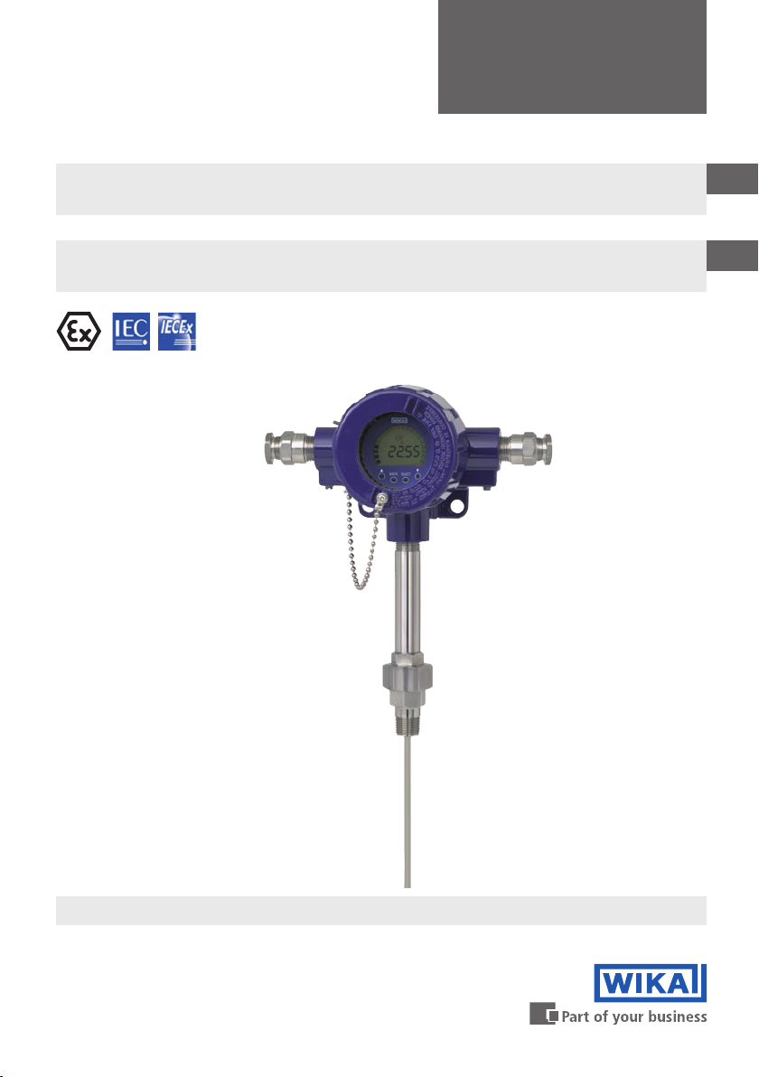
Resistance thermometer TR10-W and thermocouple TC10-W
Ignition protection type Ex d ameproof enclosure per 94/9/EC (ATEX)
Widerstandsthermometer TR10-W und Thermoelement TC10-W
Zündschutzart druckfeste Kapselung Ex d nach 94/9/EC (ATEX)
Ex d BVS 07 ATEX E 071 X
IECEx BVS 11.0042X
GB
D
Models TR10-W, TC10-W
Page 2

GB
Operating instructions models TR10-W, TC10-W (Ex d) Page 3 - 26
D
Betriebsanleitung Typen TR10-W, TC10-W (Ex d) Seite 27 - 50
© 2012 WIKA Alexander Wiegand SE & Co. KG
All rights reserved. / Alle Rechte vorbehalten.
WIKA® is a registered trademark in various countries.
WIKA® ist eine geschützte Marke in verschiedenen Ländern.
Prior to starting any work, read the operating instructions!
Keep for later use!
Vor Beginn aller Arbeiten Betriebsanleitung lesen!
Zum späteren Gebrauch aufbewahren!
2
WIKA operating instructions models TR10-W, TC10-W (Ex d)
14030069.02 03/2014 GB/D
Page 3
Contents
Contents
1. General information 4
2. Safety 5
3. Specications 9
4. Design and function 12
5. Transport, packaging and storage 15
6. Commissioning, operation 16
7. Information on mounting and operation in hazardous
areas 16
8. Safety-related instructions for the dierent variants 18
9. Calculation examples for self-heating at the thermowell tip 21
10. Maintenance and cleaning 23
11. Faults 24
GB
12. Dismounting, return and disposal 25
Appendix: EC declaration of conformity 26
Declarations of conformity can be found online at www.wika.com.
14030069.02 03/2014 GB/D
WIKA operating instructions models TR10-W, TC10-W (Ex d) 3
Page 4

1. General information
1. General information
■
The thermometers described in the operating instructions have been designed and
manufactured using state-of-the-art technology. All components are subject to stringent
GB
quality and environmental criteria during production. Our management systems are
certied to ISO 9001 and ISO 14001.
■
These operating instructions contain important information on handling the instrument.
Working safely requires that all safety instructions and work instructions are observed.
■
Observe the relevant local accident prevention regulations and general safety
regulations for the instrument's range of use.
■
The operating instructions are part of the product and must be kept in the immediate
vicinity of the instrument and readily accessible to skilled personnel at any time.
■
Skilled personnel must have carefully read and understood the operating instructions
prior to beginning any work.
■
The manufacturer's liability is void in the case of any damage caused by using the
product contrary to its intended use, non-compliance with these operating instructions,
assignment of insuciently qualied skilled personnel or unauthorised modications to
the instrument.
■
The general terms and conditions contained in the sales documentation shall apply.
■
Subject to technical modications.
■
Further information:
- Internet address:
- Relevant data sheet:
www.wika.de / www.wika.com
TE 60.14 (TR10-W), TE 65.14 (TC10-W)
- Application consultant: Tel.: +49 9372 132-0
Fax: +49 9372 132-406
info@wika.com
Explanation of symbols
WARNING!
... indicates a potentially dangerous situation that can result in serious injury or
death, if not avoided.
CAUTION!
... indicates a potentially dangerous situation that can result in light injuries or
damage to equipment or the environment, if not avoided.
WIKA operating instructions models TR10-W, TC10-W (Ex d)4
14030069.02 03/2014 GB/D
Page 5
1. General information / 2. Safety
Information
... points out useful tips, recommendations and information for ecient and
trouble-free operation.
DANGER!
... identies hazards caused by electrical power. Should the safety instructions
not be observed, there is a risk of serious or fatal injury.
WARNING!
... indicates a potentially dangerous situation in the hazardous area that can
result in serious injury or death, if not avoided.
WARNING!
... indicates a potentially dangerous situation that can result in burns, caused by
hot surfaces or liquids, if not avoided.
Abbreviations
RTD “Resistance temperature detector”; resistance thermometer
TC Thermocouple
2. Safety
WARNING!
Before installation, commissioning and operation, ensure that the appropriate
thermometer has been selected in terms of measuring range, design and
specic measuring conditions.
Non-observance can result in serious injury and/or damage to the equipment.
GB
Further important safety instructions can be found in the individual chapters of
these operating instructions.
2.1 Intended use
Thermometers in this series can be combined with a large number of thermowell designs.
Operation without thermowell is only recommended in certain applications. A wide variety
of possible combinations of sensor, connection head, insertion length, neck length,
connection to thermowell etc. are available for the thermometers; suitable for almost any
thermowell dimension.
14030069.02 03/2014 GB/D
WIKA operating instructions models TR10-W, TC10-W (Ex d) 5
Page 6
2. Safety
The instrument has been designed and built solely for the intended use described here, and
may only be used accordingly.
The technical specications contained in these operating instructions must be observed.
Improper handling or operation of the instrument outside of its technical specications
GB
requires the instrument to be taken out of service immediately and inspected by an
authorised WIKA service engineer.
If the instrument is transported from a cold into a warm environment, the formation of
condensation may result in instrument malfunction. Before putting it back into operation,
wait for the instrument temperature and the room temperature to equalise.
The manufacturer shall not be liable for claims of any type based on operation contrary to
the intended use.
2.2 Personnel qualication
WARNING!
Risk of injury should qualication be insucient!
Improper handling can result in considerable injury and damage to equipment.
■
The activities described in these operating instructions may only be carried
out by skilled personnel who have the qualications described below.
■
Keep unqualied personnel away from hazardous areas.
Skilled personnel
Skilled personnel are understood to be personnel who, based on their technical training,
knowledge of measurement and control technology and on their experience and knowledge
of country-specic regulations, current standards and directives, are capable of carrying out
the work described and independently recognising potential hazards.
Special operating conditions require further appropriate knowledge, e.g. of aggressive
media.
WIKA operating instructions models TR10-W, TC10-W (Ex d)6
14030069.02 03/2014 GB/D
Page 7
2. Safety
2.3 Special hazards
WARNING!
Observe the information given in the applicable type examination certicate and
the relevant country-specic regulations for installation and use in hazardous
areas (e.g. IEC 60079-14, NEC, CEC). Non-observance can result in serious
injury and/or damage to the equipment.
For further important safety instructions for instruments with ATEX approval, see
chapter 7 “Information on mounting and operation in hazardous areas”.
WARNING!
For hazardous media such as oxygen, acetylene, ammable or toxic gases or
liquids, and refrigeration plants, compressors, etc., in addition to all standard
regulations, the appropriate existing codes or regulations must also be followed.
WARNING!
Protection from electrostatic discharge (ESD) required!
The proper use of grounded work surfaces and personal wrist straps is required
when working with exposed circuitry (printed circuit boards), in order to prevent
static discharge from damaging sensitive electronic components.
To ensure safe working on the instrument, the operating company must ensure
■
that suitable rst-aid equipment is available and aid is provided whenever
required.
■
that the operating personnel are regularly instructed in all topics regarding
work safety, rst aid and environmental protection and know the operating
instructions and in particular, the safety instructions contained therein.
GB
WARNING!
Residual media in the dismounted instrument can result in a risk to persons, the
environment and equipment. Take sucient precautionary measures.
Do not use this instrument in safety or emergency stop devices. Incorrect use of
the instrument can result in injury.
Should a failure occur, aggressive media with extremely high temperature and
under high pressure or vacuum may be present at the instrument.
14030069.02 03/2014 GB/D
WIKA operating instructions models TR10-W, TC10-W (Ex d) 7
Page 8
TR10-W
1 x Pt100 / A / 3 (F) -50 ... +500 °C
Um = DC 30 V / Pm = 2 W
BVS 07 ATEX E 071 X
IECEx BVS 11.0042X
II 2 G Ex d IIC T* Gb
EN 60751
0158
WIKA Alexander Wiegand SE & Co.KG, D-63911 Klingenberg
Made in Germany 2013
WARNING: DO NOT OPEN WHILE ENERGIZED!
11012345
2. Safety
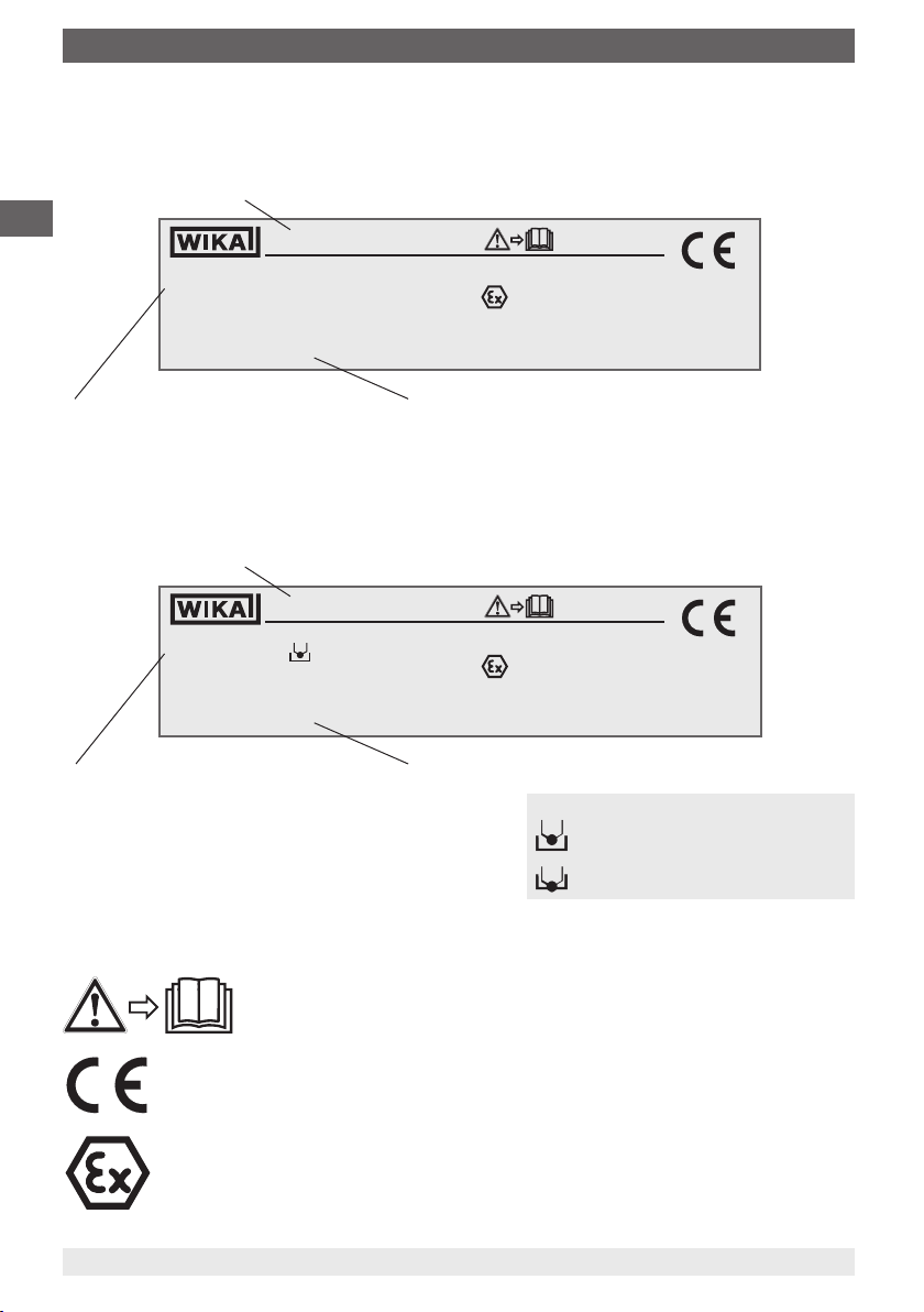
2.4 Labelling, safety marking
2.4.1 Product labels for resistance thermometers
Model
GB
TR10-W
1 x Pt100 / A / 3 (F) -50 ... +500 °C
Um = DC 30 V / Pm = 2 W
WIKA Alexander Wiegand SE & Co.KG, D-63911 Klingenberg
Made in Germany 2013
EN 60751
11012345
BVS 07 ATEX E 071 X
IECEx BVS 11.0042X
II 2 G Ex d IIC T* Gb
WARNING: DO NOT OPEN WHILE ENERGIZED!
0158
Sensor in accordance with standard
■
F Thin-lm measuring resistor
■
W Wire-wound measuring resistor
2.4.2 Product labels for thermocouples
Model
TC10-W
1 x Typ K / 1 / . 0 ... +600 °C
Um = DC 30 V / Pm = 2 W
WIKA Alexander Wiegand SE & Co.KG, D-63911 Klingenberg
Made in Germany 2013
Sensor in accordance with standard
■
ungrounded
■
grounded
Explanation of symbols
CE, Communauté Européenne
Instruments bearing this mark comply with the relevant European directives.
ATEX European Explosion Protection Directive
(Atmosphère = AT, explosible = EX)
Instruments bearing this mark comply with the requirements of the European
directive 94/9/EC (ATEX) on explosion protection.
Before mounting and commissioning the instrument, ensure you read
the operating instructions!
Year of manufacture
EN 60584-1
WARNING: DO NOT OPEN WHILE ENERGIZED!
Year of manufacture
WIKA operating instructions models TR10-W, TC10-W (Ex d)8
11012345
BVS 07 ATEX E 071 X
IECEx BVS 11.0042X
II 2 G Ex d IIC T* Gb
Legend:
■
ungrounded
ungrounded welded
■
grounded
welded to the sheath (grounded)
0158
14030069.02 03/2014 GB/D
Page 9

3. Specications
3. Specications
3.1 Resistance thermometer
Sensor connection method
■
2-wire
■
3-wire
■
4-wire
Sensor tolerance value per DIN EN 60751
■
Class B
■
Class A
■
Class AA
The combinations of a 2-wire connection with class A or class AA are not permissible, since
the lead resistance of the measuring insert negates the higher sensor accuracy.
Basic values and tolerance values
Basic values and tolerance values for the platinum measurement resistances are laid down
in DIN EN 60751.
The nominal value of Pt100 sensors is 100 Ω at 0 °C. The temperature coecient α can be
stated simply to be between 0 °C and 100 °C with:
-3
α = 3.85 ∙ 10
°C
-1
The relationship between temperature and electrical resistance is described by
polynomials, which are also dened in DIN EN 60751. Moreover, this standard species the
basic values in °C steps in tabular form.
Class
B -196 … +600 °C -50 … +500 °C ±(0.30 + 0.0050 | t |)
A -100 … +450 °C -30 … +300 °C ±(0.15 + 0.0020 | t |)
AA -50 … +250 °C 0 … 150 °C ±(0.10 + 0.0017 | t |)
Temperature range
Wire-wound (W) Thin-lm (F)
Tolerance value in °C
1)
1)
1)
GB
1) | t | is the value of the temperature in °C without consideration of the sign.
Bold: Standard version
For further technical information, see WIKA data sheet and the Technical information
IN 00.17 “Usage limitations and accuracies of platinum resistance thermometers per
EN 60751: 2008”.
14030069.02 03/2014 GB/D
WIKA operating instructions models TR10-W, TC10-W (Ex d) 9
Page 10

3. Specications
3.2 Thermocouples
3.2.1 Sensor types
Type
K 1,200 °C
GB
J 800 °C
E 800 °C
N 1,200 °C
3.2.2 Potential measurement uncertainties
Important factors which counteract the long-term stability of thermocouples.
Ageing eects/poisoning
■
Oxidation processes in thermocouples which are not appropriately protected (“bare”
thermocouple wires) result in falsications of the characteristic curves.
■
Foreign atoms (poisoning) that diuse into the original alloys lead to changes of these
original alloys and thus falsify the characteristic curve.
■
The inuence of hydrogen leads to the embrittlement of the thermocouples.
The Ni leg of the type K thermocouple is often damaged by sulphur which is contained in
exhaust gases, for example. Type J and T thermocouples age slightly, as the pure metal leg
oxidises rst.
Recommended max. operating temperature
In general, rising temperatures cause accelerated ageing eects.
Green rot
If type K thermocouples are used at temperatures from approx. 800 °C to 1,050 °C,
considerable changes of the thermoelectric voltage can occur. The cause of this is a
chromium depletion or the chrome oxidation in the NiCr leg (+ leg). The precondition
for this is a low concentration of oxygen or steam in the immediate environment of the
thermocouple. The nickel leg is not aected by it. The consequence of this eect is a drift of
the measured value caused by decreasing thermoelectric voltage. This eect is accelerated
if there is a shortage of oxygen (reducing atmosphere), since a complete oxide layer, which
would protect it from further oxidation of the chromium, cannot be formed on the surface of
the thermocouple.
The thermocouple is permanently destroyed by this process. The name green rot is derived
from the greenish shimmering colouration on the breaking point of the wire.
The thermocouple type N has in this regard an advantage due to its silicium content. Here,
a protective oxide layer forms on its surface under the same conditions.
WIKA operating instructions models TR10-W, TC10-W (Ex d)10
14030069.02 03/2014 GB/D
Page 11

3. Specications
K eect
The NiCr leg of a type K thermocouple has an ordered alignment with respect to the
alignment in the crystal lattice below approx. 400 °C. If the thermocouple is heated further,
a transition to a disordered state occurs in the temperature range between approx. 400 °C
and 600 °C. Above 600 °C, an ordered crystal lattice is restored.
If these thermocouples cool too quickly (quicker than approx. 100 °C per hour), the
undesirable disordered crystal lattice occurs again during cooling in the range from
approx. 600 °C to approx. 400 °C. In the characteristic curve of type K, however, a
consistently ordered alignment state is assumed and provided with values. This results
in a fault of thermoelectric voltage of up to approx. 0.8 mV (approx. 5 °C) in this range.
The K eect is reversible and is largely eliminated again by annealing above 700 °C,
followed by correspondingly slow cooling.
Thin sheathed thermocouples are particularly sensitive in this regard. Cooling in resting air
can already lead to deviations of 1 °C.
In type N thermocouples, it has been possible to reduce this short-range-order eect by
alloying both legs with silicium.
The application range of these thermometers is limited both by the permissible maximum
temperature of the thermocouple and by the permissible maximum temperature of the
thermowell material.
Listed models are available both as single or dual thermocouples. The thermocouple will be
delivered with an insulated measuring point, unless explicitly specied otherwise.
GB
Tolerance value
For the tolerance value of thermocouples, a cold junction temperature of 0 °C has been
taken as the basis. When using a compensating cable or thermocouple cable, an additional
measuring deviation must be considered.
For tolerance values and further specications, see the corresponding WIKA data sheet
and Technical information IN 00.23, “Application of thermocouples”.
For further specications see WIKA data sheets TE 60.14, TE 65.14 and order
documentation.
For further important safety instructions for operation in hazardous areas, see
chapter 7 “Information on mounting and operation in hazardous areas”.
14030069.02 03/2014 GB/D
WIKA operating instructions models TR10-W, TC10-W (Ex d) 11
Page 12
4. Design and function
4. Design and function
4.1 Resistance thermometer model TR10-W
The resistance thermometers of model TR10-W consist of a ameproof enclosure, a
measuring insert which is mounted elastically in a neck tube. The measuring insert in
GB
connection with the neck tube functions as a amepath. The choice of the housing to be
mounted and installed is dened by the WIKA housing/instrument list. When applying it,
always use the latest revision of it.
The thermometers are designed to be resistant to shock and vibration and all electrical
components are protected against splash water. The vibration resistance of the standard
version corresponds to DIN EN 60751 (up to 3 g). The impact resistance of all versions
meets the requirements of DIN EN 60751.
The electrical connection is performed using Ex d certied components.
CAUTION!
Resistance thermometers of this model range must be installed with a
thermowell (minimal wall thickness: 1 mm). The design of the thermowells can
be selected optionally, but the operational process data (temperature, pressure,
density and ow rate) must be taken into account.
Possible sensor measuring ranges: from -200 … +600 °C
4.2 Thermocouple model TC10-W
The thermocouples of model TC10-W consist of a ameproof enclosure, a measuring insert
which is mounted elastically in a neck tube. The measuring insert in connection with the
neck tube functions as a amepath. The choice of the housing to be mounted and installed
is dened by the WIKA housing/instrument list. When applying it, always use the latest
revision of it.
The thermometers are designed to be resistant to shock and vibration and all electrical
components are protected against splash water.
The electrical connection is performed using Ex d certied components.
CAUTION!
Thermocouples of this model range must be installed with a thermowell
(minimal wall thickness: 1 mm). The design of the thermowells can be selected
as desired, but the operational process data (temperature, pressure, density
and ow rate) must be taken into account.
Possible measuring ranges: from -200 … +1.200 °C
The following mounting and operating information has been compiled with care. However, it
is not possible to consider all potential usage cases.
WIKA operating instructions models TR10-W, TC10-W (Ex d)12
14030069.02 03/2014 GB/D
Page 13

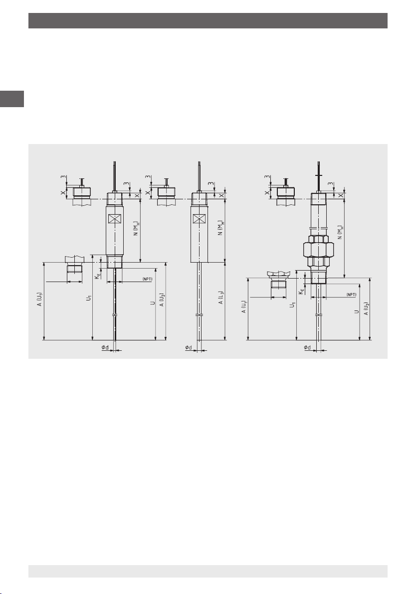
4. Design and function
4.3 Technical description of the three variants
Variant 1: ATEX/IECEx-Ex d
housing or connection head
(with connection terminals,
without transmitter)
Variant 2: ATEX/IECEx-Ex d
housing or connection head
(with built-in head-mounted
transmitter)
Variant 3: ATEX/IECEx-
Ex d certied temperature
transmitter
GB
T4
T3
T1
Thread
T4: {-50} -40 °C < Ta < +85 °C
T3: {-50} -40 °C < Ta < +150 °C
T1: {-50} -40 °C < Ta < +300 °C
Thread
Legend:
Connection head
Neck tube
Connection to thermowell
Thread
Measuring insert
Terminal block/transmitter (option)
Field transmitter
T
undened
Variant 1:
The thermometer is tted to a certied enclosure with ignition protection type “ameproof
enclosure”, which has a built-in terminal block. If the thermometer is marked with II 2G Ex d
IIC T1-T6 Gb, it is designed for use in zone 1 with a thermowell.
If the thermometer is marked with II 1/2G Ex d IIC T1-T6 Ga/Gb, then it is designed for use
with a thermowell at the partition to zone 0.
Variant 2:
The thermometer is built into a certied enclosure, with an ignition protection type of
“ameproof enclosure”, in which an electronic assembly has been tted.
If the thermometer is marked with II 2G Ex d IIC T1-T6 Gb, it is designed for use in zone 1
with a thermowell.
If the thermometer is marked with II 1/2G Ex d IIC T1-T6 Ga/Gb, then it is designed for use
with a thermowell at the partition to zone 0.
14030069.02 03/2014 GB/D
WIKA operating instructions models TR10-W, TC10-W (Ex d) 13
Page 14
4. Design and function
Variant 3:
The thermometer is tted to certied equipment (transmitter) with an ignition protection type
of “ameproof enclosure”.
The thermometer is marked with II 2G Ex d IIC Gb and is designed for use in zone 1 with
a thermowell. For any potential usage at the partition to zone 0 with a thermowell, the
GB
approvals and conditions of the relevant transmitters must be considered.
4.4 Neck tube versions
xed design
multi-part design
11401940.01
Thread
Thread
Thread
Thread
4.5 Housing- and connection heads
The dimensions of the housing- and connection heads are given in the respective data
sheet.
4.6 Scope of delivery
Cross-check scope of delivery with delivery note.
WIKA operating instructions models TR10-W, TC10-W (Ex d)14
14030069.02 03/2014 GB/D
Page 15
5. Transport, packaging and storage
5. Transport, packaging and storage
5.1 Transport
Check the instrument for any damage that may have been caused by transport.
Obvious damage must be reported immediately.
5.2 Packaging
Do not remove packaging until just before mounting.
Keep the packaging as it will provide optimum protection during transport (e.g. change in
installation site, sending for repair).
5.3 Storage
Permissible conditions at the place of storage:
■
Storage temperature: {-50} -40 ... +80 °C
■
Humidity: 35 ... 85 % relative humidity (no condensation)
Avoid exposure to the following factors:
■
Direct sunlight or proximity to hot objects
■
Mechanical vibration, mechanical shock (putting it down hard)
■
Soot, vapour, dust and corrosive gases
■
Potentially explosive environments, ammable atmospheres
Store the instrument in its original packaging in a location that fulls the conditions listed
above. If the original packaging is not available, pack and store the instrument as described
below:
1. Wrap the instrument in an antistatic plastic lm.
2. Place the instrument along with shock-absorbent material in the packaging.
3. If stored for a prolonged period of time (more than 30 days), place a bag containing a
desiccant inside the packaging.
GB
WARNING!
Before storing the instrument (following operation), remove any residual media.
This is of particular importance if the medium is hazardous to health, e.g.
caustic, toxic, carcinogenic, radioactive, etc.
14030069.02 03/2014 GB/D
WIKA operating instructions models TR10-W, TC10-W (Ex d) 15
Page 16
6. Commissioning, operation / 7. Information on mounting ...
6. Commissioning, operation
6.1 Electrical connection
Variant 1
GB
For the electrical specications (e.g. connection diagrams, tolerance values, etc.) please
refer to the data sheets TE 60.14 (for TR10-W) and TE 65.14 (for TC10-W).
Variant 2
For the electrical specications (e.g. connection diagrams, tolerance values etc.), refer to
the corresponding data sheet of the built-in head-mounted transmitters.
Variant 3
For the electrical specications (e.g. connection diagrams, tolerance values etc.), refer to
the corresponding data sheet of the tted Ex d certied eld transmitters.
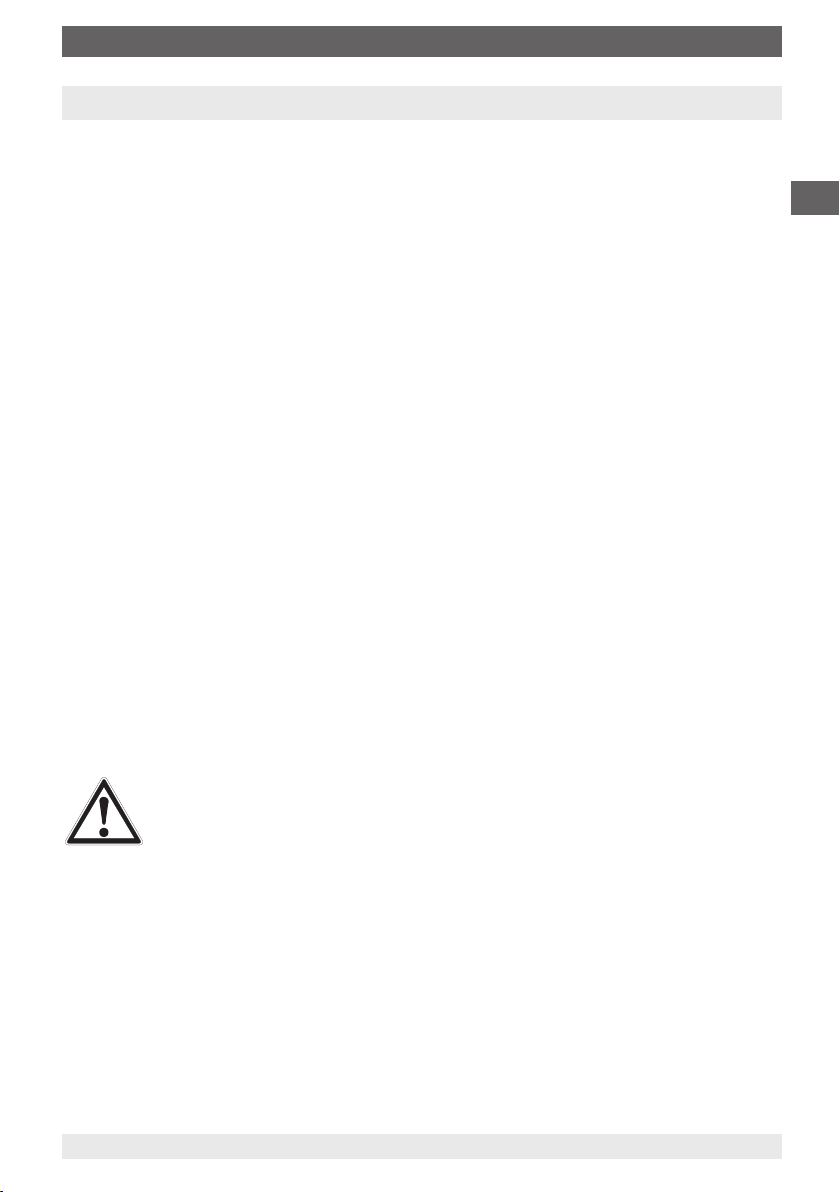
6.2 Locking screw
Always tighten the locking screw to prevent unintended opening of
the head with ameproof enclosure.
Before opening the head, always loosen the locking screw
suciently.
7. Information on mounting and operation in hazardous areas
WARNING!
Non-observance of these instructions and their contents may result in the loss
of explosion protection.
The requirements of the 94/9/EC (ATEX) directive must be followed. Additionally
the specications of the respective national regulations concerning Ex usage
(e.g. EN/IEC 60079-10 and EN/IEC 60079-14) apply.
■
The responsibility for classication of zones lies with the plant operator and not the
manufacturer/supplier of the equipment.
■
The plant operator guarantees, and is solely responsible, that all thermometers in use
are identiable with respect to all safety-relevant characteristics. Damaged thermometers
may not be used.
■
For the installation of the thermometer, only components (e.g. cables, cable glands, etc.)
permitted for “ameproof” may be used.
■
For earthing the conductive screen, follow the specications of EN/IEC 60079-14.
WIKA operating instructions models TR10-W, TC10-W (Ex d)16
14030069.02 03/2014 GB/D
Page 17

7. Information on mounting and operation in hazardous areas
■
When using a transmitter/digital display, note and follow:
- The contents of these operating instructions and those of the transmitter/digital display
- The relevant regulations for installation and use of electrical systems
- The regulation and guidelines regarding explosion protection
■
The certied ameproof thermometers should only be tted to housing- or connection
heads certied with a “ameproof” ignition protection type.
■
Certied and listed eld cases (variant 3) should only be tted and installed by a
specialist trained to the latest technology.
■
For tting, the permitted ameproof joints for electrical equipment for gas hazardous
areas are contained in EN/IEC 60079-1. Flameproof joints (section 5.3) for parallel
threads (in accordance with table 3), must be ≥ 5 mm for housing volumes < 100 cm³
and ≥ 8 mm for housing volumes > 100 cm³. There must be ≥ 5 threads engaged.
Flameprooof joints (section 5.3) for tapered threads (in accordance with table 3), must
have ≥ 5 available threads on each part. There must be ≥ 3.5 threads engaged.
These specications for ameproof joints must be adhered to, without fail, when tting
and during operation.
■
The direct threaded connection of the thermometer to the connection head or housing
must not be twisted or opened. Any alignment of the housing may only be made using
the optional “nipple-union-nipple” neck tube.
■
The temperature resistance of the connecting cable must match the permissible
operating temperature of the housing.
For ambient temperatures above 60 °C, heat-resistant connecting cable must be used.
■
No batteries may be built in to the ameproof housing.
■
No capacitor may be tted within the ameproof housing that has a residual energy of
≥ 0.02 mJ at the end of the time required to open the housing. The housing must not be
opened during operation. After the power supply has been switched o, a waiting time of
2 minutes must be observed before opening the housing.
■
Mounting within metallic enclosures:
The housing must be grounded against electromagnetic elds and electrostatic
discharge. It does not have to be connected separately to the equipotential bonding
system. It is sucient if the metallic thermowell has a solid and secured contact with the
metallic vessel or its structural components or pipelines, so long as these components
are connected to the equipotential bonding system.
■
Fitting in non-metallic vessels:
All electrically-conductive thermometer components within the hazardous area must be
provided with equipotential bonding.
■
Neither repairs nor structural modications are permitted, and any would void the
guarantee and the respective certication.
■
The manufacturer shall not be responsible for constructional modications after delivery
of the instruments.
GB
14030069.02 03/2014 GB/D
WIKA operating instructions models TR10-W, TC10-W (Ex d) 17
Page 18

8. Safety-related instructions for the dierent variants
8. Safety-related instructions for the dierent variants
8.1 Variant 1:
ATEX/IECEx-Ex d housing or connection head (with connection terminals, without transmitter)
Evaluation of the resistance or the thermoelectric potential between electronics outside of
GB
the hazardous area.
Use in zone 1, marking II 2G Ex d IIC T1-T6 Gb
The ameproof housing or the connection head is in zone 1 (or zone 2). The sensor is within
a thermowell (made of corrosion resistant steel, min. wall thickness 1 mm) which extends
into zone 1 via a process connection. In this case, no power limitation is needed, since no
error monitoring is performed by the electronic evaluation system.
Use with a thermowell at the partition to zone 0, marking II 1/2G Ex d IIC T1-T6 Ga/Gb
The ameproof housing or the connection head is in zone 1 (or zone 2). The sensor is
within a thermowell (min. wall thickness 1 mm) which extends into zone 0 via a process
connection.
The thermometer should therefore be operated with a power-limiting circuit.
P
: 2 W U
max
A power supply with Ex ia circuitry fullls these conditions, but is not required if the limits
can be achieved through other measures. The responsibility rests with the operator.
Temperature class classication, ambient temperatures
Ambient temperature range for all WIKA connection heads: -40 … +85 °C
The permissible ambient temperatures for third-party products can be seen from the
relevant approvals and/or data sheets.
A heating in the connection head does not occur with varient 1. However, an impermissible
heat reux from the process which can exceed the operating temperature of the housing or
the temperature class, must be prevented through suitable heat insulation or a suitably long
neck tube.
max
: 30 V
8.2 Variant 2:
ATEX/IECEX-Ex d housing or connection head with built-in head-mounted transmitter
The evaluation is performed using current (4 … 20 mA), voltage (2 … 10 V) or eldbus
signal, which is generated by a head-mounted transmitter.
Use in zone 1, marking II 2G Ex d IIC T1-T6 Gb
The ameproof housing or the connection head is in zone 1 (or zone 2). The sensor is
within a thermowell (min. wall thickness 1 mm) which extends into zone 1 via a process
connection.
WIKA operating instructions models TR10-W, TC10-W (Ex d)18
14030069.02 03/2014 GB/D
Page 19

8. Safety-related instructions for the dierent variants
Use with a thermowell at the partition to zone 0, marking II 1/2G Ex d IIC T1-T6 Ga/Gb
The ameproof housing or the connection head is in zone 1 (or zone 2). The sensor is
within a thermowell (min. wall thickness 1 mm) which extends into zone 0 via a process
connection.
The thermometer should be operated with a power-limiting circuit.
P
: 2 W U
max
A power supply with Ex ia circuits meets these conditions, but is not required if the limits
can be achieved with other measures. The responsibility rests with the operator.
WIKA recommends realising the power limitation through a suitable fuse in the 4 ... 20 mA
current loop of the head-mounted transmitter. In the event of a failure of the head-mounted
transmitter, the circuit will be interrupted through the fuse tripping.
Example for calculating the fuse for a maximum power at the sensor of 0.8 Watt:
The internal resistance of thermocouples is signicantly lower than the thermal resistance
of a Pt100 sensor, so the much less favourable case for a resistance thermometer has been
calculated.
P
= (1.7 x Is)² x R
all
Is = Fuse rating
P
= maximum power at sensor = 0.8 W
all
R
= Resistance of the sensor (temperature-dependent)
w
at 450 °C = 264.18 Ω in accordance with DIN EN 60751 for Pt100
The following denes the fuse rating:
I
= sqrt (P
s
I
= sqrt (0.8 W / 265 Ω) / 1.7
s
I
= 32.32 mA
s
all
This results in a rated current for a fuse link = 32 mA
: 30 V
max
w
/ Rw) / 1.7
GB
Notes for fuse calculation:
The next smallest fuse value, in accordance with IEC 60127, must always be chosen. The
breaking capacity must be matched, by sensible engineering, to the voltage supply. Usual
values for such fuse links lie between AC 20 A and AC 80 A rated breaking capacity.
For a maximum power at the sensor of 0.5 W the following value is given:
I
= sqrt (0.5 W / 265 Ω) / 1.7
s
I
= 25.55 mA
s
This results in a rated current for a fuse link = 25 mA
When using multiple sensors and simultaneous operation, the sum of the individual powers
must not exceed the value of the maximum permissible power.
Internal resistance of Ø 6 mm TC measuring inserts: approx. 1.2 Ω/m
Internal resistance of Ø 3 mm TC measuring inserts: approx. 5.6 Ω/m
These measured values are valid for room temperature.
14030069.02 03/2014 GB/D
WIKA operating instructions models TR10-W, TC10-W (Ex d) 19
Page 20

8. Safety-related instructions for the dierent variants
Temperature class classication, ambient temperatures
A heating in the connection head can occur with variant 2 through faulty electronics. The
permissible ambient temperatures depend on the housing used and any additionally-tted
head-mounted transmitter.
GB
For all WIKA connection heads with built-in WIKA temperature transmitters, the
following interrelation is valid:
The temperature increase on the surface of the connection head or housing is less than
25 K if the following conditions are observed: power supply U
transmitter is operated in a current limit of 22.5 mA.
This yields the following temperature class classication.
Temperature class Ambient temperature
T6 -40 … +55 °C
T5 -40 … +75 °C
T4, T3, T2, T1 -40 … +85 °C
The permissible ambient temperatures for third-party products can be seen from the
relevant approvals or data sheets. However, an impermissible heat reux from the process
which can exceed the operating temperature of the housing or the temperature class, must
be prevented through suitable heat insulation or a suitably long neck tube.
8.3 Variant 3
ATEX/IECEx Ex d certied temperature transmitters.
The evaluation is performed using current (4 … 20 mA), voltage (2 … 10 V) or eldbus
signal, which is generated by an ATEX/IECEx Ex d certied temperature transmitter.
maximum DC 30 V when the
B
Use in zone 1, marking II 2G Ex d IIC Gb
The Ex d eld transmitter is located in zone 1 (or zone 2). The sensor is within a thermowell
(min. wall thickness 1 mm) which extends into zone 1 via a process connection.
The main Ex marking is located on the certied Ex d eld transmitter. The TR10-W and
TC10-W instruments are marked with a foil plate on the neck tube.
For a possible use at the partition to zone 0 with a thermowell, the approvals and conditions
of the relevant Ex d eld transmitters must be followed.
Temperature class classication, ambient temperatures
Ambient temperature range for the measuring insert with neck tube: -40 … +85 °C.
The permissible ambient temperatures of the certied Ex d eld transmitter must be taken
from the respective operating instructions or data sheets. Through deviations in temperature
ranges, limitations can occur.
WIKA operating instructions models TR10-W, TC10-W (Ex d)20
14030069.02 03/2014 GB/D
Page 21

9. Calculation examples for self-heating at the thermowell tip
9. Calculation examples for self-heating at the thermowell tip
The self-heating at the thermowell tip depends upon the sensor type (measuring resistor/
thermocouple), the measuring insert diameter and the thermowell design. The table below
shows the possible combinations. The heating at the sensor tip of the bare measuring
insert is clearly higher; the representation of these values was omitted on the grounds
of the required assembly with a thermowell. The table shows that when a failure occurs,
thermocouples produce much less self-heating than resistance thermometers.
GB
Thermal resistance [R
in K/W]
th
Measuring insert diameter 3 mm 6 mm 3 mm 6 mm
Sensor type RTD RTD TC TC
With fabricated thermowell
(straight and tapered)
(e.g. TW30, TW35, TW40)
With solid material thermowell (straight and tapered)
(e.g. TW10, TW15, TW20, TW25, TW30)
Installed in a blind bore
(minimum wall thickness 5 mm)
60 37 15 5
22 16 10 3
22 16 10 3
9.1 Example calculation for variant 2, resistance thermometer
Use at the partition to zone 0, marking II 1/2G Ex d IIC T1-T6 power-limited circuit using a
fuse with 32 mA.
Calculate the maximum permissible temperature T
at the thermowell tip for the following
max
combination:
Ø 6 mm RTD measuring insert with built-in head-mounted transmitter, assembled with solid
material thermowell.
T
is obtained by adding the temperature of the medium and the self-heating. The
max
self-heating depends on the supplied power P
calculated supplied power, P
, comes from the chosen standard value for the fuse and is
o
and the thermal resistance Rth. The
o
only realised at the sensor tip.
It thus gives the following formula: T
T
= Surface temperature (max. temperature at the thermowell tip)
max
P
= 0.8 W (fuse with 32 mA, a complete short-circuit of the transmitter is assumed)
o
R
= Thermal resistance [K/W]
th
T
= Temperature of the medium
M
= Po x Rth + T
max
M
14030069.02 03/2014 GB/D
WIKA operating instructions models TR10-W, TC10-W (Ex d) 21
Page 22

9. Calculation examples for self-heating at the thermowell tip
Example: Resistance thermometer
Diameter: 6 mm
Temperature of the medium: T
Supplied power: P
Temperature class T3 (200 °C) must not be exceeded
GB
Thermal resistance [R
= 0.8 W
o
in K/W] from table = 16 K/W
th
Self-heating: 0.8 W x 16 K/W = 12.8 K
T
= TM + self-heating: 150 °C + 12.8 °C = 162.8 °C
max
As safety margin for type-examined instruments (for T6 to T3), an additional 5 °C must be
subtracted from the 200 °C; hence 195 °C would be permissible. This means that in this
case temperature class T3 is not exceeded.
Additional information:
Temperature class for T3 = 200 °C
Safety factor for type-tested instruments (for T6 to T3)
Safety factor for type-tested instruments (for T1 to T2)
Safety factor for applications for instrument category 1 (zone 0)
application here.
1) EN 60079-0 / EN 60079-1
2) EN 60079-26
9.2 Example calculation for variant 2, thermocouple
Under the same conditions it gives a lower value for the self-warming, since the supplied
power is not only converted at the sensor tip, but rather over the entire length of the
measuring insert.
= 150 °C
M
1)
= 5 K
1)
= 10 K
2)
= 80 % nds no
Thermal resistance [R
in K/W] from table = 3 K/W
th
Self-heating: 0.8 W x 3 K/W = 2.4 K
T
= TM + self-heating: 150 °C + 2.4 °C = 152.4 °C
max
As safety margin for type-examined instruments (for T6 to T3), an additional 5 °C must be
subtracted from the 200 °C; hence 195 °C would be permissible. This means that in this
case temperature class T3 is not exceeded.
In this example it is clear that the self-heating here is almost negligible.
WIKA operating instructions models TR10-W, TC10-W (Ex d)22
14030069.02 03/2014 GB/D
Page 23

10. Maintenance and cleaning
10. Maintenance and cleaning
10.1 Maintenance
The thermometers described here are maintenance-free.
Repairs must only be carried out by the manufacturer.
10.2 Cleaning
CAUTION!
■
Prior to cleaning, switch o and disconnect the instrument from the mains.
■
Clean the instrument with a moist cloth.
■
Electrical connections must not come into contact with moisture.
■
Wash or clean the dismounted instrument before returning it, in order to
protect persons and the environment from exposure to residual media.
■
Residual media in the dismounted instrument can result in a risk to persons,
the environment and equipment.
Take sucient precautionary measures.
For information on returning the instrument see chapter 12.2 “Return”.
10.3 Calibration, recalibration
It is recommended that the measuring insert is recalibrated at regular intervals (resistance
thermometers: approx. 24 months; thermocouples: approx. 12 months). This period can
reduce, depending on the particular application. The calibration can be carried out by the
manufacturer, as well as on site by qualied technical sta with calibration instruments.
GB
14030069.02 03/2014 GB/D
WIKA operating instructions models TR10-W, TC10-W (Ex d) 23
Page 24

11. Faults
11. Faults
Faults Causes Measures
No signal/
GB
line break
Erroneous measured
values
Erroneous measured
values (too low)
Erroneous measured
values and response
times too long
Erroneous measured
values (of thermocouples)
Display of measured
value jumps
Corrosion Composition of the medium not
Signal interference
Mechanical load too high or
overtemperature
Sensor drift caused by overtemperature Replacement of the sensor or the
Sensor drift caused by chemical attack
Entry of moisture into cable or
measuring insert
Wrong mounting geometry, for example
mounting depth too deep or heat
dissipation too high
Deposits on the sensor or thermowell
Parasitic voltages (thermal voltages,
galvanic voltage) or wrong equalisation
line
Cable break in connecting cable or
loose contact caused by mechanical
overload
as expected or modied or wrong
thermowell material selected
Stray currents caused by electric elds
or earth loops
Earth loops Elimination of potentials, use of
Replacement of the sensor or the
measuring insert with a suitable version
measuring insert with a suitable version
Use of a suitable thermowell
Replacement of the sensor or the
measuring insert with a suitable version
The temperature-sensitive area of the
sensor must be inside the medium,
and surfaces measurements must be
ungrounded
Remove deposits
Use of a suitable equalisation line
Replacement of the sensor or
measuring insert with a suitable design,
for example tted with strain relief or a
thicker conductor cross-section
Analyse medium and then select a
more-suitable material or replace
thermowell regularly
Use of screened connecting cables,
increase in the distance to motors and
power lines
galvanically isolated transmitter supply
isolators or transmitters
CAUTION!
If faults cannot be eliminated by means of the measures listed above, the
instrument must be shut down immediately, and it must be ensured that signal
is no longer present, and it must be prevented from being inadvertently put back
into service.
In this case, contact the manufacturer.
If a return is needed, please follow the instructions given in chapter
12.2 “Return”.
WIKA operating instructions models TR10-W, TC10-W (Ex d)24
14030069.02 03/2014 GB/D
Page 25

12. Dismounting, return and disposal
12. Dismounting, return and disposal
WARNING!
Residual media in the dismounted instrument can result in a risk to persons, the
environment and equipment.
Take sucient precautionary measures.
12.1 Dismounting
WARNING!
Risk of burns!
Let the instrument cool down suciently before dismounting it!
During dismounting there is a risk of dangerously hot pressure media escaping.
Only disconnect the thermometer once the system has been depressurised!
12.2 Return
WARNING!
Strictly observe the following when shipping the instrument:
All instruments delivered to WIKA must be free from any kind of hazardous
substances (acids, bases, solutions, etc.).
When returning the instrument, use the original packaging or a suitable transport package.
GB
To avoid damage:
1. Wrap the instrument in an antistatic plastic lm.
2. Place the instrument along with shock-absorbent material in the packaging.
Place shock-absorbent material evenly on all sides of the transport packaging.
3. If possible, place a bag containing a desiccant inside the packaging.
4. Label the shipment as carriage of a highly sensitive measuring instrument.
Information on returns can be found under the heading “Service” on our local
website.
12.3 Disposal
Incorrect disposal can put the environment at risk.
Dispose of instrument components and packaging materials in an environmentally
compatible way and in accordance with the country-specic waste disposal regulations.
14030069.02 03/2014 GB/D
WIKA operating instructions models TR10-W, TC10-W (Ex d) 25
Page 26

Appendix: EC declaration of conformity
GB
14030069.02 03/2014 GB/D
WIKA operating instructions models TR10-W, TC10-W (Ex d)26
Page 27

Inhalt
Inhalt
1. Allgemeines 28
2. Sicherheit 29
3. Technische Daten 33
4. Aufbau und Funktion 36
5. Transport, Verpackung und Lagerung 39
6. Inbetriebnahme, Betrieb 40
7. Hinweise zu Montage und Betrieb im explosionsgefähr-
deten Bereich 40
8. Sicherheitstechnische Hinweise für die verschiedenen
Varianten 42
9. Berechnungsbeispiele für die Eigenerwärmung an der
Schutzrohrspitze 45
10. Wartung und Reinigung 47
11. Störungen 48
12. Demontage, Rücksendung und Entsorgung 49
Anlage: EG-Konformitätserklärung 50
Konformitätserklärungen nden Sie online unter www.wika.de.
D
14030069.02 03/2014 GB/D
WIKA Betriebsanleitung Typen TR10-W, TC10-W (Ex d) 27
Page 28

1. Allgemeines
1. Allgemeines
■
Die in der Betriebsanleitung beschriebenen Thermometer werden nach dem aktuellen
Stand der Technik konstruiert und gefertigt.
Alle Komponenten unterliegen während der Fertigung strengen Qualitäts- und Umweltkriterien. Unsere Managementsysteme sind nach ISO 9001 und ISO 14001 zertiziert.
■
Diese Betriebsanleitung gibt wichtige Hinweise zum Umgang mit dem Gerät. Vorausset-
zung für sicheres Arbeiten ist die Einhaltung aller angegebenen Sicherheitshinweise und
D
Handlungsanweisungen.
■
Die für den Einsatzbereich des Gerätes geltenden örtlichen Unfallverhütungsvorschriften
und allgemeinen Sicherheitsbestimmungen einhalten.
■
Die Betriebsanleitung ist Produktbestandteil und muss in unmittelbarer Nähe des
Gerätes für das Fachpersonal jederzeit zugänglich aufbewahrt werden.
■
Das Fachpersonal muss die Betriebsanleitung vor Beginn aller Arbeiten sorgfältig durchgelesen und verstanden haben.
■
Die Haftung des Herstellers erlischt bei Schäden durch bestimmungswidrige Verwen-
dung, Nichtbeachten dieser Betriebsanleitung, Einsatz ungenügend qualizierten
Fachpersonals sowie eigenmächtiger Veränderung am Gerät.
■
Es gelten die allgemeinen Geschäftsbedingungen in den Verkaufsunterlagen.
■
Technische Änderungen vorbehalten.
■
Weitere Informationen:
- Internet-Adresse:
- zugehöriges Datenblatt:
www.wika.de / www.wika.com
TE 60.14 (TR10-W), TE 65.14 (TC10-W)
- Anwendungsberater: Tel.: +49 9372 132-0
Fax: +49 9372 132-406
info@wika.de
Symbolerklärung
WARNUNG!
… weist auf eine möglicherweise gefährliche Situation hin, die zum Tod oder zu
schweren Verletzungen führen kann, wenn sie nicht gemieden wird.
VORSICHT!
… weist auf eine möglicherweise gefährliche Situation hin, die zu geringfügigen
oder leichten Verletzungen bzw. Sach- und Umweltschäden führen kann, wenn
sie nicht gemieden wird.
WIKA Betriebsanleitung Typen TR10-W, TC10-W (Ex d)28
14030069.02 03/2014 GB/D
Page 29

1. Allgemeines / 2. Sicherheit
Information
… hebt nützliche Tipps und Empfehlungen sowie Informationen für einen ezienten und störungsfreien Betrieb hervor.
GEFAHR!
… kennzeichnet Gefährdungen durch elektrischen Strom. Bei Nichtbeachtung
der Sicherheitshinweise besteht die Gefahr schwerer oder tödlicher Verletzungen.
WARNUNG!
… weist auf eine möglicherweise gefährliche Situation im explosionsgefährdeten Bereich hin, die zum Tod oder zu schweren Verletzungen führen kann, wenn
sie nicht gemieden wird.
WARNUNG!
… weist auf eine möglicherweise gefährliche Situation hin, die durch heiße
Oberächen oder Flüssigkeiten zu Verbrennungen führen kann, wenn sie nicht
gemieden wird.
Abkürzungen
RTD englisch: "Resistance temperature detector"; Widerstandsthermometer
TC englisch: "Thermocouple"; Thermoelement
D
2. Sicherheit
WARNUNG!
Vor Montage, Inbetriebnahme und Betrieb sicherstellen, dass das richtige
Thermometer hinsichtlich Messbereich, Ausführung und spezischen Messbedingungen ausgewählt wurde.
Bei Nichtbeachten können schwere Körperverletzungen und/oder Sachschäden auftreten.
Weitere wichtige Sicherheitshinweise benden sich in den einzelnen Kapiteln
dieser Betriebsanleitung.
2.1 Bestimmungsgemäße Verwendung
Thermometer dieser Typenreihe können mit einer Vielzahl von Schutzrohrbauformen
kombiniert werden. Ein Betrieb ohne Schutzrohr ist nur in speziellen Fällen zweckmäßig.
Vielfältige Kombinationsmöglichkeiten von Sensor, Anschlusskopf, Einbaulänge, Halslänge,
Anschluss zum Schutzrohr etc. führen zu Thermometern, passend für nahezu jede Schutzrohrdimension.
14030069.02 03/2014 GB/D
WIKA Betriebsanleitung Typen TR10-W, TC10-W (Ex d) 29
Page 30

2. Sicherheit
Das Gerät ist ausschließlich für den hier beschriebenen bestimmungsgemäßen Verwendungszweck konzipiert und konstruiert und darf nur dementsprechend verwendet werden.
Die technischen Spezikationen in dieser Betriebsanleitung sind einzuhalten. Eine unsachgemäße Handhabung oder ein Betreiben des Gerätes außerhalb der technischen Spezi-
kationen macht die sofortige Stilllegung und Überprüfung durch einen autorisierten WIKAServicemitarbeiter erforderlich.
Wird das Gerät von einer kalten in eine warme Umgebung transportiert, so kann durch
D
Kondensatbildung eine Störung der Gerätefunktion eintreten. Vor einer erneuten Inbetriebnahme die Angleichung der Gerätetemperatur an die Raumtemperatur abwarten.
Ansprüche jeglicher Art aufgrund von nicht bestimmungsgemäßer Verwendung sind ausgeschlossen.
2.2 Personalqualikation
WARNUNG!
Verletzungsgefahr bei unzureichender Qualikation!
Unsachgemäßer Umgang kann zu erheblichen Personen- und Sachschäden
führen.
■
Die in dieser Betriebsanleitung beschriebenen Tätigkeiten nur durch
Fachpersonal nachfolgend beschriebener Qualikation durchführen lassen.
■
Unqualiziertes Personal von den Gefahrenbereichen fernhalten.
Fachpersonal
Das Fachpersonal ist aufgrund seiner fachlichen Ausbildung, seiner Kenntnisse der Mess-
und Regelungstechnik und seiner Erfahrungen sowie Kenntnis der landesspezischen
Vorschriften, geltenden Normen und Richtlinien in der Lage, die beschriebenen Arbeiten
auszuführen und mögliche Gefahren selbstständig zu erkennen.
Spezielle Einsatzbedingungen verlangen weiteres entsprechendes Wissen, z. B. über
aggressive Medien.
WIKA Betriebsanleitung Typen TR10-W, TC10-W (Ex d)30
14030069.02 03/2014 GB/D
Page 31

2. Sicherheit
2.3 Besondere Gefahren
WARNUNG!
Die Angaben der geltenden Baumusterprüfbescheinigung sowie die jeweiligen
landesspezischen Vorschriften zur Installation und Einsatz in explosionsgefährdeten Bereichen (z. B. IEC 60079-14, NEC, CEC) einhalten. Bei Nichtbeachten
können schwere Körperverletzungen und/oder Sachschäden auftreten.
Weitere wichtige Sicherheitshinweise für Geräte mit ATEX-Zulassung siehe
Kapitel 7 „Hinweise zu Montage und Betrieb im explosionsgefährdeten Bereich“.
WARNUNG!
Bei gefährlichen Messstoen wie z. B. Sauersto, Acetylen, brennbaren oder
giftigen Stoen, sowie bei Kälteanlagen, Kompressoren etc. müssen über die
gesamten allgemeinen Regeln hinaus die einschlägigen Vorschriften beachtet
werden.
WARNUNG!
Schutz vor elektrostatischer Entladung (ESD) erforderlich!
Die ordnungsgemäße Verwendung geerdeter Arbeitsächen und persönlicher
Armbänder ist bei Arbeiten mit oenen Schaltkreisen (Leiterplatten) erforderlich,
um die Beschädigung empndlicher elektronischer Bauteile durch elektrostati-
sche Entladung zu vermeiden.
Für ein sicheres Arbeiten am Gerät muss der Betreiber sicherstellen,
■
dass eine entsprechende Erste-Hilfe-Ausrüstung vorhanden ist und bei
Bedarf jederzeit Hilfe zur Stelle ist.
■
dass das Bedienpersonal regelmäßig in allen zutreenden Fragen von
Arbeitssicherheit, Erste-Hilfe und Umweltschutz unterwiesen wird, sowie die
Betriebsanleitung und insbesondere die darin enthaltenen Sicherheitshinweise kennt.
D
WARNUNG!
Messstoreste im ausgebauten Gerät können zur Gefährdung von Personen,
Umwelt und Einrichtung führen. Ausreichende Vorsichtsmaßnahmen ergreifen.
Dieses Gerät nicht in Sicherheits- oder in Not-Aus-Einrichtungen benutzen.
Fehlerhafte Anwendungen des Gerätes können zu Verletzungen führen.
Am Gerät können im Fehlerfall aggressive Medien mit extremer Temperatur und
unter hohem Druck oder Vakuum anliegen.
14030069.02 03/2014 GB/D
WIKA Betriebsanleitung Typen TR10-W, TC10-W (Ex d) 31
Page 32

2. Sicherheit
TR10-W
1 x Pt100 / A / 3 (F) -50 ... +500 °C
Um = DC 30 V / Pm = 2 W
BVS 07 ATEX E 071 X
IECEx BVS 11.0042X
II 2 G Ex d IIC T* Gb
EN 60751
0158
WIKA Alexander Wiegand SE & Co.KG, D-63911 Klingenberg
Made in Germany 2013
WARNING: DO NOT OPEN WHILE ENERGIZED!
11012345
2.4 Beschilderung, Sicherheitskennzeichnungen
2.4.1 Typenschilder für Widerstandsthermometer
Typ
TR10-W
1 x Pt100 / A / 3 (F) -50 ... +500 °C
D
Sensor gemäß Norm
■
F Dünnlm-Messwiderstand
■
W Drahtgewickelter Messwiderstand
Um = DC 30 V / Pm = 2 W
WIKA Alexander Wiegand SE & Co.KG, D-63911 Klingenberg
Made in Germany 2013
2.4.2 Typenschilder für Thermoelemente
Typ
TC10-W
1 x Typ K / 1 / . 0 ... +600 °C
Um = DC 30 V / Pm = 2 W
WIKA Alexander Wiegand SE & Co.KG, D-63911 Klingenberg
Made in Germany 2013
Sensor gemäß Norm
■
ungrounded
■
grounded
EN 60751
Herstellungsjahr
EN 60584-1
Herstellungsjahr
11012345
BVS 07 ATEX E 071 X
IECEx BVS 11.0042X
II 2 G Ex d IIC T* Gb
WARNING: DO NOT OPEN WHILE ENERGIZED!
11012345
BVS 07 ATEX E 071 X
IECEx BVS 11.0042X
II 2 G Ex d IIC T* Gb
WARNING: DO NOT OPEN WHILE ENERGIZED!
Legende:
■
ungrounded
isoliert verschweißt
■
grounded
mit dem Mantel verschweißt (geerdet)
0158
0158
Symbolerklärung
Vor Montage und Inbetriebnahme des Gerätes unbedingt die
CE, Communauté Européenne
Geräte mit dieser Kennzeichnung stimmen überein mit den zutreenden
europäischen Richtlinien.
Betriebsanleitung lesen!
ATEX Europäische Explosionsschutz-Richtlinie
(Atmosphère = AT, explosible = EX)
Geräte mit dieser Kennzeichnung stimmen überein mit den Anforderungen der
europäischen Richtlinie 94/9/EG (ATEX) zum Explosionsschutz.
WIKA Betriebsanleitung Typen TR10-W, TC10-W (Ex d)32
14030069.02 03/2014 GB/D
Page 33

3. Technische Daten
3. Technische Daten
3.1 Widerstandsthermometer
Sensor-Schaltungsart
■
2-Leiter
■
3-Leiter
■
4-Leiter
Grenzabweichung des Sensors nach DIN EN 60751
■
Klasse B
■
Klasse A
■
Klasse AA
Die Kombinationen 2-Leiter-Schaltungsart und Klasse A oder Klasse AA sind nicht zulässig, da der Leitungswiderstand des Messeinsatzes der höheren Sensorgenauigkeit entgegen wirkt.
Grundwerte und Grenzabweichungen
Grundwerte und Grenzabweichungen von Platin-Messwiderständen sind festgelegt in
DIN EN 60751.
Der Nennwert von Pt100 Sensoren beträgt 100 Ω bei 0 °C. Der Temperaturkoezient α
kann zwischen 0 °C und 100 °C vereinfacht angegeben werden mit:
-3
α = 3,85 ∙ 10
°C
-1
D
Der Zusammenhang zwischen der Temperatur und dem elektrischen Widerstand wird
durch Polynome beschrieben, die ebenfalls in DIN EN 60751 deniert sind. Weiterhin legt
diese Norm die Grundwerte in °C-Schritten tabellarisch fest.
Klasse
B -196 … +600 °C -50 … +500 °C ±(0,30 + 0,0050 | t |)
A -100 … +450 °C -30 … +300 °C ±(0,15 + 0,0020 | t |)
AA -50 … +250 °C 0 … 150 °C ±(0,10 + 0,0017 | t |)
1) | t | ist der Zahlenwert der Temperatur in °C ohne Berücksichtigung des Vorzeichens.
Fett gedruckt: Standardausführung
Temperaturbereich
Drahtgewickelt (W) Dünnschicht (F)
Grenzabweichung in °C
Weitere technische Daten siehe WIKA-Datenblatt und Technische Information IN 00.17
„Einsatzgrenzen und Genauigkeiten von Platin-Widerstandsthermometern nach
EN 60751: 2008“.
14030069.02 03/2014 GB/D
WIKA Betriebsanleitung Typen TR10-W, TC10-W (Ex d) 33
1)
1)
1)
Page 34

3. Technische Daten
3.2 Thermoelemente
3.2.1 Sensortypen
Ty p
K 1.200 °C
J 800 °C
E 800 °C
N 1.200 °C
D
3.2.2 Potenzielle Messunsicherheiten
Wichtige Faktoren, die der Langzeitstabilität von Thermoelementen entgegenwirken.
Alterungserscheinungen/Vergiftungen
■
Oxidationsvorgänge führen bei nicht entsprechend geschützten Thermoelementen
(„blanke“ Thermodrähte) zu Kennlinienverfälschungen.
■
Eindiundierende Fremdatome (Vergiftungen) führen zu Veränderungen der Ursprungs-
legierungen und damit zu Verfälschungen der Kennlinie.
■
Der Einuss von Wassersto führt zur Versprödung der Thermoelemente.
Der Ni-Schenkel des Typ K-Thermoelementes wird häug durch Schwefel, der z. B. in
Rauchgasen vorkommt, geschädigt. Thermoelemente der Typen J und T altern gering, weil
zunächst der Reinmetallschenkel oxydiert.
Empfohlene max. Betriebstemperatur
Generell nehmen die Alterungserscheinungen mit steigenden Temperaturen zu.
Grünfäule
Bei Typ K-Thermoelementen können beim Einsatz in Temperaturen von ca. 800 °C bis
1.050 °C erhebliche Veränderungen der Thermospannung auftreten. Die Ursache hierfür
ist eine Chromverarmung bzw. Oxidation des Chroms im NiCr-Schenkel (+ Schenkel).
Voraussetzung hierfür ist eine geringe Konzentration Sauersto oder Wasserdampf in der
direkten Umgebung des Thermoelementes. Der Nickel-Schenkel ist hiervon nicht betroen.
Die Folge dieses Eekts ist eine Drift des Messwertes durch sinkende Thermospannung.
Bei Sauerstomangel (reduzierende Atmosphäre) wird dieser Eekt noch beschleunigt, da
sich keine vollständigen Oxidhäute auf der Oberäche des Thermoelementes ausbilden
können, die einer weiteren Oxidation des Chroms entgegenwirken.
Das Thermoelement wird auf Dauer durch diesen Vorgang zerstört. Der Name Grünfäule
kommt von der grünlichen schimmernden Färbung an der Bruchstelle des Drahtes.
Das Thermoelement Typ N ist bedingt durch seinen Siliziumgehalt in dieser Beziehung im
Vorteil. Hier bildet sich unter gleichen Bedingungen eine schützende Oxidschicht auf seiner
Oberäche aus.
WIKA Betriebsanleitung Typen TR10-W, TC10-W (Ex d)34
14030069.02 03/2014 GB/D
Page 35

3. Technische Daten
K-Eekt
Der NiCr-Schenkel eines Typ K-Thermoelementes besitzt bezüglich der Ausrichtung
im Kristallgitter unterhalb ca. 400 °C eine geordnete Ausrichtung. Wird das Thermoelement weiter erhitzt, so ndet im Temperaturbereich zwischen ca. 400 °C und 600 °C ein
Übergang in einen ungeordneten Zustand statt. Oberhalb von 600 °C stellt sich wieder ein
geordnetes Kristallgitter ein.
Bei einem zu schnellen Abkühlen dieser Thermoelemente (schneller als ca. 100 °C pro
Stunde) kommt es während der Abkühlung im Bereich von ca. 600 °C bis ca. 400 °C wieder
zum unerwünschten ungeordneten Kristallgitter. In der Kennlinie von Typ K ist aber ein
durchgängig geordneter Ausrichtungszustand vorausgesetzt und mit Werten hinterlegt. Ein
Thermospannungsfehler von bis zu ca. 0,8 mV (ca. 5 °C) in diesem Bereich ist die Folge.
Der K-Eekt ist reversibel und wird durch Glühen oberhalb 700 °C mit anschließender
entsprechend langsamer Abkühlung größtenteils wieder abgebaut.
Dünne Mantel-Thermoelemente reagieren hier besonders empndlich. Schon eine Abkühlung an ruhender Luft kann Abweichungen von 1 °C zur Folge haben.
Beim Typ N-Thermoelement hat man diesen Nahordnungseekt durch Legieren beider
Schenkel mit Silizium verringern können.
Die tatsächliche Gebrauchstemperatur des Thermometers wird begrenzt sowohl durch die
maximal zulässige Einsatztemperatur des Thermoelementes, als auch durch die maximal
zulässige Einsatztemperatur des Schutzrohrwerkstoes.
D
Gelistete Typen sind als einfaches Thermopaar oder als doppeltes Thermopaar lieferbar.
Das Thermoelement wird mit isolierter Messstelle geliefert, wenn nicht ausdrücklich anders
speziziert wurde.
Grenzabweichung
Bei der Grenzabweichung von Thermopaaren ist eine Vergleichsstellentemperatur von 0 °C
zugrunde gelegt. Bei Verwendung einer Ausgleichs- oder Thermoleitung muss eine zusätzliche Messabweichung berücksichtigt werden.
Grenzabweichungen und weitere technische Daten siehe entsprechendes WIKA-Datenblatt
und Technische Information IN 00.23 „Einsatz von Thermoelementen“.
Weitere technische Daten siehe WIKA-Datenblätter TE 60.14, TE 65.14 und Bestellunterlagen.
Weitere wichtige Sicherheitshinweise für den Betrieb in explosionsgefährdeten
Bereichen siehe Kapitel 7 „Hinweise zu Montage und Betrieb im explosionsgefährdeten Bereich“.
14030069.02 03/2014 GB/D
WIKA Betriebsanleitung Typen TR10-W, TC10-W (Ex d) 35
Page 36

4. Aufbau und Funktion
4. Aufbau und Funktion
4.1 Widerstandsthermometer Typ TR10-W
Die Widerstandsthermometer vom Typ TR10-W bestehen aus einem druckfest gekapselten
Gehäuse, einem Messeinsatz welcher in einem Halsrohr federnd gelagert ist. Der Messeinsatz in Verbindung mit dem Halsrohr wirkt als zünddurchschlagssicherer Spalt. Für die
Auswahl der zu montierenden und installierenden Gehäuse ist die WIKA-Gehäuse-/Geräteliste maßgebend. Hier ist immer der letzte Revisionsstand zu verwenden.
D
Die Thermometer sind stoß- u. vibrationsfest aufgebaut und alle elektrischen Bauteile sind
gegen Spritzwasser geschützt. Die Vibrationsfestigkeit der Standardversion entspricht der
DIN EN 60751 (bis 3 g). Die Stoßfestigkeit entspricht für alle Versionen den Anforderungen
der DIN EN 60751.
Die elektrische Kontaktierung erfolgt mittels Ex d-zugelassenen Anbauteilen.
VORSICHT!
Widerstandsthermometer dieser Typenreihen müssen mit einem Schutzrohr
(Mindestwandstärke: 1 mm) verbaut werden. Die Bauformen der Schutzrohre
ist beliebig auswählbar, jedoch sind die operativen Prozessdaten (Temperatur,
Druck, Dichte und Strömungsgeschwindigkeit) zu berücksichtigen.
Mögliche Sensormessbereiche: von -200 … +600 °C
4.2 Thermoelement Typ TC10-W
Die Thermoelemente vom Typ TC10-W bestehen aus einem druckfest gekapselten Gehäuse, einem Messeinsatz welcher in einem Halsrohr federnd gelagert ist. Der Messeinsatz in
Verbindung mit dem Halsrohr wirkt als zünddurchschlagssicherer Spalt. Für die Auswahl
der zu montierenden und installierenden Gehäuse ist die WIKA Gehäuse-/Geräteliste
maßgebend. Hier ist immer der letzte Revisionsstand zu verwenden.
Die Thermometer sind stoß- und vibrationsfest aufgebaut und alle elektrischen Bauteile
sind gegen Spritzwasser geschützt.
Die elektrische Kontaktierung erfolgt mittels Ex d zugelassenen Anbauteilen.
VORSICHT!
Thermoelemente dieser Typenreihen müssen mit einem Schutzrohr (Mindestwandstärke: 1 mm) verbaut werden. Die Bauformen der Schutzrohre ist beliebig
auswählbar, jedoch sind die operativen Prozessdaten (Temperatur, Druck,
Dichte und Strömungsgeschwindigkeit) zu berücksichtigen.
Mögliche Messbereiche: von -200 … +1.200 °C
Die nachfolgenden Einbau- und Betriebshinweise haben wir mit Sorgfalt zusammengestellt.
Es ist jedoch nicht möglich, alle erdenklichen Anwendungsfälle zu berücksichtigen.
WIKA Betriebsanleitung Typen TR10-W, TC10-W (Ex d)36
14030069.02 03/2014 GB/D
Page 37

4. Aufbau und Funktion
4.3 Technische Beschreibung der drei Varianten
Variante 1: ATEX/IECEx-
Ex d-Gehäuse oder -Anschlusskopf (mit Anschlussklemmen, ohne Transmitter)
Variante 2: ATEX/IECExEx d-Gehäuse oder
-Anschlusskopf (mit eingebautem Kopftransmitter)
Variante 3: ATEX/IECEx-Ex
d-bescheinigte Temperatur
Transmitter
D
T4
T3
T1
Gewinde
T4: {-50} -40 °C < Ta < +85 °C
T3: {-50} -40 °C < Ta < +150 °C
T1: {-50} -40 °C < Ta < +300 °C
Gewinde
Legende:
Anschlusskopf
Halsrohr
Anschluss zum Schutzrohr
Gewinde
Messeinsatz
Klemmsockel/Transmitter (Option)
Feldtransmitter
T
unbestimmt
Variante 1:
Das Thermometer wird an ein bescheinigtes Leergehäuse in der Zündschutzart „Druckfeste Kapselung“, in dem eine Klemmleiste eingebaut ist, angebaut. Ist das Thermometer
mit II 2G Ex d IIC T1-T6 Gb gekennzeichnet, ist es für den Einsatz in der Zone 1 mit einem
Schutzrohr vorgesehen.
Ist das Thermometer mit II 1/2G Ex d IIC T1-T6 Ga/Gb gekennzeichnet, ist es für den
Einsatz an der Trennwand zu Zone 0 mit einem Schutzrohr vorgesehen.
Variante 2:
Das Thermometer wird an bescheinigte Leergehäuse in der Zündschutzart „Druckfeste
Kapselung“, in dem eine Elektronik eingebaut ist, angebaut.
Ist das Thermometer mit II 2G Ex d IIC T1-T6 Gb gekennzeichnet, ist es für den Einsatz in
der Zone 1 mit einem Schutzrohr vorgesehen vorgesehen.
Ist das Thermometer mit II 1/2G Ex d IIC T1-T6 Ga/Gb gekennzeichnet, ist es für den
Einsatz an der Trennwand zu Zone 0 mit einem Schutzrohr vorgesehen.
14030069.02 03/2014 GB/D
WIKA Betriebsanleitung Typen TR10-W, TC10-W (Ex d) 37
Page 38

4. Aufbau und Funktion
Variante 3:
Das Thermometer wird an bescheinigte Betriebsmittel (Transmitter) in der Zündschutzart
„Druckfeste Kapselung“ angebaut.
Das Thermometer ist mit II 2G Ex d IIC Gb gekennzeichnet, es ist für den Einsatz in der
Zone 1 mit einem Schutzrohr vorgesehen. Für einen etwaigen Einsatz an der Trennwand
zu Zone 0 mit einem Schutzrohr sind die Zulassungen und Bedingungen der jeweiligen
Transmitter zu beachten.
D
4.4 Halsrohrausführungen
feste Ausführung
teilbare Ausführung
11401940.01
Gewinde
Gewinde
Gewinde
Gewinde
4.5 Gehäuse- und Anschlussköpfe
Die Abmessungen der Gehäuse- bzw. Anschlussköpfe sind dem jeweiligen Datenblatt zu
entnehmen.
4.6 Lieferumfang
Lieferumfang mit dem Lieferschein abgleichen.
WIKA Betriebsanleitung Typen TR10-W, TC10-W (Ex d)38
14030069.02 03/2014 GB/D
Page 39

5. Transport, Verpackung und Lagerung
5. Transport, Verpackung und Lagerung
5.1 Transport
Gerät auf eventuell vorhandene Transportschäden untersuchen.
Oensichtliche Schäden unverzüglich mitteilen.
5.2 Verpackung
Verpackung erst unmittelbar vor der Montage entfernen.
Die Verpackung aufbewahren, denn diese bietet bei einem Transport einen optimalen
Schutz (z. B. wechselnder Einbauort, Reparatursendung).
5.3 Lagerung
Zulässige Bedingungen am Lagerort:
■
Lagertemperatur: {-50} -40 ... +80 °C
■
Feuchtigkeit: 35 ... 85 % relative Feuchte (keine Betauung)
Folgende Einüsse vermeiden:
■
Direktes Sonnenlicht oder Nähe zu heißen Gegenständen
■
Mechanische Vibration, mechanischer Schock (hartes Aufstellen)
■
Ruß, Dampf, Staub und korrosive Gase
■
Explosionsgefährdete Umgebung, entzündliche Atmosphären
Das Gerät in der Originalverpackung an einem Ort lagern, der die oben gelisteten Bedingungen erfüllt. Wenn die Originalverpackung nicht vorhanden ist, dann das Gerät wie folgt
verpacken und lagern:
1. Das Gerät in eine antistatische Plastikfolie einhüllen.
2. Das Gerät mit dem Dämmmaterial in der Verpackung platzieren.
3. Bei längerer Einlagerung (mehr als 30 Tage) einen Beutel mit Trocknungsmittel der Verpackung beilegen.
D
WARNUNG!
Vor der Einlagerung des Gerätes (nach Betrieb) alle anhaftenden Messstoreste entfernen. Dies ist besonders wichtig, wenn der Messsto gesundheitsge-
fährdend ist, wie z. B. ätzend, giftig, krebserregend, radioaktiv, usw.
14030069.02 03/2014 GB/D
WIKA Betriebsanleitung Typen TR10-W, TC10-W (Ex d) 39
Page 40

6. Inbetriebnahme, Betrieb / 7. Hinweise zu Montage und ...
6. Inbetriebnahme, Betrieb
6.1 Elektrischer Anschluss
Variante 1
Die elektrischen Daten (z. B. Anschlussschaltbilder, Grenzabweichungen etc.) sind dem
Datenblatt TE 60.14 (für TR10-W) und TE 65.14 (für TC10-W) zu entnehmen.
Variante 2
D
Die elektrischen Daten (z. B. Anschlussschaltbilder, Grenzabweichungen etc.) sind dem
jeweiligen Datenblatt der eingebauten Kopftransmitter zu entnehmen.
Variante 3
Die elektrischen Daten (z. B. Anschlussschaltbilder, Grenzabweichungen etc.) sind dem
jeweiligen Datenblatt der angebauten Ex d bescheinigten Feldtransmitter zu entnehmen.
6.2 Sicherungsschraube
Sicherungsschraube stets festziehen, um unbeabsichtigtes
Önen des druckfest gekapselten Kopfes zu verhindern.
Vor dem Önen des Kopfes die Sicherungsschraube unbedingt
weit genug lösen.
7. Hinweise zu Montage und Betrieb im explosionsgefährdeten
Bereich
WARNUNG!
Die Nichtbeachtung dieser Inhalte und Anweisungen kann zum Verlust des
Explosionsschutzes führen.
Die Anforderungen der Richtlinie 94/9/EG (ATEX) müssen beachtet werden.
Zusätzlich gelten die Angaben der jeweiligen Landesvorschriften bezüglich
Ex-Einsatz (z. B. EN/IEC 60079-10 und EN/IEC 60079-14).
■
Die Verantwortung über die Zoneneinteilung unterliegt dem Anlagenbetreiber und nicht
dem Hersteller/Lieferanten der Betriebsmittel.
■
Der Betreiber der Anlage stellt in eigener Verantwortung sicher, dass vollständige und im
Einsatz bendliche Thermometer bezüglich aller sicherheitsrelevanten Merkmale identizierbar sind. Beschädigte Thermometer dürfen nicht verwendet werden.
■
Bei der Installation der Thermometer, sind nur Bauteile (z. B. Leitungen, Kabelverschraubungen etc.) zulässig, die für druckfeste Kapselung geeignet sind.
■
Für die Erdung leitender Schirme die Bedingungen nach EN/IEC 60079-14 beachten.
WIKA Betriebsanleitung Typen TR10-W, TC10-W (Ex d)40
14030069.02 03/2014 GB/D
Page 41

7. Hinweise zu Montage und Betrieb im Ex-Bereich
■
Beim Einsatz eines Transmitters/Digitalanzeige beachten:
- Der Inhalt dieser und der zum Transmitter/Digitalanzeige gehörenden Betriebsanleitung
- Die einschlägigen Bestimmungen für Errichtung und Betrieb elektrischer Anlagen
- Die Verordnung und Richtlinien für den Explosionsschutz
■
Die druckfest bescheinigten Thermometer dürfen nur an bescheinigte Gehäuse- oder
Anschlussköpfe der Zündschutzart druckfeste Kapselung angebaut werden.
■
Bescheinigte und gelistete Feldgehäuse (Variante 3) dürfen nur von einer eingewiesenen Fachkraft nach dem Stand der Technik montiert und installiert werden.
■
Die für die Montage zulässigen Gewindespalte für elektrische Betriebsmittel für gasex-
plosionsgefährdete Bereiche sind in der EN/IEC 60079-1 enthalten. Gewindespalte
(Abs. 5.3) zylindrischer Gewinde (nach Tabelle 3), müssen bei Gehäusevolumen
< 100 cm³ ≥ 5 mm und bei Gehäusevolumen > 100 cm³ ≥ 8 mm betragen. Es müssen
sich ≥ 5 Gewindegänge im Eingri benden. Gewindespalte (Abs. 5.3) konischer Gewinde (nach Tabelle 3), müssen an jedem Teil ≥ 5 vorhandene Gewindegänge haben. Es
müssen sich ≥ 3,5 Gewindegänge im Eingri benden.
Diese Angaben der Gewindespalte müssen bei der Montage und im Betrieb zwingend
eingehalten werden.
■
Die direkte Schraubverbindung des Thermometers zum Anschlusskopf oder Gehäuse
darf nicht verdreht oder geönet werden.
Eine Ausrichtung des Gehäuses kann nur über das optional teilbare Halsrohr erfolgen.
■
Die Temperaturbeständigkeit der Anschlussleitung muss dem zulässigen Betriebstemperaturbereich der Gehäuse entsprechen.
Bei Umgebungstemperaturen über 60 °C sind wärmebeständige Anschlussleitungen zu
verwenden.
■
Es dürfen keine Batterien bzw. Zellen in das druckfeste Gehäuse eingebaut werden.
■
Es dürfen keine Kondensatoren in das druckfeste Gehäuse eingebaut werden, die
eine verbleibende Energie von ≥ 0,02 mJ nach der Zeit aufweisen, die zum Önen
des Gehäuses notwendig ist. Während des Betriebes darf das Gehäuse nicht geönet
werden. Nach dem Abschalten der Betriebsspannung eine Wartezeit von 2 Minuten vor
dem Önen des Gehäuses einhalten.
■
Montage in metallischen Behälter:
Das Gehäuse muss gegen elektromagnetische Felder und elektrostatische Auadung
geerdet werden. Es muss nicht gesondert an das Potentialausgleichsystem angeschlossen werden. Es ist ausreichend, wenn das metallische Schutzrohr festen und gesicherten Kontakt mit dem metallischen Behälter oder dessen Konstruktionsteilen oder
Rohrleitungen hat, insofern diese Bauteile mit einem Potentialausgleichsystem verbunden sind.
■
Montage in nichtmetallische Behälter:
Alle in den explosionsgefährdeten Bereich ragenden elektrisch leitenden Thermometerkomponenten müssen mit einem Potentialausgleich versehen werden.
■
Reparaturen sowie bauliche Veränderungen sind nicht zulässig und führen zur
Erlöschung der Garantie und der jeweiligen Zulassung.
■
Bauliche Veränderungen nach Auslieferung der Geräte obliegen nicht in der Verantwortung des Herstellers.
14030069.02 03/2014 GB/D
WIKA Betriebsanleitung Typen TR10-W, TC10-W (Ex d) 41
D
Page 42

8. Sicherheitstechnische Hinweise für die Varianten
8. Sicherheitstechnische Hinweise für die verschiedenen Varianten
8.1 Variante 1:
ATEX-/IECEx-Ex d-Gehäuse oder -Anschlusskopf (mit Anschlussklemme, ohne Transmitter)
Auswertung des Widerstandes oder der Thermospannung mittels einer Elektronik außerhalb des explosionsgefährdeten Bereichs.
Einsatz in Zone 1, Kennzeichnung II 2G Ex d IIC T1-T6 Gb
Das druckfeste Gehäuse oder der Anschlusskopf bendet sich in Zone 1 (oder Zone 2).
D
Der Sensor bendet sich innerhalb eines Schutzrohres (aus korrosionsbeständigem Stahl,
Wandstärke min. 1 mm) welches über einen Prozessanschluss in Zone 1 hineinragt. In
diesem Fall ist keine Leistungsbegrenzung erforderlich, da keine Fehlerbetrachtung der
Auswerteelektronik erfolgt.
Einsatz an der Trennwand zur Zone 0, Kennzeichnung II 1/2G Ex d IIC T1-T6 Ga/Gb
Das druckfeste Gehäuse oder der Anschlusskopf bendet sich in Zone 1 (oder Zone 2). Der
Sensor bendet sich innerhalb eines Schutzrohres (Wandstärke min. 1 mm) welches über
einen Prozessanschluss in Zone 0 hineinragt.
Das Thermometer ist deshalb mit einer leistungsbegrenzenden Schaltung zu betreiben.
P
: 2 W U
max
Eine Speisung mit Ex ia-Stromkreisen erfüllt diese Bedingungen, jedoch ist sie nicht
notwendig, wenn die Begrenzung durch andere Maßnahmen erreicht wird. Die Verantwortung dafür obliegt dem Betreiber.
max
: 30 V
Temperaturklasseneinteilung, Umgebungstemperaturen
Umgebungstemperaturbereich für alle WIKA-Anschlussköpfe: -40 … +85 °C
Die zulässigen Umgebungstemperaturen der Fremdfabrikate müssen aus den jeweiligen
Zulassungen oder Datenblättern entnommen werden.
Eine Erwärmung im Anschlusskopf ndet bei Variante 1 nicht statt. Jedoch ist ein unzulässiger Wärmerückuss aus dem Prozess, welcher die Betriebstemperatur des Gehäuses oder
die Temperaturklasse überschreitet, durch geeignete Wärmeisolierung oder ein entsprechend langes Halsrohr zu verhindern.
8.2 Variante 2:
ATEX-/IECEx-Ex d-Gehäuse oder -Anschlusskopf mit eingebautem Kopftransmitter
Die Auswertung erfolgt über ein Strom- (4 … 20 mA), Spannungs- (2 … 10 V) oder Feldbussignal, welches von einem Kopftransmitter erzeugt wird.
Einsatz in Zone 1, Kennzeichnung II 2G Ex d IIC T1-T6 Gb
Das druckfeste Gehäuse oder der Anschlusskopf bendet sich in Zone 1 (oder Zone 2). Der
Sensor bendet sich innerhalb eines Schutzrohres (Wandstärke min. 1 mm) welches über
einen Prozessanschluss in Zone 1 hineinragt.
WIKA Betriebsanleitung Typen TR10-W, TC10-W (Ex d)42
14030069.02 03/2014 GB/D
Page 43

8. Sicherheitstechnische Hinweise für die Varianten
Einsatz an der Trennwand zur Zone 0, Kennzeichnung II 1/2G Ex d IIC T1-T6 Ga/Gb
Das druckfeste Gehäuse oder der Anschlusskopf bendet sich in Zone 1 (oder Zone 2). Der
Sensor bendet sich innerhalb eines Schutzrohres (Wandstärke min. 1 mm) welches über
einen Prozessanschluss in Zone 0 hineinragt.
Das Thermometer ist mit einer leistungsbegrenzenden Schaltung zu betreiben.
P
: 2 W U
max
Eine Speisung mit Ex-ia-Stromkreisen erfüllt diese Bedingungen, jedoch ist sie nicht
notwendig wenn die Begrenzung durch andere Maßnahmen erreicht wird. Die Verantwortung dafür obliegt dem Betreiber.
WIKA empehlt mittels einer angepassten Vorsicherung im 4 ... 20 mA Stromkreis des
Kopftransmitters die Leistungsbegrenzung zu realisieren. Im Fehlerfall des Kopftransmitters
wird der Stromkreis durch Auslösen der Vorsicherung unterbrochen.
Beispiel zur Berechnung der Vorsicherung für eine maximale Leistung am Sensor
von 0,8 Watt:
Der Innenwiderstand von Thermoelementen ist deutlich geringer als der Warmwiderstand
eines Pt100-Sensors, deshalb wird der deutlich ungünstigere Fall für das Widerstandsthermometer berechnet.
P
= (1,7 x Is)² x Rw
zul
I
= Sicherungsnennstrom
s
P
= maximale Leistung am Sensor = 0,8 W
zul
R
= Widerstand des Sensors (temperaturabhängig)
w
bei 450 °C = 264,18 Ω nach DIN EN 60751 für Pt100
max:
30 V
D
Daraus ergibt sich folgender Sicherungsnennstrom:
I
= sqrt (P
s
I
= sqrt (0,8 W / 265 Ω) / 1,7
s
I
= 32,32 mA
s
/ Rw) / 1,7
zul
Daraus resultiert ein Bemessungsstrom für einen G-Sicherungseinsatz = 32 mA
Hinweis zur Sicherungsberechnung:
Es muss immer der nächst kleinere Sicherungswert gemäß IEC 60127 gewählt werden.
Das Ausschaltvermögen muss ingenieurmäßig vernünftig an die Spannungsversorgung
angepasst werden. Übliche Werte für solche G-Sicherungseinsätze liegen zwischen
AC 20 A und AC 80 A Bemessungsausschaltvermögen.
Für eine maximale Leistung am Sensor von 0,5 W ergibt sich folgender Wert:
Is = sqrt (0,5 W / 265 Ω) / 1,7
I
= 25,55 mA
s
Daraus resultiert ein Bemessungsstrom für einen G-Sicherungseinsatz = 25 mA
Bei der Verwendung von Mehrfachsensoren und zeitgleichem Betrieb darf die Summe der
Einzelleistungen den Wert der maximal zulässigen Leistung nicht überschreiten.
Innenwiderstand von TC-Messeinsätzen Ø 6 mm: ca. 1,2 Ω/m
Innenwiderstand von TC-Messeinsätzen Ø 3 mm: ca. 5,6 Ω/m
Diese Messwerte gelten für Raumtemperatur.
14030069.02 03/2014 GB/D
WIKA Betriebsanleitung Typen TR10-W, TC10-W (Ex d) 43
Page 44

8. Sicherheitstechnische Hinweise für die Varianten
Temperaturklasseneinteilung, Umgebungstemperaturen
Eine Erwärmung im Anschlusskopf kann bei Variante 2 durch eine fehlerhafte Elektronik
stattnden. Die zulässigen Umgebungstemperaturen richten sich nach den eingesetzten
Gehäusen und dem zusätzlich eingebautem Kopftransmitter.
Für alle WIKA-Anschlussköpfe mit eingebauten WIKA-Temperatur-Transmittern gilt
folgender Zusammenhang:
Die Temperaturerhöhung auf der Oberäche des Anschlusskopfes oder Gehäuses beträgt
weniger als 25 K wenn folgende Bedingungen eingehalten werden: Hilfsenergie U
D
maximal DC 30 V wenn der Transmitter in der Strom-begrenzung von 22,5 mA betrieben
wird.
Hieraus ergibt sich folgende Temperaturklasseneinteilung.
Temperaturklasse Umgebungstemperatur
T6 -40 … +55 °C
T5 -40 … +75 °C
T4, T3, T2, T1 -40 … +85 °C
Die zulässigen Umgebungstemperaturen der Fremdfabrikate müssen aus den jeweiligen
Zulassungen oder Datenblättern entnommen werden. Ein unzulässiger Wärmerück-
uss aus dem Prozess welcher die Betriebstemperatur des Transmitters oder Gehäuses
überschreitet, ist durch geeignete Wärmeisolierung oder ein entsprechend langes Halsrohr
zu verhindern.
B
8.3 Variante 3
ATEX/IECEx Ex-d-bescheinigte Temperatur-Transmitter.
Die Auswertung erfolgt über ein Strom- (4 … 20 mA), Spannungs- (2 … 10 V) oder Feldbussignal, welches von einem ATEX-/IECEx-Ex d-bescheinigtem Temperatur-Transmitter
erzeugt wird.
Einsatz in Zone 1, Kennzeichnung II 2G Ex d IIC Gb
Der Ex d-Feldtransmitter bendet sich in Zone 1 (oder Zone 2). Der Sensor bendet sich
innerhalb eines Schutzrohres (Wandstärke min. 1 mm) welches über einen Prozessanschluss in Zone 1 hineinragt.
Die führende Ex-Kennzeichnung bendet sich auf dem bescheinigten Ex d-Feldtransmitter.
Die Geräte TR10-W und TC10-W sind durch ein Folienschild auf dem Halsrohr gekennzeichnet.
Für einen etwaigen Einsatz an der Trennwand zu Zone 0 mit einem Schutzrohr sind die
Zulassungen und Bedingungen der jeweiligen Ex d-Feldtransmitter zu beachten.
Temperaturklasseneinteilung, Umgebungstemperaturen
Umgebungstemperaturbereich für den Messeinsatz mit Halsrohr: -40 … +85 °C.
Die zulässigen Umgebungstemperaturen der bescheinigten Ex d-Feldtrans-mitter müssen
aus den jeweiligen Betriebsanleitungen oder Datenblättern entnommen werden. Durch
abweichende Temperaturbereiche können sich Einschränkungen ergeben.
WIKA Betriebsanleitung Typen TR10-W, TC10-W (Ex d)44
14030069.02 03/2014 GB/D
Page 45

9. Berechnungsbeispiele für die Eigenerwärmung an der ...
9. Berechnungsbeispiele für die Eigenerwärmung an der
Schutzrohrspitze
Die Eigenerwärmung an der Schutzrohrspitze hängt ab vom Sensortyp (Messwiderstand/
Thermoelement), dem Messeinsatzdurchmesser und der Bauart des Schutzrohres. Die
nachstehende Tabelle zeigt die möglichen Kombinationen. Die Erwärmung an der Sensorspitze des blanken Messeinsatzes ist deutlich höher, auf die Darstellung dieser Werte
wurde aufgrund des notwendigen Zusammenbaus mit einem Schutzrohr verzichtet. Aus
der Tabelle ist ersichtlich, dass Thermoelemente eine deutlich geringere Eigenerwärmung
erzeugen als Widerstandsthermometer.
Wärmewiderstand [Rth in K/W]
Messeinsatzdurchmesser 3 mm 6 mm 3 mm 6 mm
Sensortyp RTD RTD TC TC
Mit mehrteiligem Schutzrohr
(gerade und verjüngt)
(z. B. TW30, TW35, TW40)
Mit Vollmaterialschutzrohr (gerade und verjüngt)
(z. B. TW10, TW15, TW20, TW25, TW30)
Eingebaut in ein Sackloch
(Mindestwandstärke 5 mm)
9.1 Beispielsberechnung für die Variante 2, Widerstandsthermometer
Einsatz an der Trennwand zur Zone 0, Kennzeichnung II 1/2G Ex d IIC T1-T6 Leistungsbegrenzende Schaltung durch Vorsicherung mit 32 mA.
60 37 15 5
22 16 10 3
22 16 10 3
D
Gesucht wird die maximale mögliche Temperatur T
an der Schutzohrspitze für nachfol-
max
gende Kombination:
RTD-Messeinsatz Ø 6 mm mit eingebautem Kopftransmitter, zusammengebaut mit Vollmaterialschutzrohr.
T
ergibt sich aus der Addition der Mediumstemperatur sowie der Eigenerwärmung. Die
max
Eigenerwärmung hängt ab von der zugeführten Leistung P
R
. Die rechnerisch zugeführte Leistung Po ergibt aus dem gewählten Normwert für die
th
und dem Wärmewiderstand
o
Vorsicherung und wird nur an der Fühlerspitze umgesetzt.
Es ergibt sich daher folgende Formel: T
T
= Oberächentemperatur (max. Temperatur an der Schutzrohrspitze)
max
P
= 0,8 W (Vorsicherung mit 32 mA, es wird ein vollständiger Kurzschluss des Transmit-
o
= Po x Rth + T
max
M
ters angenommen)
R
= Wärmewiderstand [K/W]
th
T
= Mediumstemperatur
M
14030069.02 03/2014 GB/D
WIKA Betriebsanleitung Typen TR10-W, TC10-W (Ex d) 45
Page 46

9. Berechnungsbeispiele für die Eigenerwärmung an der ...
Beispiel: Widerstandsthermometer
Durchmesser: 6 mm
Mediumstemperatur: T
Zugeführte Leistung: P
Temperaturklasse T3 (200 °C) darf nicht überschritten werden
= 150 °C
M
= 0,8 W
o
Wärmewiderstand [R
in K/W] aus Tabelle = 16 K/W
th
Eigenerwärmung: 0,8 W x 16 K/W = 12,8 K
T
= TM + Eigenerwärmung: 150 °C + 12,8 °C = 162,8 °C
max
D
Als Sicherheitsabstand für baumustergeprüfte Geräte (für T6 bis T3) müssen von den
200 °C noch 5 °C subtrahiert werden, es wären 195 °C zulässig. Somit wird in diesem Fall
die Temperaturklasse T3 nicht überschritten.
Zusatzinformation:
Temperaturklasse für T3 = 200 °C
Sicherheitsabstand für baumustergeprüfte Geräte (für T6 bis T3)
Sicherheitsabstand für baumustergeprüfte Geräte (für T1 bis T2)
Sicherheitsabstand für Anwendungen der Gerätekategorie 1 (Zone 0)
1)
= 5 K
1)
= 10 K
2)
= 80 % ndet hier
keine Anwendung.
1) EN 60079-0 / EN 60079-1
2) EN 60079-26
9.2 Beispielsberechnung für die Variante 2, Thermoelement
Unter den gleichen Bedingungen ergibt sich ein geringerer Wert für die Eigenerwärmung,
da sich die zugeführte Leistung nicht nur an der Fühlerspitze umsetzt, sondern über die
gesamte Länge eines Messeinsatzes.
Wärmewiderstand [Rth in K/W] aus Tabelle = 3 K/W
Eigenerwärmung: 0,8 W x 3 K/W = 2,4 K
T
= TM + Eigenerwärmung: 150 °C + 2,4 °C = 152,4 °C
max
Als Sicherheitsabstand für baumustergeprüfte Geräte (für T6 bis T3) müssen von den
200 °C noch 5 °C subtrahiert werden, es wären 195 °C zulässig. Somit wird in diesem Fall
die Temperaturklasse T3 nicht überschritten.
In diesem Beispiel wird deutlich, dass hier die Eigenerwärmung fast vernachlässigbar ist.
14030069.02 03/2014 GB/D
WIKA Betriebsanleitung Typen TR10-W, TC10-W (Ex d)46
Page 47

10. Wartung und Reinigung
10. Wartung und Reinigung
10.1 Wartung
Die hier beschriebenen Thermometer sind wartungsfrei.
Reparaturen sind ausschließlich vom Hersteller durchzuführen.
10.2 Reinigung
VORSICHT!
■
Vor der Reinigung das Gerät ordnungsgemäß ausschalten und vom Netz
trennen.
■
Das Gerät mit einem feuchten Tuch reinigen.
■
Elektrische Anschlüsse nicht mit Feuchtigkeit in Berührung bringen.
■
Ausgebautes Gerät vor der Rücksendung spülen bzw. säubern, um Personen
und Umwelt vor Gefährdung durch anhaftende Messstoreste zu schützen.
■
Messstoreste im ausgebauten Gerät können zur Gefährdung von Personen,
Umwelt und Einrichtung führen.
Ausreichende Vorsichtsmaßnahmen ergreifen.
Hinweise zur Rücksendung des Gerätes siehe Kapitel 12.2 „Rücksendung“.
10.3 Kalibrierung, Rekalibrierung
Es wird empfohlen, den Messeinsatz in regelmäßigen Zeitabständen zu rekalibrieren
(Widerstandsthermometer: ca. 24 Monate; Thermoelemente: ca. 12 Monate). Dieser
Zeitraum verringert sich abhängig vom Einsatzfall. Die Kalibrierung kann durch den Herstel-
ler sowie mit Kalibriergeräten vor Ort durch qualiziertes Fachpersonal erfolgen.
D
14030069.02 03/2014 GB/D
WIKA Betriebsanleitung Typen TR10-W, TC10-W (Ex d) 47
Page 48

11. Störungen
11. Störungen
Störungen Ursachen Maßnahmen
Kein Signal/
Leitungsbruch
Fehlerhafte Messwerte
D
Fehlerhafte Messwerte
(zu gering)
Fehlerhafte Messwerte
und zu lange Ansprechzeiten
Fehlerhafte Messwerte
(bei Thermoelementen)
Anzeige des Messwertes
springt
Korrosion Zusammensetzung des Mediums nicht
Signal gestört
Zu hohe mechanische Belastung oder
Übertemperatur
Sensordrt durch Übertemperatur
Sensordrift durch chemischen Angri
Feuchtigkeitseintritt an Kabel oder
Messeinsatz
Falsche Einbaugeometrie, z. B. zu
geringe Einbautiefe oder zu hohe Wärmeableitung
Ablagerungen auf dem Sensor oder
Schutzrohr
Parasitäre Spannungen (Thermospannungen, galvanische Spannung) oder
falsche Ausgleichsleitung
Leitungsbruch im Anschlusskabel oder
Wackelkontakt durch mechanische
Überbelastung
wie angenommen oder geändert oder
falsches Schutzrohrmaterial gewählt
Einstreuung durch elektrische Felder
oder Erdschleifen
Erdschleifen Beseitigung von Potentialen, Ver-
Ersatz des Fühlers oder Messeinsatzes
durch eine geeignete Ausführung
Ersatz des Fühlers oder Messeinsatzes
durch eine geeignete Ausführung
Verwendung eines geeigneten Schutzrohres
Ersatz des Fühlers oder Messeinsatzes
durch eine geeignete Ausführung
Der temperaturempndliche Bereich des
Sensors muss innerhalb des Mediums
liegen, Oberächenmessungen müssen
isoliert sein
Ablagerungen entfernen
Verwendung der geeigneten Ausgleichsleitung
Ersatz des Fühlers oder Messeinsatzes durch eine geeignete Ausführung z.B. mit Knickschutzfeder oder
dickerem Leitungsquerschnitt
Medium analysieren und danach besser geeignetes Material wählen oder
Schutzrohr regelmäßig erneuern
Verwendung von geschirmten
Anschlussleitungen, Erhöhung des
Abstandes zu Motoren und leistungsführenden Leitungen
wendung von galvanisch getrennten
Speisetrennern oder Transmittern
VORSICHT!
Können Störungen mit Hilfe der oben aufgeführten Maßnahmen nicht beseitigt
werden, ist das Gerät unverzüglich außer Betrieb zu setzen, sicherzustellen,
dass kein Signal mehr anliegt und gegen versehentliche Inbetriebnahme zu
schützen.
In diesem Falle Kontakt mit dem Hersteller aufnehmen.
Bei notwendiger Rücksendung die Hinweise unter Kapitel 12.2 „Rücksendung“
beachten.
WIKA Betriebsanleitung Typen TR10-W, TC10-W (Ex d)48
14030069.02 03/2014 GB/D
Page 49

12. Demontage, Rücksendung und Entsorgung
12. Demontage, Rücksendung und Entsorgung
WARNUNG!
Messstoreste im ausgebauten Gerät können zur Gefährdung von Personen,
Umwelt und Einrichtung führen.
Ausreichende Vorsichtsmaßnahmen ergreifen.
12.1 Demontage
WARNUNG!
Verbrennungsgefahr!
Vor dem Ausbau das Gerät ausreichend abkühlen lassen!
Beim Ausbau besteht Gefahr durch austretende, gefährlich heiße Messstoe.
Thermometer nur im drucklosen Zustand demontieren!
12.2 Rücksendung
WARNUNG!
Beim Versand des Gerätes unbedingt beachten:
Alle an WIKA gelieferten Geräte müssen frei von Gefahrstoen (Säuren,
Laugen, Lösungen, etc.) sein.
GB
Zur Rücksendung des Gerätes die Originalverpackung oder eine geeignete Transportverpackung verwenden.
Um Schäden zu vermeiden:
1. Das Gerät in eine antistatische Plastikfolie einhüllen.
2. Das Gerät mit dem Dämmmaterial in der Verpackung platzieren.
Zu allen Seiten der Transportverpackung gleichmäßig dämmen.
3. Wenn möglich einen Beutel mit Trocknungsmittel der Verpackung beifügen.
4. Sendung als Transport eines hochempndlichen Messgerätes kennzeichnen.
Hinweise zur Rücksendung benden sich in der Rubrik „Service“ auf unserer
lokalen Internetseite.
12.3 Entsorgung
Durch falsche Entsorgung können Gefahren für die Umwelt entstehen.
Gerätekomponenten und Verpackungsmaterialien entsprechend den landesspezischen
Abfallbehandlungs- und Entsorgungsvorschriften umweltgerecht entsorgen.
14030069.02 03/2014 GB/D
WIKA operating instructions models TR10-W, TC10-W (Ex d) 49
Page 50

Anlage: EG-Konformitätserklärung
D
14030069.02 03/2014 GB/D
WIKA Betriebsanleitung Typen TR10-W, TC10-W (Ex d)50
Page 51

WIKA global
Europe
Austria
WIKA Messgerätevertrieb
Ursula Wiegand GmbH & Co. KG
Perfektastr. 83
1230 Vienna
Tel. +43 1 8691631
Fax: +43 1 8691634
info@wika.at
www.wika.at
Belarus
WIKA Belrus
Ul. Zaharova 50B, Oce 3H
220088 Minsk
Tel. +375 17 2945711
Fax: +375 17 2945711
info@wika.by
www.wika.by
Benelux
WIKA Benelux
Industrial estate De Berk
Newtonweg 12
6101 WX Echt
Tel. +31 475 535500
Fax: +31 475 535446
info@wika.nl
www.wika.nl
Bulgaria
WIKA Bulgaria EOOD
Akad.Ivan Geshov Blvd. 2E
Business Center Serdika,
oce 3/104
1330 Soa
Tel. +359 2 82138-10
Fax: +359 2 82138-13
info@wika.bg
www.wika.bg
Croatia
WIKA Croatia d.o.o.
Hrastovicka 19
10250 Zagreb-Lucko
Tel. +385 1 6531-034
Fax: +385 1 6531-357
info@wika.hr
www.wika.hr
Finland
WIKA Finland Oy
Melkonkatu 24
00210 Helsinki
Tel. +358 9 682492-0
Fax: +358 9 682492-70
info@wika.
www.wika.
14030069.02 03/2014 GB/D
WIKA operating instructions models TR10-W, TC10-W (Ex d)
France
WIKA Instruments s.a.r.l.
Parc d‘Aaires des Bellevues
8 rue Rosa Luxembourg
95610 Eragny-sur-Oise
Tel. +33 1 343084-84
Fax: +33 1 343084-94
info@wika.fr
www.wika.fr
Germany
WIKA Alexander Wiegand SE &
Co. KG
Alexander-Wiegand-Str. 30
63911 Klingenberg
Tel. +49 9372 132-0
Fax: +49 9372 132-406
info@wika.de
www.wika.de
Italy
WIKA Italia S.r.l. & C. S.a.s.
Via G. Marconi 8
20020 Arese (Milano)
Tel. +39 02 93861-1
Fax: +39 02 93861-74
info@wika.it
www.wika.it
Poland
WIKA Polska spółka z
ograniczoną odpowiedzialnością
sp. k.
Ul. Legska 29/35
87-800 Wloclawek
Tel. +48 54 230110-0
Fax: +48 54 230110-1
info@wikapolska.pl
www.wikapolska.pl
Romania
WIKA Instruments Romania S.R.L.
050897 Bucuresti
Calea Rahovei Nr. 266-268
Corp 61, Etaj 1
Tel. +40 21 4048327
Fax: +40 21 4563137
info@wika.ro
www.wika.ro
Russia
ZAO WIKA MERA
Wjatskaya Str. 27, Building 17
Oce 205/206
127015 Moscow
Tel. +7 495-648018-0
Fax: +7 495-648018-1
info@wika.ru
www.wika.ru
Serbia
WIKA Merna Tehnika d.o.o.
Sime Solaje 15
11060 Beograd
Tel. +381 11 2763722
Fax: +381 11 753674
info@wika.rs
www.wika.rs
Spain
Instrumentos WIKA S.A.U.
C/Josep Carner, 11-17
08205 Sabadell Barcelona
Tel. +34 933 9386-30
Fax: +34 933 9386-66
info@wika.es
www.wika.es
Switzerland
MANOMETER AG
Industriestrasse 11
6285 Hitzkirch
Tel. +41 41 91972-72
Fax: +41 41 91972-73
info@manometer.ch
www.manometer.ch
Turkey
WIKA Instruments Istanbul
Basinc ve Sicaklik Ölcme
Cihazlari
Ith. Ihr. ve Tic. Ltd. Sti.
Bayraktar Bulvari No. 17
34775 Yukari Dudullu - Istanbul
Tel. +90 216 41590-66
Fax: +90 216 41590-97
info@wika.com.tr
www.wika.com.tr
Ukraine
TOV WIKA Prylad
M. Raskovoy Str. 11, A
PO 200
02660 Kyiv
Tel. +38 044 4968380
Fax: +38 044 4968380
info@wika.ua
www.wika.ua
United Kingdom
WIKA Instruments Ltd
Merstham, Redhill RH13LG
Tel. +44 1737 644-008
Fax: +44 1737 644-403
info@wika.co.uk
www.wika.co.uk
51
Page 52

WIKA global
North America
Canada
WIKA Instruments Ltd.
Head Oce
3103 Parsons Road
Edmonton, Alberta, T6N 1C8
Tel. +1 780 4637035
Fax: +1 780 4620017
info@wika.ca
www.wika.ca
USA
WIKA Instrument, LP
1000 Wiegand Boulevard
Lawrenceville, GA 30043
Tel. +1 770 5138200
Fax: +1 770 3385118
info@wika.com
www.wika.com
WIKA Process Solutions, LP.
950 Hall Court
Deer Park, TX 77536
Tel. +1 713 47500-22
Fax: +1 713 47500-11
info@wikahouston.com
www.wika.com
Mensor Corporation
201 Barnes Drive
San Marcos, TX 78666
Tel. +1 512 396-4200
Fax: +1 512 396-1820
sales@mensor.com
www.mensor.com
Latin America
Argentina
WIKA Argentina S.A.
Gral. Lavalle 3568
(B1603AUH) Villa Martelli
Buenos Aires
Tel. +54 11 47301800
Fax: +54 11 47610050
info@wika.com.ar
www.wika.com.ar
Brazil
WIKA do Brasil Ind. e Com. Ltda.
Av. Ursula Wiegand, 03
CEP 18560-000 Iperó - SP
Tel. +55 15 34599700
Fax: +55 15 32661650
vendas@wika.com.br
www.wika.com.br
Chile
WIKA Chile S.p.A.
Av. Coronel Pereira 72
Ocina 101
Las Condes - Santiago de Chile
Tel. +56 2 365-1719
info@wika.cl
www.wika.cl
Colombia
Instrumentos WIKA Colombia
S.A.S.
Dorado Plaza,
Avenida Calle 26 No. 85D – 55
Local 126 y 126 A
Bogotá – Colombia
Tel. +57 1 744 3455
info@wika.co
www.wika.co
Mexico
Instrumentos WIKA Mexico S.A.
de C.V.
Viena 20 Ofna 301
Col. Juarez, Del. Cuauthemoc
06600 Mexico D.F.
Tel. +52 55 50205300
Fax: +52 55 50205300
ventas@wika.com
www.wika.com.mx
Further WIKA subsidiaries worldwide can be found online at www.wika.com.
Weitere WIKA-Niederlassungen weltweit nden Sie online unter www.wika.de.
WIKA Alexander Wiegand SE & Co. KG
Alexander-Wiegand-Strasse 30
63911 Klingenberg • Germany
Tel. +49 9372 132-0
Fax +49 9372 132-406
info@wika.de
www.wika.de
52 WIKA operating instructions models TR10-W, TC10-W (Ex d)
14030069.02 03/2014 GB/D
 Loading...