

Page 1
Operating instructions
Betriebsanleitung
Mode d'emploi
Manual de instrucciones
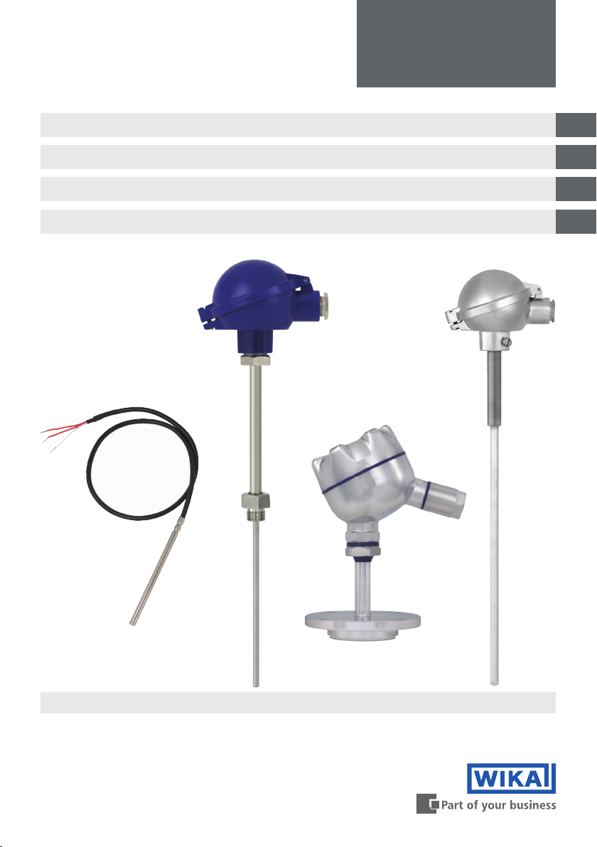
Resistance thermometers and thermocouples
Widerstandsthermometer und Thermoelemente
Sondes à résistance et thermocouples
Termorresistencias y termopares
GB
D
F
E
Examples/Beispiele/Exemples/Ejemplos
Page 2

Operating Instructions models TR and TC
GB
D
Betriebsanleitung Typen TR und TC
F
Mode d'emploi types TR et TC
E
Manual de Instrucciones modelos TR y TC
Page 3 - 18
Seite 19 - 34
Page 35 - 50
Página 51 - 66
© 2010 WIKA Alexander Wiegand SE & Co. KG
All rights reserved. / Alle Rechte vorbehalten.
WIKA® is a registered trademark in various countries.
WIKA® ist eine geschützte Marke in verschiedenen Ländern.
Prior to starting any work, read the operating instructions!
Keep for later use!
Vor Beginn aller Arbeiten Betriebsanleitung lesen!
Zum späteren Gebrauch aufbewahren!
Lire le mode d'emploi avant de commencer toute opération !
A conserver pour une utilisation ultérieure !
¡Leer el manual de instrucciones antes de comenzar cualquier trabajo!
¡Guardar el manual para una eventual consulta!
2
WIKA operating instructions resistance thermometers, thermocouples
11208287.06 10/2013 GB/D/F/E
Page 3
Contents
Contents
1. General information 4
2. Safety 5
3. Specications 8
4. Design and function 10
5. Transport, packaging and storage 11
6. Commissioning, operation 11
GB
Maintenance and cleaning
7.
8. Faults 17
9. Dismounting, return and disposal 18
16
11208287.06 10/2013 GB/D/F/E
WIKA operating instructions resistance thermometers, thermocouples
3
Page 4
1. General information
1. General Information
■
The instrument described in the operating instructions has been manufactured using state-ofthe-art technology. All components are subject to stringent quality and environmental criteria
GB
during production. Our management systems are certied to ISO 9001 and ISO 14001.
■
These operating instructions contain important information on handling the instrument. Working
safely requires that all safety instructions and work instructions are observed.
■
Observe the relevant local accident prevention regulations and general safety regulations for
the instrument's range of use.
■
The operating instructions are part of the instrument and must be kept in the immediate vicinity
of the instrument and readily accessible to skilled personnel at any time.
■
Skilled personnel must have carefully read and understood the operating instructions, prior to
beginning any work.
■
The manufacturer's liability is void in the case of any damage caused by using the product
contrary to its intended use, non-compliance with these operating instructions, assignment of
insuciently qualied skilled personnel or unauthorised modications to the instrument.
■
The general terms and conditions, contained in the sales documentation, shall apply.
■
Subject to technical modications.
■
Further information:
- Internet address:
- Application consultant:
www.wika.de / www.wika.com
Tel.: +49 9372 132-0
Fax: +49 9372 132-406
info@wika.de
Explanation of symbols
WARNING!
... indicates a potentially dangerous situation, which can result in serious injury or
death, if not avoided.
CAUTION!
... indicates a potentially dangerous situation, which can result in light injuries or
damage to equipment or the environment, if not avoided.
Information
... points out useful tips, recommendations and information for ecient and trouble-
free operation.
DANGER!
...identies hazards caused by electric power. Should the safety instructions not be
observed, there is a risk of serious or fatal injury.
4
11208287.06 10/2013 GB/D/F/E
WIKA operating instructions resistance thermometers, thermocouples
Page 5
2. Safety
2. Safety
WARNING!
Before installation, commissioning and operation, ensure that the appropriate
thermometer has been selected in terms of measuring range, design and specic
measuring conditions.
Choose the thermowell with regard to the maximum pressure and temperature (e.g.
table of contact ratings in DIN 43772).
Non-observance can result in serious injury and/or damage to equipment.
Further important safety instructions can be found in the individual chapters of these
operating instructions.
2.1 Intended use
These resistance thermometers and thermocouples are used for temperature measurement in
industrial applications.
The instrument has been designed and built solely for the intended use described here, and may
only be used accordingly.
The technical specications contained in these operating instructions must be observed. Improper
handling or operation of the instrument outside of its technical specications requires the
instrument to be shut down immediately and inspected by an authorised WIKA service engineer.
GB
If the instrument is transported from a cold into a warm environment, the formation of
condensation may result in the instrument malfunctioning. Before putting it back into operation,
wait for the instrument temperature and the room temperature to equalise.
The manufacturer shall not be liable for claims of any type based on operation contrary to the
intended use.
2.2 Personnel qualication
WARNING!
Risk of injury should qualication be insucient!
Improper handling can result in considerable injury and damage to equipment.
■
The activities described in these operating instructions may only be carried out by
skilled personnel who have the qualications described below.
■
Keep unqualied personnel away from hazardous areas.
Skilled personnel
Skilled personnel are understood to be personnel who, based on their technical training,
knowledge of measurement and control technology and on their experience and knowledge of
country-specic regulations, current standards and directives, are capable of carrying out the
work described and independently recognising potential hazards.
Special operating conditions require further appropriate knowledge, e.g. of aggressive media.
11208287.06 10/2013 GB/D/F/E
WIKA operating instructions resistance thermometers, thermocouples
5
Page 6
2. Safety
2.3 Special hazards
GB
WARNING!
For hazardous media such as oxygen, acetylene, ammable or toxic gases or liquids,
and refrigeration plants, compressors, etc., in addition to all standard regulations, the
appropriate existing codes or regulations must also be followed.
WARNING!
Protection from electrostatic discharge (ESD) required. The proper use of grounded
work surfaces and personal wrist straps is required when working with exposed
circuitry (printed circuit boards), in order to to prevent static discharge from damaging
sensitive electronic components.
To ensure safe working on the instrument, the operating company must ensure
■
that suitable rst-aid equipment is available and aid is provided whenever required.
■
that the operating personnel are regularly instructed in all topics regarding work
safety, rst aid and environmental protection and knows the operating instructions
and, in particular, the safety instructions contained therein.
DANGER!
Danger of death caused by electric current
Upon contact with live parts, there is a direct danger of death.
■
Electrical instruments may only be installed and mounted by skilled electrical
personnel.
■
Operation using a defective power supply unit (e.g. short circuit from the mains
voltage to the output voltage) may result in life-threatening voltages at the
instrument!
WARNING!
Residual media in dismounted instruments can result in a risk to persons, the environ-
ment and equipment. Take sucient precautionary measures.
Do not use this instrument in safety or Emergency Stop devices. Incorrect use of the
instrument can result in injury.
Should a failure occur, aggressive media with extremely high temperature and under
high pressure or vacuum may be present at the instrument.
11208287.06 10/2013 GB/D/F/E
6
WIKA operating instructions resistance thermometers, thermocouples
Page 7
2. Safety
2.4 Labelling, safety marks
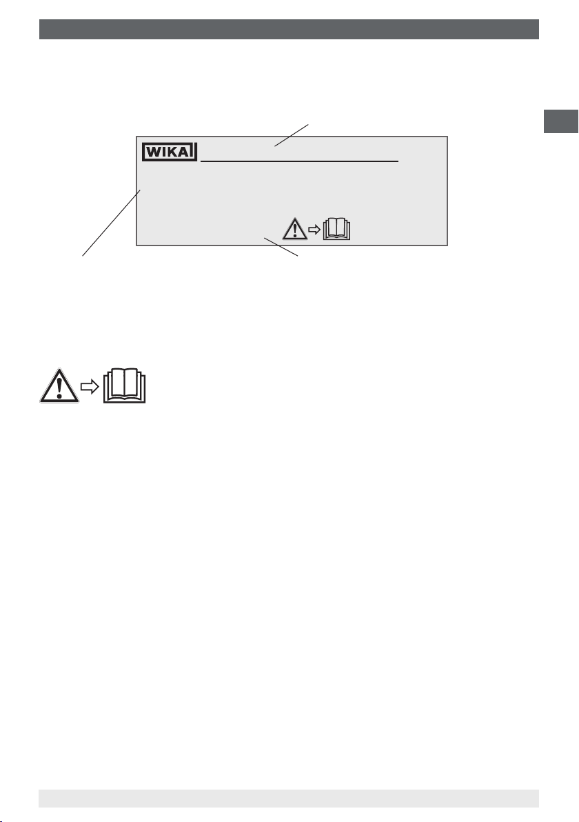
Product labels for resistance thermometers (example)
1 x Pt100 / A / 3 (F) -50 ... +250 °C
Made in Germany 2013
Sensor in accordance with standard
■
F Thin-lm resistor
■
W Wire-wound resistor
Explanation of symbols
Before mounting and commissioning the instrument, make sure you read
the operating instructions!
TR10-B
Model
11012345
EN 60751
Year of manufacture
GB
11208287.06 10/2013 GB/D/F/E
WIKA operating instructions resistance thermometers, thermocouples
7
Page 8

3. Specications
3. Specications
3.1 Resistance thermometer
GB
Sensor connection method
■
2-wire
■
3-wire
■
4-wire
Sensor tolerance value per DIN EN 60751
■
Class B
■
Class A
■
Class AA
The combinations of a 2-wire connection with class A or class AA are not permissible, since the
lead resistance of the measuring insert negates the higher sensor accuracy.
Basic values and tolerance values
Basic values and tolerance values for the platinum measurement resistances are laid down in
DIN EN 60751.
The nominal value of Pt100 sensors is 100 Ω at 0 °C. The temperature coecient α can be stated
simply to be between 0 °C and 100 °C with:
-3
-1
α = 3.85 ∙ 10
The relationship between temperature and electrical resistance is described by polynomials,
which are also dened in DIN EN 60751. Moreover, this standard species the basic values in
°C steps in tabular form. Moreover, this standard species the basic values in °C steps in tabular
form.
Class
B -196 … +600 °C -50 … +500 °C ±(0.30 + 0.0050 | t |)
A -100 … +450 °C -30 … +300 °C ±(0.15 + 0.0020 | t |)
AA -50 … +250 °C 0 … 150 °C ±(0.10 + 0.0017 | t |)
Temperature range
Wire-wound (W) Thin-lm (F)
°C
Tolerance value in °C
1)
1)
1)
1) | t | is the value of the temperature in °C without consideration of the sign.
Bold: Standard version
For further technical information, see WIKA data sheet and the technical information sheet
IN 00.17 “Usage limitations and accuracies of platinum resistance thermometers per
EN 60751: 2008”.
8
WIKA operating instructions resistance thermometers, thermocouples
11208287.06 10/2013 GB/D/F/E
Page 9

3. Specications
3.2 Thermocouples
3.2.1 Sensor types
Model
K 1,200 °C
J 800 °C
E 800 °C
N 1,200 °C
3.2.2 Potential measurement uncertainties
Important factors which counteract the long-term stability of thermocouples.
Ageing eects/poisoning
■
Oxidation processes in thermocouples which are not appropriately protected (“bare”
thermocouple wires) result in falsications of the characteristic curves.
■
Foreign atoms (poisoning) that diuse into the original alloys lead to changes of these original
alloys and thus falsify the characteristic curve.
■
The inuence of hydrogen leads to the embrittlement of the thermocouples.
The Ni leg of the type K thermocouple is often damaged by sulphur which is contained in exhaust
gases, for example. Thermocouple types J and T age slightly, as the pure metal leg oxidises rst.
In general, rising temperatures cause accelerated ageing eects.
Green rot
If type K thermocouples are used at temperatures from approx. 800 °C to 1,050 °C, considerable
changes of the thermoelectric voltage can occur. The cause of this is a chromium depletion or
the chrome oxidation in the NiCr leg (+ leg). The precondition for this is a low concentration of
oxygen or steam in the immediate environment of the thermocouple. The nickel leg is not aected
by it. The consequence of this eect is a drift of the measured value caused by decreasing
thermoelectric voltage. This eect is accelerated if there is a shortage of oxygen (reducing
atmosphere), since a complete oxide layer, which would protect it from further oxidation of the
chromium, cannot be formed on the surface of the thermocouple.
Recommended max. operating temperature
GB
The thermocouple is permanently destroyed by this process. The name green rot is derived from
the greenish shimmering colouration on the breaking point of the wire.
The thermocouple type N has in this regard an advantage due to its silicium content. Here, a
protective oxide layer forms on its surface under the same conditions.
K eect
The NiCr leg of a type K thermocouple has an ordered alignment with respect to the alignment
in the crystal lattice below approx. 400 °C. If the thermocouple is heated further, a transition to
a disordered state occurs in the temperature range between approx. 400 °C and 600 °C. Above
600 °C, an ordered crystal lattice is restored.
11208287.06 10/2013 GB/D/F/E
WIKA operating instructions resistance thermometers, thermocouples
9
Page 10

3. Specications / 4. Design and function
If these thermocouples cool too quickly (quicker than approx. 100 °C per hour), the undesirable
disordered crystal lattice occurs again during cooling in the range from approx. 600 °C to
approx. 400 °C. In the characteristic curve of type K, however, a consistently ordered alignment
state is assumed and provided with values. This results in a fault of thermoelectric voltage of up
GB
to approx. 0.8 mV (approx. 5 °C) in this range. The K eect is reversible and is largely eliminated
again by annealing above 700 °C, followed by correspondingly slow cooling.
Thin sheathed thermocouples are particularly sensitive in this respect. Cooling in resting air can
already lead to deviations of 1 K.
In type N thermocouple, it has been possible to reduce this short-range-order eect by alloying
both legs with silicium.
The application range of these thermometers is limited both by the permissible maximum
temperature of the thermocouple and by the max. temperature of the thermowell material.
Listed models are available both as single or dual thermocouples. The thermocouple will be
delivered with an insulated measuring point, unless explicitly specied otherwise.
Tolerance value
For the tolerance value of thermocouples, a cold junction temperature of 0 °C has been taken as
the basis. When using a compensating cable or thermocouple cable, an additional measuring
error must be considered.
For limiting deviations and further specications, see the corresponding WIKA data sheet and
technical information sheet IN 00.23, “Application of thermocouples”.
4. Design and function
4.1 Description
These thermometers (resistance thermometers and thermocouples) detect temperatures in
processes. These thermometers are suitable, depending on the version, for low, medium and high
process requirements.
They can be assembled as cable probes or as thermometers with a connection head. Optionally,
a temperature transmitter can be built into the connection head. For this temperature transmitter,
separate operating instructions will be enclosed.
Certain thermometer versions can be combined with a large number of thermowell designs.
Operation of these thermometers without a thermowell is only appropriate in special cases.
4.2 Scope of delivery
Cross-check scope of delivery with delivery note.
10
WIKA operating instructions resistance thermometers, thermocouples
11208287.06 10/2013 GB/D/F/E
Page 11
5. Transport, packaging and storage / 6. Commissioning, operation
5. Transport, packaging and storage
5.1 Transport
Check instrument for any damage that may have been caused by transport. Obvious damage
must be reported immediately.
5.2 Packaging
Do not remove packaging until just before mounting.
Keep the packaging as it will provide optimum protection during transport (e.g. change in
installation site, sending for repair).
5.3 Storage
Permissible conditions at the place of storage:
■
Storage temperature:
Instruments without built-in transmitter: -40 ... +85 °C
Instruments with built-in transmitter: see operating instructions of the corresponding
■
Humidity: 35 ... 85 % relative humidity (no condensation)
Avoid exposure to the following factors:
■
Direct sunlight or proximity to hot objects
■
Mechanical vibration, mechanical shock (putting it down hard)
■
Soot, vapour, dust and corrosive gases
■
Potentially explosive environments, ammable atmospheres
transmitter
GB
Store the instrument in its original packaging in a location that fullls the conditions listed above. If
the original packaging is not available, pack and store the instrument as described below:
1. Wrap the instrument in an antistatic plastic lm.
2. Place the instrument, along with shock-absorbent material, in the packaging.
3. If stored for a prolonged period of time (more than 30 days), place a bag, containing a
desiccant, inside the packaging.
WARNING!
Before storing the instrument (following operation), remove any residual media. This
is of particular importance if the medium is hazardous to health, e.g. caustic, toxic,
carcinogenic, radioactive, etc.
6. Commissioning, operation
WARNING!
When the thermometer is mounted, the temperature must not drop below the allowed
operating temperature (environment, medium) or exceed it, even when taking
convection and heat radiation into account!
WARNING!
Thermometers must be earthed if dangerous voltages could be expected at the
connection wires (caused, for example, by mechanical damage, electrostatic
11208287.06 10/2013 GB/D/F/E
WIKA operating instructions resistance thermometers, thermocouples
discharge or induction)!
11
Page 12
6. Commissioning, operation
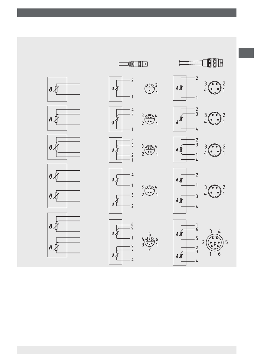
6.1 Electrical connection
CAUTION!
■
Damage to cables and wires, and to connection points must be avoided
GB
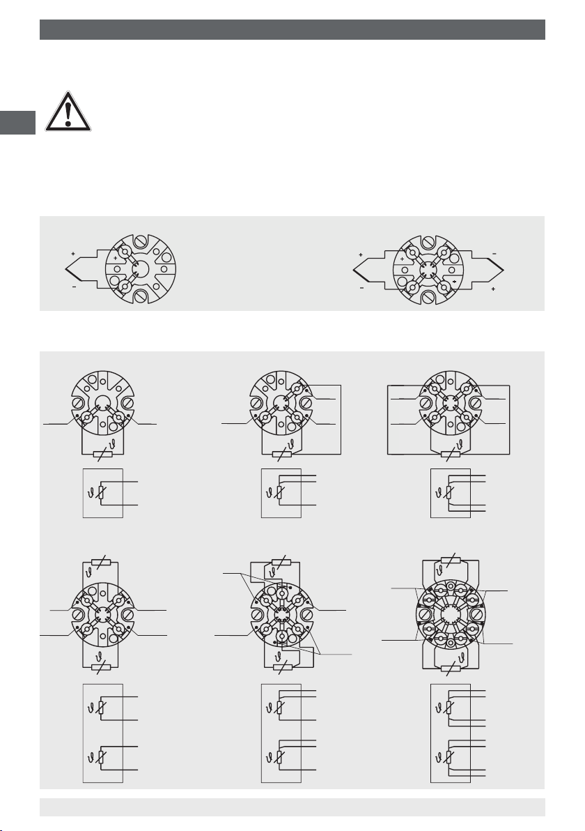
The electrical connection is to be made according to the sensor connections/pin assignments
shown below:
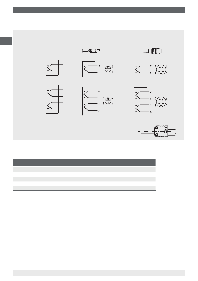
Thermocouples with terminal block
Resistance thermometers with terminal block
1 x Pt100, 2-wire 1 x Pt100, 3-wire 1 x Pt100, 4-wire
■
Flying leads with bare ends must be nished with ferrule ends (cable preparation)
■
Both the internal capacitance and inductance must be considered
Single thermocouple
The colour coding at the
positive connection to the
devices always decides the
correlation of polarity and
connection terminal.
Dual thermocouple
white
red
red
white
white
2 x Pt100, 2-wire 2 x Pt100, 3-wire
red
red
yellow
12
white
black
red
white
black
yellow
yellow
WIKA operating instructions resistance thermometers, thermocouples
red
red
red
red
white
white
black
red
red
white
black
black
yellow
white
white
2 x Pt100, 4-wire
white
yellow
red
red
red
red
white
white
red
black
red
red
white
white
black
black
yellow
yellow
3160629.06
11208287.06 10/2013 GB/D/F/E
Page 13
6. Commissioning, operation
Resistance thermometers with cable connection or male connector
1 x Pt100
2-wire
1 x Pt100
3-wire
1 x Pt100
4-wire
2 x Pt100
2-wire
2 x Pt100
3-wire
Cable
red
white
red
red
white
red
red
white
white
red
white
black
yellow
red
red
white
black
black
Lemosa connector,
(male) on cable
Binder male connector,
tted to cable
GB
yellow
11208287.06 10/2013 GB/D/F/E
WIKA operating instructions resistance thermometers, thermocouples
13
Page 14
6. Commissioning, operation
Thermocouples with cable connection or male connector
GB
Single
thermocouple
Dual
thermocouple
Thermo connector
Cable
Colour coding of
the wire ends see
table
Positive and negative terminal are marked. Two
miniature size thermo connectors are used with
dual thermocouples.
Lemosa connector,
(male) on cable
Binder connector,
(male) on cable
(threaded plug connection)
Colour code of cable
Type of sensor Standard Positive terminal Negative terminal
K DIN EN 60584 green white
J DIN EN 60584 black white
E DIN EN 60584 violet white
T DIN EN 60584 brown white
N DIN EN 60584 pink white
14
11208287.06 10/2013 GB/D/F/E
WIKA operating instructions resistance thermometers, thermocouples
Page 15
6. Commissioning, operation
6.2 Cable connections
The cable gland must be optimally sealed, to ensure that the required protection class is reached.
Requirements for meeting ingress protection
■
Only use cable glands within their indicated clamping range (cable diameter suitable for the
cable gland)
■
Do not use the lower clamping area with very soft cable types
■
Only use circular cross-section cables (if necessary, slightly oval in cross-section)
■
Do not twist the cable
■
Repeated opening/closing is possible; however only if necessary, as it might have a detrimental
eect on the protection class
■
For cable with a pronounced cold-ow behaviour the screw connection must be fully tightened
CAUTION!
■
The protection class is not valid with armoured cables (stainless steel sheathed)
■
Seal should be checked for signs of brittleness and, if necessary, replaced
6.3 Parallel threads
If the thermometer connecting head, extension neck, thermowell or process connection are
connected to parallel threads (e.g. G ½, M20 x 1.5 ...), these threads must be secured using seals
which prevent liquids from penetrating into the thermometer.
As standard, WIKA uses copper prole seals for the connection between the neck tube and the
thermowell, and at paper seals for the connection of the connection head and the extension neck
or thermowell.
If the thermometer and the thermowell are already connected, the seals will already be mounted.
The plant operator must check whether the seals are suitable for the operating conditions and
must replace them, if necessary, with suitable seals.
For thermometers without a thermowell, and/or where these are delivered separately, the seals
are not included and must be ordered separately.
GB
Tighten the threads by hand when carrying out the nal assembly on the plant. This will
correspond to the delivery status of the premounted components. The nal tightening torque
should be applied using a spanner (half rotation).
The seals must be replaced after dismantling!
The seals can be ordered from WIKA, indicating the WIKA order number and/or the
designation (see table).
11208287.06 10/2013 GB/D/F/E
WIKA operating instructions resistance thermometers, thermocouples
15
Page 16
6. Commissioning, operation / 7. Maintenance and cleaning
WIKA order no.
11349981 per DIN 7603 Form C 14 x 18 x 2 -CuFA G ¼, M14 x 1,5
11349990 per DIN 7603 Form C 18 x 22 x 2 -CuFA M18 x 1,5, G ⅜
GB
11350008 per DIN 7603 Form C 21 x 26 x 2 -CuFA G ½, M20 x 1,5
11350016 per DIN 7603 Form C 27 x 32 x 2.5 -CuFA G ¾, M27 x 2
11367416 per DIN 7603 Form C20 x 24 x 2 -CuFA M20 x 1,5
1248278 per DIN 7603 D21.2 x D25.9 x 1.5 -Al G ½, M20 x 1,5
3153134
3361485
Legend:
CuFA = Copper, max. 45 HB
Al = Aluminium Al99
F11, 32 to 45 HB
StFA = Soft iron, 80 to 95 HBa, with a lling made of asbestos-free sealing material
Designation Suitable for threads
per DIN 7603 Form C D14.2 x D17.9 x 2 -StFA
per DIN 7603 Form C D33.3 x D38.9 x 2.5 -
a
, with a lling made of asbestos-free sealing material
b
StFA
G ¼, M14 x 1,5
G 1
6.4 Tapered threads (NPT)
Connections with tapered threads (NPT) are self-sealing and normally must not be sealed. It
should be checked whether it may be necessary to seal them additionally with PTFE tape or
hemp. The threads must be lubricated with a suitable lubricant before tting.
Tighten the threads by hand when carrying out the nal assembly on the plant. This will
correspond to the delivery status of the premounted components. The nal tightening and sealing
must be made with a spanner (1.5 to 3 rotations).
7. Maintenance and cleaning
7.1 Maintenance
These thermometers are maintenance-free.
Repairs must only be carried out by the manufacturer.
7.2 Cleaning
CAUTION!
■
Before cleaning, correctly disconnect the instrument from the pressure supply,
switch it o and disconnect it from the mains.
■
Clean the instrument with a moist cloth.
■
Electrical connections must not come into contact with moisture.
■
Wash or clean the dismounted instrument before returning it, in order to protect
personnel and the environment from exposure to residual media.
■
Residual media in dismounted instruments can result in a risk to personnel, the
environment and equipment. Take sucient precautionary measures.
For information on returning the instrument see chapter 9.2 “Return”.
16
WIKA operating instructions resistance thermometers, thermocouples
11208287.06 10/2013 GB/D/F/E
Page 17
8. Faults
7.3 Calibration, Recalibration
It is recommended that the measuring insert is recalibrated at regular intervals (resistance
thermometers: approx. 24 months, thermocouples: approx. 12 months). This period can be
reduced, depending on the particular application. The calibration can be carried out by the
manufacturer, as well as on site by qualied technical sta with calibration instruments.
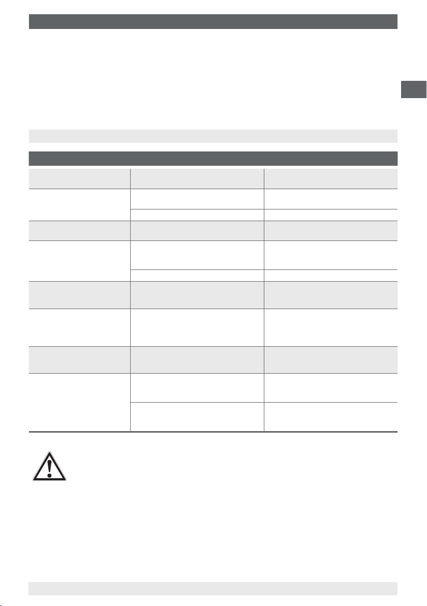
8. Faults
Faults Causes Measures
No signal/line breakage
Erroneous measured values
Erroneous measured values
(too low)
Erroneous measured values
and response times too long
Erroneous measured values
(of thermocouples)
Indication of the measured
value jumps
Corrosion
Signal interference
Mechanical load too high or
overtemperature
Sensor drift caused by
overtemperature
Sensor drift caused by chemical attack
Entry of moisture into cable or
measuring insert
Wrong mounting geometry, for example
mounting depth too deep or heat
dissipation too high
Deposits on the sensor or thermowell Remove deposits
Parasitic voltages (thermal voltages,
galvanic voltage) or wrong equalisation
line
Cable break in connecting cable or
loose contact caused by mechanical
overload
Composition of the medium not
as expected or modied or wrong
thermowell material selected
Stray currents caused by electric elds
or earth loops
Earth circuits Elimination of potentials, use of
Replace probe or measuring insert
with a suitable design
Replace probe or measuring insert
with a suitable design
Use a design with thermowell
Replace probe or measuring insert
with a suitable design
The temperature-sensitive area of the
sensor must be inside the medium,
and surfaces must be isolated.
Use a suitable equalisation line
Replace probe or measuring insert
with a suitable design, for example
equipped with a strain relief or a
thicker conductor cross-section
Analyse medium and then select a
more-suitable material or replace
thermowell regularly
Use of screened connecting cables,
increase in the distance to motors and
power lines
galvanically isolated transmitter supply
isolators or transmitters
GB
CAUTION!
If deciencies cannot be eliminated by means of the measures listed above, shut
down the instrument immediately, and ensure that pressure and/or signal are no
longer present, and secure the instrument from being put back into operation
inadvertently.
In this case, contact the manufacturer.
If a return is needed, please follow the instructions see chapter 9.2 “Return”.
11208287.06 10/2013 GB/D/F/E
WIKA operating instructions resistance thermometers, thermocouples
17
Page 18
9. Dismounting, return and disposal
9. Dismounting, return and disposal
WARNING!
GB
9.1 Dismounting
Only disconnect the thermometer once the system has been depressurised!
9.2 Return
When returning the instrument, use the original packaging or a suitable transport package.
To avoid damage:
1. Wrap the instrument in an antistatic plastic lm.
2. Place the instrument, along with the shock-absorbing material, in the packaging.
Place shock-absorbing material evenly on all sides of the shipping packaging.
3. If possible, place a bag, containing a desiccant, inside the packaging.
4. Label the shipment as transport of a highly sensitive measuring instrument.
Residual media in dismounted instruments can result in a risk to persons, the
environment and equipment. Take sucient precautionary measures.
WARNING!
Risk of burns!
Let the instrument cool down suciently before dismounting it! When dismounting it,
there is a risk that dangerously hot pressure media may escape.
WARNING!
Strictly observe when shipping the instrument:
All instruments delivered to WIKA must be free from any kind of hazardous substances
(acids, leachate, solutions, etc.).
Information on returns can be found under the heading “Service” on our local website.
9.3 Disposal
Incorrect disposal may endanger the environment.
Dispose of instrument components and packaging materials in an environmentally compatible
way and in accordance with the country-specic waste disposal regulations.
18
WIKA operating instructions resistance thermometers, thermocouples
11208287.06 10/2013 GB/D/F/E
Page 19
Inhalt
Inhalt
1. Allgemeines 20
2. Sicherheit 21
3. Technische Daten 24
4. Aufbau und Funktion 26
5. Transport, Verpackung und Lagerung 27
6. Inbetriebnahme, Betrieb 27
Wartung und Reinigung
7.
8. Störungen 33
9. Demontage, Rücksendung und Entsorgung 34
32
D
11208287.06 10/2013 GB/D/F/E
WIKA Betriebsanleitung Widerstandsthermometer, Thermoelemente
19
Page 20
1. Allgemeines
1. Allgemeines
■
Das in der Betriebsanleitung beschriebene Gerät wird nach dem aktuellen Stand der Technik
gefertigt. Alle Komponenten unterliegen während der Fertigung strengen Qualitäts- und
Umweltkriterien. Unsere Managementsysteme sind nach ISO 9001 und ISO 14001 zertiziert.
■
Diese Betriebsanleitung gibt wichtige Hinweise zum Umgang mit dem Gerät. Voraussetzung
D
für sicheres Arbeiten ist die Einhaltung aller angegebenen Sicherheitshinweise und
Handlungsanweisungen.
■
Die für den Einsatzbereich des Gerätes geltenden örtlichen Unfallverhütungsvorschriften und
allgemeinen Sicherheitsbestimmungen einhalten.
■
Die Betriebsanleitung ist Produktbestandteil und muss in unmittelbarer Nähe des Gerätes für
das Fachpersonal jederzeit zugänglich aufbewahrt werden.
■
Das Fachpersonal muss die Betriebsanleitung vor Beginn aller Arbeiten sorgfältig durchgelesen und verstanden haben.
■
Die Haftung des Herstellers erlischt bei Schäden durch bestimmungswidrige Verwendung,
Nichtbeachten dieser Betriebsanleitung, Einsatz ungenügend qualizierten Fachpersonals
sowie eigenmächtiger Veränderung am Gerät.
■
Es gelten die allgemeinen Geschäftsbedingungen in den Verkaufsunterlagen.
■
Technische Änderungen vorbehalten.
■
Weitere Informationen:
- Internet-Adresse: www.wika.de / www.wika.com
- Anwendungsberater:
Tel.: +49 9372 132-0
Fax: +49 9372 132-406
info@wika.de
Symbolerklärung
WARNUNG!
… weist auf eine möglicherweise gefährliche Situation hin, die zum Tod oder zu
schweren Verletzungen führen kann, wenn sie nicht gemieden wird.
VORSICHT!
… weist auf eine möglicherweise gefährliche Situation hin, die zu geringfügigen oder
leichten Verletzungen bzw. Sach- und Umweltschäden führen kann, wenn sie nicht
gemieden wird.
Information
… hebt nützliche Tipps und Empfehlungen sowie Informationen für einen ezienten
und störungsfreien Betrieb hervor.
GEFAHR!
… kennzeichnet Gefährdungen durch elektrischen Strom. Bei Nichtbeachtung der
Sicherheitshinweise besteht die Gefahr schwerer oder tödlicher Verletzungen.
20
11208287.06 10/2013 GB/D/F/E
WIKA Betriebsanleitung Widerstandsthermometer, Thermoelemente
Page 21
2. Sicherheit
2. Sicherheit
WARNUNG!
Vor Montage, Inbetriebnahme und Betrieb sicherstellen, dass das richtige Thermo-
meter hinsichtlich Messbereich, Ausführung und spezischen Messbedingungen
ausgewählt wurde.
Schutzrohr hinsichtlich Maximaldruck und -temperatur (z. B. Belastungsdiagramme in
DIN 43772) auswählen.
Bei Nichtbeachten können schwere Körperverletzungen und/oder Sachschäden
auftreten.
Weitere wichtige Sicherheitshinweise benden sich in den einzelnen Kapiteln dieser
Betriebsanleitung.
2.1 Bestimmungsgemäße Verwendung
Diese Widerstandsthermometer und Thermoelemente dienen zur Temperaturmessung in industriellen Anwendungen.
Das Gerät ist ausschließlich für den hier beschriebenen bestimmungsgemäßen Verwendungszweck konzipiert und konstruiert und darf nur dementsprechend verwendet werden.
Die technischen Spezikationen in dieser Betriebsanleitung sind einzuhalten. Eine unsachgemäße Handhabung oder ein Betreiben des Gerätes außerhalb der technischen Spezikationen
macht die sofortige Stilllegung und Überprüfung durch einen autorisierten WIKA-Servicemitarbeiter erforderlich.
D
Wird das Gerät von einer kalten in eine warme Umgebung transportiert, so kann durch Kondensatbildung eine Störung der Gerätefunktion eintreten. Vor einer erneuten Inbetriebnahme die
Angleichung der Gerätetemperatur an die Raumtemperatur abwarten.
Ansprüche jeglicher Art aufgrund von nicht bestimmungsgemäßer Verwendung sind ausgeschlossen.
2.2 Personalqualikation
WARNUNG!
Verletzungsgefahr bei unzureichender Qualikation!
Unsachgemäßer Umgang kann zu erheblichen Personen- und Sachschäden führen.
■
Die in dieser Betriebsanleitung beschriebenen Tätigkeiten nur durch Fachpersonal
nachfolgend beschriebener Qualikation durchführen lassen.
■
Unqualiziertes Personal von den Gefahrenbereichen fernhalten.
Fachpersonal
Das Fachpersonal ist aufgrund seiner fachlichen Ausbildung, seiner Kenntnisse der Mess- und
Regelungstechnik und seiner Erfahrungen sowie Kenntnis der landesspezischen Vorschriften,
geltenden Normen und Richtlinien in der Lage, die beschriebenen Arbeiten auszuführen und
mögliche Gefahren selbstständig zu erkennen.
Spezielle Einsatzbedingungen verlangen weiteres entsprechendes Wissen, z. B. über agressive
Medien.
11208287.06 10/2013 GB/D/F/E
WIKA Betriebsanleitung Widerstandsthermometer, Thermoelemente
21
Page 22

2. Sicherheit
2.3 Besondere Gefahren
WARNUNG!
Bei gefährlichen Messstoen wie z. B. Sauersto, Acetylen, brennbaren oder giftigen
Stoen, sowie bei Kälteanlagen, Kompressoren etc. müssen über die gesamten allge-
D
meinen Regeln hinaus die einschlägigen Vorschriften beachtet werden.
WARNUNG!
Schutz vor elektrostatischer Entladung (ESD) erforderlich! Die ordnungsgemäße
Verwendung geerdeter Arbeitsächen und persönlicher Armbänder ist bei Arbeiten
mit oenen Schaltkreisen (Leiterplatten) erforderlich, um die Beschädigung empnd-
licher elektronischer Bauteile durch elektrostatische Entladung zu vermeiden.
Für ein sicheres Arbeiten am Gerät muss der Betreiber sicherstellen,
■
dass eine entsprechende Erste-Hilfe-Ausrüstung vorhanden ist und bei Bedarf
jederzeit Hilfe zur Stelle ist.
■
dass das Bedienpersonal regelmäßig in allen zutreenden Fragen von Arbeits-
sicherheit, Erste-Hilfe und Umweltschutz unterwiesen wird, sowie die Betriebsanleitung und insbesondere die darin enthaltenen Sicherheitshinweise kennt.
GEFAHR!
Lebensgefahr durch elektrischen Strom
Bei Berührung mit spannungsführenden Teilen besteht unmittelbare Lebensgefahr.
■
Einbau und Montage des elektrischen Gerätes dürfen nur durch das Elektrofachpersonal erfolgen.
■
Bei Betrieb mit einem defekten Netzgerät (z. B. Kurzschluss von Netzspannung zur
Ausgangsspannung) können am Gerät lebensgefährliche Spannungen auftreten!
22
WARNUNG!
Messstoreste in ausgebauten Geräten können zur Gefährdung von Personen,
Umwelt und Einrichtung führen. Ausreichende Vorsichtsmaßnahmen ergreifen.
Dieses Gerät nicht in Sicherheits- oder in Not-Aus-Einrichtungen benutzen. Fehlerhafte Anwendungen des Gerätes können zu Verletzungen führen.
Am Gerät können im Fehlerfall aggressive Medien mit extremer Temperatur und unter
hohem Druck oder Vakuum anliegen.
11208287.06 10/2013 GB/D/F/E
WIKA Betriebsanleitung Widerstandsthermometer, Thermoelemente
Page 23

2. Sicherheit
2.4 Beschilderung, Sicherheitskennzeichnungen
Typenschild für Widerstandsthermometer (Beispiel)
Typ
Sensor gemäß Norm
■
F Dünnlm-Messwiderstand
■
W Drahtgewickelter Messwiderstand
Symbolerklärung
TR10-B
11012345
EN 60751
1 x Pt100 / A / 3 (F) -50 ... +250 °C
Made in Germany 2013
Herstellungsjahr
Vor Montage und Inbetriebnahme des Gerätes unbedingt die Betriebsanleitung lesen!
D
11208287.06 10/2013 GB/D/F/E
WIKA Betriebsanleitung Widerstandsthermometer, Thermoelemente
23
Page 24

3. Technische Daten
3. Technische Daten
3.1 Widerstandsthermometer
Sensor-Schaltungsart
■
2-Leiter
■
3-Leiter
D
■
4-Leiter
Grenzabweichung des Sensors nach DIN EN 60751
■
Klasse B
■
Klasse A
■
Klasse AA
Die Kombinationen 2-Leiter-Schaltungsart und Klasse A oder Klasse AA sind nicht zulässig, da
der Leitungswiderstand des Messeinsatzes der höheren Sensorgenauigkeit entgegen wirkt.
Grundwerte und Grenzabweichungen
Grundwerte und Grenzabweichungen von Platin-Messwiderständen sind festgelegt in
DIN EN 60751.
Der Nennwert von Pt100 Sensoren beträgt 100 Ω bei 0 °C. Der Temperaturkoezient α kann
zwischen 0 °C und 100 °C vereinfacht angegeben werden mit:
-3
-1
α = 3,85 ∙ 10
Der Zusammenhang zwischen der Temperatur und dem elektrischen Widerstand wird durch
Polynome beschrieben, die ebenfalls in DIN EN 60751 deniert sind. Weiterhin legt diese Norm
die Grundwerte in °C-Schritten tabellarisch fest.
Klasse
B -196 … +600 °C -50 … +500 °C ±(0,30 + 0,0050 | t |)
A -100 … +450 °C -30 … +300 °C ±(0,15 + 0,0020 | t |)
AA -50 … +250 °C 0 … +150 °C ±(0,10 + 0,0017 | t |)
Temperaturbereich
Drahtgewickelt (W) Dünnschicht (F)
°C
Grenzabweichung in °C
1)
1)
1)
1) | t | ist der Zahlenwert der Temperatur in °C ohne Berücksichtigung des Vorzeichens.
Fett gedruckt: Standardausführung
Weitere technische Daten siehe WIKA-Datenblatt und Technische Information IN 00.17 „Einsatzgrenzen und Genauigkeiten von Platin-Widerstandsthermometern nach EN 60751: 2008“.
24
WIKA Betriebsanleitung Widerstandsthermometer, Thermoelemente
11208287.06 10/2013 GB/D/F/E
Page 25

3. Technische Daten
3.2 Thermoelemente
3.2.1 Sensortypen
Typ
K 1.200 °C
J 800 °C
E 800 °C
N 1.200 °C
3.2.2 Potenzielle Messunsicherheiten
Wichtige Faktoren, die der Langzeitstabilität von Thermoelementen entgegenwirken.
Alterungserscheinungen/Vergiftungen
■
Oxidationsvorgänge führen bei nicht entsprechend geschützten Thermoelementen („blanke“
Thermodrähte) zu Kennlinienverfälschungen.
■
Eindiundierende Fremdatome (Vergiftungen) führen zu Veränderungen der Ursprungslegierungen und damit zu Verfälschungen der Kennlinie.
■
Der Einuss von Wassersto führt zur Versprödung der Thermoelemente.
Der Ni-Schenkel des Typ K-Thermoelementes wird häug durch Schwefel, der z. B. in Rauchga-
sen vorkommt, geschädigt. Thermoelemente der Typen J und T altern gering, weil zunächst der
Reinmetallschenkel oxydiert.
Generell nehmen die Alterungserscheinungen mit steigenden Temperaturen zu.
Empfohlene max. Betriebstemperatur
D
Grünfäule
Bei Typ K-Thermoelementen können beim Einsatz in Temperaturen von ca. 800 °C bis 1.050 °C
erhebliche Veränderungen der Thermospannung auftreten. Die Ursache hierfür ist eine Chromverarmung bzw. Oxidation des Chroms im NiCr-Schenkel (+ Schenkel). Voraussetzung hierfür
ist eine geringe Konzentration Sauersto oder Wasserdampf in der direkten Umgebung des
Thermoelementes. Der Nickel-Schenkel ist hiervon nicht betroen. Die Folge dieses Eekts ist
eine Drift des Messwertes durch sinkende Thermospannung. Bei Sauerstomangel (reduzierende
Atmosphäre) wird dieser Eekt noch beschleunigt, da sich keine vollständigen Oxidhäute auf der
Oberäche des Thermoelementes ausbilden können, die einer weiteren Oxidation des Chroms
entgegenwirken.
Das Thermoelement wird auf Dauer durch diesen Vorgang zerstört. Der Name Grünfäule kommt
von der grünlichen schimmernden Färbung an der Bruchstelle des Drahtes.
Das Thermoelement Typ N ist bedingt durch seinen Siliziumgehalt in dieser Beziehung im Vorteil.
Hier bildet sich unter gleichen Bedingungen eine schützende Oxidschicht auf seiner Oberäche
aus.
K-Eekt
Der NiCr-Schenkel eines Typ K-Thermoelementes besitzt bezüglich der Ausrichtung im Kristallgit-
ter unterhalb ca. 400 °C eine geordnete Ausrichtung. Wird das Thermoelement weiter erhitzt, so
ndet im Temperaturbereich zwischen ca. 400 °C und 600 °C ein Übergang in einen ungeordneten Zustand statt. Oberhalb von 600 °C stellt sich wieder ein geordnetes Kristallgitter ein.
11208287.06 10/2013 GB/D/F/E
WIKA Betriebsanleitung Widerstandsthermometer, Thermoelemente
25
Page 26

3. Technische Daten / 4. Aufbau und Funktion
Bei einem zu schnellen Abkühlen dieser Thermoelemente (schneller als ca. 100 °C pro Stunde)
kommt es während der Abkühlung im Bereich von ca. 600 °C bis ca. 400 °C wieder zum
unerwünschten ungeordneten Kristallgitter. In der Kennlinie von Typ K ist aber ein durchgängig
geordneter Ausrichtungszustand vorausgesetzt und mit Werten hinterlegt. Ein Thermospannungs-
fehler von bis zu ca. 0,8 mV (ca. 5 °C) in diesem Bereich ist die Folge. Der K-Eekt ist reversibel
und wird durch Glühen oberhalb 700 °C mit anschließender entsprechend langsamer Abkühlung
D
größtenteils wieder abgebaut.
Dünne Mantel-Thermoelemente reagieren hier besonders empndlich. Schon eine Abkühlung an
ruhender Luft kann Abweichungen von 1 °C zur Folge haben.
Beim Typ N-Thermoelement hat man diesen Nahordnungseekt durch Legieren beider Schenkel
mit Silizium verringern können.
Die tatsächliche Gebrauchstemperatur des Thermometers wird begrenzt sowohl durch die
maximal zulässige Einsatztemperatur des Thermoelementes, als auch durch die maximal zulässi-
ge Einsatztemperatur des Schutzrohrwerkstoes.
Gelistete Typen sind als einfaches Thermopaar oder als doppeltes Thermopaar lieferbar. Das
Thermoelement wird mit isolierter Messstelle geliefert, wenn nicht ausdrücklich anders speziziert
wurde.
Grenzabweichung
Bei der Grenzabweichung von Thermopaaren ist eine Vergleichsstellentemperatur von 0 °C
zugrunde gelegt. Bei Verwendung einer Ausgleichs- oder Thermoleitung muss eine zusätzliche
Messabweichung berücksichtigt werden.
Grenzabweichungen und weitere technische Daten siehe entsprechendes WIKA-Datenblatt und
Technische Information IN 00.23 „Einsatz von Thermoelementen“.
4. Aufbau und Funktion
4.1 Beschreibung
Mit Hilfe dieser Thermometer (Widerstandsthermometer und Thermoelemente) werden Temperaturen in Prozessen erfasst. Diese Thermometer eignen sich je nach Ausführung für niedrige,
mittlere und hohe Prozessanforderungen.
Sie können als Kabelfühler oder als Thermometer mit Anschlusskopf aufgebaut werden. Optional
kann ein Temperatur-Transmitter im Anschlusskopf eingebaut werden. Für diesen TemperaturTransmitter wird eine eigene Betriebsanleitung beigelegt.
Bestimmte Thermometerausführungen können mit einer Vielzahl von Schutzrohrbauformen
kombiniert werden. Ein Betrieb dieser Thermometer ohne Schutzrohr ist nur in speziellen Fällen
zweckmäßig.
4.2 Lieferumfang
Lieferumfang mit dem Lieferschein abgleichen.
26
WIKA Betriebsanleitung Widerstandsthermometer, Thermoelemente
11208287.06 10/2013 GB/D/F/E
Page 27

5. Transport, Verpackung und Lagerung / 6. Inbetriebnahme, Betrieb
5. Transport, Verpackung und Lagerung
5.1 Transport
Gerät auf eventuell vorhandene Transportschäden untersuchen.
Oensichtliche Schäden unverzüglich mitteilen.
5.2 Verpackung
Verpackung erst unmittelbar vor der Montage entfernen.
Die Verpackung aufbewahren, denn diese bietet bei einem Transport einen optimalen Schutz
(z. B. wechselnder Einbauort, Reparatursendung).
5.3 Lagerung
Zulässige Bedingungen am Lagerort:
■
Lagertemperatur:
Geräte ohne eingebauten Transmitter: -40 ... +85 °C
Geräte mit eingebautem Transmitter: siehe Betriebsanleitung des entspr. Transmitters
■
Feuchtigkeit: 35 ... 85 % relative Feuchte (keine Betauung)
Vermeidung folgender Einüsse:
■
Direktes Sonnenlicht oder Nähe zu heißen Gegenständen
■
Mechanische Vibration, mechanischer Schock (hartes Aufstellen)
■
Ruß, Dampf, Staub und korrosive Gase
■
Explosionsgefährdete Umgebung, entzündliche Atmosphären
Das Gerät in der Originalverpackung an einem Ort, der die oben gelisteten Bedingungen erfüllt,
lagern. Wenn die Originalverpackung nicht vorhanden ist, dann das Gerät wie folgt verpacken und
lagern:
1. Das Gerät in eine antistatische Plastikfolie einhüllen.
2. Das Gerät mit dem Dämmmaterial in der Verpackung platzieren.
3. Bei längerer Einlagerung (mehr als 30 Tage) einen Beutel mit Trocknungsmittel der Verpackung
beilegen.
WARNUNG!
Vor der Einlagerung des Gerätes (nach Betrieb) alle anhaftenden Messstoreste
entfernen. Dies ist besonders wichtig, wenn der Messsto gesundheitsgefährdend ist,
wie z. B. ätzend, giftig, krebserregend, radioaktiv, usw.
D
6. Inbetriebnahme, Betrieb
WARNUNG!
Bei der Montage des Thermometers die zulässige Betriebstemperatur (Umgebung,
Messsto), auch unter Berücksichtigung von Konvektion und Wärmestrahlung nicht
unter- oder überschreiten!
WARNUNG!
Thermometer müssen geerdet sein, wenn an den Anschlussdrähten mit gefährlichen
Spannungen zu rechnen ist (hervorgerufen durch z. B. mechanische Beschädigung,
11208287.06 10/2013 GB/D/F/E
WIKA Betriebsanleitung Widerstandsthermometer, Thermoelemente
elektrostatische Auadung oder Induktion)!
27
Page 28

6. Inbetriebnahme, Betrieb
6.1 Elektrischer Anschluss
VORSICHT!
■
Beschädigung an Kabeln und Leitungen, sowie Verbindungsstellen vermeiden
■
Feindrähtige Leiterenden mit Aderendhülsen versehen (Kabelkonfektionierung)
■
Innere wirksame Kapazität und Induktivität beachten
D
Elektrischer Anschluss gemäß nachfolgend aufgezeigter Sensoranschlüsse/Klemmenbelegungen:
Thermoelemente mit Anschlusssockel
Einfaches Thermopaar
Für die Zuordnung Polarität Klemme gilt immer die
farbliche Kennzeichnung der
Plus-Pole am Gerät.
Widerstandsthermometer mit Anschlusssockel
1 x Pt100, 2-Leiter 1 x Pt100, 3-Leiter 1 x Pt100, 4-Leiter
Doppeltes Thermopaar
weiß
rot
rot
weiß
weiß
2 x Pt100, 2-Leiter 2 x Pt100, 3-Leiter
rot
rot
gelb
28
weiß
schwarz
rot
weiß
schwarz
gelb
gelb
WIKA Betriebsanleitung Widerstandsthermometer, Thermoelemente
rot
rot
rot
rot
weiß
weiß
schwarz
rot
rot
weiß
schwarz
schwarz
gelb
weiß
weiß
2 x Pt100, 4-Leiter
weiß
gelb
rot
rot
rot
rot
weiß
weiß
rot
schwarz
rot
rot
weiß
weiß
schwarz
schwarz
gelb
gelb
3160629.06
11208287.06 10/2013 GB/D/F/E
Page 29

6. Inbetriebnahme, Betrieb
Widerstandsthermometer mit Anschlusskabel oder -stecker
1 x Pt100
2-Leiter
1 x Pt100
3-Leiter
1 x Pt100
4-Leiter
2 x Pt100
2-Leiter
2 x Pt100
3-Leiter
Kabel
rot
weiß
rot
rot
weiß
rot
rot
weiß
weiß
rot
weiß
schwarz
gelb
rot
rot
weiß
schwarz
schwarz
Lemosa-Stecker,
male am Kabel
Binder-Stecker,
male am Kabel
D
gelb
11208287.06 10/2013 GB/D/F/E
WIKA Betriebsanleitung Widerstandsthermometer, Thermoelemente
29
Page 30

6. Inbetriebnahme, Betrieb
Thermoelemente mit Anschlusskabel oder -stecker
Lemosa-Stecker,
male am Kabel
D
Einfaches
Thermopaar
Doppeltes
Thermopaar
Thermostecker
Kabel
Kennzeichnung
der Adernenden
siehe Tabelle
Plus-Pol und Minus-Pol sind gekennzeichnet.
Bei doppelten Thermopaaren werden zwei
Thermo-Stecker verwendet.
Farbkennzeichnung der Kabel
Sensortyp Norm Plus-Pol Minus-Pol
K DIN EN 60584 grün weiß
J DIN EN 60584 schwarz weiß
E DIN EN 60584 violett weiß
T DIN EN 60584 braun weiß
N DIN EN 60584 rosa weiß
Binder-Stecker,
male am Kabel
(Schraub-Steck-Verbindung)
30
11208287.06 10/2013 GB/D/F/E
WIKA Betriebsanleitung Widerstandsthermometer, Thermoelemente
Page 31

6. Inbetriebnahme, Betrieb
6.2 Kabelverschraubungen
Die Abdichtung der Kabelverschraubung muss optimal erfolgen, damit die erforderliche Schutzart
erreicht wird.
Voraussetzungen zur Erreichung der Schutzart
■
Kabelverschraubung nur im angegebenen Klemmbereich (Kabeldurchmesser passend zur
Kabelverschraubung) verwenden
■
Bei Verwendung sehr weicher Kabeltypen nicht den unteren Klemmbereich verwenden
■
Nur Rundkabel verwenden (ggf. leicht ovaler Querschnitt)
■
Kabel nicht verdrillen
■
Mehrmaliges Önen/Schließen möglich; hat ggf. jedoch negative Auswirkung auf die Schutzart
■
Bei Kabel mit ausgeprägtem Kaltießverhalten Verschraubung nachziehen
VORSICHT!
■
Schutzart ist bei armierten Kabel (VA-Geecht) nicht gegeben
■
Dichtungen sind auf Versprödungen zu überprüfen und ggf. zu ersetzen
6.3 Zylindrische Gewinde
Wenn Thermometeranschlusskopf, Halsrohr, Schutzrohr oder Prozess-anschluss mit zylindrischen Gewinden (z. B. G ½, M20 x 1,5 ...) verbunden werden, müssen diese Gewinde mit
Dichtungen gegen den Eintritt von Flüssigkeiten in das Thermometer gesichert werden.
WIKA verwendet standardmäßig eine Kupfer-Proldichtung für die Verbindung Halsrohr zum
Schutzrohr und eine Papier-Flachdichtung für die Verbindung Anschlusskopf zum Halsrohr oder
Schutzrohr.
D
Bei Zusammenbauten von Thermometer und Schutzrohr sind diese Dichtungen bereits vormontiert. Es obliegt dem Betreiber der Anlage, die Eignung dieser Dichtung im Hinblick auf die
Einsatzbedingungen zu überprüfen und ggfs. durch eine geeignete Dichtung zu ersetzen.
Bei Thermometern ohne Schutzrohr bzw. getrennter Lieferung liegen Dichtungen nicht bei und
müssen vom Anwender getrennt bestellt werden.
Bei der Endmontage in die Anlage sind die Gewinde zunächst handfest anzuziehen. Das
entspricht auch dem Auslieferungszustand bei vormontierten Zusammenbauten. Die Endfestigkeit
muss mit einer halben Schraubenschlüssel-Umdrehung hergestellt werden.
Dichtungen sind nach einer Demontage zu ersetzen!
Dichtungen können unter Angabe der Gewinde mit WIKA-Bestell-Nr. und/oder
Bezeichnung (siehe Tabelle) bei WIKA bezogen werden.
11208287.06 10/2013 GB/D/F/E
WIKA Betriebsanleitung Widerstandsthermometer, Thermoelemente
31
Page 32

6. Inbetriebnahme, Betrieb / 7. Wartung und Reinigung
WIKA
Bestell-Nr.
11349981 nach DIN 7603 Form C 14 x 18 x 2 -CuFA G ¼, M14 x 1,5
11349990 nach DIN 7603 Form C 18 x 22 x 2 -CuFA M18 x 1,5, G ⅜
11350008 nach DIN 7603 Form C 21 x 26 x 2 -CuFA G ½, M20 x 1,5
11350016 nach DIN 7603 Form C 27 x 32 x 2,5 -CuFA G ¾, M27 x 2
D
11367416 nach DIN 7603 Form C 20 x 24 x 2 -CuFA M20 x 1,5
1248278 nach DIN 7603 D21,2 x D25,9 x 1,5 -Al G ½, M20 x 1,5
3153134
3361485
Legende:
CuFA= Kupfer, max. 45HB
Al = Aluminium Al99
F11, 32 bis 45 HB
StFA = Weicheisen, 80 bis 95 HBa, mit einer Füllung aus asbestfreiem Dichtungsmaterial
Bezeichnung Geeignet für
Gewinde
nach DIN 7603 Form C D14,2 x D17,9 x 2 -StFA
nach DIN 7603 Form C D33,3 x D38,9 x 2,5 -StFA
a
, mit einer Füllung aus asbestfreiem Dichtungsmaterial
b
G ¼, M14 x 1,5
G 1
6.4 Konische Gewinde (NPT)
Verbindungen mit kegeligen Gewinden (NPT) sind selbstdichtend und müssen grundsätzlich
nicht gesichert werden. Die Notwendigkeit einer zusätzlichen Dichtung mittels PTFE-Band oder
Hanf ist jedoch zu prüfen. Die Gewinde sollten vor der Montage mit einem geeigneten Mittel
geschmiert werden.
Bei der Endmontage in die Anlage sind die Gewinde zunächst handfest anzuziehen. Das
entspricht auch dem Auslieferungszustand bei vormontierten Zusammenbauten. Die Endfestigkeit und Dichtheit muss mit einer 1,5 bis 3-fachen Schraubenschlüssel-Umdrehung hergestellt
werden.
7. Wartung und Reinigung
7.1 Wartung
Diese Thermometer sind wartungsfrei.
Reparaturen sind ausschließlich vom Hersteller durchzuführen.
7.2 Reinigung
VORSICHT!
■
Vor der Reinigung das Gerät ordnungsgemäß von der Druckversorgung trennen,
ausschalten und vom Netz trennen.
■
Das Gerät mit einem feuchten Tuch reinigen.
■
Elektrische Anschlüsse nicht mit Feuchtigkeit in Berührung bringen.
■
Ausgebautes Gerät vor der Rücksendung spülen bzw. säubern, um Mitarbeiter und
Umwelt vor Gefährdung durch anhaftende Messstoreste zu schützen.
■
Messstoreste in ausgebauten Geräten können zur Gefährdung von Personen,
Umwelt und Einrichtung führen. Ausreichende Vorsichtsmaßnahmen sind zu ergreifen.
Hinweise zur Rücksendung des Gerätes siehe Kapitel 9.2 „Rücksendung“.
32
WIKA Betriebsanleitung Widerstandsthermometer, Thermoelemente
11208287.06 10/2013 GB/D/F/E
Page 33

8. Störungen
7.3 Kalibrierung, Rekalibrierung
Es wird empfohlen, den Messeinsatz in regelmäßigen Zeitabständen zu rekalibrieren (Widerstandsthermometer: ca. 24 Monate, Thermoelemente: ca. 12 Monate). Dieser Zeitraum verringert
sich abhängig vom Einsatzfall. Die Kalibrierung kann durch den Hersteller sowie mit Kalibriergerä-
ten vor Ort durch qualiziertes Fachpersonal erfolgen.
8. Störungen
Störungen Ursachen Maßnahmen
Kein Signal/
Leitungsbruch
Fehlerhafte Messwerte
Fehlerhafte Messwerte
(zu gering)
Fehlerhafte Messwerte
und zu lange Ansprechzeiten
Fehlerhafte Messwerte
(bei Thermoelementen)
Anzeige des Messwertes
springt
Korrosion
Signal gestört
Zu hohe mechanische Belastung oder
Übertemperatur
Sensordrt durch Übertemperatur Ersatz des Fühlers oder Messeinsatzes
Sensordrift durch chemischen Angri Verwendung einer Ausführung mit
Feuchtigkeitseintritt an Kabel oder
Messeinsatz
Falsche Einbaugeometrie, z. B. zu
geringe Einbautiefe oder zu hohe
Wärmeableitung
Ablagerungen auf dem Sensor oder
Schutzrohr
Parasitäre Spannungen (Thermospannungen, galvanische Spannung) oder
falsche Ausgleichsleitung
Leitungsbruch im Anschlusskabel oder
Wackelkontakt durch mechanische
Überbelastung
Zusammensetzung des Mediums nicht
wie angenommen oder geändert oder
falsches Schutzrohrmaterial gewählt
Einstreuung durch elektrische Felder
oder Erdschleifen
Erdschleifen Beseitigung von Potentialen, Verwen-
Ersatz des Fühlers oder Messeinsatzes
durch eine geeignete Ausführung
durch eine geeignete Ausführung
Schutzrohr
Ersatz des Fühlers oder Messeinsatzes
durch eine geeignete Ausführung
Der temperaturempndliche Bereich des
Sensors muss innerhalb des Mediums
liegen, Oberächenmessungen müssen
isoliert sein
Ablagerungen entfernen
Verwendung der geeigneten Ausgleichsleitung
Ersatz des Fühlers oder Messeinsatzes
durch eine geeignete Ausführung z.B.
mit Knickschutzfeder oder dickerem
Leitungsquerschnitt
Medium analysieren und danach besser
geeignetes Material wählen oder Schutzrohr regelmäßig erneuern
Verwendung von geschirmten Anschlussleitungen, Erhöhung des
Abstandes zu Motoren und leistungsführenden Leitungen
dung von galvanisch getrennten Speisetrennern oder Transmittern
D
VORSICHT!
Können Störungen mit Hilfe der oben aufgeführten Maßnahmen nicht beseitigt werden,
ist das Gerät unverzüglich außer Betrieb zu setzen, sicherzustellen, dass kein Druck
bzw. Signal mehr anliegt und gegen versehentliche Inbetriebnahme zu schützen.
In diesem Falle Kontakt mit dem Hersteller aufnehmen.
Bei notwendiger Rücksendung die Hinweise siehe Kapitel 9.2 „Rücksendung“
beachten.
11208287.06 10/2013 GB/D/F/E
WIKA Betriebsanleitung Widerstandsthermometer, Thermoelemente
33
Page 34

9. Demontage, Rücksendung und Entsorgung
9. Demontage, Rücksendung und Entsorgung
WARNUNG!
Messstoreste in ausgebauten Geräten können zur Gefährdung von Personen,
Umwelt und Einrichtung führen. Ausreichende Vorsichtsmaßnahmen sind zu ergreifen.
D
9.1 Demontage
WARNUNG!
Verbrennungsgefahr!
Vor dem Ausbau das Gerät ausreichend abkühlen lassen! Beim Ausbau besteht
Gefahr durch austretende, gefährlich heiße Messstoe.
Thermometer nur im drucklosen Zustand demontieren!
9.2 Rücksendung
WARNUNG!
Beim Versand des Gerätes unbedingt beachten:
Alle an WIKA gelieferten Geräte müssen frei von Gefahrstoen (Säuren, Laugen,
Lösungen, etc.) sein.
Zur Rücksendung des Gerätes die Originalverpackung oder eine geeignete Transportverpackung
verwenden.
Um Schäden zu vermeiden:
1. Das Gerät in eine antistatische Plastikfolie einhüllen.
2. Das Gerät mit dem Dämmmaterial in der Verpackung platzieren.
Zu allen Seiten der Transportverpackung gleichmäßig dämmen.
3. Wenn möglich einen Beutel mit Trocknungsmittel der Verpackung beifügen.
4. Sendung als Transport eines hochempndlichen Messgerätes kennzeichnen.
Hinweise zur Rücksendung benden sich in der Rubrik „Service“ auf unserer lokalen
Internetseite.
9.3 Entsorgung
Durch falsche Entsorgung können Gefahren für die Umwelt entstehen.
Gerätekomponenten und Verpackungsmaterialien entsprechend den landesspezischen Abfallbehandlungs- und Entsorgungsvorschriften umweltgerecht entsorgen.
34
WIKA Betriebsanleitung Widerstandsthermometer, Thermoelemente
11208287.06 10/2013 GB/D/F/E
Page 35

Sommaire
Sommaire
1. Généralités 36
2. Sécurité 37
3. Caractéristiques techniques 40
4. Conception et fonction 42
5. Transport, emballage et stockage 43
6. Mise en service, exploitation 43
F
Entretien et nettoyage
8.
9. Dysfonctionnements 49
10. Démontage, retour et mise au rebut 50
48
11208287.06 10/2013 GB/D/F/E
WIKA mode d'emploi sondes à résistance, thermocouples
35
Page 36

1. Généralités
1. Généralités
■
L'appareil décrit dans le mode d'emploi est fabriqué selon les dernières technologies en
vigueur. Tous les composants sont soumis à des critères de qualité et d'environnement stricts
durant la fabrication. Nos systèmes de gestion sont certiés selon ISO 9001 et ISO 14001.
■
Ce mode d'emploi donne des indications importantes concernant l'utilisation de l'appareil. Il est
possible de travailler en toute sécurité avec ce produit en respectant toutes les consignes de
sécurité et d'utilisation.
F
■
Respecter les prescriptions locales de prévention contre les accidents et les prescriptions
générales de sécurité en vigueur pour le domaine d'application de l‘appareil.
■
Le mode d'emploi fait partie de l'appareil et doit être conservé à proximité immédiate de
l'appareil et accessible à tout moment pour le personnel qualié.
■
Le personnel qualié doit, avant de commencer toute opération, avoir lu soigneusement et
compris le mode d'emploi.
■
La responsabilité du fabricant n'est pas engagée en cas de dommages provoqués par une
utilisation non conforme à l'usage prévu, de non respect de ce mode d'emploi, d'utilisation
de personnel peu qualié de même qu'en cas de modications de l'appareil eectuées par
l'utilisateur.
■
Les conditions générales de vente mentionnées dans les documents de vente sappliquent.
■
Sous réserve de modications techniques.
■
Pour obtenir d'autres informations:
- Consulter notre site internet :
- Conseiller applications :
www.wika.fr
Tel. : +33 1 343084-84
Fax : +33 1 343084-94
info@wika.fr
Explication des symboles
AVERTISSEMENT !
… indique une situation présentant des risques susceptibles de provoquer la mort ou
des blessures graves si elle n'est pas évitée.
ATTENTION !
… indique une situation potentiellement dangereuse et susceptible de provoquer de
légères blessures ou des dommages matériels et pour l'environnement si elle n'est
pas évitée.
Information
… met en exergue les conseils et recommandations utiles de même que les
informations permettant d'assurer un fonctionnement ecace et normal.
DANGER !
… indique les dangers liés au courant électrique. Danger de blessures graves ou
mortelles en cas de non respect des consignes de sécurité.
36
11208287.06 10/2013 GB/D/F/E
WIKA mode d'emploi sondes à résistance, thermocouples
Page 37

2. Sécurité
2. Sécurité
AVERTISSEMENT !
Avant le montage, la mise en service et le fonctionnement, s'assurer que la sonde a
été choisie de façon adéquate, en ce qui concerne la plage de mesure, la version et
les conditions de mesure spéciques.
Sélectionner la gaine en ce qui concerne la pression et la température maximale (par
ex. diagramme de charge dans la norme DIN 43772).
Un non respect de cette consigne peut entraîner des blessures corporelles graves et/
ou des dégâts matériels.
Vous trouverez d'autres consignes de sécurité dans les sections individuelles du
présent mode d'emploi.
2.1 Utilisation conforme à l'usage prévu
Ces sondes à résistance et ces thermocouples servent à la mesure de la température dans dans
le cadre d'applications industrielles.
L'appareil est conçu et construit exclusivement pour une utilisation conforme à lusage prévu décrit
ici et ne doit être utilisé qu'en conséquence.
Les spécications techniques mentionnées dans ce mode d'emploi doivent être respectées.
En cas d'utilisation inadéquate ou de fonctionnement de l'appareil en dehors des spécications
techniques, un arrêt et contrôle doivent être immédiatement eectués par un collaborateur
autorisé du service de WIKA.
F
Si l'appareil est transporté d'un environnement froid dans un environnement chaud, la formation
de condensation peut provoquer un dysfonctionnement fonctionnel de l'appareil. Il est nécessaire
d'attendre que la température de l'appareil se soit adaptée à la température ambiante avant une
nouvelle mise en service.
Aucune réclamation ne peut être recevable en cas d'utilisation non conforme à l'usage prévu.
2.2 Qualication du personnel
AVERTISSEMENT !
Danger de blessure en cas de qualication insusante !
Une utilisation non conforme peut entraîner d'importants dommages corporels et
matériels.
■
Les opérations décrites dans ce mode d'emploi ne doivent être eectuées que par
un personnel ayant la qualication décrite ci-après.
■
Tenir le personnel non qualié à l'écart des zones dangereuses.
Personnel qualié
Le personnel qualié est, en raison de sa formation spécialisée, de ses connaissances dans le
domaine de la technique de mesure et de régulation et de ses expériences de même que de
sa connaissance des prescriptions nationales, des normes et directives en vigueur, en mesure
d'eectuer les travaux décrits et de reconnaître automatiquement les dangers potentiels.
11208287.06 10/2013 GB/D/F/E
WIKA mode d'emploi sondes à résistance, thermocouples
37
Page 38
2. Sécurité
Les conditions d'utilisation spéciales exigent également une connaissance adéquate par exemple
des liquides agressifs.
2.3 Dangers particuliers
AVERTISSEMENT !
Dans le cas de uides de mesure dangereux comme notamment l'oxygène,
F
l'acétylène, des substances combustibles ou toxiques, ainsi que dans le cas
d'installations de réfrigération, de compresseurs etc., les directives appropriées
existantes doivent être observées en plus de l'ensemble des règles générales.
AVERTISSEMENT !
Protection nécessaire contre les décharges électrostatique (DES) ! L'utilisation
conforme des surfaces de travail mises à la terre et des bracelets personnels est
nécessaire lors des opérations eectuées avec des circuits ouverts (circuits imprimés)
an d'éviter une détérioration des composants électroniques sensibles due à une
décharge électrostatique.
An de travailler en toute sécurité sur l'appareil, l'utilisateur doit s'assurer
■
qu'un équipement de premier secours adapté est disponible et que les premiers
soins peuvent être dispensés sur place à tout moment en cas de besoin.
■
qu'il reçoit à intervalles réguliers des instructions relatives à toutes les questions
pertinentes concernant la sécurité du travail, les premiers secours et la protection
de l'environnement et qu'il connaît le mode d'emploi et particulièrement les
consignes de sécurité contenues dans celui-ci.
38
DANGER !
Danger de mort lié au courant électrique
Danger de mort en cas de contact avec les pièces sous tension.
■
Le montage de l'appareil électrique ne doit être eectué que par un électricien
qualié.
■
En cas d'utilisation avec un appareil d'alimentation défectueux (p. ex. court-circuit
entre la tension du secteur et la tension de sortie), des tensions présentant un
danger de mort peuvent apparaître sur l'appareil !
AVERTISSEMENT !
Les restes de uides se trouvant dans des appareils démontés peuvent mettre en
danger les personnes, l'environnement ainsi que l'installation. Prendre des mesures
de sécurité susantes.
Ne pas utiliser cet appareil dans des équipements de sécurité ou d'arrêt d'urgence.
Les applications incorrectes de l'appareil peuvent entraîner des blessures.
En cas d'erreur, des uides agressifs peuvent être disponibles à une température
extrême et sous une pression élevée ou sous vide au niveau de l'appareil.
WIKA mode d'emploi sondes à résistance, thermocouples
11208287.06 10/2013 GB/D/F/E
Page 39

2. Sécurité
2.4 Etiquetage, marquages de sécurité
Etiquettes de produit pour sondes à résistance (exemple)
Type
1 x Pt100 / A / 3 (F) -50 ... +250 °C
Made in Germany 2013
Capteur conforme à la norme
■
F Résistance à couche mince
■
W Résistance bobinée
Explication des symboles
Lire impérativement le mode d‘emploi avant le montage et la mise en
service de l‘instrument !
TR10-B
11012345
EN 60751
F
Année de fabrication
11208287.06 10/2013 GB/D/F/E
WIKA mode d'emploi sondes à résistance, thermocouples
39
Page 40

3. Caractéristiques techniques
3. Caractéristiques techniques
3.1 Sonde à résistance
Connexion du capteur
■
2 ls
■
3 ls
■
4 ls
F
Précision du capteur selon DIN EN 60751
■
Classe B
■
Classe A
■
Classe AA
Les combinaisons d'un raccordement à 2 ls de classe A / classe AA ne sont pas autorisées car
la résistance de ligne de l'insert de mesure annule la plus grande précision du capteur.
Valeurs de base et valeurs de tolérance
Les valeurs de base et les valeurs de tolérance pour les résistances de mesure en platine sont
xées dans la norme DIN EN 60751.
La valeur nominale des capteurs Pt100 est de 100 Ω pour une température de 0 °C. Le coecient
de température α peut être indiqué simplement entre 0 °C et 100 °C par :
-3
-1
α = 3.85 ∙ 10
La relation existante entre la température et la résistance électrique est décrite par des
polynômes, eux-mêmes dénis dans la norme DIN EN 60751. Par ailleurs, cette norme spécie
les valeurs de base en incréments de °C sous forme d'un tableau.
Classe
B -196 … +600 °C -50 … +500 °C ±(0,30 + 0,0050 | t |)
A -100 … +450 °C -30 … +300 °C ±(0,15 + 0,0020 | t |)
AA -50 … +250 °C 0 … +150 °C ±(0,10 + 0,0017 | t |)
Plage de température
Bobiné (W) Couche mince (F)
°C
Valeur de tolérance en °C
1)
1)
1)
1) | t | est la valeur de température en °C sans prendre en compte le signe.
En gras : version standard
Pour de plus amples informations techniques, voir la che technique WIKA et la che
d'informations techniques IN 00.17 “Limitations d'utilisation et précisions des sondes à résistance
en platine selon EN 60751: 2008”.
40
WIKA mode d'emploi sondes à résistance, thermocouples
11208287.06 10/2013 GB/D/F/E
Page 41

3. Caractéristiques techniques
3.2 Thermocouples
3.2.1 Types de capteur
Type
K 1.200 °C
J 800 °C
E 800 °C
N 1.200 °C
3.2.2 Incertitudes de mesure potentielles
Des facteurs importants qui contrarient la stabilité à long terme des thermocouples.
Eets de vieillissement/empoisonnement
■
■
■
Le corps Ni du thermocouple type K est souvent endommagée par du soufre contenu dans des
gaz d'échappement par exemple. Les thermocouples de type J et T vieillissent légèrement car le
métal pur s'oxyde en premier.
En général, l'augmentation des températures cause des eets de vieillissement accélérés.
Température d'exploitation max. conseillée
Les processus d'oxydation sur des thermocouples qui ne sont pas protégés correctement (ls
de thermocouples “nus”) ont pour résultat de fausser les courbes caractéristiques.
Les atomes étrangers (empoisonnement) qui se diusent dans les alliages d'origine
conduisent à des modications de ces alliages et faussent ainsi la courbe caractéristique.
L'action de l'hydrogène conduit à un eritement des thermocouples.
F
Moisissure verte
Si on utilise des thermocouples de type K à des températures allant d'environ 800 °C à 1.050 °C,
des modications considérables de tension thermo-électrique peuvent se produire. La cause
est qu'il se produit une diminution de la teneur en chrome ou une oxydation du corps NiCr
(corps +). La condition préalable à cela est une faible concentration d'oxygène ou de vapeur
dans l'environnement immédiat du thermocouple. Le corps en nickel n'est pas aectée par
cela. La conséquence de cet eet est un écart de la valeur mesurée causé par une tension
thermo-électrique qui diminue. Cet eet est accéléré s'il y a une pénurie d'oxygène (réduction de
l'atmosphère), parce qu'une couche complète d'oxyde, qui protégerait d'une oxydation encore
plus importante du chrome, ne peut pas être formée à la surface du thermocouple.
Le thermocouple est détruit en permanence par ce processus. Le nom de pourrissement vert
provient de la coloration verdâtre brillante qui apparaît sur le point de cassure du l.
Le thermocouple type N a, à cet égard, un avantage dû à sa teneur en silicium. Ici, une couche
oxydée protectrice se forme sur sa surface dans les mêmes conditions.
L'eet K
Le corps NiCr d'un thermocouple de type K a un alignement ordonné qui respecte l'alignement
dans le réseau cristallin en-dessous d'environ 400 °C. Si on continue de chauer le thermocouple,
une transition vers un état désordonné se produit dans la plage de température entre environ
400 °C et 600 °C. Au-dessus de 600 °C, un réseau cristallin ordonné est rétabli.
11208287.06 10/2013 GB/D/F/E
WIKA mode d'emploi sondes à résistance, thermocouples
41
Page 42

3. Caractéristiques techniques / 4. Conception et fonction
Si ces thermocouples refroidissent trop rapidement (plus vite qu'environ 100 °C par heure),
le réseau cristallin désordonné indésirable se produit à nouveau pendant le refroidissement
dans la plage entre environ 600 °C à environ 400 °C. Dans la courbe caractéristique du type K,
cependant, on suppose un état d'alignement systématiquement ordonné et on fournit des
valeurs. Ceci a pour conséquence une erreur de tension thermo-électrique d'environ 0,8 mV (5 °C
environ) dans cette plage. L'eet K est réversible et peut être largement éliminé en recuisant à
une température supérieure à 700 °C, avant de procéder à un refroidissement qui sera lent en
conséquence.
F
Les thermocouples à petit diamètre sont particulièrement sensibles à cet égard. Un
refroidissement en état de repos peut conduire à des écarts de 1 K.
Il s'est révélé possible de réduire cet eet à court terme pour le thermocouple de type N en alliant
les deux corps avec du silicium.
La plage d'utilisation de ces sondes est limitée aussi bien par la température maximale autorisée
du thermocouple que par la température maximale du matériau qui compose le doigt de gant.
Les types listés sont disponibles en tant que thermocouples simples ou doubles. Le thermocouple
est livré avec un point de mesure isolé en cas d'absence de toute autre spécication explicite.
Précision du capteur
Pour la valeur de tolérance des thermocouples, une température de fonction à froid de 0 °C a été
dénie comme valeur de référence. En cas d'utilisation d'un câble de compensation ou du câble
de thermocouple, une erreur de mesure supplémentaire doit être prise en compte.
En ce qui concerne la limitation des écarts et d'autres spécications, voir la che technique WIKA
correspondante et la che d'informations techniques IN 00.23, “Application des thermocouples”.
4. Conception et fonction
4.1 Description
Ces sondes de température (sondes à résistance et thermocouples) permettent de détecter
les températures dans le process. En fonction de la version ces sondes conviennent pour les
exigences de process faibles, moyennes et élevées.
Ils peuvent être montés comme sondes à câble ou comme sondes avec tête de raccordement.
Un transmetteur de température peut être monté en option dans la tête de raccordement. Pour ce
transmetteur de température, un propre mode d'emploi est joint.
Certaines versions de sondes peuvent être combinées avec de nombreuses exécutions de doigts
de gant. Un fonctionnement de ces sondes sans doigt de gant n'est approprié que dans des cas
particuliers.
4.2 Volume de livraison
Comparer le détail de la livraison avec le bordereau de livraison.
42
WIKA mode d'emploi sondes à résistance, thermocouples
11208287.06 10/2013 GB/D/F/E
Page 43

5. Transport, emballage et stockage / 6. Mise en service, exploitation
5. Transport, emballage et stockage
5.1 Transport
Vérier s'il existe des dégâts sur l'appareil liés au transport.
Communiquer immédiatement les dégâts constatés.
5.2 Emballage
N'enlever l'emballage qu'avant le montage.
Conserver l'emballage, celui-ci ore, lors d'un transport, une protection optimale (par ex.
changement de lieu d'utilisation, renvoi pour réparation).
5.3 Stockage
Conditions admissibles sur le lieu de stockage :
■
Température de stockage:
Appareils sans transmetteur monté : -40 ... +85 °C
Appareils avec transmetteur monté : voir mode d‘emploi du transmetteur correspondant
■
Humidité: 35 ... 85 % humidité relative (pas de formation de rosée)
Eviter les inuences suivantes:
■
Lumière solaire directe ou proximité d'objets chauds
■
Vibrations mécaniques, chocs mécaniques (mouvements brusques en le posant)
■
Suie, vapeur, poussière et gaz corrosifs
■
Environnement présentant des risques d'explosion, atmosphères inammables
Conserver l'appareil dans l'emballage original dans un endroit qui satisfait aux conditions
susmentionnées. Si l'emballage original n'est pas disponible, emballer et stocker l'appareil
comme suit:
1. Emballer l'appareil dans une feuille de plastique antistatique.
2. Placer l'appareil avec le matériau isolant dans l'emballage.
3. En cas d'entreposage long (plus de 30 jours), mettre également un sachet absorbeur
d'humidité dans l'emballage.
F
AVERTISSEMENT !
Enlever tous les restes de uides adhérents avant l'entreposage de l'appareil (après
le fonctionnement). Ceci est particulièrement important lorsque le uide représente
un danger pour la santé comme p. ex. des substances corrosives, toxiques,
carcinogènes, radioactives etc.
6. Mise en service, exploitation
AVERTISSEMENT !
Lors du montage de la sonde, la température ne doit pas être inférieure ou supérieure
à la température de service admissible (environnement, uide) même si la convection
et la dissipation de la chaleur sont prises en compte.
AVERTISSEMENT !
La sonde doit être mise à la terre s'il faut s'attendre à des tensions dangereuses
au niveau des ls de raccordement (provoquées par exemple par un dommage
mécanique, une charge électrostatique ou une induction) !
11208287.06 10/2013 GB/D/F/E
WIKA mode d'emploi sondes à résistance, thermocouples
43
Page 44

6. Mise en service, exploitation
6.1 Raccordement électrique
ATTENTION !
■
Eviter d'endommager les ls, les câbles ainsi que les connexions
■
Les ls à extrémité dénudée doivent être pourvues d'embouts
■
La capacité et l'inductivité internes eectives doivent être prises en considération
Le raccordement électrique doit être eectué conformément aux connexions du capteur/ aux
assignations des bornes indiquées comme suit :
F
Thermocouples avec platine de raccordement
Thermocouple simple
Le repère de couleur de
l'appareil indique toujours le
pôle positif pour l'aectation
de la polarité et de la borne
de raccordement.
Sondes à résistance avec platine de raccordement
1 x Pt100, 2 ls 1 x Pt100, 3 ls 1 x Pt100, 4 ls
Thermocouple double
blanc
rouge
rouge
blanc
blanc
2 x Pt100, 2 ls 2 x Pt100, 3 ls
rouge
rouge
jaune
44
blanc
noir
rouge
blanc
noir
jaune
jaune
WIKA mode d'emploi sondes à résistance, thermocouples
rouge
rouge
rouge
rouge
blanc
blanc
rouge
rouge
blanc
noir
noir
jaune
noir
blanc
blanc
2 x Pt100, 4 ls
blanc
jaune
rouge
rouge
rouge
rouge
blanc
blanc
rouge
noir
rouge
rouge
blanc
blanc
noir
noir
jaune
jaune
3160629.06
11208287.06 10/2013 GB/D/F/E
Page 45

6. Mise en service, exploitation
Sondes à résistance avec câble de raccordement ou connecteur
1 x Pt100
2 ls
1 x Pt100
3 ls
1 x Pt100
4 ls
2 x Pt100
2 ls
2 x Pt100
3 ls
Câble
rouge
blanc
rouge
rouge
blanc
rouge
rouge
blanc
blanc
rouge
blanc
noir
jaune
rouge
rouge
blanc
noir
noir
Connecteur Lemosa,
mâle sur câble
Connecteur Binder,
mâle sur câble
F
jaune
11208287.06 10/2013 GB/D/F/E
WIKA mode d'emploi sondes à résistance, thermocouples
45
Page 46

6. Mise en service, exploitation
Thermocouples avec câble de raccordement ou connecteur
Connecteur Lemosa,
mâle sur câble
F
Thermocouple
simple
Thermocouple
double
Connecteurs
thermocouple
Câble
Code des couleurs
des conducteurs
voir tableau
Les pôles plus et moins sont repérés.
Pour les thermocouples doubles on utilise deux
connecteurs.
Code des couleurs des conducteurs
Type de couple Norme Pôle positif Pôle négatif
K DIN EN 60584 vert blanc
J DIN EN 60584 noir blanc
E DIN EN 60584 violet blanc
T DIN EN 60584 brun blanc
N DIN EN 60584 rose blanc
Connecteur Binder,
mâle sur câble
(raccord enché, vissé)
46
11208287.06 10/2013 GB/D/F/E
WIKA mode d'emploi sondes à résistance, thermocouples
Page 47

6. Mise en service, exploitation
6.2 Presse-étoupes
L'étanchement du presse-étoupe doit être eectué correctement an que l'indice de protection
requis soit atteint.
Conditions pour atteindre l'indice de protection
■
N'utiliser les presses-étoupes que dans la plage de diamètre de câble prévue (le diamètre du
câble doît être adapté au presse-étoupe)
■
En cas d'utilisation de câbles très mous, ne pas utiliser la partie basse de serrage
■
Utiliser uniquement des câbles ronds (le cas échéant d'une section légèrement ovale)
■
Ne pas torsader le câble
■
Possibilité d'ouvrir et de fermer à plusieurs reprises; mais peut avoir le cas échéant, une
inuence négative sur l'indice de protection
■
Pour les câbles avec un comportement de uage à froid, il faut resserrer le presse-étoupe
ATTENTION !
■
Pour les câbles avec blindage (tresse en inox) l'indice de protection n'est pas
réalisable
■
Vérier si les joints sont fragilisés et les remplacer, si nécessaire
6.3 Filetages cylindriques
Si la tête de raccordement de la sonde, ou l'extension, ou le doigt de gant ou le raccord process
sont raccordés à l'aide de letages cylindriques (par exemple G ½, M20 x 1,5 ...), ces letages
doivent être protégés à l'aide des joints an d'éviter la pénétration de liquides dans la sonde.
WIKA utilise en standard un joint prolé en cuivre pour raccorder l'extension au doigt de gant et
un joint plat en papier pour relier la tête de raccordement à l’extension ou au doigt de gant.
Pour les composants de la sonde et et de la gaine, ces joints sont déjà prémontés. Il incombe à
l'exploitant de l'installation de vérier si ce joint est approprié en tenant compte des conditions
d'utilisation et, si nécessaire, de le remplacer par un joint adapté.
F
Pour les thermomètres sans doigt de gant ou en cas de livraison séparée, les joints ne sont pas
joints et doivent être commandés séparément par l’utilisateur.
Lors du montage nal dans l’installation, les letages doivent d’abord être serrés. Cela
correspond également à l’état de livraison pour les composants prémontées. Le serrage nal doit
être eectué avec un demi-tour à l’aide d’une clé à vis.
Les joints doivent être remplacés après le démontage !
Les joints peuvent être commandés auprès de la société WIKA en indiquant le letage
avec le code article WIKA et/ou la désignation (voir tableau).
11208287.06 10/2013 GB/D/F/E
WIKA mode d'emploi sondes à résistance, thermocouples
47
Page 48
6. Mise en service, exploitation / 7. Entretien et nettoyage
N° de commande
WIKA
11349981
11349990
11350008
11350016
11367416
1248278
F
3153134
3361485
Légende:
CuFA = Cuivre, max. 45 HB
Al = Aluminium Al99
F11, 32 jusqu'à 45 HB
StFA = Fer doux, 80 jusqu'à 95 HBa, rempli d'une matière composée de matériaux isolants sans amiante
Désignation Convient pour
letage
selon DIN 7603 Forme C 14 x 18 x 2 -CuFA
selon DIN 7603 Forme C 18 x 22 x 2 -CuFA
selon DIN 7603 Forme C 21 x 26 x 2 -CuFA
selon DIN 7603 Forme C 27 x 32 x 2,5 -CuFA
selon DIN 7603 Forme C 20 x 24 x 2 -CuFA
selon DIN 7603 D21,2 x D25,9 x 1,5 -Al
selon DIN 7603 Forme C D14,2 x D17,9 x 2 -StFA
selon DIN 7603 Forme C D33,3 x D38,9 x 2,5 -StFA
a
, rempli d'une matière composée de matériaux isolants sans amiante
b
G ¼, M14 x 1,5
M18 x 1,5, G ⅜
G ½, M20 x 1,5
G ¾, M27 x 2
M20 x 1,5
G ½, M20 x 1,5
G ¼, M14 x 1,5
G 1
6.4 Filetages coniques (NPT)
Les raccordements avec les letages coniques (NPT) sont auto-étanches et ne doivent pas être
protégés en général. Il faut toutefois vérier s'il est également nécessaire de les étancher avec
une bande de PTFE ou une lasse de chanvre. Les letages doivent cependant, avant le montage, être lubriés à l'aide d'un produit approprié.
Lors du montage nal dans l'installation, les letages doivent d'abord être serrés. Cela correspond
également à l'état de livraison pour les composants prémontées. Le serrage nal et l'étanchéité
doivent être réalisés avec un 1,5 à 3 tours à l'aide d'une clé à vis.
7. Entretien et nettoyage
7.1 Entretien
Ces sondes ne nécessitent pas d'entretien.
Les réparations ne doivent être eectuées que par le fabricant.
7.2 Nettoyage
ATTENTION !
■
Avant le nettoyage, il est impératif de mettre l'appareil hors pression, de le mettre
hors circuit et de le séparer du secteur.
■
Nettoyer l'appareil avec un chion humide.
■
Eviter tout contact des raccords électriques avec l'humidité.
■
Laver ou nettoyer l'appareil démonté avant de le retourner an de protéger les
collaborateurs et l'environnement contre le danger lié aux restes de uides
adhérents.
■
Les restes de uides se trouvant dans des appareils démontés peuvent mettre
en danger les personnes, l'environnement ainsi que l'installation. Prendre des
mesures de sécurité susantes.
Indications concernant le retour de l'appareil, voir chapitre 9.2 “Retour”.
48
WIKA mode d'emploi sondes à résistance, thermocouples
11208287.06 10/2013 GB/D/F/E
Page 49

8. Dysfonctionnements
7.3 Etalonnage, nouvel étalonnage
Il est recommandé que l‘insert de mesure soit étalonné à intervalles réguliers (sondes à
résistance : environ 24 mois, thermocouples : environ 12 mois). Cette période peut être réduite en
fonction de l‘application particulière. L‘étalonnage peut être eectué par le fabricant, ainsi que sur
le site par du personnel technique qualié avec des instruments d‘étalonnage.
8. Dysfonctionnements
Dysfonctionnements Causes Mesures pour remédier aux
Pas de signal/
rupture de ligne
Valeurs de mesure
erronées
Valeurs de mesure
erronées (trop faibles)
Valeurs de mesure
erronées et temps de
réponse trop longs
Valeurs de mesure
erronées (pour
thermocouples)
Indication des sautes de
valeurs de mesure
Corrosion La composition du uide n‘est pas celle
Signal perturbé
Contrainte mécanique trop élevée ou
température excessive
Dérive capteur provoquée par une
température excessive
Dérive capteur provoquée par une
attaque chimique
Pénétration d’humidité dans le câble ou
l'insert de mesure
Géométrie de montage incorrecte
par exemple profondeur de montage
insusante ou dissipation excessive de
la chaleur
Dépôts sur le capteur ou le doigt de
gant
Tensions parasites (tensions thermo-
électriques, tension galvanique) ou
ligne de compensation non adaptée
Rupture du câble de raccordement ou
contact intermittent causé(e) par une
surcharge mécanique
exigée ou est modiée ou un matériau
la gaine non adapté est sélectionné
Interférence provoquée par des
champs électriques ou boucles de terre
Boucles de terre
dysfonctionnements
Remplacement du capteur ou de l'insert
de mesure par une version adaptée
Remplacement du capteur ou de l'insert
de mesure par une version adaptée
Utilisation d'une version avec un doigt
de gant
Remplacement du capteur ou de l'insert
de mesure par une version adaptée
La zone du capteur sensible à la
température doit être à l'intérieur du
uide, les surfaces doivent être isolées
Enlever les dépôts
Utilisation d'une ligne de compensation
appropriée
Remplacement du capteur ou de l'insert
de mesure par une version adaptée
par exemple équipée d'un ressort de
protection ou d'une section de câble plus
grande
Analyser le uide et sélectionner ensuite
le matériau mieux adapté ou remplacer
régulièrement la gaine
Utilisation de câbles de raccordement
blindés, augmentation de la distance
par rapport aux moteurs et lignes de
puissance
Elimination des potentiels, utilisation
de séparateurs d'alimentation ou de
transmetteurs séparés galvaniquement
F
ATTENTION !
Si des dysfonctionnements ne peuvent pas être éliminés à l'aide des mesures
indiquées ci-dessus, l'appareil doit être immédiatement mis hors service, il faut
s'assurer qu'aucune pression ou qu'aucun signal n'est plus disponible et le protéger
contre toute mise en service involontaire. Contacter dans ce cas le fabricant.
S'il est nécessaire de retourner l'appareil au fabricant, respecter les indications
mentionnées, voir chapitre 9.2 “Retour”.
11208287.06 10/2013 GB/D/F/E
WIKA mode d'emploi sondes à résistance, thermocouples
49
Page 50

9. Démontage, retour et mise au rebut
9. Démontage, retour et mise au rebut
AVERTISSEMENT !
Les restes de uides se trouvant dans des appareils démontés peuvent mettre en
danger les personnes, l'environnement ainsi que l'installation. Prendre des mesures
de sécurité susantes.
9.1 Démontage
F
AVERTISSEMENT !
Danger de brûlure !
Avant le démontage du thermomètre, laisser refroidir susamment l'appareil ! Danger
de brûlure lié à la sortie de uides dangereux chauds.
Démonter le thermomètre uniquement qu'en état exempt de pression !
9.2 Retour
AVERTISSEMENT !
En cas d'envoi de l'appareil, il faut respecter impérativement ceci :
Tous les appareils livrés à WIKA doivent être exempts de toutes substances
dangereuses (acides, solutions alcalines, solutions, etc.).
Pour retourner l'appareil, utiliser l'emballage original ou un emballage adapté pour le transport.
Pour éviter des dommages :
1. Emballer l'appareil dans une feuille de plastique antistatique.
2. Placer l'appareil avec le matériau isolant dans l'emballage.
Isoler de manière uniforme tous les côtés de l'emballage.
3. Mettre si possible un sachet absorbeur d'humidité dans l'emballage.
4. Indiquer lors de l'envoi qu'il s'agit d'un appareil de mesure très sensible à transporter.
Des informations relatives à la procédure de retour de produit(s) défectueux sont
disponibles sur notre site internet au chapitre “Services”.
9.3 Elimination des déchets
Une mise au rebut inadéquate peut entraîner des dangers pour l'environnement.
Éliminer les composants des appareils et les matériaux d'emballage conformément aux
prescriptions nationales pour le traitement et l'élimination des déchets et aux lois de protection de
l'environnement en vigueur.
50
WIKA mode d'emploi sondes à résistance, thermocouples
11208287.06 10/2013 GB/D/F/E
Page 51

Contenido
Contenido
1. Información general 52
2. Seguridad 53
3. Datos técnicos 56
4. Estructura y función 58
5. Transporte, embalaje y almacenamiento 59
6. Puesta en servicio, funcionamiento 59
Mantenimiento y limpieza
8.
9. Fallos 65
10. Desmontaje, devolución y eliminación de residuos 66
64
E
11208287.06 10/2013 GB/D/F/E
WIKA manual de instrucciones termorresistencias, termopares
51
Page 52

1. Información general
1. Información general
■
El instrumento descrito en el manual de instrucciones está fabricado según el estado actual
de la técnica. Todos los componentes están sujetos a criterios rígidos de calidad y medio
ambiente durante la producción. Nuestros sistemas de gestión están certicados según
ISO 9001 y ISO 14001.
■
Este manual de instrucciones proporciona indicaciones importantes acerca del manejo del
instrumento. Para un trabajo seguro es imprescindible cumplir con todas las instrucciones de
seguridad y manejo indicadas.
■
Cumplir normativas sobre la prevención de accidentes y las normas de seguridad en vigor en
E
el lugar de utilización del instrumento.
■
El manual de instrucciones es una parte integrante del instrumento y debe guardarse en la
proximidad del mismo para que el personal especializado pueda consultarlo en cualquier
momento.
■
El personal especializado debe haber leído y entendido el manual de instrucciones antes de
comenzar cualquier trabajo.
■
El fabricante queda exento de cualquier responsabilidad en caso de daños causados por un
uso no conforme a la nalidad prevista, la inobservancia del presente manual de instrucciones,
un manejo por personal insucientemente cualicado así como una modicación no autorizada
del instrumento.
■
Se aplican las condiciones generales de venta incluidas en la documentación de venta.
■
Modicaciones técnicas reservadas.
■
Para obtener más informaciones consultar:
- Página web: www.wika.es
- Servicio técnico:
Tel.: +34 933 938-630
Fax: +34 933 938-666
info@wika.es
Explicación de símbolos
¡ADVERTENCIA!
... indica una situación probablemente peligrosa que pueda causar la muerte o
lesiones graves si no se evita.
¡CUIDADO!
... indica una situación probablemente peligrosa que pueda causar lesiones leves o
medianas o daños materiales y medioambientales si no se evita.
Información
... marca consejos y recomendaciones útiles así como informaciones para una
utilización ecaz y libre de fallos.
¡PELIGRO!
... indica riesgos causados por corriente eléctrica. Hay un riesgo de lesiones graves o
mortales si no se observan estas indicaciones de seguridad.
52
11208287.06 10/2013 GB/D/F/E
WIKA manual de instrucciones termorresistencias, termopares
Page 53

1. Información general / 2. Seguridad
2. Seguridad
¡ADVERTENCIA!
Antes del montaje, la puesta en servicio y el funcionamiento asegurarse de que se
haya seleccionado el termómetro adecuado con respecto a rango de medida, versión
y condiciones de medición especícas.
Seleccionar las vainas en función de presión y temperatura máxima (p.ej. diagramas
de carga en DIN 43772).
El no respetar las instrucciones puede generar lesiones graves y/o daños materiales.
Los distintos capítulos de este manual de instrucciones contienen otras importantes
indicaciones de seguridad.
2.1 Uso conforme a lo previsto
Estos termorresistencias y los termopares sirven para medir la temperatura en aplicaciones
industriales.
El instrumento ha sido diseñado y construido únicamente para la nalidad aquí descrita y debe
utilizarse en conformidad a la misma.
Cumplir las especicaciones técnicas de este manual de instrucciones. Un manejo no apropiado
o una utilización del instrumento no conforme a las especicaciones técnicas requiere la
inmediata puesta fuera de servicio y la comprobación por parte de un técnico autorizado por
WIKA.
Si se transporta el instrumento de un ambiente frío a uno caliente, puede producirse un fallo de
funcionamiento en el mismo. En tal caso, hay que esperar que la temperatura del instrumento se
adapte a la temperatura ambiente antes de ponerlo nuevamente en funcionamiento.
No se admite ninguna reclamación debido a un manejo no adecuado.
2.2 Cualicación del personal
¡ADVERTENCIA!
¡Riesgo de lesiones debido a una insuciente cualicación!
Un manejo no adecuado puede causar considerables daños personales y materiales.
■
Las actividades descritas en este manual de instrucciones deben realizarse
únicamente por personal especializado con la consiguiente cualicación.
■
Mantener alejado a personal no cualicado de las zonas peligrosas.
E
Personal especializado
Debido a su formación profesional, a sus conocimientos de la técnica de regulación y medición
así como a su experiencia y su conocimiento de las normativas, normas y directivas vigentes
en el país de utilización el personal especializado es capaz de ejecutar los trabajos descritos y
reconocer posibles peligros por sí solo.
Algunas condiciones de uso especícas requieren conocimientos adicionales, p. ej. acerca de
medios agresivos.
11208287.06 10/2013 GB/D/F/E
WIKA manual de instrucciones termorresistencias, termopares
53
Page 54

2. Seguridad
2.3 Riesgos especícos
¡ADVERTENCIA!
En el caso de sustancias a medir peligrosas, como p. ej. oxígeno, acetileno,
sustancias inamables o tóxicas, así como en instalaciones de refrigeración,
compresores, etc., deben observarse en cada caso, además de todas las reglas
generales, las disposiciones pertinentes.
¡ADVERTENCIA!
¡Es imprescindible una protección de descarga electrostática (ESD)! La utilización
E
apropiada de supercies de trabajo puestas a tierra y de pulseras individuales es
imprescindible para trabajos en circuitos abiertos (placas de circuitos impresos)
para poder evitar así dañar componentes electrónicos sensibles debido a descarga
electrostática.
Para un trabajo seguro en el instrumento el propietario ha de asegurarse de que
■
esté disponible un kit de primeros auxilios y que siempre esté presente ayuda en
caso necesario.
■
los usuarios del instrumento sean instruidos a intervalos regulares en todos los
temas con respecto a la seguridad de trabajo, los primeros auxilios y la protección
del medio ambiente y conozcan el manual de instrucciones y en particular las
instrucciones de seguridad del mismo.
¡PELIGRO!
Peligro de muerte por corriente eléctrica
Hay peligro de muerte al tocar piezas bajo tensión.
■
La instalación y el montaje del instrumento eléctrico deben estar exclusivamente a
cargo de un electricista cualicado.
■
¡Si se hace funcionar con una fuente de alimentación defectuosa (p. ej.
cortocircuito de la tensión de red a la tensión de salida), pueden generarse
tensiones letales en el instrumento!
54
¡ADVERTENCIA!
Restos de medios en instrumentos desmontados pueden crear riesgos para personas, medio ambiente e instalación. Tomar adecuadas medidas de precaución.
No utilizar este instrumento en sistemas de seguridad o de parada de emergencia.
Una utilización incorrecta del instrumento puede causar lesiones.
En caso de fallo es posible que haya medios agresivos con temperaturas extremas o
bajo presión o que haya un vacío en el instrumento.
11208287.06 10/2013 GB/D/F/E
WIKA manual de instrucciones termorresistencias, termopares
Page 55

2. Seguridad
2.4 Rótulos, marcados de seguridad
Placas de tipo para termorresistencias (ejemplo)
Modelo
1 x Pt100 / A / 3 (F) -50 ... +250 °C
Made in Germany 2013
Sensor conforme a norma
■
F Sensor de película delgada
■
W Resistor bobinado
Explicación de símbolos
¡Es absolutamente necesario leer el manual de instrucciones antes del
montaje y la puesta en servicio del instrumento!
TR10-B
11012345
EN 60751
E
Año de fabricación
11208287.06 10/2013 GB/D/F/E
WIKA manual de instrucciones termorresistencias, termopares
55
Page 56

3. Datos técnicos
3. Datos técnicos
3.1 Termorresistencia
Tipo de conexionado del sensor
■
2 hilos
■
3 hilos
■
4 hilos
Desviación límite del sensor según DIN EN 60751
■
Clase B
E
■
Clase A
■
Clase AA
No están permitidas las combinaciones del tipo de conexionado de 2 hilos con la clase A o
clase AA, dado que la resistencia de la unidad extraíble contrarresta la precisión superior del
sensor.
Valores básicos y desviaciones límite
Los valores básicos y las desviaciones límite de los resistores de precisión en platino están
denidos en DIN EN 60751.
El valor nominal de los sensores Pt100 es 100 Ω con 0 °C. El coeciente de temperatura α entre
0 °C y 100 °C puede indicarse de forma simplicada con:
-3
-1
α = 3,85 ∙ 10
°C
La relación entre la temperatura y la resistencia eléctrica se describe por polinomios denidos en
DIN EN 60751. Esta norma dene los valores básicos en una tabla en pasos de °C.
Clase
B -196 … +600 °C -50 … +500 °C ±(0,30 + 0,0050 | t |)
A -100 … +450 °C -30 … +300 °C ±(0,15 + 0,0020 | t |)
AA -50 … +250 °C 0 … +150 °C ±(0,10 + 0,0017 | t |)
1) | t | es el valor numérico de la temperatura en °C sin considerar el signo.
En negrita: Ejecución estándar
Rango de temperatura
Hilo bobinado (W) Película delgada (F)
Desviación límite en °C
1)
1)
1)
Para más datos técnicos consulte la hoja técnica de WIKA y la información técnica IN 00.17
„Límites de uso y precisiones de termorresistencias de platino conformes a DIN EN 60751: 2008“.
56
WIKA manual de instrucciones termorresistencias, termopares
11208287.06 10/2013 GB/D/F/E
Page 57

3. Datos técnicos
3.2 Termopares
3.2.1 Modelos de sensores
Tipo
K 1.200 °C
J 800 °C
E 800 °C
N 1.200 °C
Temperatura de servicio máx. recomendada
3.2.2 Incertidumbres potenciales de medición
Factores importantes que contrarrestan la estabilidad a largo plazo de termopares.
Envejecimiento/contaminaciones
■
Los procesos de oxidación provocan distorsiones de las curvas características en termopares
sin protección adecuada (conductores térmicos „pelados“).
■
Los átomos de impurezas entradas por difusión (contaminación) producen modicaciones en
las aleaciones originales, distorsionando por lo tanto la curva característica.
■
La inuencia de hidrógeno conduce a la fragilización de los termopares
La pierna de níquel del termopar tipo K se daña frecuentemente, por ejemplo, debido al azufre
presente en los gases de combustión. Los termopares tipo J y T envejecen poco, debido a que
primero se oxida la pierna de metal puro.
En general, el envejecimiento aumenta a medida que sube la temperatura.
Moho verde
En termopares tipo K pueden producirse modicaciones signicativas en la tensión térmica
cuando se usan en temperaturas de aproximadamente 800 °C a 1.050 °C. La causa de esto
es un empobrecimiento del cromo o la oxidación del cromo en la pierna de NiCr (pierna +).
Esto requiere una baja concentración de oxígeno o vapor de agua en la proximidad directa
del termopar. La pierna de níquel no resulta afectada. La consecuencia de este efecto es una
desviación del valor medido por la disminución de tensión térmica. En caso de escasez de
oxígeno, este efecto se acelera aún más, dado que no se pueden formar películas de óxido
completas en la supercie del termopar, que podrían contrarrestar una oxidación continuada del
cromo.
Con el el tiempo, el termopar queda destruido por este proceso. El nombre moho verde procede
de la coloración verdosa brillante en el punto de ruptura del conductor.
E
En comparación, el termopar tipo N se encuentra en ventaja debido a su contenido de silicio.
Aquí, en las mismas condiciones, se forma una capa protectora de óxido en su supercie.
Efecto K
La pierna de NiCr de un termopar tipo K posee, con respecto a la orientación en la red cristalina,
por debajo de aproximadamente 400 °C una alineación ordenada. Si se lo sigue calentando,
en el rango de temperatura entre aproximadamente 400 °C y 600 °C tiene lugar una transición
a un estado desordenado. Por encima de los 600 °C se forma nuevamente una red cristalina
ordenada.
11208287.06 10/2013 GB/D/F/E
WIKA manual de instrucciones termorresistencias, termopares
57
Page 58

3. Datos técnicos / 4. Construcción y función
Si el enfriamiento de estos termopares se produce demasiado rápido (más rápido que 100 °C
por hora), se vuelve a formar una red cristalina desordenada no deseada en el rango de
aproximadamente 600 °C a aproximadamente 400 °C durante el proceso del enfriamento. En
la curva característica del tipo K se presupone sin embargo una alineación ordenada de forma
continua son sus valores respectivos. Como consecuencia se produce un error de voltaje del
termopar de hasta 0,8 mV (aprox. 5 °C) en este rango. El efecto K es reversible y se reduce casi
completamente haciendo recocer a más de 700 °C y enfriar lentamente.
Los termopares nos con revestimiento reaccionan de manera particularmente sensible. Un
enfriamiento mínimo en contacto con el aire estático puede provocar ya una diferencia de más de
1 K.
E
En los termopares tipo N, se consiguió reducir este efecto de orden de corto alcance al alear las
dos piernas con silicio.
La temperatura efectiva para el uso del termómetro está limitada por las temperaturas máximas
de utilización admisibles del termopar y del material de la vaina.
Los tipos listados están disponibles como termopar individual o doble. El termopar se entrega por
defecto con punto de medición aislado si no hay otra especicación.
Desviación límite
La desviación límite del termopar se mide con la comparación de la punta fría a 0 °C. En caso
de aplicar un cable de compensación o un cable de extensión hay que considerar un error de
medición adicional.
Para consultar las desviaciones límite y otros datos técnicos, véase la hoja técnica de WIKA
correspondiente y la información técnica IN 00.23 “Uso de termopares”.
4. Construcción y función
4.1 Descripción
Estos termómetros (termoresistencias y termopares) sirven para registrar las temperaturas en
procesos. Dependiendo de la versión, estos termómetros son aptos para las aplicaciones de
proceso de nivel estándar, medio y elevado.
Pueden instalarse como sonda de cable o termómetro con cabezal de conexión. Opcionalmente
puede incorporarse un transmisor de temperatura en el cabezal.
Para este transmisor de temperatura se suministra un propio manual de instrucciones. Ciertas
versiones de termómetros pueden combinarse con numerosos diseños de vaina. Sólo en casos
especiales se recomienda una aplicación de estos termómetros sin vaina.
4.2 Volumen de suministro
Comparar mediante el albarán si se han entregado todas las piezas.
58
WIKA manual de instrucciones termorresistencias, termopares
11208287.06 10/2013 GB/D/F/E
Page 59

5. Transporte, embalaje, almacenamiento / 6. Puesta en servicio ...
5. Transporte, embalaje y almacenamiento
5.1 Transporte
Comprobar si el instrumento presenta eventuales daños causados en el transporte.
Noticar daños obvios de forma inmediata.
5.2 Embalaje
No quitar el embalaje hasta justo antes del montaje.
Guardar el embalaje porque es la protección ideal durante el transporte (por ejemplo si el lugar
de instalación cambia o si se envía el instrumento para posibles reparaciones).
5.3 Almacenamiento
Condiciones admisibles en el lugar de almacenamiento:
■
Temperatura de almacenamiento:
Instrumentos sin transmisor incorporado: -40 ... +85 °C
Instrumentos con transmisor incorporado: véase el manual de instrucciones del transmisor
correspondiente
■
Humedad: 35 ... 85 % de humedad relativa (sin rocío)
Evitar lo siguiente:
■
Luz solar directa o proximidad a objetos calientes
■
Vibración mecánica, impacto mecánico (colocación brusca)
■
Hollín, vapor, polvo y gases corrosivos
■
Entorno potencialmente explosivo, atmósferas inamables
Almacenar el instrumento en su embalaje original en un lugar que cumple las condiciones arriba
mencionadas. Si no se dispone del embalaje original, empaquetar y almacenar el instrumento
como sigue:
1. Envolver el instrumento en una lámina de plástico antiestática.
2. Colocar el instrumento junto con el material aislante en el embalaje.
3. Para un almacenamiento prolongado (más de 30 días) meter una bolsa con un secante en el
embalaje.
E
¡ADVERTENCIA!
Antes de almacenar el instrumento (después del funcionamiento), eliminar todos los
restos de medios adherentes. Esto es especialmente importante cuando el medio es
nocivo para la salud, como p. ej. cáustico, tóxico, cancerígeno, radioactivo, etc.
6. Puesta en servicio, funcionamiento
¡ADVERTENCIA!
¡No quedar debajo de y no superar la temperatura de servicio admisible (ambiente,
medio) durante el montaje del termómetro respetando también la convección y la
radiación térmica!
¡ADVERTENCIA!
¡En caso de posibles tensiones eléctricas (causados p.ej. por impactos mecánicos,
o inducción electrostática!)los hilos de conexión de los termómetros deben estar
11208287.06 10/2013 GB/D/F/E
WIKA manual de instrucciones termorresistencias, termopares
conectados a tierra.
59
Page 60

6. Puesta en servicio, funcionamiento
6.1 Conexión eléctrica
¡CUIDADO!
■
Prevenir defectos en cables, conductos y puntos de conexión
■
Los extremos de los conductores de hilos nos, deben aislarse con con fundas
terminales (confeccionado del cable)
■
Se deben respetar la capacitancia interna efectiva y la inductancia
Conexión eléctrica según las siguientes conexiones del sensor/las asignación de borne:
Termopares con zócalo
E
Termopar simple
Termorresistencia con zócalo
1 x Pt100, 2 hilos 1 x Pt100, 3 hilos 1 x Pt100, 4 hilos
La asignación polaridad borne está marcada por la
codicación de color de los
polos positivos.
Termopar doble
blanco
rojo
rojo
blanco
blanco
2 x Pt100, 2 hilos 2 x Pt100, 3 hilos
rojo
rojo
amarillo
60
blanco
negro
rojo
blanco
negro
amarillo
amarillo
WIKA manual de instrucciones termorresistencias, termopares
rojo
rojo
rojo
rojo
blanco
blanco
negro
rojo
rojo
blanco
negro
negro
amarillo
blanco
blanco
2 x Pt100, 4 hilos
blanco
amarillo
rojo
rojo
rojo
rojo
blanco
blanco
rojo
negro
rojo
rojo
blanco
blanco
negro
negro
amarillo
amarillo
3160629.06
11208287.06 10/2013 GB/D/F/E
Page 61

6. Puesta en servicio, funcionamiento
Termorresistencias con cable de conexión o conector
1 x Pt100
2 hilos
1 x Pt100
3 hilos
1 x Pt100
4 hilos
2 x Pt100
2 hilos
2 x Pt100
3 hilos
Cable
rojo
blanco
rojo
rojo
blanco
rojo
rojo
blanco
blanco
rojo
blanco
negro
amarillo
rojo
rojo
blanco
negro
negro
Conector Lemosa,
(macho) en el cable
Conector Binder,
(macho) en el cable
E
amarillo
11208287.06 10/2013 GB/D/F/E
WIKA manual de instrucciones termorresistencias, termopares
61
Page 62

6. Puesta en servicio, funcionamiento
Termopares con cable de conexión o conector
Cable
Identicación de
los extremos de
cable véase tabla
Termopar
simple
Conector Lemosa,
(macho) en el cable
E
Termopar
doble
Termoconector
Codicación de color de los cables
Tipo de sensor Norma Polo positivo Polo negativo
K DIN EN 60584 verde blanco
J DIN EN 60584 negro blanco
E DIN EN 60584 violeta blanco
T DIN EN 60584 marrón blanco
N DIN EN 60584 rosado blanco
Polo positivo y polo negativo están marcados.
En termopares dobles se utilizan dos
termoconectores.
Conector Binder,
(macho) en el cable
(conexión de enchufe macho roscado)
62
11208287.06 10/2013 GB/D/F/E
WIKA manual de instrucciones termorresistencias, termopares
Page 63

6. Puesta en servicio, funcionamiento
6.2 Pasacables roscados
El racor atornillado para cables debe obturarse de manera correcta para obtener el tipo de
protección necesario.
Condiciones previas para conseguir el grado de protección
■
Utilizar el prensaestopa sólo en la zona indicada de los bornes. (diámetro del cable en función
de las dimensiones del prensaestopa)
■
No utilizar el rango de borne inferior con cables muy blandos
■
Sólo utilizar cables redondos (ó de sección ligeramente ovalada)
■
No torcer el cable
■
Es posible abrir y cerrar repetidamente; sin embargo puede afectar el grado de protección
■
En cables de elevada susceptibilidad a efectos causados por ujo en frío se debe reapretar el
racordaje
¡CUIDADO!
■
El grado de protección no se realiza con cables armados (malla de acero
inoxidable)
■
Controlar si las obturaciones presentan resquebrajos y sustituirlas si fuera
necesario
6.3 Roscas cilíndricas
Si el cabezal, el tubo de cuello, la vaina o la conexión a proceso están conectados con roscas
cilíndricas (p. ej. ½, M20 x 1,5 ...), hay que proteger las roscas con juntas para prevenir la
penetración de líquidos.
E
La junta estándar para la conexión entre cuello y vaina es una junta perlada de cobre y la
conexión entre cabezal y cuello o vaina es una junta plana de papel.
Termómetros y vainas previamente conectados, están dotados por defecto de estas juntas. El
propietario de la instalación debe controlar la idoneidad de las juntas para las condiciones de uso
y debe sustituirlas por juntas adecuadas si fuera necesario.
El suministro de los termómetros sin vaina o la entrega separada de termómetro y vaina no
incluye las juntas que debe facilitarse en este caso el usuario.
En el montaje nal en la instalación hay que encarar las roscas manualmente. De ese modo se
suministran también los componentes previamente montados. La jación nal se realiza con una
media rotación de una llave de tuercas.
¡Después del desmontaje hay que sustituir las juntas!
Las juntas pueden pedirse a WIKA indicando el número de pedido y/o la referencia
(véase la tabla).
11208287.06 10/2013 GB/D/F/E
WIKA manual de instrucciones termorresistencias, termopares
63
Page 64

6. Puesta en servicio, funcionamiento / 7. Mantenimiento y limpieza
N° de pedido de
WIKA
11349981 según DIN 7603 Forma C 14 x 18 x 2 -CuFA G ¼, M14 x 1,5
11349990 según DIN 7603 Forma C 18 x 22 x 2 -CuFA M18 x 1,5, G ⅜
11350008 según DIN 7603 Forma C 21 x 26 x 2 -CuFA G ½, M20 x 1,5
11350016 según DIN 7603 Forma C 27 x 32 x 2,5 -CuFA G ¾, M27 x 2
11367416 según DIN 7603 Forma C 20 x 24 x 2 -CuFA M20 x 1,5
1248278 según DIN 7603 D21,2 x D25,9 x 1,5 -Al G ½, M20 x 1,5
3153134
3361485
E
Leyenda:
CuFA = Cobre, max. 45 HB
Al = Aluminio Al99
F11, 32 hasta 45 HB
StFA = Hierro dulce, 80 hasta 95 HBa, con un relleno de material de obturación sin amianto
Referencia Adecuado para
roscas
según DIN 7603 Forma C D14,2 x D17,9 x 2 -StFA
según DIN 7603 Forma C D33,3 x D38,9 x 2,5 -StFA
a
, con un relleno de material de obturación sin amianto
b
G ¼, M14 x 1,5
G 1
6.4 Roscas cónicas (NPT)
Las conexiones con roscas cónicas (NPT) son autosellantes y en general no requieren sellado
suplementario. Sin embargo en contados casos se debe vericar la necesidad de una cinta de
PTFE o cáñamo. Además se recomienda lubricar las roscas con sustancias adecuadas.
En el montaje nal en la instalación hay que encarar las roscas manualmente. De ese modo se
suministran también los componentes previamente montados. La jación nal se realiza con una
una llave de tuercas. (1,5 a 3 rotaciones).
7. Mantenimiento y limpieza
7.1 Mantenimiento
Estos termómetros no requieren mantenimiento.
Todas las reparaciones solamente las debe efectuar el fabricante.
7.2 Limpieza
¡CUIDADO!
■
Antes de la limpieza hay que separar debidamente el instrumento de cualquier
fuente de presión, apagarlo y desenchufarlo de la red.
■
Limpiar el instrumento con un trapo húmedo.
■
Cercionarse de que las conexiones eléctricas no se humedecen.
■
Lavar o limpiar el instrumento desmontado antes de devolverlo para proteger a los
empleados y el medio ambiente de los peligros causados por restos de medios.
■
Restos de medios en instrumentos desmontados pueden crear riesgos para
personas, medio ambiente e instalación. Tomar adecuadas medidas de
precaución.
Véase el capítulo 9.2 “Devolución” para obtener más información acerca de la
devolución del instrumento.
64
WIKA manual de instrucciones termorresistencias, termopares
11208287.06 10/2013 GB/D/F/E
Page 65

8. Fallos
7.3 Calibración, Recalibración
Se recomienda hacer recalibrar la unidad extraíble a intervalos periódicos (termorresistencias:
aprox. 24 meses; termopares: aprox. 12 meses). Este período se acorta en función de las
aplicaciones especícas. La calibración puede ser realizada por el fabricante o directamente in
situ, con instrumentos de calibración manejados por personal técnico calicado.
8. Fallos
Fallos Causas Medidas
Sin señal/rotura de cable Carga mecánica excesiva o
Valores de medición
erróneos
Valores de medición
erróneos (demasiado bajos)
Valores de medición
erróneos y tiempos de
activación demasiado largos
Valores de medición
erróneos (termopares)
La indicación del valor de
medición salta
Corrosión
Señal perturbada
sobretemperatura
Desviación por sobretemperatura Sustituir el sensor o la unidad extraíble
Desviación por ataque químico
Humedad en el cable o en la unidad
extraíble
Montaje no correcto, p. ej. insuciente
profundidad de montaje o excesiva
disipación del calor
Depósitos en el sensor o la vaina Eliminar los residuos
Tensión parásita (tensión
termoeléctrica, tensión galvánica) o
cable de compensación no correcta
Rotura en el cable de conexión o
contacto intermitente por sobrecarga
mecánica
La composición del medio no coincide
con la composición supuesta o se ha
modicado o se ha seleccionado el
material de vaina no correcto
Interferencia por campos eléctricos o
bucles de tierra
Bucles de tierra Eliminar los potenciales, utilizar
Sustituir el sensor o la unidad extraíble
por una versión adecuada
por una versión adecuada
Utilizar una versión con vaina
Sustituir el sensor o la unidad extraíble
por una versión adecuada
La zona del sensor sensible a la
temperatura debe situarse in el interior
del medio y las supercies deben
estar aisladas
Utilizar un adecuado cable de
compensación
Sustituir el sensor o la unidad extraíble
por una versión adecuada, p. ej.
con resorte de protección contra el
pandeo o sección de cable superior
Analizar el medio, seleccionar
un material más apto o sustituir
periódicamente la vaina
Utilizar líneas de conexión blindadas,
aumentar la distancia a motores y
líneas bajo corriente
seccionadores de alimentación o
transmisores aislados galvánicamente
E
¡CUIDADO!
Si no es posible eliminar los fallos mediante las medidas arriba mencionadas, poner el
instrumento fuera de servicio inmediatamente; asegurarse de que ya no esté aplicada
ninguna presión o señal y proteger el instrumento contra una puesta en servicio
accidental y no intencionada.
En este caso ponerse en contacto con el fabricante.
Si una devolución del instrumento es necesaria, observar las indicaciones en el
capítulo 9.2 “Devolución”.
11208287.06 10/2013 GB/D/F/E
WIKA manual de instrucciones termorresistencias, termopares
65
Page 66

9. Desmontaje, devolución y eliminación de residuos
9. Desmontaje, devolución y eliminación de residuos
¡ADVERTENCIA!
Restos de medios en instrumentos desmontados pueden crear riesgos para
personas, medio ambiente e instalación. Tomar adecuadas medidas de precaución.
9.1 Desmontaje
¡ADVERTENCIA!
E
¡Desmontar el termómetro sólo si no está bajo tensión!
9.2 Devolución
Utilizar el embalaje original o un embalaje adecuado para la devolución del instrumento.
Para prevenir daños:
1. Envolver el instrumento en una lámina de plástico antiestática.
2. Colocar el instrumento junto con el material aislante en el embalaje.
Aislar uniformemente todos los lados del embalaje de transporte.
3. Si es posible, adjuntar una bolsa con secante.
4. Aplicar un marcado de que se trata del envío de un instrumento de medición altamente
sensible.
¡Riesgo de quemaduras!
¡Dejar enfriar el instrumento lo suciente antes de desmontarlo! Peligro debido a
medios muy calientes que se escapan durante el desmontaje.
¡ADVERTENCIA!
Es imprescindible observar lo siguiente para el envío del instrumento: Todos
los instrumentos enviados a WIKA deben estar libres de sustancias peligrosas
(ácidos, lejías, soluciones, etc.).
Comentarios sobre el procedimiento de las devoluciones encuentra en el apartado
"Servicio" en nuestra página web local.
9.3 Eliminación de residuos
Una eliminación incorrecta puede provocar peligros para el medio ambiente.
Eliminar los componentes de los instrumentos y los materiales de embalaje conforme a los
reglamentos relativos al tratamiento de residuos y eliminación vigentes en el país de utilización.
66
WIKA manual de instrucciones termorresistencias, termopares
11208287.06 10/2013 GB/D/F/E
Page 67

WIKA global
Europe
Austria
WIKA Messgerätevertrieb
Ursula Wiegand GmbH & Co. KG
Perfektastr. 83
1230 Vienna
Tel. +43 1 8691631
Fax: +43 1 8691634
info@wika.at
www.wika.at
Belarus
WIKA Belrus
Ul. Zaharova 50B, Oce 3H
220088 Minsk
Tel. +375 17 2945711
Fax: +375 17 2945711
info@wika.by
www.wika.by
Benelux
WIKA Benelux
Industrial estate De Berk
Newtonweg 12
6101 WX Echt
Tel. +31 475 535500
Fax: +31 475 535446
info@wika.nl
www.wika.nl
Bulgaria
WIKA Bulgaria EOOD
Akad.Ivan Geshov Blvd. 2E
Business Center Serdika,
oce 3/104
1330 Soa
Tel. +359 2 82138-10
Fax: +359 2 82138-13
info@wika.bg
www.wika.bg
Croatia
WIKA Croatia d.o.o.
Hrastovicka 19
10250 Zagreb-Lucko
Tel. +385 1 6531-034
Fax: +385 1 6531-357
info@wika.hr
www.wika.hr
11208287.06 10/2013 GB/D/F/E
WIKA operating instructions resistance thermometers, thermocouples
Finland
WIKA Finland Oy
Melkonkatu 24
00210 Helsinki
Tel. +358 9 682492-0
Fax: +358 9 682492-70
info@wika.
www.wika.
France
WIKA Instruments s.a.r.l.
Parc d‘Aaires des Bellevues
8 rue Rosa Luxembourg
95610 Eragny-sur-Oise
Tel. +33 1 343084-84
Fax: +33 1 343084-94
info@wika.fr
www.wika.fr
Germany
WIKA Alexander Wiegand SE &
Co. KG
Alexander-Wiegand-Str. 30
63911 Klingenberg
Tel. +49 9372 132-0
Fax: +49 9372 132-406
info@wika.de
www.wika.de
Italy
WIKA Italia S.r.l. & C. S.a.s.
Via G. Marconi 8
20020 Arese (Milano)
Tel. +39 02 93861-1
Fax: +39 02 93861-74
info@wika.it
www.wika.it
Poland
WIKA Polska spółka z ograniczoną
odpowiedzialnością sp. k.
Ul. Legska 29/35
87-800 Wloclawek
Tel. +48 54 230110-0
Fax: +48 54 230110-1
info@wikapolska.pl
www.wikapolska.pl
Romania
WIKA Instruments Romania S.R.L.
050897 Bucuresti
Calea Rahovei Nr. 266-268
Corp 61, Etaj 1
Tel. +40 21 4048327
Fax: +40 21 4563137
m.anghel@wika.ro
www.wika.ro
Russia
ZAO WIKA MERA
Wjatskaya Str. 27, Building 17
Oce 205/206
127015 Moscow
Tel. +7 495-648018-0
Fax: +7 495-648018-1
info@wika.ru
www.wika.ru
Serbia
WIKA Merna Tehnika d.o.o.
Sime Solaje 15
11060 Beograd
Tel. +381 11 2763722
Fax: +381 11 753674
info@wika.rs
www.wika.rs
Spain
Instrumentos WIKA S.A.U.
C/Josep Carner, 11-17
08205 Sabadell Barcelona
Tel. +34 933 9386-30
Fax: +34 933 9386-66
info@wika.es
www.wika.es
Switzerland
MANOMETER AG
Industriestrasse 11
6285 Hitzkirch
Tel. +41 41 91972-72
Fax: +41 41 91972-73
info@manometer.ch
www.manometer.ch
Turkey
WIKA Instruments Istanbul
Basinc ve Sicaklik Ölcme Cihazlari
Ith. Ihr. ve Tic. Ltd. Sti.
Bayraktar Bulvari No. 17
34775 Yukari Dudullu - Istanbul
Tel. +90 216 41590-66
Fax: +90 216 41590-97
info@wika.com.tr
www.wika.com.tr
Ukraine
TOV WIKA Prylad
M. Raskovoy Str. 11, A
PO 200
02660 Kyiv
Tel. +38 044 4968380
Fax: +38 044 4968380
info@wika.ua
www.wika.ua
67
Page 68

WIKA global
United Kingdom
WIKA Instruments Ltd
Merstham, Redhill RH13LG
Tel. +44 1737 644-008
Fax: +44 1737 644-403
info@wika.co.uk
www.wika.co.uk
North America
Canada
WIKA Instruments Ltd.
Head Oce
3103 Parsons Road
Edmonton, Alberta, T6N 1C8
Tel. +1 780 4637035
Fax: +1 780 4620017
info@wika.ca
www.wika.ca
Mexico
Instrumentos WIKA Mexico S.A.
de C.V.
Viena 20 Ofna 301
Col. Juarez, Del. Cuauthemoc
06600 Mexico D.F.
Tel. +52 55 50205300
Fax: +52 55 50205300
ventas@wika.com
www.wika.com.mx
USA
WIKA Instrument, LP
1000 Wiegand Boulevard
Lawrenceville, GA 30043
Tel. +1 770 5138200
Fax: +1 770 3385118
info@wika.com
www.wika.com
WIKA Process Solutions, LP.
950 Hall Court
Deer Park, TX 77536
Tel. +1 713 47500-22
Fax: +1 713 47500-11
info@wikahouston.com
www.wika.com
Mensor Corporation
201 Barnes Drive
San Marcos, TX 78666
Tel. +1 512 396-4200
Fax: +1 512 396-1820
sales@mensor.com
www.mensor.com
Latin America
Argentina
WIKA Argentina S.A.
Gral. Lavalle 3568
(B1603AUH) Villa Martelli
Buenos Aires
Tel. +54 11 47301800
Fax: +54 11 47610050
info@wika.com.ar
www.wika.com.ar
Brazil
WIKA do Brasil Ind. e Com. Ltda.
Av. Ursula Wiegand, 03
CEP 18560-000 Iperó - SP
Tel. +55 15 34599700
Fax: +55 15 32661650
vendas@wika.de
www.wika.com.br
Chile
WIKA Chile S.p.A.
Av. Coronel Pereira 72
Ocina 101
Las Condes - Santiago de Chile
Tel. +56 2 365-1719
info@wika.cl
www.wika.cl
WIKA subsidiaries worldwide can be found online at www.wika.com.
WIKA Niederlassungen weltweit nden Sie online unter www.wika.de.
La liste des liales WIKA dans le monde se trouve sur www.wika.fr
Sucursales WIKA en todo el mundo puede encontrar en www.wika.es.
WIKA Alexander Wiegand SE & Co. KG
Alexander-Wiegand-Straße 30
63911 Klingenberg • Germany
Tel +49 9372 132-0
Fax +49 9372 132-406
info@wika.de
www.wika.de
68
WIKA operating instructions resistance thermometers, thermocouples
11208287.06 10/2013 GB/D/F/E
 Loading...