

Page 1
Operating instructions
Betriebsanleitung
Manuale d'uso
Hand-Held thermometer, models CTH6300 and CTH6500
Hand-Held Thermometer, Typen CTH6300 und CTH6500
Termometri portatili, modello CTH6300 e CTH6500
EN
DE
IT
Hand-Held thermometer, models CTH6300 and CTH6500
Page 2

Operating instructions, models CTH6300 and CTH6500 Page 3 - 40
EN
Betriebsanleitung, Typen CTH6300 und CTH6500 Seite 41 - 78
DE
Manuale d'uso, modelli CTH6300 e CTH6500 Pagina 79 - 119
IT
Further languages can be found at www.wika.com.
© 04/2013 WIKA Alexander Wiegand SE & Co. KG
All rights reserved. / Alle Rechte vorbehalten.
®
WIKA
is a registered trademark in various countries.
®
WIKA
ist eine geschützte Marke in verschiedenen Ländern.
Prior to starting any work, read the operating instructions!
Keep for later use!
Vor Beginn aller Arbeiten Betriebsanleitung lesen!
Zum späteren Gebrauch aufbewahren!
Prima di iniziare ad utilizzare lo strumento, leggere il manuale d‘uso!
Conservare per future consultazioni!
2
WIKA operating instructions, models CTH6300 and CTH6500
2079988.08 02/2018 EN/DE/IT
Page 3

Contents
Contents
1. General information 5
2. Safety 6
2.1 Intended use . . . . . . . . . . . . . . . . . . . . . . 7
2.2 Personnel qualification . . . . . . . . . . . . . . . . . . . 7
2.3 Special hazards . . . . . . . . . . . . . . . . . . . . . 8
3. Specifications 9
4. Design and function 12
4.1 Description . . . . . . . . . . . . . . . . . . . . . . . 12
4.2 Scope of delivery . . . . . . . . . . . . . . . . . . . . .12
4.3 Operating and display elements . . . . . . . . . . . . . . . .13
4.4 Keypad . . . . . . . . . . . . . . . . . . . . . . . .14
4.5 Voltage supply . . . . . . . . . . . . . . . . . . . . . .15
4.6 Battery replacement . . . . . . . . . . . . . . . . . . . .15
4.7 Temperature probes . . . . . . . . . . . . . . . . . . . .16
4.8 Connecting/replacing the temperature probe . . . . . . . . . . . 17
4.9 Connector assignment . . . . . . . . . . . . . . . . . . . 17
4.9.1 Probe connection, Pt100, 4-wire 17
4.9.2 Probe connection, thermocouple 18
4.9.3 Probe connection, Vane, Mini Air 19
4.9.4 Adapter, DIN connector to thermocouple terminal 19
5. Transport, packaging and storage 20
5.1 Transport. . . . . . . . . . . . . . . . . . . . . . . . 20
5.2 Packaging . . . . . . . . . . . . . . . . . . . . . . . 20
5.3 Storage . . . . . . . . . . . . . . . . . . . . . . . . 20
6. Commissioning, operation 21
6.1 Commissioning . . . . . . . . . . . . . . . . . . . . .21
6.2 Switching on/Switching off . . . . . . . . . . . . . . . . . .21
6.3 Menu structure and settings . . . . . . . . . . . . . . . . . 22
6.4 Menu tree . . . . . . . . . . . . . . . . . . . . . . . 22
6.4.1 Unit switching °C and °F or % rH, td or g/m³ [Unit] 23
6.4.2 Probe selection Prob 23
6.4.3 Activating/deactivating differential temperature display option [Lin2]
(only for 2-channel instruments) 25
6.4.4 Calibration mode CAL 25
6.4.5 Activating/deactivating measuring channels [Chnl] (only for 2-channel
instruments) 31
6.4.6 Area entry for volume flow [ArEA] 32
6.4.7 Storage management [Lo6] (not possible for CTH6300) 33
2079988.08 02/2018 EN/DE/IT
EN
WIKA operating instructions, models CTH6300 and CTH6500
3
Page 4

Contents
6.5 Memory request [HOLD-MAX-MIN-AVE] . . . . . . . . . . . . .33
6.6 Change measurement cycle (FAST mode) . . . . . . . . . . . . 34
6.7 AUTO-OFF function . . . . . . . . . . . . . . . . . . . . 34
EN
6.8 Special functions . . . . . . . . . . . . . . . . . . . . .35
6.8.1 Ohm/Microvolt/Volt/Hertz display 35
6.8.2 Zero adjustment (zero) 35
6.8.3 Deactivation of channel 2 (toggle) 35
7. USB interface protocol 35
8. Maintenance, cleaning and recalibration 37
8.1 Maintenance . . . . . . . . . . . . . . . . . . . . . . 37
8.2 Cleaning . . . . . . . . . . . . . . . . . . . . . . . .37
8.3 Recalibration . . . . . . . . . . . . . . . . . . . . . .37
9. Faults 37
10. Dismounting, return and disposal 39
10.1 Dismounting . . . . . . . . . . . . . . . . . . . . . . 39
10.2 Return . . . . . . . . . . . . . . . . . . . . . . . . 39
10.3 Disposal . . . . . . . . . . . . . . . . . . . . . . . 39
11. Accessories 40
Declarations of conformity can be found online at www.wika.com.
2079988.08 02/2018 EN/DE/IT
4
WIKA operating instructions, models CTH6300 and CTH6500
Page 5

1. General information
1. General information
■
The hand-held thermometers model CTH6300 and CTH6500 described in the
operating instructions have been designed and manufactured using state-of-the-art
technology. All components are subject to stringent quality and environmental criteria
during production. Our management systems are certified to ISO 9001 and ISO 14001.
■
These operating instructions contain important information on handling the instrument.
Working safely requires that all safety instructions and work instructions are observed.
■
Observe the relevant local accident prevention regulations and general safety
regulations for the instrument's range of use.
■
The operating instructions are part of the product and must be kept in the immediate
vicinity of the instrument and readily accessible to skilled personnel at any time. Pass
the operating instructions onto the next operator or owner of the instrument.
■
Skilled personnel must have carefully read and understood the operating instructions
prior to beginning any work.
■
The general terms and conditions contained in the sales documentation shall apply.
EN
■
Subject to technical modifications.
■
Factory calibrations / DKD/DAkkS calibrations are carried out in accordance with
international standards.
■
Further information:
- Internet address: www.wika.de / www.wika.com
- Relevant data sheet: CT 51.05 and CT 55.10
- Application consultant: Tel.: +49 9372 132-9986
Fax: +49 9372 132-8767
testequip@wika.com
2079988.08 02/2018 EN/DE/IT
WIKA operating instructions, models CTH6300 and CTH6500
5
Page 6
1. General information / 2. Safety
Explanation of symbols
WARNING!
EN
... indicates a potentially dangerous situation that can result in serious injury
or death, if not avoided.
CAUTION!
... indicates a potentially dangerous situation that can result in light injuries or
damage to equipment or the environment, if not avoided.
DANGER!
... identifies hazards caused by electric power. Should the safety instructions
not be observed, there is a risk of serious or fatal injury.
WARNING!
... indicates a potentially dangerous situation that can result in burns, caused
by hot surfaces or liquids, if not avoided.
2. Safety
6
Information
... points out useful tips, recommendations and information for efficient and
trouble-free operation.
WARNING!
Before installation, commissioning and operation, ensure that the appropriate
hand-held thermometer and/or temperature probe have been selected in
terms of measuring range, design and specific measuring conditions.
Non-observance can result in serious injury and/or damage to equipment.
Further important safety instructions can be found in the individual chapters
of these operating instructions.
2079988.08 02/2018 EN/DE/IT
WIKA operating instructions, models CTH6300 and CTH6500
Page 7

2. Safety
2.1 Intended use
These general-purpose hand-held thermometers for advanced temperature
measurement process the signals of typical thermometers. Thus temperatures from
-200 ... +1,500 °C (-328 ... +2,732 °F) can be measured.
This instrument is not permitted to be used in hazardous areas!
The instruments have been designed and built solely for the intended use described here,
and may only be used accordingly.
The technical specifications contained in these operating instructions must be observed.
If the instrument is transported from a cold into a warm environment, the formation of
condensation may result in instrument malfunction. Before putting it back into operation,
wait for the instrument temperature and the room temperature to equalise.
The manufacturer shall not be liable for claims of any type based on operation contrary to
the intended use.
2.2 Personnel qualification
WARNING!
Risk of injury should qualification be insufficient!
Improper handling can result in considerable injury and damage to
equipment.
▶
The activities described in these operating instructions may only be
carried out by skilled personnel who have the qualifications described
below.
EN
Skilled personnel
Skilled personnel are understood to be personnel who, based on their technical training,
knowledge of measurement and control technology and on their experience and
knowledge of country-specific regulations, current standards and directives, are capable
of carrying out the work described and independently recognising potential hazards.
Special operating conditions require further appropriate knowledge, e.g. of aggressive
media.
2079988.08 02/2018 EN/DE/IT
WIKA operating instructions, models CTH6300 and CTH6500
7
Page 8

2. Safety
2.3 Special hazards
EN
DANGER!
Danger to life caused by electric current
Upon contact with live parts, there is a direct danger to life.
■
Operation or charging using a defective power supply unit (e.g. short
circuit from the mains voltage to the output voltage) can result in
life-threatening voltages at the instrument!
■
Only use the mains connector approved by WIKA for the precision
hand-held thermometer.
■
Never use a damaged or worn-looking battery charger.
WARNING!
Residual media at the dismounted hand-held thermometer and/or
temperature probe can result in a risk to persons, the environment and
equipment.
Take sufficient precautionary measures.
WARNING!
■
Observe the working conditions in accordance with chapter
3 “Specifications”.
■
Do not apply force to plug the connector into the sockets. The measuring
channel and interface connectors are different.
■
If no probe is connected to the measuring instrument during switching on,
“open” is indicated on the display (see chapter 9 “Faults”).
■
Do not use the hand-held thermometer in damaged condition. Before
using the instrument, check that there are no cracks or missing plastic
parts on the case. Pay particular attention to the insulation of the
connectors.
■
Select the correct temperature probe and correct measuring range for the
measurement.
■
The battery cover must be closed and locked in place before the
instrument is operated.
■
Do not use the instrument if it is not working properly. The instrument
protection might be compromised. If in doubt, have the instrument
checked.
■
Do not operate the instrument in areas with explosive gases, vapours or
dust.
■
To avoid false readings, which could lead to possible electric shock
or personal injury, replace the battery as soon as the battery indicator
appears.
2079988.08 02/2018 EN/DE/IT
8
WIKA operating instructions, models CTH6300 and CTH6500
Page 9

2. Safety / 3. Specifications
The safety of the operator may be endangered if, for example:
■
there is visible damage to the instrument.
■
the instrument is not working as specified.
■
the instrument has been stored under unsuitable conditions for an extended period of
time.
If there is any doubt, please return the instrument to the manufacturer for repair or
maintenance.
3. Specifications
EN
Hand-held
Model CTH6300 Model CTH6500
thermometers
Probe types Pt100, thermocouples Pt100, thermocouples, humidity,
ow
Measuring inputs 1 or 2
Measuring ranges
Pt100 -200 ... +600 °C (-392 ... +1,112 °F)
Thermocouples -200 ... +1,500 °C (-392 ... + 2,732 °F)
Humidity
Flow
Accuracies
Resistance
thermometer,
model Pt100
Thermocouple types K,
J, L, N and T
Thermocouple types R
and S
Humidity
Flow
--
--
0.1 K of -100 ... +200 °C
(-148 ... +392 °F)
otherwise 0.1 % of reading
0.3 K of 0 ... 200 °C (32 ... 392 °F)
1 K of 200 ... 1,000 °C
(392 ... 1,832 °F)
1.5 K above 1,000 °C 1,832 °F)
1 K + 0.1 % of reading 1 K + 0.1 % of reading
--
--
0 ... 100 % r. h.
0 ... 40 m/s
0.03 K of -50 ... +199.99 °C
(-58 ... +394.98 °F)
0.05 K of -200 ... -50.01 °C
(-328 ... -58.02 °F)
otherwise 0.05 % of reading
0.2 K of 0 ... 200 °C (32 ... 392 °F)
0.5 K of 200 ... 1,000 °C
(392 ... 1,832 °F)
1 K above 1,000 °C (1,832 °F)
1.5 % r. h.
0.5 % of full scale value
2079988.08 02/2018 EN/DE/IT
WIKA operating instructions, models CTH6300 and CTH6500
9
Page 10

3. Specifications
Digital indicator Model CTH6300 Model CTH6500
Display
Display Large, 4 1/2-digit, 2-line LC display with backlighting
EN
Resolution 0.1 K 0.01 K up to 200 °C (392 °F), then
0.1 K
Functions
Measuring rate 4/s (“fast”); 1/s (“slow”)
Memory Min./Max.
Functions via key press Min./Max. memory, Hold, Tare, Zero-point adjustment
Real-time clock integrated clock with date
Voltage supply
Power supply DC 9 V, battery or rechargeable battery
Battery life approx. 20 hours of operation with battery
Permissible ambient conditions
Operating temperature 0 ... 40 °C (32 ... 104 °F)
Storage temperature -10 ... +50 °C (14 ... 122 °F)
Communication
Interface USB via interface cable
Case
Material impact-resistant ABS plastic, transparent screen
Dimension (L x W x H) 200 x 93 x 44 mm (7.87 x 3.66 x 1.73 in)
Weight 300 g (0.66 lbs.) 350 g (0.77 lbs.)
Certificates
Certicate
Calibration Standard: 3.1 calibration certicate per DIN EN 10204
Option: DKD/DAkkS calibration certicate
Recommended
recalibration interval
1 year (dependent on conditions of use)
Approvals and certificates, see website
For further specifications, see WIKA data sheet CT 51.05 and CT 55.10 and the order
documentation.
10
WIKA operating instructions, models CTH6300 and CTH6500
2079988.08 02/2018 EN/DE/IT
Page 11
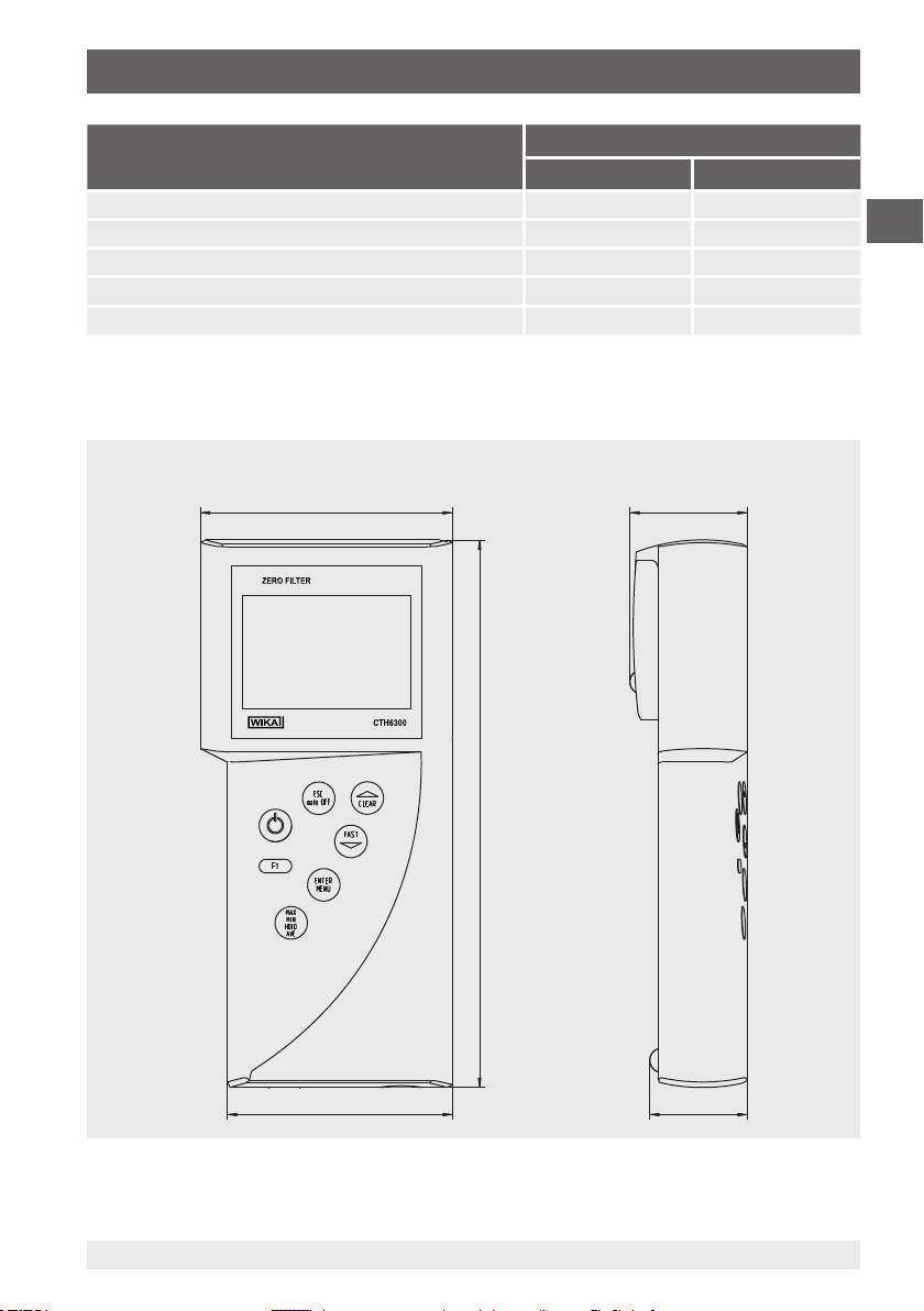
44 (1.73)
93 (3.66)
3. Specifications
Standard probe (immersion probe) Temperature range
°C °F
Pt100, d = 3 mm, l = 150 mm (d = 0.12 in, l = 5.91 in) -200 ... +450 -392 ... +842
Pt100, d = 3 mm, l = 300 mm (d = 0.12 in, l = 11.81 in) -200 ... +450 -392 ... +842
Pt100, d = 6 mm, l = 300 mm (d = 0.24 in, l = 11.81 in) -200 ... +450 -392 ... +842
TC K, d = 3 mm, l = 300 mm (d = 0.12 in, l = 11.81 in) -200 ... +1,100 -392 ... +2,012
TC K, d = 3 mm, l = 500 mm (d = 0.12 in, l = 19.69 in) -200 ... +1,100 -392 ... +2,012
Dimensions in mm (in)
Front view Side view (left)
EN
83 (3.27)
2079988.08 02/2018 EN/DE/IT
WIKA operating instructions, models CTH6300 and CTH6500
202 (7.95)
37 (1.46)
11
Page 12

3. Specifications / 4. Design and function
Bottom view (1-channel instrument)
EN
4. Design and function
4.1 Description
Universally applicable hand-held thermometers for demanding, mobile temperature
measurement, distinguished by flexibility and easy handling. In addition to Pt100
resistance thermometers, they can also process signals from typical thermocouples. Thus
temperatures from -200 ... +1,500 °C (-392 ... +2,732 °F) can be measured.
Low-drift measuring amplifiers ensure small measurement errors, while easy-to-use
adjustment features considerably simplify adjustments and calibrations:
■
Calibration by code for fast setting of standard probes via key data
■
Physical calibration of probe and display at one, two or three different temperatures
In this way it is possible to reduce measuring errors to a minimum and ensure a high
indication accuracy.
Hand-held thermometer, model CTH6300, industrial version
Its design makes the CTH6300 especially suitable for the commissioning, maintenance
and service/calibration of temperature instruments and equipment.
Hand-held thermometer, model CTH6500, precision version
Due to its high accuracy of 0.03 K in the range from -100 ... +150 °C (-148 ... +302 °F), the
CTH6500 can be used as a reference instrument in the biotechnology, pharmaceutical
and food industries. The CTH6500 is thus ideal for all service and maintenance tasks.
4.2 Scope of delivery
CTH6300
■
Hand-held thermometer, model CTH6300, industrial version, incl. 9 V battery
■
3.1 calibration certificate per DIN EN 10204
■
Choice of temperature probes
12
WIKA operating instructions, models CTH6300 and CTH6500
2079988.08 02/2018 EN/DE/IT
Page 13
4. Design and function
CTH6500
■
Hand-held thermometer, model CTH6500, precision version, incl. 9 V battery
■
3.1 calibration certificate per DIN EN 10204
■
Choice of temperature probes
Cross-check scope of delivery with delivery note.
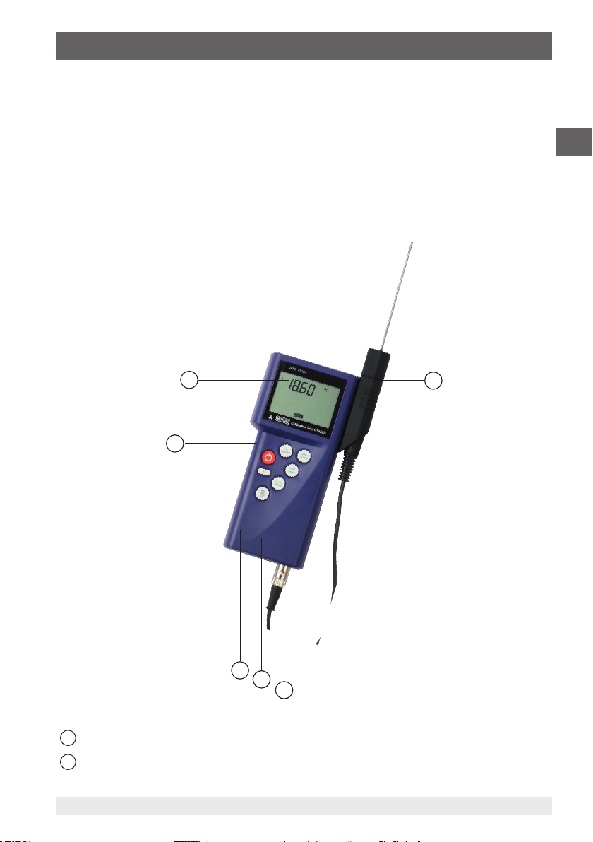
4.3 Operating and display elements
EN
1
Probe holder
2
2079988.08 02/2018 EN/DE/IT
First connection port for temperature probe
6
1
5
4
3
2
WIKA operating instructions, models CTH6300 and CTH6500
13
Page 14
4. Design and function
3
Second connection port for temperature probe
4
USB connection port for PC
5
EN
Keypad
6
Large LC display
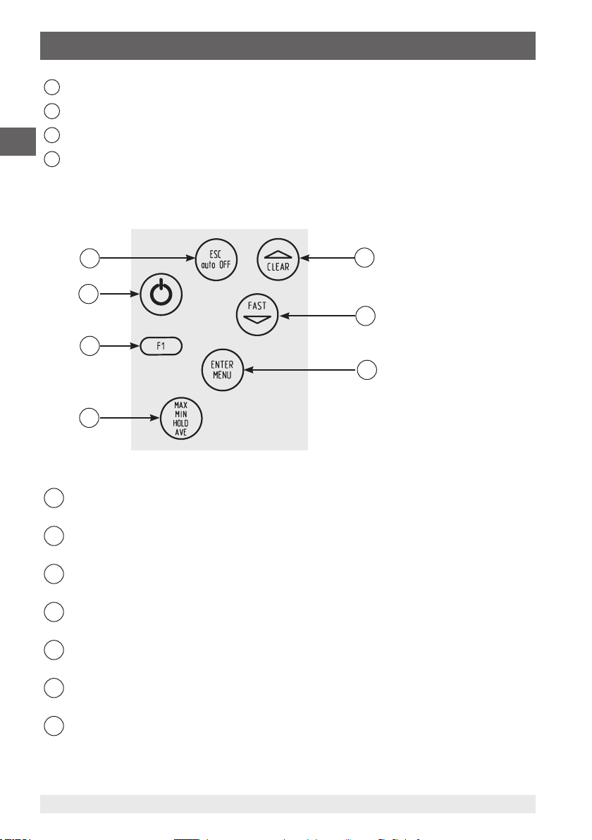
4.4 Keypad
7
6
5
4
Arrow key CLEAR
1
Selection of menu items
Arrow key FAST
2
Selection of menu items
ENTER/MENU key
3
Access to the main menu, confirming the function
MIN/MAX/HOLD/AVE key
4
Setting MIN and MAX, HOLD and AVE
Function keys
5
Configuring the instrument
ON/OFF key
6
Turning the instrument on and off
ESC key
7
Back to measuring mode
1
2
3
14
2079988.08 02/2018 EN/DE/IT
WIKA operating instructions, models CTH6300 and CTH6500
Page 15
4. Design and function
4.5 Voltage supply
The battery life is approx. 20 hours for continuous operation.
The BAT segment indicates that the battery must be replaced soon. From this point,
correct measurements can be performed for approx. 1 hour. A 9 V battery is used as
voltage supply of the instrument. For information on the battery see chapter 4.6 “Battery
replacement”.
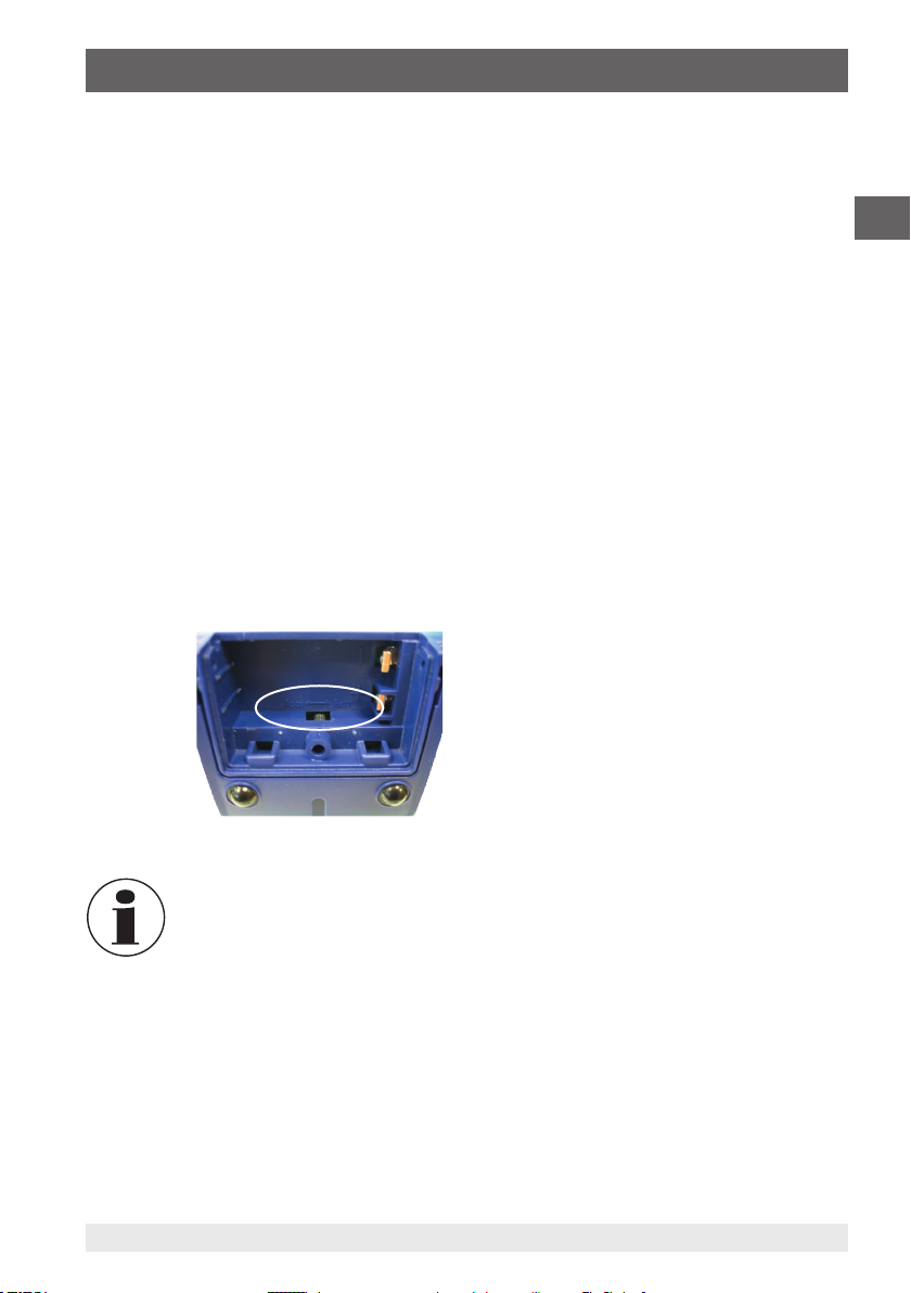
4.6 Battery replacement
For battery replacement switch off the instrument and open the battery compartment
attached on the rear side. After that remove the battery and disconnect the connection
cable. Then insert the new batteries into the battery compartment.
Switch in the battery compartment on the rear side allows to specify whether the
instrument is operated with a battery or a rechargeable battery.
■
With the setting Batt, the charging current supplied via USB interface is not directed to
the battery, so that this does not damage it.
■
With the setting Accu, the rechargeable battery is charged only via the USB interface.
While the rechargeable battery is supplied with a charging current, this is not, however,
enough to charge the battery fully.
EN
If the instrument is not used for a long time, remove the battery.
When closing the battery compartment make sure that the battery
connection wires are not jammed or damaged.
2079988.08 02/2018 EN/DE/IT
WIKA operating instructions, models CTH6300 and CTH6500
15
Page 16
4. Design and function
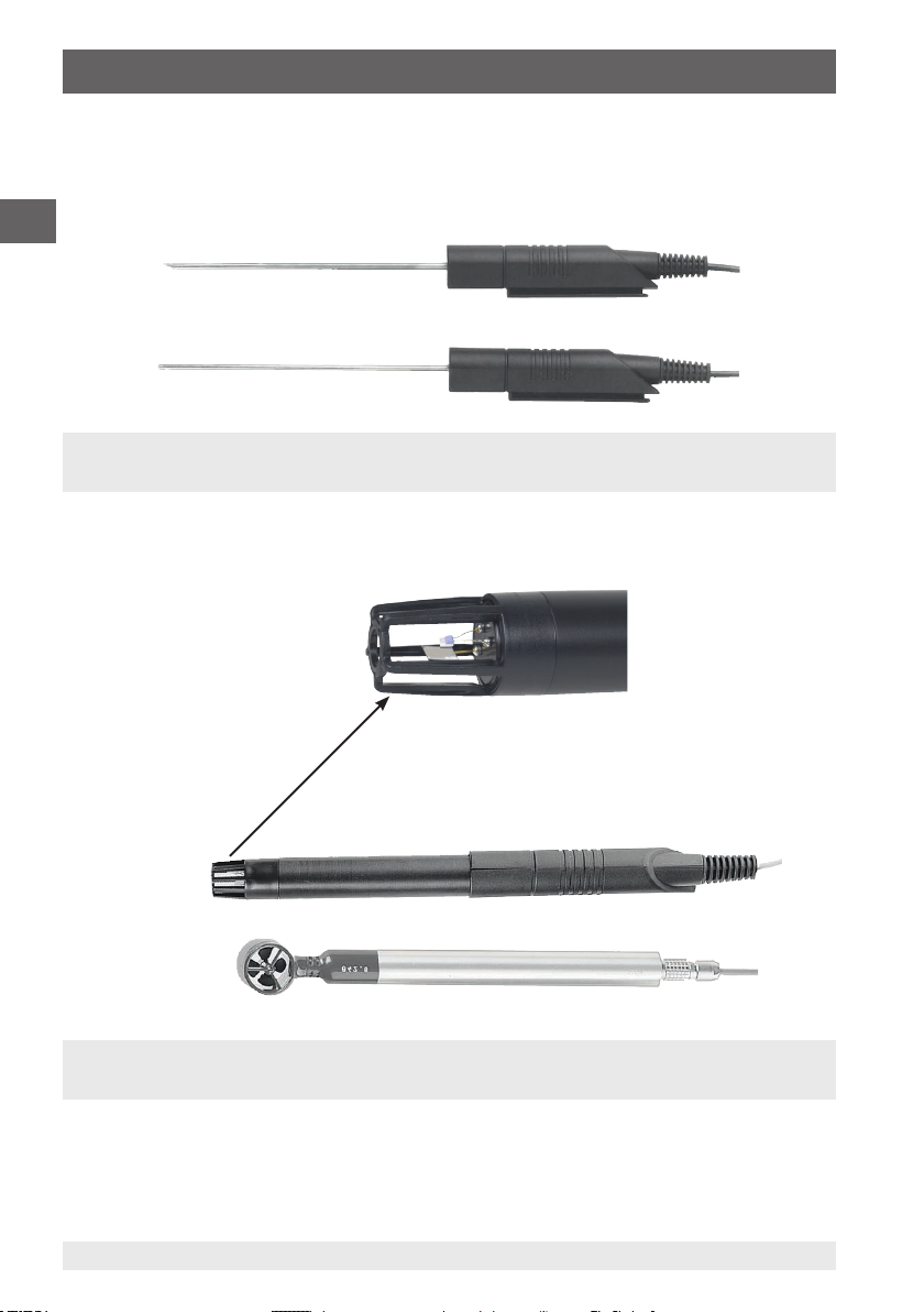
4.7 Temperature probes
Different connection options of different temperature probes guarantee flexibility.
Temperature probes for model CTH6300/CTH6500
EN
Fig. top: penetration probe
Fig. bottom: immersion probe
Additional temperature probes for model CTH6500
Section through the
combined temperaturehumidity probe
Fig. top: combined temperature-humidity probe
Fig. bottom: vane flow probe
16
WIKA operating instructions, models CTH6300 and CTH6500
2079988.08 02/2018 EN/DE/IT
Page 17
4. Design and function
4.8 Connecting/replacing the temperature probe
WARNING!
Only use the supplied temperature probes!
▶
Switch off the instrument for probe replacement.
▶
Before switching the instrument on, connect the probe, otherwise it may
not be correctly identified by the instrument.
The digital instrument and the temperature probe are connected to each other electrically
by means of a separate connection cable. For probe replacement, it is preferable to use
the 8-pin plug contact at the probe.
■
To connect a temperature probe to the hand-held thermometer plug the 8-pin plug
connection according to the guiding into the connection port for temperature probes.
■
Connect the connector without crossing the threads. If the connector is positioned
correctly, it can be plugged in without any significant effort.
■
To disconnect the probe, do not pull on the cable, but rather only on the connector
sleeve.
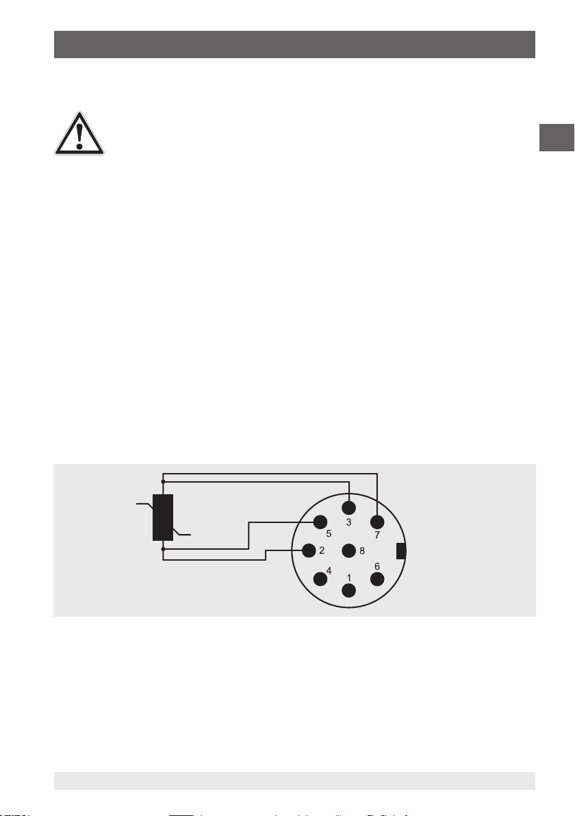
4.9 Connector assignment
4.9.1 Probe connection, Pt100, 4-wire
Measuring channel 1 and 2
EN
Pt100 4-wire
Soldering side
2079988.08 02/2018 EN/DE/IT
WIKA operating instructions, models CTH6300 and CTH6500
17
Page 18
4. Design and function
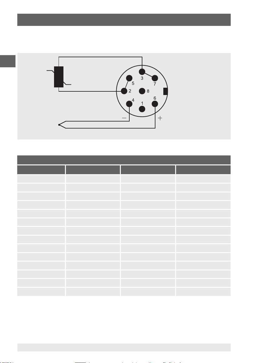
4.9.2 Probe connection, thermocouple
Measuring channel 1 and 2
EN
Pt100 2-wire
Soldering side
NiCr-Ni thermocouple
International colour code for thermocouples
Thermocouple DIN 43722 DIN 43710 ANSI MC 96.1
Type R orange white green
Pt13Rh-Pt + orange - white + red - white + black - red
Type S orange white green
Pt10Rh-Pt + orange - white + red - white + black - red
Type J black black
Fe-CuNi + black - white + white - red
Type T brown blue
Cu-CuNi + brown - white + blue - red
Type K green green yellow
NiCr-Ni + green - white + red - green + yellow - red
Type N pink
NiCrSi-NiSi + pink - white
Type L brown
Fe-CuNi + red - blue
18
2079988.08 02/2018 EN/DE/IT
WIKA operating instructions, models CTH6300 and CTH6500
Page 19
4. Design and function
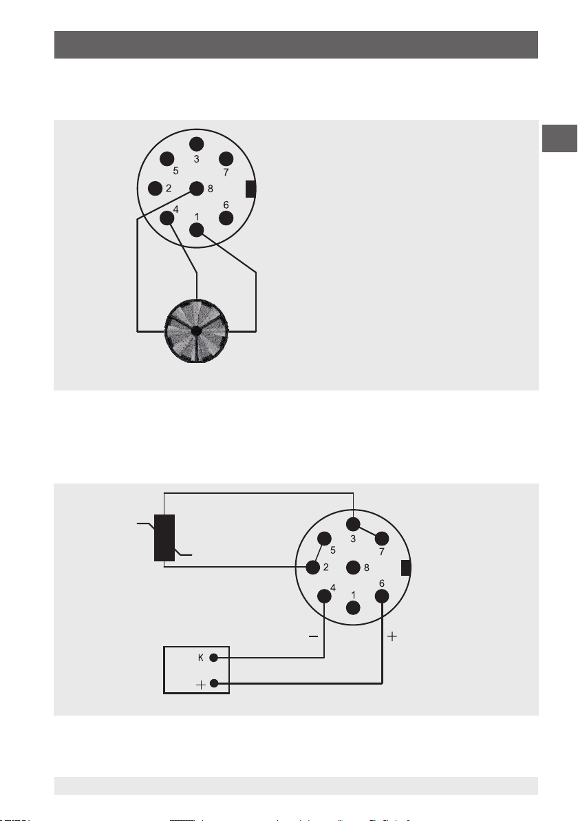
4.9.3 Probe connection, Vane, Mini Air
Measuring channel 1 and 2
Soldering side
blackwhiteyellow
Mini Air vane
EN
4.9.4 Adapter, DIN connector to thermocouple terminal
Measuring channel 1 and 2
Pt100 2-wire
gn (ws)
Miniature
thermocouple
terminal
rt (gn) Cable length 12 cm
2079988.08 02/2018 EN/DE/IT
WIKA operating instructions, models CTH6300 and CTH6500
Soldering side
19
Page 20

5. Transport, packaging and storage
5. Transport, packaging and storage
5.1 Transport
Check hand-held thermometer for any damage that may have been caused by transport.
EN
Obvious damage must be reported immediately.
5.2 Packaging
Do not remove packaging until just before mounting.
Keep the packaging as it will provide optimum protection during transport (e.g. change in
installation site, sending for repair).
5.3 Storage
Permissible conditions at the place of storage:
■
Storage temperature: -10 ... +50 °C (14 ... 122 °F)
■
Relative humidity: 35 ... 85 % r. h. (non-condensing)
Avoid exposure to the following factors:
■
Direct sunlight or proximity to hot objects
■
Mechanical vibration, mechanical shock (putting it down hard)
■
Soot, vapour, dust and corrosive gases
■
Hazardous environments, flammable atmospheres
Store the hand-held thermometer in its original packaging in a location that fulfils the
conditions listed above. If the original packaging is not available, pack and store the
instrument as described below:
1. Wrap the instrument in an antistatic plastic film.
2. Place the instrument, along with shock-absorbent material, in the packaging.
3. If stored for a prolonged period of time (more than 30 days), place a bag containing a
desiccant inside the packaging.
WARNING!
Before storing the instrument (following operation), remove any residual
media. This is of particular importance if the medium is hazardous to health,
e.g. caustic, toxic, carcinogenic, radioactive, etc.
20
WIKA operating instructions, models CTH6300 and CTH6500
2079988.08 02/2018 EN/DE/IT
Page 21

6. Commissioning, operation
6. Commissioning, operation
6.1 Commissioning
Before switching on, connect the measuring probe(s) to the intended female connector
of the measuring instrument and make sure that a fully charged 9 V battery is inserted (2
batteries are included in the scope of delivery). The probe connection sockets are marked
on the instrument case with 1 or 2 correspondingly. The USB interface is marked next to
them.
6.2 Switching on/Switching off
To switch the measuring instrument on and off, press the ON/OFF key. After switching
the instrument on all segments are indicated on the display for approx. 1.5 seconds (full
segment indication). For the next approx. 1.5 seconds the instrument indicates the set
probe calibration code as well as the set measurement parameter for channel 1 (e.g.
CoFF for DIN characteristic curve and P for Pt100). After that the calibration data for the
2nd channel are displayed.
Finally, the instrument switches automatically to the measuring mode and displays the
current measurement parameter. In the upper display line (large display) the measured
value is displayed, a bar graph is located beneath it for graphical measured value
representation. In all 2-channel instruments the 2nd channel is displayed in the lower
display line (small display).
EN
Channel 1
Line 1: CoFF P = calibration on channel 1 per DIN, probe selection set to Pt100.
Channel 2
Line 2: CoFF P = calibration on channel 2 per DIN, probe selection set to Pt100.
2079988.08 02/2018 EN/DE/IT
WIKA operating instructions, models CTH6300 and CTH6500
21
Page 22
6. Commissioning, operation
For all measuring instruments the measuring channels can be selected
according to the model-specific measurement parameters. For the version
with only one probe the correct measurement parameter is already set.
EN
When using measuring instruments with several channels and/or different
probes make sure that the correct measurement parameter is set. See
chapter 6.4.2 “Probe selection Prob”.
6.3 Menu structure and settings
Instrument settings such as measurement parameters, probe calibration, channel
deactivation, arrow keys, etc. are adjusted using a menu tree.
■
To open the main menu, press the ENTER/MENU key.
■
The ▲▼ arrow keys are used to select the desired menu items.
■
By pressing ESC, one returns to the measuring mode.
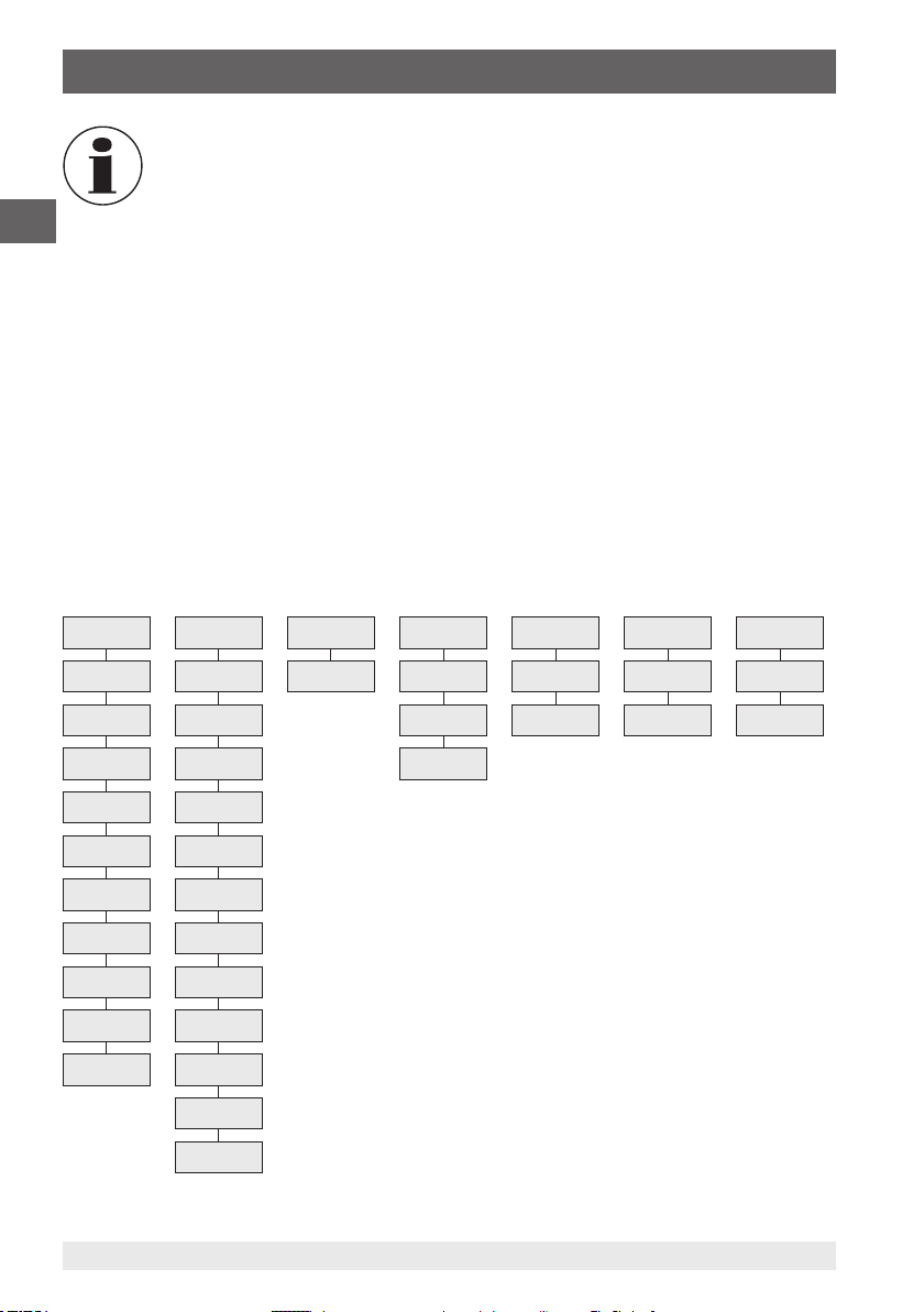
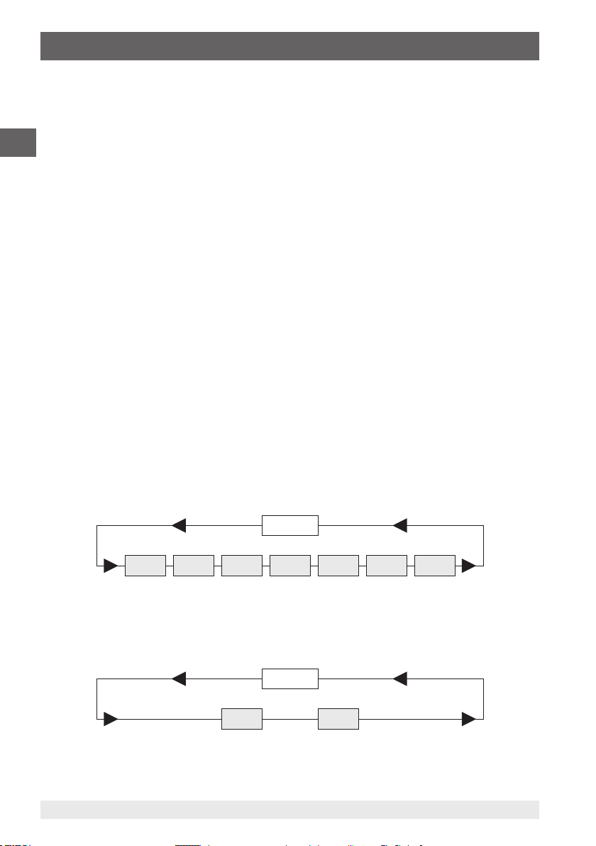
6.4 Menu tree
Unit Prob Lin2 CAL Chnl ArEA Lo6
°C P T1-T2 OFF OFF c OFF
°F J oP1 ON m ON
m/s K oP2
%rh L
g/m³ N
°C td R
°F td S
Pa T
hPa RH
m³/s D
22
Pr
H
2079988.08 02/2018 EN/DE/IT
WIKA operating instructions, models CTH6300 and CTH6500
Page 23
6. Commissioning, operation
6.4.1 Unit switching °C and °F or % rH, td or g/m³ [Unit]
Unit
Measuring unit temperature (°C = Celsius, °F = Fahrenheit)
Measuring unit humidity (% rH = relative humidity, td = dew point, g/m³ = absolute
humidity)
1. Press the ENTER/MENU key and select Unit using the ▲▼ arrow keys.
2. Press the ENTER/MENU key once again.
A small 1 appears on the left side of the display, it indicates the channel. (Channel
⇒
selection is only possible with 2-channel instruments).
3. Use the ▲▼ arrow keys to select the channel for which the displayed unit needs to be
changed.
4. Confirm by pressing ENTER/MENU.
Depending on the set probe, °C/°F or % rH/td/gm³ is displayed on the right side of
⇒
the display (see chapter 6.4.2 “Probe selection Prob”).
5. Select the required unit using the ▲▼ arrow keys and confirm it by pressing ENTER/
MENU.
6. Use ESC to return to the measuring mode.
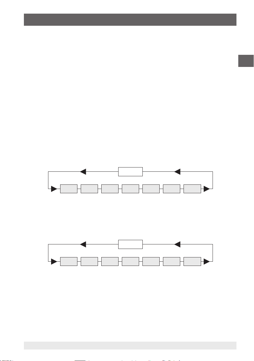
MENU
Unit Prob Lin2 CAL Chnl ArEA Lo6
EN
6.4.2 Probe selection Prob
1. Press the ENTER/MENU key and select Prob using the ▲▼ arrow keys.
2. Press the ENTER/MENU key once again.
MENU
Unit Prob Lin2 CAL Chnl ArEA Lo6
A small 1 appears on the left side of the display, it indicates the channel.
⇒
3. Using the ▲▼ arrow keys, switch the channel for which a probe should be selected.
4. Confirm the selection by pressing ENTER/MENU.
5. Now select the following probes using the ▲▼ arrow keys (see following table):
2079988.08 02/2018 EN/DE/IT
WIKA operating instructions, models CTH6300 and CTH6500
23
Page 24

6. Commissioning, operation
Measurement parameter Probe selection (Prob) LC display
Temperature Pt100 (RTD)
EN
Temperature Fe-CuNi type J
Temperature NiCr-Ni type K
Temperature Fe-CuNi type L
Temperature NiCrSi-NiSi type N
Temperature Pt13Rh-Pt type R
Temperature Pt10Rh-Pt type S
Temperature Cu-CuNi type T
Humidity % r. h.
Flow m/s
Pressure Pa
Hot wire m/s
P
)
L
R
S
r
h
d
PR
H
6. Press ENTER/MENU to confirm the desired setting.
7. Use ESC to return to the measuring mode.
Make sure that the correct measurement parameter is set for the connected
probe. If a measurement parameter is changed in the Prob menu and the
change is confirmed by pressing the Enter key, the standard calibration is
used automatically.
Note on combined probes (temperature and humidity):
Ensure that “relative humidity” is set as a measurement parameter for the
measuring channel to which the combined probe is connected.
24
WIKA operating instructions, models CTH6300 and CTH6500
2079988.08 02/2018 EN/DE/IT
Page 25

6. Commissioning, operation
If the temperature value of the connected combined probe is to be displayed
as well, deactivate the channel to which no combined probe is connected
(see chapter 6.4.5 “Activating/deactivating measuring channels [Chnl] (only
for 2-channel instruments)”)”.
6.4.3 Activating/deactivating differential temperature display option [Lin2]
(only for 2-channel instruments)
1. Press the ENTER/MENU key and select Lin2 using the ▲▼ arrow keys.
2. Press the ENTER/MENU key once again.
3. Now activate or deactivate the display “Differential temperature” T1-T2 using the ▲▼
arrow keys.
If
⇒
4. Press ENTER/MENU to confirm the desired setting.
5. Use ESC to return to the measuring mode.
is visible on the LC display, the differential temperature is active.
T1-T2
MENU
Unit Prob Lin2 CAL Chnl ArEA Lo6
To display differential temperature, both channels must be activated.
EN
6.4.4 Calibration mode CAL
This measuring instrument offers the possibility to perform a simple calibration when
replacing the probes in order to compensate the manufacturer-specific tolerances of the
probes and guarantee a consistently high accuracy for your measuring chain.
The instrument has 3 different calibration modes:
[OFF]: Standard characteristic curve
for example, for Pt100 resistance measurements DIN IEC 60751
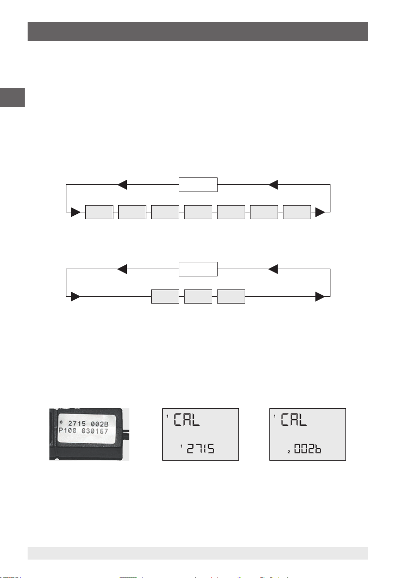
oP1: Calibration by code
The 2 x 4-digit code, clearly and visibly displayed on the handles of our probes,
corresponds to a 2-point calibration
oP2: Physical calibration
Calibration with reference standards: 1-point, 2-point or 3-point calibration
possible
2079988.08 02/2018 EN/DE/IT
WIKA operating instructions, models CTH6300 and CTH6500
25
Page 26
6. Commissioning, operation
The current calibration coefficients are shown in the accompanying traceable calibration
certificate.
CAL = calibrate
EN
1. Press the ENTER/MENU key and select CAL using the ▲▼ arrow keys.
2. Press the ENTER/MENU key once again.
A small 1 appears on the left side of the display, it indicates the channel.
⇒
3. Use the ▲▼ arrow keys to select the channel (1 or 2) to be calibrated (channel
selection only possible with 2-channel instruments).
4. Confirm the selection by pressing ENTER/MENU.
MENU
Unit Prob Lin2 CAL Chnl ArEA Lo6
5. Now use the ▲▼ arrow keys to select the desired calibration function.
CAL
CoFF oP1 oP2
Standard linearisation in accordance with DIN IEC 60751 [oFF
1. Use the ▲▼ arrow keys to select CoFF.
2. Press ENTER/MENU to confirm the desired setting.
3. Use ESC to return to the measuring mode.
Calibration by code oP1
1. Use the ▲▼ arrow keys to select oP1.
2. Press ENTER/MENU to confirm the desired setting.
A small 1 appears in the lower part of the display. 4 characters follow it (hex code
⇒
/ 0 ... F).
26
WIKA operating instructions, models CTH6300 and CTH6500
2079988.08 02/2018 EN/DE/IT
Page 27
6. Commissioning, operation
3. Change the 4 characters using the ▲ arrow key.
4. Press the ▼ arrow key to go to the next position.
5. When all 4 characters are entered as required, confirm by pressing ENTER/MENU.
A small 2 appears and the following 4 characters can be changed as well.
⇒
6. Use ESC to return to the measuring mode.
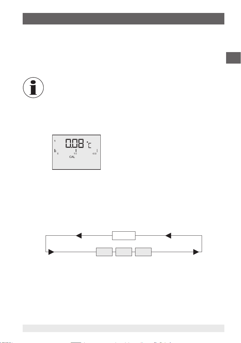
When accessing oP1 using ENTER/MENU, the oP1 function (calibration by
code) is activated, even if the menu has been exited by pressing ESC.
Example of the measured value display after entering a probe calibration code:
The small 1 in the left corner, in combination with the display segment CAL in the centre
of the display, indicates that the calibration by code oP1 has been activated.
EN
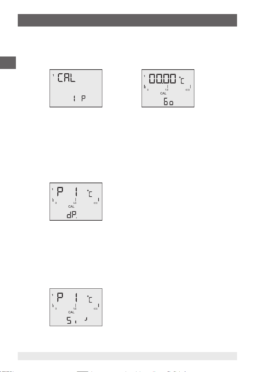
Physical calibration oP2
1. Use the ▲▼ arrow keys to select oP2.
2. Press ENTER/MENU to confirm the desired setting.
1 P is displayed in the lower part of the display.
⇒
3. Use the ▲▼ arrow keys to select from 1-point 1 P-, 2-point 2 P- and 3-point 3
P-calibration.
oP2
1 P 2 P 3 P
2079988.08 02/2018 EN/DE/IT
WIKA operating instructions, models CTH6300 and CTH6500
27
Page 28
6. Commissioning, operation
Example of 1-point calibration:
1. Confirm 1-point calibration 1 P by pressing ENTER/MENU.
Go appears on the display.
⇒
2. Once the measured value is stable, confirm by pressing ENTER/MENU.
EN
After approx. 2 seconds P1 appears in the first display line for measured value 1, dP
appears in the 2nd line for the decimal point.
3. Use the ▲▼ arrow keys to select the desired number of decimal places:
d P. = two decimal places
dP . = one decimal place (decimal point moves one position to the right)
4. Press ENTER/MENU to confirm the desired setting.
Si_ appears on the display.
⇒
5. Use the ▲▼ arrow keys to select the sign:
Si_ = the number to be entered is in the negative range (below 0.00 °C)
Si┘= the number to be entered is in the positive range
28
WIKA operating instructions, models CTH6300 and CTH6500
2079988.08 02/2018 EN/DE/IT
Page 29
6. Commissioning, operation
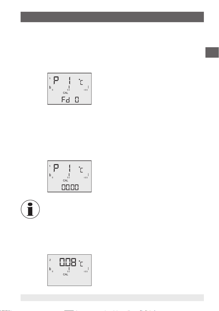
6. Press ENTER/MENU to confirm the desired setting.
Fd 0 appears on the display.
⇒
7. Use the ▲▼ arrow keys to select the range.
Fd 0 = below 1,000 °C
Fd 1 = above 1,000 °C
8. Press ENTER/MENU to confirm the desired setting.
00.00 appears on the display (or similar).
⇒
9. Enter the temperature of the reference at this point.
10. Change the digits using the ▲ arrow key.
11. Use the ▼ arrow key to switch to the next digit.
12. After completing the input of the temperature, confirm by pressing ENTER/MENU.
13. Use ESC to return to the measuring mode.
The physical calibration oP2 cannot be cancelled using the ESC key. If
required, the calibration can be cancelled by switching off the measuring
instrument.
EN
Example of the measured value display after physical calibration against a
reference standard:
The small 2 in the left corner, in combination with the display segment CAL in the centre
of the display, indicates that the physical probe calibration oP2 has been activated.
2079988.08 02/2018 EN/DE/IT
WIKA operating instructions, models CTH6300 and CTH6500
29
Page 30
6. Commissioning, operation
6.4.4.1 Calibration function combined probe (humidity/temperature), CAL
All humidity probes by WIKA are combined probes.
This means that besides the humidity sensor they also contain a temperature sensor.
Both measurement parameters are connected to the same measuring channel using one
EN
probe connector. To calibrate both measurement parameters, humidity and temperature,
the measurement parameter rH (rel. humidity) must first be set (see chapter 6.4.2 “Probe
selection Prob”).
The instrument has 3 different calibration modes:
OFF Standard characteristic curve
no probe-specific correction is performed
oP1 Calibration by code
The 2 x 4-digit code, clearly and visibly displayed on the handles of our probes
(rH = humidity and P °C = temperature), corresponds to a 2-point calibration
oP2 Physical calibration
Calibration with reference standards: 1-point, 2-point or 3-point calibration is
only possible for the measurement parameter rH humidity.
CAL = calibrate
1. Press the ENTER/MENU key and select CAL using the ▲▼ arrow keys.
2. Press the ENTER/MENU key once again.
A small 1 appears on the left side of the display, it indicates the channel.
⇒
3. Use the ▲▼ arrow keys to select the channel (1 or 2) to be calibrated.
4. Confirm the selection by pressing ENTER/MENU.
MENU
Unit Prob Lin2 CAL Chnl ArEA Lo6
5. Now use the ▲▼ arrow keys to choose between rH for humidity calibration and P °C
for temperature calibration.
CAL
rH P°C
30
WIKA operating instructions, models CTH6300 and CTH6500
2079988.08 02/2018 EN/DE/IT
Page 31

6. Commissioning, operation
6. Use the ▲▼ arrow keys to select the desired calibration function.
CAL
CoFF oP1 oP2
Standard characteristic curve oFF
1. Use the ▲▼ arrow keys to select oFF.
2. Press ENTER/MENU to confirm the desired setting.
3. Use ESC to return to the measuring mode.
Calibration by code oP1
1. Use the ▲▼ arrow keys to select oP1.
2. Press ENTER/MENU to confirm the desired setting.
A small 1 appears in the lower part of the display. 4 characters follow it (hex code
⇒
/ 0 ... F).
3. Change the 4 characters using the ▲ arrow key.
4. Press the ▼ arrow key to go to the next position.
5. When all 4 characters are entered as required, confirm by pressing ENTER/MENU.
A small 2 appears and the following 4 characters can be changed as well.
⇒
6. Use ESC to return to the measuring mode.
EN
6.4.5 Activating/deactivating measuring channels [Chnl] (only for 2-channel
instruments)
Chnl = Channel = select
1. Press the ENTER/MENU key and select Chnl using the ▲▼ arrow keys.
2. Press the ENTER/MENU key once again.
A small 1 appears on the left side of the display, it indicates the channel.
⇒
3. Use the ▲▼ arrow keys to select the channel to be activated or deactivated.
4. Confirm the selection by pressing ENTER/MENU.
2079988.08 02/2018 EN/DE/IT
WIKA operating instructions, models CTH6300 and CTH6500
31
Page 32

6. Commissioning, operation
5. Now use the ▲▼ arrow keys to activate on or deactivate off the set channel.
6. Press ENTER/MENU to confirm the desired setting.
7. Use ESC to return to the measuring mode.
EN
Alternative: keep the HOLD/MAX/MIN/AVE key pressed for 2 seconds; this deactivates
or activates channel 2.
MENU
Unit Prob Lin2 CAL Chnl ArEA Lo6
At least one channel is always active!
6.4.6 Area entry for volume flow [ArEA]
The area dimensions can be entered only on instruments for flow measurement.
1. Press the ENTER/MENU key and select ArEA using the ▲▼ arrow keys.
2. Press the ENTER/MENU key once again.
A small 1 appears on the left side of the display, it indicates the channel.
⇒
3. Use the ▲▼ arrow keys to select the channel.
4. Confirm the selection by pressing ENTER/MENU.
5. Use the ▲▼ arrow keys to select the unit of measure:
c = centimeter²
m = meter²
6. Confirm the selection by pressing ENTER/MENU.
00.00 is displayed now in the lower line of the display.
⇒
7. Change the blinking number by pressing the ▲ arrow key.
8. Press the ▼ arrow key to go to the next position.
9. Confirm the input by pressing ENTER/MENU.
10. Use ESC to return to the measuring mode.
MENU
Unit Prob Lin2 CAL Chnl ArEA Lo6
32
WIKA operating instructions, models CTH6300 and CTH6500
2079988.08 02/2018 EN/DE/IT
Page 33

6. Commissioning, operation
6.4.7 Storage management [Lo6] (not possible for CTH6300)
1. Press the ENTER/MENU key and select Lo6 using the ▲▼ arrow keys (only when the
data logger version has been ordered).
2. Press the ENTER/MENU key once again.
OFF is shown in the lower line of the display.
⇒
3. Now use the ▲▼ arrow keys to start the logger mode with ON.
4. Confirm the selection by pressing ENTER/MENU.
MENU
Unit Prob Lin2 CAL Chnl ArEA Lo6
5. Use the ▲▼ arrow keys to choose between the automatic Auto or manual SPot
memory.
6. Confirm by pressing ENTER/MENU.
7. Decide between adding or creating a new log file by selecting Add or nLo6.
When selecting the automatic memory, there is a prompt to select the measuring
⇒
interval:
1S = 1 second 1M = 1 minute
5S = 5 seconds 2M = 2 minutes
10S = 10 seconds 5M = 5 minutes
20S = 20 seconds 10M = 10 minutes
30S = 30 seconds 20M = 20 minutes
EN
8. Confirm the input by pressing ENTER/MENU.
9. Use ESC to return to the measuring mode.
Manual saving using SPot. Press the ESC key to save individual measured values
manually.
6.5 Memory request [HOLD-MAX-MIN-AVE]
After pressing the HOLD-MAX-MIN-AVE key for the first time, the current measured
values at the moment of actuation are “frozen” and indicated on the display as hold
values. Press this key repeatedly to request saved maximum, minimum and average
values in the lower line (small display).
2079988.08 02/2018 EN/DE/IT
WIKA operating instructions, models CTH6300 and CTH6500
33
Page 34

6. Commissioning, operation
Note for 2-channel instruments:
After displaying the hold values for both channels (large and small display),
the MAX-MIN-AVE values of the first channel are displayed in the lower line
EN
Clear memory (MAX-MIN-AVE)
▶
Press the CLEAR key once.
6.6 Change measurement cycle (FAST mode)
1. Press the FAST/▼ key once.
2. Press FAST/▼ key again
(small display), after that, the values of the second channel are displayed. If
only one probe is connected to a 2-channel measuring instrument, deactivate
the 2nd channel (see chapter 6.4.5 “Activating/deactivating measuring
channels [Chnl] (only for 2-channel instruments)”).
During the memory request, the extremes MAX-MIN and the average value
AVE are not updated or calculated.
Clr appears on the display. All extremes (MAX-MIN and AVE) measured up to
⇒
this moment are deleted. After deletion of the memory the measuring instrument
switches back to the measuring mode automatically.
Fast mode is initiated. The measuring instrument measures 4 times per second
⇒
now.
Return to the normal mode with 1 measured value per second again.
⇒
Note that the battery consumption in the Fast mode is approximately three
times higher than it is in the normal mode.
This setting is deactivated by switching off.
6.7 AUTO-OFF function
1. Press the ESC-AUTO-OFF key.
dAoF will be shown on the display. The Auto-Off function is deactivated now.
⇒
2. Press the ESC-AUTO-OFF key.
EAoF will be shown on the display. The measuring instrument is shut down
⇒
automatically after 30 minutes.
dAoF = Disable Auto-off
EAoF = Enable Auto-off
34
2079988.08 02/2018 EN/DE/IT
WIKA operating instructions, models CTH6300 and CTH6500
Page 35

6. Commissioning, operation / 7. USB interface protocol
This setting is deactivated by switching off (default setting is EAoF).
6.8 Special functions
6.8.1 Ohm/Microvolt/Volt/Hertz display
To display the indicated values in the corresponding basic unit, during switching on
simultaneously press the FAST/▼ key and the ON/OFF key and keep them pressed for
approx. 3 seconds until the following basic unit is displayed:
o = Ohm (Pt100)
H = Hertz (flow m/s)
u = Microvolt (thermocouples)
U = Volt (humidity)
6.8.2 Zero adjustment (zero)
Keep the Clear key pressed (for approx. 3 seconds) to set the displayed value to 0.
Before pressing the key make sure that the actual value is also 0 (no flows/pressure
present at the probe).
6.8.3 Deactivation of channel 2 (toggle)
Keep the Hold key pressed (for approx. 3 seconds) to deactivate or activate the 2nd
measuring channel.
7. USB interface protocol
EN
With the CTH6x00 instrument series, a USB-/RS-232 driver from the manufacturer FTDI
is used.
Parameters
Baud rate 2,400 baud
Data bits 8
Stop bits 2
Parity None
2079988.08 02/2018 EN/DE/IT
WIKA operating instructions, models CTH6300 and CTH6500
35
Page 36

7. USB interface protocol
To transfer the measured values, the following requests must be sent to the measuring
instrument. The following table illustrates which values can be requested via the interface.
CTH6500
EN
Recognise MEASURED VALUE 1 + 2 automatically
Processor version 6E (hex) 110 (dez.) n (ASCII)
Instrument type - - V (ASCII)
Instrument serial number - 83 (dez.) S (ASCII)
Read storage (only for instruments with
data logger)
Enable keyboard 0 (hex) 0 (dez.) -
Command clarification
Commands must each be finished with Cr Lf (0D 0A or Hex value &0D&0A)
■
“FC” (hex) delivers the current data set e.g. “23.351 25.462”
■
“S” delivers the serial number e.g. “79506000108”
■
“n” delivers the version, e.g. “V3.03”
■
“l” (lower-case l) Read – delivers a dump of all values from the memory in the format
e.g. “23.35 25.46 Cr Lf”
FC (hex) 252 (dez.) ü (ASCII)
6C (hex) 108 (dez.) l (ASCII)
If data are read out from the instrument using the FC (hex) command, the
keyboard is locked. It can be enabled again using the 0 (hex) command.
The data are sent by the instrument in the following format.
Data type = String
The string length depends on whether it is a 1-channel or a 2-channel instrument. With a
2-channel instrument, the string can only be a max. 18 characters long.
36
WIKA operating instructions, models CTH6300 and CTH6500
2079988.08 02/2018 EN/DE/IT
Page 37

8. Maintenance, cleaning and recalibration / 9. Faults
8. Maintenance, cleaning and recalibration
8.1 Maintenance
These hand-held thermometers are maintenance-free.
Repairs must only be carried out by the manufacturer.
This does not apply to the battery replacement.
8.2 Cleaning
CAUTION!
■
Before cleaning, switch off and disconnect the hand-held thermometer
from the mains.
■
Clean the instrument with a moist cloth.
■
Do not use any aggressive cleaning agents.
■
Electrical connections must not come into contact with moisture.
■
Wash or clean the dismounted instrument or temperature probe before
returning it, in order to protect persons and the environment from exposure
to residual media.
■
Residual media at the dismounted hand-held thermometer and/or
temperature probe can result in a risk to persons, the environment and
equipment. Take sufficient precautionary measures.
EN
For information on returning the instrument see chapter 10.2 “Return”.
8.3 Recalibration
DKD/DAkkS certificate - official certificates:
We recommend that the instrument is regularly recalibrated by the manufacturer, with
time intervals of approx. 12 months. The basic settings will be corrected if necessary.
9. Faults
In the event of maloperation or faults the instrument helps the operator by means of the
following error messages.
Display Cause Measures
Wrong probe or no probe connected Connect probe or connect correct
open
2079988.08 02/2018 EN/DE/IT
WIKA operating instructions, models CTH6300 and CTH6500
probe.
37
Page 38

9. Faults
Display Cause Measures
“too low” underrange of the
7olo
measuring range
EN
“too high” overrange of the
7o
h
measuring range
'
Temperature of the reference
7E
r
7Er2
E15
E19
E1dh
E16
E1oh
E1eh
E23
measuring point exceeds the upper
i
limit of the measuring range
Temperature of the reference
measuring point is below the lower
limit of the measuring range
Battery is completely discharged Insert new batteries
Interruption of the Auto-o function Switch on the Auto-o function
EE-prom content destroyed Send in for repair
Use the temperature probe according
to the technical specications. See
chapter 3 “Specications”.
Use the temperature probe according
to the technical specications. See
chapter 3 “Specications”.
Use the temperature probe according
to the technical specications. See
chapter 3 “Specications”.
Use the temperature probe according
to the technical specications. See
chapter 3 “Specications”.
again, see chapter 6.7 “AUTO-OFF
function”.
E25
E12
E31
38
Overow Remove the battery and then re-
insert it.
Temperature of the reference
measuring point is outside of the
measuring range
CAUTION!
If faults cannot be eliminated by means of the measures listed above, the
hand-held thermometer must be shut down immediately.
In this case, contact the manufacturer.
If a return is needed, please follow the instructions given in chapter
10.2 “Return”.
WIKA operating instructions, models CTH6300 and CTH6500
Use the temperature probe according
to the technical specications. See
chapter 3 “Specications”.
2079988.08 02/2018 EN/DE/IT
Page 39

10. Dismounting, return and disposal
10. Dismounting, return and disposal
WARNING!
Residual media at the dismounted hand-held thermometer and/or
temperature probe can result in a risk to persons, the environment and
equipment.
Take sufficient precautionary measures.
10.1 Dismounting
WARNING!
Risk of burns!
Let the temperature probe cool down sufficiently before dismounting it!
10.2 Return
WARNING!
Strictly observe the following when shipping the instrument:
All instruments delivered to WIKA must be free from any kind of hazardous
substances (acids, bases, solutions etc.).
EN
When returning the instrument, use the original packaging or a suitable transport
package.
To avoid damage:
1. Wrap the instrument in an antistatic plastic film.
2. Place the instrument, along with shock-absorbent material, in the packaging. Place
shock-absorbent material evenly on all sides of the transport packaging.
3. If possible, place a bag containing a desiccant inside the packaging.
4. Label the shipment as carriage of a highly sensitive measuring instrument.
Information on returns can be found under the heading “Service” on our local
website.
10.3 Disposal
Incorrect disposal can put the environment at risk.
Dispose of instrument components and packaging materials in an environmentally
compatible way and in accordance with the country-specific waste disposal regulations.
2079988.08 02/2018 EN/DE/IT
WIKA operating instructions, models CTH6300 and CTH6500
39
Page 40

10. Dismounting, return and disposal / 11. Accessories
This marking on the instruments indicates that they must not be disposed of
in domestic waste. The disposal is carried out by return to the manufacturer
or by the corresponding municipal authorities.
EN
11. Accessories
Temperature probe
■
Immersion probe
■
Penetration probe
■
Surface probe (only for CTH6500)
■
Combined humidity-temperature probe (only for CTH6500)
■
Customer-specific probes are available on request
■
Adapter for thermocouples, DIN on TC miniature connector
■
Spare DIN connector for the probe
Voltage supply
■
AC adapter
■
9 V rechargeable battery and charger
■
9 V battery
Test case
■
Transport case, robust
■
Case set with rechargeable battery, charger, power supply unit, interface cable and
software
■
Case set with power supply unit AC 100 ... 260 V, interface cable and software
Software
■
DE-Graph software
■
PC adapter cable USB
Other
■
DKD/DAkkS calibration certificate
40
WIKA operating instructions, models CTH6300 and CTH6500
2079988.08 02/2018 EN/DE/IT
Page 41

Inhalt
Inhalt
1. Allgemeines 43
2. Sicherheit 44
2.1 Bestimmungsgemäße Verwendung. . . . . . . . . . . . . . . 45
2.2 Personalqualifikation. . . . . . . . . . . . . . . . . . . . 45
2.3 Besondere Gefahren. . . . . . . . . . . . . . . . . . . . 46
3. Technische Daten 47
4. Aufbau und Funktion 50
4.1 Beschreibung . . . . . . . . . . . . . . . . . . . . . . 50
4.2 Lieferumfang . . . . . . . . . . . . . . . . . . . . . . 50
4.3 Bedien- und Anzeigeelemente . . . . . . . . . . . . . . . . 51
4.4 Tastenfeld . . . . . . . . . . . . . . . . . . . . . . .52
4.5 Spannungsversorgung . . . . . . . . . . . . . . . . . . . 53
4.6 Batteriewechsel . . . . . . . . . . . . . . . . . . . . . 53
4.7 Temperaturfühler . . . . . . . . . . . . . . . . . . . . . 54
4.8 Temperaturfühler anstecken/wechseln. . . . . . . . . . . . . . 55
4.9 Steckerbelegung . . . . . . . . . . . . . . . . . . . . .55
4.9.1 Fühleranschluss Pt100 4-Leiter 55
4.9.2 Fühleranschluss Thermoelement 56
4.9.3 Fühleranschluss Flügelrad Mini Air 57
4.9.4 Adapter DIN-Stecker auf Thermoelementbuchse 57
5. Transport, Verpackung und Lagerung 58
5.1 Transport. . . . . . . . . . . . . . . . . . . . . . . . 58
5.2 Verpackung . . . . . . . . . . . . . . . . . . . . . . .58
5.3 Lagerung. . . . . . . . . . . . . . . . . . . . . . . . 58
6. Inbetriebnahme, Betrieb 59
6.1 Inbetriebnahme . . . . . . . . . . . . . . . . . . . . . 59
6.2 Ein-/Ausschalten . . . . . . . . . . . . . . . . . . . . . 59
6.3 Menüstruktur und Einstellungen . . . . . . . . . . . . . . . .60
6.4 Menübaum . . . . . . . . . . . . . . . . . . . . . . . 60
6.4.1 Einheitenumschaltung °C und °F bzw. % rH, td oder g/m³ [Unit] 61
6.4.2 Fühlerauswahl Prob 61
6.4.3 Anzeigeoption Differenztemperatur aktivieren/deaktivieren [Lin2]
(Nur für 2-Kanalgeräte) 63
6.4.4 Kalibriermodus CAL 63
6.4.5 Messkanäle aktivieren/deaktivieren [Chnl] (nur für 2-Kanalgeräte) 69
6.4.6 Flächeneingabe für Volumenstrom [ArEA] 70
6.4.7 Speicherverwaltung [Lo6] (nicht möglich bei CTH6300) 71
6.5 Speicherabfrage [HOLD-MAX-MIN-AVE] . . . . . . . . . . . . .71
2079988.08 02/2018 EN/DE/IT
DE
WIKA Betriebsanleitung, Typen CTH6300 und CTH6500
41
Page 42

Inhalt
6.6 Messzyklus ändern (FAST-Modus) . . . . . . . . . . . . . . .72
6.7 AUTO-OFF-Funktion . . . . . . . . . . . . . . . . . . . . 72
6.8 Sonderfunktionen . . . . . . . . . . . . . . . . . . . . .73
6.8.1 Ohm/Microvolt/Volt/Hertz-Anzeige 73
6.8.2 Nullpunktabgleich (Zero) 73
6.8.3 Kanal 2 Deaktivierung (Toggle) 73
DE
7. Schnittstellenprotokoll USB 73
8. Wartung, Reinigung und Rekalibrierung 75
8.1 Wartung . . . . . . . . . . . . . . . . . . . . . . . . 75
8.2 Reinigung . . . . . . . . . . . . . . . . . . . . . . . 75
8.3 Rekalibrierung . . . . . . . . . . . . . . . . . . . . . .75
9. Störungen 75
10. Demontage, Rücksendung und Entsorgung 77
10.1 Demontage . . . . . . . . . . . . . . . . . . . . . .77
10.2 Rücksendung. . . . . . . . . . . . . . . . . . . . . .77
10.3 Entsorgung . . . . . . . . . . . . . . . . . . . . . . 77
11. Zubehör 78
Konformitätserklärungen finden Sie online unter www.wika.de.
42
2079988.08 02/2018 EN/DE/IT
WIKA Betriebsanleitung, Typen CTH6300 und CTH6500
Page 43

1. Allgemeines
1. Allgemeines
■
Die in der Betriebsanleitung beschriebenen Hand-Held Thermometer Typ CTH6300
und Typ CTH6500 werden nach dem aktuellen Stand der Technik konstruiert und
gefertigt. Alle Komponenten unterliegen während der Fertigung strengen Qualitätsund Umweltkriterien. Unsere Managementsysteme sind nach ISO 9001 und ISO
14001 zertifiziert.
■
Diese Betriebsanleitung gibt wichtige Hinweise zum Umgang mit dem Gerät.
Voraussetzung für sicheres Arbeiten ist die Einhaltung aller angegebenen
Sicherheitshinweise und Handlungsanweisungen.
■
Die für den Einsatzbereich des Gerätes geltenden örtlichen
Unfallverhütungsvorschriften und allgemeinen Sicherheitsbestimmungen einhalten.
■
Die Betriebsanleitung ist Produktbestandteil und muss in unmittelbarer Nähe des
Gerätes für das Fachpersonal jederzeit zugänglich aufbewahrt werden. Betriebsanleitung an nachfolgende Benutzer oder Besitzer des Gerätes weitergeben.
■
Das Fachpersonal muss die Betriebsanleitung vor Beginn aller Arbeiten sorgfältig
durchgelesen und verstanden haben.
DE
■
Es gelten die allgemeinen Geschäftsbedingungen in den Verkaufsunterlagen.
■
Technische Änderungen vorbehalten.
■
Werkskalibrierungen / DKD/DAkkS-Kalibrierungen erfolgen nach internationalen
Normen.
■
Weitere Informationen:
- Internet-Adresse: www.wika.de / www.wika.com
- zugehöriges Datenblatt: CT 51.05 und CT 55.10
- Anwendungsberater: Tel.: +49 9372 132-9986
Fax: +49 9372 132-8767
testequip@wika.com
2079988.08 02/2018 EN/DE/IT
WIKA Betriebsanleitung, Typen CTH6300 und CTH6500
43
Page 44

1. Allgemeines / 2. Sicherheit
Symbolerklärung
WARNUNG!
… weist auf eine möglicherweise gefährliche Situation hin, die zum Tod oder
zu schweren Verletzungen führen kann, wenn sie nicht gemieden wird.
DE
2. Sicherheit
VORSICHT!
… weist auf eine möglicherweise gefährliche Situation hin, die zu geringfügigen oder leichten Verletzungen bzw. Sach- und Umweltschäden führen kann,
wenn sie nicht gemieden wird.
GEFAHR!
… kennzeichnet Gefährdungen durch elektrischen Strom. Bei Nichtbeachtung der Sicherheitshinweise besteht die Gefahr schwerer oder tödlicher
Verletzungen.
WARNUNG!
... weist auf eine möglicherweise gefährliche Situation hin, die durch heiße
Oberflächen oder Flüssigkeiten zu Verbrennungen führen kann, wenn sie
nicht gemieden wird.
Information
… hebt nützliche Tipps und Empfehlungen sowie Informationen für einen
effizienten und störungsfreien Betrieb hervor.
44
WARNUNG!
Vor Montage, Inbetriebnahme und Betrieb sicherstellen, dass das richtige Hand-Held Thermometer und/oder Temperaturfühler hinsichtlich
Messbereich, Ausführung und spezifischen Messbedingungen ausgewählt
wurde.
Bei Nichtbeachten können schwere Körperverletzungen und/oder Sachschäden auftreten.
Weitere wichtige Sicherheitshinweise befinden sich in den einzelnen Kapiteln
dieser Betriebsanleitung.
2079988.08 02/2018 EN/DE/IT
WIKA Betriebsanleitung, Typen CTH6300 und CTH6500
Page 45

2. Sicherheit
2.1 Bestimmungsgemäße Verwendung
Die universell einsetzbaren Hand-Held Thermometer für die mobile, anspruchsvolle
Temperaturmessung verarbeiten die Signale typischer Thermometer. So können Temperaturen von -200 ... +1.500 °C (-328 ... +2.732 °F) gemessen werden.
Dieses Gerät ist nicht für den Einsatz in explosionsgefährdeten Bereichen zugelassen!
Die Geräte sind ausschließlich für den hier beschriebenen bestimmungsgemäßen
Verwendungszweck konzipiert und konstruiert und dürfen nur dementsprechend verwendet werden.
Die technischen Spezifikationen in dieser Betriebsanleitung sind einzuhalten.
Wird das Gerät von einer kalten in eine warme Umgebung transportiert, so kann durch
Kondensatbildung eine Störung der Gerätefunktion eintreten. Vor einer erneuten
Inbetriebnahme die Angleichung der Gerätetemperatur an die Raumtemperatur abwarten.
Ansprüche jeglicher Art aufgrund von nicht bestimmungsgemäßer Verwendung sind
ausgeschlossen.
2.2 Personalqualifikation
WARNUNG!
Verletzungsgefahr bei unzureichender Qualifikation!
Unsachgemäßer Umgang kann zu erheblichen Personen- und Sachschäden
führen.
▶
Die in dieser Betriebsanleitung beschriebenen Tätigkeiten nur durch
Fachpersonal nachfolgend beschriebener Qualifikation durchführen
lassen.
DE
Fachpersonal
Das Fachpersonal ist aufgrund seiner fachlichen Ausbildung, seiner Kenntnisse der Mess- und Regelungstechnik und seiner Erfahrungen sowie Kenntnis der
landesspezifischen Vorschriften, geltenden Normen und Richtlinien in der Lage, die
beschriebenen Arbeiten auszuführen und mögliche Gefahren selbstständig zu erkennen.
Spezielle Einsatzbedingungen verlangen weiteres entsprechendes Wissen, z. B. über
aggressive Medien.
2079988.08 02/2018 EN/DE/IT
WIKA Betriebsanleitung, Typen CTH6300 und CTH6500
45
Page 46

2. Sicherheit
2.3 Besondere Gefahren
GEFAHR!
Lebensgefahr durch elektrischen Strom
Bei Berührung mit spannungsführenden Teilen besteht unmittelbare Lebens-
DE
gefahr.
WARNUNG!
Messstoffreste am ausgebauten Hand-Held Thermometer und/oder
Temperaturfühler können zur Gefährdung von Personen, Umwelt und Einrichtung führen.
Ausreichende Vorsichtsmaßnahmen ergreifen.
WARNUNG!
■
Bei Betrieb oder Laden mit einem defekten Netzgerät (z. B. Kurzschluss
von Netzspannung zur Ausgangsspannung) können am Gerät lebensgefährliche Spannungen auftreten!
■
Nur das von WIKA für das Präzisions-Hand-Held Thermometer zugelassene Netzgerät verwenden.
■
Kein schadhaftes oder abgenutztes Ladegerät verwenden.
■
Betriebsparameter gemäß Kapitel 3 „Technische Daten“ beachten.
■
Stecker nicht mit Gewalt in die Buchsen einstecken. Die Messkanal- und
Schnittstellenstecker sind unterschiedlich.
■
Sollte beim Einschalten kein Fühler am Messgerät angeschlossen sein,
so zeigt das Display „open” (siehe Kapitel 9 „Störungen“).
■
Das Hand-Held Thermometer nicht in beschädigtem Zustand verwenden. Vor dem Verwenden des Gerätes prüfen, ob das Gehäuse Risse
oder fehlende Kunststoffteile aufweist. Besonders auf die Isolierung der
Stecker achten.Für die Messung den richtigen Temperaturfühler und den
richtigen Messbereich auswählen.
■
Die Batterieabdeckung muss geschlossen und eingerastet sein, bevor
das Gerät verwendet wird.
■
Das Gerät nicht verwenden, wenn es nicht normal funktioniert. Der
Geräteschutz kann beeinträchtigt sein. Im Zweifelsfall das Gerät überprüfen lassen.
■
Das Gerät nicht im Bereich von explosiven Gasen, Dämpfen oder Staub
verwenden.
■
Zur Vermeidung einer falschen Anzeige, die zu einem elektrischen Schlag
oder zu Verletzungen führen können, die Batterie ersetzen, sobald die
Batterieanzeige erscheint.
2079988.08 02/2018 EN/DE/IT
46
WIKA Betriebsanleitung, Typen CTH6300 und CTH6500
Page 47

2. Sicherheit / 3. Technische Daten
Die Sicherheit des Benutzers kann durch das Gerät beeinträchtigt sein, wenn es zum
Beispiel:
■
sichtbare Schäden aufweist.
■
nicht mehr wie vorgeschrieben arbeitet.
■
längere Zeit unter ungeeigneten Bedingungen gelagert wurde.
In Zweifelsfällen das Gerät grundsätzlich an den Hersteller zur Reparatur bzw. Wartung
einschicken.
3. Technische Daten
Hand-Held Thermometer Typ CTH6300 Typ CTH6500
Fühlertypen Pt100, Thermoelemente Pt100, Thermoelemente,
Feuchte, Strömung
Messeingänge 1 oder 2
Messbereiche
Pt100 -200 ... +600 °C (-392 ... +1.112 °F)
Thermoelemente -200 ... +1.500 °C (-392 ... + 2.732 °F)
Feuchte
Strömung
Genauigkeiten
Widerstandsthermometer
Typ Pt100
Thermoelement Typen K, J,
L, N und T
Thermoelement Typen R
und S
Feuchte
Strömung
--
--
0,1 K von -100 ... +200 °C
(-148 ... +392 °F)
sonst 0,1 % v. MW
0,3 K von 0 ... 200 °C
(32 ... 392 °F)
1 K von 200 ... 1.000 °C
(392 ... 1.832 °F)
1,5 K oberhalb 1.000 °C
(1.832 °F)
1 K + 0,1 % v. MW 1 K + 0,1 % v. MW
--
--
0 ... 100 % r. F.
0 ... 40 m/s
0,03 K von -50 ... +199,99 °C
(-58 ... +394,98 °F)
0,05 K von -200 ... -50,01 °C
(-328 ... -58,02 °F)
sonst 0,05 % v. MW
0,2 K von 0 ... 200 °C
(32 ... 392 °F)
0,5 K von 200 ... 1.000 °C
(392 ... 1.832 °F)
1 K oberhalb 1.000 °C
(1.832 °F)
1,5 % r. F.
0,5 % vom Endwert
DE
2079988.08 02/2018 EN/DE/IT
WIKA Betriebsanleitung, Typen CTH6300 und CTH6500
47
Page 48

3. Technische Daten
Digitales Anzeigegerät Typ CTH6300 Typ CTH6500
Anzeige
Display 4 1/2-stellige, große 2-zeilige LC-Display mit
Hintergrundbeleuchtung
Auösung 0,1 K 0,01 K bis 200 °C (392 °F),
DE
Funktionen
Messrate 4/s („fast“); 1/s („slow“)
Speicher Min./Max.
Funktionen via Tastendruck Min.-/Max.-Speicher, Hold, Nullpunktabgleich
Echtzeituhr integrierte Uhr mit Datum
Spannungsversorgung
Hilfsenergie DC 9 V, Blockbatterie oder Akku
Batterielebensdauer ca. 20 Betriebsstunden mit Batterie
Zulässige Umgebungsbedingungen
Betriebstemperatur 0 ... 40 °C (32 ... 104 °F)
Lagertemperatur -10 ... +50 °C (14 ... 122 °F)
Kommunikation
Schnittstelle USB via Schnittstellenkabel
Gehäuse
Material schlagfester ABS-Kunststo, Klarsichtscheibe
Abmessungen (L x B x H) 200 x 93 x 44 mm (7.87 x 3.66 x 1.73 in)
Gewicht 300 g (0,66 lbs.) 350 g (0,77 lbs.)
dann 0,1 K
Zertifikate/Zeugnisse
Zertikat
Kalibrierung Standard: Kalibrierzertikat 3.1 nach DIN EN 10204
Option: DKD/DAkkS-Kalibrierzertikat
Empfohlenes
Rekalibrierungsinterval
1 Jahr (abhängig von den Nutzungsbedingungen)
Zulassungen und Zertifikate siehe Internetseite
Weitere technische Daten siehe WIKA-Datenblatt CT 51.05 und CT 55.10 und Bestellunterlagen.
48
WIKA Betriebsanleitung, Typen CTH6300 und CTH6500
2079988.08 02/2018 EN/DE/IT
Page 49

44 (1.73)
93 (3.66)
3. Technische Daten
Standardfühler (Eintauchfühler) Temperaturbereich
°C °F
Pt100, d = 3 mm, l = 150 mm (d = 0,12 in, l = 5,91 in) -200 ... +450 -392 ... +842
Pt100, d = 3 mm, l = 300 mm (d = 0,12 in, l = 11,81 in) -200 ... +450 -392 ... +842
Pt100, d = 6 mm, l = 300 mm (d = 0,24 in, l = 11,81 in) -200 ... +450 -392 ... +842
TC K, d = 3 mm, l = 300 mm (d = 0,12 in, l = 11,81 in) -200 ... +1.100 -392 ... +2.012
TC K, d = 3 mm, l = 500 mm (d = 0,12 in, l = 19,69 in) -200 ... +1.100 -392 ... +2.012
Abmessungen in mm (in)
Ansicht von vorn Ansicht von der Seite (links)
DE
83 (3.27)
2079988.08 02/2018 EN/DE/IT
WIKA Betriebsanleitung, Typen CTH6300 und CTH6500
202 (7.95)
37 (1.46)
49
Page 50

3. Technische Daten / 4. Aufbau und Funktion
Ansicht von unten (1-Kanal-Gerät)
DE
4. Aufbau und Funktion
4.1 Beschreibung
Die universell einsetzbaren Hand-Held Thermometer für die mobile, anspruchsvolle
Temperaturmessung bestechen durch Flexibilität und leichte Handhabung. Neben
Pt100-Widerstandsthermometern verarbeiten sie die Signale typischer Thermoelemente.
So können Temperaturen von -200 ... +1.500 °C (-392 ... + 2.732 °F) gemessen werden.
Driftarme Messverstärker gewährleisten kleine Messabweichungen und leicht anwendbare Justierfunktionen vereinfachen die Justage und die Kalibrierung deutlich:
■
Nummernkalibrierung zur schnellen Anpassung von Standardfühlern über Kennzahlen
■
Physikalische Kalibrierung von Fühler und Anzeige an einer, zwei oder drei beliebigen
Temperaturen
Auf diese Weise ist es möglich, Messfehler auf ein Minimum zu reduzieren und eine hohe
Anzeigegenauigkeit zu sichern.
Hand-Held Thermometer Typ CTH6300, industrielle Ausführung
Aufgrund seiner Ausführung ist der CTH6300 besonders geeignet für Inbetriebnahme,
Wartung und den Service/Kalibrierung von Temperaturinstrumenten und Anlagen.
Hand-Held Thermometer Typ CTH6500, präzise Ausführung
Durch seine hohe Genauigkeit von 0,03 K im Bereich von -100 ... +150 °C
(-148 ... +302 °F) kann das CTH6500 als Referenzmessgerät im Bio-, Pharma- und
Lebensmittelbereich eingesetzt werden. Das CTH6500 ist damit auch bestens für alle
Wartungs- und Serviceaufgaben geeignet.
4.2 Lieferumfang
CTH6300
■
Hand-Held Thermometer Typ CTH6300, industrielle Ausführung, inkl. 9-V-Blockbatterie
■
Kalibrierzertifikat 3.1 nach DIN EN 10204
■
Temperaturfühler nach Wahl
50
WIKA Betriebsanleitung, Typen CTH6300 und CTH6500
2079988.08 02/2018 EN/DE/IT
Page 51

4. Aufbau und Funktion
CTH6500
■
Hand-Held Thermometer Typ CTH6500, präzise Ausführung, inkl. 9-V-Blockbatterie
■
Kalibrierzertifikat 3.1 nach DIN EN 10204
■
Temperaturfühler nach Wahl
Lieferumfang mit dem Lieferschein abgleichen.
4.3 Bedien- und Anzeigeelemente
DE
1
Fühlerhalterung
2
2079988.08 02/2018 EN/DE/IT
Erster Anschlussport für Temperaturfühler
6
1
5
4
3
2
WIKA Betriebsanleitung, Typen CTH6300 und CTH6500
51
Page 52

4. Aufbau und Funktion
3
Zweiter Anschlussport für Temperaturfühler
4
USB-Anschlussport für PC
5
Tastatur
6
Große LC-Display
DE
4.4 Tastenfeld
7
6
5
4
Pfeiltaste CLEAR
1
Auswahl der Menüpunkte
Pfeiltaste FAST
2
Auswahl der Menüpunkte
ENTER/MENU-Taste
3
Zugang zum Hauptmenü, Bestätigen der Funktion
MIN/MAX/HOLD/AVE-Taste
4
Einstellen von MIN und MAX, HOLD und AVE
Funktionstasten
5
Konfigurieren des Gerätes
EIN-/AUS-Taste
6
Ein- und Ausschalten des Gerätes
ESC-Taste
7
Zurück zum Messmodus
1
2
3
52
2079988.08 02/2018 EN/DE/IT
WIKA Betriebsanleitung, Typen CTH6300 und CTH6500
Page 53

4. Aufbau und Funktion
4.5 Spannungsversorgung
Die Batterielebensdauer beträgt ca. 20 Stunden bei Dauerbetrieb.
Das Segment BAT zeigt an, dass die Batterie in Kürze ausgewechselt werden
müssen. Es können jetzt noch ca. 1 Std. korrekte Messungen durchgeführt werden. Als
Spannungsversorgung des Gerätes dient eine 9-V-Blockbatterie. Hinweise zur Batterie
siehe Kapitel 4.6 „Batteriewechsel“.
4.6 Batteriewechsel
Zum Wechseln der Batterie das Gerät ausschalten und das auf der Rückseite angebrachte Batteriefach öffnen. Danach die Batterie entnehmen und das Anschlusskabel abziehen. Die neuen Batterien dann wieder in das Batteriefach einlegen.
Mit dem Umschalter im Batteriefach auf der Rückseite des Gerätes kann eingestellt
werden, ob das Gerät mit einer Batterie oder mit einem Akku betrieben wird.
■
In der Einstellung Batt wird der Ladestrom, der über die USB-Schnittstelle kommt
nicht auf die Batterie geleitet, so dass diese kein Schaden nimmt.
■
In der Einstellung Accu wird der Akku lediglich über die USB-Schnittstelle gespeist.
Der Akku wird zwar in dieser Einstellung mit einem Ladestrom versorgt, allerdings
reicht dieser nicht aus um den Akku vollständig zu laden.
DE
Wird das Gerät längere Zeit nicht benutzt, die Batterie herausnehmen.
Beim Schließen des Batteriefaches darauf achten, dass die Batterieanschlussdrähte nicht gequetscht oder beschädigt werden.
2079988.08 02/2018 EN/DE/IT
WIKA Betriebsanleitung, Typen CTH6300 und CTH6500
53
Page 54

4. Aufbau und Funktion
4.7 Temperaturfühler
Verschiedene Anschlussmöglichkeiten verschiedener Temperaturfühler gewährleisten
Flexibilität.
Temperaturfühler für Typ CTH6300/CTH6500
DE
Abb. oben: Einstechfühler
Abb. unten: Eintauchfühler
Zusätzliche Temperaturfühler für Typ CTH6500
Ausschnitt des
Temperatur-Feuchte-Kombifühlers
Abb. oben: Temperatur-Feuchte-Kombifühler
Abb. unten: Flügelrad-Strömungsfühler
54
WIKA Betriebsanleitung, Typen CTH6300 und CTH6500
2079988.08 02/2018 EN/DE/IT
Page 55

4. Aufbau und Funktion
4.8 Temperaturfühler anstecken/wechseln
WARNUNG!
Nur die mitgelieferten Temperaturfühler verwenden!
▶
Zum Fühlerwechsel Gerät ausschalten.
▶
Fühler vor dem Einschalten des Gerätes anstecken, sonst wird er vom
Gerät evtl. nicht richtig erkannt.
Digitalgerät und Temperaturfühler werden mittels eines separaten Verbindungskabels
elektrisch miteinander verbunden.
Für den Fühlerwechsel sollte bevorzugt der 8-polige Steckkontakt am Fühler benutzt
werden.
■
Zum Anschluss des Temperaturfühlers an das Hand-Held Thermometer die 8-polige
Steckverbindung gemäß der Orientierungsführung in den Anschlussport für
Temperaturfühler stecken.
■
Stecker nicht verkantet anstecken. Bei richtig angesetztem Stecker kann dieser ohne
größeren Kraftaufwand eingesteckt werden.
■
Beim Abstecken des Fühlers nicht am Kabel ziehen, sondern nur an der Steckerhülse.
4.9 Steckerbelegung
4.9.1 Fühleranschluss Pt100 4-Leiter
Messkanal 1 und 2
DE
Pt100 4-Leiter
Lötseite
2079988.08 02/2018 EN/DE/IT
WIKA Betriebsanleitung, Typen CTH6300 und CTH6500
55
Page 56

4. Aufbau und Funktion
4.9.2 Fühleranschluss Thermoelement
Messkanal 1 und 2
Pt100 2-Leiter
DE
Lötseite
NiCr-Ni-Thermoelement
Internationale Kennfarben für Thermoelemente
Thermopaar DIN 43722 DIN 43710 ANSI MC 96.1
Typ R orange weiß grün
Pt13Rh-Pt + orange - weiß + rot - weiß + schwarz - rot
Typ S orange weiß grün
Pt10Rh-Pt + orange - weiß + rot - weiß + schwarz - rot
Typ J schwarz schwarz
Fe-CuNi + schwarz - weiß + weiß - rot
Typ T braun blau
Cu-CuNi + braun - weiß + blau - rot
Typ K grün grün gelb
NiCr-Ni + grün - weiß + rot - grün + gelb - rot
Typ N rosa
NiCrSi-NiSi + rosa - weiß
Typ L braun
Fe-CuNi + rot - blau
56
2079988.08 02/2018 EN/DE/IT
WIKA Betriebsanleitung, Typen CTH6300 und CTH6500
Page 57

4. Aufbau und Funktion
4.9.3 Fühleranschluss Flügelrad Mini Air
Messkanal 1 und 2
Lötseite
schwarzweißgelb
Mini Air Flügelrad
4.9.4 Adapter DIN-Stecker auf Thermoelementbuchse
Messkanal 1 und 2
Pt100 2-Leiter
DE
Lötseite
gn (ws)
Miniatur-Thermoelementbuchse
rt (gn) Kabellänge 12 cm
2079988.08 02/2018 EN/DE/IT
WIKA Betriebsanleitung, Typen CTH6300 und CTH6500
57
Page 58

5. Transport, Verpackung und Lagerung
5. Transport, Verpackung und Lagerung
5.1 Transport
Hand-Held Thermometer auf eventuell vorhandene Transportschäden untersuchen.
Offensichtliche Schäden unverzüglich mitteilen.
DE
5.2 Verpackung
Verpackung erst unmittelbar vor der Montage entfernen.
Die Verpackung aufbewahren, denn diese bietet bei einem Transport einen optimalen
Schutz (z. B. wechselnder Einbauort, Reparatursendung).
5.3 Lagerung
Zulässige Bedingungen am Lagerort:
■
Lagertemperatur: -10 ... +50 °C (14 ... 122 °F)
■
Relative Feuchtigkeit: 35 ... 85 % r. F. (keine Betauung)
Folgende Einflüsse vermeiden:
■
Direktes Sonnenlicht oder Nähe zu heißen Gegenständen
■
Mechanische Vibration, mechanischer Schock (hartes Aufstellen)
■
Ruß, Dampf, Staub und korrosive Gase
■
Explosionsgefährdete Umgebung, entzündliche Atmosphären
Das Hand-Held Thermometer in der Originalverpackung an einem Ort lagern, der die
oben gelisteten Bedingungen erfüllt. Wenn die Originalverpackung nicht vorhanden ist,
dann das Gerät wie folgt verpacken und lagern:
1. Das Gerät in eine antistatische Plastikfolie einhüllen.
2. Das Gerät mit dem Dämmmaterial in der Verpackung platzieren.
3. Bei längerer Einlagerung (mehr als 30 Tage) einen Beutel mit Trocknungsmittel der
Verpackung beilegen.
WARNUNG!
Vor der Einlagerung des Gerätes (nach Betrieb) alle anhaftenden
Messstoffreste entfernen. Dies ist besonders wichtig, wenn der Messstoff
gesundheitsgefährdend ist, wie z. B. ätzend, giftig, krebserregend, radioaktiv,
usw.
58
WIKA Betriebsanleitung, Typen CTH6300 und CTH6500
2079988.08 02/2018 EN/DE/IT
Page 59

6. Inbetriebnahme, Betrieb
6. Inbetriebnahme, Betrieb
6.1 Inbetriebnahme
Vor dem Einschalten den oder die Messfühler in die dafür vorgesehene Buchse des
Messinstrumentes anstecken und sicherstellen dass eine volle 9-V-Blockbatterie eingelegt ist (Im Lieferumfang sind 2 Batterien enthalten). Die Fühleranschlussbuchsen
sind entsprechend am Gerätegehäuse mit 1 oder 2 gekennzeichnet. Daneben ist die
USB-Schnittstelle gekennzeichnet.
6.2 Ein-/Ausschalten
Durch Betätigen der ON/OFF-Taste wird das Messgerät ein- und ausgeschaltet. Nach
dem Einschalten werden auf dem Display für ca. 1,5 Sekunden alle Segmente angezeigt
(Vollsegmentanzeige). Anschließend zeigt das Gerät für ca. weitere 1,5 Sekunden den
eingestellten Fühler-Kalibriercode sowie die eingestellte Messgröße für Kanal 1 an (z.
B. CoFF für DIN-Kennlinie und P für Pt100). Danach werden die Kalibrierdaten für den
2. Kanal angezeigt.
Schließlich wechselt das Gerät automatisch in den Messmodus und zeigt die aktuelle
Messgröße an. In der oberen Displayzeile (große Anzeige) wird der Messwert angezeigt,
darunter befindet sich ein Bargraph für die grafische Messwertdarstellung. Bei allen
2-Kanalgeräten wird der 2. Kanal in der unteren Displayzeile (kleine Anzeige) angezeigt.
Kanal 1
Zeile 1: CoFF P = Kalibrierung auf Kanal 1 nach DIN, Fühlerauswahl auf Pt100 eingestellt.
DE
Kanal 2
Zeile 2: CoFF P = Kalibrierung auf Kanal 2 nach DIN, Fühlerauswahl auf Pt100 eingestellt.
2079988.08 02/2018 EN/DE/IT
WIKA Betriebsanleitung, Typen CTH6300 und CTH6500
59
Page 60

6. Inbetriebnahme, Betrieb
Bei allen Messgeräten lassen sich die Messkanäle entsprechend der modellspezifischen Messgrößen auswählen. Bei Auslieferung mit nur einem Fühler
ist die richtige Messgröße bereits voreingestellt.
Darauf achten, dass bei Messgeräten mit mehreren Kanälen und/oder
verschiedenen Fühler die richtige Messgröße eingestellt ist. Siehe Kapitel
DE
6.3 Menüstruktur und Einstellungen
Geräteeinstellungen wie Messgrößen, Fühlerkalibrierungen, Kanäle deaktivieren,
Pfeiltasten usw. erfolgen über einen Menübaum.
■
In das Hauptmenü gelangt man über die ENTER/MENU-Taste.
■
Mit Hilfe der Pfeiltasten ▲▼ werden die gewünschten Menüpunkte ausgewählt.
■
Durch Betätigen der ESC-Taste gelangt man zurück in den Messmodus.
6.4 Menübaum
Unit Prob Lin2 CAL Chnl ArEA Lo6
°C P T1-T2 OFF OFF c OFF
6.4.2 „Fühlerauswahl Prob“.
°F J oP1 ON m ON
m/s K oP2
%rh L
g/m³ N
°C td R
°F td S
Pa T
hPa RH
m³/s D
Pr
H
60
WIKA Betriebsanleitung, Typen CTH6300 und CTH6500
2079988.08 02/2018 EN/DE/IT
Page 61

6. Inbetriebnahme, Betrieb
6.4.1 Einheitenumschaltung °C und °F bzw. % rH, td oder g/m³ [Unit]
Unit = Einheit
Messeinheit Temperatur (°C = Celsius, °F = Fahrenheit)
Messeinheit Feuchte (% rH = relative Feuchte, td = Taupunkt, g/m³ = absolute Feuchte)
1. Die Taste ENTER/MENU drücken und Unit mit Hilfe der Pfeiltasten ▲▼ auswählen.
2. Die Taste ENTER/MENU erneut drücken.
Auf der linken Displayseite erscheint eine kleine 1, die den Kanal anzeigt.
⇒
(Kanalauswahl nur bei 2-Kanalgeräten möglich).
3. Mit den Pfeiltasten ▲▼ den Kanal auswählen, für welchen die angezeigte Einheit
geändert werden soll.
4. Mit ENTER/MENU bestätigen.
Es erscheint je nach eingestelltem Fühler entweder °C/°F oder % rH/td/gm³ auf
⇒
der rechten Displayseite (siehe Kapitel 6.4.2 „Fühlerauswahl Prob“).
5. Mit den Pfeiltasten ▲▼ die gewünschte Einheit auswählen und diese mit ENTER/
MENU bestätigen.
6. Mit ESC in den Messmodus zurückkehren.
MENÜ
Unit Prob Lin2 CAL Chnl ArEA Lo6
6.4.2 Fühlerauswahl Prob
1. Die Taste ENTER/MENU drücken und Prob mit Hilfe der Pfeiltasten ▲▼ auswählen.
2. Die Taste ENTER/MENU erneut drücken.
MENÜ
DE
Unit Prob Lin2 CAL Chnl ArEA Lo6
Auf der linken Displayseite erscheint eine kleine 1, die den Kanal anzeigt.
⇒
3. Mit den Pfeiltasten ▲▼ den Kanal ändern, für den ein Fühler ausgewählt werden soll.
4. Mit ENTER/MENU die Auswahl bestätigen.
5. Mit den Pfeiltasten ▲▼ jetzt folgende Fühler auswählen (Siehe nachfolgende Tabelle).
2079988.08 02/2018 EN/DE/IT
WIKA Betriebsanleitung, Typen CTH6300 und CTH6500
61
Page 62

6. Inbetriebnahme, Betrieb
Messgröße Fühlerauswahl (Prob) LC-Display
Temperatur Pt100 (RTD)
Temperatur Fe-CuNi Type J
DE
Temperatur NiCr-Ni Type K
Temperatur Fe-CuNi Type L
Temperatur NiCrSi-NiSi Type N
Temperatur Pt13Rh-Pt Type R
Temperatur Pt10Rh-Pt Type S
Temperatur Cu-CuNi Type T
Feuchte % rH
Strömung m/s
Druck Pa
Hitzdraht m/s
P
)
L
R
S
r
h
d
PR
H
6. Mit ENTER/MENU die gewünschte Einstellung bestätigen.
7. Mit ESC in den Messmodus zurückkehren.
Sicherstellen, dass die richtige Messgröße für den angeschlossenen Fühler
eingestellt ist. Wird eine Messgröße im Menü Prob verändert und mit der
Entertaste bestätigt, wird automatisch die Standardkalibrierung verwendet.
Hinweis zum Kombinationsfühler (Temperatur und Feuchte):
Sicherstellen, dass als Messgröße „relative Feuchte“ für den Messkanal
eingestellt ist, an dem der Kombifühler angeschlossen ist.
62
WIKA Betriebsanleitung, Typen CTH6300 und CTH6500
2079988.08 02/2018 EN/DE/IT
Page 63

6. Inbetriebnahme, Betrieb
Soll der Temperaturwert des angeschlossenen Kombifühlers ebenfalls
angezeigt werden, den Kanal deaktivieren, an dem kein Kombifühler
angeschlossen ist (siehe Kapitel 6.4.5 „Messkanäle aktivieren/deaktivieren
[Chnl] (nur für 2-Kanalgeräte)“.
6.4.3 Anzeigeoption Differenztemperatur aktivieren/deaktivieren [Lin2]
(Nur für 2-Kanalgeräte)
1. Die Taste ENTER/MENU drücken und Lin2 mit Hilfe der Pfeiltasten ▲▼ auswählen.
2. Die Taste ENTER/MENU erneut drücken.
3. Mit den Pfeiltasten ▲▼ jetzt die Anzeige „Differenztemperatur“ T1-T2 aktivieren oder
deaktivieren.
Ist T1-T2 auf der LC-Display sichtbar, ist die Differenztemperatur aktiv.
⇒
4. Mit ENTER/MENU die gewünschte Einstellung bestätigen.
5. Mit ESC in den Messmodus zurückkehren.
MENÜ
Unit Prob Lin2 CAL Chnl ArEA Lo6
Zur Anzeige der Differenztemperatur müssen beide Kanäle aktiviert sein.
DE
6.4.4 Kalibriermodus CAL
Dieses Messgerät bietet die Möglichkeit, beim Tausch von Fühlern eine einfache
Kalibrierung durchzuführen, um so die herstellungsbedingten Toleranzen der Fühler
auszugleichen und eine gleichbleibend hohe Genauigkeit Ihrer Messkette zu gewährleisten.
Das Gerät beinhaltet 3 verschiedene Kalibriermodi:
[OFF]: Standardkennlinie
z. B. bei Pt100-Widerstandsmessungen DIN IEC 60751
oP1: Nummernkalibrierung
Der 2 x 4-stellige Code ist bei unseren Fühlern auf dem Handgriff gut sichtbar
angebracht, entspricht einem 2-Punkteabgleich
oP2: Physikalische Kalibrierung
Kalibrierung mit Vergleichsnormalen: 1-Punkt-, 2-Punkt- oder 3-Punkteabgleich
möglich
2079988.08 02/2018 EN/DE/IT
WIKA Betriebsanleitung, Typen CTH6300 und CTH6500
63
Page 64

6. Inbetriebnahme, Betrieb
Die aktuellen Kalibrierkoeffizienten sind im mitbestellten rückführbaren Kalibrierzeugnis
ersichtlich.
CAL = kalibrieren
1. Die Taste ENTER/MENU drücken und CAL mit Hilfe der Pfeiltasten ▲▼ auswählen.
DE
2. Die Taste ENTER/MENU erneut drücken.
Auf der linken Displayseite erscheint eine kleine 1, die den Kanal anzeigt.
⇒
3. Mit den Pfeiltasten ▲▼ den Kanal auswählen (1 oder 2) der kalibriert werden soll
(Kanalauswahl nur bei 2-Kanalgerät möglich).
4. Mit ENTER/MENU die Auswahl bestätigen.
MENÜ
Unit Prob Lin2 CAL Chnl ArEA Lo6
5. Mit den Pfeiltasten ▲▼ jetzt die gewünschte Kalibrierfunktion auswählen.
CAL
CoFF oP1 oP2
Standard-Linearisierung gemäß DIN IEC 60751 [oFF
1. Mit Hilfe der Pfeiltasten ▲▼ CoFF auswählen.
2. Mit ENTER/MENU die gewünschte Einstellung bestätigen.
3. Mit ESC in den Messmodus zurückkehren.
Nummernkalibrierung oP1
1. Mit Hilfe der Pfeiltasten ▲▼ oP1 auswählen.
2. Mit ENTER/MENU die gewünschte Einstellung bestätigen.
Im unteren Displayteil erscheint eine kleine 1. Dahinter stehen 4 Zeichen
⇒
64
WIKA Betriebsanleitung, Typen CTH6300 und CTH6500
2079988.08 02/2018 EN/DE/IT
Page 65

6. Inbetriebnahme, Betrieb
(Hex-Code / 0 ... F).
3. Die 4 Zeichen durch die Pfeiltaste nach oben ▲ ändern.
4. Zur nächsten Ziffer mit der Pfeiltaste nach unten ▼ springen.
5. Mit ENTER/MENU betätigen, wenn alle 4 Zeichen wunschgemäß eingegeben sind.
Es erscheint eine kleine 2 und es können die 4 nachfolgenden Zeichen ebenso
⇒
geändert werden.
6. Mit ESC in den Messmodus zurückkehren.
Bei Aufruf von oP1 durch ENTER/MENU ist die Funktion oP1
(Nummernkalibrierung) aktiviert, selbst wenn das Menü anschließend durch
ESC verlassen wird.
Beispiel der Messwertanzeige nach Eingabe einer Fühlerkalibriernummer:
Die kleine 1 in der linken Ecke in Verbindung mit dem Anzeigesegment CAL in der
Displaymitte zeigt an, dass die Nummernkalibrierung oP1 aktiviert wurde.
DE
Physikalische Kalibrierung oP2
1. Mit Hilfe der Pfeiltasten ▲▼ oP2 auswählen.
2. Mit ENTER/MENU die gewünschte Einstellung bestätigen.
Im unteren Displayteil erscheint 1 P.
⇒
3. Mit den Pfeiltasten ▲▼ zwischen einer 1-Punkt 1 P-, 2-Punkt 2 P- und 3-Punkt
3 P-Kalibrierung auswählen.
oP2
1 P 2 P 3 P
2079988.08 02/2018 EN/DE/IT
WIKA Betriebsanleitung, Typen CTH6300 und CTH6500
65
Page 66

6. Inbetriebnahme, Betrieb
Beispiel einer 1-Punktkalibrierung:
1. Die 1-Punktkalibrierung 1 P mit ENTER/MENU bestätigen.
Auf dem Display erscheint Go.
⇒
2. Mit ENTER/MENU bestätigen, sobald der Messwert stabil steht.
DE
Nach ca. 2 Sekunden erscheint in der ersten Displayzeile P1 für Messwert 1, in der
2. Zeile erscheint d P. für Dezimalpunkt.
3. Mit den Pfeiltasten ▲▼ die gewünschte Anzahl der Nachkommastellen auswählen:
d P. = zwei Dezimalstellen
dP . = eine Dezimalstelle (Dezimalpunkt springt eine Stelle nach rechts)
4. Mit ENTER/MENU die gewünschte Einstellung bestätigen.
Auf dem Display erscheint Si_.
⇒
5. Mit den Pfeiltasten ▲▼ das Vorzeichen auswählen:
Si_ = einzugebende Zahl ist im negativen Bereich (unter 0,00 °C)
Si┘= einzugebende Zahl ist im positiven Bereich
66
WIKA Betriebsanleitung, Typen CTH6300 und CTH6500
2079988.08 02/2018 EN/DE/IT
Page 67

6. Inbetriebnahme, Betrieb
6. Mit ENTER/MENU die gewünschte Einstellung bestätigen.
Auf dem Display erscheint Fd 0.
⇒
7. Mit den Pfeiltasten ▲▼ den Bereich auswählen:
Fd 0 = unter 1.000 °C
Fd 1 = über 1.000 °C
8. Mit ENTER/MENU die gewünschte Einstellung bestätigen.
Auf dem Display erscheint 00.00 (oder ähnlich).
⇒
9. An dieser Stelle die Temperatur von der Referenz eingeben.
10. Mit der Pfeiltaste ▲ die Ziffern ändern.
11. Mit der Pfeiltaste ▼ zur nächsten Stelle springen.
12. Nach vollständiger Eingabe der Temperatur mit ENTER/MENU bestätigen.
13. Mit ESC in den Messmodus zurückkehren.
DE
Ein Abbruch der physikalischen Kalibrierung oP2 kann nicht mit der
ESC-Taste durchgeführt werden. Der gewünschte Kalibrierabbruch geschieht
durch das Abschalten des Messgerätes.
Beispiel der Messwertanzeige nach einer physikalischen Kalibrierung gegen ein
Vergleichsnormal:
Die kleine 2 in der linken Ecke in Verbindung mit dem Anzeigesegment CAL in der
Displaymitte zeigt an, dass die physikalische Fühlerkalibrierung oP2 aktiviert wurde.
2079988.08 02/2018 EN/DE/IT
WIKA Betriebsanleitung, Typen CTH6300 und CTH6500
67
Page 68

6. Inbetriebnahme, Betrieb
6.4.4.1 Kalibrierfunktion Kombifühler (Feuchte/Temperatur) CAL
Alle Feuchtefühler der Firma WIKA sind Kombinationsfühler.
D. h. neben dem Feuchtesensor beinhalten diese Fühler auch ein Temperatursensor.
Beide Messgrößen sind über einen Fühlerstecker an dem gleichen Messkanal
angeschlossen. Um die beiden Messgrößen Feuchte und Temperatur zu kalibrieren,
muss vorher die Messgröße rH (rel. Feuchte) eingestellt werden (siehe Kapitel
DE
6.4.2 „Fühlerauswahl Prob“).
Das Gerät beinhaltet 3 verschiedene Kalibriermodi:
OFF Standardkennlinie
es wird keine fühlerspezifische Korrektur durchgeführt
oP1 Nummernkalibrierung
Der 2 x 4-stellige Code ist bei unseren Fühlern auf dem Handgriff gut sichtbar
angebracht rH = Feuchte und P °C = Temperatur) entspricht einem 2-Punkteabgleich
oP2 Physikalische Kalibrierung
Kalibrierung mit Vergleichsnormalen: 1-Punkt-, 2-Punkt- oder 3-Punkteabgleich
ist nur für die Messgröße rH Feuchte möglich
CAL = kalibrieren
1. Die Taste ENTER/MENU drücken und CAL mit Hilfe der Pfeiltasten ▲▼ auswählen.
2. Die Taste ENTER/MENU erneut drücken.
Auf der linken Displayseite erscheint eine kleine 1, die den Kanal anzeigt.
⇒
3. Mit den Pfeiltasten ▲▼ den Kanal auswählen (1 oder 2), der kalibriert werden soll.
4. Mit ENTER/MENU die Auswahl bestätigen.
MENÜ
Unit Prob Lin2 CAL Chnl ArEA Lo6
5. Mit den Pfeiltasten ▲▼ jetzt zwischen rH für Feuchtekalibrierung und P °C für Tempe-
raturkalibrierung auswählen.
CAL
rH P°C
68
WIKA Betriebsanleitung, Typen CTH6300 und CTH6500
2079988.08 02/2018 EN/DE/IT
Page 69

6. Inbetriebnahme, Betrieb
6. Mit den Pfeiltasten ▲▼ die gewünschte Kalibrierfunktion auswählen.
CAL
CoFF oP1 oP2
Standardkennlinie oFF
1. Mit den Pfeiltasten ▲▼ oFF auswählen.
2. Mit ENTER/MENU die gewünschte Einstellung bestätigen.
3. Mit ESC in den Messmodus zurückkehren.
Nummernkalibrierung oP1
1. Mit den Pfeiltasten ▲▼ oP1 auswählen.
2. Mit ENTER/MENU die gewünschte Einstellung bestätigen.
Im unteren Displayteil erscheint eine kleine 1. Dahinter stehen 4 Zeichen
⇒
(Hex-Code / 0 ... F).
3. Die 4 Zeichen durch die Pfeiltaste nach oben ▲ ändern.
4. Zur nächsten Ziffer mit der Pfeiltaste nach unten ▼ springen.
5. Mit ENTER/MENU betätigen, wenn alle 4 Zeichen wunschgemäß eingegeben sind.
Es erscheint eine kleine 2 und es können die 4 nachfolgenden Zeichen ebenso
⇒
geändert werden.
6. Mit ESC in den Messmodus zurückkehren.
DE
6.4.5 Messkanäle aktivieren/deaktivieren [Chnl] (nur für 2-Kanalgeräte)
Chnl = Channel = wählen
1. Die Taste ENTER/MENU drücken und Chnl mit Hilfe der Pfeiltasten ▲▼ auswählen.
2. Die Taste ENTER/MENU erneut drücken.
Auf der linken Displayseite erscheint eine kleine 1, die den Kanal anzeigt.
⇒
3. Mit den Pfeiltasten ▲▼ den Kanal auswählen der aktiviert oder deaktiviert werden
soll.
2079988.08 02/2018 EN/DE/IT
WIKA Betriebsanleitung, Typen CTH6300 und CTH6500
69
Page 70

6. Inbetriebnahme, Betrieb
4. Mit ENTER/MENU die Auswahl bestätigen.
5. Mit den Pfeiltasten ▲▼ jetzt den eingestellten Kanal aktivieren on oder deaktivieren
off.
6. Mit ENTER/MENU die gewünschte Einstellung bestätigen.
7. Mit ESC in den Messmodus zurückkehren.
DE
Alternative: HOLD/MAX/MIN/AVE-Taste 2 Sekunden drücken; damit wird Kanal 2
deaktiviert bzw. aktiviert.
MENÜ
Unit Prob Lin2 CAL Chnl ArEA Lo6
Es bleibt immer mindestens ein Kanal aktiv!
6.4.6 Flächeneingabe für Volumenstrom [ArEA]
Die Eingabe der Flächenmaße ist nur an Geräten für Strömungsmessung möglich.
1. Die Taste ENTER/MENU drücken und ArEA mit Hilfe der Pfeiltasten ▲▼ auswählen.
2. Die Taste ENTER/MENU erneut drücken.
Auf der linken Displayseite erscheint eine kleine 1, die den Kanal anzeigt.
⇒
3. Mit den Pfeiltasten ▲▼ den Kanal auswählen.
4. Mit ENTER/MENU die Auswahl bestätigen.
5. Die Maßeinheit mit den Pfeiltasten ▲▼ auswählen:
c = Zentimeter²
m = Meter²
6. Mit ENTER/MENU die Auswahl bestätigen.
In der unteren Zeile des Displays erscheint nun 00.00.
⇒
7. Mit der Pfeiltaste ▲ die blinkende Zahl verändern.
8. Mit der Pfeiltaste ▼ an die nächste Stelle springen.
9. Mit ENTER/MENU die Eingabe bestätigen.
10. Mit ESC in den Messmodus zurückkehren.
MENÜ
Unit Prob Lin2 CAL Chnl ArEA Lo6
70
WIKA Betriebsanleitung, Typen CTH6300 und CTH6500
2079988.08 02/2018 EN/DE/IT
Page 71

6. Inbetriebnahme, Betrieb
6.4.7 Speicherverwaltung [Lo6] (nicht möglich bei CTH6300)
1. Die Taste ENTER/MENU drücken und Lo6 mit Hilfe der Pfeiltasten ▲▼ auswählen
(nur wenn die Datenlogger-Ausführung bestellt wurde).
2. Die Taste ENTER/MENU erneut drücken.
In der unteren Displayzeile erscheint OFF.
⇒
3. Mit den Pfeiltasten ▲▼ jetzt den Loggermodus mit ON starten.
4. Mit ENTER/MENU die Auswahl bestätigen.
MENÜ
Unit Prob Lin2 CAL Chnl ArEA Lo6
5. Mit den Pfeiltasten ▲▼ zwischen automatischen Auto oder manuellen SPot
Speichern wählen.
6. Mit ENTER/MENU bestätigen.
7. Über die Auswahl Add und nLo6 zwischen Hinzufügen oder Erstellen einer neuen
Aufzeichnungsdatei entscheiden.
Bei der Auswahl der automatischen Speicherung erfolgt eine Aufforderung, den
⇒
Messintervall auszuwählen:
1S = 1 Sekunde 1M = 1 Minute
5S = 5 Sekunden 2M = 2 Minuten
10S = 10 Sekunden 5M = 5 Minuten
20S = 20 Sekunden 10M = 10 Minuten
30S = 30 Sekunden 20M = 20 Minuten
DE
8. Mit ENTER/MENU die Eingabe bestätigen.
9. Mit ESC in den Messmodus zurückkehren.
Manuelles mit SPot Speichern. Die Taste ESC drücken um einzelne Messwerte manuell
zu speichern.
6.5 Speicherabfrage [HOLD-MAX-MIN-AVE]
Nach erstmaligem Betätigen der Taste HOLD-MAX-MIN-AVE werden die zum Zeitpunkt
der Betätigung aktuellen Messwerte als Hold-Wert im Display eingefroren bzw. angezeigt.
Durch wiederholtes Drücken können die gespeicherten Maximum-, Minimum- und Durchschnittswerte in der unteren Zeile (kleine Anzeige) abgefragt werden.
2079988.08 02/2018 EN/DE/IT
WIKA Betriebsanleitung, Typen CTH6300 und CTH6500
71
Page 72

6. Inbetriebnahme, Betrieb
Hinweis für 2-Kanalgeräte:
Nach Anzeige der Hold-Werte für beide Kanäle (große und kleine Anzeige)
werden die MAX-MIN-AVE-Werte des ersten Kanals in der unteren Zeile
(kleine Anzeige) angezeigt, danach die Werte des zweiten Kanals. Ist an
einem 2-Kanalmessgerät nur ein Fühler angeschlossen, den 2. Kanal deaktivieren (siehe Kapitel 6.4.5 „Messkanäle aktivieren/deaktivieren [Chnl] (nur für
DE
Speicher löschen (MAX-MIN-AVE)
▶
Die CLEAR-Taste einmal betätigen.
6.6 Messzyklus ändern (FAST-Modus)
1. Die Taste FAST/▼ einmal drücken.
2. Die Taste FAST/▼ erneut drücken
2-Kanalgeräte)“.
Während der Speicherabfrage werden die Extrema MAX-MIN und der Mittel-
wert AVE nicht weitergeführt oder berechnet.
Auf dem Display erscheint Clr. Es werden jetzt alle bis zu diesem Zeitpunkt
⇒
gemessenen Extrema (MAX-MIN und AVE) gelöscht. Nach dem Löschen des
Speichers schaltet das Messgerät automatisch in den Messmodus zurück.
Der Fast-Modus wird aufgerufen. Das Messgerät misst jetzt 4 mal pro Sekunde.
⇒
Rückkehr in den Normalmodus – 1 Messwert pro Sekunde.
⇒
Bitte beachten, dass der Batterieverbrauch im Fastmodus etwa dreimal so
groß ist wie im Normalmodus.
Diese Einstellung wird durch das Ausschalten deaktiviert.
6.7 AUTO-OFF-Funktion
1. Die Taste ESC-AUTO-OFF drücken.
Auf dem Display wird dAoF angezeigt. Die Auto-Off-Funktion ist jetzt deaktiviert.
⇒
2. Die Taste ESC-AUTO-OFF drücken.
Auf dem Display wird EAoF angezeigt. Das Messgerät schaltet sich jetzt nach 30
⇒
Minuten automatisch ab.
dAoF = Disable Auto-off
EAoF = Enable Auto-off
72
2079988.08 02/2018 EN/DE/IT
WIKA Betriebsanleitung, Typen CTH6300 und CTH6500
Page 73

6. Inbetriebnahme, Betrieb / 7. Schnittstellenprotokoll USB
Diese Einstellung wird durch das Ausschalten deaktiviert (Standard-Einstellung ist EAoF).
6.8 Sonderfunktionen
6.8.1 Ohm/Microvolt/Volt/Hertz-Anzeige
Um die angezeigten Werte in der entsprechenden Basiseinheit anzuzeigen, muss beim
Einschalten die Taste FAST/▼ und die ON/OFF-Taste für ca. 3 Sekunde gleichzeitig
gehalten werden bis die folgende Basiseinheit angezeigt wird:
o = Ohm (Pt100)
H = Hertz (Strömung m/s)
u = Microvolt (Thermoelemente)
U = Volt (Feuchte)
6.8.2 Nullpunktabgleich (Zero)
Durch langes Drücken (ca. 3 Sekunden) der Clear-Taste den angezeigten Wert auf 0
setzen. Vor dem Drücken der Taste sicherstellen, dass der tatsächliche Wert auch 0
beträgt (Keine Strömungen/Druck am Fühler anliegen).
DE
6.8.3 Kanal 2 Deaktivierung (Toggle)
Durch langes Drücken (ca. 3 Sekunden) der Hold-Taste wird der 2. Messkanal deaktiviert
bzw. aktiviert.
7. Schnittstellenprotokoll USB
Bei der Geräteserie CTH6x00 wird ein USB-/RS-232-Treiber vom Hersteller FTDI
verwendet.
Parameter
Baudrate 2.400 baud
Datenbits 8
Stopbits 2
Parity None
2079988.08 02/2018 EN/DE/IT
WIKA Betriebsanleitung, Typen CTH6300 und CTH6500
73
Page 74

7. Schnittstellenprotokoll USB
Zur Übertragung der Messwerte müssen nachfolgende Anforderungen an das Messgerät gesendet werden. Die nachfolgende Tabelle veranschaulicht, welche Werte über die
Schnittstelle abgefragt werden können.
CTH6500
MESSWERT 1 + 2 automatisch erkennen FC (hex) 252 (dez.) ü (ASCII)
DE
Prozessorversion 6E (hex) 110 (dez.) n (ASCII)
Gerätetyp - - V (ASCII)
Geräte-Seriennummer - 83 (dez.) S (ASCII)
Speicher auslesen (nur bei Geräten mit
Datenlogger)
Tastaturfreigabe 0 (hex) 0 (dez.) -
Befehlserklärung
Befehle müssen jeweils mit Cr Lf abgeschlossen werden (0D 0A oder Hexwert &0D&0A)
■
„FC“ (hex) liefert den aktuellen Datensatz z. B. „23,351 25,462“
■
„S“ liefert die Seriennummer z. B. „79506000108“
■
„n“ liefert die Version z. B. „V3.03“
■
„l“ (kleines L) Lesen – liefert einen Dump aller Werte aus dem Speicher in der Form
z. B. „23.35 25.46 Cr Lf“
6C (hex) 108 (dez.) l (ASCII)
Wenn mit den Befehl FC (hex) Daten aus dem Gerät ausgelesen werden, so
wird die Tastatur gesperrt. Diese kann dann mit dem Befehl 0 (hex) wieder
freigegeben werden.
Die Daten werden im nachfolgendem Format vom Gerät gesendet.
Datentyp = String
Die Stringlänge ist abhängig ob es ein 1-Kanal- oder ein 2-Kanalgerät ist. Der String kann
bei einem 2-Kanalgerät max. 18 Byte lang sein.
74
WIKA Betriebsanleitung, Typen CTH6300 und CTH6500
2079988.08 02/2018 EN/DE/IT
Page 75

8. Wartung, Reinigung und Rekalibrierung / 9. Störungen
8. Wartung, Reinigung und Rekalibrierung
8.1 Wartung
Diese Hand-Held Thermometer sind wartungsfrei.
Reparaturen sind ausschließlich vom Hersteller durchzuführen.
Ausgenommen ist der Austausch der Batterie.
8.2 Reinigung
VORSICHT!
■
Vor der Reinigung das Hand-Held Thermometer ordnungsgemäß
ausschalten und vom Netz trennen.
■
Das Gerät mit einem feuchten Tuch reinigen.
■
Keine aggressiven Reinigungsmittel verwenden.
■
Elektrische Anschlüsse nicht mit Feuchtigkeit in Berührung bringen.
■
Ausgebautes Gerät oder Temperaturfühler vor der Rücksendung spülen
bzw. säubern, um Personen und Umwelt vor Gefährdung durch anhaftende Messstoffreste zu schützen.
■
Messstoffreste am ausgebauten Hand-Held Thermometer und/oder
Temperaturfühler können zur Gefährdung von Personen, Umwelt und
Einrichtung führen. Ausreichende Vorsichtsmaßnahmen ergreifen.
DE
Hinweise zur Rücksendung des Gerätes siehe Kapitel 10.2 „Rücksendung“.
8.3 Rekalibrierung
DKD/DAkkS-Schein - amtliche Bescheinigungen:
Es wird empfohlen, das Gerät in regelmäßigen Zeitabständen von ca. 12 Monaten durch
den Hersteller rekalibrieren zu lassen. Die Grundeinstellungen werden wenn notwendig
korrigiert.
9. Störungen
Bei Fehlbedienungen oder Gerätestörungen unterstützt das Gerät den Bediener durch
folgende Fehlermeldungen.
Anzeige Ursache Maßnahmen
Falscher Fühler oder kein Fühler
open
2079988.08 02/2018 EN/DE/IT
WIKA Betriebsanleitung, Typen CTH6300 und CTH6500
angeschlossen
Richtigen Fühler oder Fühler anschließen.
75
Page 76

9. Störungen
Anzeige Ursache Maßnahmen
„too low” Messbereichsunterschreitung
„too high” Messbereichsüberschreitung
'
Temperatur der Vergleichsmessstelle
oberhalb des Messbereichs
i
Temperatur der Vergleichsmessstelle
unterhalb des Messbereichs
Batterie komplett verbraucht Neue Batterien einsetzen
DE
7olo
7o
7E
h
r
7Er2
E15
E19
E1dh
E16
Unterbrechung der Auto-o-Funktion Auto-O Funktion wieder einschal-
E1oh
E1eh
E23
EE-prom-Inhalt zerstört Zur Reparatur einschicken
Temperaturfühler innerhalb der tech-
nischen Spezikationen einsetzen.
Siehe Kapitel 3 „Technische Daten“.
Temperaturfühler innerhalb der tech-
nischen Spezikationen einsetzen.
Siehe Kapitel 3 „Technische Daten“.
Temperaturfühler innerhalb der tech-
nischen Spezikationen einsetzen.
Siehe Kapitel 3 „Technische Daten“.
Temperaturfühler innerhalb der tech-
nischen Spezikationen einsetzen.
Siehe Kapitel 3 „Technische Daten“.
ten, siehe Kapitel 6.7 „AUTO-OFFFunktion“.
E25
E12
E31
76
Überlauf Batterie herausnehmen und wieder
einsetzen
Temperatur der Vergleichsmessstelle
außerhalb des Messbereiches
VORSICHT!
Können Störungen mit Hilfe der oben aufgeführten Maßnahmen nicht beseitigt werden, ist das Hand-Held Thermometer unverzüglich außer Betrieb zu
setzen.
In diesem Falle Kontakt mit dem Hersteller aufnehmen.
Bei notwendiger Rücksendung die Hinweise unter Kapitel 10.2 „Rücksendung“ beachten.
WIKA Betriebsanleitung, Typen CTH6300 und CTH6500
Temperaturfühler innerhalb der tech-
nischen Spezikationen einsetzen.
Siehe Kapitel 3 „Technische Daten“.
2079988.08 02/2018 EN/DE/IT
Page 77

10. Demontage, Rücksendung und Entsorgung
10. Demontage, Rücksendung und Entsorgung
WARNUNG!
Messstoffreste am ausgebauten Hand-Held Thermometer und/oder
Temperaturfühler können zur Gefährdung von Personen, Umwelt und Einrichtung führen.
Ausreichende Vorsichtsmaßnahmen ergreifen.
10.1 Demontage
WARNUNG!
Verbrennungsgefahr!
Vor der Demontage den Temperaturfühler ausreichend abkühlen lassen!
10.2 Rücksendung
WARNUNG!
Beim Versand des Gerätes unbedingt beachten:
Alle an WIKA gelieferten Geräte müssen frei von Gefahrstoffen (Säuren,
Laugen, Lösungen, etc.) sein.
Zur Rücksendung des Gerätes die Originalverpackung oder eine geeignete
Transportverpackung verwenden.
DE
Um Schäden zu vermeiden:
1. Das Gerät in eine antistatische Plastikfolie einhüllen.
2. Das Gerät mit dem Dämmmaterial in der Verpackung platzieren. Zu allen Seiten der
Transportverpackung gleichmäßig dämmen.
3. Wenn möglich einen Beutel mit Trocknungsmittel der Verpackung beifügen.
4. Sendung als Transport eines hochempfindlichen Messgerätes kennzeichnen.
Hinweise zur Rücksendung befinden sich in der Rubrik „Service“ auf unserer
lokalen Internetseite.
10.3 Entsorgung
Durch falsche Entsorgung können Gefahren für die Umwelt entstehen.
Gerätekomponenten und Verpackungsmaterialien entsprechend den landesspezifischen
Abfallbehandlungs- und Entsorgungsvorschriften umweltgerecht entsorgen.
2079988.08 02/2018 EN/DE/IT
WIKA Betriebsanleitung, Typen CTH6300 und CTH6500
77
Page 78

10. Demontage, Rücksendung und Entsorgung / 11. Zubehör
Bei Geräten mit dieser Kennzeichnung wird darauf hingewiesen, dass diese
nicht in den Hausmüll entsorgt werden dürfen. Die Entsorgung erfolgt durch
Rücknahme bzw. durch entsprechende kommunale Stellen.
DE
11. Zubehör
Temperaturfühler
■
Eintauchfühler
■
Einstechfühler
■
Oberflächenfühler (nur für CTH6500)
■
Feuchte/Temperatur-Kombifühler (nur für CTH6500)
■
Kundenspezifische Fühler auf Anfrage
■
Adapter für Thermoelemente, DIN auf TC-Miniaturstecker
■
Ersatz DIN-Stecker für Fühler
Spannungsversorgung
■
Steckernetzgerät
■
9-V-Akku und Ladegerät
■
9-V-Batterie
Prüfkoffer
■
Transportkoffer, robust
■
Kofferset mit Akku, Ladegerät, Netzteil, Schnittstellenkabel und Software
■
Kofferset mit Netzteil AC 100 ... 260 V, Schnittstellenkabel und Software
Software
■
DE-Graph Software
■
PC-Adapterkabel USB
Sonstiges
■
DKD/DAkkS-Kalibrierzertifikat
78
WIKA Betriebsanleitung, Typen CTH6300 und CTH6500
2079988.08 02/2018 EN/DE/IT
Page 79

Contenuti
Contenuti
1. Informazioni generali 81
2. Sicurezza 82
2.1 Destinazione d'uso . . . . . . . . . . . . . . . . . . . .83
2.2 Qualificazione del personale . . . . . . . . . . . . . . . . . 83
2.3 Pericoli specifici . . . . . . . . . . . . . . . . . . . . .84
3. Specifiche tecniche 85
4. Esecuzione e funzioni 88
4.1 Descrizione . . . . . . . . . . . . . . . . . . . . . . .88
4.2 Scopo di fornitura . . . . . . . . . . . . . . . . . . . . .88
4.3 Elementi di comando e di visualizzazione. . . . . . . . . . . . . 89
4.4 Tastiera . . . . . . . . . . . . . . . . . . . . . . . . 90
4.5 Tensione di alimentazione . . . . . . . . . . . . . . . . . .91
4.6 Sostituzione della batteria . . . . . . . . . . . . . . . . . .91
4.7 Sonde di temperatura . . . . . . . . . . . . . . . . . . . 92
4.8 Collegamento/sostituzione della sonda di temperatura . . . . . . . .93
4.9 Configurazione connettore. . . . . . . . . . . . . . . . . . 93
4.9.1 Collegamento della sonda, Pt100, a 4 fili . . . . . . . . . . . 93
4.9.2 Collegamento della sonda, termocoppia . . . . . . . . . . . 94
4.9.3 Collegamento della sonda, a elica, Mini Air . . . . . . . . . . 95
4.9.4 Adattatore, connettore DIN al terminale della termocoppia . . . . .95
5. Trasporto, imballo e stoccaggio 96
5.1 Trasporto. . . . . . . . . . . . . . . . . . . . . . . . 96
5.2 Imballo . . . . . . . . . . . . . . . . . . . . . . . . 96
5.3 Stoccaggio . . . . . . . . . . . . . . . . . . . . . . . 96
6. Messa in servizio, funzionamento 97
6.1 Messa in funzione. . . . . . . . . . . . . . . . . . . . . 97
6.2 Accensione/spegnimento . . . . . . . . . . . . . . . . . . 97
6.3 Struttura del menu e impostazioni . . . . . . . . . . . . . . . 98
6.4 Menu ad albero . . . . . . . . . . . . . . . . . . . . . 98
6.4.1 Commutazione dell’unità °C e °F o % rH, td o g/m³ [Unit] . . . . . .99
6.4.2 Selezione della sonda Prob . . . . . . . . . . . . . . . .99
6.4.3 Attivazione/disattivazione dell’opzione di visualizzazione della temperatura
differenziale [Lin2] (solo per strumenti a 2 canali) . . . . . . . 101
6.4.4 Modalità di taratura CAL . . . . . . . . . . . . . . . . 101
6.4.5 Attivazione/disattivazione dei canali di misura [Chnl]
(solo per strumenti a 2 canali) . . . . . . . . . . . . . . 107
6.4.6 Ingresso area per portata [ArEA] . . . . . . . . . . . . . 108
6.4.7 Gestione dell’archivio [Lo6] (non possibile per CTH6300). . . . . 109
2079988.08 02/2018 EN/DE/IT
IT
WIKA manuale d’uso modelli CTH6300 e CTH6500
79
Page 80

Contenuti
6.5 Richiesta di memoria [HOLD-MAX-MIN-AVE] . . . . . . . . . . 109
6.6 Cambio del ciclo di misura (modalità FAST) . . . . . . . . . . . 110
6.7 Funzione AUTO OFF. . . . . . . . . . . . . . . . . . . 110
6.8 Funzioni speciali . . . . . . . . . . . . . . . . . . . . 111
6.8.1 Visualizzazione Ohm/Microvolt/Volt/Hertz . . . . . . . . . . 111
6.8.2 Regolazione dello zero (zero) . . . . . . . . . . . . . . 111
6.8.3 Disattivazione del canale 2 (toggle) . . . . . . . . . . . . 111
7. Protocollo di interfaccia USB 111
8. Manutenzione, pulizia e ricertificazione 113
IT
8.1 Manutenzione . . . . . . . . . . . . . . . . . . . . . 113
8.2 Pulizia. . . . . . . . . . . . . . . . . . . . . . . . 113
8.3 Ricertificazione . . . . . . . . . . . . . . . . . . . . 113
9. Malfunzionamenti e guasti 113
10. Smontaggio, resi e smaltimento 115
10.1 Smontaggio . . . . . . . . . . . . . . . . . . . . . 115
10.2 Resi . . . . . . . . . . . . . . . . . . . . . . . . 115
10.3 Smaltimento . . . . . . . . . . . . . . . . . . . . . 116
11. Accessori 116
La dichiarazione di conformità è disponibile online sul sito www.wika.it.
80
2079988.08 02/2018 EN/DE/IT
WIKA manuale d’uso modelli CTH6300 e CTH6500
Page 81

1. Informazioni generali
1. Informazioni generali
■
I termometri portatili modello CTH6300 e CTH6500 descritti in questo manuale
d’uso sono stati progettati e costruiti secondo lo stato dell’arte della tecnica. Tutti
i componenti sono sottoposti a severi controlli di qualità e ambientali durante la
produzione. I nostri sistemi di qualità sono certificati ISO 9001 e ISO 14001.
■
Questo manuale d'uso contiene importanti informazioni sull'uso dello strumento.
Lavorare in sicurezza implica il rispetto delle istruzioni di sicurezza e di funzionamento.
■
Osservare le normative locali in tema di prevenzione incidenti e le regole di sicurezza
generali per il campo d'impiego dello strumento.
■
Il manuale d'uso è parte dello strumento e deve essere conservato nelle immediate
vicinanze dello stesso e facilmente accessibile in ogni momento al personale
qualificato. Trasferire le istruzioni d'uso e manutenzione all'operatore o al possessore
successivo.
■
Il manuale d‘uso deve essere letto con attenzione e compreso dal personale
qualificato prima dell‘inizio di qualsiasi attività.
■
Si applicano le nostre condizioni generali di vendita, allegate alla conferma d’ordine.
IT
■
Soggetto a modifiche tecniche.
■
Le tarature di fabbrica / DKD/DAkkS/ACCREDIA sono effettuate secondo gli standard
internazionali.
■
Ulteriori informazioni:
- Indirizzo Internet: www.wika.it
- Scheda tecnica prodotto: CT 51.05 e CT 55.10
- Consulenze tecniche ed applicative: Tel.: +39 02 93861-1
Fax: +39 02 93861-74
calibrazione.it@wika.com
2079988.08 02/2018 EN/DE/IT
WIKA manuale d’uso modelli CTH6300 e CTH6500
81
Page 82

1. Informazioni generali / 2. Sicurezza
Legenda dei simboli
ATTENZIONE!
... indica una situazione di potenziale pericolo che, se non evitata, può
causare ferite gravi o morte.
CAUTELA!
IT
... indica una situazione di potenziale pericolo che, se non evitata, può
causare ferite lievi o danni alle apparecchiature o all'ambiente.
PERICOLO!
... indica un pericolo causato da energia elettrica. Se non vengono osservate
le istruzioni relative alla sicurezza, c'è il rischio che possano verificarsi lesioni
gravi o morte.
ATTENZIONE!
... indica una situazione di potenziale pericolo che, se non evitata, può
causare ustioni causate da superfici o liquidi bollenti.
Informazione
... fornisce suggerimenti utili e raccomandazioni per l'utilizzo efficiente e
senza problemi dello strumento.
2. Sicurezza
ATTENZIONE!
Prima dell’installazione, della messa in servizio e del funzionamento,
assicurarsi che sia stato selezionato il termometro portatile corretto e/o la
sonda corretta per quanto riguarda il campo di misura, l’esecuzione e le
condizioni specifiche della misura.
La non osservanza può condurre a ferite gravi o danni alle apparecchiature.
Altre importanti norme di sicurezza sono riportate nei singoli capitoli di
questo manuale d'uso.
82
2079988.08 02/2018 EN/DE/IT
WIKA manuale d’uso modelli CTH6300 e CTH6500
Page 83

2. Sicurezza
2.1 Destinazione d'uso
Questi termometri portatili di uso generico per il processo avanzato di misurazione della
temperatura elaborano i segnali dei termometri più comuni. In questo modo possono
essere misurate temperature da -200 ... +1.500 °C (-328 ... +2.732 °F).
Non è consentito l‘utilizzo di questo strumento in aree pericolose!
Gli strumenti sono stati progettati e costruiti esclusivamente per la loro destinazione d’uso
e possono essere impiegati solo per questa.
Le specifiche tecniche riportate in questo manuale d'uso devono essere rispettate.
Se lo strumento viene spostato da un ambiente freddo a uno caldo, la formazione
di condensa può portare a un malfunzionamento dello strumento. Prima di mettere
in funzione lo strumento, attendere che la temperatura dello strumento e quella
dell'ambiente si equalizzino.
Il costruttore non è responsabile per reclami di qualsiasi natura in caso di utilizzo dello
strumento al di fuori della sua destinazione d'uso.
2.2 Qualificazione del personale
IT
ATTENZIONE!
Rischio di ferite in caso di personale non qualificato!
L'uso improprio può condurre a lesioni gravi o danni alle apparecchiature.
▶
Le attività riportate in questo manuale d'uso possono essere effettuate
solo da personale in possesso delle qualifiche riportate di seguito.
Personale qualificato
Per personale qualificato si intende personale che, sulla base delle proprie conoscenze
tecniche di strumentazione e controllo e delle normative nazionali e sulla base della
propria esperienza, è in grado di portare a termine il lavoro e riconoscere autonomamente
potenziali pericoli.
Eventuali condizioni operative speciali richiedono inoltre conoscenze specifiche, es. fluidi
aggressivi.
2079988.08 02/2018 EN/DE/IT
WIKA manuale d’uso modelli CTH6300 e CTH6500
83
Page 84

2. Sicurezza
2.3 Pericoli specifici
PERICOLO!
Pericolo di morte causato dalla corrente elettrica
A contatto con le parti in tensione, c'è un pericolo diretto di morte.
IT
ATTENZIONE!
I residui dei fluidi di processo nel termometro portatile smontato e/o nella
sonda di temperatura smontata possono causare rischi alle persone,
all’ambiente e alla strumentazione.
Prendere le opportune misure precauzionali.
ATTENZIONE!
■
Il funzionamento o il caricamento con un alimentatore difettoso (es. in
cortocircuito dalla rete verso l’uscita) può causare tensioni pericolose allo
strumento!
■
Utilizzare solo i connettori di rete approvati da WIKA per il termometro di
precisione portatile.
■
Non utilizzare mai un caricabatterie danneggiato o usurato.
■
Osservare i parametri di funzionamento secondo il capitolo
3 “Specifiche tecniche”.
■
Non applicare forza per inserire i connettori nelle prese. Il canale di misura
e i connettori d’interfaccia sono diversi.
■
Se allo strumento di misura non è collegata alcuna sonda durante
l’accensione, sul display è visualizzato “aperto” (fare riferimento al capitolo
9 “Malfunzionamenti e guasti”).
■
Non utilizzare il termometro portatile se danneggiato. Prima di usare lo
strumento, controllare che esternamente non presenti segni di rottura o
parti in plastica mancanti. Prestare particolare attenzione all’isolamento
dei connettori.
■
Selezionare la sonda di temperatura corretta e correggere il campo di
temperatura per la misurazione.
■
Il coperchio della batteria deve essere chiuso e bloccato in posizione
prima che lo strumento venga messo in funzione.
■
Non utilizzare lo strumento se non funziona correttamente. La protezione
dello strumento potrebbe essere compromessa. In caso di dubbi, fare
ispezionare lo strumento.
■
Non mettere lo strumento in funzione in aree con gas esplosivi, vapori o
polveri.
■
Onde evitare false letture che potrebbero comportare possibili rischi di
folgorazione o lesioni, sostituire la batteria non appena appare l’indicatore
della batteria.
2079988.08 02/2018 EN/DE/IT
84
WIKA manuale d’uso modelli CTH6300 e CTH6500
Page 85

2. Sicurezza / 3. Specifiche tecniche
La sicurezza dell'operatore può essere compromessa se, ad esempio:
■
lo strumento riporta danni visibili.
■
lo strumento non funziona come specificato.
■
lo strumento è stato stoccato impropriamente per un lungo periodo.
In caso di dubbio, restituire lo strumento al costruttore per la riparazione o manutenzione.
3. Specifiche tecniche
IT
Tester portatile di
Modello CTH6300 Modello CTH6500
temperatura
Tipi di sonda Pt100, termocoppie Pt100, termocoppie, umidità,
usso
Ingressi di misura 1 o 2
Campi di misura
Pt100 -200 ... +600 °C (-392 ... +1.112 °F)
Termocoppie -200 ... +1.500 °C (-392 ... + 2.732 °F)
Umidità
Portata
Precisioni
Termoresistenza,
modello Pt100
Termocoppie tipo K, J,
L, N e T
Termocoppie tipo R e S 1 K + 0,1 % della lettura 1 K + 0,1 % della lettura
Umidità
Portata
--
--
0,1 K di -100 ... +200 °C
(-148 ... +392 °F)
altrimenti 0,1 % della lettura
0,3 K di 0 ... 200 °C (32 ... 392 °F)
1 K di 200 ... 1.000 °C
(392 ... 1.832 °F)
1,5 K oltre 1.000 °C (1.832 °F)
--
--
0 ... 100 % u. r.
0 ... 40 m/s
0,03 K di -50 ... +199,99 °C
(-58 ... +394,98 °F)
0,05 K di -200 ... -50,01 °C
(-328 ... -58,02 °F)
altrimenti 0,05 % della lettura
0,2 K di 0 ... 200 °C (32 ... 392 °F)
0,5 K di 200 ... 1.000 °C
(392 ... 1.832 °F)
1 K oltre 1.000 °C (1.832 °F)
1,5 % u.r.
0,5 % del valore di fondo scala
2079988.08 02/2018 EN/DE/IT
WIKA manuale d’uso modelli CTH6300 e CTH6500
85
Page 86

3. Specifiche tecniche
Indicatore digitale Modello CTH6300 Modello CTH6500
Display
Display ampio schermo LCD a 4 1/2 cifre, due righe e retroilluminazione
Risoluzione 0,1 K 0,01 K no a 200 °C (392 °F);
poi 0,1 K
Funzioni
Frequenza di misura 4/s (“veloce”); 1/s (“lento”)
Memoria Min./Max.
IT
Tasti funzione memoria Min./Max., hold, regolazione del punto zero
Orologio orologio integrato con data
Tensione di alimentazione
Alimentazione batteria o batteria ricaricabile da 9 Vcc
Durata della batteria ca. 20 ore di autonomia con la batteria
Condizioni ambientali ammissibili
Temperatura operativa 0 ... 40 °C (32 ... 104 °F)
Temperatura di stoccaggio -10 ... +50 °C (14 ... 122 °F)
Comunicazione
Interfaccia Cavo di interfaccia USB
Custodia
Materiale Plastica ABS antiurto, schermo trasparente
Dimensione (L x P x A) 200 x 93 x 44 mm (7,87 x 3,66 x 1,73 in)
Peso 300 g (0,66 lbs.) 350 g (0,77 lbs.)
Certificati
Certicato
Taratura Standard: rapporto di prova 3.1 secondo DIN EN 10204
Opzione: certicato di taratura DKD/DAkkS
Ciclo di ricerticazione
consigliato
1 anno (a seconda delle condizioni d'uso)
Per le omologazioni e i certificati, consultare il sito internet
Per ulteriori informazioni tecniche, fare riferimento alla scheda tecnica WIKA CT 51.05 e
CT 55.10 e ai documenti d’ordine.
86
WIKA manuale d’uso modelli CTH6300 e CTH6500
2079988.08 02/2018 EN/DE/IT
Page 87

44 (1.73)
93 (3.66)
3. Specifiche tecniche
Sonda standard (sonda a immersione) Campo di temperatura
°C °F
Pt100, d = 3 mm, l = 150 mm (d = 0,12 in, l = 5,91 in) -200 ... +450 -392 ... +842
Pt100, d = 3 mm, l = 300 mm (d = 0,12 in, l = 11,81 in) -200 ... +450 -392 ... +842
Pt100, d = 6 mm, l = 300 mm (d = 0,24 in, l = 11,81 in) -200 ... +450 -392 ... +842
TC K, d = 3 mm, l = 300 mm (d = 0,12 in, l = 11,81 in) -200 ... +1.100 -392 ... +2.012
TC K, d = 3 mm, l = 500 mm (d = 0,12 in, l = 19,69 in) -200 ... +1.100 -392 ... +2.012
Dimensioni in mm (in)
Vista frontale Vista laterale (sinistra)
IT
83 (3.27)
2079988.08 02/2018 EN/DE/IT
WIKA manuale d’uso modelli CTH6300 e CTH6500
202 (7.95)
37 (1.46)
87
Page 88

3. Specifiche tecniche / 4. Design e funzioni
Vista dal basso (strumento a 1 canale)
IT
4. Esecuzione e funzioni
4.1 Descrizione
Termometri portatili universali per la misura in mobilità ed esigente della temperatura,
che si distinguono per flessibilità e maneggevolezza. Oltre alle termoresistenze Pt100,
possono elaborare anche i segnali delle termocoppie più comuni. In questo modo
possono essere misurate temperature da -200 ... +1.500 °C (-392 ... +2.732 °F).
Amplificatori di misura a bassa deriva garantiscono errori minimi di misura, mentre le facili
procedure operative semplificano considerevolmente le operazioni di taratura e verifica:
■
Taratura con codice per l’impostazione rapida delle sonde standard tramite dati chiave
■
Taratura fisica della sonda e del display ad una, due o tre diverse temperature
In questo modo è possibile ridurre al minimo gli errori di misura e garantire un’elevata
precisione di indicazione.
Termometro portatile, modello CTH6300, versione industriale
Le dimensioni del CTH6300 lo rendono idoneo soprattutto per la messa in servizio, la
manutenzione l’assistenza/la taratura di strumenti e attrezzature di temperatura.
Termometro portatile, modello CTH6500, versione di precisione
Grazie alla sua elevata precisione di 0,03 K nel campo -100 ... +150 °C (-148 ... +302 °F),
il CTH6500 può essere utilizzato come strumento di riferimento nel settore farmaceutico,
alimentare e delle biotecnologie. Il CTH6500 è quindi ideale anche per tutte le operazioni
di assistenza e manutenzione.
4.2 Scopo di fornitura
CTH6300
■
Termometro portatile, modello CTH6300, versione industriale, inclusa batteria da 9 V
■
Rapporto di prova 3.1 secondo DIN EN 10204
■
Scelta delle sonde di temperatura
88
WIKA manuale d’uso modelli CTH6300 e CTH6500
2079988.08 02/2018 EN/DE/IT
Page 89

4. Esecuzione e funzioni
CTH6500
■
Termometro portatile, modello CTH6500, versione di precisione, inclusa batteria da 9 V
■
Rapporto di prova 3.1 secondo DIN EN 10204
■
Scelta delle sonde di temperatura
Controllare lo scopo di fornitura con il documento di consegna / trasporto.
4.3 Elementi di comando e di visualizzazione
6
5
IT
1
4
3
1
Supporto sonda
2
Porta di connessione 1 per sonda di temperatura
2079988.08 02/2018 EN/DE/IT
WIKA manuale d’uso modelli CTH6300 e CTH6500
2
89
Page 90

4. Esecuzione e funzioni
3
Porta di connessione 2 per sonda di temperatura
4
Porta di connessione USB per PC
5
Tastiera
6
Ampio display a cristalli liquidi
4.4 Tastiera
IT
7
6
5
4
Tasto a freccia CLEAR
1
Selezione di voci di menu
Tasto a freccia FAST
2
Selezione di voci di menu
Tasto ENTER/MENU
3
Accesso al menu principale, conferma della funzione
Tasto MIN/MAX/HOLD/AVE
4
Impostazione di MIN e MAX, HOLD e AVE
Tasti funzione
5
Configurazione dello strumento
Tasto ON/OFF
6
Accensione e spegnimento dello strumento
Tasto ESC
7
Ritorno alla modalità di misura
1
2
3
2079988.08 02/2018 EN/DE/IT
90
WIKA manuale d’uso modelli CTH6300 e CTH6500
Page 91

4. Esecuzione e funzioni
4.5 Tensione di alimentazione
La durata della batteria è di circa 20 ore per funzionamento continuo.
Il segmento BAT indica che la batteria deve essere sostituita a breve. Da questo
momento possono essere effettuate misure corrette per circa 1 ora. Come fonte di
alimentazione di tensione dello strumento viene utilizzata una batteria da 9 V. Per
informazioni sulla batteria fare riferimento al capitolo 4.6 “Sostituzione della batteria”.
4.6 Sostituzione della batteria
Per la sostituzione della batteria, spegnere lo strumento e aprire il vano batterie sul retro.
Dopodiché, rimuovere la batteria e staccare il cavo di collegamento. Quindi inserire le
nuove batterie nell’apposito vano.
L’accensione del vano batterie sul retro consente di specificare se lo strumento funziona
con una batteria o una batteria ricaricabile.
■
Con l’impostazione Batt, la corrente di carica alimentata tramite interfaccia USB non è
diretta alla batteria, in maniera tale che non la danneggi.
■
Con l’impostazione Accu, la batteria ricaricabile viene caricata solo tramite
l’interfaccia USB. Mentre la batteria ricaricabile viene alimentata con una corrente di
carica, questa non è comunque sufficiente per caricare la batteria appieno.
IT
Se lo strumento non viene utilizzato per un lungo periodo, rimuovere la
batteria.
Nel chiudere il vano batterie, accertarsi che i fili di collegamento delle batterie
non vengano schiacciati o danneggiati.
2079988.08 02/2018 EN/DE/IT
WIKA manuale d’uso modelli CTH6300 e CTH6500
91
Page 92

4. Esecuzione e funzioni
4.7 Sonde di temperatura
Diverse opzioni di collegamento delle varie sonde di temperatura garantiscono flessibilità.
Sonde di temperatura per modello CTH6300/CTH6500
IT
Fig. in alto: sonda a penetrazione
Fig. in basso: sonda a immersione
Ulteriori sonde di temperatura per modello CTH6500
Sezione della sonda
combinata temperaturaumidità
Fig. in alto: sonda combinata temperatura-umidità
Fig. in basso: sonda di flusso a elica
92
WIKA manuale d’uso modelli CTH6300 e CTH6500
2079988.08 02/2018 EN/DE/IT
Page 93

4. Esecuzione e funzioni
4.8 Collegamento/sostituzione della sonda di temperatura
ATTENZIONE!
Utilizzare soltanto le sonde di temperatura in dotazione!
▶
Spegnere lo strumento prima della sostituzione della sonda.
▶
Prima di accendere lo strumento, collegare la sonda; altrimenti potrebbe
non essere identificata correttamente allo strumento.
Lo strumento digitale e la sonda di temperatura sono connessi tra loro elettricamente
mediante un cavo di collegamento separato. Per la sostituzione della sonda è preferibile
usare un contatto a spina da 8 pin sulla sonda.
■
Per collegare una sonda di temperatura al termometro portatile, inserire il
collegamento a spina da 8 pin nella porta di collegamento delle sonde di temperatura
conformemente alla guida.
■
Collegare il connettore senza incrociare i fili. Se il connettore è posizionato
correttamente, può essere inserito senza grande sforzo.
■
Per scollegare la sonda, non tirare il cavo, ma piuttosto solo il manicotto del
connettore.
4.9 Configurazione connettore
4.9.1 Collegamento della sonda, Pt100, a 4 fili
Canale di misura 1 e 2
Pt100 a 4 filli
Lato della brasatura
IT
2079988.08 02/2018 EN/DE/IT
WIKA manuale d’uso modelli CTH6300 e CTH6500
93
Page 94

4. Esecuzione e funzioni
4.9.2 Collegamento della sonda, termocoppia
Canale di misura 1 e 2
Pt100 a 2 filli
IT
Lato della brasatura
Termocoppia NiCr-Ni
Codice dei colori internazionale per le termocoppie
Termocoppia DIN 43722 DIN 43710 ANSI MC 96.1
Tipo R arancione bianco verde
Pt13Rh-Pt + arancione - bianco + rosso - bianco + nero - rosso
Tipo S arancione bianco verde
Pt10Rh-Pt + arancione - bianco + rosso - bianco + nero - rosso
Tipo J nero nero
Fe-CuNi + nero - bianco + bianco - rosso
Tipo T marrone blu
Cu-CuNi + marrone - bianco + blu - rosso
Tipo K verde verde giallo
NiCr-Ni + verde - bianco + rosso - verde + giallo - rosso
Tipo N rosa
NiCrSi-NiSi + rosa - bianco
Tipo L marrone
Fe-CuNi + rosso - blu
94
2079988.08 02/2018 EN/DE/IT
WIKA manuale d’uso modelli CTH6300 e CTH6500
Page 95

4. Esecuzione e funzioni
4.9.3 Collegamento della sonda, a elica, Mini Air
Canale di misura 1 e 2
Lato della brasatura
nerobiancogiallo
Elica Mini Air
IT
4.9.4 Adattatore, connettore DIN al terminale della termocoppia
Canale di misura 1 e 2
Pt100 a 2 filli
gn (ws)
Terminale in
miniatura della
termocoppia
rt (gn) Lunghezza del cavo 12 cm
2079988.08 02/2018 EN/DE/IT
WIKA manuale d’uso modelli CTH6300 e CTH6500
Lato della brasatura
95
Page 96

5. Trasporto, imballo e stoccaggio
5. Trasporto, imballo e stoccaggio
5.1 Trasporto
Verificare che il termometro portatile non abbia subito danni nel trasporto.
Danni evidenti devono essere segnalati tempestivamente.
5.2 Imballo
Rimuovere l'imballo solo appena prima dell'installazione.
IT
Conservare l'imballo per proteggere lo strumento in successivi trasporti (es. variazione
del sito di installazione, invio in riparazione).
5.3 Stoccaggio
Condizioni consentite per lo stoccaggio:
■
Temperatura di stoccaggio: -10 ... +50 °C (14 ... 122 °F)
■
Umidità relativa: 35 ... 85 % u.r. (non condensante)
Evitare l'esposizione ai seguenti fattori:
■
Esposizione diretta al sole o prossimità con oggetti molto caldi
■
Vibrazioni e shock meccanici (posare lo strumento in modo energico)
■
Fuliggine, vapori, polvere e gas corrosivi
■
Ambienti pericolosi, atmosfere infiammabili
Conservare il termometro portatile nel suo imballo originale in un luogo rispondente alle
condizioni riportate sopra. Se l'imballo originale non è disponibile, imballare e conservare
lo strumento come indicato di seguito:
1. Avvolgere lo strumento con una pellicola antistatica.
2. Riporre lo strumento nella scatola con materiale assorbente gli urti.
3. Se deve essere conservato per un periodo prolungato (più di 30 giorni), includere una
bustina di gel antiumidità all’interno dell’imballo.
ATTENZIONE!
Prima di conservare lo strumento (dopo averlo utilizzato), rimuovere qualsiasi
fluido residuo. Questo è particolarmente importante nel caso il fluido sia
pericoloso per la salute, es. caustico, tossico, cancerogeno, radioattivo, ecc.
96
WIKA manuale d’uso modelli CTH6300 e CTH6500
2079988.08 02/2018 EN/DE/IT
Page 97

6. Messa in servizio, funzionamento
6. Messa in servizio, funzionamento
6.1 Messa in funzione
Prima dell'accensione, collegare la sonda (o le sonde) di misura al connettore femmina
previsto dello strumento di misura e accertarsi che sia inserita una batteria carica
da 9 V (la dotazione comprende 2 batterie). Le prese di collegamento della sonda
sono contrassegnate sulla parte esterna dello strumento rispettivamente con 1 o 2.
L'interfaccia USB è contrassegnata accanto alle stesse.
6.2 Accensione/spegnimento
Accendere e spegnere lo strumento di misura, premendo il tasto ON/OFF. Dopo aver
acceso lo strumento, tutti i segmenti sono visualizzati sul display per circa 1,5 secondi
(visualizzazione completa dei segmenti). Per i circa 1,5 secondi successivi lo strumento
indica il codice di taratura impostato per la sonda nonché i parametri di misura definiti
per il canale 1 (per es. CoFF per la curva caratteristica DIN e P per Pt100). Dopodiché
vengono visualizzati i dati di taratura relativi al secondo canale.
Infine, lo strumento commuta automaticamente alla modalità di misura e visualizza i
parametri di misura correnti. Nella riga superiore (display grande) viene visualizzato il
valore misurato; un grafico a barre si trova al di sotto di esso per la rappresentazione
grafica del valore misurato. In tutti gli strumenti a 2 canali, il secondo canale viene
visualizzato nella riga inferiore (display piccolo).
IT
Canale 1
Riga 1: CoFF P = taratura sul canale 1 secondo DIN, selezione della sonda impostata su
Pt100.
Canale 2
Riga 2: CoFF P = taratura sul canale 2 secondo DIN, selezione della sonda impostata su
Pt100.
2079988.08 02/2018 EN/DE/IT
WIKA manuale d’uso modelli CTH6300 e CTH6500
97
Page 98

6. Messa in servizio, funzionamento
Per tutti gli strumenti di misura, i canali di misura possono essere selezionati
in funzione dei parametri di misura specifici del modello. Per la versione con
una sola sonda, il parametro di misura corretto è già impostato.
Quando si usano strumenti di misura con diversi canali e/o diverse sonde,
accertarsi che sia impostato il parametro di misura corretto. Fare riferimento
al capitolo 6.4.2 “Selezione della sonda Prob”.
IT
6.3 Struttura del menu e impostazioni
Le impostazioni dello strumento come parametri di misura, taratura della sonda,
disattivazione dei canali, tasti a freccia, ecc. sono regolate utilizzando un menu ad albero.
■
Aprire il menu principale, premendo il tasto ENTER/MENU.
■
I tasti a freccia ▲▼ vengono utilizzati per selezionare gli elementi desiderati del menu.
■
Premendo ESC si ritorna alla modalità di misura.
6.4 Menu ad albero
Unit Prob Lin2 CAL Chnl ArEA Lo6
°C P T1-T2 OFF OFF c OFF
°F J oP1 ON m ON
m/s K oP2
%rh L
g/m³ N
°C td R
°F td S
Pa T
hPa RH
m³/s D
Pr
H
98
WIKA manuale d’uso modelli CTH6300 e CTH6500
2079988.08 02/2018 EN/DE/IT
Page 99

6. Messa in servizio, funzionamento
6.4.1 Commutazione dell’unità °C e °F o % rH, td o g/m³ [Unit]
Unit = unità
Temperatura dell’unità di misura (°C = Celsius, °F = Fahrenheit)
Umidità dell’unità di misura (% rH = umidità relativa, td = punto di rugiada, g/m³ = umidità
assoluta)
1. Premere il tasto ENTER/MENU e selezionare Unit utilizzando i tasti a freccia ▲▼.
2. Premere nuovamente il tasto ENTER/MENU.
Sul lato sinistro dello schermo appare un piccolo 1, che indica il canale. (La
⇒
selezione del canale è possibile solo con strumenti a 2 canali).
3. Usare i tasti a freccia ▲▼ per selezionare il canale per il quale l’unità visualizzata deve
essere modificata.
4. Confermare premendo ENTER/MENU.
A seconda della sonda impostata, sulla parte destra dello schermo viene
⇒
visualizzato °C/°F o % rH/td/gm³ (fare riferimento al capitolo 6.4.2 “Selezione
della sonda Prob”).
5. Selezionare l’unità richiesta utilizzando i tasti a freccia ▲▼ e confermare premendo
ENTER/MENU.
6. Premere ESC per tornare alla modalità di misura.
MENU
Unit Prob Lin2 CAL Chnl ArEA Lo6
IT
6.4.2 Selezione della sonda Prob
1. Premere il tasto ENTER/MENU e selezionare Prob utilizzando i tasti a freccia ▲▼.
2. Premere nuovamente il tasto ENTER/MENU.
MENU
Unit Prob Lin2 CAL Chnl ArEA Lo6
Sul lato sinistro dello schermo appare un piccolo 1, che indica il canale.
⇒
3. Utilizzando i tasti a freccia ▲▼, commutare il canale per il quale dovrebbe essere
selezionata una sonda.
4. Confermare la selezione premendo ENTER/MENU.
5. Selezionare le seguenti sonde utilizzando i tasti a freccia ▲▼ (vedere tabella
seguente):
2079988.08 02/2018 EN/DE/IT
WIKA manuale d’uso modelli CTH6300 e CTH6500
99
Page 100

6. Messa in servizio, funzionamento
Parametro di misura Selezione della sonda (Prob) Display LC
Temperatura Pt100 (RTD)
Temperatura Fe-CuNi tipo J
Temperatura NiCr-Ni tipo K
Temperatura Fe-CuNi tipo L
IT
Temperatura NiCrSi-NiSi tipo N
Temperatura Pt13Rh-Pt tipo R
Temperatura Pt10Rh-Pt tipo S
Temperatura Cu-CuNi tipo T
Umidità % di UR
Portata m/s
Pressione Pa
Filo caldo m/s
P
)
L
R
S
r
h
d
PR
H
6. Confermare l’impostazione desiderata premendo ENTER/MENU.
7. Premere ESC per tornare alla modalità di misura.
Accertarsi che il parametro di misura corretto sia impostato per la sonda
collegata. Se un parametro di misura viene modificato nel menu Prob e la
modifica viene confermata premendo il tasto Enter, la taratura standard viene
usata automaticamente.
Nota sulle sonde combinate (temperatura e umidità):
Assicurarsi che la “umidità relativa” sia impostata come parametro di misura
per il canale di misura al quale la sonda combinata è collegata.
100
WIKA manuale d’uso modelli CTH6300 e CTH6500
2079988.08 02/2018 EN/DE/IT
 Loading...