

Page 1

Operating Instructions
Betriebsanleitung
Temperature Dry Well Calibrator
Temperatur-Blockkalibrator
CTD9300
GB
D
Temperature Dry Well Calibrator CTD9300-165/650
Temperatur-Blockkalibrator CTD9300-165/650
Page 2

GB
Temperature Dry Well Calibrator Page 1 - 66
D
Temperatur-Blockkalibrator Seite 69 - 133
9037926 07/2015
Page 3

Temperature Dry Well Calibrators CTD9300
Contents
Contents
Contents
1. General Instructions 5
2. Device Description 9
3. Moduses and Functions 21
4. Operating the Calibrator 51
5. Technical Data 60
6. Appendix 64
GB
Information!
This symbol identifies information, instructions or useful hints.
Caution!
General point of hazard! Please heed the operating instructions.
Danger!
Hazard of personal injury through electric voltage.
Danger!
Hazard of personal injury through high temperatures.
9037926 07/2015
WIKA Operating Instructions CTD9300 Rev. 1
3
Page 4

Temperature Dry Well Calibrators CTD9300
Preface
GB
Preface
Congratulations on buying a WIKA temperature dry well calibrator
of the CTD9300 family. For the time being, this family of
calibrators comprises two devices for the following temperature
ranges:
CTD9300-165 from -30 °C to 165 °C
CTD9300-650 from 40 °C to 650 °C
Since the operation of the devices is identical, we have decided to
combine the operating instructions for the two devices.
The operating instructions are intended for skilled workers and
semi-skilled workers. Thoroughly read the associated instructions
prior to every work step and adhere to the sequence specified.
Read the "General Instructions" section especially attentively.
Memorise the pictograms and their significance.
The device is designed for calibrating temperature switches,
thermocouples, resistance thermometers and mechanical
thermometers. Please use them in compliance with their intended
use.
If you encounter any problems or if you have any questions, please
revert to your supplier or directly to the manufacturer.
WIKA Alexander Wiegand SE & Co. KG
Alexander-Wiegand-Straße 30
D-63911 Klingenberg
Germany
Phone no.: (+49) 93 72/132-0
Fax no.: (+49) 93 72/132-406
info@wika.de
www.wika.de
4 WIKA Operating Instructions CTD9300 Rev. 1
9037926 07/2015
Page 5

Temperature Dry Well Calibrators CTD9300
1. General Instructions
1. General Instructions
1.1 Fundamental Safety Instructions
When performing any work on the device, always heed the national
safety instructions and accident prevention regulations as well as
the following safety instructions in the present operating
instructions.
Through the power cable, the device is supplied with a voltage
hazardous to people.
The faultless and safe operation of the device requires appropriate
transport, professional storage, setup, and use as intended as well
as cautious operation and servicing.
Applications other than those described in the present operating
instructions is regarded to be improper use and must thus be
excluded.
If faults cannot be eliminated, the device must be shut down
immediately and protected against inadvertent startup.
Danger!
Only the manufacturer is authorized to perform repairs.
Manipulation and modifications of the device are illegal.
Before replacing the safety fuse, the device must be disconnected
from the mains voltage by pulling the power plug out of the mains
socket.
For other important safety instructions, please refer to the
individual sections of these operating instructions.
GB
9037926 07/2015
5WIKA Operating Instructions CTD9300 Rev. 1
Page 6

Temperature Dry Well Calibrators CTD9300
1. General Instructions
GB
1.2 Safety Instructions Relating to Operation of the Device
The temperature dry well calibrators of the CTD9300 series have
been developed and manufactured in compliance with the state of
the art. This applies to the accuracy of measurement, the mode of
operation and the safe operation of the devices. To guarantee safe
operation, however, the operator must behave in an expertly and
safety-conscious manner.
Relevant instructions are included in this section. Warnings relating
especially to individual functional sequences and tasks are also
included in the respective sections of the present operating
instructions. These warnings are identified by special symbols.
Caution:
Use the calibrator exclusively in compliance with the descriptions
included in the present operating instructions. Failure to observe
the safety instructions and operating instructions will impair the
protective measures provided.
Danger!
Before touching the dry well or the adapting sleeve, check the
current dry well temperature since a heated device bears the
imminent risk of burns.
Since there are high temperatures on the top of the calibrator
directly in front of the dry well bore, the following warning has been
attached to this area:
Fig. 1: Warning sign
Caution!
Directly to the right of the power switch the warning symbol is
displayed. It advises you to read the corresponding chapters
(e.g. chapter 2, chapter 3) of the operating instructions.
6
WIKA Operating Instructions CTD9300 Rev. 1
9037926 07/2015
Page 7

Temperature Dry Well Calibrators CTD9300
1. General Instructions
Safety Instructions:
Remove all highly combustible media from the vicinity of the
device and ensure that it cannot come into contact with easily
inflammable or explosive substances.
Make sure that the integrated fans can always deliver sufficient
cooling air. Do not impair the air supply by placing the devices
on a soft, resilient surface.
Connect the devices to a power circuit with minimum risk of a
power failure, since it will no longer be possible to supply
cooling air in the case of a power failure
Make sure that the adapting sleeves and probes are not
contaminated with any substances (e.g. oil) that may cause
ignition or explosion during heating.
Never remove adapting sleeves from a heated dry well since
heated adapter inserts bear a fire hazard.
Never remove probes from a heated dry well since these bear the
imminent risk of burns.
Never leave a heated device unattended.
Always let a heated device cool to below 50 °C before
disconnecting it from the mains.
Never try to repair the device yourself, always revert to the
manufacturer.
Since the housing of the calibrator is made of metal, only power
cables with ground wire may be used. Operate the calibrator
exclusively with the power cable provided. The power cable
connector is on the bottom of the calibrator, i.e. when using a
different type of cable, the calibrator may topple over.
If the calibrator is not used for an extended period of time, humidity
may penetrate into the heating element due to the material used.
After transporting or storing the calibrator in a humid environment,
the heating elements must thus be heated slowly when starting the
calibrator. During the drying process, the calibrator will not have
attained the isolation voltage required for protection class I.
The noise ramps of all dry well calibrators of the CTD9300 series
are below 70 dbA.
GB
9037926 07/2015
7WIKA Operating Instructions CTD9300 Rev. 1
Page 8

Temperature Dry Well Calibrators CTD9300
1. General Instructions
GB
1.3 Ground Wire Monitoring
For checking the basic isolation of the heater, the calibrator is
equipped with a ground wire monitor. The monitoring unit operates
independently of the other controller components and switches off
the power supply of the heater as soon as the calibrator loses the
connection to the ground wire system of the isolation. Once the
connection to the ground wire system has been re-established, the
monitoring unit automatically reconnects the heating circuit to the
power system.
1.4 Duty to Take Due Care of the Operator
For safe operation of the device, the operator must especially
ensure that:
the device is exclusively used as intended (refer to the section
"Intended Use" in chapter "Device Description") and that no
hazardous media are used and all the technical specifications
are adhered to.
the device is operated in faultless, fully functional condition
only.
the present operating instructions are always available in legible
condition and complete at the application site of the device.
only authorised and qualified personnel operates, maintains and
services the device.
the operator of the device is periodically instructed in all
applicable operational safety and environmental protection
issues and that he/she is familiar with the operating
instructions, especially with the safety instructions contained
therein.
8 WIKA Operating Instructions CTD9300 Rev. 1
9037926 07/2015
Page 9

Temperature Dry Well Calibrators CTD9300
2. Device Description
2. Device Description
2.1 Intended Use
The calibrators of the CTD9300 series may be used exclusively for
the calibration and verification of thermocouples, resistance
thermometers, mechanical thermometers and temperature
switches.
The introduction of foreign substances such as oil or heat
conductive paste with the aim of enhancing the heat transfer to the
probe can damage the calibrator and the adapting sleeve.
In addition, there is a risk of injury due to abruptly evaporating
fluids and hazardous gases that may form when fluids evaporate.
Always ensure that the testing temperature is not too high for the
probe. Otherwise, the probe may be destroyed.
Remove all highly combustible media from the vicinity of the
device and ensure that the device cannot come into contact
with easily inflammable or explosive media.
2.2 Structure
Temperature dry well calibrators consist of an electrically heated
metal block and a control unit. The two components are
accommodated in a robust metal housing together with a fan. The
metal block is fitted with a bore in its centre for holding the
adapting sleeve. This adapting sleeve contains one or several bores
of different diameters for thermically coupling thermometers of
various thicknesses optimally to the heated metal block. Good
thermal coupling between the block, the adapting sleeve and the
thermometer is very important for keeping measuring uncertainty
during calibration to a minimum.
GB
9037926 07/2015
9WIKA Operating Instructions CTD9300 Rev. 1
Page 10

Temperature Dry Well Calibrators CTD9300
2. Device Description
GB
Calibrators for Low Temperatures
If the calibrator generates temperatures lower than the ambient
temperature, it must be able to cool actively. In this case, the
isothermal block is made of aluminium and is cooled and heated
through Peltier elements. Depending on the polarity of the voltage,
the Peltier element will heat up on the top side while the opposite
side is cooled. One side of the element always makes contact to the
isothermal block. The other side is connected to a cooling element
that is cooled by a strong fan.
Through reversing the polarity and controlling the voltage at the
Peltier elements, the block can be heated and cooled. For technical
reasons, the max. attainable temperature with Peltier elements is
limited to approx. 165 °C. Depending on the model, the min.
attainable temperature is -50 K to -60 K relative to the ambient
temperature.
Calibrators for High Temperatures
High-temperature calibrators for temperature ranges of from 40 °C
to 650 °C generally work with resistance heating elements.
Depending on the upper limit temperature, different block materials
are used. Brass, bronze or scale-resistant steels.
Due to the low temperatures caused by the permanently decreasing
cooling capacity of the air flow surrounding the block, the control
unit starts working sufficiently fast only at 20 K above the
respective ambient temperature. This limits the lower working
temperature of a device of this kind to approx. 40 °C.
The upper limit is defined through the block material used and the
temperature resistance of the heating elements used.
10 WIKA Operating Instructions CTD9300 Rev. 1
9037926 07/2015
Page 11

Temperature Dry Well Calibrators CTD9300
2. Device Description
Description of the Controls
Fig. 2: User Interface of a
CTD9300
The control panel with the keyboard, the pilot lamp and the graphic
display are on the front of the calibrator.
Description:
GB
9037926 07/2015
A Standby / On pilot lamp
B Standby / On switch
C Cursor and Select keys for
marking and selecting
D Back key for going back one
step
E Enter and Clear keys for
F Measure / Control switch
G Block of 12 keys for
entering numbers with
sign
H Status bar of the display
I Main display area
K Info line of the display
entering and deleting data
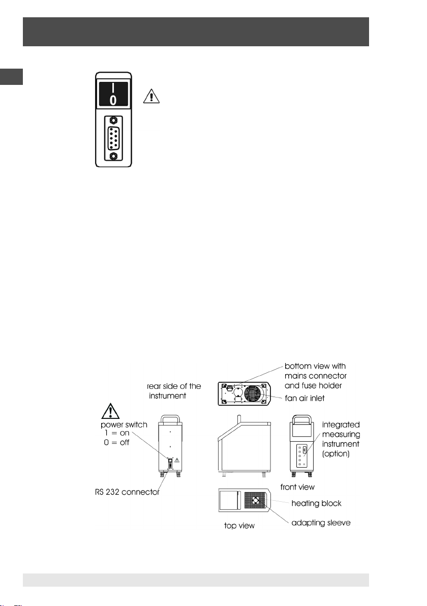
The power socket and the 9-pin Canon socket of the RS 232
interface are on the rear of the device, the power socket and safety
fuse are arranged in the bottom of the device. For this reason, a
power cable with an angled inlet connector must be used.
11WIKA Operating Instructions CTD9300 Rev. 1
Page 12
Temperature Dry Well Calibrators CTD9300
2. Device Description
GB
Fig. 3: Power switch and RS 232 connector
Power switch
The power switch (I/0 toggle switch) on the rear
of the calibrator is used to switch on the power
supply of the calibrator. Switch setting "I"
switches the power supply on, switch setting
"0" switches the power supply off.
Directly to the right of the power switch is a warning symbol.
It means: "Caution, general point of hazard"
RS 232 Connector
Devices that are connected to the RS 232 interface must comply
with the IEC 60950 standard.
The exact location of the power switch can be seen in the
illustration of the mechanical structure in the next section.
Mechanical Structure
Fig. 4: Mechanical structure of a
12 WIKA Operating Instructions CTD9300 Rev. 1
CTD9300
9037926 07/2015
Page 13

Temperature Dry Well Calibrators CTD9300
2. Device Description
2.3 Functional Description
The two devices have identical operating functions, independent of
the different heating principles - Peltier elements in the case of the
165 °C version and resistance heating elements in the case of the
650 °C type.
CTD9300-165 for the range from -30 °C to 165 °C
CTD9300-650 or the range from 40 °C to 650 °C
Both the temperature dry well calibrators are fitted with an
electronic temperature-controlled heating block. This heating block
is fitted with a 28 mm x 150 mm bore for holding the adapting
sleeve.
In this heating block, you can insert adaptor inserts, generally
referred to as adapting sleeves, with one or multiple test bores,
which act as an adapter between the probe (temperature switch,
thermocouple, thermometer or resistance thermometer) and the
heating block bore. The heating block is thermically insulated
against the housing wall.
In the central area of the graphic display (I), the temperature of the
heating block and the set nominal value is displayed with a
resolution of 0.01 K.
The desired heating block temperature is predefined using the
block of 12 keys (G). After confirming the new nominal value with
the ENTER key (E) and switching from measuring to control mode
with the CONTROL key (F), the control unit will start setting the
calibrator to the topical nominal temperature.
In the Info line (K), the displayed mode will change from MEASURE
to CALIBRATE. The operating status HEAT UP, COOL DOWN and
TEMP. STABLE is displayed in the status bar (H).
The temperature is considered STABLE when it changes by less
than 0.1 K within 5 s. Only when the ramp program is enabled does
the STABLE display depend on the set stability criteria tolerance
and duration.
In addition to the topical block temperature, the set nominal value
and the standard deviation or the minimum and maximum values of
the block temperature can be displayed. Using this information, it is
possible to draw a conclusion about the stability of the temperature
in the calibrator at first glance.
GB
9037926 07/2015
13WIKA Operating Instructions CTD9300 Rev. 1
Page 14

Temperature Dry Well Calibrators CTD9300
2. Device Description
GB
Standard deviations as well as the min. and max. values can be
reset at any time by pressing the ENTER (E) key.
2.4 Standard Accessories
Power Cable
A power cable with a 90 ° angled inlet connector for the power
supply is included with every calibrator. Depending on the country
the calibrator is delivered to, the power cable is fitted with the
locally used power plug.
Adapting Sleeve
Each calibrator is delivered ex works with an adapting sleeve with
an inside diameter of 6.5 mm. Most of the industrial thermometers
can be adapted to the calibrator through this sleeve.
If the diameters of your thermometers differ, please order the
desired adapting sleeve with an internal bore matching the diameter
of your thermometer plus 0.5 mm.
Sleeve Removal Tool
A sleeve removal tool for simple and easy removal from and
insertion of the adapting sleeve into the calibrator block is included
in the standard set of accessories of every temperature calibrator of
the CTD9300 series.
Data Cable
A data cable for connecting the calibrator to the RS 232 interface is
included in the scope of delivery of each device. The PIN layout
plan for 9-pin and 25-pin Sub-D connectors can be found in the
Appendix, refer to section 6.6: PC Connection.
2.5 Special Accessories
The special accessories are not included in the standard scope of
delivery.
14 WIKA Operating Instructions CTD9300 Rev. 1
9037926 07/2015
Page 15

Temperature Dry Well Calibrators CTD9300
2. Device Description
2.5.1 Special Adapting Sleeves
Sleeves for CTD9300-165 calibrators are made of aluminium,
sleeves for CTD9300-650 calibrators are made of brass. The
outside dimensions of the two sleeves are Ø 28 mm x 150 mm of
length.
Special adapting sleeves can be customized in various designs.
Sleeves with multiple bores are also available. Limits are placed
only by the mechanical machinability of the sleeve blanks.
When choosing the sleeve design, however, please observe that the
overall measurement uncertainty declines with an increasing
number of bore holes and with increasing bore diameter.
The actual measuring uncertainty when using a special adapting
sleeve can be determined only when the bore diameter and the
number of bores as well as the design and material of the
thermometers to be calibrated is exactly known.
If you require multiple sleeves, please take the following into
consideration:
if possible, the bores should be arranged on a pitch circle to
ensure uniform temperature distribution.
for product engineering reasons, there must be a minimum
distance between the bores and to the edge of the sleeve. As a
rule, this distance should not be less than 2 mm.
the bore diameter should be larger than the thermometer to be
tested by at least 7 %.
GB
9037926 07/2015
2.5.2 Transport Case
As an option, we offer a robust transport case for your calibrator.
We recommend the use of a transport case, if you frequently use
the device for on-site calibrations and thus need to transport it
often.
The case does not only protect your calibrator against environmental influences such as dust, dirt and humidity but also against
mechanical damage that may occur due to impacts and vibrations.
15WIKA Operating Instructions CTD9300 Rev. 1
Page 16

Temperature Dry Well Calibrators CTD9300
2. Device Description
GB
2.5.3 Integratable Measurement Value Logging
In the measurement and control workshop, a measuring instrument
is required for connecting the probe that measures thermovoltages, resistance and 4-20 mA standard signals and displays
them in degrees centigrade.
In combination with the calibrators of the CTD9300 family, the
integratable measuring instrument CTI 9350 is a useful supplement
to your calibration equipment. The measuring instrument can be
integrated in the housing of the CTD9300 calibrators. Order the CTI
9350 directly or upgrade your device later on. We offer you the
choice. In the case of an upgrade, the front panel is simply replaced
in the works.
The temperatures of the two thermometers - of the reference and
the probe - can be displayed at the same time and simply compared
to one another.
The following can be connected as probes:
Resistance thermometers: Pt 100, Pt 500 und Pt 1000 in 2, 3 or
4 wire circuits
Thermocouples of the K, J, N, E, R, T, B, S, L and U types
4-20 mA power signals from temperature transducers, with and
without supply voltage
Temperature switches with "normally open" and "normally
closed" contacts.
The reference resistance thermometer is connected using a 7-pole
connector.
Three different connection possibilities have been provided for the
probe:
Binding posts for 4 mm connectors, spade connectors and
blank wires
Standard thermo-connector
Miniature thermo-connector
The 4 mm sockets (1, 2, 3 and 4) are generally used for connecting
the resistance thermometer, temperature switches and 4-20 mA
signals. All the three connection versions are available for
thermocouples.
16 WIKA Operating Instructions CTD9300 Rev. 1
9037926 07/2015
Page 17

Temperature Dry Well Calibrators CTD9300
2. Device Description
All the thermometer signals are linearised according to their signal
type and displayed in °C, °F or in K.
The sensor type, input and switch technology are set in the menu
for measuring instrument setup.
Circuit of the Integrated Measuring Instrument
Fig. 5: Connectors of the instrument
External Reference Thermometer
The integrated measuring instrument
permits parallel connection of a probe
and, if desired, of an external reference
resistance thermometer. It takes the
characteristic curve of the reference
thermometer into consideration for the
linearisation using an individual
correction function, refer to the
adjustment menu.
An external reference may be required for certain calibration tasks,
e.g.:
when calibrating especially short sensors
for additional safety
GB
9037926 07/2015
2.5.4 Software
Powerful software is available for all devices of the CTD9300
series. This software enables remote control of the calibrator and
the integrated measuring instrument through a computer and
automatic calibrations. The program runs on all IBM compatible
PCs.
Temperature Ramp Function
The temperature ramp function permits the recording of a
temperature curve that automatically approaches up to 20 settable
test points. This is a typical procedure for calibrating electric
thermometers.
17WIKA Operating Instructions CTD9300 Rev. 1
Page 18

Temperature Dry Well Calibrators CTD9300
2. Device Description
GB
When thermometers are calibrated that cannot be read out
electrically, a dialog box for entering the measured value will be
opened. In this case, an integrated instrument is not required.
Fig. 6: Temperature ramp function
Temperature Cycle Function
The temperature cycle function permits the recording of a
temperature curve that automatically switches between two
adjustable set values. In this case, the dwell time of the lower and
upper temperatures as well as the heating and cooling rates can be
set in K/min. The number of temperature changes is preset in the
beginning.
Series of Probes Testing Function
If multiple probes are to be calibrated at the same temperature, e.g.
when testing goods received, the "Check Series of Measurement"
mode must be selected. After the measured values have been
recorded, they can be output as a table and graphically in the form
of a histogram.
18 WIKA Operating Instructions CTD9300 Rev. 1
9037926 07/2015
Page 19

Temperature Dry Well Calibrators CTD9300
2. Device Description
Temperature Switch Testing Function
Recording of the heating and cooling switch points of
temperature switches within an adjustable temperature range.
Fig. 7: Temperature switch test function
GB
9037926 07/2015
Remote Control
This function is used for displaying topical measured values of the
probe and calibrator as well as for programming the temperature
calibrator. It permits a simple check of the communication between
the devices.
Evaluation
Display and printing of the recorded temperature curves in the form
of a table or graphics as well as documentation of the measured
values in the form of a plant calibration certificate. The calibration
data are saved in a database and archived and are thus also
available for evaluations later on.
19WIKA Operating Instructions CTD9300 Rev. 1
Page 20

Temperature Dry Well Calibrators CTD9300
2. Device Description
DGB
System Requirements
IBM-compatible PC with min. 486 processor with Windows 95, 98,
NT 4.0, 9x, ME, 2000 and XP operating system and a main memory
of at least 64 MB, CD-ROM drive or 3 ½" FDD 1,44 MB, VGA
graphics board and monitor, free RS 232 serial interface and
Microsoft-compatible mouse.
2.5.5 DKD Calibration Certificate
The DKD calibration certificate gives the user the certainty that the
calibration results are based on national standards and the errors of
measurement do not exceed the error limits specified.
DKD calibrations are optionally available for all temperature
calibrators. They are an option, the price of which depends on the
number of test points required. For temperature dry well calibrators,
DKD calibrations are generally performed at 6 test temperatures.
The measuring uncertainty specified in the DKD calibration
certificate depends on the device and temperature.
Calibration is a matter of trust. For this reason, entrust only our
competent DKD calibration workshop that has been certified in
compliance with the applicable standard (currently DIN EN ISO/IEC
17025) with the calibration of your valuable devices.
DKD laboratories are subject to periodical inspections by the PTB
(Physikalisch-Technische Bundesanstalt = the German National
laboratory). The laboratory employees are permanently trained and
educated further. Regular inter laboratory comparisons prove that
the minimum measuring uncertainty are really adhered to.
20 WIKA Operating Instructions CTD9300 Rev. 1
9037926 07/2015
Page 21
Temperature Dry Well Calibrators CTD9300
3. Moduses and Functions
3. Moduses and Functions
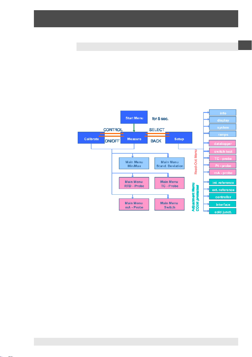
After switching on the calibrator, an information window will be
displayed for approx. 5 s. Then the device switches to measuring
mode. The current block temperature is displayed. The control unit
is switched off.
In the following, the menu structure is displayed in simplified form.
GB
9037926 07/2015
Fig. 8: Menu structure of a
CTD9300
The menu items for datalogger, RTD, TC and mA tests as well as
switch tests are accessible only, if a measuring instrument is
integrated, otherwise they will be hidden.
The two operating modes for measuring and calibrating and the
functions of the Setup menu are described in the following.
21WIKA Operating Instructions CTD9300 Rev. 1
Page 22
Temperature Dry Well Calibrators CTD9300
3. Moduses and Functions
GB
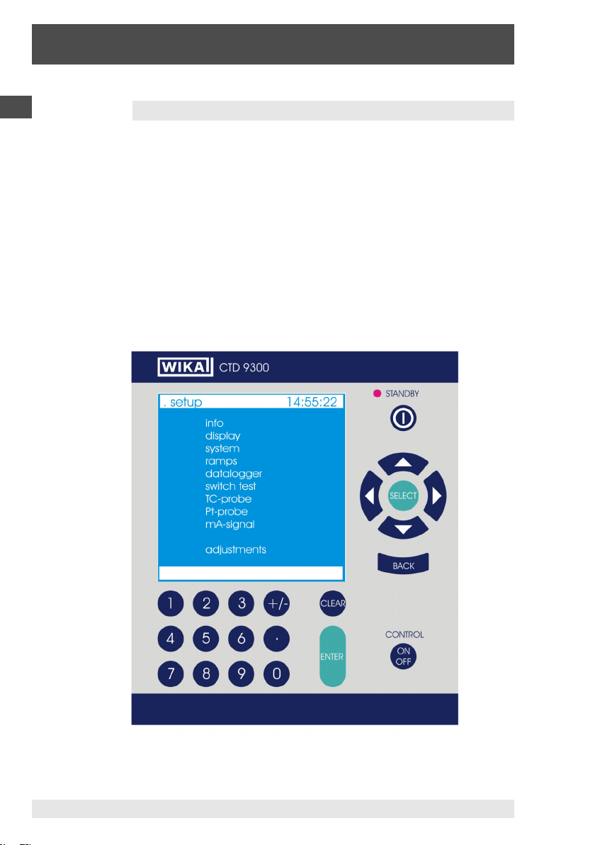
3.1 Setup Menu
Press the SELECT key in the measurement or calibration mode to
access the Setup menu. It is subdivided into:
Basic setup menu
Measuring instrument setup menu
Adjustment setup menu
Select the individual menu items using the cursor keys and the
SELECT key. Press the BACK key to exit the menus.
If you make a selection within a menu, it must be confirmed with
the SELECT key before exiting the menu.
Fig. 9: Setup menu with user interface of a
22 WIKA Operating Instructions CTD9300 Rev. 1
CTD9300
9037926 07/2015
Page 23

Temperature Dry Well Calibrators CTD9300
3. Moduses and Functions
3.1.1 Basic Setup Menu
The basic setup menu is used for typical settings relating to the
general operation of the device, e.g. for calling the Info window that
provides information on the current hardware and firmware
versions or enables editing of the system and display parameters.
The step menu, e.g. can be used to create temperature profiles and
approach them cyclically.
3.1.1.1 Info Menu
The Info menu displays data on the measuring range, the date of
the last calibration, the current firmware ramp and the serial number
of the device.
Depending on the device type, one
of the following measuring ranges
will be displayed:
CTD9300-165 the measuring
range of from -30 °C / 165 °C
CTD9300-650 the measuring
range of from 40 °C / 650 °C
Fig. 10: Info menu of a
CTD9300
GB
9037926 07/2015
The user cannot edit the settings in this window. The firmware
ramps will change accordingly after an update.
The individual serial number of the calibrators is displayed in the
Info menu and additionally on the type label on the rear of the
device.
23WIKA Operating Instructions CTD9300 Rev. 1
Page 24
Temperature Dry Well Calibrators CTD9300
3. Moduses and Functions
GB
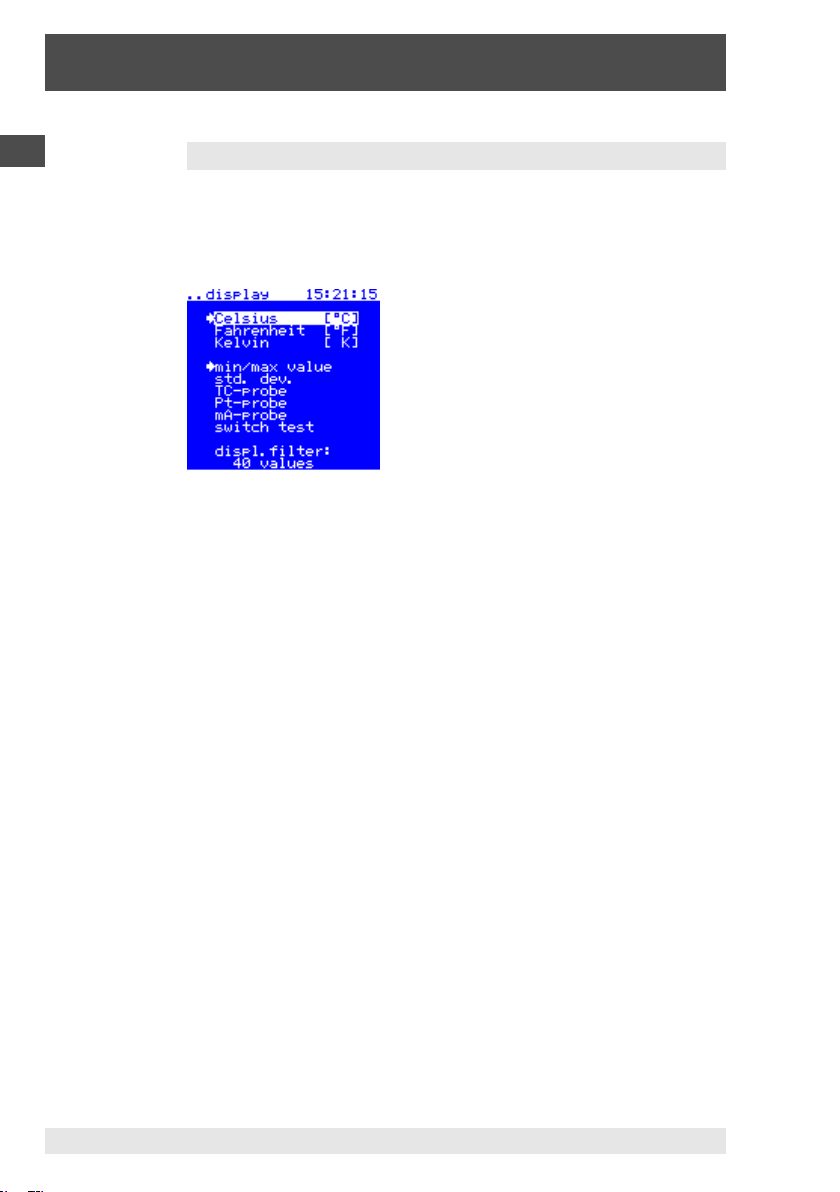
3.1.1.2 Display
The display menu is used for selecting the unit for displaying the
temperature and the desired calibration menu. In addition, the
averaging function of the temperature display can be set.
The desired menu item is
"enabled" using the cursor keys
and selected by pressing the
SELECT key. Selected units and
functions are identified by an
arrow.
Fig. 11: Display adjustment
Unit Selection
You can choose between degrees Celsius °C, degrees Fahrenheit
°F or Kelvin.
Calibration Menu Selections
If a measuring instrument is not integrated, you can choose
between the min./max. value and standard deviation menu items.
If a measuring instrument is integrated, the selection will be
supplemented with:
TC-Probe
Pt-Probe
mA-Probe
switch test
Only one menu can be selected at a time.
Min/max value
Apart from the current block temperature, the minimum and
maximum value of the block temperature will be displayed. Press
ENTER to set min. and max. to the topical measured value.
Using this function, it is easy to assess the maximum limits of
variation of the block temperature in stationary mode.
24 WIKA Operating Instructions CTD9300 Rev. 1
9037926 07/2015
Page 25

Temperature Dry Well Calibrators CTD9300
3. Moduses and Functions
Standard Deviation
Instead of the min./max. value, the standard deviation is displayed
here, i.e. the mean quadratical error of the block temperature across
the last n measured values. After pressing ENTER, n = 0 is set and
the standard deviation will be recalculated.
Switch Test
Test menu for temperature switches, refer to
section 3.1.2 Measuring Instrument Setup Menu.
TC-Probe Menu
Calibration menu for thermocouples, refer to
section 3.1.2 Measuring Instrument Setup Menu.
Pt-Probe Menu
Calibration menu for resistance thermometers, refer to
section 3.1.2 Measuring Instrument Setup Menu.
mA-Probe Menu
Calibration menu for thermometers with temperature transducers,
refer to section 3.1.2 Measuring Instrument Setup Menu.
Display Averaging
The actual value of the block temperature displayed by the device
can correspond to the current temperature or be an average across
2 to 99 measured values. The average is continuously calculated
from the last n measured values according to the FIFO method. A
measuring rate of approx. 4 values/s, the following settings result
for the number of average values:
1, averaging disabled
40, averaging for 10 s
99, averaging for 25 s
GB
9037926 07/2015
To ensure a steady display, we recommend averaging across 50
measured values, which corresponds to an integration time of 13 s.
25WIKA Operating Instructions CTD9300 Rev. 1
Page 26

Temperature Dry Well Calibrators CTD9300
3. Moduses and Functions
GB
3.1.1.3 System
This menu is used for setting the system functions.
Language Selection
In this menu, the user can
select one of the languages
German, English, French or
Spanish using the cursor keys.
The selection must be
confirmed with SELECT.
Fig. 12: System adjustment
Time and Date
The system time and date are selected block by block using the
cursor keys and entered via the numeric keypad. [ hh -> mm -> ss ]
and [ 20yy -> mm -> dd ]. Confirm your entry with ENTER.
Display Settings
Brightness and contrast can be set via the numeric keypad within
the range of from 0 % to 100 %.
Confirm your entry with ENTER.
The following settings are recommended:
Brightness: 80 %
Contrast: 60 % (contrast settings < 50 % are not advisable)
Alarm
When the preselected alarm temperature is exceeded, "temp. to
high" flashes in the information line. The alarm temperature is
entered via the numeric keypad and must be confirmed with
ENTER.
Cut-out
When the preselected switch-off temperature has been exceeded,
the device will automatically be reset to the measuring mode, i.e.
the control unit is switched off. "temp. to high" will flash in the
information line. The device will cool to ambient temperature. The
switch-off temperature is entered via the numeric keypad and must
be confirmed with ENTER.
26 WIKA Operating Instructions CTD9300 Rev. 1
9037926 07/2015
Page 27

Temperature Dry Well Calibrators CTD9300
3. Moduses and Functions
Operating Hours
The operating hours counter continuously counts the time in
hours, for which the device is switched on.
Heat units
The heat units factor is a characteristic value for the thermic load of
the device. It permits conclusions on the average working
temperature of the temperature calibrator. The average working
temperature in °C is calculated as follows by approximation:
t
= t
average
where t
+ ( heat units x 100 / operation hours )
amb.
is the ambient temperature in °C.
amb.
3.1.1.4 Ramp Program
The ramp program with the associated auxiliary parameters is
enabled in the ramp menu. It is used, e.g. for checking recording
temperature measuring instruments.
Another field of application is
the temperature change test,
which makes it possible to draw
conclusions on the
reproducibility, the hysteresis
and the long-term and shortterm stability of temperature
sensors.
Fig. 13: Ramp menu
GB
9037926 07/2015
If a measuring instrument is integrated in the calibrator, the
measured values of the probes can be recorded at the selected
temperature ramps. Please also refer to the section DataLogger in
Chapter Measuring Instrument Setup Menu.
Temperature Ramp Function
The temperature ramp program is switched on by selecting the UP
and/or DOWN function with the cursor. The default setting is OFF.
In the ramp program, 6 different temperature ramps can be enabled
individually or together. For this purpose, the ramps are selected
with the cursor and enabled/disabled with the SELECT key. Every
single temperature ramp can be set to any desired temperature
27WIKA Operating Instructions CTD9300 Rev. 1
Page 28

Temperature Dry Well Calibrators CTD9300
3. Moduses and Functions
GB
within the operating range of the calibrator.
The resolution is 0.01 K.
The individual temperature ramps are serially numbered from 1 to 6.
If the "UP" function is enabled, the ramps are approached in the
order 1, 2, 3, 4, 5 and 6. If the "DOWN" function is enabled, the
ramps are approached in the order 6, 5, 4, 3, 2 and 1. If both
functions are enabled, the ramps are approached in the order 1, 2,
3, 4, 5, 6, 5, 4, 3, 2 and 1. Disabled ramps are skipped.
Gradient
Using the gradient function, defined heating and cooling of the
calibrator can be set. The value for the gradient is set in K/min with
a resolution of 1 K.
The upper ramp for the gradient is determined through the heating
power of the respective device. This means that the device with the
gradient function enabled cannot heat at a faster rate than with the
gradient function disabled. The gradient function is primarily used
for checking temperature switches. To prevent the switch point of a
temperature switch from being exceeded during heat-up, the
calibrator is heated only slowly. Gradients between 1 K/min and
5 K/min are typical. Especially for temperature switches with large
immersion tube diameters, this prevents that the temperature of the
switch lags behind that of the calibrator.
Tolerance and Duration
Using the Tolerance and Duration functions, the stability and
length of the dwell time on a temperature ramp can be set. If the
dwell time is to be 5 minutes with a stability of ±0.1 K after the
nominal temperature has been reached, the duration must be set to
5 min and the tolerance to 0.1 K. In this case, the timer will start
when the actual temperature differs by less than 0.1 K from the
nominal temperature. If the temperature remains within this
tolerance for 5 min, the time period for the next ramp will be
approached after the present time period has elapsed. If
fluctuations occur during this time that exceed the set tolerance,
the timer is reset and restarted. When the tolerance has been
reached, TEMP. STABLE is displayed in the status bar.
28 WIKA Operating Instructions CTD9300 Rev. 1
9037926 07/2015
Page 29

Temperature Dry Well Calibrators CTD9300
3. Moduses and Functions
The tolerance can be set within the limits of 0.01 K and 5.00 K,
the duration within the range of from 1 min to 100 min.
Cycles
Using the Cycles function, the calibrator can approach the ramps
continuously. If e.g. the temperature ramps 1, 2 and 3 are enabled
and the "UP" function has been selected, the ramps 1, 2 and 3 are
approached one after the other depending on the set cycles: with a
number of cycles of 3 this would be 1, 2, 3, 1, 2, 3, 1, 2 and 3.
If the "UP" and "DOWN" functions have been selected, the
calibrator will proceed as follows: 1, 2, 3, 2, 1, 2, 3, 2, 1, 2, 3, 2
and 1.
This function is especially useful for temperature change tests on
temperature sensors.
If the ramp program is enabled, set-values cannot be entered
via the keyboard. The keyboard will remain locked until the
temperature ramp function is disabled.
3.1.2 Measuring Instrument Setup Menu
The measuring instrument setup menu is available only if the
calibrator is equipped with an integrated measuring instrument.
The menu is used for configuring the data logger and the
calibration processes of temperature switches, thermocouples,
resistance thermometers and 4-20 mA temperature transmitters.
The menu is hidden if the calibrator is not equipped with an
integrated measuring instrument.
The integrated measuring instrument makes it possible to measure
various sensor signals and to convert them to degrees Centigrade
according to standardised characteristic curves. It is also possible
to detect switch points of temperature switches. The data logging
function permits storing as many as six probe temperatures and the
nominal temperature per probe given by the calibrator. In total, the
calibration data of up to eight probes can be recorded.
GB
9037926 07/2015
29WIKA Operating Instructions CTD9300 Rev. 1
Page 30

Temperature Dry Well Calibrators CTD9300
3. Moduses and Functions
GB
The following devices are supported:
Pt resistance thermometers with characteristic curves in
compliance with EN 60751
Thermocouples in compliance with EN 60584 and DIN 43710
2-wire temperature transducer with an output signal of
4-20 mA
Temperature switches with "normally closed" or "normally open"
contacts.
3.1.2.1 Data Logger
This menu is used for configuring the data logger. The data logger
permits the storage of calibration results of up to eight calibrations.
In this case, a calibration can include up to six testing
temperatures. A prerequisite is that the ramp program is enabled
and the desired testing temperatures have been set in advance in
this program.
The last cycle is always stored,
independent of whether the
levels were approached from
bottom to top or vice versa. For
this reason, it is best to set the
number of cycles to 1 when
recording measured values.
Fig. 14: "Data Logger"
setup menu
When the data logger is disabled, sets, i.e. the measured value
storages can be selected via the cursor keys. It is possible to select
Set1 to Set8.
One set may hold up to 6 measuring results. If e.g. only four
measurements are made, the remaining two rows of the value table
remain empty.
When the data logger is switched on, the measuring results are
stored in the current set. It is not possible to change the set when
the data logger is enabled.
30 WIKA Operating Instructions CTD9300 Rev. 1
9037926 07/2015
Page 31

Temperature Dry Well Calibrators CTD9300
3. Moduses and Functions
Date and Start time document the beginning of the recording.
Probe specifies the type of thermometer to be calibrated.
TC-Probe
Pt-Probe
mA-Probe
Menu item CL (Clear Logger) is
used to clear the stored
contents of the enabled set. If a
new calibration is started
without deleting the old data,
these data will be overwritten
with the new data.
Fig. 15: Recorded calibration
data
Procedure when using the data logging function:
Select ramp program in the Setup menu:
Select UP or DOWN with the cursor keys.
Change the desired temperature ramps
Set the tolerance to the desired value, e.g. 0.05 K
Set the duration to the desired value, e.g. 2 min
Set the cycles to 1
Select BACK to exit the ramp program:
GB
9037926 07/2015
Select Data Logger in the Setup menu:
Select the desired Set(n), n= 1, 2, ..., 8 with the cursor keys
If required, delete any calibration data stored in the respective
set with CL
Select ON with the cursor keys and enable the logging function
Select BACK to exit the Data Logger
Press BACK again to return to the main menu (Calibrate).
31WIKA Operating Instructions CTD9300 Rev. 1
Page 32

Temperature Dry Well Calibrators CTD9300
3. Moduses and Functions
GB
During the program run, you can toggle between the main menu
and the data logging menu to display temperature levels already
processed.
Once the program run of the logging program has been completed,
the ramp program and the data logger are automatically set to OFF.
The calibration data recorded can either be displayed in the data
logging menu or downloaded via the RS 232 interface.
3.1.2.2 Switch Test
This menu is used for configuring the temperature switch test. It is
possible to determine switch points and the hysteresis of a
temperature switch.
The switch test program and
the temperature ramp program
are automatic program runs
that exclude one another. When
the program is enabled, all the
functions not used for testing
temperature switches are
disabled.
Fig. 16: Switch test setup
menu
The switch test is started by pressing ENTER and can be aborted at
any time with CONTROL ON/OFF. An interrupted switch test is
identified with the status bar message SWITCH TEST. HEAT UP or
COOL DOWN will be displayed in the status bar during the switch
test.
Rem. temp, T
max
or T
are displayed to the left-hand side of the set
min
temperature. After the test has been completed and the hysteresis
has been calculated, the removal temperature will be controlled
such that a new switch test can be started. If the temperature
fluctuations are < 0.1 K, TEMP.STABLE will be displayed in the
status bar.
32 WIKA Operating Instructions CTD9300 Rev. 1
9037926 07/2015
Page 33

Temperature Dry Well Calibrators CTD9300
3. Moduses and Functions
Checking Temperature Switches
The approximate switch point
should be known for testing
temperature switches. In the
Setup, below the switch point
to be expected, a removal
temperature will be set at
which the probe can be
removed without risk.
Fig. 17: Switch test diagram
A lower and an upper limit temperature, UGT (lower limit temp.) and
OGT (upper limit temp.) are defined approx. 5 K above and below
the switch point.
At program start, the calibrator will control the temperature to the
removal temperature. After ENTER was pressed, the calibrator will
heat up to the lower limit temperature (UGT) with full heating
power. From there on, it will maximally heat to the upper limit
temperature (OGT) with the set gradient. If there is no switching
between the lower limit temperature (UGT) and the upper limit
temperature (OGT), the device will heat to the predefined removal
temperature.
If the device switches as expected between the lower (UGT) and
upper (OGT) limit temperatures, the switch temperature is displayed
as "t-up". The calibrator immediately starts to cool to record the
second switch point "t-down" in downward direction. Thereafter,
the removal temperature is controlled. The hysteresis is the
difference between the "t-up" and "t-down" temperatures.
GB
9037926 07/2015
Defective Temperature Switches
If the temperature switch does not switch within the selected range,
the calibrator will maximally heat to the upper limit temperature
(OGT) and then cool to removal temperature.
33WIKA Operating Instructions CTD9300 Rev. 1
Page 34

Temperature Dry Well Calibrators CTD9300
3. Moduses and Functions
GB
3.1.2.3 TC-Probe
This menu is used for configuring the thermocouple calibration.
To calibrate thermocouples, the
respective type of
thermocouple is selected with
the cursor keys and confirmed
with the SELECT key.
Subsequently, the input
sockets must be defined.
Fig. 18: TC-probe setup
menu
There are two possibilities:
binding posts 2 and 3
-> input 2
Thermo-socket TC
-> input 3
Fig. 19: Connectors of the
instrument
Binding Posts
The binding posts are suitable for connecting blank wire ends,
spade connectors and 4 mm banana plugs.
Thermo-Socket
The thermo-socket can be used to connect standard thermoconnectors and miniature thermo-connectors.
Always observe the correct polarity when connecting thermocouples. If thermocouples need to be extended, the thermo-cable
or extension cable of the respective thermocouple type must be
used.
34 WIKA Operating Instructions CTD9300 Rev. 1
9037926 07/2015
Page 35

Temperature Dry Well Calibrators CTD9300
3. Moduses and Functions
3.1.2.4 Pt-Probe
This menu is used for configuring the Pt resistance thermometer
calibration.
To calibrate Pt resistance
thermometers, the respective
type of thermometer and
connection is selected with the
cursor keys and confirmed with
the SELECT key. The
connection is established
exclusively via the binding
Fig. 20: Pt-probe
setup menu
posts.
Binding posts
The binding posts are suitable for connecting blank wire ends,
spade connectors lugs and 4 mm banana plugs. Take the required
wiring technology into consideration for establishing connections.
There are three possibilities:
2-wires: terminals 2 + 3
3-wires: Terminals 3 + 4 loop, 2 + 3 Pt resistance
4-wires: Terminals 1 + 2/3 + 4 loop, 2 + 3 Pt resistance
Interchanging the connectors results in measurement faults.
GB
9037926 07/2015
35WIKA Operating Instructions CTD9300 Rev. 1
Page 36

Temperature Dry Well Calibrators CTD9300
3. Moduses and Functions
GB
3.1.2.5 mA-Probe
This menu is used for configuring the temperature transducer
calibration.
Setting the Current Range
If the probe is a 2-wire
transducer, the current range
must be set to 4-20 mA, for
3-wire transducers that are
generally supplied with
operating voltage externally, a
range of 0-20 mA can be set.
Fig. 21: mA-probe
setup menu
Setting the Temperature Range
To be able to convert the output current of the transducer properly
to a temperature signal, the measuring instrument must know the
limit temperatures for 4 mA (0 mA) and 20 mA. They must be
entered according to the specifications at the transducer.
Setting the Supply
Prior to a transducer calibration you must define whether the
calibrator is to supply the transducer with 24 V DC operating
voltage or not. Generally, this is the case. If it is supplied through
an external voltage source, the internal supply must be switched
off.
36 WIKA Operating Instructions CTD9300 Rev. 1
9037926 07/2015
Page 37

Temperature Dry Well Calibrators CTD9300
3. Moduses and Functions
3.1.3 Adjustment Setup Menu
The Adjustment setup menu is password-protected. The menu
provides setting options for control parameters, linearisation
parameters for internal and external reference sensors and the
interface parameters. These settings are made ex works and
generally need not be edited by the user.
The "int. reference" and "ext. reference" menus specify the
coefficients for linearising the reference thermometer of the
calibrator. If errors of
measurement larger than
those specified are detected
when calibrating the device,
the coefficients can be edited
in this menu for adjustment
purposes.
Fig. 22: Adjustment setup
menu
In the same way, the control parameters and settings of the serial
interface can be edited.
Caution!
Editing the parameters in the Adjustment setup menu may
result in serious errors of the temperature display and to
changed control characteristics!
Entering wrong parameters may cause irreversible damage to
the dry well calibrator!
GB
9037926 07/2015
The Cold junction menu item permits enabling/disabling the cold
junction compensation for testing purposes.
37WIKA Operating Instructions CTD9300 Rev. 1
Page 38

Temperature Dry Well Calibrators CTD9300
3. Moduses and Functions
GB
3.1.3.1 Internal Reference
This menu comprises the parameters for linearising the internal
reference thermometer.
The internal reference
thermometer is linearised in two
stages. First of all, using a basic
linearisation that is always
performed and thereafter using
an individual fine linearisation.
In this case, "t'" is the
temperature following the basic
Fig. 23: Internal reference
parameter set
linearisation.
t display = P0 + P1 * t' + P2 * t' ² + P3 * t' ³ + P4 * t' 4
Linearisation CTD9300-650 CTD9300-165
parameters
P0 0 0
P1 1 1
P2 0 0
P3 0 0
P4 0 0
Using these parameters, only the general basic linearisation is
enabled and fine linearisation is switched off. In the case of DKD
calibration of the temperature calibrators, the errors of
measurement of the reference are exactly determined and the
parameters P0 to P4 are set to the optimum.
Fine linearisation can be disabled by setting the switch to OFF.
This function simplifies the determination of new parameters Pn
for adjusting the reference, at an autuorised laboatory.
The user should not edit these settings.
38 WIKA Operating Instructions CTD9300 Rev. 1
9037926 07/2015
Page 39

Temperature Dry Well Calibrators CTD9300
3. Moduses and Functions
3.1.3.2 External Reference
This menu comprises the parameters for linearising the external
reference thermometer.
The external reference
thermometer is also linearised
in two stages. First of all, using
a basic linearisation that is
always performed and
thereafter using an individual
fine linearisation. In this case,
"t'" is the temperature following
Fig. 24: External reference
parameter set
the basic linearisation.
t display = P0 + P1 * t' + P2 * t' ² + P3 * t' ³ + P4 * t' 4.
Linearisation CTD9300-650 CTD9300-165
parameters
P0 0 0
P1 1 1
P2 0 0
P3 0 0
P4 0 0
GB
9037926 07/2015
Using these parameters, only the general basic linearisation is
enabled and fine linearisation is switched off. In the case of DKD
calibration of the temperature calibrators, the errors of
measurement of the reference are exactly determined and the
parameters P0 to P4 are set to the optimum.
Fine linearisation can be disabled by setting the switch to OFF.
This function simplifies the determination of new parameters Pn
for adjusting the reference, at an autuorised laboatory.
The user should not edit these settings.
39WIKA Operating Instructions CTD9300 Rev. 1
Page 40

Temperature Dry Well Calibrators CTD9300
3. Moduses and Functions
GB
3.1.3.3 Controler
This menu is used to set the control parameters.
Fig. 25: Control parameter set
The parameter set in the basic configuration is as follows (devicedependent):
Control parameter CTD9300-650
P0 1.00000E+00
P1 1.00000E-03
P2 1.00000E+00
P3 0.00000E+00
P4 1.00000E-01
CTD9300-165
1.00000E+00
1.00000E-02
1.00000E+00
0.00000E+00
1.00000E-01
Where:
Control parameter Designation
P0 internal amplification
P1 adjustment of the disturbance variable
P2 time constant
P3 test parameter
P4 safety limit of the dynamic
Warning!
Ex works, the control parameters are set for an optimum
control behaviour.
The user should not edit these settings.
40 WIKA Operating Instructions CTD9300 Rev. 1
9037926 07/2015
Page 41

Temperature Dry Well Calibrators CTD9300
3. Moduses and Functions
3.1.3.4 Interface
The Interface menu is used to set the baud rate for data
transmission via the RS 232 interface and the protocol to be used.
Baud rate
2400 Baud, 4800 Baud and
9600 Baud are supported. They
are selected with the cursor
keys and enabled with the
SELECT key.
Fig. 26: Interface parameters
Protocol
The default setting is the standard protocol, which must always be
set when the calibrators are operated in combination with our
software. The following settings are possible:
Standard: standard protocol
Test: in-plant test protocol
Display: in-plant test protocol
The protocols are selected with the cursor keys and enabled with
the SELECT key.
GB
9037926 07/2015
Parity
For setting the parity. Default setting is "no". Other possible
settings are "even" and "odd".
41WIKA Operating Instructions CTD9300 Rev. 1
Page 42

Temperature Dry Well Calibrators CTD9300
3. Moduses and Functions
GB
3.1.3.5 Cold Junction
In the Cold Junction menu, the internal cold junction
compensation can be disabled. The internal cold junction
compensation is normally
disabled for service purposes
only.
The user should not change
these settings, except when an
external cold junction
compensation is used.
Fig. 27: Cold Junction menu
42 WIKA Operating Instructions CTD9300 Rev. 1
9037926 07/2015
Page 43

Temperature Dry Well Calibrators CTD9300
3. Moduses and Functions
3.2 Measuring Mode
Press the CONTROL key to switch between the measuring and
calibration mode. As opposed to calibration mode, the control unit
is switched off in measuring mode.
"Measure" is displayed in the
top left-hand side of the status
bar. The fan cools the calibrator.
If a new nominal value is not
defined, the calibrator will reach
ambient temperature sooner or
later, depending on the
previous application
Fig. 28: Main menu,
measuring mode
temperature.
Measuring mode is active after:
switching on the device
activating the temperature cut-out
a fault occurred
Apart from the current block temperature, the standard deviation
across the last n measured values (n = 1 ... 99) as well as the
gradient, the temperature change per minute, is displayed.
GB
9037926 07/2015
If an external reference thermometer is connected, the selection
"t- intern" and "t-extern" will be displayed underneath the nominal
value display. This permits the user to select between an internal
and external reference thermometer. The external reference
thermometer takes on all the functions of the internal thermometer.
Generally, it is used for calibrating very short thermometers only.
43WIKA Operating Instructions CTD9300 Rev. 1
Page 44

Temperature Dry Well Calibrators CTD9300
3. Moduses and Functions
GB
3.3 Calibration Mode
Press the CONTROL key to switch between the measurement and
calibration mode. The control unit is active in calibration mode.
"Calibrate" will be displayed in the top left-hand side of the status
bar.
The standard menu can always
be accessed, independent of
whether an integrated
measuring instrument is
integrated or not.
The following generally applies:
In calibration mode and in
measuring mode, the current
Fig. 29: Main menu,
calibration mode
block temperature and the
nominal temperature last
selected are displayed independent of the selected menu.
In addition, the gradient is specified in K/min in the last menu line.
The gradient permits conclusions on the current temperature
change rate.
If an integrated measuring instrument is available, additional
connection possibilities and menus. These are described in the
section on the measuring menu.
The current status is displayed in the info line. Heating, cooling or
stable. Depending on the availability of an integrated measuring
instrument, the following calibration and display modes are
available.
Prompting in a set-value
You can define a new set-value using the block of 12 keys. After
confirming your entry with the ENTER key, the controller will save
the value. Now press the CONTROL key once to start the control
unit. In the Info line, the mode will change from measuring to
calibration. In parallel, the operating status of the control unit is
displayed in the status line:
heating when the temperature in the block is increased
44 WIKA Operating Instructions CTD9300 Rev. 1
9037926 07/2015
Page 45

Temperature Dry Well Calibrators CTD9300
3. Moduses and Functions
cooling when the block is cooled
temp. stable when a constant temperature has set in the block.
Selection between Internal and External Reference
Thermometer
If an external reference thermometer is connected, the selection
"t- intern" and "t-extern" will be displayed underneath the nominal
value display. This permits the user to select between an internal
and external reference thermometer. The external reference
thermometer takes on all the functions of the internal thermometer.
Generally, it is used for calibrating extremely short thermometers
only.
3.3.1 Standard Menus
In the standard menu, the following values can be displayed on the
calibrator without an integrated measuring instrument.
Min/Max value
Standard Deviation
When the ramp program menu
is enabled, the current
temperature ramps 1 to 6 are
displayed in the calibration and
measuring modes instead of
the set temperature.
GB
9037926 07/2015
Fig. 30: Calibration menu
"Data Logger"
45WIKA Operating Instructions CTD9300 Rev. 1
Page 46

Temperature Dry Well Calibrators CTD9300
3. Moduses and Functions
GB
3.3.1.1 Calibration Menu “min/max”
In addition to the temperature
display, the min. and max.
values of the current block
temperature are displayed. The
two values are displayed
continuously. The registration of
the min. and max. values is
restarted with the ENTER key.
Fig. 31: Calibration menu
“min/max”
The variation limits of the
temperature in the calibrator can
easily be displayed through the
min. and max. temperatures.
3.3.1.2 Calibration Menu “sta. dev.”
In addition to the temperature
display, the standard deviation
of the current block temperature
is continuously displayed. The
recalculation of the standard
deviation is restarted with the
ENTER key.
The stability of the temperature
Fig. 32: Calibration menu
“standard deviation”
in the calibrator can easily be
displayed through the standard
deviation.
46 WIKA Operating Instructions CTD9300 Rev. 1
9037926 07/2015
Page 47

Temperature Dry Well Calibrators CTD9300
3. Moduses and Functions
3.3.2 Measuring Instrument Menus
If the calibrator is equipped with an integrated measuring
instrument, a measuring instrument menu is available in addition to
the standard menu. This comprises the following functions:
Temperature switch test
Thermocouple calibration
Pt resistance thermometer calibration
4-20 mA transducer calibration
The selection of external and internal reference thermometer is
provided only, if an external reference thermometer is connected.
The deviation of the probe is either specified in comparison to the
internal or external reference, depending on which of the two
references is enabled.
If the "Ramp Program" menu or
the "Data Logger" function is
enabled, the current
temperature ramps 1 to 6 will
be displayed in the calibration
and measuring modes instead
of the set temperature.
Fig. 33: Calibration menu
"Data Logger"
GB
9037926 07/2015
3.3.2.1 Calibration Menu “Switch Test”
In this menu, the switching
temperatures can be displayed
in addition to the nominal and
actual temperatures of the
calibrator.
Fig. 34: Calibration menu
"switch test"
47WIKA Operating Instructions CTD9300 Rev. 1
Page 48

Temperature Dry Well Calibrators CTD9300
3. Moduses and Functions
GB
The following information is provided:
Designation
Probe
t-open
t-close
Hysteresis
Information
Type of probe
opening temperature
of the switch
closing temperature
of the switch
The difference between
"t-open" and "t-close"
3.3.2.2 Calibration Menu “TC-Probe”
In this menu, the output signal
of a thermocouple can be
displayed in addition to the
nominal and actual
temperatures of the calibrator.
Fig. 35: Calibration menu
“TC-probe”
Note
Temperature switch
in this example: 107.32 °C
in this example: 103.98 °C
in this case: 3.34 K
The following information is provided:
Designation
Probe
t-Probe
Error
Signal
48 WIKA Operating Instructions CTD9300 Rev. 1
Information
Type of probe
Temperature of the
probe
Error of the probe
in K
Electric output signal
of the probe
Note
Thermocouple: TCJ-3, i.e.
Thermocouple J at input 3
in this example: 102.67 °C
Deviation from the int. (ext.)
reference thermometer
In the case of the thermocouple,
the thermal voltage in µV
9037926 07/2015
Page 49

Temperature Dry Well Calibrators CTD9300
3. Moduses and Functions
3.3.2.3 Calibration Menu “Pt-Probe”
In this menu, the output signal
of a Pt resistance thermometer
can be displayed in addition to
the nominal and actual
temperatures of the calibrator.
Fig. 36: Calibration menu
“Pt-probe”
The following information is provided:
Designation
Probe
t-Probe
Error
Signal
Information
Type of probe
Temperature of the
probe
Error of the probe
in K
Electric output signal
of the probe
GB
Note
Pt resistance thermometer:
Pt 100-3, i.e.
Pt 100 in 3-wire circuits
in this example: 102.99 °C
Deviation from the int. (ext.)
reference thermometer
In the case of the Pt resistance
thermometer, the resistance in
Ohm
9037926 07/2015
49WIKA Operating Instructions CTD9300 Rev. 1
Page 50

Temperature Dry Well Calibrators CTD9300
3. Moduses and Functions
GB
3.3.2.3 Calibration Menu “mA-Probe”
In this menu, the output signal
of an electric thermometer can
be displayed in addition to the
nominal and actual
temperatures of the calibrator.
Fig. 37: Calibration menu
“mA-probe”
The following information is provided:
Designation
Probe
t-Probe
Error
Signal
Information
Type of probe
Temperature of the
probe
Error of the probe
in K
Electric output signal
of the probe
Note
Transducer
in this example: 99.94 °C
Deviation from the int. (ext.)
reference thermometer
In the case of the transducer,
the current in mA
50 WIKA Operating Instructions CTD9300 Rev. 1
9037926 07/2015
Page 51

Temperature Dry Well Calibrators CTD9300
4. Operating the Calibrator
4. Operating the Calibrator
4.1 Setup and Connection
Connect the power cable supplied to the calibrator and plug the
power connector into the mains socket. Set up the calibrator such
that the fan on the bottom of the device has sufficient free space to
be able to circulate a sufficient cooling air rate. Insufficient venting
may cause damage leading to the destruction of the calibrator.
Set up the calibrator such that the power switch (switch for power
supply) is easily accessible and can be actuated without any
problems.
Caution!
Since the housing of the calibrator is made of metal, only power
cables with ground wire may be used. Use the power cable
supplied.
Caution!
Ensure that all the bores of the heating block are clean and free
of damage. Do not use any filling media.
Place the calibrator in an upright position for the calibration
procedure to ensure optimum temperature distribution and
transmission.
GB
9037926 07/2015
Additionally take the following into consideration:
the probe
the adapting sleeve and
the bore of the heating block
must exactly match.
Keep the thermal contact resistance as low as possible by using
adapting sleeves with test bores, the inside diameters of which are
approx. 0.2 mm to max. 0.5 mm larger than the diameter of the
probe.
51WIKA Operating Instructions CTD9300 Rev. 1
Page 52

Temperature Dry Well Calibrators CTD9300
4. Operating the Calibrator
GB
Connect the device to a power circuit with minimum risk of a power
failure, since it will no longer be possible to supply cooling air in
the case of a power failure.
4.2 Starting Procedure
If the calibrator is not used for an extended period of time, a small
amount of humidity may collect due to the hygroscopic
characteristic of the magnesium oxide used as insulating material
in the heating system.
After transporting or storing the device in a humid environment,the
heating elements must thus be heated slowly when starting the
calibrator. During the drying process, the device will not have
attained the isolation voltage required for protection class I.
The nominal startup value is T
t
= 15 min.
h
= 120 °C at a dwell time of
anf
4.3 Initial Use
Checks prior to initial use
Prior to initial use, the devices must be moved to their standard
upright operating position. When installing the device, make sure
that the fan on the bottom can circulate a sufficient rate of air. Do
not use soft, resilient surfaces.
Remove all highly combustible material from the vicinity of the
device and ensure that the device cannot come into contact with
easily inflammable or explosive media.
Proceed as follows:
Check the technical data specified on the type label.
Always place the CTD9300 in an upright position. Otherwise
uniform temperature distribution in the block cannot be
ensured.
Do not use any filling media.
52 WIKA Operating Instructions CTD9300 Rev. 1
9037926 07/2015
Page 53

Temperature Dry Well Calibrators CTD9300
4. Operating the Calibrator
Check and ensure the following:
The calibrator must be complete. An adapting sleeve with an
inside diameter of 6.5 mm, appropriate for probes with a
diameter of 6 mm, a sleeve removal tool, a power cable, an
RS 232 interface cable and operating instructions are standard
accessories.
The probe and the adapting sleeve as well as the bore of the
block must match exactly to keep the thermal contact resistance
as low as possible.
The mains voltage must match the supply voltage specified on
the type label.
The device must be connected to a power circuit with minimum
risk of a power failure, since it will no longer be possible to
supply cooling air in the case of a power failure.
All the bores of the adapting sleeve must be clean and free of
damage and foreign matters.
After activation via the power switch and switchover from
standby to standard operation, the fan must start when button
(B) is pressed.
4.4 Cooling of the Block and Replacing the Sleeve
Calibrators with a hot dry well always bear an imminent hazard of
burns.
GB
9037926 07/2015
Risk of burns!
Depending on the type, the dry well of a calibrator may reach
temperatures of up to 650 °C.
Let the calibrator cool after use. Only transport the calibrator after it
has cooled completely. The dry well temperature should be below
30 °C.
When touching the surface of the heating block, the adapting
sleeve or the probe, or even when approaching them, there may be
an imminent hazard of burns. Never touch these surfaces if you are
not absolutely sure that these parts are cold.
53WIKA Operating Instructions CTD9300 Rev. 1
Page 54

Temperature Dry Well Calibrators CTD9300
4. Operating the Calibrator
GB
Never leave the temperature calibrator unattended during or after
use. Wait until the heating block has reached room temperature, i.e.
25 °C before packaging it.
You can accelerate the cooling process by setting the testing
temperature to the smallest value possible.
Also take care when replacing the adapting sleeves!
Risk of burns!
The adapting sleeves may reach temperatures of up to 650 °C.
Remove the inserts only when they have cooled.
Use a sleeve removal tool for removing the adapting sleeve, press it
together and insert it into the bores provided on the adapting
sleeve.
Then cautiously pull the sleeve straight up out of the block without
canting it.
Place the sleeve on a solid, temperature resistant surface.
Do not let the adapting sleeve inserts fall. The edges may be
damaged which may lead to jamming of the sleeve when sliding it
back in the block.
4.5 Application Examples
Type CTD9300-165 for the range of from - 30 °C to 165 °C
In the bio-pharmaceutical and food industry as well as in the field
of heating, air conditioning and ventilation, temperatures between
0 °C and 100 °C are often measured. With its fast Peltier elements,
each temperature can be attained within a few minutes. The
aluminium block accommodates adapting sleeves of the
dimensions Ø 28 mm x 150 mm. It can even be used to calibrate
multiple typical thermometers at the same time.
Type CTD9300-650 for the range of from 40 °C to 650 °C
In the technical service and measurement and control workshop,
temperature dry well calibrators are used for calibrating electric
thermometers and for adjusting temperature transducers. With its
54 WIKA Operating Instructions CTD9300 Rev. 1
9037926 07/2015
Page 55

Temperature Dry Well Calibrators CTD9300
4. Operating the Calibrator
large temperature range of from 40 °C to 650 °C, the CTD9300650 is a universally applicable allround calibrator that can be
adapted to various calibration requirements.
Irrespective of whether transducers are to be adjusted or
temperature sensors are to be calibrated on test benches, the
CTD9300650 has been proven and tested in numerous calibration
tasks, in the laboratory, in the workshop and on site.
Calibrating Thermometers < 150 mm
If probes cannot be inserted down to the bottom of the adapting
sleeve due to insufficient sheath length, the heat dissipation error
produced can be considerably reduced by using an external
reference thermometer. For this purpose, an adapting sleeve with
two test bores is used.
The probe and the reference thermometer are inserted to the same
depth in the adapting sleeve. After switching to "t-extern", the
external reference thermometer will take on the measuring and
control tasks.
The minimum insertion depth of probe and reference should not
drop below 70 mm since the control system changes and the
stability gets worse when the reference thermometer is not
immersed deep enough. In addition, it will take longer until a stable
temperature is attained.
If probes are inserted to a depth less than 150 mm, the uncertainty
of measurement will increase during calibration. It is not possible to
make a general statement in this case, since with a low immersion
depth, factors such as:
Sheath diameter
Heat conductivity of the sheath material
Sensitive sensor length
Ambient temperature
considerably affect the uncertainty of measurement.
If short probes are to be calibrated frequently using the CTD9300,
this fact can be considered individually on customer request when
adjusting and calibrating the CTD9300, even in the measurement
uncertainty budget.
GB
9037926 07/2015
55WIKA Operating Instructions CTD9300 Rev. 1
Page 56

Temperature Dry Well Calibrators CTD9300
4. Operating the Calibrator
GB
4.6 Troubleshooting
Replacing the Fuses
The calibrators are equipped with a safety fuse. They are located on
the bottom of the calibrator, integrated in the power connection. If
the fan does not start of the display remains dark, check the fuse
and replace it, if it has blown. Replace defective fuses only with
fuses with the ratings specified in the present manual.
CTD 9360-650 CTD 9360-650CTD9300-165
100 ... 230 VAC 230 VAC 115 VAC
T6.3A 250V T6.3A 250V T10A 250V
If a replaced fuse blows repeatedly, the device is probably defective.
In this case, send the device to the manufacturer for repair.
In view of any warranty claims and your own safety, do not perform
repairs yourself.
Never open the housing!
The housing does not accommodate any components that can
be serviced by the user.
Fault - What Can You Do?
Fault
Calibrator does not
work properly
Calibrator is working but
heater dos not work
Cause
External influences, e.g.
magnetic fields,
incorrect supply voltage
Ground wire monitor
active
Corrective action
Check the applied mains
voltage against the
supply voltage specified
on the type label.
Pull the power cable,
check the fuse and
replace it if defective.
Check the ground wire
connection of the
calibrator.
Re-establish the
connection to the
ground wire system
If the device is still not working properly after you have checked the
above items, it must be checked at the manufacturer's.
56 WIKA Operating Instructions CTD9300 Rev. 1
9037926 07/2015
Page 57

Temperature Dry Well Calibrators CTD9300
4. Operating the Calibrator
4.7 Recalibration and Adjustment
The temperature calibrators of the CTD9300 series have been
calibrated and tested ex works according to accepted standards.
Recalibration and adjustment of the device, however, is recommend
if used periodically.
There are no compulsory regulations for recalibration intervals of
temperature calibrators since these depend on the conditions of
application and are thus in the responsibility of the user.
Independent of this fact, we recommend annual recalibration at our
DKD calibration laboratory. Any recalibration performed by WIKA
additionally includes free checking of the functions and internal
system parameters. During this process, any errors of measurement
are reduced to a minimum within the scope of measurement
uncertainty by proper adjustment. Firmware updates can also be
performed.
The DKD calibration certificate also gives you the certainty that
your calibration results are based on national standards and the
errors of measurement do not exceed the error limits specified.
Calibration is a matter of trust. For this reason, entrust only
competent DKD calibration laboratories that has been certified in
compliance with the standard DIN EN ISO/IEC 17025 with the
calibration of your valuable devices.
Package the devices you are shipping for recalibration with great
care and use the original packaging, if possible.
To guarantee that the calibration process is performed as fast as
possible, we recommend contacting our calibration workshop by
phone in advance to make an appointment.
Call our calibration laboratory or send an e-mail.
GB
9037926 07/2015
The address of our laboratory:
WIKA Alexander Wiegand SE & Co. KG
Alexander-Wiegand-Straße 30
D-63911 Klingenberg
Phone no.: (+49) 93 72/132-5049
Fax no.: (+49) 93 72/132-5049
CTServiceteam@wika.com
57WIKA Operating Instructions CTD9300 Rev. 1
Page 58

Temperature Dry Well Calibrators CTD9300
4. Operating the Calibrator
GB
4.8 Notes of the DKD
Extract from the instructions of the DKD expert committee
”Temperature and Humidity” on the use of temperature dry well
calibrators.
The calibration certificate of a DKD calibration laboratory confirms
that the temperature dry well calibrator fulfils the high demands
placed on the calibration capabilities of a calibrator of that kind, as
defined in guide line DKD-R 5-4. Nevertheless, the following issues
must be taken into consideration when using the calibrator:
The calibration of temperature dry well calibrators primarily refers to
the temperature of the solid block. The temperature of the
thermometer to be calibrated in the block can deviate from that
temperature. If a thermometer of the same type under the same
measuring conditions as used for the calibration is used, it can be
assumed that the errors of measurement when calibrating ideal
thermometers is not larger than the errors of measurement
specified in the calibration certificate.
If not specified otherwise in the calibration certificate, it must be
ensured that:
the measuring element is in a homogenous temperature zone.
the inside diameter of the bore or adapting sleeve used in the
calibrator in the temperature range of from -80 °C to 660 °C is
max. 0.5 mm and in the temperature range of from 660 °C to
1,300 °C max. 1.0 mm larger than the outside diameter of the
thermometer to be calibrated.
the immersion depth of the thermometer to be calibrated is at
least 15 times the outside diameter of the thermometer to be
calibrated.
the thermometer to be calibrated has an outside diameter of
<_
d
6 mm.
When calibrating thermometers with an outside diameter of
d > 6 mm, an additional error of measurement due to heat
dissipation must be taken into consideration.
If measurements of this kind are to be performed, the additional
heat dissipation for the thermometer type you are testing can be
determined by your DKD calibration laboratory.
58 WIKA Operating Instructions CTD9300 Rev. 1
9037926 07/2015
Page 59

Temperature Dry Well Calibrators CTD9300
4. Operating the Calibrator
A good test for assessing potential temperature deviations due to
heat dissipation is to check whether the reading of the
thermometer to be calibrated changes if it is lifted by 20 mm.
Contributions to the error of measurement caused by the
thermometer to be calibrated (e.g. inhomogeneity of
thermocouples) are not taken into consideration in the errors of
measurement of the calibrator either.
If the calibrator is used under load conditions that do not
correspond to the load condition during calibration, the influence
factor of the load can be determined on site by removing or
inserting thermometers.
The specifications in the calibration certificate are authoritative for
the calibration, not the specifications of the manufacturer. Please
discuss the application and calibration conditions with our DKD
calibration laboratory prior to the calibration.
If not specified otherwise in the calibration certificate, it must be
ensured that:
the calibrator is operated in vertical position.
no additional thermic isolation is used.
the ambient temperature is (23 +_ 5) °C.
To check the calibration of temperature dry well calibrators, we
recommend periodical measurements using a calibrated
thermometer. Without verification measurements using a calibrated
thermometer, we strongly recommend annual recalibration of the
temperature dry well calibrator.
GB
9037926 07/2015
59WIKA Operating Instructions CTD9300 Rev. 1
Page 60

Temperature Dry Well Calibrators CTD9300
5. Technical Data
GB
5. Technical Data
5.1 CTD9300 from -30 to 165 °C
Minimum temperature
Maximum temperature
Error of measurement up to 100 °C
Error of measurement above 100 °C
Stability up to -30 °C
Stability at 165 °C
Gradients axially, 4 cm, 165 °C
Gradients axially, 4 cm, -30 °C
Heating time from 20 °C to 165°C
Cooling time from 20 °C to -20 °C
Immersion depth
Sleeve diameter
Resolution in K
Footprint W x D
Footprint
Dimensions, W x D x H
Power consumption
Power supply
Fuse
Measurement value logging
Mass (without integ. measuring
instrument)
Ambient temperature
Standard ambient conditions
Overvoltages
Degree of pollution
Storage temperature
Humidity
Protection class
CE conformity
1)1)
1)
1)1)
at 23 °C ambient temperature
60 WIKA Operating Instructions CTD9300 Rev. 1
1)
°C
°C
K
%
K
K
K
K
min
min
mm
mm
K
mm
cm²
mm
W
VAC
-30
165
0.1
0.1 from the measured value
< 0.05
0.01
< 0.06
< 0.04
12
7
160
28
0.01
160 x 320
512
160 x 320 x 420
400
100 ... 240 +10 %/-15 %
50/60 Hz
6.3A, slow blowing (T6.3A 250V)
optional
kg
°C
10
0...40
Use permissible indoors only
permissible altitude up to
2,000 m
Overvoltage category II
Transient overvoltage as it
normally occurs in the supply
network
Degree of pollution 2
°C
% rel.h.
-20 ... 40
0 ... 90
IP 20
EN61326-1, EN61010-1
9037926 07/2015
Page 61

Temperature Dry Well Calibrators CTD9300
5. Technical Data
5.2 CTD9300 from 40 to 650 °C
Minimum temperature
Maximum temperature
Error of measurement, 100 °C/
within the range of measurement
Error of measurement 100 °C
Stability up to 100 °C
Stability at 650 °C
Gradients axially, 4 cm, 650 °C
Gradients axially, 4 cm, 100 °C
Heating time, 20 °C to 650 °C
Cooling time, 650 °C to 100 °C
Immersion depth
Sleeve diameter
Resolution in K
Footprint W x D
Footprint
Dimensions, W x D x H
Power consumption
Power supply
Fuses
Measurement value logging
Mass (without integ.
measuring instrument)
Ambient temperature
Standard ambient conditions
Overvoltages
Degree of pollution
Storage temperature
Humidity
Protection class
CE conformity
°C
°C
K
%
K
K
K
K
min
min
mm
mm
K
mm
cm²
mm
W
VAC
kg
°C
°C
% rel.h.
GB
40
650
0.1
0.1
0.03
< 0.1
< 0.4
< 0.06
30
100
150
28
0.01
160 x 320
512
160 x 320 x 420
1,000
230 VAC, +10%/-15%, 50/60 Hz
115 VAC, +10%/-15%, 50/60 Hz, opt.
6.3 A, slow blowing (T6.3 A 250V) at
230 VAC; 10 A, slow blowing
(T10 A 250V) at 115 VAC
optional
10
0...40
Use permissible indoors only
permissible altitude up to 2,000 m
Overvoltage category II
Transient overvoltageas it normally
occur in the supply network
Degree of pollution 2
-20 ... 40
0 ... 90
IP 20
EN61326-1, EN61010-1
9037926 07/2015
61WIKA Operating Instructions CTD9300 Rev. 1
Page 62

Temperature Dry Well Calibrators CTD9300
5. Technical Data
GB
5.3 Integratable Measuring Instrument CTI 9350
Sensor inputs
Resistance thermometer (RTD)
Pt100, Pt500, Pt1000 2, 3 or 4 wire technology
according to DIN EN 60751
Thermocouples (TC)
Fe/CuNi, type J according to DIN EN 60584-1
Fe/CuNiCr/NiAl, type K according to DIN EN
60584-1
NiCr/Ni, type N according to DIN 60584-1
Pt10%Rh/Pt, type S according to DIN EN 60584-1
Pt13%Rh-Pt, type R according to DIN EN 60584
Pt30%Rh-Pt6%Rh, type B according to DIN EN
60584
NiCr/CuNi, type E according to DIN EN 60584-1
Fe/CuNi, type L according to DIN 43710
Cu/CuNi, type T according to DIN EN 60584-1 Cu/
CuNi, type U according to DIN 43710
Normal signal input (mA)
0(4)-20 mA, programmable (the 24V DC transducer
supply can be enabled/disabled, I
max
= 30 mA)
62 WIKA Operating Instructions CTD9300 Rev. 1
9037926 07/2015
Page 63

Temperature Dry Well Calibrators CTD9300
5. Technical Data
Resolution and
uncertainty
(Ambient temperature TU = 25 °C)
Cold junction
compensation
Accuracy of cold
junction
Pt100 (DIN EN 60751), 4 wire technology:
-90.00 up to +850.00 °C: ±0.005 % of the final value
0.01 °C
NiCr/NiAl (DIN EN 60584-1):
-90.00 up to +999.99 °C: ±0.007 % of the final value
0.01 °C +1,000.0 to +1,370.0 °C: ±0.005 % of the
final value 0.1 °C
Pt10%Rh/Pt (DIN EN 60584-1):
0.00 up to +999.99 °C: ±0.05 % of the final value
0.01 °C +1,000.0 to +1,760.0 °C: ±0.03 % of the
final value 0.1 °C
Pt13%Rh/Pt (DIN EN 60584-1):
0.00 up to +999.99 °C: ±0.05 % of the final value
0.01 °C +1,000.0 to +1,760.0 °C: ±0.03 % of the
final value 0.1 °C
Pt30%Rh/Pt6%Rh (DIN EN 60584-1):
0.00 up to +999.99 °C: ±0.05 % of the final value
0.01 °C +1,000.0 to +1,820.0 °C: ±0.03 % of the
final value 0.1 °C
Fe/CuNi (DIN EN 60584-1):
-90.00 up to +900.00 °C: ±0.005 % of the final value
0.01 °C
Fe/CuNi (DIN 43710):
-90.00 up to +900.00 °C: ±0.005 % of the final value
0.01 °C
Cu/CuNi (DIN EN 60584-1):
-90.00 up to +400.00 °C: ±0.01 % of the final value
0.01 °C
Cu/CuNi (DIN 43710):
-90.00 up to +600.00 °C: ±0.01 % of the final value
±0.01°C
NiCr/CuNi (DIN EN 60584-1):
-90.00 up to +700.00 °C: ±0.005 % of the final value
±0.01 °C
Normal signal input:
±0.015 % of the final value ±0.01 mA
internal
for ambient temperatures between 0 and 60 °C
4 mm connection jack Pt100 DIN class A
(±0,15 °C + 0,002 * [T])
DIN TC-connection Pt100 DIN class B
(±0,3 °C + 0,005 * [T])
GB
9037926 07/2015
63WIKA Operating Instructions CTD9300 Rev. 1
Page 64

Temperature Dry Well Calibrators CTD9300
6. Appendix
GB
6. Appendix
6.1 Transport
The calibrators CTD9300 are portable units that can be used as
flexible devices for service purposes on site as well as for
operational and laboratory tasks.
If possible, transport the calibrator in its original transport case.
The robust case is tailored to the dimensions and weight of the
calibrator and protects it against environmental influences such as
impacts, shock, dust, splash water and external damage.
Always wait until the device has dropped below the block
temperature of 30 °C before packaging it.
6.2 Storage
The CTD9300 must be stored in a dry place protected against dust
accumulation. The ambient temperature for storage must be
between -10 °C and +80 °C.
6.3 Disposal
WIKA provides for appropriate disposal of used temperature dry
well calibrators. For this purpose, simply return the temperature
calibrators of the CTD9300 series to WIKA carriage prepaid.
6.4 Care and Maintenance
Always keep the CTD9300 clean and never leave them in dusty or
humid rooms.
Clean the calibrators after using them. Disconnect the power plug
before cleaning them and make sure that the block temperature is
below 30 °C.
Do not use any aggressive cleaning agents. Use a slightly humid,
lint-free cloth instead.
Prevent errors of measurement by keeping the block bores clean at
all times. Do not use any filling media for performing
measurements.
64 WIKA Operating Instructions CTD9300 Rev. 1
9037926 07/2015
Page 65

Temperature Dry Well Calibrators CTD9300
6. Appendix
If your CTD9300 cannot be switched on, you might have to
check and replace the fuse.
6.5 Type Label
The type label holds the following information:
Fig. 38: Type label of a
CTD9300
It is attached to the rear of the calibrator.
6.6 PC Connection
The calibrator is equipped with a serial interface of the RS 232 C
type. This interface operates in two directions, i.e. data are sent
to a superordinate computer for further processing and data are
received from a superordinate computer for programming the
device.
GB
9037926 07/2015
RS 232 Settings
Baud Rate and Parity
2400 Baud, 4800 Baud and 9600 Baud are supported. They are
selected with the cursor keys and enabled with the SELECT key.
The following default settings have been made ex works:
9600 Baud, 8 data bits, parity none, 1 stop bit
65WIKA Operating Instructions CTD9300 Rev. 1
Page 66

Temperature Dry Well Calibrators CTD9300
6. Appendix
GB
Protocol
3 protocol formats are available:
Standard: The standard protocol, which must always be set
when the calibrators are operated in combination
with our calibration program.
Test: in-plant test protocol
Display: in-plant test protocol
The protocol types are selected with the cursor keys and enabled
with the SELECT key.
Command Set
The command set is not an integral part of the present operating
instructions. Users interested in the command set may ask the
manufacturer for a copy.
Pin Layout of the RS 232 Cable
PC and dry well calibrator can be connected using a standard
1:1-RS 232 cable.
66 WIKA Operating Instructions CTD9300 Rev. 1
9037926 07/2015
Page 67

9037926 07/2015
Page 68

9037926 07/2015
Page 69

Temperatur-Blockkalibratoren Typen CTD9300
Inhalt
Inhalt
Inhalt
1. Allgemeine Hinweise 71
2. Gerätebeschreibung 75
3. Modi und Funktionen 87
4. Betreiben des Kalibrators 117
5. Technische Daten 127
6. Anhang 131
D
Information!
Dieses Zeichen gibt Ihnen Informationen, Hinweise oder Tipps.
Achtung!
Allgemeine Gefahrenstelle!
Bitte beachten Sie die Betriebsanleitung.
Gefahr!
Mögliche Personenschäden durch elektrische Spannung.
Gefahr!
Mögliche Personenschäden durch hohe Temperaturen.
9037926 07/2015
WIKA Betriebsanleitung CTD9300 Rev. 1
69
Page 70

Temperatur-Blockkalibratoren Typen CTD9300
Vorwort
D
Vorwort
Wir gratulieren Ihnen zum Kauf Ihres WIKA TemperaturBlockkali-brators aus der CTD9300-Familie. Diese
Kalibratorenfamilie umfasst z. Zt. zwei Geräte für
verschiedene Temperaturbereiche:
CTD9300-165 von -30 °C bis 165 °C
CTD9300-650 von 40 °C bis 650 °C
Da die Bedienung der Geräte weitgehend identisch ist, haben wir
uns für eine gemeinsame Betriebsanleitung der beiden Geräte
entschieden.
Die Betriebsanleitung richtet sich an Facharbeiter und angelernte
Arbeitskräfte. Lesen Sie vor jedem Arbeitsschritt die dazugehörigen
Hinweise sorgfältig durch und halten Sie die vorgegebene Reihenfolge ein.
Lesen Sie den Abschnitt "Allgemeine Hinweise" besonders aufmerksam durch. Prägen Sie sich die Bildzeichen (Piktogramme) und
ihre Bedeutung gut ein.
Das Gerät ist zur Kalibrierung von Temperaturschaltern, Thermoelementen, Widerstandsthermometern und mechanischen Thermometern vorgesehen. Benutzen Sie sie bitte entsprechend dieser
Bestimmung.
Sollten Sie Probleme oder Fragen haben, wenden Sie sich an Ihren
Lieferanten oder direkt an den Hersteller:
WIKA Alexander Wiegand SE & Co. KG
Alexander-Wiegand-Straße 30
D-63911 Klingenberg
Tel.: (+49) 93 72/132-0
Fax: (+49) 93 72/132-406
info@wika.de
www.wika.de
70 WIKA Betriebsanleitung CTD9300 Rev. 1
9037926 07/2015
Page 71

Temperatur-Blockkalibratoren Typen CTD9300
1. Allgemeine Hinweise
1. Allgemeine Hinweise
1.1 Grundlegende Sicherheitshinweise
Beachten Sie bei allen Arbeiten an dem Gerät die nationalen
Sicherheits- und Unfallverhütungsvorschriften und die nachfolgenden Sicherheitshinweise in dieser Betriebsanleitung.
Das Gerät wird über das Netzkabel mit einer für Menschen gefährlichen Spannung versorgt.
Der einwandfreie und sichere Betrieb dieses Gerätes setzt sachgemäßen Transport, fachgerechte Lagerung, Aufstellung und
bestimmmungsgemäßen Gebrauch sowie sorgfältige Bedienung
und Instandhaltung voraus.
Ein anderer Betrieb als der in der folgenden Anleitung beschriebene
ist bestimmungswidrig und muss deshalb ausgeschlossen werden.
Können Störungen nicht beseitigt werden, ist das Gerät unverzüglich außer Betrieb zu setzen und gegen versehentliche Inbetriebnahme zu schützen.
Gefahr!
Reparaturen dürfen nur vom Hersteller durchgeführt werden.
Eingriffe und Änderungen am Gerät sind unzulässig.
D
9037926 07/2015
Vor dem Austauschen der Schmelzsicherung ist das Gerät durch
Ziehen des Netzkabels aus der Netzsteckdose von der Netzspannung zu trennen.
Weitere wichtige Sicherheitshinweise befinden sich in den einzelnen Abschnitten dieser Anleitung.
71WIKA Betriebsanleitung CTD9300 Rev. 1
Page 72

Temperatur-Blockkalibratoren Typen CTD9300
1. Allgemeine Hinweise
D
1.2 Sicherheitshinweise hinsichtlich des Betriebs
Die Temperatur-Blockkalibratoren der Serie CTD9300 entsprechen
dem aktuellen Stand der Technik. Dies betrifft Messgenauigkeit,
Funktionsweise und den sicheren Betrieb der Geräte. Um eine
sichere Bedienung zu gewährleisten, ist jedoch sachkundiges und
sicherheitsbewusstes Verhalten der Bediener erforderlich.
Entsprechende Hinweise finden Sie in diesem Abschnitt. Warnhinweise, die sich speziell auf einzelne Funktionsabläufe oder Tätigkeiten beziehen, finden Sie auch an den entsprechenden Stellen in
dieser Betriebsanleitung. Diese Warnhinweise werden durch
besondere Zeichen hervorgehoben.
Achtung:
Benutzen Sie den Kalibrator nur wie in dieser Betriebsanleitung
beschrieben. Ein Nichtbeachten der Sicherheitshinweise und
Bedienanweisungen beeinträchtigt die vorgesehenen Schutzmaßnahmen.
Gefahr!
Überprüfen Sie vor einer Berührung des Blocks oder der
Einsatzhülse die aktuelle Blocktemperatur, da bei einem
aufgeheiztem Gerät akute Verbrennungsgefahr besteht.
Da auf der Kalibratoroberseite direkt vor der Blockbohrung hohe
Temperaturen herrschen, befindet sich dort folgender Warnhinweis:
72
Abb. 1: Hinweisschild
Achtung!
Direkt rechts neben dem Hauptschalter befindet sich nebenstehendes Warnsymbol. Es weist Sie daraufhin, die entsprechenden Kapitel (z.B. Kap. 2, Kap. 3) der Betriebsanleitung durchzulesen.
9037926 07/2015
WIKA Betriebsanleitung CTD9300 Rev. 1
Page 73

Temperatur-Blockkalibratoren Typen CTD9300
1. Allgemeine Hinweise
Sicherheitshinweise:
Entfernen Sie alle leicht brennbaren Medien aus der Nähe des
Gerätes und stellen Sie sicher, dass sie nicht mit leicht entzündlichen oder explosionsgefährdeten Stoffen in Verbindung
kommen können.
Sorgen Sie dafür, dass die eingebauten Lüfter immer ausrei-
chend Kühlluft fördern können. Behindern Sie die Luftzufuhr
nicht durch Aufstellung der Geräte auf eine weiche, nachgiebige
Unterlage.
Schließen Sie die Geräte an einen Stromkreis an, bei dem die
Gefahr eines Netzausfalles möglichst gering ist, da bei Netzausfall keine Kühlluft mehr gefördert werden kann.
Stellen Sie sicher, dass Einsatzhülsen und Prüflinge nicht mit
Medien (z.B. Öl) verunreinigt sind, die bei einem Aufheizen zur
Entzündung oder Explosion führen können.
Entfernen Sie aus einem aufgeheiztem Block niemals Einsatz-
hülsen, da von der aufgeheizten Anpassungshülse Brandgefahr
ausgehen kann.
Entfernen Sie aus einem aufgeheiztem Block niemals Prüflinge,
da akute Verbrennungsgefahr besteht.
Lassen Sie ein aufgeheiztes Gerät niemals ohne Aufsicht.
Lassen Sie ein aufgeheiztes Gerät stets unter 50 °C abkühlen,
bevor Sie es vom Netz trennen.
Versuchen Sie niemals, selbst am Gerät Reparaturen auszufüh-
ren sondern wenden Sie sich an den Hersteller.
Da das Gehäuse des Kalibrators aus Metall besteht, darf nur ein
Netzkabel mit Schutzleiter verwendet werden. Betreiben Sie den
Kalibrator nur mit dem mitgelieferten Netzkabel. Der Netzkabelzugang befindet sich an der Unterseite des Kalibrators, so dass
es bei Verwendung eines anderen Kabeltyps zum Kippen des
Kalibrators kommen kann.
Bei längerem Nichtgebrauch des Kalibrators ist es möglich, dass
aufgrund des verwendeten Materials (Magnesiumxoid) Feuchtigkeit
in das Heizelement eindringt. Nach Transport oder Lagerung des
Kalibrators in feuchter Umgebung müssen die Heizelemente daher
beim Anheizen langsam hochgeheizt werden. Während des Austrocknungsvorganges ist davon auszugehen, dass der Kalibrator
D
9037926 07/2015
73WIKA Betriebsanleitung CTD9300 Rev. 1
Page 74

Temperatur-Blockkalibratoren Typen CTD9300
1. Allgemeine Hinweise
D
noch nicht die für die Schutzklasse I erforderliche Isolationsspannung erreicht hat.
Die Geräuschwerte aller Blockkalibratoren der Serie CTD9300
liegen unterhalb 70 dbA.
1.3 Schutzleiterüberwachung
Der Kalibrator ist zur Kontrolle der Basisisolation der Heizung mit
einer Schutzleiterüberwachung ausgestattet. Die Überwachungseinheit arbeitet unabhängig von der übrigen Steuerung und
schaltet, sobald der Kalibrator keine Verbindung mehr zum Schutzleitersystem der Isolation hat, die Stromversorgung der Heizung ab.
Ist die Verbindung zum Schutzleitersystem wieder hergestellt,
schaltet die Überwachungseinheit den Heizkreis automatisch
wieder an die Stromversorgung an.
1.4 Sorgfaltspflicht des Betreibers
Für ein sicheres Arbeiten mit dem Gerät muss der Betreiber insbesondere sicherstellen, dass
das Gerät nur bestimmungsgemäß genutzt wird (vergl. den
Abschnitt “Bestimmungsgemäße Verwendung” im Kapitel
“2. Gerätebeschreibung”) sowie keine gefährlichen Medien
verwendet und sämtliche technischen Spezifikationen eingehalten werden.
das Gerät nur in einwandfreiem, funktionstüchtigem Zustand
betrieben wird.
die Betriebsanleitung stets in einem leserlichen Zustand und
vollständig am Einsatzort des Gerätes zur Verfügung steht.
jeweils nur autorisiertes und qualifiziertes Personal das Gerät
bedient, wartet und instand setzt.
der Bediener bzw. die Bedienerin des Gerätes regelmäßig in allen
zutreffenden Fragen von Arbeitssicherheit und Umweltschutz
unterwiesen wird sowie die Betriebsanleitung und insbesondere
die darin enthaltenen Sicherheitshinweise kennt.
74 WIKA Betriebsanleitung CTD9300 Rev. 1
9037926 07/2015
Page 75

Temperatur-Blockkalibratoren Typen CTD9300
2. Gerätebeschreibung
2. Gerätebeschreibung
2.1 Bestimmungsgemäße Verwendung
Die Kalibratoren der Serie CTD9300 dürfen ausschließlich für die
Kalibrierung und Überprüfung von Thermoelementen,
Widerstandsthermometern, mechanischen Thermometern und
Temperaturschaltern eingesetzt werden.
Das Einbringen fremder Stoffe in den Kalibrator, wie zum Beispiel
Öl oder Wärmeleitpaste, mit dem Ziel, den Wärmeübergang auf den
Prüfling zu verbessern, kann zur Beschädigung des Kalibrators und
seiner Einsatzhülse führen.
Desweiteren besteht Verletzungsgefahr durch plötzlich verdampfende Flüssigkeiten und durch gefährliche Gase, die sich beim
Verdampfen von Flüssigkeiten bilden können.
Achten Sie stets darauf, dass die Prüftemperatur für den Prüfling
nicht zu hoch ist. Der Prüfling kann sonst zerstört werden.
Entfernen Sie alle leicht brennbaren Medien aus der Nähe des
Gerätes und stellen Sie sicher, dass das Gerät nicht mit leicht
entzündlichen oder explosionsgefährdeten Medien in Verbindung kommen kann.
D
9037926 07/2015
2.2 Aufbau
Temperatur-Blockkalibratoren bestehen aus einem elektrisch
beheizten Metallblock und einem Regelteil. Beide Komponenten
sind zusammen mit einem Lüfter in einem robusten Metallgehäuse
untergebracht. Der Metallblock besitzt in der Mitte eine Bohrung
zur Aufnahme der sogenannten Einsatzhülse. Diese Einsatzhülse
enthält eine oder mehrere Bohrungen unterschiedlichen Durchmessers, die es ermöglichen, Thermometer unterschiedlicher Dicke an
den temperierten Block thermisch optimal anzukoppeln. Eine gute
thermische Verbindung zwischen Block, Einsatzhülse und Thermometer ist im Hinblick auf kleine Messunsicherheiten beim Kalibrieren sehr wichtig.
75WIKA Betriebsanleitung CTD9300 Rev. 1
Page 76

Temperatur-Blockkalibratoren Typen CTD9300
2. Gerätebeschreibung
D
Kalibratoren für tiefe Temperaturen
Erzeugt der Kalibrator Temperaturen unterhalb der Umgebungstemperatur, so muss er aktiv kühlen können. In diesem Fall besteht
der isothermale Block aus Aluminium und wird mit sogenannten
Peltierelementen gekühlt und geheizt. Je nach Polarität der angelegten Spannung erwärmt sich das Peltierelement an seiner
Oberseite während die gegenüberliegende Seite gekühlt wird. Eine
Seite des Elementes liegt immer am isothermalen Block an. Die
andere Seite ist mit einem Kühlkörper verbunden, der von einem
starken Gebläse gekühlt wird.
Durch Umpolen und Regeln der Spannung an den Peltierelementen
ist es möglich, den Block zu heizen wie auch zu kühlen. Aus
technischen Gründen ist die maximal mit Peltierelementen erzielbare Temperatur auf ca. 165 °C begrenzt. Die minimal erreichbare
Temperatur beträgt je nach Ausführungsform -50 K bis -60 K
gegenüber der Umgebungstemperatur.
Kalibratoren für hohe Temperaturen
Hochtemperatur-Kalibratoren für Temperaturbereiche von 40 °C bis
650 °C arbeiten in der Regel mit Widerstandsheizelementen. Je
nach oberer Grenztemperatur kommen unterschiedliche Blockmaterialien zum Einsatz: Messing, Bronze oder zunderbeständige
Stähle.
Die Regelung beginnt wegen der zu tiefen Temperaturen aufgrund
stetig geringer werdender Kühlwirkung des den Block umgebenden
Luftstromes erst 20 K oberhalb der jeweiligen Umgebungstemperatur hinreichend schnell zu arbeiten. Dadurch ist die untere
Einsatztemperatur eines solchen Gerätes auf ca. 40 °C begrenzt.
Nach oben hin ist die Einsatzgrenze durch das verwendete Blockmaterial und die Temperaturbeständigkeit der eingesetzten
Heizelemente gegeben.
76 WIKA Betriebsanleitung CTD9300 Rev. 1
9037926 07/2015
Page 77

Temperatur-Blockkalibratoren Typen CTD9300
2. Gerätebeschreibung
Beschreibung der Bedienelemente
Abb. 2: Bedienoberfläche eines
CTD9300
Auf der Vorderseite des Kalibrators befindet sich das Bedienfeld mit
der Tastatur, der Kontrolllampe und dem graphischen Display
Es ist:
D
9037926 07/2015
A Kontrollleuchte Standby/Ein
B Schalter Standby/Ein
C Cursor- und Selekt-Tasten
zum Markieren und Auswählen
D Back-Taste, einen Schritt
zurückgehen
F Umschalter Messen/
Regeln
G 12er-Block zur Ziffernein-
gabe mit Vorzeichen
H Statuszeile der Anzeige
I Haupt-Anzeigebereich
K Infozeile der Anzeige
E Enter- und Clear-Taste zum
Eingeben und Löschen
Die Netzbuchse und die 9-polige Canon-Buchse der RS 232Schnittstelle befinden sich an der Geräterückseite; Netzbuchse und
Schmelzsicherung sind im Geräteboden angeordnet. Aus diesem
Grund muss ein Netzkabel mit abgewinkeltem Kaltgerätestecker
verwendet werden.
77WIKA Betriebsanleitung CTD9300 Rev. 1
Page 78

Temperatur-Blockkalibratoren Typen CTD9300
2. Gerätebeschreibung
D
Abb. 3: Hauptschalter und RS 232-Anschluss
Hauptschalter
Mit dem Hauptschalter (Kippschalter I/0) auf der
Kalibratorrückseite schalten Sie die Stromversorgung für den Kalibrator ein. Schalterstellung
"I" schaltet die Stromversorgung ein, Schalterstellung "0" schaltet die Stromversorgung aus.
Direkt rechts neben dem Hauptschalter befindet ein Warnsymbol.
Es bedeutet: "Achtung! Allgemeine Gefahrenstelle"
RS 232-Anschluss
Geräte, die an die RS 232-Schnittstelle angeschlossen werden,
müssen der Norm IEC 60950 entsprechen.
Die genaue Lage des Hauptschalters ist aus der Darstellung des
mechanischen Aufbaus im kommenden Abschnitt ersichtlich.
Mechanischer Aufbau
Abb. 4: Mechanischer Aufbau eines
78 WIKA Betriebsanleitung CTD9300 Rev. 1
CTD9300
9037926 07/2015
Page 79

Temperatur-Blockkalibratoren Typen CTD9300
2. Gerätebeschreibung
2.3 Funktionsbeschreibung
Unabhängig von den voneinander verschiedenen Heizprinzipien
- Peltierelemente bei der 165 °C Variante und Widerstandsheizelemente beim 650 °C Typ - haben beide Geräte die gleichen
Bedienfunktionen.
CTD9300-165 für den Bereich -30 °C bis 165 °C
CTD9300-650 für den Bereich 40 °C bis 650 °C
Beide Temperatur-Blockkalibratoren sind ausgestattet mit einem
elektronisch temperaturgeregeltem Heizblock aus Metall. Dieser
Heizblock ist mit einer Bohrung 28 mm x 150 mm versehen, die der
Aufnahme der Einsatzhülse dient.
In diese Heizblockbohrung können Anpassungshülsen, die
sogenannten Einsatzhülsen, mit einer oder mehreren Prüfbohrungen eingesteckt werden, welche die Funktion eines Adapters zwischen Prüfling (Temperaturschalter, Thermoelement,
Thermometer, Widerstandsthermometer) und Heizblockbohrung
übernehmen. Der Heizblock ist gegenüber der Gehäusewand
thermisch isoliert.
Im mittleren Bereich der graphischen Anzeige (I) wird die Temperatur des Heizblocks und der eingestellte Sollwert mit einer Auflösung von 0,01 K dargestellt.
Die gewünschte Heizblocktemperatur wird mit Hilfe des 12erBlocks (G) vorgegeben. Nach der Bestätigung des neuen Sollwertes mit der Enter-Taste (E) und Umschalten vom Mess- in den
Regelmodus mit Control-Taste (F) beginnt der Regler den
Kalibrator auf die aktuelle Solltemperatur einzustellen.
In der Info-Zeile (K) ändert sich der angezeigte Modus von Messen
auf Kalibrieren. In der Statuszeile (H) erscheinen je nach Betriebszustand HEIZEN, KÜHLEN und STABIL.
Die Temperatur gilt als STABIL, wenn sie sich innerhalb von 5 s um
weniger als 0,1 K ändert. Nur bei aktivem Stufenprogramm ist die
STABIL-Anzeige von den eingestellten Stabilitätskreterien Toleranz
und Dauer abhängig.
Zusätzlich zur aktuellen Blocktemperatur können der eingestellte
Sollwert sowie entweder die Standardabweichung oder die Minund Maxwerte der Blocktemperatur angezeigt werden. Mit Hilfe
dieser Angaben kann schon auf den ersten Blick eine Aussage über
D
9037926 07/2015
79WIKA Betriebsanleitung CTD9300 Rev. 1
Page 80

Temperatur-Blockkalibratoren Typen CTD9300
2. Gerätebeschreibung
D
die Stabilität der Temperatur im Kalibrator gemacht werden.
Standardabweichung sowie Min- und Maxwert können durch
einmaliges Betätigen der ENTER-Taste (E) zurückgesetzt werden.
2.4 Standardzubehör
Netzkabel
Ein Netzkabel mit um 90 ° abgewinkeltem Kaltgerätestecker für die
Stromversorgung liegt jedem Kalibrator bei. Entsprechend dem
Land der Auslieferung ist das Netzkabel mit dem landesspezifischen Netzstecker versehen.
Einsatzhülse
Jeder Kalibrator wird werkseitig mit einer Einsatzhülse mit Innendurchmesser von 6,5 mm ausgeliefert. Damit lassen sich die
meisten industriellen Thermometer an den Kalibrator anpassen.
Sollten Ihre Thermometer abweichende Durchmesser aufweisen,
bestellen Sie bitte die gewünschte Einsatzhülse mit einer Innenbohrung entsprechend Ihres Thermometerduchmessers zuzüglich
0,5 mm.
Hülsenwechselwerkzeug
Ein Hülsenwechselwerkzeug zum einfachen, sicheren Herausnehmen und Einstecken der Einsatzhülsen in den Kalibratorblock
gehört zum Standardzubehör eines jeden Temperaturkalibrators der
Serie CTD9300.
Datenkabel
Ein Datenkabel zum Verbinden des Kalibrators mit der RS 232Schnittstelle liegt jedem Gerät bei. Der PIN-Belegungsplan für 9und 25-polige Sub-D-Stecker befindet sich im Anhang, siehe
Abschnitt 6.6: PC-Anschluss.
2.5 Sonderzubehör
Das Sonderzubehör ist im Standard-Lieferumfang nicht enthalten.
80 WIKA Betriebsanleitung CTD9300 Rev. 1
9037926 07/2015
Page 81

Temperatur-Blockkalibratoren Typen CTD9300
2. Gerätebeschreibung
2.5.1 Sondereinsatzhülsen
Hülsen für die Kalibratoren CTD9300-165 bestehen aus Aluminium, Hülsen für CTD9300-650 sind aus Messing gefertigt. Beide
Hülsen besitzen die Außenabmessungen Ø 28 mm x 150 mm lang.
Sondereinsatzhülsen können auf Kundenwunsch in den verschiedensten Ausführungen gefertigt werden. Auch Hülsen mit Mehrfachbohrungen sind hier möglich. Grenzen werden lediglich durch
die mechanische Bearbeitbarkeit der Hülsenrohlinge gesetzt.
Bei der Hülsenauslegung sollte jedoch beachtet werden, dass sich
mit zunehmender Anzahl von Bohrungen wie auch mit wachsendem Bohrungsdurchmesser die Gesamtmessunsicherheit des
Kalibrators verschlechtert.
Die tatsächliche Messunsicherheit bei der Verwendung einer
Sonder-Einsatzhülse kann erst bei genauer Kenntnis der
Bohrungsdurchmesser und Anzahl sowie der Bauform und Materialien der zu kalibrierenden Thermometer abgeschätzt werden.
Sollten Sie Mehrfachhülsen wünschen, berücksichtigen Sie bitte,
dass
die Bohrungen wegen einer gleichmäßigen Temperaturverteilung
möglichst auf einem Teilkreis angeordnet sein sollten.
aus fertigungstechnischen Gründen ein Mindestabstand
zwischen den Bohrungen und auch zum Hülsenrand hin
bestehen muss. Dieser Abstand sollte im Regelfall nicht weniger
als 2 mm betragen.
der Bohrungsdurchmesser mindestens 7 % größer sein sollte
als der des zu prüfenden Thermometers.
D
9037926 07/2015
2.5.2 Transportkoffer
Als Option bieten wir Ihnen zu Ihrem Kalibrator einen robusten
Transportkoffer an. Wir empfehlen den Einsatz des Transportkoffers, wenn Sie das Gerät häufig für Vor-Ort-Kalibrierungen
einsetzen und es deshalb oft transportieren müssen.
Der Koffer schützt Ihren Kalibrator nicht nur vor Umwelteinflüssen
wie Staub, Schmutz und Feuchtigkeit sondern auch vor mechanischer Beschädigung wie sie durch Stoß und Vibration auftreten
können.
81WIKA Betriebsanleitung CTD9300 Rev. 1
Page 82

Temperatur-Blockkalibratoren Typen CTD9300
2. Gerätebeschreibung
D
2.5.3 Integrierbare Messwerterfassung
In der Mess- und Regelwerkstatt wird ein Messgerät zum Anschluss an den Prüfling benötigt, das Thermospannungen, Widerstand und 4-20 mA Normsignale misst und in Grad C anzeigt.
Im Zusammenspiel mit den Kalibratoren der Familie CTD9300 bildet
die integrierbare Messwerterfassung CTI 9350 eine sinnvolle
Ergänzung Ihrer Kalibrierausrüstung. Das Messgerät lässt sich in
das Gehäuse der CTD9300 Kalibratoren integrieren. Bestellen Sie
die Messwerterfassung CTI 9350 direkt mit oder lassen Sie sie
später nachrüsten. Wir bieten Ihnen beide Möglichkeiten. Bei einer
Nachrüstung wird im Werk einfach die Vorderfront des Kalibrators
ausgetauscht.
Die Temperaturen beider Thermometer - Referenz und Prüfling können gleichzeitig auf dem Display angezeigt und einfach miteinander verglichen werden.
Als Prüflinge können angeschlossen werden:
Widerstandsthermometer: Pt 100, Pt 500 und Pt 1000 in 2-, 3-
oder 4-Leiterschaltung
Thermoelemente der Typen K, J, N, E, R, T, B, S, L und U sowie
4-20 mA Stromsignale von Temperaturtransmittern, mit und
ohne Versorgungsspannung
Temperaturschalter mit "Schließern" und "Öffnern"
Der Anschluss des Referenz-Widerstandsthermometers erfolgt mit
einem 7-poligen Binderstecker.
Für den Prüfling sind drei verschiedene Anschlussmöglichkeiten
vorgesehen:
Polklemmen für 4 mm Stecker, Gabelkabelschuhe und blanke
Drähte
Standard - Thermostecker
Miniatur -Thermostecker
Zum Anschluss der Widerstandsthermometer, Temperaturschalter
und 4-20 mA-Signale werden generell die 4 mm-Buchsen verwendet (1, 2, 3 und 4). Für die Thermoelemente stehen alle drei
Verbindungsvarianten zur Verfügung.
82 WIKA Betriebsanleitung CTD9300 Rev. 1
9037926 07/2015
Page 83

Temperatur-Blockkalibratoren Typen CTD9300
2. Gerätebeschreibung
Alle Thermometersignale werden entsprechend ihrer Signalart
linearisiert und auf der Anzeige in °C, °F oder in K angezeigt.
Die Einstellung von Fühlerart, Eingang und Schaltungstechnik
erfolgt im Setup-Messgerätemenü.
Beschaltung des integrierten Messgerätes:
Abb. 5: Anschlussbuchsen des
CTD9300
Externes Referenzthermometer
Das integrierbare Messgerät erlaubt
den gleichzeitigen Anschluss eines
Prüflings und falls gewünscht
eines externen ReferenzWiderstandsthermometers.
Es berücksichtigt die Kennlinie des
Referenzthermometers bei der
Linearisierung mit Hilfe einer
individuellen Korrekturfunktion,
siehe Justagemenü.
Eine externe Referenz kann für bestimmte Kalibrieraufgaben
erforderlich werden, z.B:
bei der Kalibrierung besonders kurzer Fühler
zur zusätzlichen Sicherheit
D
9037926 07/2015
2.5.4 Software
Für die Geräte der Baureihe CTD9300 steht eine leistungsfähige
Software zur Verfügung. Mit dieser ist es möglich, den Kalibrator
und das integrierbare Messgerät durch einen Computer fernzusteuern und automatisch Kalibrierungen durchzuführen. Das Programm
ist lauffähig auf allen IBM-kompatiblen PCs.
Temperatur-Stufen-Funktion
Die Temperatur-Stufen-Funktion erlaubt das Aufnehmen einer
Temperaturkurve, die automatisch bis zu 20 einstellbare Prüfpunkte
anfährt. Das ist die typische Vorgehensweise bei der Kalibrierung
elektrischer Thermometer.
83WIKA Betriebsanleitung CTD9300 Rev. 1
Page 84

Temperatur-Blockkalibratoren Typen CTD9300
2. Gerätebeschreibung
D
Werden Thermometer kalibriert, die nicht elektrisch ausgelesen
werden können, öffnet sich ein Fenster zur manuellen Messwerteingabe. In diesem Fall ist das CTI 9350 nicht erforderlich.
Abb. 6: Temperatur-Stufen-Funktion
Temperatur-Zyklus-Funktion
Sie ermöglicht das Aufnehmen einer Temperaturkurve, die automatisch zwischen zwei einstellbaren Sollwerten wechselt. Dabei
lassen sich sowohl die Verweilzeit bei der unteren und oberen
Temperatur als auch die Heiz- und Kühlraten in K/min einstellen.
Die Anzahl der Temperaturwechsel wird zu Beginn vorgegeben.
Messreihen-Prüf-Funktion
Sollen mehrere Prüflinge bei einer Temperatur kalibriert werden,
z.B. bei einer Wareneingangsprüfung, so wählt man den Modus
"Messreihen prüfen". Nachdem die Messwerte aufgenommen sind,
lassen sie sich tabellarisch und graphisch in Form eines
Histogramms ausgeben.
84 WIKA Betriebsanleitung CTD9300 Rev. 1
9037926 07/2015
Page 85

Temperatur-Blockkalibratoren Typen CTD9300
2. Gerätebeschreibung
Temperaturschalter-Prüf-Funktion
Aufnehmen der Aufheiz- und Abkühlschaltpunkte von
Temperaturschaltern in einem einstellbaren Temperaturbereich.
Abb. 7: Temperaturschalterprüfung
D
9037926 07/2015
Fernsteuerung
Die Funktion dient der Anzeige aktueller Messwerte von Prüfling
und Kalibrator sowie Programmierung des Temperaturkalibrators.
Sie erlaubt eine einfache Überprüfung der Kommunikation zwischen den Geräten.
Auswertung
Die Funktion erlaubt tabellarisches oder graphisches Anzeigen und
Ausdrucken der aufgenommenen Temperaturkurven sowie Dokumentation der Messwerte in Form eines Werkkalibrierscheins. Die
Kalibrierdaten werden in einer Datenbank gespeichert und archiviert
und stehen so auch für spätere Auswertungen zur Verfügung.
85WIKA Betriebsanleitung CTD9300 Rev. 1
Page 86

Temperatur-Blockkalibratoren Typen CTD9300
2. Gerätebeschreibung
DD
Systemanforderungen
IBM-kompatiblen PC ab 486 Prozessor mit Windows Betriebssystem 95, 98, NT 4.0, 9x, ME, 2000 u. XP und mindestens 64 MB
Arbeitsspeicher, CD-ROM-Laufwerk oder 3 ½" Floppy 1,44 MB,
VGA Graphikkarte und Monitor, freie serielle Schnittstelle RS 232
und Microsoft kompatible Maus
2.5.5 DKD Kalibrierschein
Das DKD-Kalibrierzertifikat gibt dem Anwender Sicherheit, dass die
Kalibrierergebnisse auf nationale Normale zurückgeführt sind und
die Messabweichungen angegebene Fehlergrenzen nicht überschreiten.
DKD-Kalibrierungen sind optional zu allen Temperaturkalibratoren
erhältlich. Sie sind ein Extra, dessen Preis sich nach der Anzahl der
geforderten Prüfpunkte richtet. DKD-Kalibrierungen werden bei
Temperatur-Blockkalibratoren in der Regel bei 6 Prüftemperaturen
durchgeführt. Die im DKD-Kalibrierschein angegebene
Messunsicherheit ist geräte- und temperaturabhängig.
Kalibrieren ist Vertrauenssache. Überlassen Sie deshalb Ihre
wertvollen Geräte nur unserer kompetenten DKD-Kalibrierstelle, die
nach der aktuellen Norm, z.Zt. DIN EN ISO/IEC 17025, akkreditiert
ist.
DKD-Labore unterliegen der regelmäßigen Überprüfung durch die
PTB. Die Labormitarbeiter werden kontinuierlich geschult und
weitergebildet. Durch regelmäßige Ringvergleiche wird nachgewiesen, dass die bestätigten Mindestmessunsicherheiten tatsächlich
eingehalten werden.
86 WIKA Betriebsanleitung CTD9300 Rev. 1
9037926 07/2015
Page 87

Temperatur-Blockkalibratoren Typen CTD9300
3. Modi und Funktionen
3. Modi und Funktionen
Nach dem Einschalten des Kalibrators erscheint für ca. 5 s ein
Infofenster; danach schaltet das Gerät in den Messmodus. Die
aktuelle Blocktemperatur wird angezeigt. Die Regelung ist abgeschaltet.
Die Menüstruktur ist im Folgenden vereinfacht dargestellt:
D
9037926 07/2015
Abb. 8: Menüstruktur des
CTD9300
Die Menüpunkte DataLogger, RTD-, TC und mA-Probe sowie
Schaltertest sind nur dann zugänglich, wenn ein Messgerät
eingebaut ist; ansonsten werden sie ausgeblendet.
Die beiden Betriebsmodi Messen und Kalibrieren wie auch die
Funktionen des Setup-Menüs werden im Folgenden beschrieben.
87WIKA Betriebsanleitung CTD9300 Rev. 1
Page 88

Temperatur-Blockkalibratoren Typen CTD9300
3. Modi und Funktionen
D
3.1 Setup-Menü
Durch Drücken der Taste SELECT im Mess- oder auch
Kalibriermodus gelangt man in das Setup-Menü. Es unterteilt sich
in das:
Setup-Basismenü
Setup-Messgerätemenü
Setup-Justagemenü
Mit Hilfe des Cursor-Blockes und der Select-Taste wählt man die
einzelnen Untermenüs aus. Mit der BACK-Taste werden Menüs
wieder verlassen.
Wird innerhalb eines Menüs eine Auswahl getroffen, so muss sie
vor Verlassen dieses Menüs mit SELECT bestätigt werden.
Abb. 9: Setup-Menü und Bedienoberfläche eines
88 WIKA Betriebsanleitung CTD9300 Rev. 1
CTD9300
9037926 07/2015
Page 89

Temperatur-Blockkalibratoren Typen CTD9300
3. Modi und Funktionen
3.1.1 Setup-Basismenü
Im Setup-Basismenü werden typische Einstellungen vorgenommen, die den allgemeinen Betrieb des Gerätes betreffen, wie z.B.
das Aufrufen des Infofenster, das über aktuelle Hart- und Firmwareversionen informiert oder die Parameter des Systems und der
Anzeige verändern lässt.
Mit Hilfe des Stufenmenüs lassen sich u.a. auch Temperaturprofile
erstellen und zyklisch abfahren.
3.1.1.1 Info-Menü
Im Infomenü findet man die Messbereichsangabe, das Datum der
letzten Kalibrierung, den aktuellen Firmwarestand und die Seriennummer des Gerätes:
Je nach Gerätetyp wird einer der
beiden Messbereiche angezeigt:
CTD9300-165 der Mess-
bereich -30 °C / 165 °C
CTD9300-650 der Mess-
bereich 40 °C / 650 °C
Abb. 10: Info-Menü
eines
CTD9300
D
9037926 07/2015
Der Anwender kann hier keine Einstellungen vornehmen. Firmwarestände ändern sich nach einem Update entsprechend.
Die individuelle Seriennummer der Kalibratoren ist nicht nur im
Info-Menü sondern auch auf dem Typenschild an der Geräterückseite angegeben.
89WIKA Betriebsanleitung CTD9300 Rev. 1
Page 90

Temperatur-Blockkalibratoren Typen CTD9300
3. Modi und Funktionen
D
3.1.1.2 Anzeige
Im Anzeigemenü wird die zur Temperaturanzeige gewünschte
Einheit und das gewünschte Kalibriermenü ausgewählt.
Desweiteren lässt sich die Mittelwertbildung der Temperaturanzeige
einstellen.
Mit Hilfe der Cursortasten wird
der betreffende Menüpunkt
"aktiviert" und durch Drücken
die SELECT-Taste ausgewählt.
Ausgewählte Einheiten und
Funktionen sind durch den
Pfeil gekennzeichnet.
Abb. 11: Anzeigeeinstellungen
Einheitenwahl
Es kann hier zwischen Grad Celsius °C, Grad Fahrenheit °F und
Kelvin gewählt werden.
Kalibriermenü-Auswahl
Falls kein integriertes Messgerät eingebaut ist, kann zwischen den
Kalibriermenüs Min/Maxwert und Standardabweichung gewählt
werden.
Ist ein Messgerät integriert, so erweitert sich die Auswahl um:
TC-Probe
Pt-Probe
mA-Probe
Schaltertest
Es kann jeweils nur ein Menü ausgewählt werden.
Menü Min/Maxwert
Neben der aktuellen Blocktemperatur wird zusätzlich der Min- und
Maxwert der Blocktemperatur angezeigt. Durch Drücken von
ENTER werden Min und Max auf den aktuellen Messwert gestellt.
Mit Hilfe dieser Funktion kann man im stationären Zustand sehr gut
die maximale Schwankungsbreite der Blocktemperatur bewerten.
90 WIKA Betriebsanleitung CTD9300 Rev. 1
9037926 07/2015
Page 91

Temperatur-Blockkalibratoren Typen CTD9300
3. Modi und Funktionen
Menü Standardabweichung
Anstelle vom Min/Maxwert wird hier die Standardabweichung,
d.h. der mittlere quadratische Fehler der Blocktemperatur über die
letzten n-Messwerte, angegeben. Durch Drücken von ENTER wird
n = 0 gesetzt und die Berechnung der Standardabweichung
beginnt von Neuem.
Menü Schaltertest
Prüfmenü für Temperaturschalter, siehe Abschnitt 3.1.2:
Setup-Messgerätemenü
Menü TC-Probe
Kalibriermenü für Thermoelemente, siehe Abschnitt 3.1.2:
Setup-Messgerätemenü
Menü Pt-Probe
Kalibriermenü für Widerstandsthermometer, siehe Abschnitt 3.1.2:
Setup-Messgerätemenü
Menü mA-Probe
Kalibriermenü für Thermometer mit Temperaturtransmitter, siehe
Abschnitt 3.1.2: Setup-Messgerätemenü
Anzeigenmittelung
Der von Gerät angezeigte Istwert der Blocktemperatur kann der
momentanen Temperatur entsprechen oder auch ein Mittelwert
über 2 bis 99 Messwerte sein. Der Mittelwert wird kontinuierlich
nach der FIFO-Methode über die letzten n-Messwerte gebildet.
Bei einer Messrate von ca. 4 Werten/s ergeben sich folgende
Einstellungen.
Anzahl der Mittelungen:
1, d.h. keine Mittelwertbildung
40, d.h. Mittelwertbildung über 10 s
99, d.h. Mittelwertbildung über 25 s
D
9037926 07/2015
Wir empfehlen im Hinblick auf eine ruhige Anzeige eine Mittelung
über 50 Messwerte entsprechend einer Integrationszeit von 13 s.
91WIKA Betriebsanleitung CTD9300 Rev. 1
Page 92

Temperatur-Blockkalibratoren Typen CTD9300
3. Modi und Funktionen
D
3.1.1.3 System
Hier werden die Systemfunktionen eingestellt:
Sprachauswahl
Hier kann der Anwender mit
den Cursortasten zwischen den
Sprachen Deutsch, Englisch,
Französisch und Spanisch
auswählen. Die Auswahl muss
mit SELECT bestätigt werden.
Abb. 12: Systemeinstellungen
Uhrzeit und Datum
Die Systemzeit und das Datum werden blockweise mit Hilfe der
Cursortsaten angewählt und über den Ziffernblock eingegeben:
[ hh -> mm -> ss ] bzw.
[ 20jj -> mm -> dd ]. Die Bestätigung erfolgt mit ENTER.
Display-Einstellungen
Helligkeit und Kontrast lassen mit dem Ziffernblock im Bereich 0 %
bis 100 % einstellen. Die Bestätigung erfolgt mit ENTER.
Empfohlen wird eine Einstellung von:
Helligkeit: 80 %
Kontrast: 60 % (Kontrasteinstellung von < 50 % sind nicht
sinnvoll)
Alarm
Beim Überschreiten der vorgewählten Alarm-Temperatur wird in der
Infozeile blinkend "Temp. zu hoch" angezeigt. Die Eingabe der
Alarm-Temperatur erfolgt über den Ziffernblock, die Bestätigung
mit ENTER.
Abschaltung
Beim Überschreiten der vorgewählten Abschalt-Temperatur wird
das Gerät automatisch in den Messmodus zurückgesetzt, d.h. die
Regelung wird abgeschaltet. In der Infozeile wird blinkend "Temp.
zu hoch" angezeigt. Das Gerät kühlt auf Umgebungstemperatur ab.
Die Eingabe der Abschalt-Temperatur erfolgt über den Ziffernblock,
die Bestätigung mit ENTER.
92 WIKA Betriebsanleitung CTD9300 Rev. 1
9037926 07/2015
Page 93

Temperatur-Blockkalibratoren Typen CTD9300
3. Modi und Funktionen
Betriebsstunden
Der Betriebsstundenzähler zählt kontinuierlich die Stunden, in
denen das Gerät eingeschaltet ist.
Lastwert
Der Lastwert ist ein Kennwert für die thermische Beanspruchung
des Gerätes. Er lässt Rückschlüsse auf die mittlere Einsatztemperatur des Temperaurkalibrators zu. Die mittlere Einsatztemperatur in °C wird näherungsweise folgendermassen berechnet:
t
= t
mittel
wobei t
+ ( Lastwert x 100 / Betriebsstunden )
amb.
die Umgebungstemperatur in °C ist.
amb.
3.1.1.4 Stufenprofil
Im Stufenmenü wird das Rampenrogramm mit seinen Zusatzparametern aktiviert. Es eignet sich z.B. zum Überprüfen von
aufzeichnenden Temperaturmessgeräten.
Ein weiteres Anwendungsfeld
ist die Temperaturwechselprüfung, die es ermöglicht
Aussagen über die
Reproduzierbarkeit, die Hysterese sowie über die Lang- und
Kurzzeitstabilität von
Temperaturfühlern zu treffen.
Abb. 13: Stufenmenü
Ist ein Messgerät in den Kalibrator eingebaut, so können die
Messwerte der Prüflinge bei den entsprechenden Temperaturstufen
aufgezeichnet werden. Siehe hierzu den Abschnitt DataLogger im
Kapitel Setup-Messgerätemenü.
D
9037926 07/2015
Temperaturstufenfunktion
Das Temperaturstufenprogramm wird eingeschaltet, indem man mit
dem Curser die Funktion HOCH und/oder RUNTER auswählt. Die
Defaulteinstellung ist AUS
Im Rampenprogramm lassen sich 6 verschiedene Temperaturstufen
einzeln oder gemeinsam aktivieren. Dabei werden die Stufen mit
dem Cursor ausgewählt und mit der SELECT-Taste aktiviert bzw.
93WIKA Betriebsanleitung CTD9300 Rev. 1
Page 94

Temperatur-Blockkalibratoren Typen CTD9300
3. Modi und Funktionen
D
deaktiviert. Jede einzelne Temperaturstufe kann innerhalb des
Arbeitsbereichs des Kalibrators auf jede beliebige Temperatur
gestellt werden. Die Auflösung beträgt 0,01 K.
Die einzelnen Temperaturstufen sind von 1 bis 6 fortlaufend
nummeriert. Ist die Funktion HOCH aktiviert, wird in der Reihenfolge Stufe 1, 2, 3, 4, 5 und 6 verfahren. Ist die Funktion RUNTER
aktiviert, wird in der Reihenfolge Stufe 6, 5, 4, 3, 2 und 1 verfahren.
Sind beide Funktionen aktiviert, so wird in der Reihenfolge 1, 2, 3,
4, 5, 6, 5, 4, 3, 2 und 1 verfahren. Nichtaktive Stufen werden
übersprungen.
Gradientenfunktion
Mit Hilfe der Gradientenfunktion lässt sich ein definiertes Aufheizen und Abkühlen des Kalibrators einstellen. Der Wert für den
Gradienten wird in K/min mit einer Auflösung von 1 K eingestellt.
Die Obergrenze für den Gradienten ist durch die Heizleistung des
betreffenden Gerätes festgelegt. Das bedeutet, dass das Gerät mit
aktivierter Gradientenfunktion nicht schneller aufheizen kann als
ohne Funktion. Hauptanwendung für die Gradientenfunktion ist die
Prüfung von Temperaturschaltern. Damit z.B. beim Aufheizen der
Schaltpunkt eines Temperaturschalters nicht überfahren wird, heizt
man den Kalibrator nur langsam auf. Typisch sind Gradienten
zwischen 1 K/min und 5 K/min. Damit wird gerade bei Temperaturschaltern mit größeren Tauchrohrdurchmessern verhindert, dass
die Temperatur des Schalter der des Kalibrators hinterherhinkt.
Toleranz und Dauer
Mit den Funktionen Toleranz und Dauer lassen sich Stabilität und
Länge der Verweilzeit auf einer Temperaturstufe einstellen. Soll
nach Erreichen der Solltemperatur mindestens 5 Minuten mit einer
Konstanz von ±0,1 K verweilt werden, so werden die Dauer auf 5
min und die Toleranz auf 0,1 K eingestellt. In diesem Fall läuft der
Timer los, wenn die Isttemperatur um weniger als 0,1 K von der
Solltemperatur abweicht. Bleibt die Temperatur nun für 5 min
innerhalb dieser Toleranz, wird nach Ablauf dieser Zeitspanne die
nächste Stufe angesteuert. Treten während dieser Zeit Schwankungen auf, die die eingestellte Toleranz überschreiten, wird der Timer
zurückgesetzt und neu gestartet.
94 WIKA Betriebsanleitung CTD9300 Rev. 1
9037926 07/2015
Page 95

Temperatur-Blockkalibratoren Typen CTD9300
3. Modi und Funktionen
Das Erreichen der Toleranz wird durch STABIL in der Statuszeile
angezeigt.
Die Toleranz lässt sich innerhalb der Grenzen von 0,01 K bis
5,00 K einstellen, die Dauer im Bereich von 1 min bis 100 min.
Zyklen
Mit der Zyklen-Funktion können die Stufen kontinuierlich vom
Kalibrator gefahren werden. Sind z.B. die Temperaturstufen 1, 2
und 3 aktiviert und ist die Funktion HOCH gewählt, dann werden
die Stufen 1, 2, und 3 entsprechend der eingestellten Zyklen
hintereinander angefahren: bei einer Zyklenzahl von 3 entsprechend 1, 2, 3, 1, 2, 3, 1, 2 und 3.
Sind die Funktionen HOCH und RUNTER beide gewählt, verfährt
der Kalibrator folgendermaßen: 1, 2, 3, 2, 1, 2, 3, 2, 1, 2, 3, 2 und 1.
Diese Funktion ist besonders bei Temperaturwechselprüfungen an
Temperaturfühlern hilfreich.
Ist die Temperaturstufenfunktion aktiv, so können keine Sollwerte über die Tastatatur vorgegeben werden. Die Tastatur
bleibt solange gesperrt wie die Temperaturstufenfunktion
aktiviert ist.
D
9037926 07/2015
3.1.2 Setup-Messgerätemenü
Das Setup-Messgerätemenü steht nur dann zur Verfügung, wenn
ein integriertes Messgerät im Kalibrator vorhanden ist. Das Menü
dient der Konfiguration des DatenLoggers sowie der Kalibrierprozesse von Temperaturschaltern, Thermoelementen, Widerstandsthermometern und 4-20 mA-Temperaturtransmittern. Das Menü ist
ausgeblendet, falls kein integriertes Messgerät vorhanden ist.
Das integrierbare Messgerät ermöglicht das Messen unterschiedlicher Sensorsignale sowie deren Umwandlung in Grad C nach
genormten Kennlinien. Das Detektieren von Schaltpunkten bei
Temperaturschaltern ist ebenfalls möglich. Mit der Datenloggerfunktion lassen sich bis zu sechs Prüflingstemperaturen sowie die
vom Kalibrator vorgegebene Solltemperatur pro Prüfling speichern.
Insgesamt können die Kalibrierdaten vom bis zu acht Prüflingen
aufgezeichnet werden.
95WIKA Betriebsanleitung CTD9300 Rev. 1
Page 96

Temperatur-Blockkalibratoren Typen CTD9300
3. Modi und Funktionen
D
Unterstützt werden:
Pt -Widerstandsthermometer mit Kennlinien nach EN 60751
Thermoelemente nach EN 60584 und DIN 43710
2-Leiter-Temperaturtransmitter mit 4-20 mA-Ausgangssignal
Temperaturschalter mit Öffner oder Schließer.
3.1.2.1 DataLogger
Dieses Menü dient der Konfiguration des Datenloggers. Mit Hilfe
des Datenloggers lassen sich Kalibrierergebnisse aus bis zu acht
Kalibrierungen speichern. Dabei kann eine Kalibrierung bis zu
sechs Prüftemperaturen beinhalten. Vorraussetzung hierfür ist,
dass das Stufenprofil-Programm aktiviert ist und dort zuvor die
gewünschten Prüftemperaturen eingestellt wurden.
Gespeichert wird immer nur der
letzte Zyklus, unabhängig
davon, ob die Stufen im
Aufwärts- oder Abwärtsgang
angefahren wurden. Die
Zykluszahl sollte deshalb
sinnvollerweise auf 1 gestellt
sein, wenn Messwerte aufge-
Abb. 14: "DataLogger"
Setup-Menü
zeichnet werden.
Bei abgeschaltetem Datenlogger lassen sich mit Hilfe der CursorTasten sogenannte Sets, die Messwertspeicher, auswählen.
Möglich sind hier Set1 bis Set8.
Ein Set kann bis zu 6 Messergebnisse enthalten. Wird z.B. nur
viermal gemessen, so bleiben die restlichen beiden Zeilen in der
Wertetabelle leer.
Ist der Datenlogger eingeschaltet, so werden die Messergebnisse
ins aktuelle Set gespeichert. Ein Ändern des Sets bei aktiviertem
Datenlogger ist nicht möglich.
96 WIKA Betriebsanleitung CTD9300 Rev. 1
9037926 07/2015
Page 97

Temperatur-Blockkalibratoren Typen CTD9300
3. Modi und Funktionen
Mit Datum und Startzeit wird der Beginn der Datenaufzeichnung
dokumentiert. Mit Prüfling wird der Typ des zu kalibrierenden
Thermometers festgehalten:
TC - Probe
Pt - Probe
mA - Probe
Mit dem Menüpunkt CL (Clear
Logger) kann der Speicherinhalt
des aktivierten Sets gelöscht
werden. Wird eine neue Kalibrierung gestartet ohne das die
alten Daten vorher gelöscht
wurden, so werden diese Daten
überschrieben.
Abb. 15: Aufgezeichnete
Kalibrierdaten
Vorgehensweise bei Verwendung der Datenloggerfunktion:
Im Setup-Menü Stufenprofil wählen:
Mit den Cursor-Tasten RAUF oder RUNTER auswählen
gewünschte Temperaturstufen . ändern
Tolranz auf gewünschten Wert setzen, z.B. 0,05 K
Dauer auf gewünschten Wert setzen, z.B. 2 Minuten
Zyklen auf 1 stellen
Setup-Menü Stufenprofil mit BACK verlassen
D
9037926 07/2015
Im Setup-Menü DataLogger wählen:
Mit den Cursor-Tasten den gewünschten Set(n) wählen,
n= 1, 2, ..., 8
ggf. im jeweiligen Set gespeichete Kalibrierdaten mit CL löschen
mit den Cursor-Tasten EIN auswählen und den Logger
aktivieren
Setup-Menü DataLogger mit BACK verlassen.
97WIKA Betriebsanleitung CTD9300 Rev. 1
Page 98

Temperatur-Blockkalibratoren Typen CTD9300
3. Modi und Funktionen
D
Durch erneutes Drücken von BACK kommt mann zurück ins
Hauptmenü (Kalibrieren)
Während des Progammablaufs kann zwischen dem Hauptmenü
und dem Datenloggermenü hin und hergesprungen werden um ggf.
schon abgearbeitete Temperaturstufen anzusehen.
Nach Beendigung des Loggprogramms werden Stufenprofil und
Datenlogger automatisch auf AUS gesetzt. Die aufgezeichneten
Kalibrierdaten können entweder im Datenloggermenü eingesehen
oder über die RS 232-Schnittstelle ausgelesen werden.
3.1.2.2 Schaltertest
Dieses Menü dient der Konfiguration der Temperaturschalterprüfung. Dabei können Schaltpunkte und Hysterese eines
Temperaturschalters festgestellt werden.
Das Schalterprüfprogramm wie
auch das Temperaturstufenprogramm sind automatische
Programmabläufe, die einander
ausschließen. Ist das Programm
aktiv, so sind alle Funktionen,
die nicht der Temperaturschalterprüfung dienen,
Abb. 16: Schaltertest
Setup-Menü
gesperrt.
Der Schaltertest wird mit ENTER gestartet und kann jederzeit mit
CONTROL ON/OFF unterbrochen werden. Einen unterbrochenen
Schaltertest erkennt man an der Statuszeile SCHALTERTEST.
Während des Schaltertests erscheint in der Statuszeile HEIZEN
bzw. KÜHLEN.
Vor der Solltemperatur erscheinen die Bezeichnungen Entnahme,
T
oder T
max
. Nach Testabschluss und Berechnung der Hysterese
min
wird wieder die Entnahmetemperatur angeregelt so dass ein neuer
Schaltertest gestartet werden kann. Sind die Temperaturschwankungen < 0,1 K, so erscheint in der Statusanzeige STABIL.
98 WIKA Betriebsanleitung CTD9300 Rev. 1
9037926 07/2015
Page 99

Temperatur-Blockkalibratoren Typen CTD9300
3. Modi und Funktionen
Prüfen von Temperaturschaltern
Zum Prüfen von Temperaturschaltern sollte der Schaltpunkt ungefähr bekannt sein.
Im Setup wird unterhalb des
zu erwartetden Schaltpunktes
eine Entnahme-Temperatur
eingestellt bei der der Prüfling
gefahrlos entnommen werden
kann.
Abb. 17: Temperaturschalter
Prüfablauf
Rund 5 K oberhalb und unterhalb des Schaltpunktes wird eine
obere und untere Grenztemperatur, UGT und OGT vorgegeben.
Beim Programmstart regelt der Kalibrator auf die Entnahme Temperatur. Nach Drücken von ENTER heizt er mit voller Leistung
bis zur unteren Grenztemperatur, UGT. Von da an wird mit dem
eingestellten Gradienten maximal bis zur oberen Grenztemperatur,
OGT, aufgeheizt. Findet zwischen UGT und OGT kein Schaltvorgang statt, regelt das Gerät auf die vorgegebene EntnahmeTemperatur.
Schaltet der Schalter erwartungsgemäß zwischen UGT und OGT,
so wird die Schalttemperatur als "t-auf" angezeigt. Der Kalibrator
fängt dann sofort an zu Kühlen um im Abwärtsgang den 2. Schaltpunkt mit "t-ab" zu erfassen. Danach wird die Entnahmetemperatur
angeregelt. Die Differenz zwischen "t-auf" und "t-ab" ist die
Hysterese.
D
9037926 07/2015
Defekte Temperaturschalter
Schaltet der Temperaturschalter nicht innerhalb des gewählten
Bereiches, heizt der Kalibrator maximal bis zur OGT auf und kühlt
danach auf Entnahmetemperatur ab.
99WIKA Betriebsanleitung CTD9300 Rev. 1
Page 100

Temperatur-Blockkalibratoren Typen CTD9300
3. Modi und Funktionen
D
3.1.2.3 TC-Probe
Dieses Menü dient der Konfiguration der Thermoelementkalibrierung.
Zum Kalibrieren von Thermoelementen wird die betreffende
Elementart mit Hilfe der
Cursortasten ausgewählt und
mit der SELECT-Taste bestätigt.
Im Anschluss daran sind die
Eingangsbuchsen festzulegen.
Abb. 18: TC-Probe
Setup-Menü
Es gibt dazu zwei Möglichkeiten:
Polklemmen 2 und 3
-> Eingang 2
Thermobuchse TC
-> Eingang 3
Abb. 19: Anschlussbuchsen am
Messgerät
Polklemmen
Die Polklemmen eignen sichzum Anschließen von blanken
Drahtenden, Gabelkabelschuhen sowie 4 mm Bananensteckern.
Thermobuchse
Die Thermobuchse eignet sich sowohl zum Anschluss von Standard-Thermosteckern wie auch für Miniatur-Thermostecker.
Auf eine richtige Polarität beim Anschluss von Thermoelementen
ist immer zu achten. Müssen Thermoelemente verlängert werden,
so ist hierzu Thermo- oder Ausgleichsleitung der betreffenden
Elementart zu verwenden.
100 WIKA Betriebsanleitung CTD9300 Rev. 1
9037926 07/2015
 Loading...