

Page 1
Operating instructions
Betriebsanleitung
Mode d'emploi
Manual de instrucciones
Manuale d'uso
Temperature dry well calibrator, model CTD9100-ZERO
Temperatur-Blockkalibrator, Typ CTD9100-ZERO
Four d'étalonnage de température, type CTD9100-ZERO
Calibrador de temperatura de bloque, modelo CTD9100-ZERO
Calibratore di temperatura a secco, modello CTD9100-ZERO
EN
DE
FR
ES
IT
Temperature dry well calibrator, model CTD9100-ZERO
Page 2
EN
Operating instructions model CTD9100-ZERO Page 3 - 20
DE
Betriebsanleitung Typ CTD9100-ZERO Seite 21 - 38
FR
Mode d'emploi type CTD9100-ZERO Page 39 - 56
ES
Manual de instrucciones modelo CTD9100-ZERO Página 57 - 74
IT
Manuale d'uso modello CTD9100-ZERO Pagina 75 - 91
© 12/2015 WIKA Alexander Wiegand SE & Co. KG
All rights reserved. / Alle Rechte vorbehalten.
®
WIKA
is a registered trademark in various countries.
®
WIKA
ist eine geschützte Marke in verschiedenen Ländern.
Prior to starting any work, read the operating instructions!
Keep for later use!
Vor Beginn aller Arbeiten Betriebsanleitung lesen!
Zum späteren Gebrauch aufbewahren!
Lire le mode d‘emploi avant de commencer toute opération !
A conserver pour une utilisation ultérieure !
¡Leer el manual de instrucciones antes de comenzar cualquier trabajo!
¡Guardar el manual para una eventual consulta!
Prima di iniziare ad utilizzare lo strumento, leggere il manuale d’uso!
Conservare per future consultazioni!
2
WIKA operating instructions temperature dry well calibrator, model CTD9100-ZERO
14031673.03 06/2016 EN/DE/FR/ES/IT
Page 3

Contents
Contents
1. General information 4
2. Safety 4
2.1 Explanation of symbols. . . . . . . . . . . . . . . . . . . . . . . . . 4
2.2 Intended use . . . . . . . . . . . . . . . . . . . . . . . . . . . . 5
2.3 Improper use . . . . . . . . . . . . . . . . . . . . . . . . . . . . 5
2.4 Responsibility of the operator . . . . . . . . . . . . . . . . . . . . . . 5
2.5 Personnel qualication . . . . . . . . . . . . . . . . . . . . . . . . .5
2.6 Personal protective equipment . . . . . . . . . . . . . . . . . . . . . . 5
2.7 Labelling, safety marks. . . . . . . . . . . . . . . . . . . . . . . . . 6
3. Design and function 6
3.1 Description . . . . . . . . . . . . . . . . . . . . . . . . . . . . . 6
3.2 Scope of delivery. . . . . . . . . . . . . . . . . . . . . . . . . . . 7
3.3 Overview . . . . . . . . . . . . . . . . . . . . . . . . . . . . . 7
3.4 Isometric view . . . . . . . . . . . . . . . . . . . . . . . . . . . . 8
3.5 Function keys and LEDs . . . . . . . . . . . . . . . . . . . . . . . . 9
3.6 Data interface . . . . . . . . . . . . . . . . . . . . . . . . . . . 10
3.7 Interface protocol. . . . . . . . . . . . . . . . . . . . . . . . . . 10
3.8 Protective conductor monitoring. . . . . . . . . . . . . . . . . . . . . 10
4. Transport, packaging and storage 11
4.1 Transport . . . . . . . . . . . . . . . . . . . . . . . . . . . . 11
4.2 Packaging and storage. . . . . . . . . . . . . . . . . . . . . . . . 11
5. Commissioning, operation 11
5.1 Operating position . . . . . . . . . . . . . . . . . . . . . . . . . 11
5.2 Switching on the calibrator . . . . . . . . . . . . . . . . . . . . . . 12
5.2.1 Start-up procedure . . . . . . . . . . . . . . . . . . . . . . . . . . . . . . . . . . . . . . . 12
5.3 Calibration (calibration mode) . . . . . . . . . . . . . . . . . . . . . 12
5.4 Setting a set temperature . . . . . . . . . . . . . . . . . . . . . . . 12
5.5 Measuring or calibrating a temperature sensor. . . . . . . . . . . . . . . . 13
5.5.1 Testing of temperature sensors . . . . . . . . . . . . . . . . . . . . . . . . . . . . . . . . 13
6. Cooling down the metal block 13
7. Faults 14
8. Maintenance, cleaning and recalibration 15
8.1 Maintenance . . . . . . . . . . . . . . . . . . . . . . . . . . . 15
8.2 Cleaning. . . . . . . . . . . . . . . . . . . . . . . . . . . . . 15
8.2.1 Cleaning the metal block . . . . . . . . . . . . . . . . . . . . . . . . . . . . . . . . . . . . 15
8.2.2 Cleaning fan guards. . . . . . . . . . . . . . . . . . . . . . . . . . . . . . . . . . . . . . . 15
8.2.3 External cleaning . . . . . . . . . . . . . . . . . . . . . . . . . . . . . . . . . . . . . . . . 15
8.3 Recalibration . . . . . . . . . . . . . . . . . . . . . . . . . . . 15
9. Decommissioning, return and disposal 16
9.1 Decommissioning . . . . . . . . . . . . . . . . . . . . . . . . . 16
9.2 Return . . . . . . . . . . . . . . . . . . . . . . . . . . . . . 16
9.3 Disposal. . . . . . . . . . . . . . . . . . . . . . . . . . . . . 16
10. Specifications 17
11. Accessories 18
Appendix: EU Declaration of Conformity 19
EN
Declarations of conformity can be found online at www.wika.com.
14031673.03 06/2016 EN/DE/FR/ES/IT
WIKA operating instructions temperature dry well calibrator, model CTD9100-ZERO 3
Page 4
1. General information / 2. Safety
1. General information
EN
■
The model CTD9100-ZERO dry-well temperature
calibrator described in these operating instructions has
been designed and manufactured using state-of-theart technology. All components are subject to stringent
quality and environmental criteria during production.
Our management systems are certified to ISO 9001 and
ISO 14001.
■
These operating instructions contain important information
on handling the instrument. Working safely requires that all
safety instructions and work instructions are observed.
■
Observe the relevant local accident prevention regulations
and general safety regulations for the instrument‘s range
of use.
■
The operating instructions are part of the product and
must be kept in the immediate vicinity of the instrument
and readily accessible to skilled personnel at any time.
Pass the operating instructions onto the next operator or
owner of the instrument.
■
Skilled personnel must have carefully read and
understood the operating instructions prior to beginning
any work.
■
The general terms and conditions contained in the sales
documentation shall apply.
■
Subject to technical modifications.
■
Factory calibrations / DKD/DAkkS calibrations are carried
out in accordance with international standards.
■
Further information:
- Internet address: www.wika.de / www.wika.com
- Relevant data sheet: CT 41.30
- Application consultant: Tel.: +49 9372 132-5049
Fax: +49 9372 132-8005049
CTServiceteam@wika.com
2. Safety
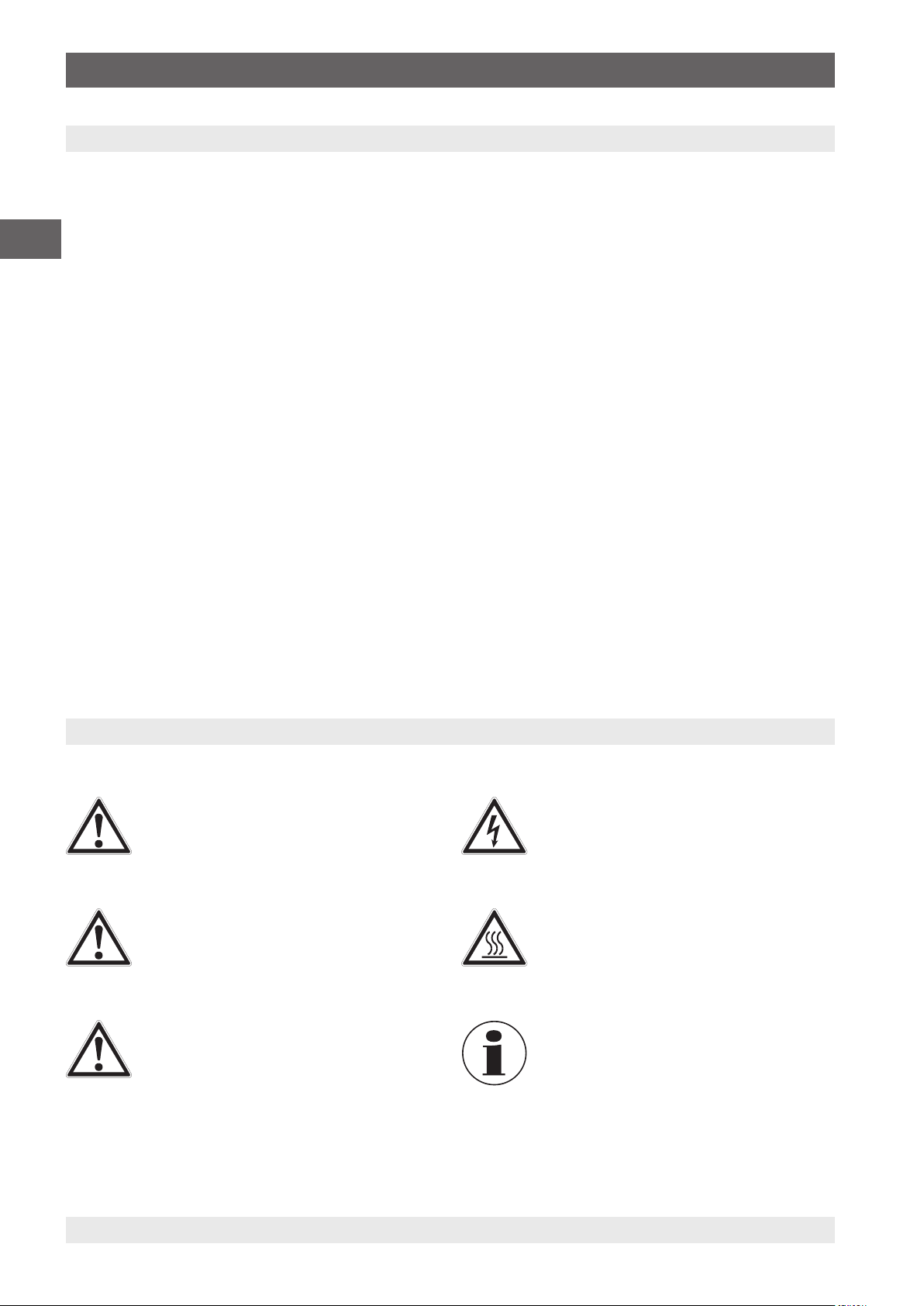
2.1 Explanation of symbols
DANGER!
... indicates a directly dangerous situation
resulting in serious injury or death, if not
avoided.
WARNING!
... indicates a potentially dangerous situation
that can result in serious injury or death, if not
avoided.
CAUTION!
... indicates a potentially dangerous situation
that can result in light injuries or damage to
equipment or the environment, if not avoided.
DANGER!
... identifies hazards caused by electrical power.
Should the safety instructions not be observed,
there is a risk of serious or fatal injury.
WARNING!
... indicates a potentially dangerous situation
that can result in burns, caused by hot surfaces
or liquids, if not avoided.
Information
... points out useful tips, recommendations
and information for efficient and trouble-free
operation.
14031673.03 06/2016 EN/DE/FR/ES/IT
4 WIKA operating instructions temperature dry well calibrator, model CTD9100-ZERO
Page 5
2. Safety
2.2 Intended use
The model CTD9100-ZERO temperature dry-well calibrator
is a portable unit, for service functions and also for industrial
and laboratory tasks. The temperature dry-well calibrator
from WIKA is intended for the calibration of thermometers,
resistance thermometers and thermocouples.
This instrument is not permitted to be used in hazardous
areas!
The instrument has been designed and built solely for
the intended use described here, and may only be used
accordingly.
The technical specifications contained in these operating
instructions must be observed. Improper handling or
operation of the instrument outside of its technical
specifications requires the instrument to be taken out of
service immediately and inspected by an authorised WIKA
service engineer.
Handle electronic precision measuring instruments with
the required care (protect from humidity, impacts, strong
magnetic fields, static electricity and extreme temperatures,
do not insert any objects into the instrument or its openings).
Plugs and sockets must be protected from contamination.
If the instrument is transported from a cold into a warm
environment, the formation of condensation may result
in instrument malfunction. Before putting it back into
operation, wait for the instrument temperature and the room
temperature to equalise.
The safety instructions within these operating instructions,
as well as the safety, accident prevention and environmental
protection regulations for the application area must be
maintained.
The operator is obliged to maintain the product label in a
legible condition.
2.5 Personnel qualification
WARNING!
Risk of injury should qualification be
insufficient
Improper handling can result in considerable
injury and damage to equipment.
▶
The activities described in these operating
instructions may only be carried out by
skilled personnel who have the qualifications
described below.
Skilled personnel
Skilled personnel, authorised by the operator, are understood
to be personnel who, based on their technical training,
knowledge of measurement and control technology and
on their experience and knowledge of country-specific
regulations, current standards and directives, are capable
of carrying out the work described and independently
recognising potential hazards.
Special operating conditions require further appropriate
knowledge, e.g. of aggressive media.
EN
The manufacturer shall not be liable for claims of any type
based on operation contrary to the intended use.
2.3 Improper use
WARNING!
Injuries through improper use
Improper use of the instrument can lead to
hazardous situations and injuries.
▶
Refrain from unauthorised modifications to
the instrument.
▶
Do not use the instrument within hazardous
areas.
Any use beyond or different to the intended use is considered
as improper use.
2.4 Responsibility of the operator
The instrument is used in the industrial sector. The operator
is therefore responsible for legal obligations regarding safety
at work.
14031673.03 06/2016 EN/DE/FR/ES/IT
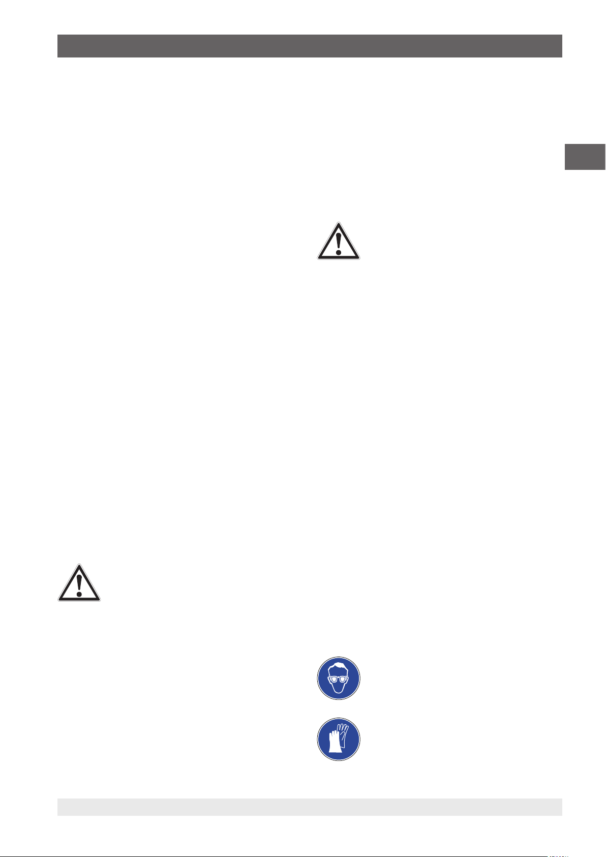
2.6 Personal protective equipment
The personal protective equipment is designed to protect the
skilled personnel from hazards that could impair their safety
or health during work. When carrying out the various tasks
on and with the instrument, the skilled personnel must wear
personal protective equipment.
Follow the instructions displayed in the work area
regarding personal protective equipment!
The requisite personal protective equipment must be
provided by the operating company.
Wear safety goggles!
Protect eyes from flying particles and liquid
splashes.
Wear protective gloves!
Protect hands from contact with hot surfaces
and aggressive media.
WIKA operating instructions temperature dry well calibrator, model CTD9100-ZERO 5
Page 6
2. Safety / 3. Design and function
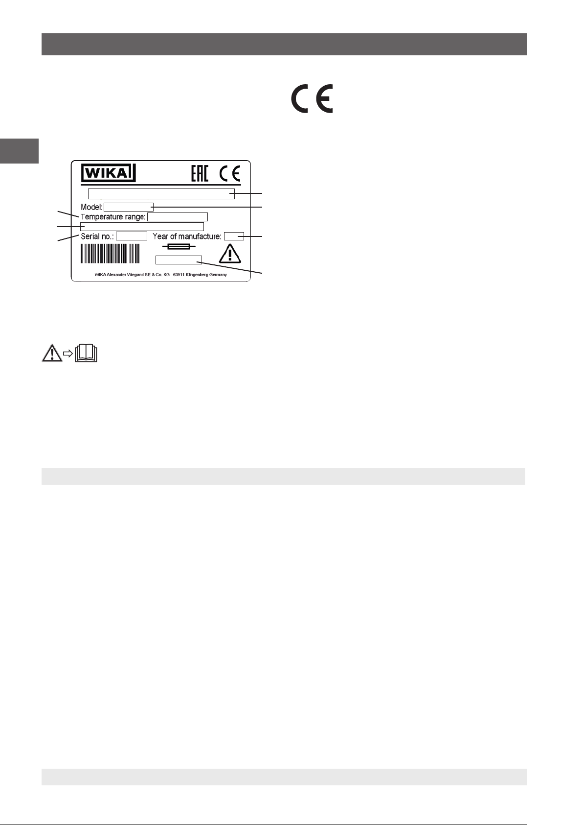
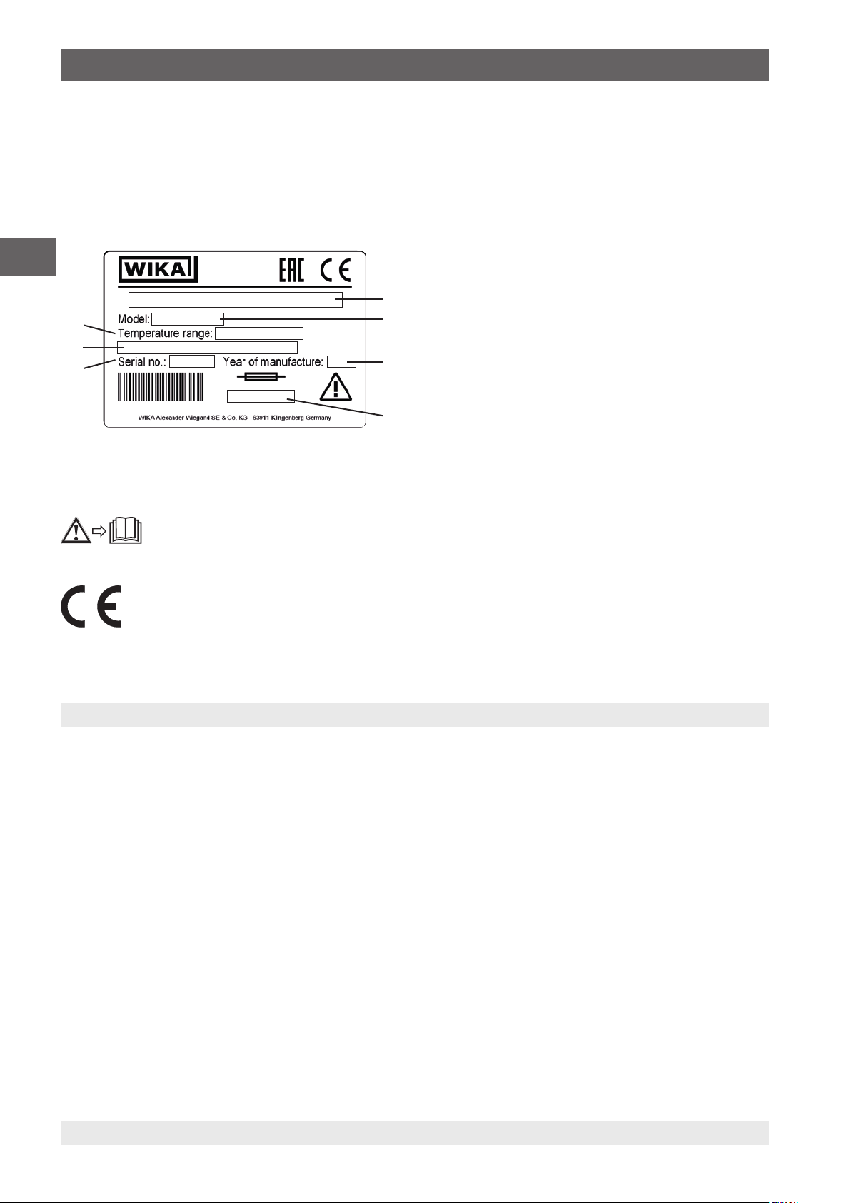
2.7 Labelling, safety marks
Product label (example)
On the rear of the instrument is the product label with the key
information about the temperature dry-well calibrator
EN
Symbols
Before mounting and commissioning the
instrument, ensure you read the operating
instructions!
CE, Communauté Européenne
Instruments bearing this mark comply with
the relevant European directives.
Instrument designation
Model
Year of manufacture
Fuse
Serial no.
Power supply
Temperature range
3. Design and function
3.1 Description
The model CTD9100-ZERO temperature dry-well calibrator
is a portable unit, for service functions and also for industrial
and laboratory tasks. The temperature dry-well calibrator
is intended for the calibration of thermometers, resistance
thermometers and thermocouples.
In a simple way, a lasting cold junction temperature can
be generated and thus the calibration of thermocouples is
simplified. The complex method of water fixed-point cells and
the risk of freezing and damage in transport are avoided. The
CTD9100-ZERO, as a freezing-point calibrator, can deliver
not only the zero point in °C, but also, through the active
cooling, it can reach other test temperatures.
Due to its design and the control, an even temperature
distribution is achieved within the block. On this basis,
the temperature can be taken as homogenous and not as
distributed over the seven test bores. This homogenous
temperature distribution reduces the influences on
measurement uncertainty.
The CTD9100-ZERO represents state-of-the-art technology.
This applies to measurement accuracy, functionality and
the safe operation of the instrument. The operating position
is defined as upright, since this achieves the optimum
temperature distribution. The set temperature of the heating
block is displayed on a large, 4-digit, high-contrast LED
display. For easy reading of the temperature, the display is
not only large, but, in addition, is also angled by 35°.
The operational safety is only assured if the equipment is
employed for its intended use. The given limit values should
never be exceeded (see chapter 10 “Specifications“).
14031673.03 06/2016 EN/DE/FR/ES/IT
6 WIKA operating instructions temperature dry well calibrator, model CTD9100-ZERO
Page 7
3. Design and function
3.2 Scope of delivery
The temperature dry-well calibrator is delivered in special
protective packaging. The packaging must be set aside
so that the calibrator can be sent safely back to the
manufacturer for recalibration or repair.
■
Temperature dry-well calibrator
■
1.5 m (5 ft) power cord with mains plug
■
Operating instructions in German and English language
■
Calibration certificate 3.1 per to DIN EN 10204
Cross-check scope of delivery with delivery note.
WARNING!
Damage through incorrect power cord
If a third-party power cord is used, incorrect
voltages can occur at the instrument.
▶
Only ever use the power cord supplied.
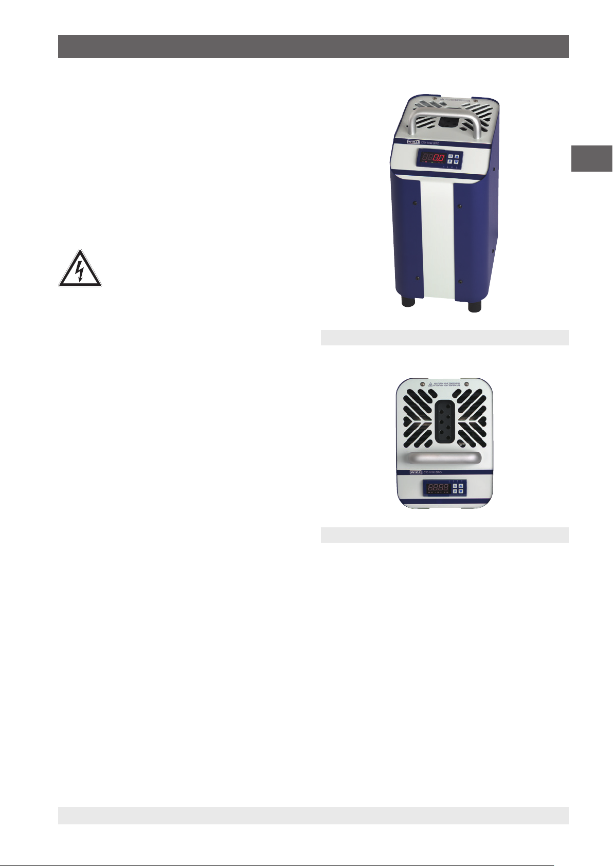
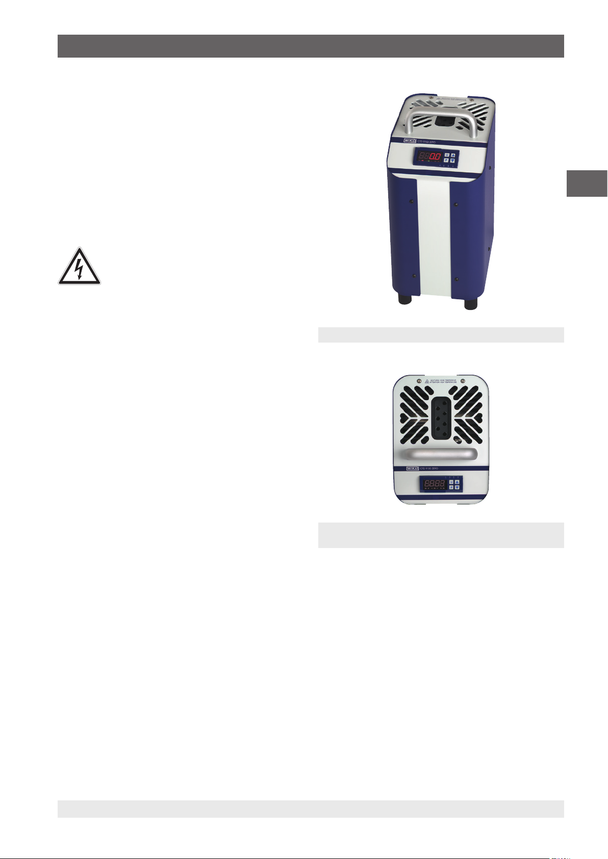
3.3 Overview
The calibrator consists of a robust, grey-blue painted steel
case, with a carrying handle on top.
The rear part of the case includes a metal block with seven
bores for the test items, accessible from the top.
The metal block incorporates the heating or cooling elements
and the temperature sensor for determining the reference
temperature.
The metal block is thermally insulated.
EN
Fig. 1: Temperature dry-well calibrator
The front part of the case contains the complete electronic
unit for controlling the reference temperature.
Solid state relays (SSR) are used to control the heating and
cooling elements.
On the front panel is the controller, which is fitted with a
4-digit, high-contrast LED display for the reference and set
temperature.
Fig. 2: Temperature block with seven test bores
14031673.03 06/2016 EN/DE/FR/ES/IT
WIKA operating instructions temperature dry well calibrator, model CTD9100-ZERO 7
Page 8

3. Design and function
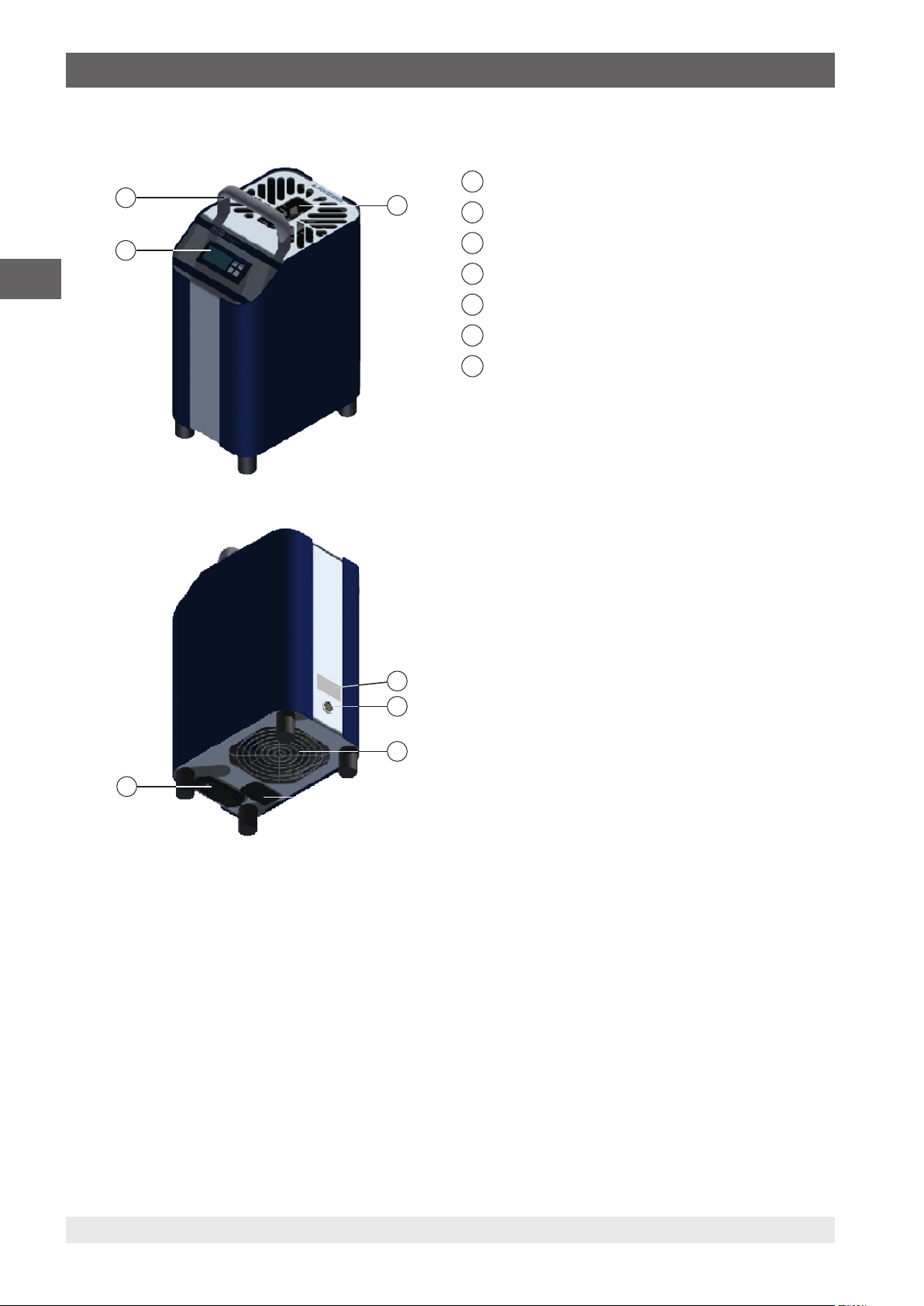
3.4 Isometric view
3
1
Temperature block
1
2
Controller
EN
3
2
Handle
4
Product label
5
RS-485 interface
6
Fan
7
C14 connector with mains filter and On/Off switch
Front and top
The controller, with display and controls, is located on the
front of the calibrator.
On the top of the temperature dry-well calibrator, you will find
the metal block with seven test bores for inserting the test
items.
Rear of the instrument
At the rear of the instrument, you will find the product label
with the key information about the relevant model, the serial
4
5
number, the mains voltage and the fuse rating.
Below the product label is the connector for the RS-485
interface.
6
7
Underside of the instrument
On the underside of the instrument are the mains connector
and the mains switch with its fuse holder.
These are located in the centre, at the front. Furthermore, on
the underside of the instrument, there is an air inlet and the
C13 panel socket for the supply of the operating voltage.
Do not obstruct the air inlet in any way!
8 WIKA operating instructions temperature dry well calibrator, model CTD9100-ZERO
14031673.03 06/2016 EN/DE/FR/ES/IT
Page 9

3. Design and function
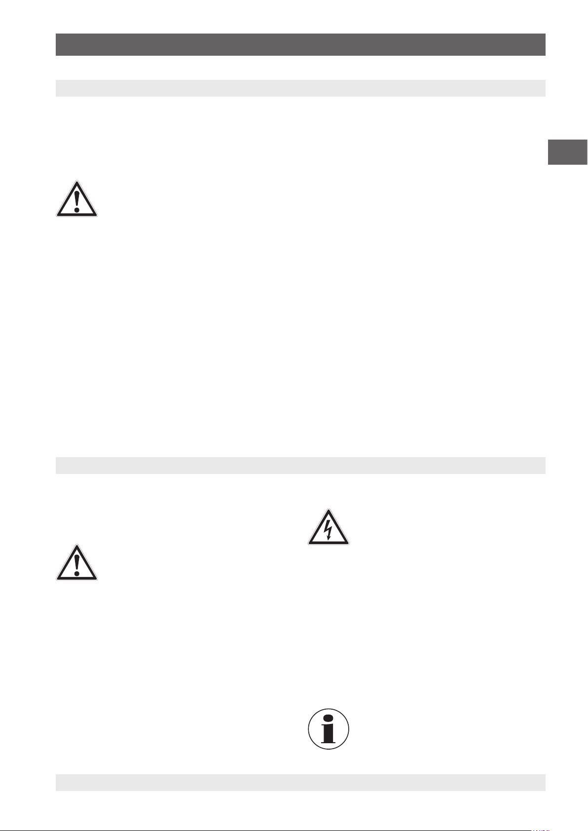
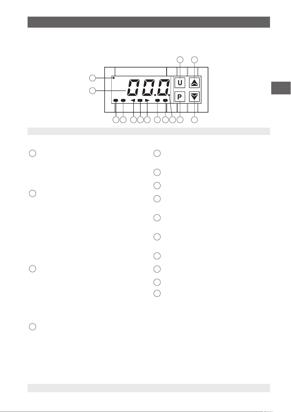
3.5 Function keys and LEDs
The calibrator’s controller can be easily operated via four keys.
1 2
14
13
Fig. 3: Overview of the operating elements on the front of the controller
Function keys and their meaning:
Recall key, key U (U key)
1
Recall the stored set temperatures
This key can be defined individually via the parameter
“USrb”. In its basic setting, one can select the memory
locations SP1 to SP4 when the key is pressed for
longer than 1 s.
Increase key, key ▲ (UP key)
2
■
Increase of values to be set
■
Selection of individual menu items
■
Go back up one menu level
The key is used for increasing a value to be set and
selecting parameters. If the key is held down, it takes
the user to the previous menu level, and remains there
until the programming mode is exited. Outside of the
programming mode, this key allows display of the
current, controlled output power.
Decrease key, key ▼ (DOWN key)
3
■
Reduction of values to be set
■
Selection of individual menu items
■
Go back up one menu level
The key is used for decreasing a value to be set and
selecting parameters. If the key is held down, it takes
the user to the previous menu level, and remains there
until the programming mode is exited.
Programming key, key P (P key)
4
■
Access to the set temperature parameter
■
Access to the menu items and parameters
■
Input confirmation
346 5789101112
Flashing LEDs and their meaning:
LED SET
5
When blinking, access to the program menu is
possible.
LED AL2
6
Alarm output (status) AL2
LED AL1
7
Alarm output (status) AL1
LED + Shift index
8
The temperature value is greater than that set in
parameter “AdE”
LED = Shift index
9
The temperature value is within the span of the set
parameters [SP+AdE ... SP-AdE].
LED – Shift index
10
The temperature value is lower than that set in
parameter “AdE”
LED Cool
11
The calibrator is cooling
LED Heat
12
The calibrator is heating
Current temperature display
13
LED AT/ST
14
“Self-tuning” function is activated (lit) or “Auto-tuning” is
currently running (blinking)
EN
With this key one confirms a selection. If it is pressed
for longer than 5 s, then one reaches the program
level. One can exit the program level at any time using
the UP key.
14031673.03 06/2016 EN/DE/FR/ES/IT
WIKA operating instructions temperature dry well calibrator, model CTD9100-ZERO 9
Page 10

3. Design and function
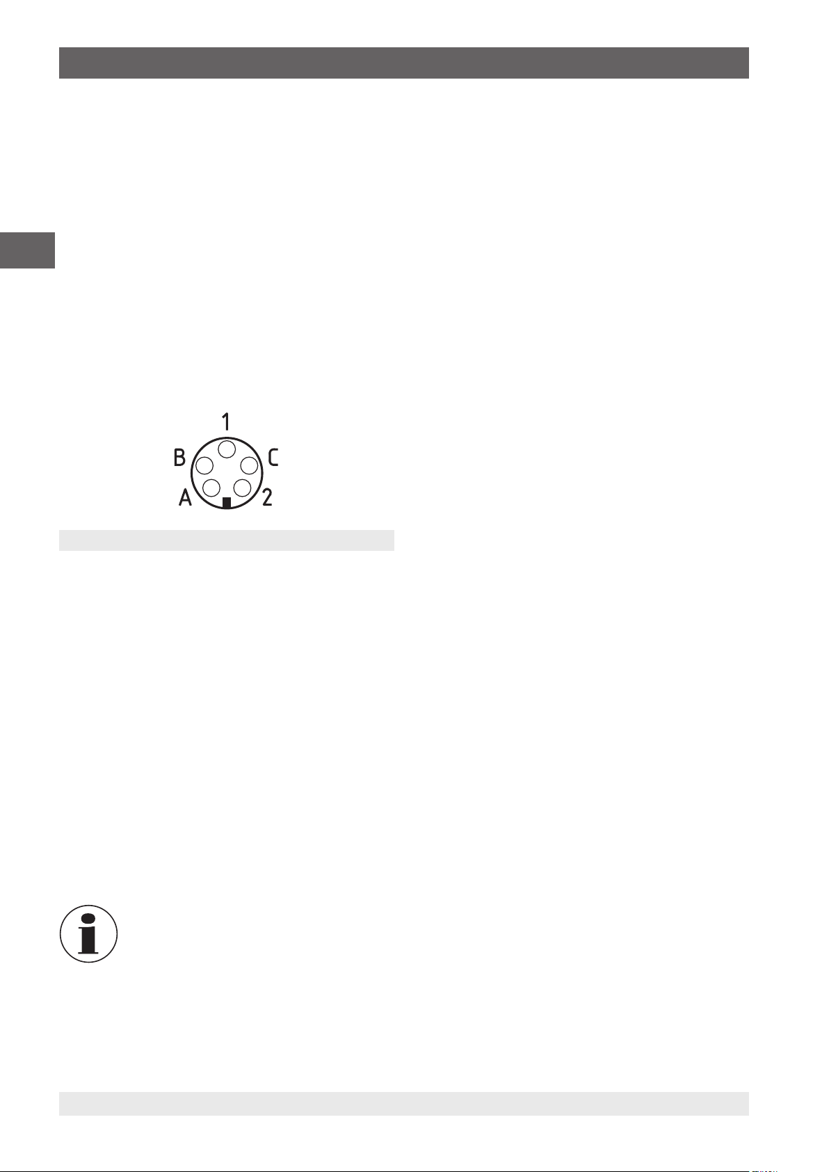
3.6 Data interface
The instruments are fitted with a serial RS-485
communication interface. Via this interface one can connect
to a PC, level converter or a network.
The software protocol used is a MODBUS-RTU protocol,
EN
which is used in many monitoring programs available on the
market.
The transmission rate (baud rate) is factory set to
9,600 baud. Upon request, other transmission rates are
possible.
The 5-pin panel socket has two pins, A and B, that you
connect to the corresponding connections on the PC, level
converter or network.
Fig. 4: Plan view of the 5-pin panel socket
3.7 Interface protocol
The interface protocol is available on request for delivery as a
specific additional document.
3.8 Protective conductor monitoring
The calibrator is fitted with a protective conductor monitor
to keep a check on the base isolation of the heater. The
monitoring unit works independently of the normal control
and switches off the heating power supply as soon as the
calibrator no longer has a connection to the protective
conductor system.
Once reconnected to the protective conductor system, the
monitoring unit automatically switches the power supply back
on to the heating circuit.
To connect to a PC, the RS-485 signal must be externally
converted to a RS-232 or USB signal. The appropriate
converter, including drivers, is available as an option.
The computer records all operational data and allows
programming of all calibrator configuration parameters.
The minimum requirements for operation with a USB
converter are:
■
IBM compatible PC
■
Installed operating system, Microsoft® Windows® 98 SE,
ME, 2000, XP (Home or Prof.) or 7
■
A USB interface (USB 1.1 or USB 2.0)
A network connection enables the connection of up to 32
calibrators/micro-baths on the same network.
To connect to a network, some factory settings are required.
For this, please contact the supplier or WIKA directly.
On access to the programming via the keypad
while the serial interface is communicating, the
message “buSy” appears on the display, and
therefore indicates that it is in an “occupied”
state.
10 WIKA operating instructions temperature dry well calibrator, model CTD9100-ZERO
14031673.03 06/2016 EN/DE/FR/ES/IT
Page 11
4. Transport, packaging and storage / 5. Commissioning, operation
4. Transport, packaging and storage
4.1 Transport
Check the model CTD9100-ZERO temperature dry-well
calibrator for any damage that may have been caused by
transport.
Obvious damage must be reported immediately.
CAUTION!
Damage through improper transport
With improper transport, a high level of damage
to property can occur.
▶
When unloading packed goods upon delivery
as well as during internal transport, proceed
carefully and observe the symbols on the
packaging.
▶
With internal transport, observe the
instructions in chapter 4.2 “Packaging and
storage“.
If the instrument is transported from a cold into a warm
environment, the formation of condensation may result
in instrument malfunction. Before putting it back into
operation, wait for the instrument temperature and the room
temperature to equalise.
4.2 Packaging and storage
Do not remove packaging until just before mounting.
Keep the packaging as it will provide optimum protection
during transport (e.g. change in installation site, sending for
repair).
Permissible conditions at the place of storage:
■
Storage temperature: 0 ... 60 °C (32 ... 140 °F)
■
Humidity: 35 ... 85 % relative humidity (no condensation)
Avoid exposure to the following factors:
■
Direct sunlight or proximity to hot objects
■
Mechanical vibration, mechanical shock (putting it down
hard)
■
Soot, vapour, dust and corrosive gases
■
Hazardous environments, flammable atmospheres
Store the temperature dry-well calibrator in its original
packaging in a location that fulfils the conditions listed above.
If the original packaging is not available, pack and store the
instrument as described below:
1. Place the instrument, along with shock-absorbent
material, in the packaging.
2. If stored for a prolonged period of time (more than 30
days), place a bag containing a desiccant inside the
packaging.
EN
5. Commissioning, operation
Personnel: skilled personnel
Protective equipment: safety goggles, protective gloves
Only use original parts (see chapter 11 “Accessories“).
WARNING!
Physical injuries and damage to property
and the environment caused by hazardous
media
Upon contact with hazardous media (e.g.
oxygen, acetylene, flammable or toxic
substances), harmful media (e.g. corrosive,
toxic, carcinogenic, radioactive), and also with
refrigeration plants and compressors, there is
a danger of physical injuries and damage to
property and the environment.
▶
For these media, in addition to all standard
regulations, the appropriate existing codes or
regulations must also be followed.
▶
Wear the requisite protective equipment (see
chapter 2.6 “Personal protective equipment“).
14031673.03 06/2016 EN/DE/FR/ES/IT
5.1 Operating position
DANGER!
Danger to life caused by electric current
Upon contact with live parts, there is a direct
danger to life.
▶
Operation using a defective power cord (e.g.
short-circuit from the mains voltage to the
output voltage) can result in life-threatening
voltages at the instrument!
■
The operating position of the temperature dry-well
calibrator is in the vertical orientation, since this
guarantees an optimal temperature distribution in the
metal block.
■
Place the temperature dry-well calibrator on a clean
surface so that the fan on the bottom is not blocked and
sufficient fresh air can be drawn in.
Insufficient ventilation can lead to damage to the
calibrator.
WIKA operating instructions temperature dry well calibrator, model CTD9100-ZERO 11
Page 12
5. Commissioning, operation
5.2 Switching on the calibrator
1. Connect to the mains supply using the power cord
supplied.
Only connect the instrument to circuits where
EN
2. Switch on the mains switch.
The controller will be initialised.
After approx. 5 s, the initialisation will be complete and the
calibration mode will automatically be displayed.
The 4-digit LED display of the controller will now show the
last set temperature set. The built-in heating or cooling
elements will temper the metal block automatically from room
temperature to the set temperature.
Once the selected set temperature has been reached,
through short switch impulses, the radiated heating energy
from the metal block is delivered, so that the temperature
within remains constant.
the risk of a power outage has been minimised
as far as possible, since during any power
outage cooling air will not be available.
The main switch is located on the underside of
the instrument, in the centre, at the front. After
a short self-test, the controller starts to regulate
the temperature in the block to the last, set
value.
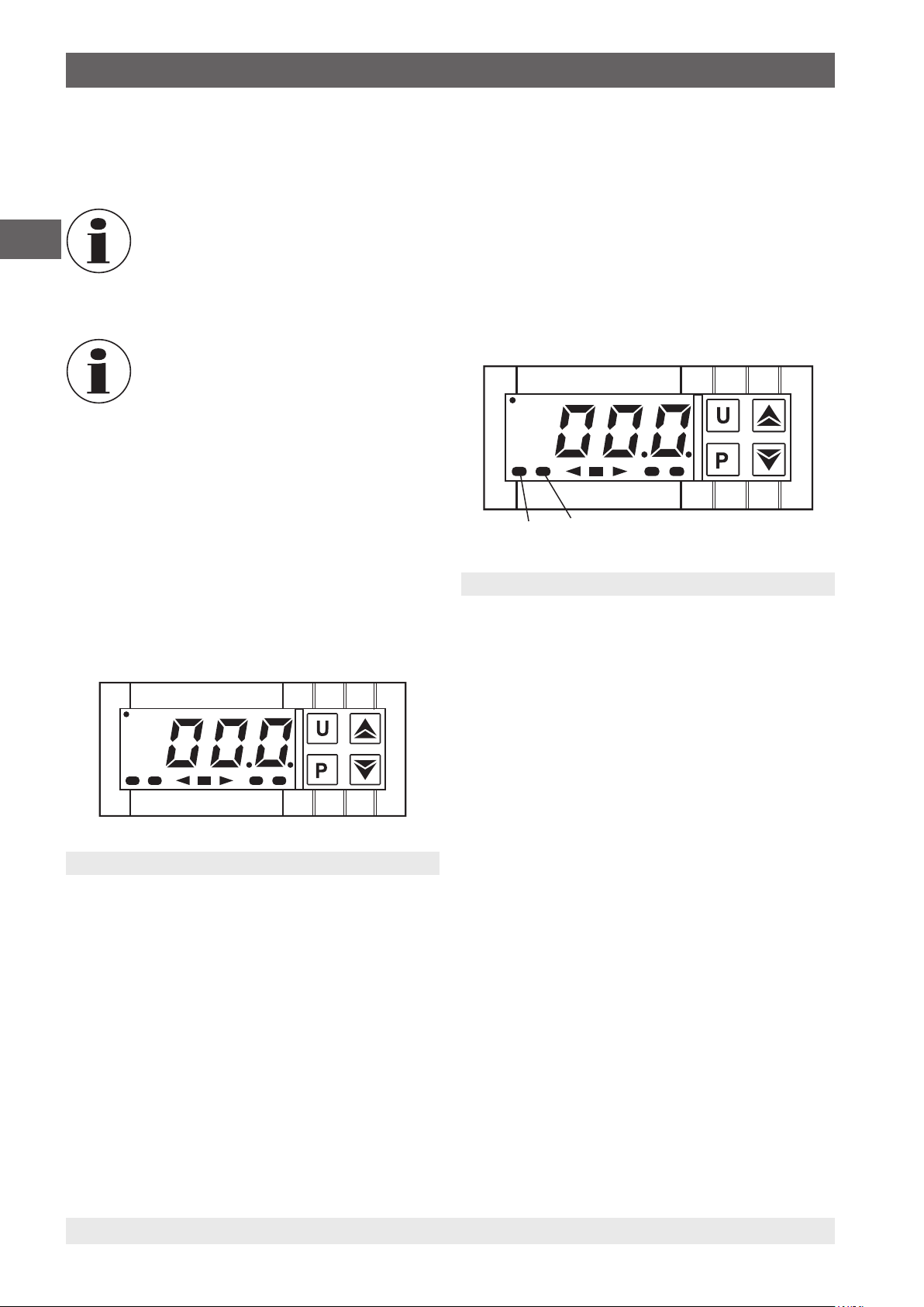
5.3 Calibration (calibration mode)
As soon as the calibrator is switched on, following the
initialisation, it defaults to calibration mode.
On the display, the selected set temperature is displayed.
The LED Heat and LED Cool signal the status of the output
for the heating control:
■
If the LED Heat is on, the temperature will increase.
■
If the LED Heat is not on, the heating is switched off.
■
If the LED Cool is on, the temperature will decrease.
■
If the LED Cool is not on, the cooling is switched off.
LED Heat LED Cool
Fig. 6: Display with LED Heat and LED Cool
During the heating or cooling phase, a continuous light
indicates the supply of heating or cooling energy. A flashing
LED indicates that the selected set temperature has almost
been reached and therefore the heating or cooling energy is
only being supplied in short bursts.
To ensure good temperature stability, the cycle time of the
controller is set low and the control output is usually raised.
5.4 Setting a set temperature
In this operating state, a stored set temperature is temporarily
changed.
1. Press key P briefly.
Fig. 5: Set temperature display
5.2.1 Start-up procedure
If the calibrator is not used for a long time, because of the
materials used (magnesium oxide), moisture can penetrate
the heating elements.
Following transport or storage of the calibrator in moist
environments, the heating elements must be taken to higher
temperatures slowly.
12 WIKA operating instructions temperature dry well calibrator, model CTD9100-ZERO
On the display, the currently active set temperature is
⇒
displayed.
2. By pressing the ▲ key, the set temperature is increased.
By pressing the ▼ key, the set temperature is decreased.
3. By pressing key P again, the new selected set point is
accepted.
14031673.03 06/2016 EN/DE/FR/ES/IT
Page 13
5. Commissioning, operation / 6. Cooling down the metal block
5.5 Measuring or calibrating a temperature sensor
1. All bores in the insert must be clean, undamaged and free
from any foreign bodies.
2. Test item and also the bore in the block must match
each other exactly so that the resistance to heat transfer
remains as low as possible.
3. For setting the temperature via the controller, see chapter
5.4 “Setting a set temperature“.
4. If a set temperature has been controlled, wait until the
temperature has been reached and wait approx. a further
10 minutes so that a thermal equilibrium can be settled.
5. Then read or measure the test item.
6. Once the measurement has been completed, the
temperature dry-well calibrator can be allowed to cool.
(also see chapter 6 “Cooling down the metal block“)
WARNING!
Risk of burns!
Before removing the temperature sensor or
test item, ensure that the temperature dry-well
calibrator has cooled sufficiently, otherwise
there is a serious danger of burns from both the
metal block and also the test item.
▶
In order that the metal block can be brought
quickly from a higher to a lower temperature,
set the set temperature to a lower
temperature (e.g. room temperature).
▶
Always cool the heated instrument under
50 °C (122 °F) before removing the
temperature sensor or test item.
▶
Never leave a heated instrument
unsupervised.
7. After cooling, pull the temperature sensor or test item out
from the metal block.
5.5.1 Testing of temperature sensors
To test temperature sensors, connect a separate temperature
measuring instrument to the test item. By comparing the
temperature displayed on the external measuring instrument
with the reference temperature, there is evidence of the
status of the test item. Here, pay attention to the fact that the
test item requires a short time until it reaches the temperature
of the metal block.
There is no possibility for calibrating grounded
thermocouples, since the heating block is
earthed and this would therefore lead to false
measurement results.
EN
6. Cooling down the metal block
WARNING!
Risk of burns!
Before transport of or contact with the metal
block, ensure that the temperature dry-well
calibrator has cooled sufficiently, otherwise
there is a serious danger of burns from both the
metal block and also the test item.
▶
In order that the metal block can be brought
quickly from a higher to a lower temperature,
set the set temperature to a lower
temperature (e.g. room temperature).
▶
Always cool the heated instrument under
50 °C (122 °F) before disconnecting it from
the mains, switching it off or removing the
temperature sensor or test item.
▶
Never leave a heated instrument
unsupervised.
14031673.03 06/2016 EN/DE/FR/ES/IT
WIKA operating instructions temperature dry well calibrator, model CTD9100-ZERO 13
With a heating instrument, the built-in ventilator will
automatically slowly switch to higher speed, which will
provide a cooling airflow.
After switching off or removing the mains
connection, no cooling air will be provided
by the built-in ventilator. A sufficient thermal
decoupling between the metal block and case is
nevertheless ensured.
Page 14
7. Faults
7. Faults
Personnel: skilled personnel
Protective equipment: safety goggles, protective gloves
EN
Error Causes Measures
- - - - Interruption of the internal reference sensor or the
uuuu Measured temperature under the limit value of the
oooo Measured temperature over the limit value of the
ErEP Possible error in the controller's EEPROM
Fan is not running Fan is defective or blocked.
Final temperature is not
reached
No display The controller is defective.
No function The mains connection is not made properly or the
CAUTION!
Physical injuries and damage to property
and the environment
If faults cannot be eliminated by means of the
listed measures, the model CTD9100-ZERO
temperature dry-well calibrator must be taken
out of operation immediately.
▶
Ensure that there is no longer any voltage
present and protect against being put into
operation accidentally.
▶
Contact the manufacturer.
▶
If a return is needed, please follow the
instructions given in chapter 9.2 “Return“.
internal reference sensor is defective.
internal reference sensor (underrange -200 °C
(-328 °F)).
internal reference sensor (overrange +850 °C
(+1.562 °F)).
memory.
The temperature switch may have been triggered
and the current supply to the heating elements
switched off.
Solid state relay defective, or the heating-cooling
element has a short-circuit or has aged.
fuse is defective.
For contact details, please see chapter
1 “General information“ or the back page of the
operating instructions.
Send the instrument back to the manufacturer or
service partner for repair.
Press key P.
Send the instrument back to the manufacturer or
service partner for repair.
Check the mains connection and fuse.
Thermal fuse
For safety, the calibrator is fitted with an
independently operating thermal fuse, which
cuts out the heater current supply if the
temperature inside the case is too high. Once
the metal block has cooled down, send the
calibrator to WIKA for examination.
14 WIKA operating instructions temperature dry well calibrator, model CTD9100-ZERO
14031673.03 06/2016 EN/DE/FR/ES/IT
Page 15
8. Maintenance, cleaning and recalibration
8. Maintenance, cleaning and recalibration
Personnel: skilled personnel
Protective equipment: safety goggles, protective gloves
For contact details, please see chapter
1 “General information“ or the back page of the
operating instructions.
8.1 Maintenance
The model CTD9100-ZERO temperature dry-well calibrator
is maintenance-free.
Repairs must only be carried out by the manufacturer.
This does not apply to the fuse replacement.
Before replacing the fuse, the calibrator must be
disconnected by unplugging the power cord from the mains
voltage.
Only use original parts (see chapter 11 “Accessories“).
8.2 Cleaning
CAUTION!
Physical injuries and damage to property
and the environment
Improper cleaning may lead to physical injuries
and damage to property and the environment.
Residual media in the temperature dry-well
calibrator can result in a risk to personnel, the
environment and equipment.
▶
Carry out the cleaning process as described
below.
1. Cool down the calibrator as described in chapter
6 “Cooling down the metal block“.
2. Prior to cleaning, switch off and disconnect the calibrator
from the mains.
3. Use the requisite protective equipment.
4. Clean the instrument with a moist cloth. Electrical
connections must not come into contact with moisture!
8.2.1 Cleaning the metal block
With calibrators, during operation, a small amount of metallic
dust can cause the block and the test item to become
jammed. To prevent this, on a regular basis and before any
long period the calibrator will be out of use, purge the test
bores with compressed air.
8.2.2 Cleaning fan guards
On the base of each calibrator is a dense air grille, through
which the cooling air is supplied to the calibrator. Depending
on the cleanliness of the air, clean the grille at regular
intervals by vacuuming or brushing.
8.2.3 External cleaning
Clean the outside of the calibrator with a damp cloth and
some water, or with a solvent-free light detergent.
8.3 Recalibration
DKD/DAkkS certificate - official certificates:
The temperature dry-well calibrator has been adjusted and
tested before delivery using measuring devices that are
traceable to nationally recognised standards.
On the basis of DIN ISO 10012, the calibrator, depending
on the application, should be verified at appropriate periodic
intervals.
We recommend that the instrument is regularly recalibrated
by the manufacturer, with time intervals of approx. 12 months
or approximately 500 hours of operation.
In addition, every factory recalibration includes an extensive
free-of-charge check of all system parameters with respect to
their compliance with the specification. The basic settings will
be corrected if necessary.
The basis of the recalibration is the guidelines of the German
Calibration Service, DKD R5-4. The measures described
here should be used and followed for recalibration.
EN
CAUTION!
Damage to property
Improper cleaning may lead to damage to the
instrument!
▶
Do not use any aggressive cleaning agents.
▶
Do not use any pointed and hard objects for
cleaning.
5. Wash or clean the temperature dry-well calibrator, in
order to protect persons and the environment from
exposure to residual media.
14031673.03 06/2016 EN/DE/FR/ES/IT
WIKA operating instructions temperature dry well calibrator, model CTD9100-ZERO 15
Page 16
Contents
9. Decommissioning, return and disposal
Personnel: skilled personnel
Protective equipment: safety goggles, protective gloves
EN
9.1 Decommissioning
1. Cool down the calibrator as described in chapter
6 “Cooling down the metal block“.
2. Switch off and disconnect the calibrator from the mains.
WARNING!
Physical injuries and damage to property
and the environment through residual
media
Residual media in the temperature dry-well
calibrator can result in a risk to personnel, the
environment and equipment.
▶
Wear the requisite protective equipment (see
chapter 2.6 “Personal protective equipment“).
▶
Observe the information in the material safety
data sheet for the corresponding medium.
▶
Wash or clean the dismounted instrument, in
order to protect persons and the environment
from exposure to residual media.
WARNING!
Risk of burns
During decommissioning, there is a risk of
dangerously hot media escaping.
▶
Let the instrument cool down sufficiently
before decommissioning it!
DANGER!
Danger to life caused by electric current
Upon contact with live parts, there is a direct
danger to life.
▶
The dismounting of the instrument may only
be carried out by skilled personnel.
▶
Disconnect test and calibration installations
once the system has been isolated from
power sources.
WARNING!
Physical injury
When decommissioning, there is a danger from
aggressive media.
▶
Wear the requisite protective equipment (see
chapter 2.6 “Personal protective equipment“).
▶
Observe the information in the material safety
data sheet for the corresponding medium.
9.2 Return
Strictly observe the following when shipping the
instrument:
All instruments delivered to WIKA must be free from any kind
of hazardous substances (acids, bases, solutions, etc.) and
must therefore be cleaned before being returned.
WARNING!
Physical injuries and damage to property
and the environment through residual
media
Residual media in the temperature dry-well
calibrator can result in a risk to personnel, the
environment and equipment.
▶
With hazardous substances, include
the material safety data sheet for the
corresponding medium.
Clean the instrument, see chapter 8.2 “Cleaning“.
When returning the instrument, use the original packaging or
a suitable transport packaging.
To avoid damage:
1. Place the instrument, along with shock-absorbent
material, in the packaging. Place shock-absorbent
material evenly on all sides of the transport packaging.
2. If possible, place a bag containing a desiccant inside the
packaging.
3. Label the shipment as carriage of a highly sensitive
measuring instrument.
Information on returns can be found under the
heading “Service” on our local website.
9.3 Disposal
Incorrect disposal can put the environment at risk.
Dispose of instrument components and packaging materials
in an environmentally compatible way and in accordance with
the country-specific waste disposal regulations.
This marking on the instruments indicates that
they must not be disposed of in domestic waste.
The disposal is carried out by return to the
manufacturer or by the corresponding municipal
authorities (see EU directive 2012/19/EU).
16 WIKA operating instructions temperature dry well calibrator, model CTD9100-ZERO
14031673.03 06/2016 EN/DE/FR/ES/IT
Page 17
10. Specifications
10. Specifications
Specifications CTD9100-ZERO
Display
Temperature range -10 … 0 … +100 °C (14 ... 32 ... 212 °F)
Accuracy
Stability
Resolution 0.1 °C
Temperature distribution
Axial homogeneity
Temperature control
Heating time 15 min from -10 °C to +100 °C (from 14 °F to 212 °F)
Cooling time 5 min from 23 °C to 0 °C (from 73 °F to 14 °F)
Stabilisation time
Metal block
Immersion depth 150 mm (5.91 in)
Test bores 7 bores with Ø 6.5 mm (0.26 in)
Block material Aluminium
Voltage supply
Power supply
Power consumption 225 VA
Fuse 3.15 A slow blow fuse (at AC 250 V)
Power cord for Europe, AC 230 V
Communication
Interface RS-485
Case
Dimensions (W x D x H) 160 x 230 x 320+50 mm (6.3 x 9.1 x 12.6+2 in)
Weight 7 kg (15.5 lbs)
1) Is defined as the measuring deviation between the measured value and the reference value.
2) Maximum temperature difference at a stable temperature over 30 minutes.
3) The gradient is understood to be the temperature change in the test well over the first 40 mm from the bottom of the insert.
4) Time before reaching a stable value.
5) AC 115 V power supply must be specified on the order, otherwise an AC 230 V one will be delivered.
1)
2)
3)
4)
5)
0.05 K at 0 °C (32 °F), otherwise 0.1 K
< 0.05 K
< 0.05 K
10 min from 100 °C to 0 °C (from 212 °F to 14 °F)
depending upon usage and area of application
AC 100 ... 240 V, 50/60 Hz
EN
The measurement uncertainty is defined as the total measurement uncertainty (k = 2), which contains the following shares:
accuracy, measurement uncertainty of reference, stability and homogeneity.
14031673.03 06/2016 EN/DE/FR/ES/IT
WIKA operating instructions temperature dry well calibrator, model CTD9100-ZERO 17
Page 18
10. Specifications / 11. Accessories
Approvals
Logo Description Country
EU declaration of conformity
■
EMC directive
EN
- MTSCHS
EN 61326, emission (group 1, class B) and interference immunity (industrial application)
■
Low voltage directive
EN 61010, safety requirements for electrical equipment for measurement, control and
laboratory use
EAC
■
Electromagnetic compatibility
■
Low voltage directive
GOST
Metrology, measurement technology
KazInMetr
Metrology, measurement technology
Permission for commissioning
BelGIM
Metrology, measurement technology
Uzstandard
Metrology, measurement technology
European Community
Eurasian Economic
Community
Russia
Kazakhstan
Kazakhstan
Belarus
Uzbekistan
Certificates
Certificate
Calibration Standard: 3.1 calibration certificate per DIN EN 10204
Option: DKD/DAkkS calibration certificate
Recommended recalibration interval 1 year (dependent on conditions of use)
Approvals and certificates, see website
For further specifications see WIKA data sheet CT 41.30 and the order documentation.
11. Accessories
Instrument variant
■
Display in Fahrenheit °F
Calibration
■
DKD/DAkkS calibration certificate only at zero point
Transport case
■
Transport case without castors
■
Transport case with castors
WIKA accessories can be found online at www.wika.com.
Power cord
■
Power cord for Switzerland
■
Power cord for USA/Canada
■
Power cord for UK
18 WIKA operating instructions temperature dry well calibrator, model CTD9100-ZERO
14031673.03 06/2016 EN/DE/FR/ES/IT
Page 19
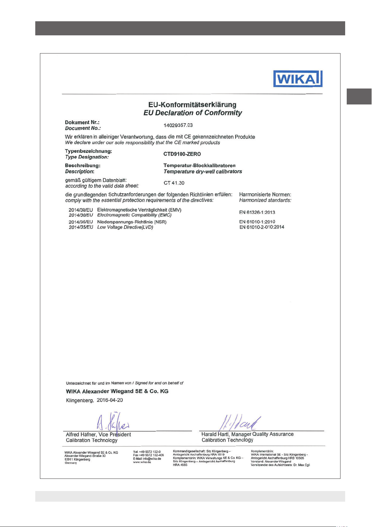
Appendix: EU Declaration of Conformity
EN
14031673.03 06/2016 EN/DE/FR/ES/IT
WIKA operating instructions temperature dry well calibrator, model CTD9100-ZERO 19
Page 20

EN
20 WIKA operating instructions temperature dry well calibrator, model CTD9100-ZERO
14031673.03 06/2016 EN/DE/FR/ES/IT
Page 21

Inhalt
Inhalt
1. Allgemeines 22
2. Sicherheit 22
2.1 Symbolerklärung . . . . . . . . . . . . . . . . . . . . . . . . 22
2.2 Bestimmungsgemäße Verwendung . . . . . . . . . . . . . . . . . . 23
2.3 Fehlgebrauch . . . . . . . . . . . . . . . . . . . . . . . . . 23
2.4 Verantwortung des Betreibers. . . . . . . . . . . . . . . . . . . . 23
2.5 Personalqualifikation . . . . . . . . . . . . . . . . . . . . . . . 23
2.6 Persönliche Schutzausrüstung . . . . . . . . . . . . . . . . . . . 23
2.7 Beschilderung, Sicherheitskennzeichnungen . . . . . . . . . . . . . . 24
3. Aufbau und Funktion 24
3.1 Beschreibung . . . . . . . . . . . . . . . . . . . . . . . . . 24
3.2 Lieferumfang . . . . . . . . . . . . . . . . . . . . . . . . . 25
3.3 Übersicht . . . . . . . . . . . . . . . . . . . . . . . . . . . 25
3.4 Isometrische Ansicht . . . . . . . . . . . . . . . . . . . . . . . 26
3.5 Funktionstasten und LEDs . . . . . . . . . . . . . . . . . . . . . 27
3.6 Datenschnittstelle . . . . . . . . . . . . . . . . . . . . . . . . 28
3.7 Schnittstellenprotokoll . . . . . . . . . . . . . . . . . . . . . . 28
3.8 Schutzleiterüberwachung . . . . . . . . . . . . . . . . . . . . . 28
4. Transport, Verpackung und Lagerung 29
4.1 Transport . . . . . . . . . . . . . . . . . . . . . . . . . . . 29
4.2 Verpackung und Lagerung . . . . . . . . . . . . . . . . . . . . . 29
5. Inbetriebnahme, Betrieb 29
5.1 Betriebslage. . . . . . . . . . . . . . . . . . . . . . . . . . 29
5.2 Einschalten des Kalibrators . . . . . . . . . . . . . . . . . . . . 30
5.2.1 Anfahrprozedur . . . . . . . . . . . . . . . . . . . . . . . . . . . . . . . . . . . . . . . 30
5.3 Kalibrierung (Kalibriermodus) . . . . . . . . . . . . . . . . . . . . 30
5.4 Einstellen einer Soll-Temperatur . . . . . . . . . . . . . . . . . . . 30
5.5 Messen bzw. Kalibieren eines Temperaturfühlers . . . . . . . . . . . . . 31
5.5.1 Prüfen von Temperaturfühlern . . . . . . . . . . . . . . . . . . . . . . . . . . . . . . . 31
6. Abkühlen des Metallblockes 31
7. Störungen 32
8. Wartung, Reinigung und Rekalibrierung 33
8.1 Wartung . . . . . . . . . . . . . . . . . . . . . . . . . . . 33
8.2 Reinigung . . . . . . . . . . . . . . . . . . . . . . . . . . 33
8.2.1 Reinigung des Metallblocks . . . . . . . . . . . . . . . . . . . . . . . . . . . . . . . . 33
8.2.2 Lüftergitterreinigung . . . . . . . . . . . . . . . . . . . . . . . . . . . . . . . . . . . . 33
8.2.3 Außenreinigung. . . . . . . . . . . . . . . . . . . . . . . . . . . . . . . . . . . . . . . 33
8.3 Rekalibrierung . . . . . . . . . . . . . . . . . . . . . . . . . 33
9. Außerbetriebnahme, Rücksendung und Entsorgung 34
9.1 Außerbetriebnahme . . . . . . . . . . . . . . . . . . . . . . . 34
9.2 Rücksendung . . . . . . . . . . . . . . . . . . . . . . . . . 34
9.3 Entsorgung . . . . . . . . . . . . . . . . . . . . . . . . . . 34
10. Technische Daten 35
11. Zubehör 36
Anlage: EU-Konformitätserklärung 37
DE
Konformitätserklärungen finden Sie online unter www.wika.de.
14031673.03 06/2016 EN/DE/FR/ES/IT
WIKA Betriebsanleitung Temperatur-Blockkalibrator, Typ CTD9100-ZERO 21
Page 22
1. Allgemeines / 2. Sicherheit
1. Allgemeines
DE
■
Der in der Betriebsanleitung beschriebene TemperaturBlockkalibrator Typ CTD9100-ZERO wird nach dem
aktuellen Stand der Technik konstruiert und gefertigt.
Alle Komponenten unterliegen während der Fertigung
strengen Qualitäts- und Umweltkriterien. Unsere Managementsysteme sind nach ISO 9001 und ISO 14001 zertifiziert.
■
Diese Betriebsanleitung gibt wichtige Hinweise zum
Umgang mit dem Gerät. Voraussetzung für sicheres
Arbeiten ist die Einhaltung aller angegebenen Sicherheitshinweise und Handlungsanweisungen.
■
Die für den Einsatzbereich des Gerätes geltenden
örtlichen Unfallverhütungsvorschriften und allgemeinen
Sicherheitsbestimmungen einhalten.
■
Die Betriebsanleitung ist Produktbestandteil und muss
in unmittelbarer Nähe des Gerätes für das Fachpersonal
jederzeit zugänglich aufbewahrt werden. Betriebsanleitung an nachfolgende Benutzer oder Besitzer des Gerätes
weitergeben.
■
Das Fachpersonal muss die Betriebsanleitung vor Beginn
aller Arbeiten sorgfältig durchgelesen und verstanden
haben.
■
Es gelten die allgemeinen Geschäftsbedingungen in den
Verkaufsunterlagen.
■
Technische Änderungen vorbehalten.
■
Werkskalibrierungen / DKD/DAkkS-Kalibrierungen erfolgen nach internationalen Normen.
■
Weitere Informationen:
- Internet-Adresse: www.wika.de / www.wika.com
- Zugehöriges Datenblatt: CT 41.30
- Anwendungsberater: Tel.: +49 9372 132-5049
Fax: +49 9372 132-8005049
CTServiceteam@wika.com
2. Sicherheit
2.1 Symbolerklärung
GEFAHR!
... weist auf eine unmittelbar gefährliche Situation hin, die zum Tod oder zu schweren Verletzungen führt, wenn sie nicht gemieden wird.
WARNUNG!
... weist auf eine möglicherweise gefährliche
Situation hin, die zum Tod oder zu schweren
Verletzungen führen kann, wenn sie nicht
gemieden wird.
VORSICHT!
... weist auf eine möglicherweise gefährliche
Situation hin, die zu geringfügigen oder leichten
Verletzungen bzw. Sach- und Umweltschäden
führen kann, wenn sie nicht gemieden wird.
GEFAHR!
... kennzeichnet Gefährdungen durch elektrischen Strom. Bei Nichtbeachtung der Sicherheitshinweise besteht die Gefahr schwerer oder
tödlicher Verletzungen.
WARNUNG!
... weist auf eine möglicherweise gefährliche
Situation hin, die durch heiße Oberflächen oder
Flüssigkeiten zu Verbrennungen führen kann,
wenn sie nicht gemieden wird.
Information
... hebt nützliche Tipps und Empfehlungen
sowie Informationen für einen effizienten und
störungsfreien Betrieb hervor.
22 WIKA Betriebsanleitung Temperatur-Blockkalibrator, Typ CTD9100-ZERO
14031673.03 06/2016 EN/DE/FR/ES/IT
Page 23
2. Sicherheit
2.2 Bestimmungsgemäße Verwendung
Der Temperatur-Blockkalibrator Typ CTD9100-ZERO ist
eine tragbare Einheit sowohl für Servicezwecke als auch für
Industrie- und Laboraufgaben. Der Temperatur-Blockkalibrator von WIKA ist zur Kalibrierung von Thermometern, Widerstandsthermometern und Thermoelementen vorgesehen.
Dieses Gerät ist nicht für den Einsatz in explosionsgefährdeten Bereichen zugelassen!
Das Gerät ist ausschließlich für den hier beschriebenen
bestimmungsgemäßen Verwendungszweck konzipiert
und konstruiert und darf nur dementsprechend verwendet
werden.
Die technischen Spezifikationen in dieser Betriebsanleitung
sind einzuhalten. Eine unsachgemäße Handhabung oder ein
Betreiben des Gerätes außerhalb der technischen Spezifikationen macht die sofortige Stilllegung und Überprüfung durch
einen autorisierten WIKA-Servicemitarbeiter erforderlich.
Elektronische Präzisionsmessgeräte mit erforderlicher
Sorgfalt behandeln (vor Nässe, Stößen, starken Magnetfeldern, statischer Elektrizität und extremen Temperaturen
schützen, keine Gegenstände in das Gerät bzw. Öffnungen
einführen). Stecker und Buchsen vor Verschmutzung schützen.
Wird das Gerät von einer kalten in eine warme Umgebung
transportiert, so kann durch Kondensatbildung eine Störung
der Gerätefunktion eintreten. Vor einer erneuten Inbetriebnahme die Angleichung der Gerätetemperatur an die
Raumtemperatur abwarten.
Ansprüche jeglicher Art aufgrund von nicht bestimmungsgemäßer Verwendung sind ausgeschlossen.
2.3 Fehlgebrauch
WARNUNG!
Verletzungen durch Fehlgebrauch
Fehlgebrauch des Gerätes kann zu gefährlichen
Situationen und Verletzungen führen.
▶
Eigenmächtige Umbauten am Gerät unterlassen.
▶
Gerät nicht in explosionsgefährdeten Bereichen einsetzen.
Jede über die bestimmungsgemäße Verwendung hinausgehende oder andersartige Benutzung gilt als Fehlgebrauch.
Die Sicherheitshinweise dieser Betriebsanleitung, sowie die
für den Einsatzbereich des Gerätes gültigen Sicherheits-,
Unfallverhütungs- und Umweltschutzvorschriften einhalten.
Der Betreiber ist verpflichtet das Typenschild lesbar zu
halten.
2.5 Personalqualifikation
WARNUNG!
Verletzungsgefahr bei unzureichender
Qualifikation
Unsachgemäßer Umgang kann zu erheblichen
Personen- und Sachschäden führen.
▶
Die in dieser Betriebsanleitung beschriebenen Tätigkeiten nur durch Fachpersonal
nachfolgend beschriebener Qualifikation
durchführen lassen.
Fachpersonal
Das vom Betreiber autorisierte Fachpersonal ist aufgrund
seiner fachlichen Ausbildung, seiner Kenntnisse der Messund Regelungstechnik und seiner Erfahrungen sowie
Kenntnis der landesspezifischen Vorschriften, geltenden
Normen und Richtlinien in der Lage, die beschriebenen
Arbeiten auszuführen und mögliche Gefahren selbstständig
zu erkennen.
Spezielle Einsatzbedingungen verlangen weiteres entsprechendes Wissen, z. B. über aggressive Medien.
2.6 Persönliche Schutzausrüstung
Die persönliche Schutzausrüstung dient dazu, das Fachpersonal gegen Gefahren zu schützen, die dessen Sicherheit
oder Gesundheit bei der Arbeit beeinträchtigen könnten.
Beim Ausführen der verschiedenen Arbeiten an und mit dem
Gerät muss das Fachpersonal persönliche Schutzausrüstung
tragen.
Im Arbeitsbereich angebrachte Hinweise zur persönlichen Schutzausrüstung befolgen!
Die erforderliche persönliche Schutzausrüstung muss vom
Betreiber zur Verfügung gestellt werden.
Schutzbrille tragen!
Schutz der Augen vor umherfliegenden Teilen
und Flüssigkeitsspritzern.
DE
Schutzhandschuhe tragen!
2.4 Verantwortung des Betreibers
Das Gerät wird im gewerblichen Bereich eingesetzt. Der
Betreiber unterliegt daher den gesetzlichen Pflichten zur
Arbeitssicherheit.
14031673.03 06/2016 EN/DE/FR/ES/IT
WIKA Betriebsanleitung Temperatur-Blockkalibrator, Typ CTD9100-ZERO 23
Schutz der Hände vor Berührung mit heißen
Oberflächen und aggressiven Medien.
Page 24
2. Sicherheit / 3. Aufbau und Funktion
2.7 Beschilderung, Sicherheitskennzeichnungen
Typenschild (Beispiel)
Auf der Geräterückseite befindet sich das Typenschild mit
den wichtigsten Informationen über den Temperatur-Blockkalibrator
DE
Symbolerklärung
Vor Montage und Inbetriebnahme des
Gerätes unbedingt die Betriebsanleitung
lesen!
CE, Communauté Européenne
Geräte mit dieser Kennzeichnung stimmen
überein mit den zutreffenden europäischen
Richtlinien.
Gerätebezeichnung
Typenbezeichnung
Herstellungsjahr
Sicherung
Serien-Nr.
Hilfsenergie
Temperaturbereich
3. Aufbau und Funktion
3.1 Beschreibung
Der Temperatur-Blockkalibrator Typ CTD9100-ZERO ist
eine tragbare Einheit sowohl für Servicezwecke als auch für
Industrie- und Laboraufgaben. Der Temperatur-Blockkalibrator ist zur Kalibrierung von Thermometern, Widerstandsthermometern und Thermoelementen vorgesehen.
Es kann auf einfache Art und Weise eine dauerhafte
Vergleichsstellentemperatur erzeugt werden und somit die
Kalibrierung von Thermoelementen vereinfacht werden. Die
aufwendige Methode der Wasserfixpunktzelle und die Gefahr
des Gefrierens und der Beschädigung beim Transport entfallen. Der CTD9100-ZERO kann als so genannter Eispunktkalibrator nicht nur den Nullpunkt in °C realisieren, sondern kann
auch durch die aktive Kühlung noch weitere Prüftemperaturen erreichen.
Aufgrund der Konstruktion und der Regelung wird in dem
Block eine gleichmäßige Temperaturverteilung erreicht. Aus
diesem Grund kann die Temperatur als homogen angenommen werden und nicht als Verteilung auf eine der sieben
Prüfbohrungen. Diese homogene Temperaturverteilung
reduziert die Messunsicherheitseinflüsse.
Der CTD9100-ZERO entspricht dem aktuellen Stand der
Technik. Dies betrifft Messgenauigkeit, Funktionsweise und
den sicheren Betrieb des Gerätes. Die Betriebslage ist als
Senkrechte definiert, da hierbei die optimale Temperaturverteilung erzielt wird. Die Soll-Temperatur des Heizblocks
wird auf einem großen 4-stelligen und kontrastreichen
LED-Display angezeigt. Zum bequemen Ablesen der Temperatur ist das Display nicht nur groß, sondern auch noch
zusätzlich um 35° geneigt.
Die Betriebssicherheit ist nur bei bestimmungsgemäßer
Verwendung gewährleistet. Die angegebenen Grenzwerte dürfen keinesfalls überschritten werden (siehe Kapitel
10 „Technische Daten“).
14031673.03 06/2016 EN/DE/FR/ES/IT
24 WIKA Betriebsanleitung Temperatur-Blockkalibrator, Typ CTD9100-ZERO
Page 25
3. Aufbau und Funktion
3.2 Lieferumfang
Der Temperatur-Blockkalibrator wird in einer speziellen
Sicherheitsverpackung ausgeliefert. Die Verpackung ist
aufzuheben, um den Kalibrator für die Rekalibrierung oder
bei Reparatur sicher an den Hersteller zurück zu schicken.
■
Temperatur-Blockkalibrator
■
Netzanschlusskabel 1,5 m (5 ft) mit Netzstecker
■
Betriebsanleitung in deutscher und englischer Sprache
■
Kalibrierzertifikat 3.1 nach DIN EN 10204
Lieferumfang mit dem Lieferschein abgleichen.
WARNUNG!
Beschädigung durch falsches Netzanschlusskabel
Bei Verwendung eines fremden Netzanschlusskabels können Fehlspannungen am Gerät
anliegen.
▶
Ausschließlich das mitgelieferte Netzanschlusskabel verwenden.
DE
Abb. 1: Temperatur-Blockkalibrator
3.3 Übersicht
Der Kalibrator besteht aus einem robusten, grau-blau
lackiertem Stahlgehäuse und ist oben mit einem Tragegriff
versehen.
Das hintere Gehäuseteil enthält einen Metallblock mit
sieben von oben zugänglichen Bohrungen für die Prüflingsaufnahme.
Im Metallblock sind die Heiz- bzw. Kühlelemente und der
Temperaturfühler zur Bestimmung der Referenztemperatur
eingebaut.
Der Metallblock ist wärmeisoliert.
Das vordere Gehäuseteil enthält die komplette Elektronikeinheit zur Regelung der Referenztemperatur.
Zur Ansteuerung der Heiz- bzw. Kühlelemente werden
Halbleiterrelais (SSR) verwendet.
Auf der Frontplatte befindet sich der Regler, welcher mit einer
einer großen 4-stelligen und kontrastreicher LED-Anzeige für
die Referenz- und Soll-Temperatur ausgestattet ist.
Abb. 2: Temperaturblock mit den sieben
Prüfbohrungen
14031673.03 06/2016 EN/DE/FR/ES/IT
WIKA Betriebsanleitung Temperatur-Blockkalibrator, Typ CTD9100-ZERO 25
Page 26
3. Aufbau und Funktion
3.4 Isometrische Ansicht
3
2
DE
1
Temperaturblock
1
2
Regler
3
Handgriff
4
Typenschild
5
RS-485-Schnittstelle
6
Lüfter
7
Kaltgerätestecker mit Netzfilter und Ein-/Aus-Schalter
Vorder- und Oberseite
Der Regler mit Anzeige und Bedienung ist auf der Vorderseite des Kalibrators zu finden.
An der Oberseite des Temperatur-Blockkalibrator befindet
sich der Metallblock mit sieben Prüfbohrungen zum Einschieben der Prüflinge.
Geräterückseite
Auf der Geräterückseite befindet sich das Typenschild mit
den wichtigsten Informationen über das jeweilige Modell, die
4
5
Seriennummer, sowie die Netzspannung und der Wert der
Schmelzsicherung angegeben.
Unterhalb des Typenschildes befindet sich der Anschluss der
6
7
RS-485-Schnittstelle.
Geräteunterseite
Auf der Geräteunterseite sind die Netzanschlussstecker und
der Netzschalter mit Sicherungshalter untergebracht.
Sie befinden sich vorn in der Mitte. Ferner sind, je ein
Lufteinlass und die Kaltgeräteeinbaubuchse zur Abfrage der
Betriebsspannung auf der Geräteunterseite angebracht.
Der Lufteinlass in keiner Weise versperren!
26 WIKA Betriebsanleitung Temperatur-Blockkalibrator, Typ CTD9100-ZERO
14031673.03 06/2016 EN/DE/FR/ES/IT
Page 27
3. Aufbau und Funktion
3.5 Funktionstasten und LEDs
Der Regler des Kalibrators kann einfach über vier Tasten bedient werden.
14
1 2
13
Abb. 3: Übersicht über die Bedienelemente der Reglerfront
Funktionstasten und deren Bedeutung:
Aufruftaste, Taste U (U-Taste)
1
Abruf der gespeicherten Soll-Temperaturen
Diese Taste kann mit Hilfe des Parameters “USrb”
individuell belegt werden. In der Grundeinstellung
kann man die Speicherplätze SP1 bis SP4 auswählen,
wenn die Taste länger als 1 s gedrückt bleibt.
Erhöhentaste, Taste ▲ (UP-Taste)
2
■
Erhöhung einzustellender Werte
■
Auswahl einzelner Menüpunkte
■
Rücksprung um eine Menüebene
Die Taste verwendet man zum Vergrößern eines
einzustellenden Wertes und zur Auswahl von Parametern. Wird die Taste gedrückt gehalten, kommt der
Anwender zum vorausgegangenen Menüebene und
zwar solange, bis er den Programmiermodus verlässt.
Außerhalb des Programmiermodus erlaubt diese Taste
die Anzeige der aktuellen, geregelten, Ausgangsleistung.
Reduziertaste, Taste ▼ (DOWN-Taste)
3
■
Reduzierung einzustellender Werte
■
Auswahl einzelner Menüpunkte
■
Rücksprung um eine Menüebene
Die Taste verwendet man zum Verkleinern eines einzustellenden Wertes und zur Auswahl von Parametern.
Wird die Taste gedrückt gehalten, kommt der Anwender zum vorausgegangenen Menüebene und zwar
solange, bis er den Programmiermodus verlässt.
Programmiertaste, Taste P (P-Taste)
4
■
Zugriff auf die Soll-Temperaturvorgabe
■
Zugriff auf Menüpunkte und Parameter
■
Eingabebestätigung
346 5789101112
Aufleuchtende LEDs und deren Bedeutung:
LED SET
5
Beim Blinken ist ein Zugang in das Programmmenü
möglich.
LED AL2
6
Alarmausgang (Status) AL2
LED AL1
7
Alarmausgang (Status) AL1
LED + Shift index
8
Der Temperaturwert ist größer als in Paramter “AdE”
eingestellt ist.
LED = Shift index
9
Der Temperaturwert liegt in der Spanne der eingestellten Parameter [SP+AdE ... SP-AdE].
LED – Shift index
10
Der Temperaturwert ist kleiner als in Paramter “AdE”
eingestellt ist.
LED Cool
11
Der Kalibrator kühlt
LED Heat
12
Der Kalibrator heizt
Aktuelle Temperaturanzeige
13
LED AT/ST
14
Funktion „Self-tuning“ ist aktiviert (leuchtet) oder „Autotuning“ läuft gerade (blinkend)
DE
Mit dieser Taste bestätigt man eine Auswahl. Wird
sie länger als 5 s gedrückt, gelangt man in die
Programmebene. Die Programmebene kann man
14031673.03 06/2016 EN/DE/FR/ES/IT
jederzeit mit der UP-Taste wieder verlassen.
WIKA Betriebsanleitung Temperatur-Blockkalibrator, Typ CTD9100-ZERO 27
Page 28
3. Aufbau und Funktion
3.6 Datenschnittstelle
Die Geräte sind mit einer seriellen Kommunikationsschnittstelle RS-485 ausgestattet. Mit Hilfe dieser Schnittstelle
können Sie einen PC, Pegelwandler oder ein Netzwerk
anschließen.
Das verwendete Softwareprotokoll ist ein MODBUS-RTU
Protokoll, das in zahlreichen, auf dem Markt erhältlichen
DE
Überwachungsprogrammen verwendet wird.
Die Übertragungsgeschwindigkeit (Baud-Rate) ist werkseitig
auf 9.600 Baud eingestellt. Auf Anfrage sind andere Übertragungsgeschwindigkeiten möglich.
Die 5-polige Einbaubuchse ist mit zwei Anschlüssen, A
und B, versehen, die Sie an die entsprechenden Anschlüssen des PC, Pegelwandlers oder Netzwerks anschließen
müssen.
3.7 Schnittstellenprotokoll
Das Schnittstellenprotokoll wird auf Anfrage als spezielles
Zusatzdokument geliefert.
3.8 Schutzleiterüberwachung
Der Kalibrator ist zur Kontrolle der Basisisolation der Heizung
mit einer Schutzleiterüberwachung ausgestattet. Die
Überwachungseinheit arbeitet unabhängig von der übrigen
Steuerung und schaltet die Stromversorgung der Heizung ab,
sobald der Kalibrator keine Verbindung mehr zum Schutzleitersystem hat.
Ist die Verbindung zum Schutzleitersystem wieder hergestellt, schaltet die Überwachungseinheit den Heizkreis
automatisch wieder an die Stromversorgung an.
Abb. 4: Draufsicht 5-pol.-Einbaubuchse
Zum Anschluss an einen PC müssen die RS-485-Signale
extern in RS-232- bzw. USB-Signale gewandelt werden.
Passende Konverter incl. Treiber sind als Option vorhanden. Der PC erfasst alle Betriebsdaten und ermöglicht eine
Programmierung aller Konfigurationsparameter des Kalibrators.
Die Mindestanforderung für Betrieb mit USB-Wandler sind:
■
IBM kompatibler PC
■
Installiertes Betriebssytem Microsoft® Windows® 98 SE,
ME, 2000, XP (Home oder Prof.) oder 7
■
Eine USB-Schnittstelle (USB 1.1 oder USB 2.0)
Ein Netzwerkaufbau ermöglicht den Anschluss von bis zu 32
Kalibratoren/Mikrobäder am gleichen Netz.
Zum Aufbau eines Netzwerks müssen werkseitig einige
Einstellungen vorgenommen werden. Hierfür den Lieferanten
oder direkt WIKA kontaktieren.
Bei Zugriff auf die Programmierung über die
Tastatur, während eine Kommunikation über
die serielle Schnittstelle läuft, erscheint auf der
Anzeige die Meldung „buSy“ und weist damit
auf den Zustand „belegt“ hin.
28 WIKA Betriebsanleitung Temperatur-Blockkalibrator, Typ CTD9100-ZERO
14031673.03 06/2016 EN/DE/FR/ES/IT
Page 29

4. Transport, Verpackung und Lagerung / 5. Inbetriebnahme, Betrieb
4. Transport, Verpackung und Lagerung
4.1 Transport
Temperatur-Blockkalibrator Typ CTD9100-ZERO auf eventuell vorhandene Transportschäden untersuchen.
Offensichtliche Schäden unverzüglich mitteilen.
VORSICHT!
Beschädigungen durch unsachgemäßen
Transport
Bei unsachgemäßem Transport können
Sachschäden in erheblicher Höhe entstehen.
▶
Beim Abladen der Packstücke bei Anlieferung sowie innerbetrieblichem Transport
vorsichtig vorgehen und die Symbole auf der
Verpackung beachten.
▶
Bei innerbetrieblichem Transport die Hinweise unter Kapitel 4.2 „Verpackung und
Lagerung“ beachten.
Wird das Gerät von einer kalten in eine warme Umgebung
transportiert, so kann durch Kondensatbildung eine Störung
der Gerätefunktion eintreten. Vor einer erneuten Inbetriebnahme die Angleichung der Gerätetemperatur an die
Raumtemperatur abwarten.
4.2 Verpackung und Lagerung
Verpackung erst unmittelbar vor der Montage entfernen.
Die Verpackung aufbewahren, denn diese bietet bei einem
Transport einen optimalen Schutz (z. B. wechselnder Einbauort, Reparatursendung).
Zulässige Bedingungen am Lagerort:
■
Lagertemperatur: 0 ... 60 °C (32 ... 140 °F)
■
Feuchtigkeit: 35 ... 85 % relative Feuchte (keine Betauung)
Folgende Einflüsse vermeiden:
■
Direktes Sonnenlicht oder Nähe zu heißen Gegenständen
■
Mechanische Vibration, mechanischer Schock (hartes
Aufstellen)
■
Ruß, Dampf, Staub und korrosive Gase
■
Explosionsgefährdete Umgebung, entzündliche
Atmosphären
Den Temperatur-Blockkalibrator in der Originalverpackung
an einem Ort lagern, der die oben gelisteten Bedingungen
erfüllt. Wenn die Originalverpackung nicht vorhanden ist,
dann das Gerät wie folgt verpacken und lagern:
1. Das Gerät mit dem Dämmmaterial in der Verpackung
platzieren.
2. Bei längerer Einlagerung (mehr als 30 Tage) einen Beutel
mit Trocknungsmittel der Verpackung beilegen.
DE
5. Inbetriebnahme, Betrieb
Personal: Fachpersonal
Schutzausrüstung: Schutzbrille, Schutzhandschuhe
Nur Originalteile verwenden (siehe Kapitel 11 „Zubehör“).
WARNUNG!
Körperverletzungen, Sach- und Umweltschäden durch gefährliche Messstoffe
Bei Kontakt mit gefährlichen Messstoffen (z. B.
Sauerstoff, Acetylen, brennbaren oder giftigen
Stoffen), gesundheitsgefährdenden Messstoffen (z. B. ätzend, giftig, krebserregend, radioaktiv) sowie bei Kälteanlagen, Kompressoren
besteht die Gefahr von Körperverletzungen,
Sach- und Umweltschäden.
▶
Bei diesen Messstoffen müssen über die
gesamten allgemeinen Regeln hinaus die
einschlägigen Vorschriften beachtet werden.
▶
Notwendige Schutzausrüstung tragen (siehe
Kapitel 2.6 „Persönliche Schutzausrüstung“).
5.1 Betriebslage
GEFAHR!
Lebensgefahr durch elektrischen Strom
Bei Berührung mit spannungsführenden Teilen
besteht unmittelbare Lebensgefahr.
▶
Bei Betrieb mit einem defekten Netzanschlusskabel (z. B. Kurzschluss von
Netzspannung zur Ausgangsspannung)
können am Gerät lebensgefährliche
Spannungen auftreten!
■
Die Betriebslage des Temperatur-Blockkalibrator ist die
senkrechte Aufstellung, da hierbei eine optimale Temperaturverteilung im Metallblock gewährleistet ist.
■
Den Temperatur-Blockkalibrator so auf eine saubere
Oberfläche stellen, dass der Lüfter am Boden nicht
blockiert wird und ausreichend Frischluft ansaugen kann.
Eine unzureichende Belüftung kann zur Zerstörung des Kalibrators führen.
14031673.03 06/2016 EN/DE/FR/ES/IT
WIKA Betriebsanleitung Temperatur-Blockkalibrator, Typ CTD9100-ZERO 29
Page 30

5. Inbetriebnahme, Betrieb
5.2 Einschalten des Kalibrators
1. Netzanschluss über das mitgelieferte Netzanschlusskabel herstellen.
Das Gerät nur an Stromkreise anschließen, bei
dem die Gefahr eines Netzausfalles möglichst
gering ist, da bei Netzausfall keine Kühlluft mehr
gefördert werden kann.
DE
2. Den Netzschalter betätigen.
Der Hauptschalter befindet sich auf der Geräteunterseite, in der Mitte, vorn. Nach einem
kurzen Selbsttest beginnt der Regler die Temperatur im Block auf den zuletzt eingestellten Wert
zu regeln.
Der Regler wird initialisiert.
Nach ca. 5 s ist die Initialisierung abgeschlossen und es wird
automatisch der Kalibriermodus angezeigt.
Die 4-stellige LED-Anzeige der Reglers zeigt nun die zuletzt
eingestellte Soll-Temperatur an. Die eingebauten Heiz- bzw.
Kühlelemente temperieren den Metallblock automatisch von
Raumtemperatur auf die eingestellte Soll-Temperatur.
Ist die eingestellte Soll-Temperatur erreicht, wird durch kurze
Einschaltimpulse die vom Metallblock abgestrahlte Wärmeenergie nachgeliefert, sodass die Temperatur im Inneren
konstant gehalten wird.
5.3 Kalibrierung (Kalibriermodus)
Sobald der Kalibrator eingeschaltet ist, befindet er sich nach
der Initialisierung im Kalibriermodus.
Auf der Anzeige wird die eingestellte Soll-Temperatur
angezeigt.
Die LED Heat und LED Cool signalisieren den Zustand des
Ausgangs für die Heizungsansteuerung:
■
Leuchtet die LED Heat, wird die Temperatur erhöht.
■
Leuchtet die LED Heat nicht, ist die Heizung ausgeschaltet.
■
Leuchtet die LED Cool, wird die Temperatur verringert.
■
Leuchtet die LED Cool nicht, ist die Kühlung ausgeschaltet.
LED Heat LED Cool
Abb. 6: Anzeige mit LED Heat und LED Cool
Während der Aufheiz- oder Kühlphase zeigt ein Dauerlicht
die Zufuhr von Heiz- oder Kühlenergie an. Ein Blinken der
LED deutet an, dass die eingestellte Soll-Temperatur bald
erreicht ist und deshalb die Heiz- oder Kühlenergie nur noch
in kurzen Intervallen zugeführt wird.
Zur Gewährleistung einer guten Temperaturstabilität ist die
Zykluszeit des Reglers niedrig eingestellt und der Regelausgang wird häufig angesprochen.
Abb. 5: Anzeige der Soll-Temperatur
5.2.1 Anfahrprozedur
Bei längerem Nichtgebrauch des Kalibrators ist es möglich,
dass aufgrund des verwendeten Materials (Magnesiumoxid)
Feuchtigkeit in die Heizelemente eindringt.
Nach Transport oder Lagerung des Kalibrators in feuchter
Umgebung müssen die Heizelemente daher beim Anheizen
langsam hochgeheizt werden.
30 WIKA Betriebsanleitung Temperatur-Blockkalibrator, Typ CTD9100-ZERO
5.4 Einstellen einer Soll-Temperatur
In diesem Betriebszustand eine gespeicherte Soll-Temperatur temporär verändern.
1. Kurz die Taste P drücken.
Auf der Anzeige wird die zur Zeit aktive Soll-Temperatur
angezeigt.
2. Durch Drücken der Taste ▲ die Soll-Temperatur erhöhen.
Durch Drücken der Taste ▼ die Soll-Temperatur reduzieren.
3. Durch erneutes Drücken der Taste P den neu eingestellten Sollwert bestätigen.
14031673.03 06/2016 EN/DE/FR/ES/IT
Page 31

5. Inbetriebnahme, Betrieb / 6. Abkühlen des Metallblockes
5.5 Messen bzw. Kalibieren eines Temperaturfühlers
1. Alle Bohrungen der Einsatzhülse müssen sauber,
unbeschädigt und frei von Fremdkörpern sein.
2. Prüfling sowie die Bohrung des Blocks müssen exakt
zueinander passen damit der Wärmeübergangswiderstand so gering wie möglich gehalten ist.
3. Einstellen der Temperatur über den Regler siehe Kapitel
5.4 „Einstellen einer Soll-Temperatur“.
4. Wird eine Soll-Temperatur angeregelt, warten bis die
Temperatur erreicht ist und ca. weitere 10 Minuten warten
damit sich ein thermisches Gleichgewicht einstellen kann.
5. Jetzt den Prüfling ablesen bzw. messen.
6. Nach Beendigung der Messungen den TemperaturBlockkalibrator abkühlen lassen. (siehe auch Kapitel
6 „Abkühlen des Metallblockes“)
WARNUNG!
Verbrennungsgefahr!
Vor der Entnahme des Temperaturfühlers bzw.
Prüflings dafür sorgen, dass der TemperaturBlockkalibrator genügend abgekühlt ist, da
sonst akute Verbrennungsgefahr sowohl am
Metallblock als auch am Prüfling besteht.
▶
Um den Metallblock möglichst schnell von
einer höheren auf eine niedrigere Temperatur zu bringen, die Soll-Temperatur auf eine
niedrigere Temperatur z. B. Raumtemperatur
stellen.
▶
Das aufgeheizte Gerät stets unter 50 °C
(122 °F) abkühlen, bevor der Temperaturfühler bzw. Prüfling entfernt wird.
▶
Ein aufgeheiztes Gerät niemals ohne
Aufsicht lassen.
7. Nach dem Abkühlen Temperaturfühler bzw. Prüfling aus
dem Metallblock herausnehmen.
5.5.1 Prüfen von Temperaturfühlern
Zur Prüfung von Temperaturfühlern ein separates Temperatur-Messinstrument an den Prüfling anschließen. Durch
den Vergleich der am externen Messinstrument angezeigten
Temperatur mit der Referenztemperatur kann eine Aussage
über den Zustand des Prüflings gemacht werden. Hierbei
darauf achten, dass der Prüfling kurze Zeit benötigt, bis er
die Temperatur des Metallblockes angenommen hat.
Es besteht keine Kalibriermöglichkeit für
geerdete Thermoelemente, da der Heizblock
geerdet ist und Messungen deshalb zu falschen
Ergebnissen führen.
DE
6. Abkühlen des Metallblockes
WARNUNG!
Verbrennungsgefahr!
Vor dem Transport oder Berühren des Metallblockes dafür sorgen, dass der TemperaturBlockkalibrator genügend abgekühlt ist, da
sonst akute Verbrennungsgefahr sowohl am
Metallblock als auch am Prüfling besteht.
▶
Um den Metallblock möglichst schnell von
einer höheren auf eine niedrigere Temperatur zu bringen, die Soll-Temperatur auf eine
niedrigere Temperatur z. B. Raumtemperatur
stellen.
▶
Das aufgeheizte Gerät stets unter 50 °C
(122 °F) abkühlen, bevor es vom Netz
getrennt, ausgeschaltet oder der Temperaturfühler bzw. Prüfling entfernt wird.
▶
Ein aufgeheiztes Gerät niemals ohne
Aufsicht lassen.
14031673.03 06/2016 EN/DE/FR/ES/IT
WIKA Betriebsanleitung Temperatur-Blockkalibrator, Typ CTD9100-ZERO 31
Bei den Heizinstrumenten schaltet der eingebaute Ventilator
automatisch langsam auf eine höhere Drehzahl, dadurch
wird mehr Kühlluft gefördert.
Nach dem Ausschalten oder nach Entfernen
des Netzanschlusses wird durch den eingebauten Ventilator keine Kühlluft gefördert.
Eine ausreichende thermische Entkopplung
zwischen Metallblock und Gehäuse wird trotzdem gewährleistet.
Page 32

7. Störungen
7. Störungen
Personal: Fachpersonal
Schutzausrüstung: Schutzbrille, Schutzhandschuhe
VORSICHT!
Körperverletzungen, Sach- und Umwelt-
DE
Fehler Ursachen Maßnahmen
- - - - Unterbrechung des internen Referenzfühlers oder
uuuu Gemessene Temperatur unter dem Grenzwert des
oooo Gemessene Temperatur über dem Grenzwert des
ErEP Mögliche Störung im EEPROM Speicher des
Lüfter läuft nicht Der Lüfter ist defekt oder blockiert.
Endtemperatur wird nicht
erreicht
Keine Anzeige Der Regler ist defekt.
Keine Funktion Die Netzverbindung ist nicht richtig hergestellt
schäden
Können Störungen mit Hilfe der aufgeführten
Maßnahmen nicht beseitigt werden, Temperatur-Blockkalibrator Typ CTD9100-ZERO unverzüglich außer Betrieb setzen.
▶
Sicherstellen, dass keine Spannung mehr
anliegt und gegen versehentliche Inbetriebnahme schützen.
▶
Kontakt mit dem Hersteller aufnehmen.
▶
Bei notwendiger Rücksendung die Hinweise
unter Kapitel 9.2 „Rücksendung“ beachten.
der interne Referenzfühler ist defekt.
internen Referenzfühlers (Underrange -200 °C
(-328 °F)).
internen Referenzfühlers (Overrange +850 °C
(+1.562 °F)).
Reglers.
Der Temperaturschalter hat ggf. ausgelöst und die
Stromzufuhr für die Heizpatrone abgeschaltet.
Halbleiterrelais defekt oder Heiz-Kühlelement hat
Kurzschluss bzw. ist gealtert.
oder Sicherung ist defekt.
Kontaktdaten siehe Kapitel 1 „Allgemeines“
oder Rückseite der Betriebsanleitung.
Das Gerät an den Hersteller bzw. Servicepartner
zur Reparatur einschicken.
Die Taste P drücken.
Das Gerät an den Hersteller bzw. Servicepartner
zur Reparatur einschicken.
Die Netzverbindung und Sicherung prüfen.
Temperatursicherung
Zur Sicherheit ist der Kalibrator mit einer
unabhängig arbeitenden Temperatursicherung
ausgestattet, die bei einer Übertemperatur
im Gehäuseinneren die Stromzufuhr für die
Heizung abschaltet. Nach Abkühlen des Metallblocks ist der Kalibrator zur Überprüfung an
WIKA einzusenden.
32 WIKA Betriebsanleitung Temperatur-Blockkalibrator, Typ CTD9100-ZERO
14031673.03 06/2016 EN/DE/FR/ES/IT
Page 33

8. Wartung, Reinigung und Rekalibrierung
8. Wartung, Reinigung und Rekalibrierung
Personal: Fachpersonal
Schutzausrüstung: Schutzbrille, Schutzhandschuhe
Kontaktdaten siehe Kapitel 1 „Allgemeines“
oder Rückseite der Betriebsanleitung.
8.1 Wartung
Der Temperatur-Blockkalibrator Typ CTD9100-ZERO ist
wartungsfrei.
Reparaturen sind ausschließlich vom Hersteller durchzuführen.
Ausgenommen ist der Austausch der Schmelzsicherung.
Vor dem Austausch der Schmelzsicherung ist der Kalibrator
durch Ziehen des Netzanschlusskabels aus der Netzsteckdose von der Netzspannung zu trennen.
Nur Originalteile verwenden (siehe Kapitel 11 „Zubehör“).
8.2 Reinigung
VORSICHT!
Körperverletzungen, Sach- und Umweltschäden
Eine unsachgemäße Reinigung führt zu Körperverletzungen, Sach- und Umweltschäden.
Messstoffreste im Temperatur-Blockkalibrator
können zur Gefährdung von Personen, Umwelt
und Einrichtung führen.
▶
Reinigungsvorgang wie folgt beschrieben
durchführen.
1. Den Kalibrator abkühlen, wie in Kapitel 6 „Abkühlen des
Metallblockes“ beschrieben.
2. Vor der Reinigung den Kalibrator ausschalten und vom
Netz trennen.
3. Notwendige Schutzausrüstung verwenden.
4. Das Gerät mit einem feuchten Tuch reinigen. Elektrische
Anschlüsse nicht mit Feuchtigkeit in Berührung bringen!
8.2.1 Reinigung des Metallblocks
Bei Kalibratoren entsteht während des Betriebes eine geringe Menge Metallstaub, der Block und Prüfling verklemmen
kann. Um dies zu verhindern, in regelmäßigen Abständen
und vor einer längeren Außerbetriebnahme des Kalibrators
die Prüfbohrungen mit Pressluft ausblasen.
DE
8.2.2 Lüftergitterreinigung
Jeder Kalibrator besitzt am Boden ein engmaschiges Luftgitter, durch das Kühlluft in den Kalibrator gefördert wird. Das
Gitter je nach Luftverunreinigung in regelmäßigen Abständen
durch Absaugen oder Abbürsten reinigen.
8.2.3 Außenreinigung
Den Kalibrator von außen mit einem feuchten Tuch und
etwas Wasser oder mit einem lösungsmittelfreien, leichten
Reinigungsmittel reinigen.
8.3 Rekalibrierung
DKD/DAkkS-Schein - amtliche Bescheinigungen:
Der Temperatur-Blockkalibrator ist vor der Auslieferung mit
Messmitteln, die rückführbar sind auf national anerkannte
Standards, abgeglichen und geprüft.
Auf der Grundlage der DIN ISO 10012 ist der Kalibrator je
nach Anwendungsfall in angemessenen, periodischen Intervallen zu überprüfen.
Es wird empfohlen, das Gerät in regelmäßigen Zeitabständen von ca. 12 Monaten oder etwa 500 Betriebsstunden
durch den Hersteller rekalibrieren zu lassen.
Jede werkseitige Rekalibrierung beinhaltet außerdem eine
umfangreiche und kostenfreie Überprüfung aller Systemparameter auf Einhaltung der Spezifikationen. Die Grundeinstellungen werden wenn notwendig korrigiert.
Die Grundlage der Rekalibrierung ist die Richtlinie des
Deutschen Kalibrierdienstes DKD R5-4. Die hier beschriebenen Maßnahmen werden bei der Rekalibrierung angewendet
und berücksichtigt.
VORSICHT!
Sachbeschädigung
Eine unsachgemäße Reinigung führt zur
Beschädigung des Gerätes!
▶
Keine aggressiven Reinigungsmittel verwenden.
▶
Keine harten und spitzen Gegenstände zur
Reinigung verwenden.
5. Temperatur-Blockkalibrator säubern, um Personen und
Umwelt vor Gefährdung durch anhaftende Messstoffreste
zu schützen.
14031673.03 06/2016 EN/DE/FR/ES/IT
WIKA Betriebsanleitung Temperatur-Blockkalibrator, Typ CTD9100-ZERO 33
Page 34

9. Außerbetriebnahme, Rücksendung und Entsorgung
9. Außerbetriebnahme, Rücksendung und Entsorgung
Personal: Fachpersonal
Schutzausrüstung: Schutzbrille, Schutzhandschuhe
WARNUNG!
Körperverletzungen, Sach- und Umweltschäden durch Messstoffreste
DE
9.1 Außerbetriebnahme
1. Den Kalibrator abkühlen, wie in Kapitel 6 „Abkühlen des
Metallblockes“ beschrieben.
2. Den Kalibrator ausschalten und vom Netz trennen.
Messstoffreste im Temperatur-Blockkalibrator
können zur Gefährdung von Personen, Umwelt
und Einrichtung führen.
▶
Notwendige Schutzausrüstung tragen (siehe
Kapitel 2.6 „Persönliche Schutzausrüstung“).
▶
Angaben im Sicherheitsdatenblatt für den
entsprechenden Messstoff beachten.
▶
Ausgebautes Gerät spülen bzw. säubern, um
Personen und Umwelt vor Gefährdung durch
anhaftende Messstoffreste zu schützen.
WARNUNG!
Verbrennungsgefahr
Bei der Außerbetriebnahme besteht Gefahr
durch gefährlich heiße Messstoffe.
▶
Vor der Außerbetriebnahme das Gerät
ausreichend abkühlen lassen!
9.2 Rücksendung
Beim Versand des Gerätes unbedingt beachten:
Alle an WIKA gelieferten Geräte müssen frei von Gefahrstoffen (Säuren, Laugen, Lösungen, etc.) sein und sind daher
vor der Rücksendung zu reinigen.
WARNUNG!
Körperverletzungen, Sach- und Umweltschäden durch Messstoffreste
Messstoffreste im Temperatur-Blockkalibrator
können zur Gefährdung von Personen, Umwelt
und Einrichtung führen.
▶
Bei Gefahrenstoffen das Sicherheitsdatenblatt für den entsprechenden Messstoff
beilegen.
▶
Gerät reinigen, siehe Kapitel 8.2 „Reinigung“.
Zur Rücksendung des Gerätes die Originalverpackung oder
eine geeignete Transportverpackung verwenden.
Um Schäden zu vermeiden:
1. Das Gerät mit dem Dämmmaterial in der Verpackung
platzieren. Zu allen Seiten der Transportverpackung
gleichmäßig dämmen.
2. Wenn möglich einen Beutel mit Trocknungsmittel der
Verpackung beifügen.
3. Sendung als Transport eines hochempfindlichen Messgerätes kennzeichnen.
GEFAHR!
Lebensgefahr durch elektrischen Strom
Bei Berührung mit spannungsführenden Teilen
besteht unmittelbare Lebensgefahr.
▶
Die Demontage des Gerätes darf nur durch
Fachpersonal erfolgen.
▶
Prüf-/und Kalibrieraufbauten im stromlosen
Zustand demontieren.
WARNUNG!
Körperverletzung
Bei der Außerbetriebnahme besteht Gefahr
durch aggressive Medien.
▶
Notwendige Schutzausrüstung tragen (siehe
Kapitel 2.6 „Persönliche Schutzausrüstung“).
▶
Angaben im Sicherheitsdatenblatt für den
entsprechenden Messstoff beachten.
Hinweise zur Rücksendung befinden sich in der
Rubrik „Service“ auf unserer lokalen Internetseite.
9.3 Entsorgung
Durch falsche Entsorgung können Gefahren für die Umwelt
entstehen.
Gerätekomponenten und Verpackungsmaterialien entsprechend den landesspezifischen Abfallbehandlungs- und
Entsorgungsvorschriften umweltgerecht entsorgen.
Bei Geräten mit dieser Kennzeichnung wird
darauf hingewiesen, dass diese nicht in den
Hausmüll entsorgt werden dürfen. Die Entsorgung erfolgt durch Rücknahme bzw. durch
entsprechende kommunale Stellen (siehe
EU-Richtlinie 2012/19/EU).
34 WIKA Betriebsanleitung Temperatur-Blockkalibrator, Typ CTD9100-ZERO
14031673.03 06/2016 EN/DE/FR/ES/IT
Page 35

10. Technische Daten
10. Technische Daten
Technische Daten CTD9100-ZERO
Anzeige
Temperaturbereich -10 … 0 … +100 °C (14 ... 32 ... 212 °F)
Genauigkeit
Stabilität
Auflösung 0,1 °C
Temperaturverteilung
Axiale Homogenität
Temperierung
Aufheizzeit 15 min von -10 °C auf +100 °C (von 14 °F auf 212 °F)
Abkühlzeit 5 min von 23 °C auf 0 °C (von 73,4 °F auf 14 °F)
Stabilisierungszeit
Metallblock
Eintauchtiefe 150 mm (5,91 in)
Prüfbohrungen 7 Bohrungen mit Ø 6,5 mm (0,26 in)
Blockmaterial Aluminium
Spannungsversorgung
Hilfsenergie
Leistungsaufnahme 225 VA
Sicherung 3,15 A träge (bei AC 250 V)
Netzanschlusskabel für Europa, AC 230 V
Kommunikation
Schnittstelle RS-485
Gehäuse
Abmessungen (B x T x H) 160 x 320 x 320+50 mm (6,3 x 9,1 x 12,6+2 in)
Gewicht 7 kg (15,5 lbs)
1) Ist definiert als Messabweichung zwischen dem Messwert und dem Referenzwert.
2) Maximaler Temperaturunterschied an einer stabilen Temperatur über 30 Minuten.
3) Unter dem Gradienten ist hier die Temperaturänderung in der Prüfbohrung über die ersten 40 mm vom Hülsenboden aus zu verstehen.
4) Zeit, um einen stabilen Wert zu erreichen.
5) Die Hilfsenergie AC 115 V muss bei der Bestellung mit angegeben werden, da sonst AC 230 V angenommen wird.
1)
2)
3)
4)
5)
0,05 K bei 0 °C (32 °F) sonst 0,1 K
< 0,05 K
< 0,05 K
10 min von 100 °C auf 0 °C (von 212 °F auf 14 °F)
je nach Verwendung und Einsatzbereich
AC 100 ... 240 V, 50/60 Hz
DE
Die Messunsicherheit ist definiert als die gesamte Messunsicherheit (k = 2), welche folgende Anteile beinhaltet: Genauigkeit,
Messunsicherheit der Referenz, Stabilität und Homogenität.
14031673.03 06/2016 EN/DE/FR/ES/IT
WIKA Betriebsanleitung Temperatur-Blockkalibrator, Typ CTD9100-ZERO 35
Page 36

10. Technische Daten / 11. Zubehör
Zulassungen
Logo Beschreibung Land
EU-Konformitätserklärung
■
EMV-Richtlinie
EN 61326, Emission (Gruppe 1, Klasse B) und Störfestigkeit (industrieller Bereich)
■
Niederspannungsrichtlinie
EN 61010, Sicherheitsbestimmungen für elektrische Mess-, Steuer-, Regel- und Laborge-
DE
-
räte
EAC
■
Elektromagnetische Verträglichkeit
■
Niederspannungsrichtlinie
GOST
Metrologie, Messtechnik
KazInMetr
Metrologie, Messtechnik
MTSCHS
Genehmigung zur Inbetriebnahme
BelGIM
Metrologie, Messtechnik
Uzstandard
Metrologie, Messtechnik
Europäische Gemeinschaft
Eurasische
Wirtschaftsgemeinschaft
Russland
Kasachstan
Kasachstan
Weißrussland
Usbekistan
Zertifikate/Zeugnisse
Zertifikat
Kalibrierung Standard: Kalibrierzertifikat 3.1 nach DIN EN 10204
Option: DKD/DAkkS-Kalibrierzertifikat
Empfohlenes Rekalibrierungsintervall 1 Jahr (abhängig von den Nutzungsbedingungen)
Zulassungen und Zertifikate siehe Internetseite
Weitere technische Daten siehe WIKA-Datenblatt CT 41.30 und Bestellunterlagen.
11. Zubehör
Gerätevariante
■
Anzeige in Fahrenheit °F
Kalibrierung
■
DKD/DAkkS-Kalibrierzertifikat nur am Nullpunkt
Transportkoffer
■
Transportkoffer ohne Rollen
■
Transportkoffer mit Rollen
WIKA-Zubehör finden Sie online unter www.wika.de.
Netzanschlusskabel
■
Netzanschlusskabel für die Schweiz
■
Netzanschlusskabel für USA/Kanada
■
Netzanschlusskabel für UK
36 WIKA Betriebsanleitung Temperatur-Blockkalibrator, Typ CTD9100-ZERO
14031673.03 06/2016 EN/DE/FR/ES/IT
Page 37

Anlage: EU-Konformitätserklärung
DE
14031673.03 06/2016 EN/DE/FR/ES/IT
WIKA Betriebsanleitung Temperatur-Blockkalibrator, Typ CTD9100-ZERO 37
Page 38

DE
38 WIKA Betriebsanleitung Temperatur-Blockkalibrator, Typ CTD9100-ZERO
14031673.03 06/2016 EN/DE/FR/ES/IT
Page 39

Sommaire
Sommaire
1. Généralités 40
2. Sécurité 40
2.1 Explication des symboles . . . . . . . . . . . . . . . . . . . . . 40
2.2 Utilisation conforme à l'usage prévu. . . . . . . . . . . . . . . . . . 41
2.3 Utilisation inappropriée . . . . . . . . . . . . . . . . . . . . . . 41
2.4 Responsabilité de l'opérateur . . . . . . . . . . . . . . . . . . . . 41
2.5 Qualication du personnel . . . . . . . . . . . . . . . . . . . . . 41
2.6 Equipement de protection individuelle . . . . . . . . . . . . . . . . . 41
2.7 Etiquetage, marquages de sécurité . . . . . . . . . . . . . . . . . . 42
3. Conception et fonction 42
3.1 Description . . . . . . . . . . . . . . . . . . . . . . . . . . 42
3.2 Détail de la livraison . . . . . . . . . . . . . . . . . . . . . . . 43
3.3 Vue générale . . . . . . . . . . . . . . . . . . . . . . . . . 43
3.4 Vue isométrique . . . . . . . . . . . . . . . . . . . . . . . . 44
3.5 Touches de fonction et LED . . . . . . . . . . . . . . . . . . . . 45
3.6 Interface de données. . . . . . . . . . . . . . . . . . . . . . . 46
3.7 Protocole d'interface . . . . . . . . . . . . . . . . . . . . . . . 46
3.8 Moniteur de protection par mise à la terre . . . . . . . . . . . . . . . . 46
4. Transport, emballage et stockage 47
4.1 Transport . . . . . . . . . . . . . . . . . . . . . . . . . . . 47
4.2 Emballage et stockage . . . . . . . . . . . . . . . . . . . . . . 47
5. Mise en service, utilisation 47
5.1 Position de fonctionnement . . . . . . . . . . . . . . . . . . . . 47
5.2 Mise en marche du calibrateur . . . . . . . . . . . . . . . . . . . 48
5.2.1 Procédure de démarrage . . . . . . . . . . . . . . . . . . . . . . . . . . . . . . . . . 48
5.3 Etalonnage (mode étalonnage) . . . . . . . . . . . . . . . . . . . 48
5.4 Réglage d'une température de consigne . . . . . . . . . . . . . . . . 48
5.5 Mesure ou étalonnage d'une sonde de température . . . . . . . . . . . . 49
5.5.1 Test des sondes de température . . . . . . . . . . . . . . . . . . . . . . . . . . . . . 49
6. Refroidissement du bloc métallique 49
7. Dysfonctionnements 50
8. Entretien, nettoyage et nouvel étalonnage 51
8.1 Entretien . . . . . . . . . . . . . . . . . . . . . . . . . . . 51
8.2 Nettoyage . . . . . . . . . . . . . . . . . . . . . . . . . . 51
8.2.1 Nettoyage du bloc métallique . . . . . . . . . . . . . . . . . . . . . . . . . . . . . . . 51
8.2.2 Nettoyage des grilles de ventilateur . . . . . . . . . . . . . . . . . . . . . . . . . . . . 51
8.2.3 Nettoyage externe . . . . . . . . . . . . . . . . . . . . . . . . . . . . . . . . . . . . . 51
8.3 Réétalonnage . . . . . . . . . . . . . . . . . . . . . . . . . 51
9. Mise hors service, retour et mise au rebut 52
9.1 Mise hors service . . . . . . . . . . . . . . . . . . . . . . . . 52
9.2 Retour. . . . . . . . . . . . . . . . . . . . . . . . . . . . 52
9.3 Mise au rebut . . . . . . . . . . . . . . . . . . . . . . . . . 52
10. Spécifications 53
11. Accessoires 54
Annexe : Déclaration de conformité UE 55
FR
Déclarations de conformité disponibles sur www.wika.fr.
14031673.03 06/2016 EN/DE/FR/ES/IT
WIKA mode d’emploi four d’étalonnage de température, type CTD9100-ZERO 39
Page 40

1. Généralités / 2. Sécurité
1. Généralités
FR
■
Le four d'étalonnage type CTD9100-ZERO décrit
dans ce mode d'emploi est conçu et fabriqué selon les
dernières technologies en vigueur. Tous les composants
sont soumis à des exigences environnementales et de
qualité strictes durant la fabrication. Nos systèmes de
management sont certifiés selon ISO 9001 et ISO 14001.
■
Ce mode d'emploi donne des indications importantes
concernant l'utilisation de l'instrument. Il est possible de
travailler en toute sécurité avec ce produit en respectant
toutes les consignes de sécurité et d'utilisation.
■
Respecter les prescriptions locales de prévention contre
les accidents et les prescriptions générales de sécurité en
vigueur pour le domaine d'application de l'instrument.
■
Le mode d'emploi fait partie de l'instrument et doit être
conservé à proximité immédiate de l'instrument et
accessible à tout moment pour le personnel qualifié.
Transmettre le mode d'emploi à l'utilisateur ou propriétaire
ultérieur de l'instrument.
■
Le personnel qualifié doit, avant de commencer toute
opération, avoir lu soigneusement et compris le mode
d'emploi.
■
Les conditions générales de vente mentionnées dans les
documents de vente s'appliquent.
■
Sous réserve de modifications techniques.
■
Les étalonnages d'usine et les étalonnages DKD/DAkkS
(équivalents COFRAC) sont effectués conformément aux
normes internationales.
■
Pour obtenir d'autres informations :
- Consulter notre site Internet : www.wika.fr
- Fiche technique correspondante : CT 41.30
- Conseiller applications : Tél. : +33 1 34 30 84 84
Fax : +33 1 34 30 84 94
info@wika.fr
2. Sécurité
2.1 Explication des symboles
DANGER !
... indique une situation dangereuse pouvant
entraîner la mort ou des blessures graves si elle
n'est pas évitée.
AVERTISSEMENT !
… indique une situation présentant des risques
susceptibles de provoquer la mort ou des
blessures graves si elle n'est pas évitée.
ATTENTION !
… indique une situation potentiellement
dangereuse et susceptible de provoquer de
légères blessures ou des dommages matériels
et pour l'environnement si elle n'est pas évitée.
DANGER !
... indique les dangers liés au courant électrique.
Danger de blessures graves ou mortelles en cas
de non respect des consignes de sécurité.
AVERTISSEMENT !
… indique une situation présentant des risques
susceptibles de provoquer des brûlures dues à
des surfaces ou liquides chauds si elle n'est pas
évitée.
Information
... met en exergue les conseils et
recommandations utiles de même que
les informations permettant d'assurer un
fonctionnement efficace et normal.
40 WIKA mode d’emploi four d’étalonnage de température, type CTD9100-ZERO
14031673.03 06/2016 EN/DE/FR/ES/IT
Page 41

2. Sécurité
2.2 Utilisation conforme à l'usage prévu
Le four d'étalonnage type CTD9100-ZERO est une unité
portable, destinée à des fonctions de service et aussi
pour des missions industrielles et de laboratoire. Le
four d'étalonnage WIKA est conçu pour l'étalonnage de
thermomètres, de sondes à résistance et de thermocouples.
Cet instrument n'est pas certifié pour être utilisé en zones
explosives !
L'instrument est conçu et construit exclusivement pour une
utilisation conforme à l'usage prévu décrit ici et ne doit être
utilisé qu'en conséquence.
Les spécifications techniques mentionnées dans ce mode
d'emploi doivent être respectées. En cas d'utilisation non
conforme ou de fonctionnement de l'instrument en dehors
des spécifications techniques, un arrêt et contrôle doivent
être immédiatement effectués par un collaborateur autorisé
du service de WIKA.
Traiter l'instrument de mesure et de précision électronique
avec le soin requis (protéger l'instrument contre l'humidité,
les chocs, les forts champs magnétiques, l'électricité statique
et les températures extrêmes, n'introduire aucun objet dans
l'instrument ou les ouvertures). Il est impératif de protéger les
connecteurs et les prises contre les salissures.
Si l'instrument est transporté d'un environnement froid dans
un environnement chaud, la formation de condensation
peut provoquer un dysfonctionnement fonctionnel de
l'instrument. Il est nécessaire d'attendre que la température
de l'instrument se soit adaptée à la température ambiante
avant une nouvelle mise en service.
2.4 Responsabilité de l'opérateur
L'instrument est prévu pour un usage dans le domaine
industriel. L'opérateur est de ce fait responsable des
obligations légales en matière de sécurité du travail.
Les instructions de sécurité de ce mode d'emploi comme
les réglementations liées à la sécurité, à la prévention des
accidents et à la protection de l'environnement pour le
domaine d'application doivent être respectées.
L'opérateur doit s'assurer que la plaque signalétique reste
lisible.
2.5 Qualification du personnel
AVERTISSEMENT !
Danger de blessure en cas de qualification
insuffisante
Une utilisation non conforme peut entraîner
d'importants dommages corporels et matériels.
▶
Les opérations décrites dans ce mode
d'emploi ne doivent être effectuées que par
un personnel ayant la qualification décrite
ci-après.
Personnel qualifié
Le personnel qualifié, autorisé par l'opérateur, est, en raison
de sa formation spécialisée, de ses connaissances dans le
domaine de l'instrumentation de mesure et de régulation et
de son expérience, de même que de sa connaissance des
réglementations nationales et des normes en vigueur, en
mesure d'effectuer les travaux décrits et d'identifier de façon
autonome les dangers potentiels.
FR
Aucune réclamation ne peut être recevable en cas
d'utilisation non conforme à l'usage prévu.
2.3 Utilisation inappropriée
AVERTISSEMENT !
Blessures causées par une utilisation
inappropriée
Une utilisation inappropriée peut conduire à des
situations dangereuses et à des blessures.
▶
S'abstenir de modifications non autorisées
sur l'instrument
▶
Ne pas utiliser l'instrument en zone explosive.
Toute utilisation différente ou au-delà de l'utilisation prévue
est considérée comme inappropriée.
14031673.03 06/2016 EN/DE/FR/ES/IT
WIKA mode d’emploi four d’étalonnage de température, type CTD9100-ZERO 41
Les conditions d'utilisation spéciales exigent également une
connaissance adéquate par exemple des liquides agressifs.
2.6 Equipement de protection individuelle
L'équipement de protection individuelle sert à protéger
le personnel qualifié contre les dangers pouvant entraver
la sécurité et la santé de ce dernier durant le travail. Le
personnel qualifié doit porter l'équipement de protection
individuelle lors de l'exécution des différents travaux sur et
avec l'instrument.
Respecter les indications concernant l'équipement de
protection individuelle dans la zone de travail !
L'équipement de protection individuelle requis doit être mis à
disposition par l'utilisateur.
Porter des lunettes de protection !
Protéger les yeux contre les projections et les
éclaboussures.
Page 42

2. Securité / 3. Conception et fonction
Porter des gants de protection !
Protégez vos mains contre le contact avec des
surfaces brûlantes et des fluides agressifs.
2.7 Etiquetage, marquages de sécurité
Plaque signalétique (exemple)
A l'arrière de l'instrument se trouve la plaque signalétique
avec les informations-clés concernant le four d'étalonnage
FR
Les instruments avec ce marquage sont
conformes aux directives européennes
pertinentes.
Désignation de l'instrument
Type
Année de fabrication
Fusible
Numéro de série
Alimentation
Plage de température
Symboles
Lire impérativement le mode d'emploi
avant le montage et la mise en service de
l'instrument !
3. Conception et fonction
3.1 Description
Le four d'étalonnage type CTD9100-ZERO est une unité
portable, destinée à des fonctions de service et aussi
pour des missions industrielles et de laboratoire. Le four
d'étalonnage est conçu pour l'étalonnage de thermomètres,
de sondes à résistance et de thermocouples.
De manière simple, une jonction froide de température peut
être créée, simplifiant ainsi l'étalonnage de thermocouples.
On évite ainsi la méthode complexe de cellules d'eau à point
fixe et le risque de gel et de dommages durant le transport.
Le CTD9100-ZERO, en tant que calibrateur de point de
congélation, peut fournir non seulement le point zéro en °C,
mais aussi, de par le refroidissement actif, il peut atteindre
d'autres températures de test.
Grâce à son design et à la régulation, on atteint une
distribution de température uniforme à l'intérieur du bloc.
Sur cette base, la température peut être considérée
comme étant homogène sur les sept orifices de test, et non
pas uniquement distribuée. Cette distribution homogène
de température réduit les influences sur l'incertitude
d’étalonnage.
Le CTD9100-ZERO représente la technologie la plus
avancée à l'heure actuelle. Ceci s'applique à la précision de
mesure, la fonctionnalité et au maniement de l'instrument
en toute sécurité. La position de fonctionnement est définie
comme droite, car cela permet d'atteindre la meilleure
distribution de température. La température de consigne
du bloc de chauffe apparaît sur un grand affichage LED
haut contraste à 4 chiffres. Pour une lecture plus aisée de la
température, l'affichage n'est pas seulement de grande taille,
mais il est également incliné de 35°.
La sécurité de fonctionnement n'est assurée que si les
installations sont utilisées dans le but prescrit. Les valeurs
limites annoncées ne doivent jamais être dépassées (voir
chapitre 10 “Spécifications“).
14031673.03 06/2016 EN/DE/FR/ES/IT
42 WIKA mode d’emploi four d’étalonnage de température, type CTD9100-ZERO
Page 43

3. Conception et fonction
3.2 Détail de la livraison
Le four d'étalonnage est livré dans un emballage de
protection spécial. Il faut conserver cet emballage pour
pouvoir renvoyer le four d'étalonnage au fabricant en toute
sécurité pour un réétalonnage ou une réparation.
■
Four d'étalonnage
■
Cordon d'alimentation de 1,5 m (5 ft) avec connecteur
secteur
■
Mode d'emploi en français et en anglais
■
Certificat d'étalonnage 3.1 selon DIN EN 10204
Comparer le détail de la livraison avec le bordereau de
livraison.
AVERTISSEMENT !
Dommages causés par un cordon
d'alimentation incorrect
Si l'on utilise un cordon d'alimentation provenant
d'un tiers, on peut avoir des tensions incorrectes
sur l'instrument.
▶
Utiliser toujours le cordon d'alimentation
fourni avec l'appareil.
FR
Fig. 1: Four d'étalonnage
3.3 Vue générale
Le calibrateur consiste en un boîtier robuste en acier, peint
en gris-bleu, avec une poignée de transport située sur le
dessus.
La partie arrière du boîtier comprend un bloc en métal
avec sept orifices pour les sondes sous test, accessibles
depuis le dessus.
Le bloc métallique incorpore les éléments de chauffe ou
de refroidissement et le capteur de température pour la
détermination de la température de référence.
Le bloc métallique est isolé thermiquement.
La partie avant du boîtier contient la totalité de l'unité
électronique qui contrôle la température de référence.
Des relais statiques (SSR) permettent de contrôler les
éléments de chauffe et de refroidissement.
Sur le panneau avant, on trouve le contrôleur qui est
muni d'un affichage LED 4 chiffres haut contraste pour la
température de référence et de consigne.
Fig. 2: Bloc de température avec sept orifices de test
14031673.03 06/2016 EN/DE/FR/ES/IT
WIKA mode d’emploi four d’étalonnage de température, type CTD9100-ZERO 43
Page 44

3. Conception et fonction
3.4 Vue isométrique
3
2
FR
Bloc de température
1
Contrôleur
1
2
Poignée
3
Plaque signalétique
4
Interface RS-485
5
Ventilateur
6
Connecteur C14 avec filtre secteur et interrupteur
7
marche/arrêt
Avant et dessus
Le contrôleur, composé de l'affichage et des commandes,
est situé sur le devant du calibrateur.
Sur le dessus du four d'étalonnage, vous trouverez le bloc
métallique avec sept orifices pour l'insertion des sept sondes
sous test.
Arrière de l'instrument
A l'arrière de l'instrument, vous trouverez la plaque
signalétique du produit avec les informations-clés concernant
le type en question, le numéro de série, la tension de secteur
et la valeur du fusible.
4
5
En-dessous de la plaque signalétique, on trouve le
connecteur pour l'interface RS-485.
6
7
Dessous de l'instrument
En-dessous de l'instrument, on trouve le connecteur secteur
et l'interrupteur avec son support de fusible.
Ils sont situés au centre, sur le devant. De plus, en-dessous
de l'instrument, il y a une arrivée d'air et la prise du panneau
C13 pour l'alimentation de la tension de fonctionnement.
Ne jamais obstruer l'arrivée d'air de quelque manière que ce
soit !
44 WIKA mode d’emploi four d’étalonnage de température, type CTD9100-ZERO
14031673.03 06/2016 EN/DE/FR/ES/IT
Page 45

3. Conception et fonction
3.5 Touches de fonction et LED
Le contrôleur du calibrateur peut être commandé aisément au moyen de quatre touches.
1 2
14
13
346 5789101112
Fig. 3: Présentation des éléments de fonctionnement sur l'avant du contrôleur
FR
Touches de fonction et leur signification :
Touche de rappel, touche U (touche U)
1
Rappeler les températures de consigne enregistrées
Cette touche peut être définie individuellement au
moyen du paramètre “USrb”. Dans son réglage de
base, on peut sélectionner les espaces de mémoire
SP1 à SP4 si la touche est maintenue pressée
pendant plus d'une seconde.
Touche d'accroissement, touche ▲ (touche UP)
2
■
Accroissement des valeurs de réglage
■
Choix d'éléments de menu individuels
■
Revenir au niveau de menu précédent
On utilise cette touche pour augmenter une valeur de
réglage et sélectionner des paramètres. Si la touche
est maintenue pressée, cela ramène l'utilisateur au
niveau de menu précédent, et on reste là jusqu'à ce
que l'on sorte du mode de programmation. En-dehors
du mode de programmation, cette touche permet
l'affichage de la puissance de sortie actuelle contrôlée.
Touche de diminution, touche ▼ (touche DOWN)
3
■
Réduction des valeurs de réglage
■
Choix d'éléments de menu individuels
■
Revenir au niveau de menu précédent
On utilise cette touche pour diminuer une valeur de
réglage et sélectionner des paramètres. Si la touche
est maintenue pressée, cela ramène l'utilisateur au
niveau de menu précédent, et on reste là jusqu'à ce
que l'on sorte du mode de programmation.
Touche de programmation, touche P (touche P)
4
■
Accès au paramètre de température de consigne
■
Accès aux éléments de menu et paramètres
■
Confirmation d'entrée
LED clignotantes et leur signification :
LED SET
5
Losqu'elles clignotent, on peut accéder au menu de
programme.
LED AL2
6
Sortie d'alarme (statut) AL2
LED AL1
7
Sortie d'alarme (statut) AL1
LED + index Shift
8
La valeur de température est supérieure à celle qui a
été réglée au paramètre “AdE”
LED = index Shift
9
La valeur de température se trouve dans l'échelle des
paramètres réglés [SP+AdE ... SP-AdE].l
LED – index Shift
10
La valeur de température est inférieure à celle qui a
été réglée au paramètre “AdE”
LED Cool (refroidissement)
11
Le calibrateur est en train de refroidir
LED Heat (chauffe)
12
Le calibrateur est en train de chauffer
Affichage de la température actuelle
13
LED AT/ST
14
La fonction “self-tuning” est activée (allumée) ou
la fonction “auto-tuning” est en train de fonctionner
(clignotante)
Avec cette touche, on confirme une sélection. Si on la
maintient pressée pendant plus de 5 s, on atteint alors
le niveau de programme. On peut à tout moment sortir
14031673.03 06/2016 EN/DE/FR/ES/IT
du niveau de programme au moyen de la touche P.
WIKA mode d’emploi four d’étalonnage de température, type CTD9100-ZERO 45
Page 46

3. Conception et fonction
3.6 Interface de données
Les instruments sont équipés d'une interface de
communication série RS-485. Cette interface permet de se
connecter à un ordinateur, un convertisseur de niveau ou un
réseau.
Le protocole de logiciel utilisé est un protocole MODBUSRTU, utilisé dans de nombreux programmes de commande
disponibles sur le marché.
Le taux de transmission (taux de Baud) est réglé en usine
sur 9600 baud. D'autres débits de transmission des données
FR
sont possibles sur demande.
La prise du panneau à 5 plots possède deux plots, A et B,
que vous branchez sur les connexions correspondantes sur
le PC, le convertisseur de niveau ou le réseau.
Fig. 4: Vue plan de la prise du panneau à 5 broches
3.7 Protocole d'interface
Le protocole d'interface est disponible sur demande et sera
livré sous forme de document supplémentaire spécifique.
3.8 Moniteur de protection par mise à la terre
Le calibrateur est muni d'un moniteur de protection par
mise à la terre pour continuer à contrôler l'isolation de
base du système de chauffe. Le moniteur fonctionne
indépendamment du contrôle normal et éteint l'alimentation
du système de chauffe dès que le calibrateur n'a plus de
connexion vers la mise à la terre.
Une fois reconnecté au système de mise à la terre, le
moniteur commute automatiquement l'alimentation électrique
pour remettre en route le circuit de chauffe.
Pour brancher sur un PC, le signal RS-485 doit être
converti de manière externe à un signal RS-232 ou USB.
Le convertisseur approprié, ainsi que les pilotes, est
disponible en option. L'ordinateur enregistre toutes les
données opérationnelles et permet de programmer tous les
paramètres de configuration du calibrateur.
La configuration minimale pour utiliser un convertisseur USB
est la suivante :
■
Un PC compatible IBM
■
Système d'exploitation installé, Microsoft® Windows® 98
SE, ME, 2000, XP (Home ou Prof.) ou 7
■
Interface USB (USB 1.1 ou USB 2.0)
Une connexion réseau permet de connecter jusqu'à
32 calibrateurs/micro-bains sur le même réseau.
Pour se connecter à un réseau, des réglages en usine sont
nécessaires. Pour cela, contacter le fournisseur ou WIKA
directement.
Lors de l'accès à la programmation par le
clavier alors que l'interface série est en train de
communiquer, le message “buSy” apparaît sur
l'afficheur, indiquant ainsi qu'il est dans un état
“occupé”.
46 WIKA mode d’emploi four d’étalonnage de température, type CTD9100-ZERO
14031673.03 06/2016 EN/DE/FR/ES/IT
Page 47

4. Transport, emballage et stockage / 5. Mise en service, exploitation
4. Transport, emballage et stockage
4.1 Transport
Vérifiez si le four d'étalonnage portable type CTD9100-ZERO
ne présente pas de dommages liés au transport.
Communiquer immédiatement les dégâts constatés.
ATTENTION !
Dommages liés à un transport inapproprié
Un transport inapproprié peut donner lieu à des
dommages importants.
▶
Lors du déchargement des colis à la livraison
comme lors du transport des colis en interne
après réception, il faut procéder avec soin et
observer les consignes liées aux symboles
figurant sur les emballages.
▶
Lors du transport en interne, observer les
instructions du chapitre 4.2 “Emballage et
stockage“.
Si l'instrument est transporté d'un environnement froid dans
un environnement chaud, la formation de condensation
peut provoquer un dysfonctionnement fonctionnel de
l'instrument. Il est nécessaire d'attendre que la température
de l'instrument se soit adaptée à la température ambiante
avant une nouvelle mise en service.
4.2 Emballage et stockage
N'enlever l'emballage qu'avant le montage.
Conserver l'emballage, celui-ci offre, lors d'un transport, une
protection optimale (par ex. changement de lieu d'utilisation,
renvoi pour réparation).
Conditions admissibles sur le lieu de stockage :
■
Température de stockage : 0 ... 60 °C (32 ... 140 °F)
■
Humidité : 35 ... 85 % d'humidité relative (sans
condensation)
Eviter les influences suivantes :
■
Lumière solaire directe ou proximité d'objets chauds
■
Vibrations mécaniques, chocs mécaniques (mouvements
brusques en le posant)
■
Suie, vapeur, poussière et gaz corrosifs
■
Environnements dangereux, atmosphères inflammables
Conserver le four d'étalonnage dans son emballage d'origine
dans un endroit qui satisfait aux conditions susmentionnées.
Si l'emballage d'origine n'est pas disponible, emballer et
stocker l'instrument comme suit :
1. Placer l'instrument avec le matériau isolant dans
l'emballage.
2. En cas d'entreposage long (plus de 30 jours), mettre
également un sachet absorbeur d'humidité dans
l'emballage.
FR
5. Mise en service, utilisation
Personnel : personnel qualifié
Equipement de protection : lunettes de sécurité, gants de
protection
Utiliser uniquement des pièces d'origine (voir chapitre
11 “Accessoires“).
AVERTISSEMENT !
Blessures physiques et dommages aux
équipements et à l'environnement causés
par un fluide dangereux
Lors du contact avec un fluide dangereux
(par ex. oxygène, acétylène, substances
inflammables ou toxiques), un fluide nocif (par
ex. corrosif, toxique, cancérigène, radioactif), et
également avec des installations de réfrigération
et des compresseurs, il y a un danger de
blessures physiques et de dommages aux
équipements et à l'environnement.
▶
Pour ces fluides, les codes et directives
appropriés existants doivent être observés
en plus des réglementations standard.
▶
Porter l'équipement de protection requis
(voir chapitre 2.6 “Equipement de protection
14031673.03 06/2016 EN/DE/FR/ES/IT
individuelle“).
5.1 Position de fonctionnement
DANGER !
Danger vital à cause du courant électrique
Lors du contact avec des parties sous tension, il
y a un danger vital direct.
▶
Un fonctionnement en utilisant un cordon
d'alimentation défectueux (par exemple
court-circuit de la tension du secteur
vers la tension de sortie) peut avoir pour
conséquence des tensions présentant un
danger mortel sur l'instrument !
■
La position de fonctionnement du four d'étalonnage est
l'orientation verticale, car elle garantit une distribution
optimale de température dans le bloc métallique.
■
Placer le four d'étalonnage sur une surface propre, de
sorte que le ventilateur sur le dessous ne soit pas bloqué
et qu'une quantité d'air suffisante puisse arriver.
Une ventilation insuffisante peut conduire à des
dommages sur le calibrateur.
WIKA mode d’emploi four d’étalonnage de température, type CTD9100-ZERO 47
Page 48

5. Mise en service, utilisation
5.2 Mise en marche du calibrateur
1. Connecter au secteur au moyen du cordon d'alimentation
qui est fourni.
Ne brancher l'instrument que sur des circuits
où le risque d'une coupure de tension a été
minimisé autant que possible, car en cas de
toute coupure de courant, il n'y aura pas d'air de
refroidissement disponible.
2. Actionner l'interrupteur secteur.
FR
L'interrupteur principal est situé sur la partie
inférieure de l'instrument, au centre, devant.
Après un court auto-test, le contrôleur
commence à réguler la température dans le
bloc selon la dernière valeur réglée.
Le contrôleur s'initialise.
Après environ 5 s, l'initialisation sera effectuée et le mode
étalonnage sera affiché automatiquement.
L'affichage LED à 4 chiffres du contrôleur va maintenant
indiquer la dernière température de consigne. Les éléments
de chauffe ou de refroidissement incorporés vont tempérer
automatiquement le bloc métallique de la température
ambiante vers la température de consigne.
5.3 Etalonnage (mode étalonnage)
Dès que le calibrateur est allumé, à la suite de l'initialisation,
il se met par défaut en mode étalonnage.
Sur l'affichage, la température de consigne choisie apparaît.
Les LED Heat et LED Cool signalent le statut de la sortie
pour le contrôle de la chauffe ou du reforidissement :
■
Si la LED Heat est allumée, la température va augmenter.
■
Si la LED Heat n'est pas allumée, la chauffe est éteinte.
■
Si la LED Cool est allumée, la température va diminuer.
■
Si la LED Cool n'est pas allumée, le refroidissement est
éteint.
LED Heat (chauffe) LED Cool (refroidissement)
Fig. 6: Affichage avec LED Heat et LED Cool
Une fois que la température de consigne choisie a été
atteinte, par de courtes impulsions de commutation, l'énergie
de chauffe rayonnée depuis le bloc métallique est fournie, de
sorte que la température à l'intérieur demeure constante.
Fig. 5: Affichage de la température de consigne
5.2.1 Procédure de démarrage
Si le calibrateur reste inutilisé pendant une période
prolongée, de l'humidité peut pénétrer dans les éléments
de chauffe en raison des matériaux employés (oxyde de
magnésium).
Suite au transport ou au stockage du calibrateur dans des
environnements humides, les éléments de chauffe doivent
être lentement amenés à des températures supérieures.
Pendant une phase de chauffe ou de refroidissement, une
lumière continue indique une alimentation en énergie de
chauffe ou de refroidissement. Une LED clignotante indique
que la température de consigne qui a été sélectionnée a
presque été atteinte, et donc l'énergie de chauffe ou de
refroidissement est maintenant fournie seulement par
à-coups.
Afin de garantir une bonne stabilité de la température, la
durée de cycle du contrôleur est définie sur une valeur
basse tandis que la sortie de contrôle est généralement plus
importante.
5.4 Réglage d'une température de consigne
Dans cet état de fonctionnement, une température de
consigne stockée est modifiée temporairement.
1. Presser brièvement la touche P.
Sur l'affichage, la température de consigne
⇒
actuellement active apparaît.
2. En pressant la touche ▲, on augmente la température
de consigne. En pressant la touche ▼, on diminue la
température de consigne.
3. En pressant la touche P une nouvelle fois, le nouveau
point de consigne sélectionné est accepté.
48 WIKA mode d’emploi four d’étalonnage de température, type CTD9100-ZERO
14031673.03 06/2016 EN/DE/FR/ES/IT
Page 49

5. Mise en service, fonctionnement / 6. Refroidissement du bloc métallique
5.5 Mesure ou étalonnage d'une sonde de température
1. Tous les orifices de l'insert doivent être propres, ne
comporter aucun dommage, et être libres de tout corps
étranger.
2. La sonde sous test et l'orifice du bloc doivent
correspondre exactement, de sorte que la résistance au
transfert de chaleur demeure aussi faible que possible.
3. Pour le réglage de la température par le contrôleur, voir
chapitre 5.4 “Réglage d’une température de consigne“.
4. Si une température de consigne a été contrôlée, attendez
jusqu'à ce que la température ait été atteinte et attendez
encore environ 10 minutes pour qu'un équilibre thermique
puisse s'établir.
5. Lisez ou mesurez ensuite l'instrument sous test.
6. Une fois que la mesure a été effectuée, on peut laisser
refroidir le four d'étalonnage. (voir aussi chapitre
6 “Refroidissement du bloc métallique“)
AVERTISSEMENT !
Danger de brûlure !
Avant d'enlever la sonde de température ou
l'instrument sous test, assurez-vous que le four
d'étalonnage ait suffisamment refroidi, sinon il
existe un sérieux danger de brûlures provenant
du bloc métallique ou aussi de l'instrument sous
test.
▶
Afin que le bloc métallique puisse être
amené rapidement d'une température
élevée à une température plus basse, régler
la température de consigne sur une valeur
plus basse (par exemple la température
ambiante).
▶
Il faut toujours refroidir l'instrument qui a
chauffé à moins de 50 °C (122 °F) avant
de retirer la sonde de température ou
l'instrument sous test.
▶
Ne jamais laisser sans surveillance un
appareil qui a chauffé.
7. Après le refroidissement, retirer la sonde de température
ou l'instrument sous test du bloc métallique.
5.5.1 Test des sondes de température
Pour tester les sondes de température, raccorder un
instrument de mesure de la température indépendant à la
sonde sous test. La comparaison de la température affichée
sur l'instrument de mesure externe et de la température de
référence permet de déterminer le statut de la sonde sous
test. Prendre garde ici au fait que l'élément sous test exige
un court laps de temps pour atteindre la température du bloc
métallique.
Il n'existe aucune possibilité d'étalonner les
thermocouples mis à la terre, car le bloc de
chauffage est mis à la terre et ceci conduirait
donc à des résultats de mesure erronés.
FR
6. Refroidissement du bloc métallique
AVERTISSEMENT !
Danger de brûlure !
Avant de transporter le bloc métallique, et avant
tout contact avec celui-ci, assurez-vous que
le four d'étalonnage ait suffisamment refroidi,
sinon il existe un sérieux danger de brûlures
provenant du bloc métallique ou aussi de
l'élément sous test.
▶
Afin que le bloc métallique puisse être
amené rapidement d'une température
élevée à une température plus basse, régler
la température de consigne sur une valeur
plus basse (par exemple la température
ambiante).
▶
Il faut toujours refroidir l'instrument qui a
chauffé à moins de 50 °C (122 °F) avant
de le débrancher du secteur, de l'éteindre
ou de retirer la sonde de température ou
14031673.03 06/2016 EN/DE/FR/ES/IT
WIKA mode d’emploi four d’étalonnage de température, type CTD9100-ZERO 49
l'instrument sous test.
Pour les fours avec un système de chauffe uniquement, le
ventilateur intégré passera automatiquement et lentement à
une vitesse supérieure afin de créer un débit d'air froid.
▶
Ne jamais laisser sans surveillance un
appareil qui a chauffé.
Après extinction ou déconnexion du secteur, il
n'y aura aucun air de refroidissement fourni par
le ventilateur intégré. Un découplage thermique
suffisant entre le bloc métallique et le boîtier est
néanmoins assuré.
Page 50

7. Dysfonctionnements
7. Dysfonctionnements
Personnel : personnel qualifié
Equipement de protection : lunettes de sécurité, gants de
protection
ATTENTION !
Blessures physiques, dommages aux
équipements et à l'environnement
Si les défauts ne peuvent pas être éliminés au
FR
moyen des mesures listées, le four d'étalonnage
CTD9100-ZERO doit être mis hors service
immédiatement.
▶
Assurez-vous qu'il n'y a plus aucune tension
présente et empêchez toute remise en
marche accidentelle.
▶
Contacter le fabricant.
▶
S'il est nécessaire de retourner l'instrument
au fabricant, prière de respecter les
indications mentionnées au chapitre
9.2 “Retour“.
Pour le détail des contacts, merci de consulter
le chapitre1 “Généralités“ ou le dos du mode
d'emploi.
Défaut Raisons Mesures
- - - - Interruption du capteur interne de référence ou le
capteur interne de référence est défectueux.
uuuu Température mesurée en-dessous de la
valeur limite du capteur interne de référence
(dépassement inférieur -200 °C (-328 °F)).
oooo Température mesurée au-dessus de la
valeur limite du capteur interne de référence
(dépassement supérieur +850 °C (+1,562 °F)).
ErEP Erreur possible dans la mémoire EEPROM du
contrôleur.
Le ventilateur ne fonctionne
pas
La température finale n'est pas
atteinte
Pas d'affichage Le contrôleur est défectueux.
Pas de fonction Le branchement secteur n'est pas effectué
Le ventilateur est défectueux ou bloqué.
Le commutateur de température a peut-être
été déclenché et l'alimentation électrique des
éléments de chauffe arrêtée.
Le relais statique est défectueux ou l'élément de
chauffe-refroidissement présente un court-circuit
ou est âgé.
correctement ou le fusible est défectueux.
Renvoyer l'instrument au fabricant ou au
partenaire de maintenance pour réparation.
Presser la touche P.
Renvoyer l'instrument au fabricant ou au
partenaire de maintenance pour réparation.
Vérifier le branchement secteur et le fusible.
Fusible thermique
Par mesure de sécurité, le calibrateur est
équipé d'un fusible thermique fonctionnant
indépendamment qui coupe le courant de
chauffe si la température à l'intérieur du boîtier
est trop élevée. Une fois que le bloc métallique
a refroidi, envoyer le calibrateur à WIKA pour
examen.
50 WIKA mode d’emploi four d’étalonnage de température, type CTD9100-ZERO
14031673.03 06/2016 EN/DE/FR/ES/IT
Page 51

8. Entretien, nettoyage et nouvel étalonnage
8. Entretien, nettoyage et nouvel étalonnage
Personnel : personnel qualifié
Equipement de protection : lunettes de sécurité, gants de
protection
Pour le détail des contacts, merci de consulter
le chapitre1 “Généralités“ ou le dos du mode
d'emploi.
8.1 Entretien
Le four d'étalonnage type CTD9100-ZERO est sans
entretien.
Les réparations ne doivent être effectuées que par le
fabricant.
Cela ne concerne pas le remplacement des fusibles.
Avant de remplacer le fusible, il faut déconnecter le
calibrateur en débranchant le cordon d'alimentation du
secteur.
Utiliser uniquement des pièces d'origine (voir chapitre
11 “Accessoires“).
8.2 Nettoyage
ATTENTION !
Blessures physiques, dommages aux
équipements et à l'environnement
Un nettoyage inapproprié peut conduire à des
blessures physiques et à des dommages aux
équipements ou à l'environnement. Des restes
de fluides se trouvant dans le four d'étalonnage
peuvent mettre en danger les personnes,
l'environnement ainsi que l'installation.
▶
Effectuer la procédure de nettoyage comme
décrit ci-dessous.
1. Faire refroidir le calibrateur comme décrit au chapitre
6 “Refroidissement du bloc métallique“.
2. Avant le nettoyage, éteindre et débrancher le calibrateur
du secteur.
3. Utiliser l'équipement de protection requis.
4. Nettoyer l'instrument avec un chiffon humide. Eviter tout
contact des raccordements électriques avec l'humidité !
ATTENTION !
Dommages aux équipements
Un nettoyage inapproprié peut endommager
l'instrument !
▶
Ne pas utiliser de détergents agressifs.
▶
Ne pas utiliser d'objets pointus ou durs pour
le nettoyage.
5. Laver et nettoyer le four d'étalonnage afin de protéger les
personnes et l'environnement contre le danger lié aux
résidus de fluides.
8.2.1 Nettoyage du bloc métallique
Avec les fours, durant le fonctionnement, une petite quantité
de poussière métallique peut enrayer le bloc et l'élément
sous test. Pour parer à cela, de manière régulière et avant
toute longue période pendant laquelle le four ne sera
pas utilisé, il faut purger les orifices de test avec de l'air
comprimé.
8.2.2 Nettoyage des grilles de ventilateur
Sur la base de chaque four se trouve une grille de ventilation
dense par laquelle l'air de refroidissement est amené vers
l'appareil. Selon la propreté de l'air, il convient de nettoyer la
grille à intervalles réguliers à l'aide d'un aspirateur ou d'une
brosse.
8.2.3 Nettoyage externe
Nettoyer l'extérieur du four avec un chiffon humide et de
l'eau, ou avec un détergent léger libre de solvants.
8.3 Réétalonnage
Certificat DKD/DAkkS (équivalent COFRAC) - certificats
officiels :
Le four d'étalonnage a été réglé et testé avant la livraison
au moyen d'instruments de mesure étalons traçables aux
étalons nationaux.
Sur la base de la norme DIN ISO 10012, le calibrateur,
en fonction de l'application, doit être vérifié à intervalles
périodiques appropriés.
Il est recommandé de faire renouveler l'étalonnage de
l'instrument par le fabricant à des intervalles réguliers
d'environ 12 mois, ou toutes les 500 heures de
fonctionnement environ.
De plus, chaque réétalonnage en usine comprend une
vérification gratuite exhaustive de tous les paramètres du
système par rapport au respect des spécifications. Les
réglages de base sont corrigés, si nécessaire.
Le nouvel étalonnage s'appuie sur les directives du service
d'étalonnage allemand, DKD R5-4. Les mesures décrites ici
doivent être utilisées et suivies pour le nouvel étalonnage.
FR
14031673.03 06/2016 EN/DE/FR/ES/IT
WIKA mode d’emploi four d’étalonnage de température, type CTD9100-ZERO 51
Page 52

Sommaire
9. Mise hors service, retour et mise au rebut
Personnel : personnel qualifié
Equipement de protection : lunettes de sécurité, gants de
protection
AVERTISSEMENT !
Blessures physiques et dommages aux
équipements et à l'environnement liés aux
résidus de fluides
Des restes de fluides se trouvant dans le
FR
9.1 Mise hors service
1. Faire refroidir le four comme décrit au chapitre
6 “Refroidissement du bloc métallique“.
2. Eteindre et débrancher le four du secteur.
four d'étalonnage peuvent mettre en danger
les personnes, l'environnement ainsi que les
équipements.
▶
Porter l'équipement de protection requis
(voir chapitre 2.6 “Equipement de protection
individuelle“).
▶
Observer les informations de la fiche
technique de sécurité pour le fluide
correspondant.
▶
Laver et décontaminer l'instrument
démonté afin de protéger les personnes
et l'environnement contre le danger lié aux
résidus de fluides.
AVERTISSEMENT !
Danger de brûlures
Lors de la mise hors service, il y a un danger lié
à l'échappement de fluides dangereusement
chauds.
▶
Laisser refroidir suffisamment l'instrument
avant de le mettre hors service !
DANGER !
Danger vital à cause du courant électrique
Lors du contact avec des parties sous tension, il
y a un danger vital direct.
▶
Le démontage de l'instrument ne doit être
effectué que par du personnel qualifié.
▶
Débrancher les installations de test et
d'étalonnage une fois que le système a été
isolé des sources d'alimentation.
AVERTISSEMENT !
Blessures physiques
Lors de la mise hors service, un danger peut
provenir de fluides agressifs.
▶
Porter l'équipement de protection requis
(voir chapitre 2.6 “Equipement de protection
individuelle“).
▶
Observer les informations de la fiche
technique de sécurité pour le fluide
correspondant.
9.2 Retour
En cas d'envoi de l'instrument, il faut respecter
impérativement ceci :
Tous les instruments livrés à WIKA doivent être exempts de
substances dangereuses (acides, bases, solutions, etc.) et
doivent donc être nettoyés avant d'être retournés.
AVERTISSEMENT !
Blessures physiques et dommages aux
équipements et à l'environnement liés aux
résidus de fluides
Des restes de fluides se trouvant dans le
four d'étalonnage peuvent mettre en danger
les personnes, l'environnement ainsi que les
équipements.
▶
Avec les substances dangereuses, inclure
la fiche technique de sécurité pour le fluide
correspondant.
▶
Nettoyer l'instrument, voir chapitre
8.2 “Nettoyage“.
Pour retourner l'instrument, utiliser l'emballage original ou un
emballage adapté pour le transport.
Pour éviter des dommages :
1. Placer l'instrument avec le matériau isolant dans
l'emballage. Isoler de manière uniforme tous les côtés de
l'emballage de transport.
2. Mettre si possible un sachet absorbeur d'humidité dans
l'emballage.
3. Indiquer lors de l'envoi qu'il s'agit d'un instrument de
mesure très sensible à transporter.
Des informations relatives à la procédure de
retour sont disponibles sur notre site Internet à
la rubrique “Services”.
9.3 Mise au rebut
Une mise au rebut inadéquate peut entraîner des dangers
pour l'environnement.
Eliminer les composants des instruments et les matériaux
d'emballage conformément aux prescriptions nationales
pour le traitement et l'élimination des déchets et aux lois de
protection de l'environnement en vigueur.
Pour les instruments dotés de ce marquage,
nous attirons votre attention sur le fait que
l'instrument ne doit pas être jeté avec les
ordures ménagères. La mise au rebut a lieu
par retour au fabricant ou est effectuée par
des organismes de collecte communaux
correspondants (voir directive européenne
2012/19/UE).
14031673.03 06/2016 EN/DE/FR/ES/IT
52 WIKA mode d’emploi four d’étalonnage de température, type CTD9100-ZERO
Page 53

10. Spécifications
10. Spécifications
Spécifications CTD9100-ZÉRO
Affichage
Plage de température -10 … 0 … +100 °C (14 ... 32 ... 212 °F)
Précision
Stabilité
Résolution 0,1 °C
Distribution de température
Homogénéité axiale
Contrôle de la température
Temps de chauffe 15 mn de -10 °C à +100 °C (de 14 °F à 212 °F)
Temps de refroidissement 5 mn de 23 °C à 0 °C (de 73,4 °F à 14 °F)
Durée de stabilisation
Bloc métallique
Profondeur d'immersion 150 mm (5,91 in)
Orifices de test 7 orifices d'un diamètre de 6,5 mm (0,26 in)
Matériau du bloc Aluminium
Tension d'alimentation
Alimentation
Consommation électrique 225 VA
Cordon d'alimentation pour l'Europe, 230 V
Fusible 3,15 A action lente (à 250 VAC)
Communication
Interface RS-485
Boîtier
Dimensions (L x P x H) 160 x 320 x 320+50 mm (6,3 x 9,1 x 12,6+2 in)
Poids 7 kg (15,5 lbs)
1) Est défini comme l'écart de mesure entre la valeur mesurée et la valeur de référence.
2) Différence de température maximale à une température stable pendant 30 minutes.
3) Le gradient est compris comme étant le changement de température dans l'orifice de test sur les 40 premiers mm à partir du fond de l'insert.
4) Durée avant d'atteindre une valeur de mesure stable.
5) L'alimentation électrique 115 VAC doit être précisée lors de la commande, sinon une alimentation 230 VAC sera fournie par défaut.
1)
2)
3
) < 0,05 K
4)
5)
0,05 K à 0 °C (32 °F), sinon 0,1 K
< 0,05 K
10 mn de 100 °C à 0 °C (de 212 °F à 14 °F)
selon l'usage et le domaine d'application
100 ... 240 VAC, 50/60 Hz
FR
L'incertitude de mesure est définie comme l'incertitude totale de mesure (k = 2) qui contient les paramètres suivants : la
précision, l'incertitude de mesure de l'étalon de référence, la stabilité et l'homogénéité.
14031673.03 06/2016 EN/DE/FR/ES/IT
WIKA mode d’emploi four d’étalonnage de température, type CTD9100-ZERO 53
Page 54

10. Spécifications / 11. Accessoires
Agréments
Logo Description Pays
Déclaration de conformité CE
■
Directive CEM
EN 61326 émission (groupe 1, classe B) et immunité d’interférence (application industrielle)
■
Directive basse tension
EN 61010, exigences de sécurité pour le matériel électrique utilisé pour les mesures, le
contrôle et en laboratoire
EAC
■
Compatibilité électromagnétique
■
FR
- MTSCHS
Directive basse tension
GOST
Métrologie
KazInMetr
Métrologie
Autorisation pour la mise en service
BelGIM
Métrologie
Uzstandard
Métrologie
Communauté européenne
Communauté économique
eurasiatique
Russie
Kazakhstan
Kazakhstan
Biélorussie
Ouzbékistan
Certificats
Certificat
Etalonnage En standard: certificat d'étalonnage usine 3.1 selon la norme EN 10204
En option : certificat d'étalonnage DKD/DAkkS (équivalent COFRAC)
Intervalle recommandé pour le
réétalonnage
1 an (en fonction des conditions d'utilisation)
Agréments et certificats, voir site web
Pour les autres caractéristiques techniques, voir fiche technique WIKA CT 41.30 et la documentation de commande.
11. Accessoires
Variante d'instrument
■
Affichage en Fahrenheit °F
Etalonnage
■
Certificat d'étalonnage DKD/DAkkS (équivalent COFRAC)
seulement au point zéro
Valise de transport
■
Valise de transport sans roues
■
Valise de transport avec roues
Les accessoires WIKA se trouvent en ligne sur www.wika.fr.
Cordon d'alimentation
■
Cordon d'alimentation pour la Suisse
■
Cordon d'alimentation pour les Etats Unis/le Canada
■
Cordon d'alimentation pour le Royaume-Uni
54 WIKA mode d’emploi four d’étalonnage de température, type CTD9100-ZERO
14031673.03 06/2016 EN/DE/FR/ES/IT
Page 55

Annexe : Déclaration de conformité UE
FR
14031673.03 06/2016 EN/DE/FR/ES/IT
WIKA mode d’emploi four d’étalonnage de température, type CTD9100-ZERO 55
Page 56

FR
56 WIKA mode d’emploi four d’étalonnage de température, type CTD9100-ZERO
14031673.03 06/2016 EN/DE/FR/ES/IT
Page 57

Contenido
Contenido
1. Información general 58
2. Seguridad 58
2.1 Explicación de símbolos. . . . . . . . . . . . . . . . . . . . . . 58
2.2 Uso conforme a lo previsto . . . . . . . . . . . . . . . . . . . . . 59
2.3 Uso incorrecto . . . . . . . . . . . . . . . . . . . . . . . . . 59
2.4 Responsabilidad del usuario . . . . . . . . . . . . . . . . . . . . 59
2.5 Cualicación del personal . . . . . . . . . . . . . . . . . . . . . 59
2.6 Equipo de protección individual . . . . . . . . . . . . . . . . . . . 59
2.7 Rótulos, marcajes de seguridad . . . . . . . . . . . . . . . . . . . 60
3. Diseño y función 60
3.1 Descripción . . . . . . . . . . . . . . . . . . . . . . . . . . 60
3.2 Volumen de suministro . . . . . . . . . . . . . . . . . . . . . . 61
3.3 Vista general . . . . . . . . . . . . . . . . . . . . . . . . . 61
3.4 Vista isométrica . . . . . . . . . . . . . . . . . . . . . . . . 62
3.5 Teclas de función y LED. . . . . . . . . . . . . . . . . . . . . . 63
3.6 Interfaz de datos . . . . . . . . . . . . . . . . . . . . . . . . 64
3.7 Protocolo de interfaz . . . . . . . . . . . . . . . . . . . . . . . 64
3.8 Control del conductor de puesta a tierra . . . . . . . . . . . . . . . . 64
4. Transporte, embalaje y almacenamiento 65
4.1 Transporte . . . . . . . . . . . . . . . . . . . . . . . . . . 65
4.2 Embalaje y almacenamiento . . . . . . . . . . . . . . . . . . . . 65
5. Puesta en servicio, funcionamiento 65
5.1 Posición de operación . . . . . . . . . . . . . . . . . . . . . . 65
5.2 Conexión del calibrador . . . . . . . . . . . . . . . . . . . . . . 66
5.2.1 Procedimiento de arranque . . . . . . . . . . . . . . . . . . . . . . . . . . . . . . . . 66
5.3 Calibración (modo de calibración) . . . . . . . . . . . . . . . . . . 66
5.4 Ajuste de una temperatura nominal . . . . . . . . . . . . . . . . . . 66
5.5 Medición o calibración de un sensor de temperatura . . . . . . . . . . . . 67
5.5.1 Comprobación de los sensores de temperatura . . . . . . . . . . . . . . . . . . . . . 67
6. Enfriamiento del bloque de metal 67
7. Errores 68
8. Mantenimiento, limpieza y recalibración 69
8.1 Mantenimiento . . . . . . . . . . . . . . . . . . . . . . . . . 69
8.2 Limpieza . . . . . . . . . . . . . . . . . . . . . . . . . . . 69
8.2.1 Limpieza del bloque de metal . . . . . . . . . . . . . . . . . . . . . . . . . . . . . . . 69
8.2.2 Limpieza de la rejilla del ventilador . . . . . . . . . . . . . . . . . . . . . . . . . . . . 69
8.2.3 Limpieza exterior . . . . . . . . . . . . . . . . . . . . . . . . . . . . . . . . . . . . . . 69
8.3 Recalibración . . . . . . . . . . . . . . . . . . . . . . . . . 69
9. Puesta fuera de servicio, devolución y eliminación de residuos 70
9.1 Puesta fuera de servicio. . . . . . . . . . . . . . . . . . . . . . 70
9.2 Devolución . . . . . . . . . . . . . . . . . . . . . . . . . . 70
9.3 Eliminación de residuos . . . . . . . . . . . . . . . . . . . . . . 70
10. Datos técnicos 71
11. Accesorios 72
Anexo: Declaración de conformidad UE 73
ES
Declaraciones de conformidad puede encontrar en www.wika.es.
14031673.03 06/2016 EN/DE/FR/ES/IT
WIKA manual de instrucciones calibrador de temperatura de bloque, modelo CTD9100-ZERO 57
Page 58

1. Información general / 2. Seguridad
1. Información general
ES
■
El calibrador de temperatura de bloque modelo CTD9100ZERO descrito en el manual de instrucciones está
diseñado y fabricado según el estado actual de la técnica.
Todos los componentes están sujetos a rigurosos criterios
de calidad y medio ambiente durante la producción.
Nuestros sistemas de gestión están certificados según
ISO 9001 e ISO 14001.
■
Este manual de instrucciones proporciona indicaciones
importantes acerca del manejo del instrumento. Para un
trabajo seguro, es imprescindible cumplir con todas las
instrucciones de seguridad y manejo indicadas.
■
Cumplir siempre las normativas sobre la prevención de
accidentes y las normas de seguridad en vigor en el lugar
de utilización del instrumento.
■
El manual de instrucciones es una parte integrante del
instrumento y debe guardarse en la proximidad del mismo
para que el personal especializado pueda consultarlo en
cualquier momento. Entregar el manual de instrucciones
al usuario o propietario siguiente del instrumento.
■
El personal especializado debe haber leído y entendido
el manual de instrucciones antes de comenzar cualquier
trabajo.
■
Se aplican las condiciones generales de venta incluidas
en la documentación de venta.
■
Modificaciones técnicas reservadas.
■
La calibración en la fábrica y por parte de la asociación
alemana de calibración (DKD/DAkkS) se realiza conforme
a las normativas internacionales.
■
Para obtener más informaciones consultar:
- Página web: www.wika.es
- Hoja técnica
correspondiente:
- Servicio técnico: Tel.: +49 9372 132-5049
CT 41.30
Fax: +49 9372 132-8005049
CTServiceteam@wika.com
2. Seguridad
2.1 Explicación de símbolos
¡PELIGRO!
... señala una situación inmediatamente
peligrosa que causa la muerte o lesiones graves
si no se evita.
¡ADVERTENCIA!
... indica una situación probablemente peligrosa
que puede causar la muerte o lesiones graves
si no se la evita.
¡CUIDADO!
... indica una situación probablemente peligrosa
que puede causar lesiones leves o medianas, o
daños materiales y medioambientales, si no se
la evita.
¡PELIGRO!
... identifica los peligros causados por la
corriente eléctrica. Existe riesgo de lesiones
graves o mortales si no se observan estas
indicaciones de seguridad.
¡ADVERTENCIA!
... indica una situación probablemente peligrosa
que puede causar quemaduras debido a
superficies o líquidos calientes si no se evita.
Información
... destaca consejos y recomendaciones útiles
así como informaciones para una utilización
eficiente y libre de errores.
58 WIKA manual de instrucciones calibrador de temperatura de bloque, modelo CTD9100-ZERO
14031673.03 06/2016 EN/DE/FR/ES/IT
Page 59

2. Seguridad
2.2 Uso conforme a lo previsto
El calibrador de temperatura de bloque modelo CTD9100ZERO es una unidad portátil tanto para fines de servicio
como para tareas industriales y de laboratorio. El calibrador
de temperatura de bloque de WIKA está previsto para la
calibración de termómetros, termorresistencias y termopares.
¡Este dispositivo no está homologado para aplicaciones en
zonas potencialmente explosivas!
El instrumento ha sido diseñado y construido únicamente
para la finalidad aquí descrita y debe utilizarse en
conformidad a la misma.
Cumplir las especificaciones técnicas de este manual de
instrucciones. Un manejo no apropiado o una utilización
del instrumento no conforme a las especificaciones
técnicas requiere la inmediata puesta fuera de servicio y la
comprobación por parte de un técnico autorizado por WIKA.
Manejar el instrumento electrónico de precisión con
adecuada diligencia (protegerlo contra humedad, impactos,
fuertes campos magnéticos, electricidad estática y
temperaturas extremas; no introducir ningún objeto en
el instrumento o las aperturas). Deben protegerse de la
suciedad las clavijas y hembrillas.
Si se transporta el instrumento de un ambiente frío a uno
caliente, puede producirse un error de funcionamiento en el
mismo. En tal caso, hay que esperar a que la temperatura del
instrumento se adapte a la temperatura ambiente antes de
ponerlo nuevamente en funcionamiento.
No se admite ninguna reclamación debido a una utilización
no conforme a lo previsto.
2.3 Uso incorrecto
¡ADVERTENCIA!
Lesiones por uso incorrecto
El uso incorrecto del dispositivo puede causar
lesiones graves o la muerte.
▶
Abstenerse realizar modificaciones no
autorizadas del dispositivo.
▶
No utilizar el dispositivo en zonas
potencialmente explosivas.
Se debe cumplir las notas de seguridad en este manual
de instrucciones, así como la validez de las normas de
seguridad de la unidad, de prevención de accidentes y
protección del medio ambiente.
El usuario está obligado a mantener la placa de identificación
bien legible.
2.5 Cualificación del personal
¡ADVERTENCIA!
Riesgo de lesiones debido a una
insuficiente cualificación
Un manejo no adecuado puede causar
considerables daños personales y materiales.
▶
Las actividades descritas en este manual de
instrucciones deben realizarse únicamente
por personal especializado con la
consiguiente cualificación.
Personal especializado
Debido a su formación profesional, a sus conocimientos
de la técnica de regulación y medición así como a su
experiencia y su conocimiento de las normativas, normas
y directivas vigentes en el país de utilización el personal
especializado autorizado por el usuario es capaz de ejecutar
los trabajos descritos y reconocer posibles peligros por sí
solo.
Algunas condiciones de uso específicas requieren
conocimientos adicionales, p. ej. acerca de medios
agresivos.
2.6 Equipo de protección individual
El equipo de protección individual protege al personal
especializado contra peligros que puedan perjudicar la
seguridad y salud del mismo durante el trabajo. El personal
especializado debe llevar un equipo de protección individual
durante los trabajos diferentes en y con el instrumento.
¡Cumplir las indicaciones acerca del equipo de
protección individual en el área de trabajo!
El propietario debe proporcionar el equipo de protección
individual.
ES
Cualquier uso que no sea el previsto para este dispositivo es
considerado como uso incorrecto.
2.4 Responsabilidad del usuario
El dispositivo se utiliza en el sector industrial. Por lo tanto, el
usuario está sujeto a las responsabilidades legales para la
seguridad en el trabajo.
14031673.03 06/2016 EN/DE/FR/ES/IT
WIKA manual de instrucciones calibrador de temperatura de bloque, modelo CTD9100-ZERO 59
¡Llevar gafas protectoras!
Éstas protegen los ojos de piezas proyectadas
y salpicaduras.
¡Llevar guantes de protección!
Éstos protegen las manos de contactos con
superficies calientes y medios agresivos.
Page 60

2. Seguridad / 3. Diseño y función
2.7 Rótulos, marcajes de seguridad
Placa de identificación (ejemplo)
En la parte posterior del instrumento se encuentra la placa
de identificación con las informaciones más importantes
sobre el calibrador de temperatura de bloque.
ES
Símbolos
¡Es absolutamente necesario leer el manual
de instrucciones antes del montaje y la
puesta en servicio del instrumento!
Denominación del instrumento
Modelo
Año de fabricación
Fusible
Nº de serie
Alimentación auxiliar
Rango de temperatura
Los instrumentos con este marcaje cumplen las
directivas europeas aplicables.
3. Diseño y función
3.1 Descripción
El calibrador de temperatura de bloque modelo CTD9100ZERO es una unidad portátil tanto para fines de servicio
como para tareas industriales y de laboratorio. El calibrador
de temperatura de bloque está previsto para la calibración de
termómetros, termorresistencias y termopares.
De una manera simple se puede generar una temperatura
de punto de comparación durable, simplificando así la
calibración de termopares. Se prescinde del complicado
método de célula de punto fijo de agua y el riesgo de
congelación y el daño durante el transporte. El CTD9100ZERO, también conocido como calibrador de punto de hielo,
no sólo puede lograr el punto cero en °C, sino también otras
temperaturas de prueba mediante la refrigeración activa.
En virtud del diseño y la regulación, en el bloque se logra
una distribución uniforme de temperatura. Por tal motivo,
la temperatura puede considerarse homogénea y no como
distribución a una de las siete perforaciones de prueba.
Dicha distribución homogénea de la temperatura reduce las
influencias sobre la incertidumbre de medición.
El CTD9100-ZERO responde al estado actual de la
tecnología. Esto se refiere a la exactitud, el funcionamiento y
la operación segura del instrumento. La posición de trabajo
es vertical, dado que así se logra la distribucion óptima
de la temperatura. La temperatura nominal del bloque de
calentamiento se visualiza en una pantalla LED de 4 dígitos
de gran tamaño y contraste. La pantalla grande e inclinable a
35° permite una cómoda lectura de la temperatura.
La seguridad de funcionamiento se garantiza únicamente
en caso de uso conforme a lo previsto. Los valores límite
indicados no deben superarse en ningún caso (véase el
capítulo 10 “Datos técnicos”).
14031673.03 06/2016 EN/DE/FR/ES/IT
60 WIKA manual de instrucciones calibrador de temperatura de bloque, modelo CTD9100-ZERO
Page 61

3. Diseño y función
3.2 Volumen de suministro
El calibrador de temperatura de bloque se entrega en
un embalaje especial de seguridad. El embalaje ha de
conservarse para poder enviar el calibrador al fabricante de
forma segura para efectuar una recalibración o reparación.
■
Calibrador de temperatura de bloque
■
Cable de conexión a la red de 1,5 m (5 pies) con clavija
■
Manual de instrucciones en idioma alemán e inglés
■
Certificado de calibración 3.1 según DIN EN 10204
Comparar mediante el albarán si se han entregado todas las
piezas.
¡ADVERTENCIA!
Daños debido a un cable de conexión a la
red incorrecto
La utilización de un cable de conexión a la
red de terceros puede provocar tensiones
incorrectas en el instrumento.
▶
Utilizar únicamente el cable de conexión a la
red suministrado.
3.3 Vista general
El calibrador está compuesto por un envolvente de acero
robusto, pintado en gris azulado y provisto de un asa de
transporte.
La parte posterior del envolvente contiene un bloque
de metal con siete perforaciones para el alojamiento del
comprobante, accesibles desde arriba.
El bloque de metal incluye la torre de calefacción o de
refrigeración para la determinación de la temperatura de
referencia.
El bloque de metal está calorifugado.
La parte frontal del envolvente contiene el módulo
electrónico completo para la regulación de la temperatura de
referencia.
Para controlar la torre de calefacción o de refrigeración se
utilizan relés semiconductor (SSR).
En la placa frontal se encuentra el regulador que cuenta con
un indicador LED de 4 dígitos de gran tamaño y contraste
para la temperatura nominal y de referencia.
ES
Fig. 1: Calibrador de temperatura de bloque
Fig. 2: Bloque de temperatura con las siete
perforaciones de prueba
14031673.03 06/2016 EN/DE/FR/ES/IT
WIKA manual de instrucciones calibrador de temperatura de bloque, modelo CTD9100-ZERO 61
Page 62

3. Diseño y función
3.4 Vista isométrica
3
2
ES
1
Bloque de temperatura
1
2
Regulador
3
Asa
4
Placa de identificación
5
Puerto RS-485
6
Ventilador
7
Conector IEC con filtro de red e interruptor de conexión/
desconexión
Parte delantera y superior
El regulador con la pantalla y los elementos de mando se
encuentra en la parte delantera del calibrador.
En la parte superior del calibrador de temperatura de bloque
se encuentra un bloque de metal con siete perforaciones de
prueba para insertar los comprobantes.
Parte trasera del instrumento
En el lado posterior se encuentra la placa de identificación
con las informaciones más importantes, como por ejemplo
4
5
el modelo correspondiente, el número de serie así como la
tensión de red y el valor del fusible.
Por debajo de la placa de identificación se encuentra la
6
7
conexión de la interfaz RS-485.
Parte inferior del instrumento
En la parte inferior están las clavijas de conexión a la red y el
interruptor de red con portafusible.
Están delante en el centro. Además, una toma de aire y un
conector hembra IEC de montaje en panel están montados
en la parte inferior del instrumento para la consulta de la
tensión de servicio.
¡No tapar de ningún modo la toma de aire!
62 WIKA manual de instrucciones calibrador de temperatura de bloque, modelo CTD9100-ZERO
14031673.03 06/2016 EN/DE/FR/ES/IT
Page 63

3. Diseño y función
3.5 Teclas de función y LED
El regulador del calibrador puede manejarse de manera sencilla mediante las cuatro teclas.
1 2
14
13
346 5789101112
Fig. 3: Visión general de los elementos de mando de la parte delantera del regulador
ES
Teclas de función y su significado:
Tecla de consulta, tecla U
1
Consulta de las temperaturas nominales guardadas
La tecla permite una asignación individual mediante
el parámetro “USrb”. En el ajuste básico se pueden
seleccionar las posiciones de memoria SP1 a SP4 si
se mantiene pulsado la tecla durante más de 1 s.
Tecla de aumento, tecla ▲ (tecla UP)
2
■
Aumento de los valores a ajustar
■
Selección de cada punto del menú
■
Se retrocede un nivel en el menú
La tecla se utiliza para aumentar un valor de ajuste y
para seleccionar parámetros. Si se mantiene pulsado
la tecla, el usuario llega a la configuración del menú
anterior hasta que salga del modo de programación.
Fuera del modo de programación, esta tecla permite la
visualización de la potencia de salida actual y reglada.
Tecla de reducción, tecla ▼ (tecla DOWN)
3
■
Reducción de los valores a ajustar
■
Selección de cada punto del menú
■
Se retrocede un nivel en el menú
La tecla se utiliza para reducir un valor de ajuste y
para seleccionar parámetros. Si se mantiene pulsado
la tecla, el usuario llega a la configuración del menú
anterior hasta que salga del modo de programación.
Tecla de programación, tecla P
4
■
Acceso a la temperatura nominal establecida
■
Acceso a los puntos del menú y parámetros
■
Confirmación de introducción
LED destellando y su significado:
LED SET
5
Cuando parpadea es posible acceder al menú de
programa.
LED AL2
6
Salida de alarma (estado) AL2
LED AL1
7
Salida de alarma (estado) AL1
LED + Shift index
8
El valor de temperatura es mayor que el valor ajustado
en el parámetro “AdE”.
LED = Shift index
9
El valor de temperatura está dentro del span de los
parámetros ajustados (SP+AdE ... SP-AdE].l
LED – Shift index
10
El valor de temperatura es menor que el valor ajustado
en el parámetro “AdE”.
LED Cool
11
El calibrador enfria
LED Heat
12
El calibrador calienta
Visualización de la temperatura actual
13
LED AT/ST
14
La función „Self-tuning“ está activada (se ilumina) o
„Auto-tuning“ está actualmente en marcha (parpadea)
Con esta tecla se confirma una selección. Si se
mantiene pulsado durante más de 5 s, se llega al nivel
de programa. Se puede salir del nivel de programa en
cada momento utilizando la tecla UP.
14031673.03 06/2016 EN/DE/FR/ES/IT
WIKA manual de instrucciones calibrador de temperatura de bloque, modelo CTD9100-ZERO 63
Page 64

3. Diseño y función
3.6 Interfaz de datos
Los instrumentos están equipados con una interfaz de
comunicación RS-485 serial. Con la ayuda de esta interfaz,
puede conectar un ordenador, un convertidor de nivel o una
red.
El protocolo de software usado es un protocolo MODBUSRTU utilizado en numerosos programas de vigilancia y
accesible en el mercado.
La velocidad de transmisión (Baud-Rate) viene ajustada a
9.600 baudios de fábrica. A petición, se puede ajustar una
velocidad de transmisión diferente.
La hembrilla de 5 polos enchufable está provista de dos
ES
conexiones, A y B, los cuales se tienen que conectar a las
conexiones correspondientes del ordenador, el convertidor
de nivel o la red.
3.7 Protocolo de interfaz
El protocolo de interfaz se envía a petición como un
documento suplementario especial.
3.8 Control del conductor de puesta a tierra
El calibrador está equipado con una unidad de control del
conductor de puesta a tierra para controlar el aislamiento
de base del sistema de calefacción. La unidad de control
funciona independientemente del controlador restante y
desconecta la alimentación de corriente de la calefacción
en cuanto el calibrador no tiene conexión con el sistema de
conductor de puesta a tierra.
Una vez restablecida la conexión con el sistema de
conductor de puesta a tierra, la unidad de control vuelve a
conectar el circuito termodinámico de manera automática a
la alimentación de corriente.
Fig. 4: Vista desde arriba de la hembrilla de 5 polos
Para conectar a un ordenador, las señales RS-485 tienen
que transformarse, de forma externa, a RS-232 o a señales
USB. Los convertidores adecuados, incluidos drivers,
son una de las posibilidades. El ordenador recoge todos
los datos de operación y posibilita que se pueda realizar
una programación de los parámetros de configuración del
calibrador.
Los requisitos mínimos para operar con convertidor USB
son:
■
IBM PC compatible
■
Sistema operativo instalado Microsoft® Windows® 98 SE,
ME, 2000, XP (Home o Prof.) o 7
■
Una interfaz USB (USB 1.1 o USB 2.0)
La construcción de una red permite la conexión de hasta 32
calibradores/microbaños a la misma red.
Para construir una red tienen que realizarse algunos ajustes
en fábrica. Para ello, contactar con los distribuidores o
directamente con WIKA.
Al acceder a la programación a través del
teclado mientras se está llevando a cabo una
comunicación mediante la interfaz serial,
aparece en la pantalla el mensaje “buSy” que
indica el estado “ocupado”.
64 WIKA manual de instrucciones calibrador de temperatura de bloque, modelo CTD9100-ZERO
14031673.03 06/2016 EN/DE/FR/ES/IT
Page 65

4. Transporte, embalaje y almacenamiento / 5. Puesta en servicio, ...
4. Transporte, embalaje y almacenamiento
4.1 Transporte
Comprobar si el calibrador de temperatura de bloque modelo
CTD9100-ZERO presenta eventuales daños causados en el
transporte.
Notificar daños obvios de forma inmediata.
¡CUIDADO!
Daños debidos a un transporte inadecuado
Transportes inadecuados pueden causar daños
materiales considerables.
▶
Tener cuidado al descargar los paquetes
durante la entrega o el transporte dentro de
la compañía y respetar los símbolos en el
embalaje.
▶
Observar las instrucciones en el capítulo
4.2 “Embalaje y almacenamiento” en el
transporte dentro de la compañía.
Si se transporta el instrumento de un ambiente frío a uno
caliente, puede producirse un error de funcionamiento en el
mismo. En tal caso, hay que esperar a que la temperatura del
instrumento se adapte a la temperatura ambiente antes de
ponerlo nuevamente en funcionamiento.
4.2 Embalaje y almacenamiento
No quitar el embalaje hasta justo antes del montaje.
Guardar el embalaje ya que es la protección ideal durante el
transporte (por ejemplo si el lugar de instalación cambia o si
se envía el instrumento para posibles reparaciones).
Condiciones admisibles en el lugar de almacenamiento:
■
Temperatura de almacenamiento: 0 ... 60 °C (32 ... 140 °F)
■
Humedad: 35 ... 85 % de humedad relativa (sin rocío)
Evitar lo siguiente:
■
Luz solar directa o proximidad a objetos calientes
■
Vibración mecánica, impacto mecánico (colocación
brusca)
■
Hollín, vapor, polvo y gases corrosivos
■
Entorno potencialmente explosivo, atmósferas inflamables
Almacenar el calibrador de temperatura de bloque en su
embalaje original en un lugar que cumpla las condiciones
arriba mencionadas. Si no se dispone del embalaje original,
empaquetar y almacenar el instrumento como sigue:
1. Colocar el instrumento junto con el material aislante en el
embalaje.
2. Para un almacenamiento prolongado (más de 30 días)
meter una bolsa con un secante en el embalaje.
ES
5. Puesta en servicio, funcionamiento
Personal: personal especializado
Equipo de protección: gafas y guantes de protección
Utilizar únicamente piezas originales (véase el capítulo
11 “Accesorios”).
¡ADVERTENCIA!
Lesiones corporales, daños materiales y
del medio ambiente causados por medios
peligrosos
En caso de contacto con medios peligrosos (p.
ej. oxígeno, acetileno, inflamables o tóxicos)
medios nocivos para la salud (p. ej. corrosivas,
tóxicas, cancerígenas radioactivas) y con
sistemas de refrigeración o compresores
existe el peligro de lesiones corporales, daños
materiales y del medio ambiente.
▶
Con estos medios deben observarse en
cada caso, además de todas las reglas
generales, las disposiciones pertinentes.
▶
Utilizar el equipo de protección necesario
(véase el capítulo 2.6 “Equipo de protección
individual”).
14031673.03 06/2016 EN/DE/FR/ES/IT
5.1 Posición de operación
¡PELIGRO!
Peligro de muerte por corriente eléctrica
Existe peligro directo de muerte al tocar piezas
bajo tensión.
▶
¡Si se hace funcionar con un cable de
conexión a la red defectuoso (p. ej.
cortocircuito de la tensión de red a la tensión
de salida), pueden generarse tensiones
letales en el instrumento!
■
La posición de operación del calibrador de temperatura
de bloque es la posición vertical dado que así se garantiza
una distribución de la temperatura óptima en el bloque de
metal.
■
Poner el calibrador de temperatura de bloque en una
superficie limpia de modo que el ventilador en el suelo no
esté bloqueado y pueda aspirar suficiente aire fresca.
Una ventilación insuficiente puede llevar a la
destrucción del calibrador.
WIKA manual de instrucciones calibrador de temperatura de bloque, modelo CTD9100-ZERO 65
Page 66

5. Puesta en servicio, funcionamiento
5.2 Conexión del calibrador
1. Establecer la conexión a la red a través del cable
suministrado.
Solo conectar el instrumento en circuitos
eléctricos en los que el riesgo de interrupción
de red es lo mínimo posible dado que en caso
de interrupción ya no es posible generar aire de
refrigeración.
2. Pulsar el interruptor de red.
El interruptor principal se encuentra en la
parte inferior del instrumento, delante en
ES
Se activa el regulador.
Tras aprox. 5 s la activación ha sido completada y se muestra
automáticamente el modo de calibración.
El indicador LED de 4 dígitos del regulador visualiza
ahora la última temperatura nominal ajustada. Las torres
de calefacción y de refrigeración montadas adaptan la
temperatura del bloque de metal automáticamente a la
temperatura nominal ajustada.
el centro. Después de realizar una breve
autocomprobación, el regulador empieza a
regular la temperatura en el bloque al último
valor ajustado.
5.3 Calibración (modo de calibración)
Una vez activado el calibrador, se encuentra en el modo de
calibración tras la inicialización.
En el indicador se visualiza la temperatura nominal ajustada.
Los LED Heat y LED Cool señalan el estado de la salida
para el control de la calefacción:
■
Si el LED Heat se ilumina, la temperatura asciende.
■
Si el LED Heat no se ilumina, la calefacción está
apagada.
■
Si el LED Cool se ilumina, la temperatura disminuye.
■
Si el LED Cool no se ilumina, la refrigeración está
apagada.
LED Heat LED Cool
Fig. 6: Indicador con LED Heat y LED Cool
Tras alcanzar la temperatura nominal ajustada, continua la
emisión de la energía calorífica generada por el bloque de
metal mediante impulsos de arranque con el fin de mantener
el nivel de la temperatura estable en el interior.
Fig. 5: Visualización de la temperatura nominal
5.2.1 Procedimiento de arranque
Si el calibrador no se usa durante un largo período, es
posible que penetre humedad en las torres de calefacción
debido a los materiales usados (óxido magnésico).
Tras el transporte o almacenamiento del calibrador en
ambientes húmedos, las torres de calefacción se tienen que
precalentar lentamente.
Durante la fase de calentamiento o refrigeración, una señal
permanente indica la alimentación de energía de calefacción
o refrigeración. El parpadeo del LED indica que la
temperatura nominal ajustada se alcanzará inmediatamente
y por este motivo se realiza el aprovisionamiento de energía
de calefacción o de refrigeración en intervalos cortos.
Para garantizar una estabilidad de la temperatura adecuada
se ajusta el tiempo de ciclo del regulador a un nivel bajo y se
activa con elevada frecuenca la salida de regulación.
5.4 Ajuste de una temperatura nominal
Modificar temporalmente una temperatura nominal guardada
en este estado de operación.
1. Pulsar brevemente la tecla P.
En el indicador se visualiza la temperatura nominal
⇒
actualmente activa.
2. Aumentar la temperatura nominal pulsando la tecla ▲.
Reducir la temperatura nominal pulsando la tecla ▼.
3. Pulsando de nuevo la tecla P se confirma el valor nominal
nuevo ajustado.
66 WIKA manual de instrucciones calibrador de temperatura de bloque, modelo CTD9100-ZERO
14031673.03 06/2016 EN/DE/FR/ES/IT
Page 67

5. Puesta en servicio, servicio / 6. Enfriamiento del bloque de metal
5.5 Medición o calibración de un sensor de
temperatura
1. Todas las perforaciones del casquillo interior deben
mantenerse limpias, sin daños y libres de particulas.
2. El comprobante y la perforación del bloque deben
encajar exactamente minimizar la resistencia a la
transferencia de calor al máximo.
3. Ajuste de la temperatura mediante el regulador, véase el
capítulo 5.4 “Ajuste de una temperatura nominal”.
4. Si se regula una temperatura nominal, hay que esperar
hasta que la temperatura esté alcanzada y luego esperar
aprox. 10 minutos para que se establezca un equilibrio
térmico.
5. Ahora leer o medir el comprobante.
6. Después de haber terminado las mediciones, dejar
enfriar el calibrador de temperatura de bloque. (véase
también el capítulo 6 “Enfriamiento del bloque de metal”)
¡ADVERTENCIA!
¡Riesgo de quemaduras!
Antes de sacar el sensor de temperatura o el
comprobante asegurarse de que el calibrador
de temperatura de bloque se haya enfriado
suficientemente, para prevenir un riesgo grave
de quemaduras, tanto en el bloque de metal
como en el comprobante.
▶
Para bajar la temperatura del bloque de
metal con máxima velocidad se debe ajustar
la temperatura nominal a un nivel más bajo,
por ej. la temperatura ambiente.
▶
Siempre dejar enfriar el instrumento
calentado por debajo de 50 °C (122 °F)
antes de sacar el sensor de temperatura o el
comprobante.
▶
Nunca dejar un instrumento calentado sin
supervisión.
7. Tras enfriar, sacar el sensor de temperatura o el
comprobante del bloque de metal.
5.5.1 Comprobación de los sensores de temperatura
Para comprobar los sensores de temperatura, conectar
un instrumento de medición de temperatura separado al
comprobante. Comparando la temperatura indicada en el
instrumento de medición externo con la temperatura de
referencia, se puede averiguar el estado del comprobante.
Vigilar que el comprobante requiere poco tiempo para
alcanzar la temperatura del bloque de metal.
Los termopares con conexión a tierra no se
pueden calibrar debido a que el bloque de
calentamiento está conectado a tierra por lo
que las mediciones podrían llevar a resultados
erróneos.
ES
6. Enfriamiento del bloque de metal
¡ADVERTENCIA!
¡Riesgo de quemaduras!
Antes de sacar o tocar el bloque de metal
asegurarse de que el calibrador de temperatura
de bloque haya enfriado suficientemente, para
prevenir un riesgo grave de quemaduras, tanto
en el bloque de metal como en el comprobante.
▶
Para bajar la temperatura del bloque de
metal con máxima velocidad se debe ajustar
la temperatura nominal a un nivel más bajo,
por ej. la temperatura ambiente.
▶
Siempre dejar enfriar el instrumento
calentado por debajo de 50 °C (122 °F)
antes de separarlo de la red, desconectarlo
o sacar el sensor de temperatura o el
comprobante.
▶
Nunca dejar un instrumento calentado sin
14031673.03 06/2016 EN/DE/FR/ES/IT
WIKA manual de instrucciones calibrador de temperatura de bloque, modelo CTD9100-ZERO 67
supervisión.
El ventilador integrado en los instrumentos de calefacción
suben lentamente la velocidad de giro creando así más aire
de refrigeración.
Tras apagar o quitar la conexión de red el
ventilador incorporado no genera más aire de
refrigeración. Sin embargo, se garantiza un
desacoplamiento térmico suficiente entre el
bloque de metal y envolvente.
Page 68

7. Errores
7. Errores
Personal: personal especializado
Equipo de protección: gafas y guantes de protección
¡CUIDADO!
Lesiones corporales, daños materiales y
del medio ambiente
Si no se pueden solucionar los defectos
mencionados se debe poner el calibrador de
temperatura de bloque modelo CTD9100-ZERO
inmediatamente fuera de servicio.
▶
Asegurar que el dispositivo no esté más bajo
tensión y disponer las medidas necesarias
ES
para evitar una puesta en marcha accidental.
▶
Contactar con el fabricante.
▶
En caso de devolución, observar las
indicaciones del capítulo 9.2 “Devolución”.
Fallo Causas Medidas
- - - - El sensor de referencia se detiene o está
defectuoso.
uuuu Temperatura medida por debajo del valor límite
del sensor de referencia interno (por debajo del
rango -200 °C (-328 °F)).
oooo Temperatura medida por encima del valor límite
del sensor de referencia interno (por encima del
rango +850 °C (+1.562 °F)).
ErEP Posible fallo en la memoria EEPROM del
regulador.
El ventilador no trabaja. El ventilador está defectuoso o bloqueado.
Es posible que el interruptor de temperatura ha
conmutado y por lo tanto cortado el suministro de
corriente para los cartuchos calentadores.
La temperatura final no se
alcanza
No hay indicación El regulador está defectuoso.
Ninguna función La conexión de red no se ha realizado
El relé de semiconductor está defectuoso o la
torre de calefacción o de refrigeración ha tenido
un cortocircuito o ha envejecido.
correctamente o el fusible está defectuoso.
Datos de contacto véase el capítulo
1 “Información general” o parte posterior del
manual de instrucciones.
Enviar el instrumento al fabricante o al servicio de
reparaciones para tareas de reparación.
Pulsar la tecla P.
Enviar el instrumento al fabricante o al servicio de
reparaciones para tareas de reparación.
Comprobar conexión de red y fusible.
Protección contra sobretemperatura
Para su seguridad, el calibrador está equipado
con una protección independiente contra
sobrecalentamiento que desconecta la
alimentación de corriente de la calefacción en
caso de una temperatura excesiva en el interior
de la caja. Después de que haya enfriado el
bloque de metal, el calibrador debe enviarse a
WIKA para su revisión.
68 WIKA manual de instrucciones calibrador de temperatura de bloque, modelo CTD9100-ZERO
14031673.03 06/2016 EN/DE/FR/ES/IT
Page 69

8. Mantenimiento, limpieza y recalibración
8. Mantenimiento, limpieza y recalibración
Personal: personal especializado
Equipo de protección: gafas y guantes de protección
Datos de contacto véase el capítulo
1 “Información general” o parte posterior del
manual de instrucciones.
8.1 Mantenimiento
El calibrador de temperatura de bloque modelo CTD9100ZERO no requiere mantenimiento.
Todas las reparaciones solamente las debe efectuar el
fabricante.
El cambio del fusible queda excluido.
Antes de cambiar este, desconectar el calibrador de la red
extrayendo el cable de conexión a la red de la toma eléctrica.
Utilizar únicamente piezas originales (véase el capítulo
11 “Accesorios”).
8.2 Limpieza
¡CUIDADO!
Lesiones corporales, daños materiales y
del medio ambiente
Una limpieza inadecuada provoca lesiones
corporales, daños materiales y del medio
ambiente. Medios residuales en el calibrador de
temperatura de bloque pueden causar riesgos
para personas, medio ambiente e instalación.
▶
Realizar el proceso de limpieza tal como se
describe a continuación.
1. Enfriar el calibrador como descrito en el capítulo
6 “Enfriamiento del bloque de metal”.
2. Antes de limpiar el calibrador, apagarlo y desconectarlo
de la red.
3. Utilizar el equipo de protección necesario.
4. Limpiar el instrumento con un trapo húmedo. ¡Asegurarse
de que las conexiones eléctricas no entran en contacto
con humedad!
8.2.1 Limpieza del bloque de metal
En los calibradores se produce una cantidad pequeña
de polvo metálico que puede atascar el bloque y el
comprobante. Para evitar esto, soplar las perforaciones de
prueba con aire comprimido en intervalos regulares y antes
de una puesta fuera de servicio prolongada del calibrador.
8.2.2 Limpieza de la rejilla del ventilador
Todos los calibradores tienen en su suelo una rejilla de malla
fina, a través de la cual entra el aire de refrigeración en el
calibrador. Limpiar la rejilla regularmente dependiendo de la
contaminación del aire con una aspiradora o cepillo.
ES
8.2.3 Limpieza exterior
Limpiar el exterior del calibrador con un trapo húmedo y un
poco de agua o con un producto de limpieza no agresivo sin
disolvente.
8.3 Recalibración
Certificado DKD/DAkkS - certificados oficiales:
Antes de la entrega, se ha ajustado y comprobado el
calibrador de temperatura de bloque mediante medios de
medición que son trazables a estándares reconocidos a nivel
nacional.
Según DIN ISO 10012, el calibrador tiene que comprobarse
a intervalos periódicos adecuados dependiendo del uso.
Se recomienda una recalibración del instrumento por el
fabricante a intervalos periódicos de aprox. 12 meses o cada
500 horas de funcionamiento aprox.
Toda recalibración de fábrica incluye además una
comprobación exhaustiva y sin cargo de todos los
parámetros del sistema en cuanto a las especificaciones.
Los ajustes básicos se corrigen en caso de necesidad.
La base de la recalibración son las directrices del Servicio
Alemán de Calibración DKD R5-4. Las medidas detalladas
en este documento se han de observar y aplicar durante la
recalibración.
¡CUIDADO!
Daños materiales
¡Una limpieza inadecuada puede dañar el
dispositivo!
▶
No utilizar productos de limpieza agresivos.
▶
No utilizar ningún objeto puntiagudo o duro
para la limpieza.
5. Limpiar el calibrador de temperatura de bloque para
proteger a las personas y el medio ambiente contra
peligros por medios residuales adherentes.
14031673.03 06/2016 EN/DE/FR/ES/IT
WIKA manual de instrucciones calibrador de temperatura de bloque, modelo CTD9100-ZERO 69
Page 70

9. Puesta fuera de servicio, devolución y eliminación de residuos
9. Puesta fuera de servicio, devolución y eliminación de residuos
Personal: personal especializado
Equipo de protección: gafas y guantes de protección
¡ADVERTENCIA!
Lesiones corporales, daños materiales y
del medio ambiente por medios residuales
Medios residuales en el calibrador de
temperatura de bloque pueden causar riesgos
para personas, medio ambiente e instalación.
▶
Utilizar el equipo de protección necesario
(véase el capítulo 2.6 “Equipo de protección
individual”).
▶
ES
9.1 Puesta fuera de servicio
1. Enfriar el calibrador como descrito en el capítulo
6 “Enfriamiento del bloque de metal”.
2. Apagar el calibrador y desconectarlo de la red.
Observar la ficha de datos de seguridad
correspondiente al medio.
▶
Enjuagar y limpiar el dispositivo desmontado
para proteger a las personas y el medio
ambiente contra peligros por medios
residuales adherentes.
¡ADVERTENCIA!
Riesgo de quemaduras
Peligro debido a medios muy calientes que se
escapan durante la puesta fuera de servicio.
▶
¡Dejar enfriar el instrumento lo suficiente
antes de ponerlo fuera de servicio!
9.2 Devolución
Es imprescindible observar lo siguiente para el envío
del instrumento:
Todos los instrumentos enviados a WIKA deben estar libres
de sustancias peligrosas (ácidos, lejías, soluciones, etc.) y,
por lo tanto, deben limpiarse antes de devolver.
¡ADVERTENCIA!
Lesiones corporales, daños materiales y
del medio ambiente por medios residuales
Medios residuales en el calibrador de
temperatura de bloque pueden causar riesgos
para personas, medio ambiente e instalación.
▶
- En caso de sustancias peligrosas
adjuntar la ficha de datos de seguridad
correspondiente al medio.
▶
Limpiar el dispositivo, consultar el capítulo
8.2 “Limpieza”.
Utilizar el embalaje original o un embalaje adecuado para la
devolución del instrumento.
Para evitar daños:
1. Colocar el instrumento junto con el material aislante en
el embalaje. Aislar uniformemente todos los lados del
embalaje de transporte.
2. Si es posible, adjuntar una bolsa con secante.
3. Aplicar un marcado de que se trata del envío de un
instrumento de medición altamente sensible.
¡PELIGRO!
Peligro de muerte por corriente eléctrica
Existe peligro directo de muerte al tocar piezas
bajo tensión.
▶
El desmontaje del instrumento solo puede
ser realizado por personal especializado.
▶
Desmontar el sistema de comprobación
o calibración solamente en estado de
desonexion de la red.
¡ADVERTENCIA!
Lesión corporal
Peligro debido a medios agresivos que se
escapan durante la puesta fuera de servicio.
▶
Utilizar el equipo de protección necesario
(véase el capítulo 2.6 “Equipo de protección
individual”).
▶
Observar la ficha de datos de seguridad
correspondiente al medio.
Comentarios sobre el procedimiento de
las devoluciones encuentra en el apartado
“Servicio” en nuestra página web local.
9.3 Eliminación de residuos
Una eliminación incorrecta puede provocar peligros para el
medio ambiente.
Eliminar los componentes de los instrumentos y los
materiales de embalaje conforme a los reglamentos relativos
al tratamiento de residuos y eliminación vigentes en el país
de utilización.
Para los instrumentos con este marcaje
hacemos notar que no deben eliminarse en las
basuras domésticas. Para la eliminación hay
que devolverlos al fabricante o entregarlos al
organismo comunal correspondiente (véase la
directiva UE 2012/19/UE).
14031673.03 06/2016 EN/DE/FR/ES/IT
70 WIKA manual de instrucciones calibrador de temperatura de bloque, modelo CTD9100-ZERO
Page 71

10. Datos técnicos
10. Datos técnicos
Datos técnicos CTD9100-ZERO
Indicador
Rango de temperatura -10 … 0 … +100 °C (14 ... 32 ... 212 °F)
Exactitud
Estabilidad
Resolución 0,1 °C
Distribución de la temperatura
Homogeneidad axial
Regulación de temperatura
Tiempo de calentamiento 15 min de -10 °C a +100 °C (de 14 °F a 212 °F)
Tiempo de enfriamiento 5 min de 23 °C a 0 °C (de 73,4 °F a 14 °F)
Tiempo de estabilización
Bloque de metal
Profundidad de inmersión 150 mm (5,91 in)
Perforaciones de prueba 7 perforaciones con Ø 6,5 mm (0,26 pulg.)
Material del bloque Aluminio
Alimentación de corriente
Alimentación auxiliar
Consumo de energía eléctrica 225 VA
Fusible 3,15 A lento (a AC 250 V)
Cable de conexión a la red para Europa, AC 230 V V
Comunicación
Interfaz RS-485
Caja
Dimensiones (ancho x altura x
profundidad)
Peso 7 kg (15,5 lbs)
1) Se define como discrepancia de medición entre el valor de medición y el valor de referencia.
2) Máxima diferencia de temperatura en una temperatura estable durante un lapso de 30 minutos.
3) El gradiente define en este caso el cambio de temperatura en la perforación de prueba en los primeros 40 mm desde el suelo del casquillo hacia afuera.
4) Tiempo para lograr un valor estable.
5) La energía auxiliar AC 115 V debe indicarse al efectuar el pedido, ya que de otro modo se suministra por defecto AC 230 V.
1)
2)
3)
4)
5)
0,05 K a 0 °C (32 °F), de otro modo 0,1 K
< 0,05 K
< 0,05 K
10 min de 100 °C a 0 °C (de 212 °F a 14 °F)
según uso y campo de aplicación
AC 100 ... 240 V, 50/60 Hz
160 x 320 x 320+50 mm (6,3 x 9,1 x 12,6+2 in)
ES
La incertidumbre de medición se define como la incertidumbre total de medición (k = 2), que incluye los siguientes
componentes: precisión, incertidumbre de medición de la referencia, estabilidad y homogeneidad.
14031673.03 06/2016 EN/DE/FR/ES/IT
WIKA manual de instrucciones calibrador de temperatura de bloque, modelo CTD9100-ZERO 71
Page 72

10. Datos técnicos / 11. Accesorios
Homologaciones
Logo Descripción País
Declaración de conformidad UE
■
Directiva de EMC
EN 61326, Disposiciones de seguridad para instrumentos eléctricos de medición, control,
regulación y de laboratorio
■
Directiva de baja tensión
EN 61010, disposiciones de seguridad para instrumentos eléctricos de medición, control,
regulación y de laboratorio
EAC
■
Compatibilidad electromagnética
■
Directiva de baja tensión
GOST
Metrología, técnica de medición
ES
-
KazInMetr
Metrología, técnica de medición
MTSCHS
Autorización para la puesta en servicio
BelGIM
Metrología, técnica de medición
Uzstandard
Metrología, técnica de medición
Comunidad Europea
Comunidad Económica
Euroasiática
Rusia
Kazajstán
Kazajstán
Bielorrusia
Uzbekistán
Certificados
Certificado
Calibración Estándar: certificado de calibración 3.1 según DIN EN 10204
Opción: certificado de calibración DKD/DAkkS
Período de recalibración
recomendado
1 año (en función de las condiciones de uso)
Para homologaciones y certificaciones, véase el sitio web
Para más datos técnicos consulte hoja técnica de WIKA CT 41.30 y la documentación de pedido.
11. Accesorios
Variante de instrumento
■
Visualización en Fahrenheit °F
Calibración
■
Certificado de calibración DKD/DAkkS solo en el punto
cero
Maletín de transporte
■
Maletín de transporte sin ruedas
■
Maletín de transporte con ruedas
Accesorios WIKA online en www.wika.es.
Cable de conexión a la red
■
Cable de conexión a la red para Suiza
■
Cable de conexión a la red para EE.UU./Canadá
■
Cable de conexión a la red para Reino Unido
72 WIKA manual de instrucciones calibrador de temperatura de bloque, modelo CTD9100-ZERO
14031673.03 06/2016 EN/DE/FR/ES/IT
Page 73

Anexo: Declaración de conformidad UE
ES
14031673.03 06/2016 EN/DE/FR/ES/IT
WIKA manual de instrucciones calibrador de temperatura de bloque, modelo CTD9100-ZERO 73
Page 74

ES
74 WIKA manual de instrucciones calibrador de temperatura de bloque, modelo CTD9100-ZERO
14031673.03 06/2016 EN/DE/FR/ES/IT
Page 75

Contenuti
Contenuti
1. Informazioni generali 76
2. Sicurezza 76
2.1 Legenda dei simboli . . . . . . . . . . . . . . . . . . . . . . . 76
2.2 Destinazione d'uso . . . . . . . . . . . . . . . . . . . . . . . 77
2.3 Uso improprio . . . . . . . . . . . . . . . . . . . . . . . . . 77
2.4 Responsabilità dell'operatore . . . . . . . . . . . . . . . . . . . . 77
2.5 Qualificazione del personale . . . . . . . . . . . . . . . . . . . . 77
2.6 Dispositivi di protezione personale . . . . . . . . . . . . . . . . . . 77
2.7 Etichettatura, simboli per la sicurezza . . . . . . . . . . . . . . . . . 78
3. Esecuzione e funzioni 78
3.1 Descrizione . . . . . . . . . . . . . . . . . . . . . . . . . . 78
3.2 Scopo di fornitura . . . . . . . . . . . . . . . . . . . . . . . . 79
3.3 Panoramica . . . . . . . . . . . . . . . . . . . . . . . . . . 79
3.4 Vista isometrica . . . . . . . . . . . . . . . . . . . . . . . . 80
3.5 Tasti funzione e LED . . . . . . . . . . . . . . . . . . . . . . . 81
3.6 Interfaccia dati . . . . . . . . . . . . . . . . . . . . . . . . . 82
3.7 Protocollo di interfaccia . . . . . . . . . . . . . . . . . . . . . . 82
3.8 Monitoraggio del conduttore di protezione . . . . . . . . . . . . . . . 82
4. Trasporto, imballo e stoccaggio 83
4.1 Trasporto . . . . . . . . . . . . . . . . . . . . . . . . . . . 83
4.2 Imballaggio e stoccaggio . . . . . . . . . . . . . . . . . . . . . 83
5. Messa in servizio, funzionamento 83
5.1 Posizione di funzionamento . . . . . . . . . . . . . . . . . . . . 83
5.2 Accensione del calibratore . . . . . . . . . . . . . . . . . . . . . 84
5.2.1 Procedura di avvio . . . . . . . . . . . . . . . . . . . . . . . . . . . . . . . . . . . . . 84
5.3 Taratura (modo di taratura) . . . . . . . . . . . . . . . . . . . . . 84
5.4 Impostazione di una temperatura . . . . . . . . . . . . . . . . . . 84
5.5 Misurazione o calibrazione di una sonda di temperatura . . . . . . . . . . . 85
5.5.1 Prova di sonde di temperatura. . . . . . . . . . . . . . . . . . . . . . . . . . . . . . . 85
6. Raffreddamento del blocco in metallo 85
7. Malfunzionamenti e guasti 86
8. Manutenzione, pulizia e ricertificazione 87
8.1 Manutenzione . . . . . . . . . . . . . . . . . . . . . . . . . 87
8.2 Pulizia . . . . . . . . . . . . . . . . . . . . . . . . . . . . 87
8.2.1 Pulizia del blocco in metallo . . . . . . . . . . . . . . . . . . . . . . . . . . . . . . . . 87
8.2.2 Pulizia delle griglie dei ventilatori . . . . . . . . . . . . . . . . . . . . . . . . . . . . . 87
8.2.3 Pulizia esterna . . . . . . . . . . . . . . . . . . . . . . . . . . . . . . . . . . . . . . . 87
8.3 Ricertificazione. . . . . . . . . . . . . . . . . . . . . . . . . 87
9. Messa fuori servizio, resi e smaltimento 88
9.1 Messa fuori servizio . . . . . . . . . . . . . . . . . . . . . . . 88
9.2 Resi . . . . . . . . . . . . . . . . . . . . . . . . . . . . 88
9.3 Smaltimento. . . . . . . . . . . . . . . . . . . . . . . . . . 88
10. Specifiche tecniche 89
11. Accessori 90
Appendice: Dichiarazione conformità UE 19 / 37
IT
La dichiarazione di conformità è disponibile online sul sito www.wika.it.
14031673.03 06/2016 EN/DE/FR/ES/IT
WIKA manuale d‘uso calibratore di temperatura a secco, modello CTD9100-ZERO 75
Page 76
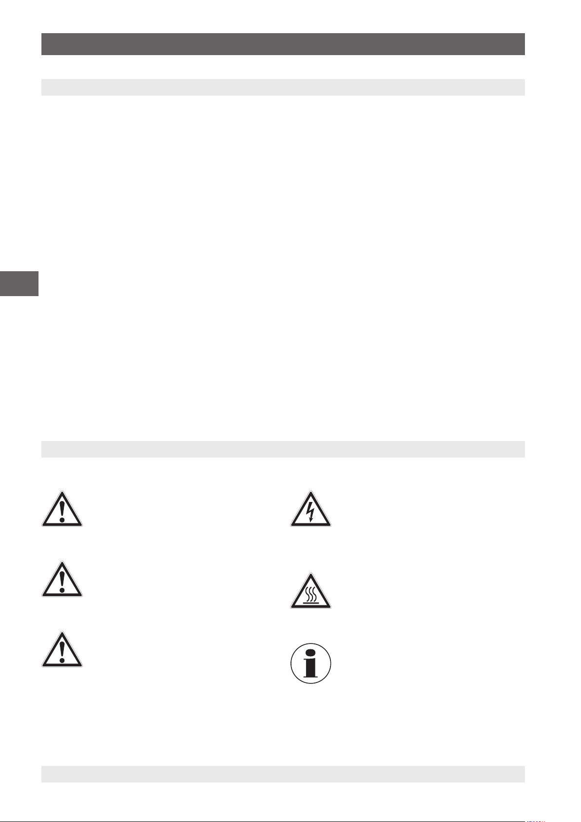
1. Informazioni generali / 2. Sicurezza
1. Informazioni generali
■
Il calibratore di temperatura a secco modello CTD9100ZERO descritto nel presente manuale d'uso è stato
progettato e costruito secondo lo stato dell'arte della
tecnica. Tutti i componenti sono sottoposti a severi
controlli di qualità e ambientali durante la produzione.
I nostri sistemi di qualità sono certificati ISO 9001 e
ISO 14001.
■
Questo manuale d'uso contiene importanti informazioni
sull'uso dello strumento. Lavorare in sicurezza implica il
rispetto delle istruzioni di sicurezza e di funzionamento.
■
Osservare le normative locali in tema di prevenzione
incidenti e le regole di sicurezza generali per il campo
d'impiego dello strumento.
IT
■
Il manuale d'uso è parte dello strumento e deve essere
conservato nelle immediate vicinanze dello stesso e
facilmente accessibile in ogni momento al personale
qualificato. Trasferire le istruzioni d'uso e manutenzione
all'operatore o al possessore successivo.
■
Il manuale d‘uso deve essere letto con attenzione e
compreso dal personale qualificato prima dell‘inizio di
qualsiasi attività.
■
Si applicano le nostre condizioni generali di vendita,
allegate alla conferma d’ordine.
■
Soggetto a modifiche tecniche.
■
Le tarature di fabbrica / DKD/DAkkS/ACCREDIA sono
effettuate secondo gli standard internazionali.
■
Ulteriori informazioni:
- Indirizzo Internet: www.wika.it
- Scheda tecnica prodotto: CT 41.30
- Consulenze tecniche ed
applicative:
Tel.: +39 02 93861-1
Fax: +39 02 93861-74
calibrazione.it@wika.com
2. Sicurezza
2.1 Legenda dei simboli
PERICOLO!
... indica una situazione di potenziale pericolo
che, se non evitata, può causare lesioni gravi o
morte.
ATTENZIONE!
... indica una situazione di potenziale pericolo
che, se non evitata, può causare ferite gravi o
morte.
CAUTELA!
... indica una situazione di potenziale pericolo
che, se non evitata, può causare ferite lievi o
danni alle apparecchiature o all'ambiente.
PERICOLO!
... identifica pericoli causati dalla alimentazione
elettrica. Se non vengono osservate le istruzioni
relative alla sicurezza, c'è il rischio che possano
verificarsi lesioni gravi o morte.
ATTENZIONE!
... indica una situazione di potenziale pericolo
che, se non evitata, può causare ustioni causate
da superfici o liquidi bollenti.
Informazione
... fornisce suggerimenti utili e raccomandazioni
per l'utilizzo efficiente e senza problemi dello
strumento.
76 WIKA manuale d‘uso calibratore di temperatura a secco, modello CTD9100-ZERO
14031673.03 06/2016 EN/DE/FR/ES/IT
Page 77

2. Sicurezza
2.2 Destinazione d'uso
Il calibratore di temperatura a secco modello CTD9100-ZERO
è un'unità portatile, ideato per scopi di assistenza, ma adatto
anche per utilizzo in ambito industriale e di laboratorio. Il
calibratore di temperatura a secco di WIKA è stato progettato
per la taratura di termometri, termoresistenze e termocoppie.
Non è consentito l'utilizzo di questo strumento in aree
pericolose!
Lo strumento è stato progettato e costruito esclusivamente
per la sua destinazione d'uso e può essere impiegato solo
per questa.
Le specifiche tecniche riportate in questo manuale d'uso
devono essere rispettate. L'uso improprio dello strumento al
di fuori delle specifiche tecniche richiede che lo strumento
venga messo immediatamente fuori servizio e che venga
ispezionato da un tecnico di servizio WIKA autorizzato.
Maneggiare gli strumenti di misura di precisione elettronici
con la dovuta cautela (proteggerli da umidità, impatti, forti
campi magnetici, elettricità statica e temperature estreme,
non inserire alcun oggetto nello strumento o nelle sue
aperture). Connettori e prese devono essere protette dalle
contaminazioni.
Se lo strumento viene spostato da un ambiente freddo a
uno caldo, la formazione di condensa può portare a un
malfunzionamento dello strumento. Prima di mettere in
funzione lo strumento, attendere che la temperatura dello
strumento e quella dell'ambiente si equalizzino.
Le istruzioni di sicurezza all'interno di questo manuale d'uso,
così come la sicurezza, la prevenzione degli incidenti e le
normative di tutela ambientale per l'area di applicazione
devono essere rispettati.
L'operatore è obbligato a mantenere sempre perfettamente
leggibile l'etichetta dello strumento.
2.5 Qualificazione del personale
ATTENZIONE!
Rischio di lesioni in caso di personale non
qualificato
L'uso improprio può condurre a lesioni gravi o
danni alle apparecchiature.
▶
Le attività riportate in questo manuale d'uso
possono essere effettuate solo da personale
in possesso delle qualifiche riportate di
seguito.
Personale qualificato
Per personale qualificato, autorizzato dall'operatore, si
intende personale che, sulla base della sua formazione
tecnica, della conoscenza della tecnologia di misura
e controllo e sulla sua esperienza e conoscenza delle
normative specifiche del paese, normative e direttive correnti,
sia in grado di effettuare il lavoro descritto e di riconoscere
autonomamente potenziali pericoli.
Eventuali condizioni operative speciali richiedono inoltre
conoscenze specifiche, es. fluidi aggressivi.
IT
Il costruttore non è responsabile per reclami di qualsiasi
natura in caso di utilizzo dello strumento al di fuori della sua
destinazione d'uso.
2.3 Uso improprio
ATTENZIONE!
Lesioni derivanti da uso improprio
L'uso improprio dello strumento può provocare
situazioni pericolose o lesioni.
▶
Astenersi dall'effettuare modifiche non
autorizzate allo strumento.
▶
Non utilizzare lo strumento all'interno di aree
pericolose.
Qualsiasi utilizzo dello strumento al di fuori o diverso da
quello previsto è considerato uso improprio.
2.4 Responsabilità dell'operatore
Lo strumento è utilizzato nel settore industriale. L'operatore
è quindi responsabile per gli obblighi di legge in materia di
sicurezza sul lavoro.
14031673.03 06/2016 EN/DE/FR/ES/IT
2.6 Dispositivi di protezione personale
I dispositivi protettivi personali sono progettati per proteggere
il personale qualificato da pericoli che possono danneggiare
la sicurezza e la salute durante il lavoro. Nell'esecuzione
delle diverse attività con lo strumento, il personale qualificato
deve indossare i dispositivi di protezione.
Seguire le istruzioni riportate nell'area di lavoro
riguardanti i dispositivi di protezione!
L'attrezzatura necessaria per la protezione individuale deve
essere fornita dall'azienda.
Indossare occhiali protettivi!
Proteggere gli occhi da particelle volatili o
spruzzi di liquidi.
Indossare guanti protettivi!
Proteggere le mani dal contatto con superfici
bollenti e agenti aggressivi.
WIKA manuale d‘uso calibratore di temperatura a secco, modello CTD9100-ZERO 77
Page 78

2. Sicurezza / 3. Esecuzione e funzioni
2.7 Etichettatura, simboli per la sicurezza
Etichetta prodotto (esempio)
Sul retro dello strumento è riportata l'etichetta del prodotto
con informazioni importanti riguardanti il calibratore di
temperatura a secco
Gli strumenti riportanti questo marchio sono in
accordo con le relative Direttive Europee.
Designazione dello strumento
Modello
Anno di produzione
Fusibile
N. di serie
Alimentazione
Campo di temperatura
IT
Simboli
Prima di montare e installare lo strumento,
assicurarsi di avere letto attentamente il
manuale d'uso!
3. Esecuzione e funzioni
3.1 Descrizione
Il calibratore di temperatura a secco modello CTD9100ZERO è un'unità portatile, ideato per scopi di assistenza,
ma adatto anche in ambito industriale e in laboratorio.
Esso è stato progettato per la taratura di termometri,
termoresistenze e termocoppie.
Sono in grado di generare con facilità una temperatura
durevole del giunto freddo, semplificando in questo modo
la taratura delle termocoppie. Si evitano così la complessità
del metodo delle celle d'acqua a punto fisso, il pericolo di
formazione di ghiaccio e i danni di trasporto. Il CTD9100ZERO, come calibratore del punto di congelamento,
consente non solo di raggiungere il punto zero in °C, ma è
anche in grado di effettuare ulteriori temperature di prova,
grazie al raffreddamento attivo.
Grazie alla sua esecuzione e al tipo di unità di controllo, è
possibile ottenere anche una distribuzione della temperatura
all'interno del blocco. Per questo motivo, la temperatura
può essere accettata come omogenea e non come
una distribuzione di uno dei sette fori di prova. Questa
distribuzione omogenea della temperatura riduce l'influenza
sull'incertezza di misura.
In termini di accuratezza di misura, funzionalità e
funzionamento in sicurezza dello strumento, il CTD9100ZERO rappresenta lo stato dell'arte della tecnica. La
posizione di funzionamento è verticale, in quanto questa
posizione consente di ottenere la distribuzione della
temperatura ottimale. La temperatura impostata del blocco
riscaldante è visualizzata tramite un ampio display a LED
a 4 cifre e ad elevato contrasto. Per una facile lettura della
temperatura, il display non è solo ampio, ma è anche
inclinato con un angolo di 35°.
La sicurezza di funzionamento è garantita soltanto se
l'attrezzatura è utilizzata per la rispettiva destinazione d'uso. I
valori limite indicati non devono mai essere superati (vedere
capitolo 10 “Specifiche tecniche“).
14031673.03 06/2016 EN/DE/FR/ES/IT
78 WIKA manuale d‘uso calibratore di temperatura a secco, modello CTD9100-ZERO
Page 79

3. Esecuzione e funzioni
3.2 Scopo di fornitura
Il calibratore di temperatura a secco viene fornito in un
imballo protettivo speciale. L'imballo deve essere conservato,
in modo che il calibratore possa essere restituito in modo
sicuro al costruttore per la ricertificazione o riparazione.
■
Calibratore di temperatura a secco
■
Cavo di alimentazione da 1,5 m (5 ft) con spina di rete
■
Manuale d'uso in lingua italiana e inglese
■
Certificato di taratura 3.1 secondo DIN EN 10204
Controllare lo scopo di fornitura con il documento di
consegna / trasporto.
ATTENZIONE!
Danni dovuti a cavo di alimentazione non
corretto
Se si utilizza un cavo di alimentazione di terzi, è
possibile che si verifichino tensioni non corrette
sullo strumento.
▶
Utilizzare esclusivamente il cavo di
alimentazione fornito in dotazione.
IT
Fig. 1. Calibratore di temperatura a secco
3.3 Panoramica
Il calibratore è composto da una custodia in acciaio robusta,
verniciata di colore grigio e blu e dotata di una maniglia di
trasporto sulla parte superiore.
La parte posteriore della custodia include un blocco in
metallo con sette fori per gli strumenti in prova, accessibili
dall'alto.
Nel blocco in metallo sono installati gli elementi di
riscaldamento o di raffreddamento e la sonda di temperatura
per la determinazione della temperatura di riferimento.
Il blocco in metallo è isolato termicamente.
La parte anteriore della custodia contiene l'unità
elettronica completa per il controllo della temperatura di
riferimento.
Per il controllo degli elementi di riscaldamento e di
raffreddamento vengono utilizzati dei relè a semiconduttore.
Sul pannello anteriore è situato il regolatore, dotato di display
LED a 4 cifre a elevato contrasto, per la temperatura di
riferimento e per quella di prova.
Fig. 2. Blocco di temperatura con sette fori di prova
14031673.03 06/2016 EN/DE/FR/ES/IT
WIKA manuale d‘uso calibratore di temperatura a secco, modello CTD9100-ZERO 79
Page 80

3. Esecuzione e funzioni
3. Esecuzione e funzioni
3.4 Vista isometrica
3
2
IT
1
Blocco di temperatura
1
2
Regolatore
3
Maniglia
4
Etichetta prodotto
5
Interfaccia RS-485
6
Ventolina
7
Connettore C14 con filtro di rete e interruttore On/Off
Lato frontale e superiore
Il regolatore, con display e unità di comando, si trova sul lato
frontale del calibratore.
Nella parte superiore del calibratore di temperatura a
secco si trova il blocco in metallo con sette fori di prova per
l'inserimento degli strumenti in prova.
Lato posteriore dello strumento
Sul lato posteriore dello strumento si trova l'etichetta del
prodotto che contiene informazioni importanti riferite a
4
5
6
7
modello, numero di serie, tensione di rete e portata del
fusibile.
Al di sotto dell'etichetta del prodotto si trova il connettore per
l'interfaccia RS-485.
Fondo dello strumento
Sul fondo dello strumento si trovano il connettore e
l'interruttore di rete con il portafusibile.
Questi si trovano al centro, sul lato frontale. Inoltre, è
presente anche una presa dell'aria e la presa C13 da
pannello per l'alimentazione di tensione operativa.
Non ostruire in alcun modo la presa dell'aria!
80 WIKA manuale d‘uso calibratore di temperatura a secco, modello CTD9100-ZERO
14031673.03 06/2016 EN/DE/FR/ES/IT
Page 81

3. Esecuzione e funzioni
3. Esecuzione e funzioni
3.5 Tasti funzione e LED
Il regolatore del calibratore può essere fatto funzionare facilmente tramite quattro tasti.
1 2
14
13
Fig. 3. Panoramica degli elementi di comando sul lato frontale del regolatore
346 5789101112
Tasti funzione e relativo signicato:
Tasto di richiamo, tasto U (tasto U)
1
Richiama le temperature di prova memorizzate.
Questo tasto può essere assegnato in modo
individuale tramite il parametro “USrb”. Nelle
impostazioni di base, è possibile selezionare le
posizioni di memoria dalla SP1 alla SP4 tenendo
premuto il tasto per più di 1 s.
Tasto di incremento, tasto ▲ (tasto UP)
2
■
Incrementare i valori da impostare
■
Selezionare le singole voci di menu
■
Tornare a un livello di menu precedente
Il tasto è utilizzato per incrementare un valore da
impostare e selezionare i parametri. Se il tasto viene
mantenuto premuto, l'utente viene rimandato a un
livello di menu precedente dove rimane fino a quando
non abbandona il modo di programmazione. Al di fuori
del modo di programmazione, il tasto consente di
visualizzare la potenza di uscita attuale controllata.
Tasto di decremento, tasto ▼ (tasto DOWN)
3
■
Ridurre i valori da impostare
■
Selezionare le singole voci di menu
■
Tornare a un livello di menu precedente
Il tasto è utilizzato per ridurre un valore da impostare
e selezionare i parametri. Se il tasto viene mantenuto
premuto, l'utente viene rimandato a un livello di
menu precedente dove rimane fino a quando non
abbandona il modo di programmazione.
Tasto di programmazione, tasto P (tasto P)
4
■
Accesso al parametro della temperatura di prova
■
Accedere alle voci di menu e ai parametri
■
Confermare il dato immesso
LED lampeggianti e relativo signicato:
LED SET
5
Se lampeggia è possibile accedere al menu di
programma.
LED AL2
6
Uscita allarme (stato) AL2
LED AL1
7
Uscita allarme (stato) AL1
LED + Shift index
8
Il valore di temperatura è maggiore rispetto al valore
impostato nel parametro “AdE”
LED = Shift index
9
Il valore di temperatura è compreso nel range dei
parametri impostati [SP+AdE ... SP-AdE].l
LED – Shift index
10
Il valore di temperatura è minore rispetto al valore
impostato nel parametro “AdE”
LED Cool
11
Il calibratore si sta raffreddando
LED Heat
12
Il calibratore si sta riscaldando
Indicatore della temperatura attuale
13
LED AT/ST
14
La funzione “self-tuning” è stata attivata (acceso) o
la funzione “auto-tuning” è attualmente in funzione
(lampeggiante).
IT
Tramite questo tasto viene confermata una selezione.
Se viene tenuto premuto per più di 5 s si giunge al
livello di programma. È possibile uscire dal livello di
programma in qualsiasi momento tramite il tasto UP.
14031673.03 06/2016 EN/DE/FR/ES/IT
WIKA manuale d‘uso calibratore di temperatura a secco, modello CTD9100-ZERO 81
Page 82

3. Esecuzione e funzioni
3.6 Interfaccia dati
Gli strumenti sono dotati di un'interfaccia di comunicazione
seriale RS-485. Tramite questa interfaccia è possibile
collegarsi a un PC, a un convertitore di livello o a una rete.
Il protocollo software utilizzato è il protocollo MODBUS-RTU,
il quale viene usato in diversi programmi di monitoraggio
disponibili sul mercato.
La velocità di trasmissione (baud rate) è impostata in
fabbrica a 9.600 baud. Su richiesta, sono possibili altre
velocità di trasmissione.
La presa da pannello a 5 pin è dotata di due pin, A e B, che
devono essere collegati ai corrispondenti attacchi sul PC, sul
convertitore di livello o alla rete.
IT
Fig. 4. Vista dall'alto della presa da pannello a 5 pin
3.7 Protocollo di interfaccia
Il protocollo di interfaccia è disponibile su richiesta di
consegna come documento addizionale speciale.
3.8 Monitoraggio del conduttore di protezione
Il calibratore è dotato di un monitoraggio del conduttore
di protezione per controllare l'isolamento di base del
riscaldatore. L'unità di monitoraggio funziona in modo
indipendente dall'unità di controllo normalmente utilizzata
e disattiva l'alimentazione del riscaldamento non appena il
calibratore non è più collegato al sistema del conduttore di
protezione.
Non appena viene ristabilito il collegamento al sistema
del conduttore di protezione, l'unità di monitoraggio
riattiva automaticamente l'alimentazione sul circuito di
riscaldamento.
Per collegarsi al PC, il segnale RS-485 deve essere
convertito esternamente in un segnale RS-232 o in un
segnale USB. Il convertitore adatto, inclusi i driver, è
disponibile come opzione. Il computer registra tutti i dati
operativi e consente la programmazione di tutti i parametri di
configurazione del calibratore.
I requisiti minimi per il funzionamento con un convertitore
USB sono:
■
PC IBM compatibile
■
Sistema operativo installato, Microsoft® Windows® 98
SE, ME, 2000, XP (Home o Prof.) o 7
■
Interfaccia USB (USB 1.1 o USB 2.0)
Una connessione alla rete consente di collegare fino a 32
calibratori/microbagni alla stessa rete.
Per il collegamento a una rete, sono necessarie alcune
impostazioni di fabbrica. A tale scopo, contattare il fornitore o
direttamente WIKA.
In caso di accesso alla programmazione tramite
tastiera mentre è in corso una comunicazione
mediante interfaccia seriale, sullo schermo
appare il messaggio “buSy”, il quale indica lo
stato “occupato”.
82 WIKA manuale d‘uso calibratore di temperatura a secco, modello CTD9100-ZERO
14031673.03 06/2016 EN/DE/FR/ES/IT
Page 83

4. Trasporto, imballaggio e stoccaggio / 5. Messa in servizio, funzionamento
4. Trasporto, imballo e stoccaggio
4.1 Trasporto
Controllare che il calibratore di temperatura a secco modello
CTD9100-ZERO non sia stato danneggiato durante il
trasporto.
Danni evidenti devono essere segnalati tempestivamente.
CAUTELA!
Danni dovuti a trasporto improprio
Con un trasporto non corretto, lo strumento può
subire danni gravi.
▶
Quando le merci imballate si scaricano al
momento della consegna, così come durante
il trasporto interno, procedere con cautela e
osservare i simboli riportati sull'imballo.
▶
In caso di trasporti interni, osservare
le istruzioni riportate nel capitolo
4.2 “Imballaggio e stoccaggio“.
Se lo strumento viene spostato da un ambiente freddo a
uno caldo, la formazione di condensa può portare a un
malfunzionamento dello strumento. Prima di mettere in
funzione lo strumento, attendere che la temperatura dello
strumento e quella dell'ambiente si equalizzino.
4.2 Imballaggio e stoccaggio
Rimuovere l'imballo solo appena prima dell'installazione.
Conservare l'imballo per proteggere lo strumento in
successivi trasporti (es. variazione del sito di installazione,
invio in riparazione).
Condizioni consentite per lo stoccaggio:
■
Temperatura di stoccaggio: 0 ... 60 °C (32 ... 140 °F)
■
Umidità: 35 ... 85 % umidità relativa (senza
condensazione)
Evitare l'esposizione ai seguenti fattori:
■
Esposizione diretta al sole o prossimità con oggetti molto
caldi
■
Vibrazioni e shock meccanici (posare lo strumento in
modo energico)
■
Fuliggine, vapori, polvere e gas corrosivi
■
Ambienti pericolosi, atmosfere infiammabili
Conservare il calibratore di temperatura a secco nel suo
imballo originale in un luogo rispondente alle condizioni
riportate sopra. Se l'imballo originale non è disponibile,
imballare e conservare lo strumento come indicato di seguito:
1. Riporre lo strumento nella scatola con materiale
assorbente gli urti.
2. Se deve essere conservato per un periodo prolungato
(più di 30 giorni), includere una bustina di gel antiumidità
all'interno dell'imballo.
IT
5. Messa in servizio, funzionamento
Personale: personale qualificato
Equipaggiamento protettivo: occhiali protettivi, guanti
protettivi
Utilizzare esclusivamente parti originali (vedere capitolo
11 “Accessori“).
ATTENZIONE!
Lesioni fisiche e danni alle cose e
all'ambiente causati da fluidi pericolosi
A contatto con fluidi pericolosi (ad esempio
ossigeno, acetilene, sostanze infiammabili
o tossiche), con fluidi nocivi (ad esempio
corrosivi, tossici, cancerogeni, radioattivi),
e anche con impianti di refrigerazione e
compressori, vi è il rischio di lesioni fisiche e
danni alle cose e dell'ambiente.
▶
Per questi fluidi, in aggiunta a tutte le
normative standard esistenti, è necessario
seguire appropriati codici o regolamenti.
▶
Indossare l'equipaggiamento di protezione
necessario (vedere capitolo 2.6 “Dispositivi di
14031673.03 06/2016 EN/DE/FR/ES/IT
protezione personale“).
5.1 Posizione di funzionamento
PERICOLO!
Pericolo di morte causato dalla corrente
elettrica
A contatto con le parti in tensione, c'è un
pericolo diretto di morte.
▶
Il funzionamento con un cavo di
alimentazione difettoso (es. in cortocircuito
dalla rete verso l'uscita) può causare tensioni
pericolose allo strumento!
■
La posizione di funzionamento del calibratore di
temperatura a secco presenta un orientamento verticale,
in quanto garantisce una distribuzione della temperatura
ottimale nel blocco in metallo.
■
Posizionare il calibratore di temperatura a secco su una
superficie pulita in modo che il ventilatore sul fondo non
venga bloccato e in modo che possa essere aspirata una
quantità di aria fresca sufficiente.
WIKA manuale d‘uso calibratore di temperatura a secco, modello CTD9100-ZERO 83
Page 84

5. Messa in servizio, funzionamento
Una ventilazione non sufficiente può causare il
danneggiamento del calibratore.
5.2 Accensione del calibratore
1. Collegarsi all'alimentazione di rete utilizzando il cavo di
alimentazione fornito in dotazione.
Collegare lo strumento esclusivamente ai circuiti
dove il rischio di un'interruzione di corrente è
stato ridotto al minimo, in quanto, in caso di
interruzione di corrente, non è più possibile
alimentare aria di raffreddamento.
2. Attivare l'interruttore di rete.
IT
L'interruttore principale si trova sul fondo dello
strumento, al centro, sul davanti. Dopo aver
eseguito un breve auto-test, il regolatore inizia
a regolare la temperatura nel blocco in base
all'ultimo valore impostato.
Dopo il trasporto o lo stoccaggio del calibratore in ambienti
umidi, la temperatura degli elementi di riscaldamento deve
essere aumentata in modo graduale.
5.3 Taratura (modo di taratura)
Non appena il calibratore viene acceso, dopo
l'inizializzazione si trova nel modo di taratura.
Sul display viene visualizzata la temperatura imposata
selezionata.
I segnali LED Heat e LED Cool indicano lo stato dell'uscita
per il controllo del riscaldamento:
■
Se LED Heat è acceso, la temperatura aumenta.
■
Se LED Heat non è acceso, il riscaldamento viene
disattivato.
■
Se LED Cool è acceso, la temperatura diminuisce.
■
Se LED Cool non è acceso, il raffreddamento viene
disattivato.
Il regolatore viene inizializzato.
Il processo di inizializzazione viene completato dopo circa
5 s; dopodiché il modo di calibrazione verrà visualizzato
automaticamente.
A questo punto il display LED a 4 cifre del regolatore
visualizza l'ultima temperatura di prova impostata. Gli
elementi di riscaldamento e di raffreddamento integrati
porteranno automaticamente la temperatura del blocco
in metallo dal valore di temperatura ambiente al valore
impostato.
Non appena viene raggiunta la temperatura impostata,
l'energia di riscaldamento irradiata dal blocco in metallo
viene fornita tramite impulsi brevi, in modo che la
temperatura all'interno rimanga costante.
Fig. 5. Display della temperatura impostata
5.2.1 Procedura di avvio
Se il calibratore non viene utilizzato per un periodo di
tempo prolungato, per via dei materiali utilizzati (ossido di
magnesio) è possibile che penetri umidità negli elementi di
riscaldamento.
LED Heat LED Cool
Fig. 6. Display con LED Heat e LED Cool
Durante la fase di riscaldamento o di raffreddamento,
una luce continua indica l'alimentazione di energia di
riscaldamento o di raffreddamento. Un LED lampeggiante
segnala che la temperatura impostata selezionata è stata
quasi raggiunta e che quindi l'energia di riscaldamento o
di raffreddamento vengono fornite ancora soltanto a brevi
intervalli.
Per assicurare una buona stabilità della temperatura, il tempo
di ciclo del regolatore viene impostato su un valore basso e
l'uscita del regolatore viene attivata spesso.
5.4 Impostazione di una temperatura
A queste condizioni di funzionamento, una temperatura
impostata salvata viene modificata in modo temporaneo.
1. Premere brevemente il tasto P.
Sul display viene visualizzata la temperatura
⇒
impostata attualmente attiva.
2. Premendo il tasto ▲, la temperatura impostata viene
aumentata. Premendo il tasto ▼, la temperatura
impostata viene diminuita.
3. Premendo nuovamente il tasto P, il valore impostato
appena selezionato viene confermato.
14031673.03 06/2016 EN/DE/FR/ES/IT
84 WIKA manuale d‘uso calibratore di temperatura a secco, modello CTD9100-ZERO
Page 85

5. Messa in servizio, funzionamento / 6. Raffreddamento del blocco in ...
5.5 Misurazione o calibrazione di una sonda di
temperatura
1. Tutti i fori nell'inserto devono essere puliti, in stato perfetto
e privi di corpi estranei.
2. Lo strumento in prova e il foro nel blocco devono
combaciare perfettamente in modo che la resistenza alla
trasmissione di calore rimanga il più bassa possibile.
3. Per impostare la temperatura tramite il regolatore, vedere
il capitolo 5.4 “Impostazione di una temperatura“.
4. Se una temperatura impostata è stata regolata, attendere
fino a quando la temperatura viene raggiunta e quindi
attendere per altri 10 minuti per consentire che si imposti
un equilibrio termico.
5. Quindi leggere o misurare lo strumento in prova.
6. Una volta che la misurazione è stata
completata, lasciare raffreddare il calibratore di
temperatura a secco. (vedere anche il capitolo
6 “Raffreddamento del blocco in metallo“)
ATTENZIONE!
Rischio di ustioni!
Prima di rimuovere la sonda di temperatura o lo
strumento in prova, assicurarsi che il calibratore
di temperatura a secco si sia raffreddato a
sufficienza, in quanto, in caso contrario, sussiste
un rischio elevato di scottature sia sul blocco in
metallo sia sullo strumento in prova.
▶
Per far sì che la temperatura del blocco in
metallo possa essere diminuita velocemente,
impostare la temperatura a un valore più
basso (ad es. temperatura ambiente).
▶
Raffreddare lo strumento riscaldato
sempre al di sotto di 50 °C (122 °F) prima
di rimuovere la sonda di temperatura o lo
strumento in prova.
▶
Non lasciare mai uno strumento riscaldato
incustodito.
7. Dopo averlo raffreddato, estrarre la sonda di temperatura
o lo strumento in prova dal blocco in metallo.
5.5.1 Prova di sonde di temperatura
Per effettuare la prova di sonde di temperatura, collegare
uno strumento di misura della temperatura separato allo
strumento in prova. Confrontando la temperatura visualizzata
sullo strumento di misura esterno con la temperatura di
riferimento è possibile definire lo stato dello strumento in
prova. Considerare che lo strumento in prova impiega poco
tempo per raggiungere la temperatura del blocco in metallo.
Non è possibile calibrare termocoppie
collegate a terra, in quanto, considerando che
il blocco riscaldante è collegato a terra, questo
porterebbe a risultati di misura errati.
IT
6. Raffreddamento del blocco in metallo
ATTENZIONE!
Rischio di ustioni!
Prima del trasporto o del contatto con il
blocco in metallo, assicurarsi che il calibratore
di temperatura a secco si sia raffreddato a
sufficienza, in quanto, in caso contrario, sussiste
un rischio elevato di scottature sia sul blocco in
metallo sia sullo strumento in prova.
▶
Per far sì che la temperatura del blocco in
metallo possa essere diminuita velocemente,
impostare la temperatura a un valore più
basso (ad es. temperatura ambiente).
▶
Raffreddare lo strumento riscaldato sempre
al di sotto di 50 °C (122 °F) prima di
disconnetterlo dall'alimentazione di rete o di
spegnerlo, o prima di rimuovere la sonda di
temperatura o lo strumento in prova.
▶
Non lasciare mai uno strumento riscaldato
14031673.03 06/2016 EN/DE/FR/ES/IT
WIKA manuale d‘uso calibratore di temperatura a secco, modello CTD9100-ZERO 85
incustodito.
Nel caso di uno strumento di riscaldamento, il ventilatore
integrato passerà automaticamente a una velocità
superiore, consentendo l'alimentazione di un flusso d'aria di
raffreddamento.
Dopo aver disattivato o rimosso la presa di rete,
il ventilatore integrato non fornirà più aria di
raffreddamento. Ciò nonostante viene garantito
un disaccoppiamento termico adeguato tra il
blocco in metallo e la custodia.
Page 86

7. Malfunzionamenti e guasti
7. Malfunzionamenti e guasti
Personale: personale qualificato
Equipaggiamento protettivo: occhiali protettivi, guanti
protettivi
CAUTELA!
Lesioni fisiche e danni alle cose e
all'ambiente
Se i guasti non possono essere eliminati tramite
le misure elencate, il calibratore di temperatura
a secco modello CTD9100-ZERO deve essere
messo immediatamente fuori servizio.
▶
Assicurarsi che non vi sia più tensione e
proteggerlo dalla riattivazione accidentale.
▶
Contattare il costruttore.
▶
Se è necessario restituire lo strumento,
IT
seguire le istruzioni riportate nel capitolo
9.2 “Resi“.
Per informazioni dettagliate, vedere il capitolo
1 “Informazioni generali“ o il retro del manuale
d'uso.
Errore Cause Rimedi
- - - - Interruzione o guasto del sensore di riferimento
interno
uuuu Temperatura misurata al di sotto del valore limite
del sensore di riferimento interno (underrange
-200 °C (-328 °F)).
oooo Temperatura misurata al di sopra del valore limite
del sensore di riferimento interno (overrange +850
°C (+1,562 °F)).
ErEP Possibile errore nella memoria EEPROM del
regolatore.
Il ventilatore non è in funzione Il ventilatore è guasto o bloccato.
È possibile che l'interruttore di temperatura sia
scattato e che l'alimentazione di corrente agli
elementi di riscaldamento sia stata disattivata.
La temperatura finale non
viene raggiunta
Nessuna visualizzazione Il regolatore è guasto.
Nessuna funzione Il collegamento alla rete non è stato effettuato in
Il relè a semiconduttore è guasto, oppure si
è verificato un cortocircuito dell'elemento di
riscaldamento/raffreddamento o l'elemento di
riscaldamento/raffreddamento è troppo datato.
modo corretto oppure il fusibile è difettoso.
Restituire lo strumento al produttore o al servizio
di assistenza per essere riparato.
Premere il tasto P.
Restituire lo strumento al produttore o al servizio
di assistenza per essere riparato.
Controllare il collegamento alla rete e il fusibile.
Fusibile termico
Per ragioni di sicurezza, il calibratore è
dotato di un fusibile termico a funzionamento
indipendente, il quale disinserisce
l'alimentazione di corrente al sistema di
riscaldamento se la temperatura all'interno
della custodia è troppo elevata. Non appena il
blocco in metallo è stato raffreddato, restituire il
calibratore a WIKA per essere esaminato.
86 WIKA manuale d‘uso calibratore di temperatura a secco, modello CTD9100-ZERO
14031673.03 06/2016 EN/DE/FR/ES/IT
Page 87

8. Manutenzione, pulizia e ricertificazione
8. Manutenzione, pulizia e ricertificazione
Personale: personale qualificato
Equipaggiamento protettivo: occhiali protettivi, guanti
protettivi
Per informazioni dettagliate, vedere il capitolo
1 “Informazioni generali“ o il retro del manuale
d'uso.
8.1 Manutenzione
Il calibratore di temperatura a secco modello CTD9100ZERO è esente da manutenzione.
Le riparazioni devono essere effettuate solo dal costruttore.
Ciò non vale per la sostituzione del fusibile.
Prima di sostituire il fusibile, il calibratore deve essere
disconnesso scollegando il cavo di alimentazione dalla
tensione di rete.
Utilizzare esclusivamente parti originali (vedere capitolo
11 “Accessori“).
8.2 Pulizia
CAUTELA!
Lesioni fisiche e danni alle cose e
all'ambiente
Una pulizia non corretta può provocare lesioni
fisiche e danni alle cose e all'ambiente. I
residui dei fluidi nel calibratore di temperatura
a secco possono causare rischi alle persone,
all'ambiente e alla strumentazione.
▶
Effettuare la pulizia come descritto di seguito.
1. Raffreddare il calibratore come descritto nel capitolo
6 “Raffreddamento del blocco in metallo“.
2. Prima di eseguire la pulizia, spegnere e scollegare il
calibratore dalla rete.
3. Utilizzare i dispositivi di protezione necessari.
4. Pulire lo strumento con un panno umido. Le connessioni
elettriche non devono entrare in contatto con l'umidità!
CAUTELA!
Danni alle cose
Una pulizia non corretta può causare danni allo
strumento!
▶
Non usare detergenti aggressivi.
▶
Per la pulizia non utilizzare oggetti appuntiti
o duri.
8.2.1 Pulizia del blocco in metallo
In caso di calibratori, durante il funzionamento si forma
una quantità minima di polvere metallica che può causare
l'arresto del blocco e dello strumento in prova. Per prevenire
questa eventualità, effettuare regolarmente, e prima
che il calibratore rimanga inutilizzato per un periodo di
tempo prolungato, uno spurgo dei fori di prova tramite aria
compressa.
8.2.2 Pulizia delle griglie dei ventilatori
Sul fondo di ogni calibratore è presente una fitta griglia
per l'aria attraverso la quale l'aria di raffreddamento viene
alimentata al calibratore. A seconda del livello di pulizia
dell'aria, pulire la griglia a intervalli regolari utilizzando
aspiratori o spazzole.
IT
8.2.3 Pulizia esterna
Pulire l'esterno del calibratore con un panno umido e un po'
d'acqua, o utilizzando un detergente delicato privo di solventi.
8.3 Ricertificazione
Certificato DKD/DAkkS/ACCREDIA - certificati emessi
da enti ufficiali:
Il calibratore di temperatura a secco è stato regolato e
testato prima della consegna utilizzando dispositivi di misura
riconducibili a standard nazionali riconosciuti.
In base alla norma DIN ISO 10012, a seconda
dell'applicazione, il calibratore deve essere verificato a
intervalli periodici adeguati.
Si consiglia di far ricertificare regolarmente lo strumento dal
costruttore a intervalli di circa 12 mesi o di circa 500 ore di
funzionamento.
Inoltre, ogni ricertificazione in fabbrica include anche un
controllo gratuito di tutti i parametri di sistema in base alla
loro conformità alle specifiche. Le impostazioni base saranno
corrette se necessario.
Il principio di base per la ricertificazione è costituito dalle
linee guida dell'istituto tedesco di calibrazione, DKD R5-4.
Per la ricertificazione vengono utilizzate e seguite le misure
descritte in questa sede.
5. Lavare o pulire il calibratore di temperatura a secco,
allo scopo di proteggere le persone e l'ambiente
dall'esposizione con i fluidi residui.
14031673.03 06/2016 EN/DE/FR/ES/IT
WIKA manuale d‘uso calibratore di temperatura a secco, modello CTD9100-ZERO 87
Page 88

Contenuti
9. Messa fuori servizio, resi e smaltimento
Personale: personale qualificato
Equipaggiamento protettivo: occhiali protettivi, guanti
protettivi
ATTENZIONE!
Lesioni fisiche e danni alle cose e
all'ambiente a causa di fluidi residui
I fluidi residui nel calibratore di temperatura a
secco possono causare rischi alle persone,
all'ambiente e alla strumentazione.
▶
Indossare l'equipaggiamento di protezione
necessario (vedere capitolo 2.6 “Dispositivi di
protezione personale“).
▶
Osservare le informazioni contenute nella
scheda di sicurezza per il corrispondente
IT
9.1 Messa fuori servizio
1. Raffreddare il calibratore come descritto nel capitolo
6 “Raffreddamento del blocco in metallo“.
2. Spegnere e scollegare il calibratore dalla rete.
fluido.
▶
Lavare o pulire lo strumento smontato, allo
scopo di proteggere le persone e l'ambiente
dall'esposizione con i fluidi residui.
ATTENZIONE!
Rischio di ustioni
Durante la messa fuori servizio sussiste il
pericolo di fuoriuscita di fluidi bollenti.
▶
Lasciare raffreddare sufficientemente lo
strumento prima di metterlo fuori servizio!
9.2 Resi
Osservare attentamente lo seguenti indicazioni per la
spedizione dello strumento:
Tutti gli strumenti inviati a WIKA devono essere privi di
qualsiasi tipo di sostanze pericolose (acidi, basi, soluzioni,
ecc.) e pertanto devono essere puliti prima di essere restituiti.
ATTENZIONE!
Lesioni fisiche e danni alle cose e
all'ambiente a causa di fluidi residui
I fluidi residui nel calibratore di temperatura a
secco possono causare rischi alle persone,
all'ambiente e alla strumentazione.
▶
In caso di sostanze pericolose, è inclusa la
scheda di sicurezza del materiale per il fluido
corrispondente.
▶
Pulire lo strumento, vedere capitolo
8.2 “Pulizia“.
In caso di restituzione dello strumento, utilizzare l'imballo
originale o utilizzare un contenitore di trasporto adeguato.
Per evitare danni:
1. Riporre lo strumento nella scatola con materiale
assorbente gli urti. Posizionare materiale per assorbire gli
urti su tutti i lati all'interno dell'imballo.
2. Se possibile, includere una bustina di gel anti-umidità
all'interno dell'imballo.
3. Etichettare la spedizione come trasporto di uno
strumento altamente sensibile.
PERICOLO!
Pericolo di morte causato dalla corrente
elettrica
A contatto con le parti in tensione, c'è un
pericolo diretto di morte.
▶
Lo smontaggio dello strumento può essere
effettuato solo da personale qualificato.
▶
Scollegare le attrezzature di prova e di
calibrazione solo dopo aver isolato il sistema
dalle fonti di alimentazione.
ATTENZIONE!
Lesioni fisiche
Durante la messa fuori servizio sussiste un
pericolo dovuto a fluidi aggressivi.
▶
Indossare l'equipaggiamento di protezione
necessario (vedere capitolo 2.6 “Dispositivi di
protezione personale“).
▶
Osservare le informazioni contenute nella
scheda di sicurezza per il corrispondente
fluido.
Le informazioni sulle modalità di gestione resi
sono disponibili nella sezione “Servizi” del
nostro sito web.
9.3 Smaltimento
Lo smaltimento inappropriato può provocare rischi per
l'ambiente.
Lo smaltimento dei componenti dello strumento e dei
materiali di imballaggio deve essere effettuato in modo
compatibile ed in accordo alle normative nazionali.
Questo marchio sugli strumenti indica che essi
non devono essere smaltiti insieme ai normali
rifiuti domestici. Lo smaltimento deve essere
effettuato inviando lo strumento direttamente al
costruttore o tramite le autorità municipali locali
(vedere la direttiva UE 2012/19/UE).
14031673.03 06/2016 EN/DE/FR/ES/IT
88 WIKA manuale d‘uso calibratore di temperatura a secco, modello CTD9100-ZERO
Page 89

10. Specifiche tecniche
10. Specifiche tecniche
Specifiche tecniche CTD9100-ZERO
Display
Campo di temperatura -10 … 0 … +100 °C (14 ... 32 ... 212 °F)
Accuratezza
Stabilità
Risoluzione 0,1 °C
Distribuzione della temperatura
Omogeneità assiale
Controllo di temperatura
Tempo di riscaldamento 15 min da -10 °C a +100 °C (da 14 °F a 212 °F)
Tempo di raffreddamento 5 min da 23 °C a 0 °C (da 73,4 °F a 14 °F)
Tempo di stabilizzazione
Blocco in metallo
Profondità di immersione 150 mm (5,91 in)
Fori di prova 7 fori con Ø 6,5 mm (0,26 pollici)
Materiale blocco Alluminio
Tensione di alimentazione
Alimentazione
Potenza assorbita 225 VA
Cavo di alimentazione per l'Europa, 230 Vca
Fusibile 3,15 A ritardato (a 250 Vca)
Comunicazione
Interfaccia RS-485
Custodia
Dimensioni (L x P x A) 160 x 320 x 320+50 mm (6,3 x 9,1 x 12,6+2 pollici)
Peso 7 kg (15,5 lbs)
1) Da intendersi come la deviazione di temperatura tra il valore misurato e il valore di riferimento.
2) Massima differenza di temperatura ad una temperatura stabile per un periodo di 30 minuti.
3) Il gradiente va inteso come la variazione di temperatura nel foro di prova oltre i primi 40 mm dalla base dell'inserto.
4) Tempo necessario prima di raggiungere un valore di misura stabile.
5) L'alimentazione 115 Vca va specificata sull'ordine, altrimenti viene fornita una 230 Vca.
1)
2)
3)
4)
5)
0,05 K a 0 °C (32 °F), altrimenti 0,1 K
< 0,05 K
< 0,05 K
10 min da 100 °C a 0 °C (da 212 °F a 14 °F)
A seconda dell'uso e del campo di applicazione
100 ... 240 Vca, 50/60 Hz
IT
L'incertezza di misura viene definita come l'incertezza di misura totale (k = 2), la quale comprende i seguenti valori:
accuratezza, incertezza di misura del campione, stabilità e omogeneità.
14031673.03 06/2016 EN/DE/FR/ES/IT
WIKA manuale d‘uso calibratore di temperatura a secco, modello CTD9100-ZERO 89
Page 90

10. Specifiche tecniche / 11. Accessori
Omologazioni
Logo Description Country
Dichiarazione conformità UE
■
Direttiva EMC
EN 61326, (gruppo 1, classe B) emissioni e immunità alle interferenze (applicazione
industriale)
■
Direttiva bassa tensione
EN 61010, requisiti di sicurezza per equipaggiamento elettrico per applicazioni di
misurazione, controllo e laboratorio
EAC
■
Compatibilità elettromagnetica
■
Direttiva bassa tensione
GOST
Tecnologia di misurazione/metrologia
KazInMetr
Tecnologia di misurazione/metrologia
- MTSCHS
IT
Permission for commissioning
BelGIM
Tecnologia di misurazione/metrologia
Uzstandard
Metrology, measurement technology
European Community
Comunità economica
eurasiatica
Russia
Kazakhstan
Kazakhstan
Belarus
Uzbekistan
Certificati
Certificato
Taratura Standard: rapporto di prova 3.1 secondo DIN EN 10204
Opzione: certificato di taratura DKD/DAkkS
Ciclo di ricertificazione consigliato 1 anno (a seconda delle condizioni d'uso)
Per le omologazioni e i certificati, consultare il sito internet
Per ulteriori informazioni tecniche, fare riferimento alla scheda tecnica WIKA CT 41.30 e ai documenti d'ordine.
11. Accessori
Variante dello strumento
■
Lettura in Fahrenheit °F
Taratura
■
Certificato di taratura DKD/DAkkS solo sul punto zero
Cavo di alimentazione
■
Cavo di alimentazione per la Svizzera
■
Cavo di alimentazione per gli USA/Canada
■
Cavo di alimentazione per il Regno Unito
Valigetta di trasporto
■
Valigetta di trasporto senza rotelle
■
Valigetta di trasporto con rotelle
E' possibile trovare gli accessori WIKA online sul sito
www.wika.it.
90 WIKA manuale d‘uso calibratore di temperatura a secco, modello CTD9100-ZERO
14031673.03 06/2016 EN/DE/FR/ES/IT
Page 91

IT
14031673.03 06/2016 EN/DE/FR/ES/IT
WIKA manuale d‘uso calibratore di temperatura a secco, modello CTD9100-ZERO 91
Page 92

WIKA subsidiaries worldwide can be found online at www.wika.com.
WIKA-Niederlassungen weltweit finden Sie online unter www.wika.de.
La liste des filiales WIKA dans le monde se trouve sur www.wika.fr.
Sucursales WIKA en todo el mundo puede encontrar en www.wika.es.
Per le filiali WIKA nel mondo, visitate il nostro sito www.wika.it.
WIKA Alexander Wiegand SE & Co. KG
Alexander-Wiegand-Straße 30
63911 Klingenberg • Germany
Tel. +49 9372 132-0
Fax +49 9372 132-406
info@wika.de
www.wika.de
92 WIKA operating instructions temperature dry well calibrator, model CTD9100-ZERO
14031673.03 06/2016 EN/DE/FR/ES/IT
 Loading...