

Page 1

Operating Instructions
Temperature Indicating Controller, Model CS4R
WIKA Operating Instructions CS4R V1.2 • 05/2006
WIKA Alexander Wiegand GmbH & Co. KG
Alexander-Wiegand-Straße 30
63911 Klingenberg/Germany
Phone (+49) 93 72/132-0
Fax (+49) 93 72/132-406
E-Mail info@wika.de
www.wika.de
Page 2

Operating Instructions Temperature Indicating Controller CS4R
Preface
Thank you for the purchase of our microcomputer based temperature indicating controller CS4R.
This manual contains instructions for the mounting, functions, operations and notes when operating the CS4R.
For model confirmation and unit specifications, please read this manual carefully before starting operation.
To prevent accidents arising from the misuse of this controller, please ensure the operator using it
receives this manual.
Caution
• This instrument should be used according to the specifications described in the manual.
If it is not used according to the specifications, it may malfunction or cause fire.
• Be sure to follow the warnings, cautions and notices. If not, it could cause serious injury or malfunction.
• Specifications of the CS4R and the contents of this instruction manual are subject to change without notice.
• Care has been taken to assure, that the contents of this instruction manual are correct, but if there are any
doubts, mistakes or questions, please inform our sales department.
• This instrument is designed to be installed in a control panel. If not, measures must be taken to ensure that the
operator cannot touch power terminals or other high voltage sections.
• Any unauthorized transfer or copying of this document, in part or in whole, is prohibited.
• WIKA is not liable for any damages or secondary damages incurred as a result of using this product, including
any indirect damages.
SAFETY PRECAUTIONS
(Be sure to read these precautions before using our products.)
The safety precautions are classified into categories: “ Warning” and “ Caution”.
Depending on circumstances, procedures indicated by
to follow the directions for usage.
Caution may be linked to serious results, so be sure
Warning
Procedures which may lead to dangerous conditions and cause death or serious injury, if not carried out
properly.
Caution
Procedures which may lead to dangerous conditions and cause superficial to medium injury or physical
damage or may degrade or damage the product, if not carried out properly.
V1.2 • 05/2006 - 2 -
Page 3

Operating Instructions Temperature Indicating Controller CS4R
List of contents
1. Model name and order code......................................................................................................... 4
2. Name and functions of the sections............................................................................................ 5
3. Mounting to the control panel ...................................................................................................... 5
3.1 Site selection............................................................................................................................. 5
3.2 External dimension ................................................................................................................... 6
3.3 CT (current transformer) external dimension............................................................................ 6
3.4 Mounting to DIN rail .................................................................................................................. 6
4. Wiring connection.......................................................................................................................... 7
5. Setup ............................................................................................................................................... 9
5.1 Operation flow chart .................................................................................................................. 10
5.2 Main setting mode..................................................................................................................... 11
5.3 Sub setting mode ...................................................................................................................... 11
5.4 Auxiliary function setting mode 1 .............................................................................................. 12
5.5 Auxiliary function setting mode 2 .............................................................................................. 14
5.6 Control output manipulated variable indication......................................................................... 17
6. Converter function......................................................................................................................... 18
7. Running........................................................................................................................................... 19
8. Action explanations....................................................................................................................... 19
8.1 OUT action................................................................................................................................ 19
8.2 OUT ON/OFF action ................................................................................................................. 20
8.3 Event (Alarm) action ................................................................................................................. 21
8.4 Event (Heater burnout Alarm) action ........................................................................................ 21
9. PID auto-tuning of the CS4R......................................................................................................... 22
10. Specifications................................................................................................................................. 23
10.1 Standard specifications ........................................................................................................... 23
10.2 Optional specifications ............................................................................................................ 27
11. Troubleshooting............................................................................................................................. 28
11.1 Indication................................................................................................................................. 28
11.2 Key operation .......................................................................................................................... 29
11.3 Control..................................................................................................................................... 29
12. Character table............................................................................................................................... 30
V1.2 • 05/2006 - 3 -
Page 4

Operating Instructions Temperature Indicating Controller CS4R
1. Model Name and Order Code
CS4R - 3 E - / M - - - Series name: CS4R
Control action 3 PID
Alarm output 1 E alarm action is selectable by key operation
relay
R
Control output
Multi-function input
Power supply
Digital interface
logic level DC 0/12 V for solid state relay
S
analogue current signal (4 ... 20 mA)
A
M settable input configuration
H AC 100 ... 240 V, 50 ... 60 Hz
L AC/DC 24 V
without
Z
RS485
5
ZZZ without
W10 single phase system (max. 5 A)
Heater burnout Alarm
W11 single phase system (max. 10 A)
W12 single phase system (max. 20 A)
W15 single phase system (max. 50 A)
Necessary accessory for current input
Instrument configuration
Additional order info
Z without
R shunt resistor 50 Ω
B factory adjustment
K to customer specification
Z without
T additional text
(1) PID, PI, PD, P and ON/OFF action are programmable.
(2) Alarm action (9 types and no alarm) and Energized/Deenergized are selectable by key operation.
(3) The controller with control output analogue current signal (4 … 20 mA) can be configured for use as
temperature transmitter.
(4) Thermocouple, RTD, DC current and DC voltage are selectable by key operation.
(1)
(4)
(3)
(2)
V1.2 • 05/2006 - 4 -
Page 5
Operating Instructions Temperature Indicating Controller CS4R
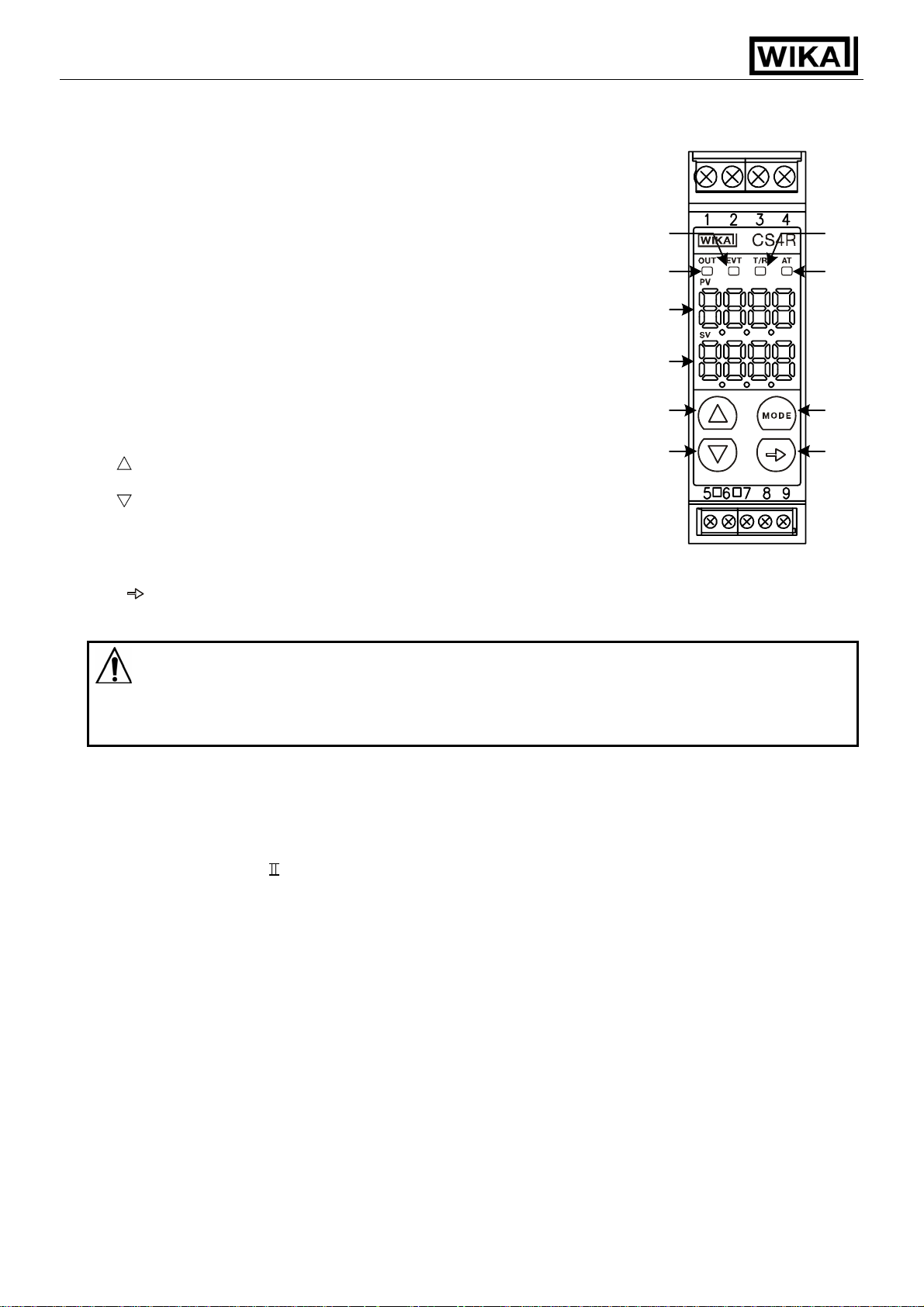
2. Name and functions of the sections
(1) EVT EVT indicator
A red LED lights up when Event output (Alarm, Loop break
alarm or the option Heater burnout alarm) is ON.
(2) OUT OUT indicator
A green LED lights up when OUT output is ON.
For DC current output type, this blinks in a 0.25 second cycle
corresponding to the output manipulated variable .
(3) T/R T/R indicator
A yellow LED blinks during serial communication TX output
(transmission)
(4) AT Auto tuning indicator
A yellow LED blinks while PID auto-tuning is being performed.
(5) PV PV display
Indicates the input value (PV) with a red LED.
(6) SV SV display
Indicates the setting value (SV) with a green LED.
Increase-key
(7)
Increases the numeric value.
Decrease-key
(8)
Decreases the numeric value.
MODE MODE–key
(9)
Changes the setting mode or registers the setting value.
(Resisters the setting value by pressing the MODE-key.) (FIG. 2-1)
(10)
Submode-key]
Brings up Auxiliary function setting mode 2 in combination with the mode key.
(1)
(2)
(5)
(6)
(7)
(8)
(3)
(4)
(9)
(10)
Caution
When setting the specifications and functions of this controller, connect the terminals 1 and 2 for power
source first, then set them referring to “5. Setup” before performing “3. Mounting”
and “4. Wiring”.
3. Mounting
3.1 Site selection
This instrument is intended to be used under the following environmental conditions (IEC61010-1):
Overvoltage category
Mount the controller in a place with:
• A minimum of dust, and an absence of corrosive gases
• No flammable, explosive gasses
• Few mechanical vibrations or shocks
• No exposure to direct sunlight, an ambient temperature of 0 … 50°C (32 … 122°F) without rapid change
• An ambient non-condensing humidity of 35 … 85%RH
• No large capacity electromagnetic switches or cables through which large current is flowing
• No water, oil or chemicals or where the vapors of these substances can come into direct contact with the
controller
, Pollution degree 2
V1.2 • 05/2006 - 5 -
Page 6

Operating Instructions Temperature Indicating Controller CS4R
3.2 External dimensions
75
22.5
(Fig. 3.2-1)
3.3 CT (current transformer) external dimensions
CTL-6S (for 20A) CTL-12-S36-10L1 (for 50A)
(Fig. 3.3-1)
3.4 Mounting to DIN rail
97
100
DIN rail
4
Caution
Mount the DIN rail horizontally.
When DIN rail is mounted vertically, be sure to use commercially available fastening plates at
the end of CS4R series.
Mount the CS4R series to the DIN rail so that the CS4R series may be fixed.
However, if the DIN rail is mounted horizontally in a position susceptible to vibration or
shock, the fastening plates must be used as well.
V1.2 • 05/2006 - 6 -
Page 7

Operating Instructions Temperature Indicating Controller CS4R
1
Hook 1 of the CS4R on the upper side of the DIN rail. (Fig. 3.4-1)
2
Making 1 part of the CS4R as a support, fit the lower part of the CS4R to the DIN rail.
CS4R will be completely fixed to DIN rail with a “Click” sound. (Fig.3.4-1)
(Fig. 3.4-1)
4. Wiring connection
(2)
(1)
Warning
Turn the power supplied to the instrument OFF before wiring or checking it.
Working or touching the terminal with the power switched ON may result in Electric
Shock causing severe injury or death.
Caution
• Do not leave wire chips into the CS4R when wiring, because they could cause fire, malfunction
and trouble.
• Insert the connecting cable into the designated connector securely. Not doing so could cause
malfunction due to imperfect contact.
• Connect the AC power to the designated terminal as is written in this instruction manual.
Otherwise it may burn and damage the CS4R.
• Do not apply a commercial power source to the sensor connected to the input terminal nor allow
the power source to come into contact with the sensor.
• When using a 24V AC/DC for the power source, do not confuse the polarity when it is DC.
• This unit does not have built-in power switch, circuit breaker or fuse. Therfore it is necessary to
install them in the circuit near the external unit.
(Recommended fuse: Time-lag fuse, Rated voltage 250V AC, Rated current 2A)
• Tighten the terminal scre w with the specified torque. Excessive force could damage the terminal
screw and deform the case.
• Use a thermocouple and compensating lead wire that corresponds to the sensor input specification of
this unit.
• Use the 3-wire RTD that corresponds to the sensor input specification of this unit.
• When using DC voltage and current inputs, be careful not to confuse the polarity when wiring.
• Keep input wires (Thermocouple, RTD, etc.) away from power source and load wires when wiring.
V1.2 • 05/2006 - 7 -
Page 8

Operating Instructions Temperature Indicating Controller CS4R
• Note
Tighten the terminal screw properly referring to the table below.
Terminal screw Terminal No. Torque
M2.6 1 to 4 Max. 0.5 Nm
Terminal arrangement
M2.0 5 to 9 Max. 0.25 Nm
POWER SUPPLY
24V AC/DC
Lower part of main body
POWER SUPPLY
100 to 240V AC
MAIN OUTPUT
3A
250V AC
0.1A
24V DC
Communication
(RS-485)
CT input
(Fig. 4-1)
TC
RTD
DC V
DC mA
50Ω
EVENT
OUTPUT
(shunt resistor)
RS-485
No.1
No.6
No.1
No.6
No.1
No.2
No.3
No.4
No.5
No.6
COM
NC
YB(+)
YA(-)
NC
COM
• MAIN OUTPUT : Control output
• EVENT OUTPUT : Outputs when Alarm, Loop break alarm or Heater burnout alarm (option) is ON.
• RS-485 : Serial communication
• TC : Thermocouple
• RTD : Resistance temperature detector
• DC : DC current (DC mA) or DC voltage (DC V)
• Shunt resistor : Shunt resistor 5
0Ω for input signal DC current
• Option: Heater burnout Alarm
(1) This alarm is not available for detecting current
under phase control.
(2) Use the current transformer (CT) provided, and pass a
CT
CT input socket
Power
supply
lead wire of the heater circuit into a hole of the CT.
(3)When wiring, keep the CT wire away from any AC source
or load wires to avoid the external interference.
Heater
(Fig. 4-2)
V1.2 • 05/2006 - 8 -
Page 9

Operating Instructions Temperature Indicating Controller CS4R
5. Setup
The sensor input character and temperature unit are indicated on the PV display for approx. 3 seconds after
the power is turned on, and the input range high limit value is indicated on the SV display. (Table 5-1)
(If any other value is set during the Scaling high limit setting, it is indicated on the SV display.)
During this time all outputs and the LED indicators are in OFF status. After that the control starts indicating
actual temperature on the PV display and setting value on the SV display.
(Table 5-1)
Input Scale range Resolution
K
J –200 ...1000 °C –320 ...1800 °F 1°C (°F)
R
S 0 ... 1760 °C 0 ... 3200 °F 1°C (°F)
B 0 ... 1820 °C 0 ... 3300 °F 1°C (°F)
E –200 ... 800 °C –320 ... 1500 °F 1°C (°F)
T –199.9 ... 400.0 °C –199.9 ... 750.0 °F 0.1°C (°F)
N –200 ... 1300 °C –320 ... 2300 °F 1°C (°F)
PL- 0 ... 1390 °C 0 ... 2500 °F 1°C (°F)
C (W/Re5-26) 0 ... 2315 °C 0 ... 4200 °F 1°C (°F)
Pt100
JPt100
4 ... 20mA DC
0 ... 20mA DC
0 ... 1V DC –1999 ... 9999 *1 1
0 ... 5V DC
1 ... 5V DC –1999 ... 9999 *1 1
0 ... 10V DC –1999 ... 9999 *1 1
*1: Input range and decimal point place can be changed.
*2: 50Ω shunt resistor (sold optionally) must be connected between the input terminals.
–200 ... 1370 °C –320 ... 2500 °F 1°C (°F)
–199.9 ... 400.0 °C –199.9 ... 750.0 °F 0.1°C (°F)
0 ... 1760 °C 0 ... 3200 °F 1°C (°F)
–199.9 ... 850.0 °C –199.9 ... 999.9 °F 0.1°C (°F)
–200 ... 850 °C –300 ... 1500 °F 1°C (°F)
–199.9 ... 500.0 °C –199.9 ... 900.0 °F 0.1°C (°F)
–200 ... 500 °C –300 ... 900 °F 1°C (°F)
–1999 ... 9999 *1, *2 1
–1999 ... 9999 *1, *2 1
–1999 ... 9999 *1 1
V1.2 • 05/2006 - 9 -
Page 10

Operating Instructions Temperature Indicating Controller CS4R
pp
5.1 Operation flow chart
PV/SV display mode
MODE
[Main setting mode] [Sub setting mode] [Auxiliary function setting mode 1] [Auxiliary function setting mode 2]
Set value
[
]
MODE MODE MODE MODE
OUT Proportional band setting
MODE MODE MODE
Integral time
MODE MODE MODE
Derivate time setting
MODE MODE MODE
ARW Anti-reset windup setting
MODE MODE
Out Proportional cycle setting
MODE MODE
Manual reset setting
MODE MODE
Alarm setting
MODE MODE
Heater burnout alarm setting
MODE MODE
Loop break alarm action time
MODE MODE
Loop break alarm action span
MODE MODE
Alarm hysteresis setting
SVTC bias setting
Controller/Converter function
Output status selection when
•
+ MODE: Press the MODE key while the key is being pressed.
+ MODE (Approx. 3s): Press the MODE key while the key is being pressed.
•
•
+ MODE (Approx. 3s): Press the MODE key while the key is being pressed.
For setting and selecting in each setting mode press
V1.2 • 05/2006 - 10 -
MODE (Approx. 3s)
+ MODE + MODE (Approx. 3s) + MODE (Approx. 3s)
PID auto-tuning Perform/Cancel
setting [
setting [
MODE MODE
selection [
MODE MODE
input burnout [
MODE MODE
Control output manipulated
variable indication
Setting value lock selection
[ ]
Sensor correction setting
[
]
Communication protocol
[
]
Instrument number setting
]
[
Data transfer rate selection
[
]
Parity selection
[
]
Stop bit selection
[
[
]
[
]
[
]
]
]
]
]
]
or key.
Control output ON/OFF action
Alarm action selection
Alarm action Energized/
Alarm HOLD function selection
Alarm action delayed timer
Direct/Reverse action selection
AT bias setting
MODE
[ ]
[ ]
sele ction [ ]
[ ]
[ ]
[ ]
[ ]
Dotted lines show options, which are
indicated only when the options are
a
Input type selection
Scaling high limit setting
Scaling low limit setting
Decimal point place selection
PV filter time constant setting
Control output high limit setting
Control output low limit setting
hysteresis [ ]
Deenergized [ ]
MODE
setting [ ]
lied.
[ ]
[ ]
[ ]
[ ]
[ ]
[ ]
[ ]
[ ]
[ ]
[
[ ]
[ ]
]
Page 11

Operating Instructions Temperature Indicating Controller CS4R
5.2 Main setting mode
Character Name, Description, Setting range Default value
SV
• Sets the value for controlled object.
• Scaling low limit value to scaling high limit value
(For DC voltage and current inputs, the placement of the decimal
point follows the selection)
5.3 Sub setting mode
Character Name, Description, Setting range Default value
AT setting
Performs PID auto-tuning. However, when PID auto-tuning does
•
not finish after 4 hours, PID auto-tuning is shut down compulsory.
• PID auto-tuning cancellation :
PID auto-tuning performance :
OUT proportional band setting
• Sets the proportional band.
• The control action becomes ON/OFF when set to 0.0
• Setting range: 0.0 … 110.0%
Integral time setting
• Sets the integral time.
• Setting the value to 0 disables this function.
• Not available for ON/OFF action.
• Setting range: 0 … 1000 seconds
Derivative time setting
• Sets the derivative time.
• Setting the value to 0 disables this function.
• Not available for ON/OFF action.
• Setting range: 0 … 300 seconds
Anti-reset windup setting
• Sets anti-reset windup.
• Setting the value to 0 disables this function.
• Available only for PID action.
• Setting range: 0 … 100%
OUT proportional cycle setting
• Sets the proportional cycle value for the control output (OUT).
• Not available for ON/OFF action or control output analogue
current signal (4 ... 20 mA).
• Setting range: 1 … 120 seconds
Manual reset setting
• Sets the reset value manually.
• Available only for P and PD action.
• ± Proportional band converted value
(For DC voltage and current inputs, the placement of the
decimal point follows the selection)
Alarm setting
• Sets the action point for the alarm output.
• Setting the value to 0 or 0.0 disables this function
(excluding Process high and Process low alarms).
When Loop break alarm and Heater burnout alarm are applied
together, the output is common.
• Not available when “No alarm action” is selected in Alarm
action selection.
• See (Table 5.3-1). (For DC voltage and DC current inputs, the
placement of the decimal point follows the selection.)
0°C
2.5%
200 seconds
50 seconds
50%
30 seconds
or 3 seconds
0.0
0°C
V1.2 • 05/2006 - 11 -
Page 12
Operating Instructions Temperature Indicating Controller CS4R
.
and
XX.X are
indicated in
turn.
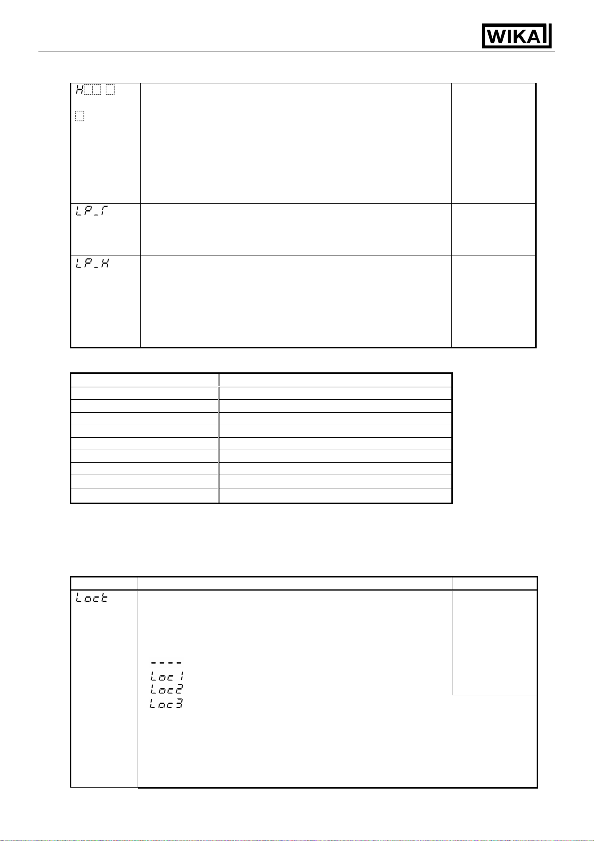
Heater burnout alarm setting
• Sets the heater current value for Heater burnout alarm.
• Setting the value to 0.0 disables this function.
• Self-holding is not available for the alarm output.
• Available only when Heater burnout alarm is added.
• Rating:
5A [W10] : 0.0 ... 5.0A
10A [W11] : 0.0 ...10.0A
20A [W12] : 0.0 ... 20.0A
50A [W15] : 0.0 ... 50.0A
Loop break alarm action time setting
• Sets the action time to assess the Loop break alarm.
• Setting the value to 0 disables this function.
• Setting range: 0 … 200 minutes
Loop break alarm action span setting
• Sets the action span to assess the Loop break alarm.
• Setting the value to 0 disables this function.
• Thermocouple, RTD inputs:
0 … 150°C (°F) or 0.0 … 150.0°C (°F)
DC voltage and current inputs: 0 … 1500
(The placement of the decimal point follows the selection)
(Table 5.3-1)
Alarm action type Setting range
High limit alarm –(Scaling span) to scaling span
Low limit alarm –(Scaling span) to scaling span
High/Low limits alarm 0 to scaling span
High/Low limit range alarm 0 to scaling span
Process high alarm Scaling low limit value to scaling high limit value
Process low alarm Scaling low limit value to scaling high limit value
High limit alarm with standby –(Scaling span) to scaling span
Low limit alarm with standby –(Scaling span) to scaling span
High/Low limits with standby 0 to scaling span
0.0A
0 minutes
0°C
Minimum
negative
setting value:
–199.9 … –1999
Maximum
positive
setting value:
999.9 … 9999
5.4 Auxiliary function setting mode 1
Character Name, Description, Setting range Default value
Setting value Lock selection
• Locks the setting value to prevent setting errors.
The setting item to be locked is dependent on the designation.
• PID auto-tuning cannot be carried out when Lock1 or Lock2
is selected.
•
(Unlock) : All setting values can be changed.
(Lock 1) : None of setting values can be changed.
(Lock 2) : Only main setting mode can be changed.
(Lock 3) : All setting values can be changed except Controller/Converter
Unlock
function selection. However, do not change each setting item of
Auxiliary function setting mode 2.
Changed data reverts to their former value after power is turned
off because they are not saved in the non-volatile memory. Lock
3 is suitable when our programmable controller (with SVTC) is
used together because it has noting to do with memory life.
V1.2 • 05/2006 - 12 -
Page 13
Operating Instructions Temperature Indicating Controller CS4R
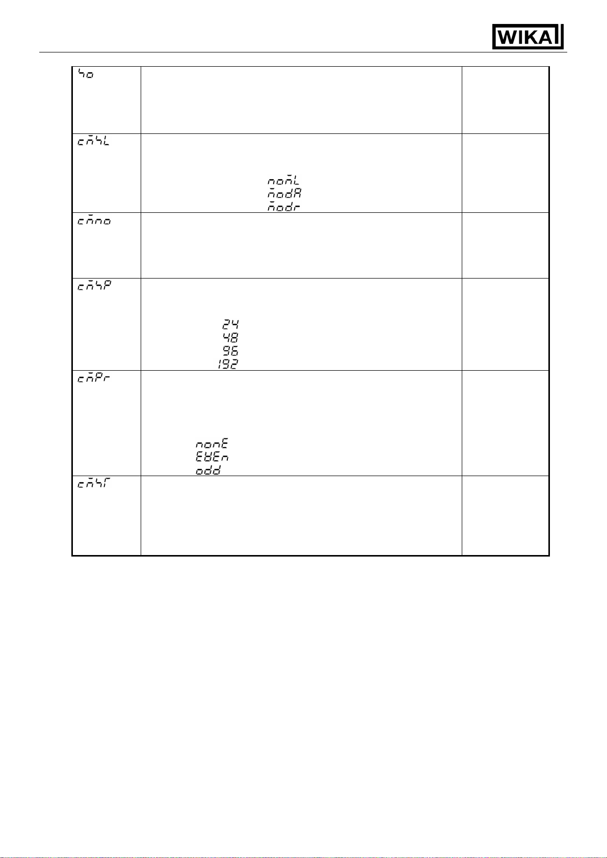
Sensor correction setting
• Sets the sensor correction value of the sensor.
• Thermocouple and RTD inputs : –100.0 … 100.0°C (°F)
DC voltage and current inputs : –1000 … 1000
(The placement of the decimal point follows the selection.)
Communication protocol selection
• Selects communication protocol.
• Available only when the option Digital interface [5] is added.
• WIKA protocol :
Modbus ASCII mode :
Modbus RTU mode :
Instrument number setting
• Sets an individual instrument number to each CS4R when
connecting plural CS4R in serial communication.
• Available only when the option Digital interface [5] is added.
• Setting range: 0 … 95
Data transfer rate selection
• Selects a data transfer rate in accordance with host computer
• Available only when the option Digital interface [5] is added.
• 2400bps :
4800bps :
9600bps :
19200bps :
Parity selection
• Selects the parity.
• Not available when the option Digital interface [5] is not added
or when WIKA protocol is selected in Communication protocol
selection
• None :
Even :
Odd :
Stop bit selection
• Selects the stop bit.
• Not available when the option Digital interface [5] is not added
or when WIKA protocol is selected in Communication protocol
selection
• Setting range: 1 or 2
0.0°C
WIKA protocol
0
9600bps
Even
1
V1.2 • 05/2006 - 13 -
Page 14

Operating Instructions Temperature Indicating Controller CS4R
5.5 Auxiliary function setting mode 2
Character Name, Description, Setting range Default value
Input type selection
• Selects a sensor type and temperature unit from thermocouple (10
types), RTD (2 types), DC current (2 types) and DC voltage (4
types).
• When changing input type from DC voltage input to the others,
detach the sensor connected to this unit before changing.
Input circuit will break down if input type is changed while the
sensor is connected.
K –200 ... 1370 °C:
–199.9 ... 400.0 °C:
J –200 ... 1000 °C:
R 0 ... 1760 °C:
S 0 ... 1760 °C:
B 0 ... 1820 °C:
E –200 ... 800 °C:
T –199.9 ... 400.0°C:
N –200 ... 1300 °C:
0 ... 1390 °C:
PLC (W/Re5-26) 0 ... 2315 °C:
Pt100 –199.9 ... 850.0 °C:
JPt100 –199.9 ... 500.0 °C:
Pt100 –200 ... 850 °C:
JPt100 –200 ... 500 °C:
4 ... 20mA DC –1999 ... 9999:
0 ... 20mA DC –1999 ... 9999:
0 ... 1V DC –1999 ... 9999:
0 ... 5V DC –1999 ... 9999:
1 ... 5V DC –1999 ... 9999:
0 ... 10V DC –1999 ... 9999:
Scaling high limit setting
• Sets the scaling high limit value.
The scaled high limit value is at the same time the maximal
adjustable set value.
• Scaling low limit setting value to Input range high limit value
(For DC voltage and current inputs, the placement of the decimal
point follows the selection.)
Scaling low limit setting
• Sets the scaling low limit value.
The scaled low limit value is at the same time the minimal
adjustable set value.
• Input range low limit value to scaling high limit setting value
(For DC voltage and current inputs, the placement of the decimal
point follows the selection.)
Decimal point place selection
• Selects the decimal point place.
However, not available if thermocouple or RTD input is selected
in the input type selection.
• No decimal point :
1 digit after decimal point :
2 digits after decimal point :
3 digits after decimal point :
PV filter time constant setting
• Sets the PV filter time constant.
If the setting value is too large, it affects control result due to the
response delay.
• Setting range: 0.0 … 10.0 seconds
K
(–200 … 1370°C)
K 320 ... 2500 °F:
–199.9 ... 750.0 °F:
J –320 ... 1800 °F:
R 0 ... 3200 °F:
S 0 ... 3200 °F:
B 0 ... 3300 °F:
E –320 ... 1500 °F:
T –199.9 ... 750.0 °F:
N –320 ... 2300 °F:
0 ... 2500 °F:
PL-
C (W/Re5-26) 0 ... 4200 °F:
Pt100 –199.9 ... 999.9 °F:
JPt100 –199.9 ... 900.0 °F:
Pt100 –300 ... 1500 °F:
JPt100 –300 ... 900 °F:
note:
With the input configuration 4 ... 20 mA or
0 ... 20 mA a 50Ω shunt resistor (sold
optionally) must be necessarily connected
between the terminals 5 and 6.
1370°C
–200°C
No decimal
point
0.0 seconds
V1.2 • 05/2006 - 14 -
Page 15
Operating Instructions Temperature Indicating Controller CS4R
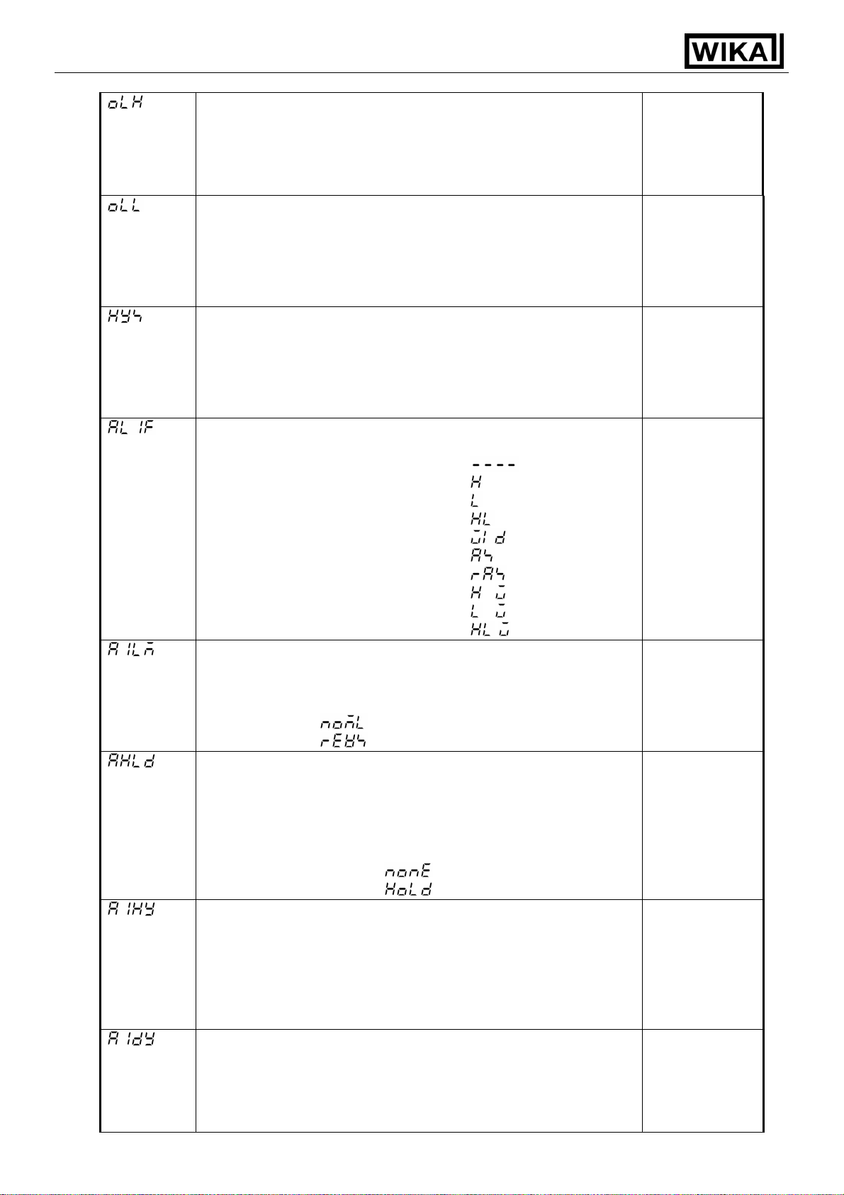
OUT high limit setting
• Sets the OUT high limit value.
• Not available for ON/OFF action.
• Setting range: OUT low limit value to 105%
Setting greater than 100% is effective to DC
current output type.
OUT low limit setting
• Sets the OUT low limit value.
• Not available for ON/OFF action.
• Setting range: –5% to OUT high limit value
Setting less than 0% is effective to DC current
output type.
OUT ON/OFF action hysteresis setting
• Sets the ON/OFF action hysteresis for the OUT.
• Available only for ON/OFF action (P=0).
• Thermocouple and RTD inputs : 0.1 … 100.0°C (°F)
DC voltage and current inputs : 1 … 1000
(The placement of the decimal point follows the selection)
Alarm action selection
• Selects an alarm action type.
No alarm action :
High limit Alarm :
Low limit alarm :
High/Low limits Alarm :
High/Low limit range Alarm :
Process high Alarm :
Process low Alarm :
High limit alarm with standby :
Low limit alarm with standby :
High/Low limits alarm with standby :
Alarm action Energized/Deenergized
• Selects the alarm action Energized/Deenergized.
• Not available when “No alarm action” is selected in Alarm action
selection.
• Energized :
Deenergized :
Alarm HOLD function selection
• Selects whether alarm HOLD function is [Used] or not.
If alarm HOLD function is set to [Used], once the alarm
functions, alarm output remains until the power is turned off.
• Not available when “No alarm action” is selected in Alarm
action selection.
• Alarm HOLD [Not used] :
Alarm HOLD [Used] :
Alarm hysteresis setting
• Sets the alarm hysteresis.
• Not available when “No alarm action” is selected in Alarm action
selection.
• Thermocouple and RTD inputs : 0.1 … 100.0°C (°F)
DC voltage and current inputs : 1 … 1000
(The placement of the decimal point follows the selection.)
Alarm action delayed timer setting
• Sets the alarm action delayed time. The alarm is activated
when the setting time has passed after the input enters alarm
output range.
• Not available when “No alarm action” is selected in Alarm action
selection.
100%
0%
1.0°C
No alarm action
Energized
Alarm HOLD
[Not used]
1.0°C
0 seconds
V1.2 • 05/2006 - 15 -
Page 16

Operating Instructions Temperature Indicating Controller CS4R
• Setting range: 0 … 9999 seconds
Direct/Reverse selection
• Selects reverse (heating) or direct (cooling) control action.
• Reverse (Heating) action :
Reverse
(Heating) action
Direct (Cooling) action :
AT bias setting
20°C
• Set the PID auto-tuning bias value.
• Not available when DC voltage or current input is selected
during input type selection, or when action is not PID, either.
Setting range: 0 ... 50°C (0 ... 100°F) or
•
0.0 ... 50.0
SVTC bias setting
°C (0.0 ... 100.0°F)
0
• Control desired value adds SVTC bias value to the value
received by the SVTC command.
• Available only when the option Digital interface [5] is added.
Controller/ Converter function selection
• Selects controller or converter function.
Controller
function
• Available only when the control output is analogue current signal
(4...20 mA).
• Controller function :
Converter function :
Output status selection when input burnout
Output OFF
• Selects whether the OUT output is turned OFF or not when DC
input is overscale or underscale.
• Available only for control output analogue current signal
(4 ... 20 mA) with DC inputs.
• Output OFF :
Output ON :
Sensor correction function
This corrects the input value from the sensor.
When a sensor cannot be set at a location where control is desired, the sensor measuring temperature
may deviate from the temperature in the controlled location. When controlling with multiple controllers,
the accuracy of the sensors or dispersion of load capacity has influence on the control.
Therefore, sometimes the measured temperature (input value) does not concur with the same setting
value. In such case the control can be set at the desired temperature by correcting the input value of
the sensors.
Loop break alarm
The alarm will be activated when the process variable (PV) does not rise as much value as the span or
greater within the time it takes to assess the Loop break alarm after the manipulated variable has
reached 100% or the output high limit value. The alarm will also be activated when the process variable
(PV) does not fall as much value as the span or greater within the time it takes to assess the Loop
break alarm after the manipulated variable has reached 0% or the output low limit value.
When the control action is Direct (Cooling), the alarm acts conversely.
V1.2 • 05/2006 - 16 -
Page 17

Operating Instructions Temperature Indicating Controller CS4R
Energized/Deenergized function
[If alarm action Energized is selected]
When the alarm output indicator is lit, the alarm output (between terminal 8 and 9) is conducted (ON).
When the alarm output indicator is unlit, the alarm output is not conducted (OFF).
[If alarm action Deenergized is selected]
When the alarm output indicator is lit, the alarm output (between terminal 8 and 9) is not conducted
(OFF).
When the alarm output indicator is unlit, the alarm output is conducted (ON).
High limit alarm (Energized setting) High limit alarm (Deenergized setting)
A1 hysteresis
A1 hysteresis
ON
ON
OFF
+ A1 set point
OFF
+ A1 set point
(Fig. 5.5-1) (Fig. 5.5-2)
5.6 Control output manipulated variable indication
Press the MODE key for approx. 3 seconds during PV/SV display mode.
Keep pressing the MODE key until the output manipulated variable shows up, though the main setting
mode appears during the process.
The control output manipulated variable is indicated on the SV display and the 1st
decimal point from the
right blinks in a 0.5 second cycle on the SV display.
Pressing the MODE key again, it reverts to the PV/SV display mode.
V1.2 • 05/2006 - 17 -
Page 18

Operating Instructions Temperature Indicating Controller CS4R
6. Converter function
Caution
• When using this controller as a converter, take 1 second into consideration since input/output
response time is approx. 1 second.
• When switching from converter function to controller function, the control parameter and values
set by converter function are held even if the function is switched to controller function.
So, correct the control parameter and values which has been set by converter function to the
values necessary for the controller function after switching to the controller function.
The converter function of this instrument converts each input value (thermocouple, RTD, DC voltage and
DC current inputs) to “4 ... 20mA DC” using the control parameter of the controller, and outputs it.
When this instrument is used as a converter, follow steps (1) to (7) described below.
After steps (1) to (7) are finished, this instrument can be used as a converter.
(1) Wire this controller (Power supply, Input and Output).
(2) Turn the power of this controller ON.
(3) Bring up “Auxiliary function setting mode 2” by pressing the
(4) Select the sensor type from “Input type selection (
(5) Set the high limit of the value that is going to be converted during “Scaling high limit setting ( )”.
(6) Set the low limit of the value that is going to be converted during “Scaling low limit setting ( )”.
(7) Select converter (
) from “Controller/Converter function selection ( )”.
and MODE key (for approx. 3s).
)”.
• To activate the alarm action by Converter function, set the alarm action to Process alarm action.
If converter function is selected from “Controller/Converter function selection” in Auxiliary function setting
mode 2, the parameters below are automatically set. (Table 6-1)
However, this is applied only to the output analogue current signal (4...20 mA).
(Table 6-1)
Setting item Setting value
SV Scaling low limit
Proportional band 100.0%
Integral time 0 seconds
Derivative time 0 seconds
Manual reset setting 0.0
Alarm setting 0
Loop break alarm action time 0 seconds
Loop break alarm action span 0
Direct/Reverse action selection Direct action
V1.2 • 05/2006 - 18 -
Page 19

Operating Instructions Temperature Indicating Controller CS4R
7. Running
When mounting and wiring to the control panel (DIN rail) are finished, start the operation following the next
procedure.
(1) Turn the power supply to the CS4R series ON.
For approx. 3s after power on, character of the sensor type and temperature unit are indicated on the PV
display, and the input range high limit value is indicated on the SV display. See (Table 5-1).
(If any other value is set at the scaling high limit value setting, SV display indicates it.)
During this time, all outputs and LED indicators are in OFF status.
After that PV display indicates actual temperature and SV display indicates the main setting value.
(2) Input the setting value.
Input each setting value referring to “5. Setup”.
(3) Turn the load circuit power ON.
Starts control action so as to keep temperature of the controlled object at the main setting value.
8. Action explanations
8.1 OUT action
Control output
relay
Control output
logic level
DC 0/12 V
Control output
analogue
current signal
(4...20 mA)
(OUT) Green
Control
action
Indicator
ON
OFF
3
4
Cycle action is performed according to deviation
+
3
12V DC
4
Cycle action is performed according to deviation
+
3
20mA DC 20 to 4mA DC
4
Changes continuously according to deviation
Lit Unlit
part : Acts ON or OFF.
Heating
(Reverse)
Proportional band
3
4
3
++
12/0V DC
4
3
4
action
SV setting
3
4
3
0V DC
4
3
4mA DC
4
Unlit
Cooling (Direct) action
Proportional band
ON
OFF
SV setting
3
4
Cycle action is performed according to deviation
++
3
0V DC 12V DC
4
Cycle action is performed according to deviation
+++
3
4mA DC
4
Changes continuously according to deviation
3
4
3
0/12V DC
4
3
4 to 20mA DC
4
3
4
+
3
4
++
3
20mA DC
4
Lit
V1.2 • 05/2006 - 19 -
Page 20

Operating Instructions Temperature Indicating Controller CS4R
8.2 OUT ON/OFF action
Heating (reverse) action
Hysteresis
Cooling (direct) action
Hysteresis
Control
action
ON
ON
Control output
relay
OFF
SV setting
3
4
3
4
SV setting
3
4
OFF
3
4
+
Control output
logic level
DC 0/12 V
Control output
analogue
current signal
(4...20 mA)
3
12V DC
4
+
3
20mA DC
4
+
3
4
+
3
4mA DC
4
0V DC
+
3
4
+
3
4mA DC
4
0V DC
+
3
12V DC
4
+
3
20mA DC
4
Indication
(OUT) Green
Lit Unlit
Unlit Lit
part: Acts ON or OFF.
V1.2 • 05/2006 - 20 -
Page 21

Operating Instructions Temperature Indicating Controller CS4R
8.3 Event (Alarm) action
Alarm
action
ON
OFF
Alarm
output
+ side
side
High limit alarm
A1 set point
High/Low limit range alarm
SV
setting
Low limit alarm
A1 hysteresis
+ A1 set point
A1 hysteresis A1 hysteresis A1 hysteresis
A1 hysteresis
ON
OFF
A1 set point SV
+ side
side
setting
Process high alarm
Alarm
action
Alarm
output
Alarm
action
Alarm
output
ON
OFF
ON
OFF
+ side
side
A1 set point A1 set point
High limit alarm with standby High/Low limit alarm with standbyLow limit alarm with standby
A1 set point
setting
setting
A1 set point
SV
A1 hysteresis A1 hysteresis A1 hysteresis
SV
+ A1 set point
ON
OFF
+ side
side
ON
OFF
A1 set point
A1 set point
SV
setting
Event (EVT) output indicator lights up when output terminals between
8 and 9 is ON, and goes out when between them is OFF.
: Event (EVT) output terminals between 8 and 9 is ON.
: Event (EVT) output terminals between 8 and 9 is ON or OFF.
: Event (EVT) output terminals between 8 and 9 is OFF.
: Standby functions in this section.
+ A1 set point
ON
OFF
A1 set pointA1 set point
ON
OFF
ON
OFF
A1 set point SV
High/Low limits alarm
A1 hysteresis
SV
setting
Process low alarm
setting
A1 set point
A1 set point
8.4 Event (Heater burnout alarm) action
ON
Heater burnout
alarm action
OFF
Heater burnout alarm set point
LargeSmall
Load current
Indication
(EVT) Red
UnlitLit
: Event (EVT) output terminals between 8 and 9 is ON
: Event (EVT) output terminals between 8 and 9 is OFF
Event (EVT) output indicator lights up when output terminals between 8 and 9 is ON
and goes out when between them is OFF.
V1.2 • 05/2006 - 21 -
Page 22

Operating Instructions Temperature Indicating Controller CS4R
9. PID auto-tuning of the CS4R
In order to decide each P, I, D and ARW value automatically, this system gives a fluctuation to the controlled
object to get an optimal value. 1 of 3 types of fluctuation below is automatically selected.
[When the difference between the setting value and processing temperature is large as the
temperature rises]
When AT bias is set to 20°C (°F), fluctuation is applied at the temperature 20°C (°F) lower than the setting
value.
Temperature 20°C (°F) lower than the setting value
Setting
value
Temperature
(4)
AT starting point
(1)
Time
(2) (3)
(1) Calculating PID constant
(2) PID constant calculated
(3) Controlled by the PID
constant set by auto-tuning.
(4) AT bias value
[When control is stable]
Fluctuation is applied at the setting value.
Setting
value
(1) Calculating PID constant
(2) PID constant calculated
(3) Controlled by the PID
Temperature
constant set by auto-tuning
AT starting point
Time
(1) (2) (3)
[When the difference between the setting value and processing temperature is large as the
temperature falls]
When AT bias is set to 20°C (°F), fluctuation is applied at the temperature 20°C (°F) higher than the setting
value.
Temperature 20°C (°F) higher than the setting value
(1) Calculating PID constant
Temperature
(2) PID constant calculated
(3) Controlled by the PID
Setting
value
(4)
constant set by auto-tuning.
(4) AT bias value
AT starting point
Time
(1) (2)
(3)
V1.2 • 05/2006 - 22 -
Page 23

Operating Instructions Temperature Indicating Controller CS4R
10. Specifications
10.1 Standard specification
Model name : DIN rail mounting type indicating controller
Mounting method : DIN rail mounting method
Setting method : Input system using membrane sheet key
Display
PV display : Red LED 4 digits, character size 7.5 x 4.1 mm (H x W)
SV display : Green LED 4 digits, character size 7.5 x 4.1 mm (H x W)
Input
Thermocouple : K, J, R, S, B, E, T, N, PL-
External resistance: 100Ω or less
However, for thermocouple B, external resistance, 40Ω or less
RTD : Pt100, JPt100, 3-wire system
Allowable input lead wire resistance: 10Ω or less per wire
DC current : 0 … 20mA DC, 4 … 20mA DC, input impedance 50Ω
[Connect 50Ω shunt resistor (sold optionally) between input terminals 5 and 6]
Allowable input current: 50mA or less
DC voltage :
0 … 1V DC 0 … 5V / 1 … 5V / 0 … 10V DC
Input impedance 1MΩ or greater 100kΩ or greater
Allowable input voltage 5V or less 15V or less
Allowable signal source
resistance
Accuracy (Setting and Indication)
Thermocouple : Within ±0.2% of input span ±1 digit, or within ±2°C (4°F) whichever is greater
R, S inputs, 0 … 200°C (0 … 400°F): Within ±6°C (12°F)
B input, 0 … 300°C (0 … 600°F): Accuracy is not guaranteed.
K, J, E, T, N inputs, less than 0°C (32°F): Within ±0.4% of input span ±1 digit
RTD : Within ±0.1% of input span ±1 digit, or within ±1°C (2°F) whichever is greater
DC voltage : Within ±0.2% of input span ±1 digit
DC current : Within ±0.2% of input span ±1 digit
Input sampling period : 0.25 seconds
Control action
• PID action (with auto-tuning function)
• PI action : When derivative time is set to 0
• PD action (with manual reset function) : When integral time is set to 0
• P action (with manual reset function) : When derivative and integral times are set to 0
• ON/OFF action : When proportional band is set to 0
, C (W/Re5-26)
2kΩ or less 100Ω or less
Setting ranges of the control parameters :
OUT proportional band : 0.0 to 110.0% (ON/OFF action when set to 0.0)
Integral time : 0 to 1000 seconds (Off when set to 0)
Derivative time : 0 to 300 seconds (Off when set to 0)
OUT proportional cycle : 1 to 120 seconds
ARW : 0 to 100%
Manual reset : ± Proportional band converted value
Output limit : 0 to 100% (DC current output type: –5 to 105%)
(Not available for ON/OFF action)
Hysteresis : Thermocouple and RTD inputs: 0.1 to 100.0°C (°F)
DC voltage and current inputs: 1 to 1000
(The placement of the decimal point follows the selection)
V1.2 • 05/2006 - 23 -
Page 24

Operating Instructions Temperature Indicating Controller CS4R
Control output (OUT)
• Relay contact : Control capacity 3A 250V AC (Resistive load)
1A 250V AC (Inductive load COS ø =0.4)
Electrical life, 100,000 times
• Logic level DC 0/12 V (non-contact voltage for SSR drive):
+ 2
12
V DC max. 40mA (Short circuit protected)
- 0
• Analogue current signal : 4 … 20mA DC
Load resistance : max. 550Ω
Output accuracy : Within ±0.3% of output span
Resolution : 12000
EVT output
• Alarm output [Common output with Loop break alarm and Heater burnout alarm (option)]
The alarm action point is set by ± deviation to the main setting (excluding Process alarm) and when
input exceeds the range, alarm (EVT) is turned ON or OFF (High/Low limit range alarm).
When Deenergized is selected during the Energized/Deenergized selection, alarm (EVT) is activated
conversely.
Setting accuracy : The same as indication accuracy
Action : ON/OFF action
Hysteresis : Thermocouple and RTD inputs : 0.1 … 100.0°C (°F)
DC voltage and current inputs : 1 … 1000 (The placement of the
decimal point follows the selection)
Output : Open collector, Control capacity 24V DC 0.1A (Max.)
Alarm output action : One alarm action is selectable from below by front key operation:
High limit, Low limit, High/Low limits, High/Low limit range, Process high,
Process low, High limit with standby, Low limit with standby,
High/Low limits with standby and No alarm action.
Energized/Deenergized : Alarm (EVT) output Energized/Deenergized can be selected.
Energized Deenergized
Red (EVT) LED Lights Lights
EVT output ON OFF
Alarm HOLD function selection : Once the alarm is activated, alarm output is held until
the power is turned off.
• Loop break alarm output (Common output with Alarm and Heater burnout alarm [Option])
Detects heater burnout, sensor burnout and actuator trouble.
Setting range:
time setting : 0 … 200 minutes
span setting : 0 … 150°C (°F) or 0.0 … 150.0°C (°F)
DC voltage and current inputs: 0 … 1500
(the placement of the decimal point follows the selection)
Output : Open collector
control capacity 24V DC 0.1A (max.)
Converter function : See “6. Converter function”
V1.2 • 05/2006 - 24 -
Page 25

Operating Instructions Temperature Indicating Controller CS4R
Isolation • Dielectric strength: Circuit isolation configuration
CT input
5
Input
CPU
76
98
EVT
Communication
1 2
Isolated
OUTPower supply
4
3
* When OUT is logic level DC 0/12 V (non-contact voltage) or
analogue current signal, between OUT and communication
is non-isolated.
Isolation resistance : 10MΩ or greater at 500V DC
Dielectric strength : 1.5kV AC for 1 minute between input terminal and power terminal
1.5kV AC for 1 minute between output terminal and power terminal
Power supply : 100 … 240V AC 50/60Hz or
24V AC/DC 50/60Hz
Allowable voltage fluctuation range
100 … 240V AC : 85 … 264V AC
24V AC/DC : 20 … 28V AC
Power consumption : Approx. 6VA
Ambient temperature : 0 … 50°C
Ambient humidity : 35 … 85%RH (no condensation)
Mass : Approx.120g
External dimension : 22.5 x 75 x 100mm (W x H x D)
Material : Flame resistant resin (Case)
Color : Light gray (Case)
V1.2 • 05/2006 - 25 -
Page 26

Operating Instructions Temperature Indicating Controller CS4R
Attached functions
[Sensor correction]
[Setting value Lock]
[Indication and control range monitoring]
• If the input value exceeds the Indication range high limit value, the PV display blinks “
if the input value exceeds the Indication range low limit value, the PV display blinks “ ”.
• If the input value exceeds the Control range, OUT is turned OFF (for DC current output type, OUT
low limit value).
However, for manual control, it outputs the preset manipulated variable.
Indication and Control ranges with Thermocouple and RTD inputs
Input Input range Indication range Control range
K, T
K
J
R, S
B
E
N
PL-
C(W/Re5-26)
Pt100
–199.9 ... 400.0°C –199.9 ... 450.0°C –205.0 ... 450.0°C
–199.9 ... 750.0°F –199.9 ... 850.0°F –209.0 ... 850.0°F
–200 ... 1370°C –250 ... 1420°C –250 ... 1420°C
–320 ... 2500°F –370 ... 2550°F –370 ... 2550°F
–200 ... 1000°C –250 ... 1050°C –250 ... 1050°C
–320 ... 1800°F –370 ... 1850°F –370 ... 1850°F
0 ... 1760°C –50 ... 1810°C –50 ... 1810°C
0 ... 3200°F –50 ... 3250°F –50 ... 3250°F
0 ... 1820°C –50 ... 1870°C –50 ... 1870°C
0 ... 3300°F –50 ... 3350°F –50 ... 3350°F
–200 ... 800°C –250 ... 850°C –250 ... 850°C
–320 ... 1500°F –370 ... 1550°F –370 ... 1550°F
–200 ... 1300°C –250 ... 1350°C –250 ... 1350°C
–320 ... 2300°F –370 ... 2350°F –370 ... 2350°F
0 ... 1390°C –50 ... 1440°C –50 ... 1440°C
0 ... 2500°F –50 ... 2550°F –50 ... 2550°F
0 ... 2315°C –50 ... 2365°C –50 ... 2365°C
0 ... 4200°F –50 ... 4250°F –50 ... 4250°F
–199.9 ... 850.0°C
–199.9 ... 900.0°C –210.0 ... 900.0°C
–200 ... 850°C –210 ... 900°C –210 ... 900°C
–199.9 ... 999.9°F –199.9 ... 999.9°F –211.0 ... 1099.9°F
–300 ... 1500°F –318 ... 1600°F –318 ... 1600°F
–199.9 ... 500.0°C –199.9 ... 550.0°C –206.0 ... 550.0°C
JPt100
–200 ... 500°C –206 ... 550°C –206 ... 550°C
–199.9 ... 900.0°F –199.9 ... 999.9°F –211.0 ... 999.9°F
–300 ... 900°F –312 ... 1000°F –312 ... 1000°F
”, and
Indication range with DC current and voltage inputs
[Scaling low limit value – Scaling span x 1%] … [Scaling high limit value + Scaling span x 10%]
However, if the input value exceeds the range –1999 … 9999, the PV display blinks “
or “ ”.
Control range with DC current and voltage inputs
[Scaling low limit value – Scaling span x 1%] … [Scaling high limit value + Scaling span x 10%]
[Input burnout monitoring]
Input Indication on the PV display at input burnout
Thermocouple blinks [ ]
RTD blinks [ ]
4 ... 20 mA DC blinks [ ]
0 ... 20 mA DC scaled low limit setting
0 ... 1 V DC blinks [ ]
0 ... 5 V DC scaled low limit setting
1 ... 5 V DC blinks [ ]
0 ... 10 V DC scaled low limit setting
V1.2 • 05/2006 - 26 -
”
Page 27

Operating Instructions Temperature Indicating Controller CS4R
[Self diagnosis]
The CPU is monitored by a watchdog timer, and when any abnormal status is found on the CPU, the
controller is switched to warm-up status with all outputs turned off.
[Automatic cold junction temperature compensation] (Only thermocouple input)
This detects the temperature at the connection terminal between the thermocouple and the
instrument and always keeps it on the same status as when the reference junction is located at
0°C (32°F).
[Power failure countermeasure]
The setting data is backed up in non-volatile IC memory.
10.2 Optional specifications
Heater burnout alarm (Option code: [W1x])
Watches the heater current with CT (Current transformer) and detects the burnout.
When this option is added, this option shares common output with Alarm and Loop break alarm.
This option cannot be applied to DC current output type.
Rating : 5A [W10], 10A [W11)], 20A [W12], 50A [W15] (Must be specified)
Setting range : 5A [W10], 0.0 … 5.0A (Off when set to 0.0)
10A [W11], 0.0 … 10.0A (Off when set to 0.0)
20A [W12], 0.0 … 20.0A (Off when set to 0.0)
50A [W15], 0.0 … 50.0A (Off when set to 0.0)
Setting accuracy : ±5% of the rated value
Action : ON/OFF action
Output : Open collector
Control capacity 24V DC 0.1A (max.)
Digital interface (Option code: [5])
The following operations are performed from external computer.
(1) Reading and setting of the main setting value, PID and other various setting values
(2) Reading of the input value and action status
(3) Function change
Communication interface : Based on EIA RS-485
Communication method : Half-duplex communication start-stop synchronous
Data transfer rate : 2400/4800/9600/19200bps (Selectable by key operation)
Parity : Even/Odd/No (Selectable by key operation)
Stop bit : 1 or 2 (Selectable by key operation)
Communication protocol : WIKA/Modbus RTU/Modbus ASCII (Selectable by key operation)
Number of connectable units : A maximum of 31 units per host computer
Communication error detection : Dual detection by the parity and checksum
Digital external setting : SV of programmable controller (with option SVTC) can be transmitted
digitally to the CS4R (with option serial Interface [5]) by combining the
programmable controller with the CS4R.
[Setting value Lock of the CS4R must be set to Lock 3.]
When data from the programmable controller is greater than SV high
limit or smaller than SV low limit, CS4R ignores the value and controls
with the former value.
Control desired value is the value that is added SVTC bias value to
the received value by SVTC command.
V1.2 • 05/2006 - 27 -
Page 28

Operating Instructions Temperature Indicating Controller CS4R
11. Troubleshooting
If any malfunctions occur, refer to the following items after checking the power supply to the controller.
11.1 Indication
Problem Presumed cause and solution
[ ] is blinking on
the PV display.
[ ] is blinking on
the PV display.
The value set during
the Scaling low limit
setting remains on the
PV display.
• The sensor of thermocouple, RTD and DC voltage (0 … 1 V DC) input may
be burnt out.
Replace each sensor.
How to check sensor burnout
[Thermocouple]
If the input terminal of the instrument is shorted, and if nearby room
temperature is indicated, the instrument should be normal and the sensor
may be burnt out.
[RTD]
If approx. 100Ω resistance is connected to the input terminals between
A-B of the instrument and between B-B is shorted, and if nearby 0 °C
(32 °F) is indicated, the instrument should be normal and the sensor may
be burnt out.
[DC voltage (0 … 1 V DC)]
If the input terminal of the instrument is shorted, and if scaling low limit
value is indicated, the instrument should be normal and the signal wire
may be burnt out.
• Is the input terminal of thermocouple, RTD or DC voltage (0 … 1 V DC)
securely mounted to the instrument terminal?
Connect the sensor terminal to the instrument terminal securely.
• The input signal wire for DC voltage (1 … 5 V DC) or DC current
(4 … 20 mA DC) may be burnt out.
Replace each input signal wire.
How to check input signal wire burnout
[DC voltage (1 … 5 V DC)]
If the input to the input terminal of this controller is 1 V DC and if scaling
low limit value is indicated, the controller should be normal and the signal
wire may be burnt out.
[DC current (4 … 20 mA DC)]
If the input to the input terminal of this controller is 4 mA DC and if scaling
low limit value is indicated, the controller should be normal and the signal
wire may be burnt out.
• Is the input signal wire for DC voltage (1 … 5 V DC) and DC current
(4 … 20 mA DC) securely connected to the input terminal of this controller?
Connect the input signal wire to the controller terminal securely.
• Polarity of thermocouple or compensating lead wire is reversed?
Do codes (A, B, B) of RTD agree with the controller terminal?
Wire them properly.
• Is the input signal wire for DC voltage (0 … 5 V DC, 0 … 10 V DC)or DC
current (0 … 20 mA DC) burnt out?
Replace each input signal wire.
How to check input signal wire burnout
[DC voltage (0 … 5 V DC, 0 … 10 V DC)]
If the input to the input terminal of this controller is 1 V DC and if the
corresponding value is indicated, the controller should be normal and the
signal wire may be burnt out.
[DC current (0 … 20 mA DC)]
If the input to the input terminal of this controller is 1 mA DC and if the
corresponding value is indicated, the controller should be normal and the
signal wire may be burnt out.
• Is the input signal wire for DC voltage (0 … 5 V DC, 0 …10 V DC) and
DC current (0 … 20 mA DC) securely connected to the input terminal of this
controller?
Connect the signal wire to the controller terminal securely.
V1.2 • 05/2006 - 28 -
Page 29

Operating Instructions Temperature Indicating Controller CS4R
The indication of PV
display is abnormal or
unstable.
• Designation of the sensor input or temperature unit (°C or °F) is improper.
Set the sensor input and the temperature unit properly.
• Sensor correcting value is unsuitable.
Set the value suitably.
• Sensor specification is improper.
Set the sensor specification properly.
• AC may be leaking into the sensor circuit.
Change the sensor for the ungrounded type.
• There may be an equipment producing an inductive fault or noise near the
controller.
Keep the equipment producing an inductive fault or noise away from the
controller.
[ ] is indicated on
the PV display.
• The internal memory is defective.
Please contact our main office or dealers.
11.2 Key operation
Problem Presumed cause and solution
Settings (SV, P, I, D,
proportional cycle, alarm,
etc.) are impossible.
The value does not change
by the
, keys.
The setting indication does
not change within the rated
input range even if the
• Setting value lock (Lock 1 or Lock 2) is designated.
Release the lock designation.
• During PID auto-tuning
Cancel the auto-tuning if necessary.
• SV high limit or low limit may be set at the point the value does not
change.
,
Set it again while in Auxiliary function setting mode 1.
keys are pressed, and
settings are impossible.
11.3 Control
Problem Presumed cause and solution
Process variable
(temperature) does not rise.
• The sensor is out of order.
Replace the sensors.
• Sensor is not securely mounted to the instrument input terminal, or
control output terminal is not securely mounted to the actuator input
terminal.
Mount the sensor or control output terminal securely.
• Is wiring of sensor terminal or control output terminal correct?
Wire it correctly.
The control output remains
ON status.
• OUT low limit value is set to 100% or greater in Auxiliary function
setting mode 2.
Set the value appropriately.
The control output remains
OFF status.
• OUT high limit value is set to 0% or less in Auxiliary function setting
mode 2.
Set the value appropriately.
• If you have any inquiries, please consult our agency or the shop where you purchased the unit.
V1.2 • 05/2006 - 29 -
Page 30

Operating Instructions Temperature Indicating Controller CS4R
12. Character table (to copy and complete for your documentation)
[Main setting mode]
Character Setting item Default value Data
[Sub setting mode]
Character Setting item Default value Data
Set value 0 °C
AT Auto-Tuning cancellation
OUT proportional band setting 2.5 %
Integral time 200 s
Derivate time setting 50 s
ARW setting 50 %
OUT proportional cycle setting 30 s or 3 s
Manual reset setting 0.0
Alarm setting 0 °C
Heater burnout alarm setting 0.0 A
Loop break alarm action time setting 0 min
Loop break alarm action span setting 0 °C
[Auxiliary function setting mode 1]
Character Setting item Default value Data
Setting value lock selection Unlock
Sensor correction setting 0.0 °C
Communication protocol selection WIKA protocol
Instrument number setting 0
Data transfer rate selection 9600 bps
Parity selection Even
Stop bit selection 1
[Auxiliary function setting mode 2]
Character Setting item Default value Data
Input type selection K: –200 ... +1370 °C
Scaling high limit setting 1370
Scaling low limit setting –200
Decimal point place selection no decimal point
PV filter time constant setting 0.0 s
OUT high limit setting 100 %
OUT low limit setting 0 %
OUT ON/OFF action hysteresis 1.0 °C
Alarm action selection no alarm action
Alarm action Energized/Deenergized energized
Alarm HOLD function selection not used
Alarm hysteresis setting 1.0 °C
Alarm action delayed timer setting 0 s
Direct/Reverse action selection Reverse (heating) action
AT bias setting 20 °C
SVTC bias setting 0
Controller/converter function selection controller function
Output status selection when input burnout output OFF
V1.2 • 05/2006 - 30 -
Page 31

Operating Instructions Temperature Indicating Controller CS4R
V1.2 • 05/2006 - 31 -
 Loading...