

Page 1
Operating Instructions
Process pressure transmitter CPT-2x
Process pressure transmitter CPT-2x
Slave for electronic dierential pressure
With SIL qualication
Ceramic sensor
Page 2

2
Contents
WIKA Operating Instructions - Process pressure transmitter CPT-2x
Contents
1 About this document ............................................................................................................... 4
1.1 Function ........................................................................................................................... 4
1.2 Target group ..................................................................................................................... 4
1.3 Symbols used................................................................................................................... 4
2 For your safety ......................................................................................................................... 5
2.1 Authorised personnel ....................................................................................................... 5
2.2 Appropriate use ................................................................................................................ 5
2.3 Warning about incorrect use ............................................................................................. 5
2.4 General safety instructions ............................................................................................... 5
2.5 EU conformity ................................................................................................................... 6
2.6 SIL qualication according to IEC 61508 .......................................................................... 6
2.7 Permissible process pressure .......................................................................................... 6
2.8 Installation and operation in the USA and Canada ........................................................... 6
3 Product description ................................................................................................................. 7
3.1 Conguration .................................................................................................................... 7
3.2 Principle of operation........................................................................................................ 8
3.3 Supplementary cleaning procedures .............................................................................. 13
3.4 Packaging, transport and storage ................................................................................... 14
4 Mounting ................................................................................................................................. 15
4.1 General instructions ....................................................................................................... 15
4.2 Ventilation and pressure compensation .......................................................................... 16
4.3 Combination Master - Slave ........................................................................................... 18
4.4 Level measurement ........................................................................................................ 20
4.5 Dierential pressure measurement ................................................................................ 21
4.6 Interface measurement .................................................................................................. 21
4.7 Density measurement .................................................................................................... 22
4.8 Density-compensated level measurement ..................................................................... 23
4.9 External housing ............................................................................................................ 25
5 Connecting to power supply ................................................................................................. 26
5.1 Preparing the connection ............................................................................................... 26
5.2 Connecting ..................................................................................................................... 26
5.3 Single chamber housing ................................................................................................. 28
5.4 External housing with version IP 68 (25 bar)................................................................... 28
5.5 Connection example ...................................................................................................... 30
6 Functional safety (SIL) .......................................................................................................... 31
6.1 Objective ........................................................................................................................ 31
6.2 SIL qualication .............................................................................................................. 31
6.3 Application area ............................................................................................................. 31
6.4 Safety concept of the parameterization .......................................................................... 32
7 Set up with the display and adjustment module ................................................................ 34
7.1 Parameter adjustment .................................................................................................... 34
8 Diagnosis, asset management and service ........................................................................ 47
8.1 Maintenance .................................................................................................................. 47
8.2 Cleaning - hygienic connection with compression nut .................................................... 47
8.3 Rectify faults ................................................................................................................... 48
Page 3

3
Contents
WIKA Operating Instructions - Process pressure transmitter CPT-2x
8.4 Exchange process module on version IP 68 (25 bar) ..................................................... 48
8.5 Instrument repair ............................................................................................................ 49
9 Dismount................................................................................................................................. 51
9.1 Dismounting steps.......................................................................................................... 51
9.2 Disposal ......................................................................................................................... 51
10 Supplement ............................................................................................................................ 52
10.1 Technical data ................................................................................................................ 52
10.2 Calculation of the total deviation ..................................................................................... 62
10.3 Practical example ........................................................................................................... 63
10.4 Dimensions .................................................................................................................... 66
10.5 Trademark ...................................................................................................................... 74
Safety instructions for Ex areas
Take note of the Ex specic safety instructions for Ex applications.
These instructions are attached as documents to each instrument
with Ex approval and are part of the operating instructions manual.
Editing status: 2017-11-23
Page 4
4
1 About this document
WIKA Operating Instructions - Process pressure transmitter CPT-2x
1 About this document
1.1 Function
This operating instructions manual provides all the information you
need for mounting, connection and setup as well as important instructions for maintenance, fault rectication, the exchange of parts and
the safety of the user. Please read this information before putting the
instrument into operation and keep this manual accessible in the im-
mediate vicinity of the device.
1.2 Target group
This operating instructions manual is directed to trained personnel.
The contents of this manual must be made available to the qualied
personnel and implemented.
1.3 Symbols used
Information, tip, note
This symbol indicates helpful additional information.
Caution: If this warning is ignored, faults or malfunctions can result.
Warning: If this warning is ignored, injury to persons and/or serious
damage to the instrument can result.
Danger: If this warning is ignored, serious injury to persons and/or
destruction of the instrument can result.
Ex applications
This symbol indicates special instructions for Ex applications.
•
List
The dot set in front indicates a list with no implied sequence.
→
Action
This arrow indicates a single action.
1 Sequence of actions
Numbers set in front indicate successive steps in a procedure.
Battery disposal
This symbol indicates special information about the disposal of batteries and accumulators.
Page 5

5
2 For your safety
WIKA Operating Instructions - Process pressure transmitter CPT-2x
2 For your safety
2.1 Authorised personnel
All operations described in this operating instructions manual must
be carried out only by trained specialist personnel authorised by the
plant operator.
During work on and with the device the required personal protective
equipment must always be worn.
2.2 Appropriate use
CPT-2x is a slave sensor for electronic dierential pressure measure-
ment.
You can nd detailed information about the area of application in
chapter "Product description".
Operational reliability is ensured only if the instrument is properly
used according to the specications in the operating instructions
manual as well as possible supplementary instructions.
2.3 Warning about incorrect use
Inappropriate or incorrect use of this product can give rise to application-specic hazards, e.g. vessel overll through incorrect mounting
or adjustment. Damage to property and persons or environmental
contamination can result. Also, the protective characteristics of the
instrument can be impaired.
2.4 General safety instructions
This is a state-of-the-art instrument complying with all prevailing
regulations and directives. The instrument must only be operated in a
technically awless and reliable condition. The operator is responsible for the trouble-free operation of the instrument. When measuring
aggressive or corrosive media that can cause a dangerous situation
if the instrument malfunctions, the operator has to implement suitable
measures to make sure the instrument is functioning properly.
During the entire duration of use, the user is obliged to determine the
compliance of the necessary occupational safety measures with the
current valid rules and regulations and also take note of new regulations.
The safety instructions in this operating instructions manual, the national installation standards as well as the valid safety regulations and
accident prevention rules must be observed by the user.
For safety and warranty reasons, any invasive work on the device
beyond that described in the operating instructions manual may be
carried out only by personnel authorised by the manufacturer. Arbitrary conversions or modications are explicitly forbidden. For safety
reasons, only the accessory specied by the manufacturer must be
used.
Page 6

6
2 For your safety
WIKA Operating Instructions - Process pressure transmitter CPT-2x
To avoid any danger, the safety approval markings and safety tips on
the device must also be observed and their meaning looked up in this
operating instructions manual.
2.5 EU conformity
The device fulls the legal requirements of the applicable EU directives. By axing the CE marking, we conrm the conformity of the
instrument with these directives.
2.6 SILqualicationaccordingtoIEC61508
The Safety Integrity Level (SIL) of an electronic system is used to assess the reliability of integrated safety functions.
For detailed specication of the safety requirements, multiple SIL
levels are specied according to safety standard IEC 61508. You can
nd detailed information in chapter "Functional safety (SIL)" of the
operating instructions.
The instrument meets the specications of IEC 61508: 2010 (Edition 2). It is qualied for single-channel operation up to SIL2. The
instrument can be used homogeneously redundant up to SIL3 in
multi-channel architecture with HFT 1.
2.7 Permissible process pressure
For safety reasons, the instrument must only be operated within the
permissible process conditions. You can nd detailed information on
the process conditions in chapter "Technical data" as well as on the
type label.
The permissible process pressure range is specied on the type label
with "Process pressure", see chapter "Conguration". This applies
even if a measuring cell with a measuring range (order-related) higher
than the permissible pressure range of the process tting is installed.
A temperature derating, e.g. with anges, can limit the permissible
process pressure range.
2.8 Installation and operation in the USA and
Canada
This information is only valid for USA and Canada. Hence the following text is only available in the English language.
Installations in the US shall comply with the relevant requirements of
the National Electrical Code (ANSI/NFPA 70).
Installations in Canada shall comply with the relevant requirements of
the Canadian Electrical Code
Page 7

7
3 Product description
WIKA Operating Instructions - Process pressure transmitter CPT-2x
3 Product description
3.1 Conguration
The type label contains the most important data for identication and
use of the instrument:
4
1
5
10
12
11
13
14
3
2
6
7
8
9
Fig. 1: Layout of the type label (example)
1 Instrument type
2 Field for approvals
3 Power supply and signal output, electronics
4 Protection rating
5 Measuring range
6 Permissible process conditions
7 Material wetted parts
8 Product code
9 Order number
10 Serial number of the instrument
11 Symbol of the device protection class
12 ID numbers, instrument documentation
13 Reminder to observe the instrument documentation
14 SIL identication
This operating instructions manual applies to the following instrument
versions:
•
Hardware from 1.0.0
•
Software version from 1.0.0
Note:
You can nd the hardware and software version of the instrument as
follows:
•
On the type plate of the electronics module
•
In the adjustment menu under "Info"
The scope of delivery encompasses:
•
Instrument CPT-2x - Slave sensor
•
Ready-made connection cable, unassembled cable gland
•
Documentation
– Quick setup guide CPT-2x
– Safety Manual (SIL)
Type label
Scope of this operating
instructions manual
Scope of delivery
Page 8
8
3 Product description
WIKA Operating Instructions - Process pressure transmitter CPT-2x
– Documentation instrument parameters (default values)
– Documentation order-relating instrument parameters (deviation
from default values)
– Test certicate for pressure transmitters
– Instructions for optional instrument features
– Ex-specic "Safety instructions" (with Ex versions)
– If necessary, further certicates
Information:
Optional instrument features are also described in this operating
instructions manual. The respective scope of delivery results from the
order specication.
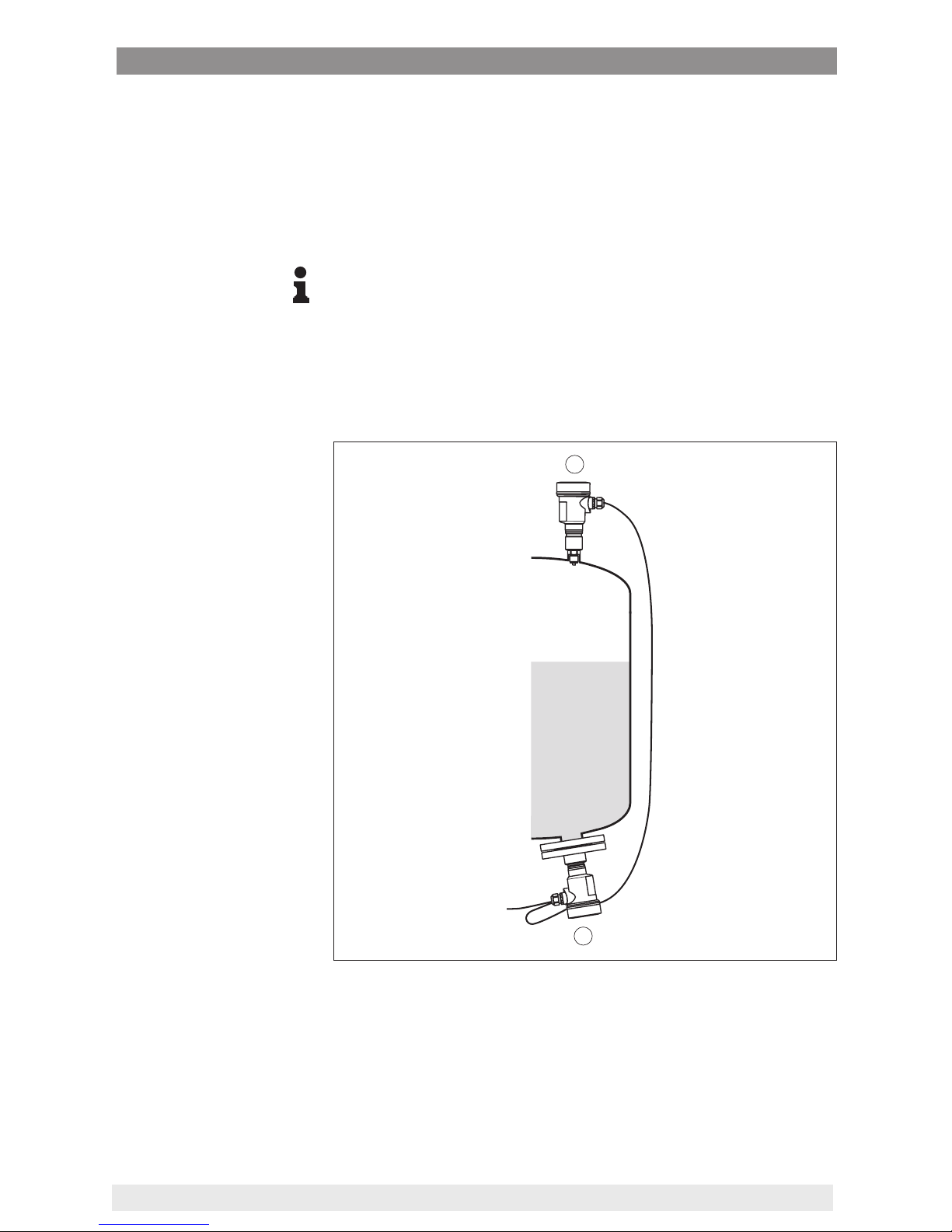
3.2 Principle of operation
The CPT-2x slave sensor is combined with a sensor from the instrument series for electronic dierential pressure measurement.
1
2
Fig. 2: Example, electronic dierential pressure for level measurement in pressurized vessel
1 CPT-2x
2 CPT-2x, slave sensor
The sensors are connected via a screened four-wire cable. The
measured value from the slave sensor is read in and factored into the
calculations. Power supply and parameter adjustment are carried out
through the master sensor.
Electronicdierential
pressure
Page 9
9
3 Product description
WIKA Operating Instructions - Process pressure transmitter CPT-2x
Information:
The version "Relative pressure climate-compensated" is not suitable.
You can nd further information in chapter "Combination Master -
Slave " of this operating instructions.
To reach the Safety Integrity Level (SIL) for the electronic dierential
pressure, both instruments must be SIL-qualied.
The electronic dierential pressure measurement is suitable for the
measurement of the following process variables:
•
Level
•
Flow
•
Dierential pressure
•
Density
•
Interface
•
Level, density-compensated
CPT-2x is suitable for applications in virtually all industries. It is used
for the measurement of the following pressure types.
•
Gauge pressure
•
Absolute pressure
•
Vacuum
Measured products are gases, vapours and liquids.
Depending on the process tting and measurement setup, measured
products can be also viscous or contain abrasive substances.
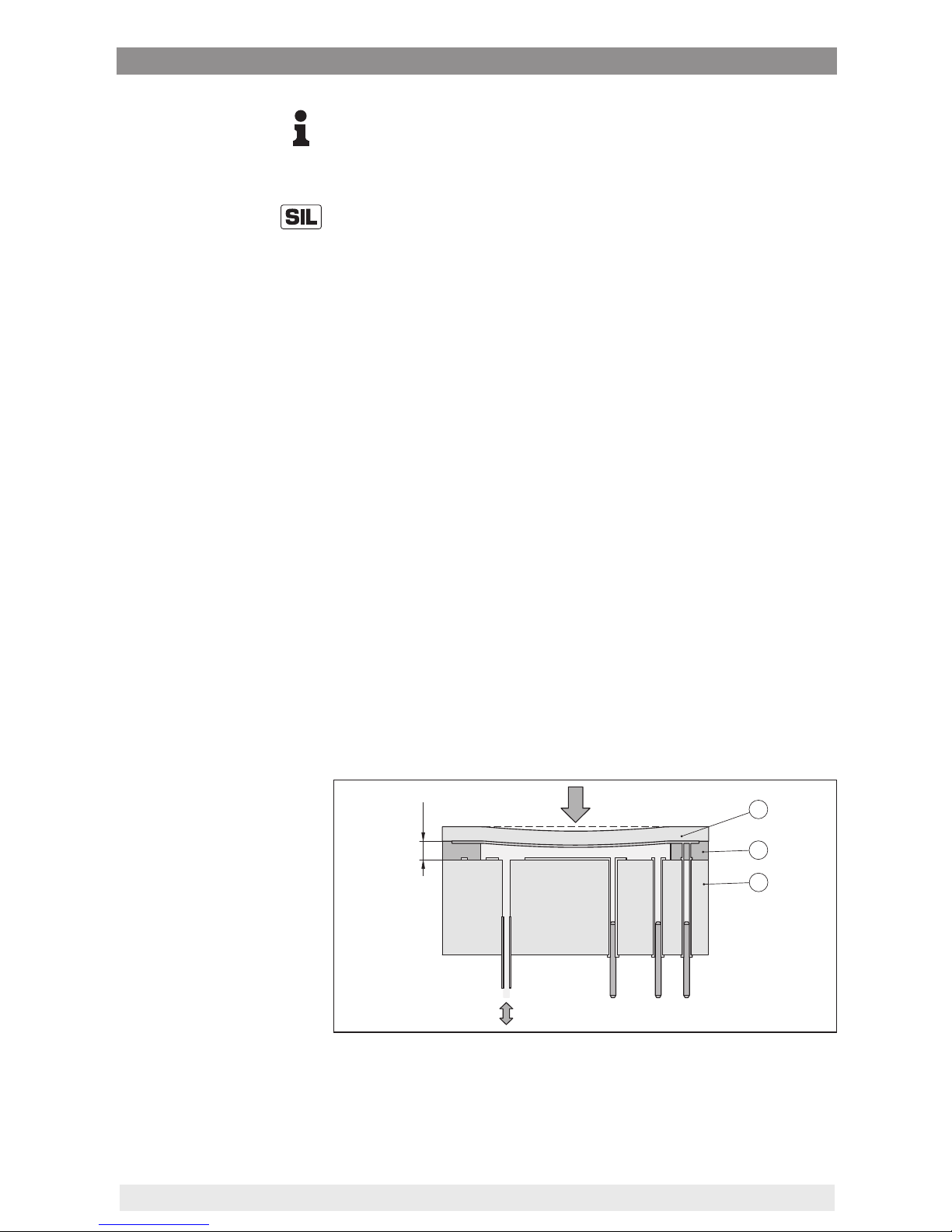
Sensor element is the measuring cell with robust ceramic diaphragm.
The process pressure deects the ceramic diaphragm and causes a
capacitance change in the measuring cell. This capacitance change
is converted into an electrical signal and outputted as measured value
via the output signal.
16 µm
1
2
3
Fig. 3: Conguration of the ceramic measuring cell
1 Process diaphragm
2 Glass joint
3 Base element
The measuring cell is available in two sizes:
Measured variables
Application area
Measured products
Measuring system pressure
Page 10

10
3 Product description
WIKA Operating Instructions - Process pressure transmitter CPT-2x
•
ø 28 mm with large process and ange connections as well as with
measuring ranges 25 mbar and 100 bar
•
ø 17.5 mm with small process ttings
A temperature sensor in the ceramic diaphragm of the ø 28 mm or on
the ceramic base of the ø 17.5 mm measuring cell detects the actual
process temperature. The temperature value is outputted via the
master sensor.
Extreme process temperature jumps are also immediately detected
by the ø 28 mm measuring cell. The values are compared with that of
an additional temperature measurement on the ceramic base body.
Within only a few measuring cycles the intelligent sensor electronics
compensates unavoidable measurement deviations due to temperature shocks. Such shocks cause (depending on the set damping) only
slight, brief changes to the output signal.
The measuring cell design depends on the selected pressure type.
Relative pressure: the measuring cell is open to the atmosphere.
The ambient pressure is detected in the measuring cell and compensated. It thus has no inuence on the measured value.
Absolute pressure: the measuring cell is evacuated and encapsulated. The ambient pressure is not compensated and does hence
inuence the measured value.
The following presentations show examples for the installation of the
ceramic measuring cell into the process tting and the dierent seal
concepts.
The recessed installation is particularly suitable for applications with
gases, vapours and clear liquids. The measuring cell seal is positioned laterally as well as in addition in front.
Measuring system temper
atur
e
Pressure types
Seal concepts
Recessed installation
Page 11
11
3 Product description
WIKA Operating Instructions - Process pressure transmitter CPT-2x
1
2
5
6
3
4
Fig. 4: Recessed installation of the measuring cell (example: manometer connection G½)
1 Measuring cell
2 Seal for the measuring cell
3 Additional, front seal for measuring cell
4 Diaphragm
5 Process tting
6 Seal for the process tting
The front-ush installation is particularly suitable for applications with
viscous and abrasive media and in case of buildup. The measuring
cell seal is positioned laterally.
2
3
4
1
5
Fig. 5: Front-ush installation of the measuring cell (example: thread G1½)
1 Seal for the process tting
2 Measuring cell
3 Seal for the measuring cell
4 Process tting
5 Diaphragm
The completely front-ush mounting is particularly suitable for ap-
plications in the paper industry. The diaphragm is in the pulp ow, is
hence cleaned and protected against buildup.
Front-ushmountingwith
single seal
Completelyfront-ush
mounting with single seal
Page 12
12
3 Product description
WIKA Operating Instructions - Process pressure transmitter CPT-2x
1
2
3
4
5
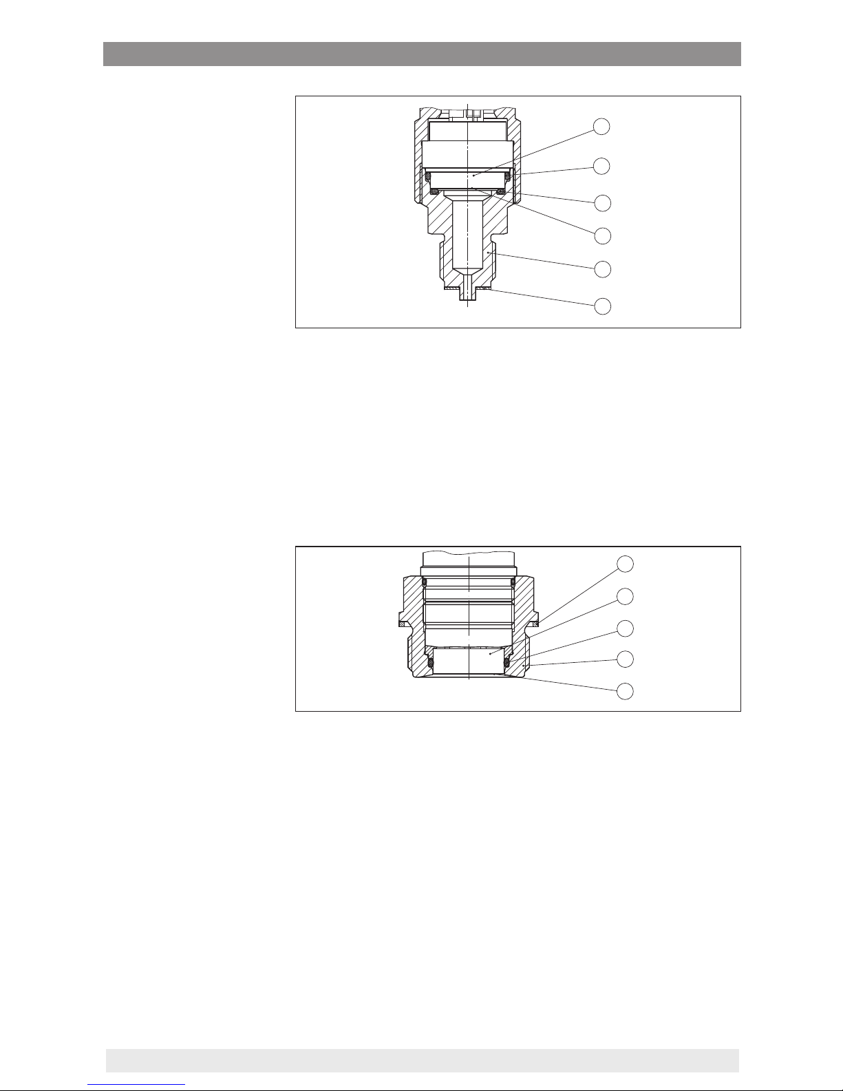
Fig. 6: Front-ush installation of the measuring cell (example: M30 x 1.5)
1 Measuring cell
2 Seal for the measuring cell
3 Seal for the process tting
4 Process tting
5 Diaphragm
The front-ush installation is particularly suitable for applications with
viscous media. The additional, front sealing protects the glass joint
of the measuring cell against chemical attack and the measuring cell
electronics against diusion of aggressive gases from the process.
1
2
3
4
5
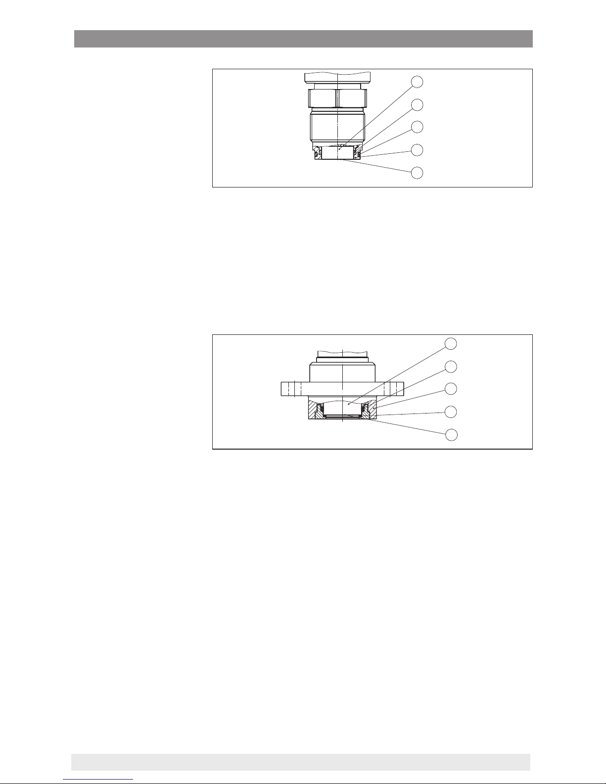
Fig. 7: Front-ush installation of the measuring cell with double seal (example:
ange connection with extension)
1 Measuring cell
2 Seal for the measuring cell
3 Process tting
4 Additional, front seal for measuring cell
5 Diaphragm
The front-ush, hygienic installation of the measuring cell is particularly suitable for food applications. The sealings are installed gap-free.
The form seal of the measuring cell protects also the glass joint.
Front-ushmountingwith
double seal
Installation in hygienic
tting
Page 13
13
3 Product description
WIKA Operating Instructions - Process pressure transmitter CPT-2x
1
2
3
4
5
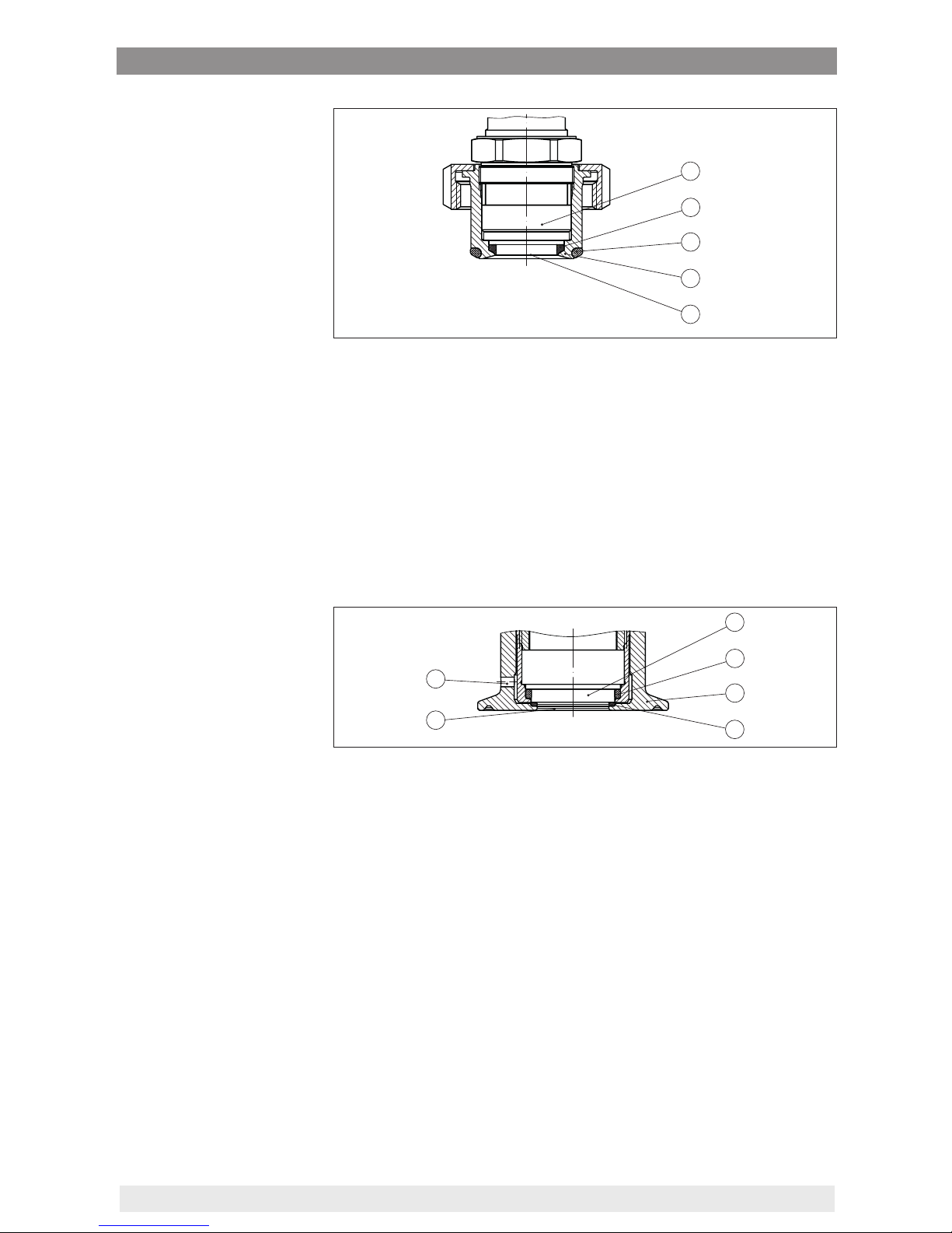
Fig. 8: Hygienic installation of the measuring cell (example: hygienic tting with
compression nut)
1 Measuring cell
2 Form seal for the measuring cell
3 Gap-free seal for process tting
4 Process tting
5 Diaphragm
The front-ush, hygienic installation of the measuring cell acc. to 3A
is particularly suitable for food applications. The sealings are installed
gap-free. The additional front sealing for the measuring cell protects
also the glass joint. A hole in the process tting is used for leakage
detection.
1
6
2
3
4
5
Fig. 9: Hygienic installation of the measuring cell acc. to 3-A (example: Clamp
connection)
1 Measuring cell
2 Seal for the measuring cell
3 Process tting
4 Additional, front seal for measuring cell
5 Diaphragm
5 Hole for leakage detection
3.3 Supplementary cleaning procedures
The CPT-2x is also available in the version "Oil, grease and silicone-
free". These instruments have passed through a special cleaning
procedure to remove oil, grease and paint-wetting impairment substances (PWIS).
The cleaning is carried out on all wetted parts as well as on surfaces
accessible from outside. To keep the purity level, the instruments are
immediately packed in plastic foil after the cleaning process. The
purity level remains as long as the instrument is kept in the closed
original packaging.
Installation in hygienic
ttingacc.to3-A
Page 14

14
3 Product description
WIKA Operating Instructions - Process pressure transmitter CPT-2x
Caution:
The CPT-2x in this version may not be used in oxygen applications.
For this purpose, instruments are available in the special version "Oil
and grease-free for oxygen applications".
3.4 Packaging, transport and storage
Your instrument was protected by packaging during transport. Its
capacity to handle normal loads during transport is assured by a test
based on ISO 4180.
The packaging of standard instruments consists of environmentfriendly, recyclable cardboard. For special versions, PE foam or PE
foil is also used. Dispose of the packaging material via specialised
recycling companies.
Transport must be carried out in due consideration of the notes on the
transport packaging. Nonobservance of these instructions can cause
damage to the device.
The delivery must be checked for completeness and possible transit
damage immediately at receipt. Ascertained transit damage or concealed defects must be appropriately dealt with.
Up to the time of installation, the packages must be left closed and
stored according to the orientation and storage markings on the
outside.
Unless otherwise indicated, the packages must be stored only under
the following conditions:
•
Not in the open
•
Dry and dust free
•
Not exposed to corrosive media
•
Protected against solar radiation
•
Avoiding mechanical shock and vibration
•
Storage and transport temperature see chapter "Supplement Technical data - Ambient conditions"
•
Relative humidity 20 … 85 %
With an instrument weight of more than 18 kg (39.68 lbs) suitable and
approved equipment must be used for lifting and carrying.
Packaging
Transport
Transport inspection
Storage
Storage and transport
temperature
Lifting and carrying
Page 15

15
4 Mounting
WIKA Operating Instructions - Process pressure transmitter CPT-2x
4 Mounting
4.1 General instructions
Make sure before mounting that all parts of the instrument exposed to
the process are suitable for the existing process conditions.
These are mainly:
•
Active measuring component
•
Process tting
•
Process seal
Process conditions in particular are:
•
Process pressure
•
Process temperature
•
Chemical properties of the medium
•
Abrasion and mechanical inuences
You can nd detailed information on the process conditions in chapter
"Technical data" as well as on the type label.
The instrument is suitable for standard and extended ambient condi-
tions acc. to DIN/EN/IEC/ANSI/ISA/UL/CSA 61010-1.
Protect your instrument against moisture ingress through the following
measures:
•
Use a suitable connection cable (see chapter "Connecting to
power supply")
•
Tighten the cable gland
•
When mounting horizontally, turn the housing so that the cable
gland points downward
•
Loop the connection cable downward in front of the cable gland
This applies mainly to outdoor installations, in areas where high
humidity is expected (e.g. through cleaning processes) and on cooled
or heated vessels.
To maintain the housing protection, make sure that the housing lid is
closed during operation and locked, if necessary.
Make sure that the degree of contamination specied in chapter
"Technical data" meets the existing ambient conditions.
On instruments with threaded process tting, the hexagon must be
tightened with a suitable wrench. For the proper wrench size see
chapter "Dimensions".
Warning:
The housing must not be used to screw the instrument in! Applying
tightening force can damage internal parts of the housing.
If there is strong vibration at the mounting location, the instrument
version with external housing should be used. See chapter "External
housing".
Suitability for the process
conditions
Suitability f
or the ambient
conditions
Pr
otection against mois-
ture
Screwing in
Vibrations
Page 16
16
4 Mounting
WIKA Operating Instructions - Process pressure transmitter CPT-2x
Higher process temperatures often mean also higher ambient
temperatures. Make sure that the upper temperature limits stated in
chapter "Technical data" for the environment of the electronics hous-
ing and connection cable are not exceeded.
1
2
Fig. 10: Temperature ranges
1 Process temperature
2 Ambient temperature
4.2 Ventilation and pressure compensation
Ventilation and pressure compensation are carried out with CPT-2x
via a lter element. It is air permeable and moisture-blocking.
Caution:
The lter element causes a time-delayed pressure compensation.
When quickly opening/closing the housing cover, the measured value
can change for approx. 5 s by up to 15 mbar.
For eective ventilation, the lter element must always be free of
buildup.
Caution:
Do not use a high-pressure cleaner. The lter element could be damaged, which would allow moisture into the housing.
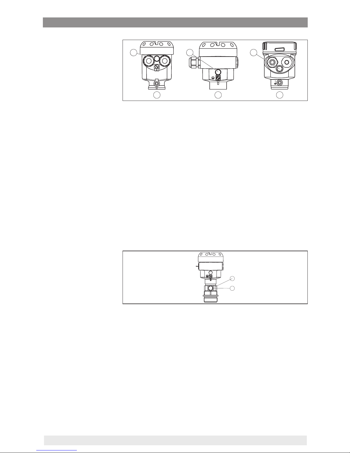
The following paragraphs describe how the lter element is arranged
in the dierent instrument versions.
The lter element is mounted into the electronics housing. It has the
following functions:
•
Ventilation of the electronics housing
•
Atmospheric pressure compensation (with relative pressure measuring ranges)
→
Turn the housing so that the lter element points downward after
the instrument is installed. This provides better protection against
buildup.
Temperature limits
Filter elements
Instruments in non-Ex
and Ex-ia version
Page 17
17
4 Mounting
WIKA Operating Instructions - Process pressure transmitter CPT-2x
1 2 3
4 4 4
Fig. 11: Position of the lter element - non-Ex, Ex-ia version
1 Plastic, stainless steel housing (precision casting)
2 Aluminium housing
3 Stainless steel housing (electropolished)
4 Filter element
With the following instruments a blind plug is installed instead of the
lter element:
•
Instruments in protection IP 66/IP 68 (1 bar) - ventilation via capillaries in non-detachable cable
•
Instruments with absolute pressure
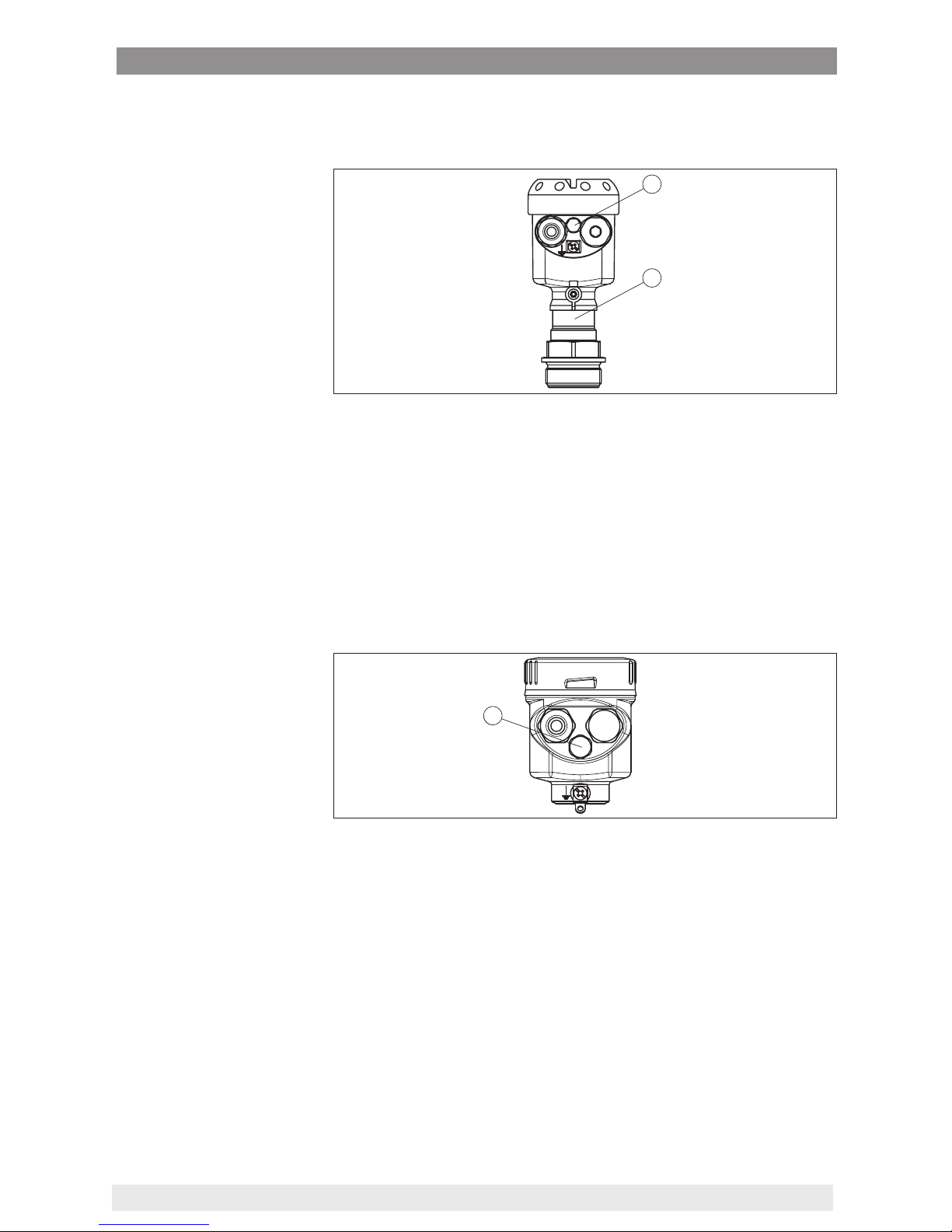
The lter element is integrated in the process assembly. It is located in
a rotatable metal ring and has the following function:
•
Atmospheric pressure compensation (with relative pressure measuring ranges)
→
Turn the metal ring in such a way that the lter element points
downward after installation of the instrument. This provides better
protection against buildup.
1
2
Fig. 12: Position of the lter element - Ex-d version
1 Rotatable metal ring
2 Filter element
Instruments with absolute pressure have a blind plug mounted
instead of the lter element.
The lter element is mounted into the electronics housing. It has the
following functions:
•
Ventilation of the electronics housing
→
Turn the housing so that the lter element points downward after
the instrument is installed. This provides better protection against
buildup.
Instruments in Ex-d version
Instruments with Second
Line of Def
ense
Page 18
18
4 Mounting
WIKA Operating Instructions - Process pressure transmitter CPT-2x
The process assembly of instruments with Second Line of Defense
(gastight leadthrough) is completely encapsulated. An absolute pressure measuring cell is used so that no ventilation is required.
1
2
Fig. 13: Position of the lter element - gastight leadthrough
1 Filter element
The lter element is mounted into the electronics housing. It has the
following functions:
•
Ventilation of the electronics housing
•
Atmospheric pressure compensation (with relative pressure measuring ranges)
→
Turn the housing so that the lter element points downward after
the instrument is installed. This provides better protection against
buildup.
1
Fig. 14: Position of the lter element - IP 69K version
1 Filter element
Instruments with absolute pressure have a blind plug mounted
instead of the lter element.
4.3 Combination Master - Slave
In principle, any sensor combination within the instrument series is
allowed. The following requirements must be fullled:
•
Conguration, Master sensor suitable for electronic dierential
pressure
•
Pressure type is identical for both sensors, i.e. relative pressure/
relative pressure or absolute pressure/absolute pressure
•
Master sensor measures the higher pressure
•
Measurement setup as shown in the following chapters
Instruments in IP 69K
version
Page 19

19
4 Mounting
WIKA Operating Instructions - Process pressure transmitter CPT-2x
The measuring range of each sensor is selected such that it ts the
measuring loop. For this, the max. recommended turn down must be
noted. See chapter "Technical data". It is absolutely necessary the the
measuring ranges of Master and Slave correspond.
Measurement result = Measured value of Master (total pressure) - measured value of Slave (static pressure)
Depending on the application, individual combinations can result, see
following examples:
Data
Application: Level measurement
Medium: Water
Vessel height: 12 m, hydrostatic pressure = 12 m x 1000 kg/m3 x
9.81 m/s2 = 117.7 kPa = 1.18 bar
Superimposed pressure: 1 bar
Total pressure: 1.18 bar + 1 bar = 2.18 bar
Instrument selection
Nominal measuring range Master: 2.5 bar
Nominal measuring range Slave: 1 bar
Turn Down: 2.5 bar/1.18 bar = 2.1 : 1
Data
Application: Level measurement
Medium: Water
Vessel height: 500 mm, hydrostatic pressure = 0.50 m x 1000 kg/m3 x
9.81 m/s2 = 4.9 kPa = 0.049 bar
Superimposed pressure: 350 mbar = 0.35 bar
Total pressure: 0.049 bar + 0.35 bar = 0.399 bar
Instrument selection
Nominal measuring range Master: 0.4 bar
Nominal measuring range Slave: 0.4 bar
Turn Down: 0.4 bar /0.049 bar = 8.2 : 1
Data
Application: Dierential pressure measurement
Medium: Gas
Static pressure: 0.8 bar
Dierential pressure on orice: 50 mbar = 0.050 bar
Total pressure: 0.8 bar + 0.05 bar = 0.85 bar
Instrument selection
Nominal measuring range Master: 1 bar
Nominal measuring range Slave: 1 bar
Turn Down: 1 bar/0.050 bar = 20 : 1
Example - large vessel
Example - small vessel
Example-oricein
pipeline
Page 20
20
4 Mounting
WIKA Operating Instructions - Process pressure transmitter CPT-2x
The measuring result (level, pressure dierence) as well as measured
value Slave (static or superimposed pressure) are outputted by the
sensor. Depending on the instrument version, output as 4 … 20 mA
signal or digitally via HART, Probus PA or Foundation Fieldbus.
To reach the Safety Integrity Level (SIL) for the electronic dierential
pressure, both instruments must be SIL-qualied.
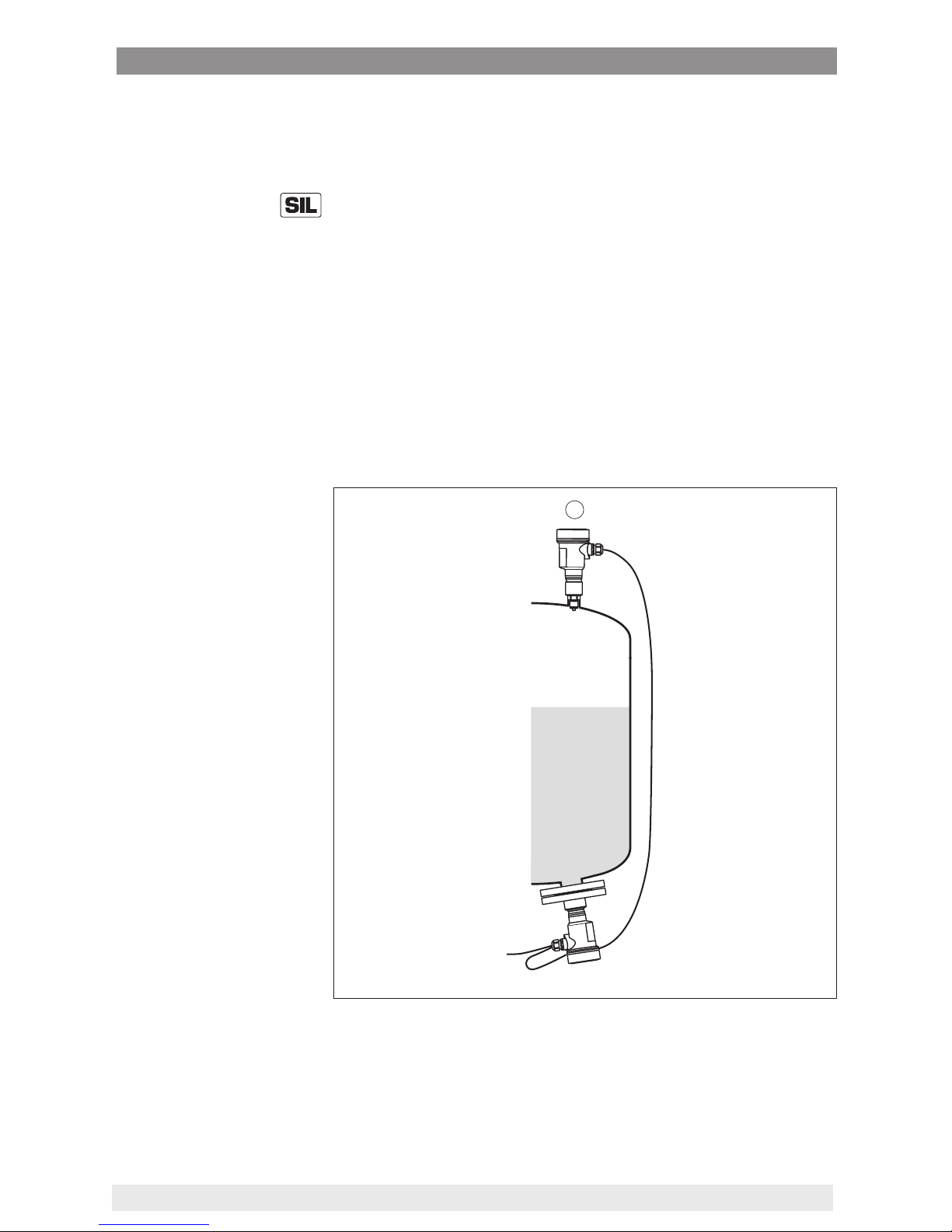
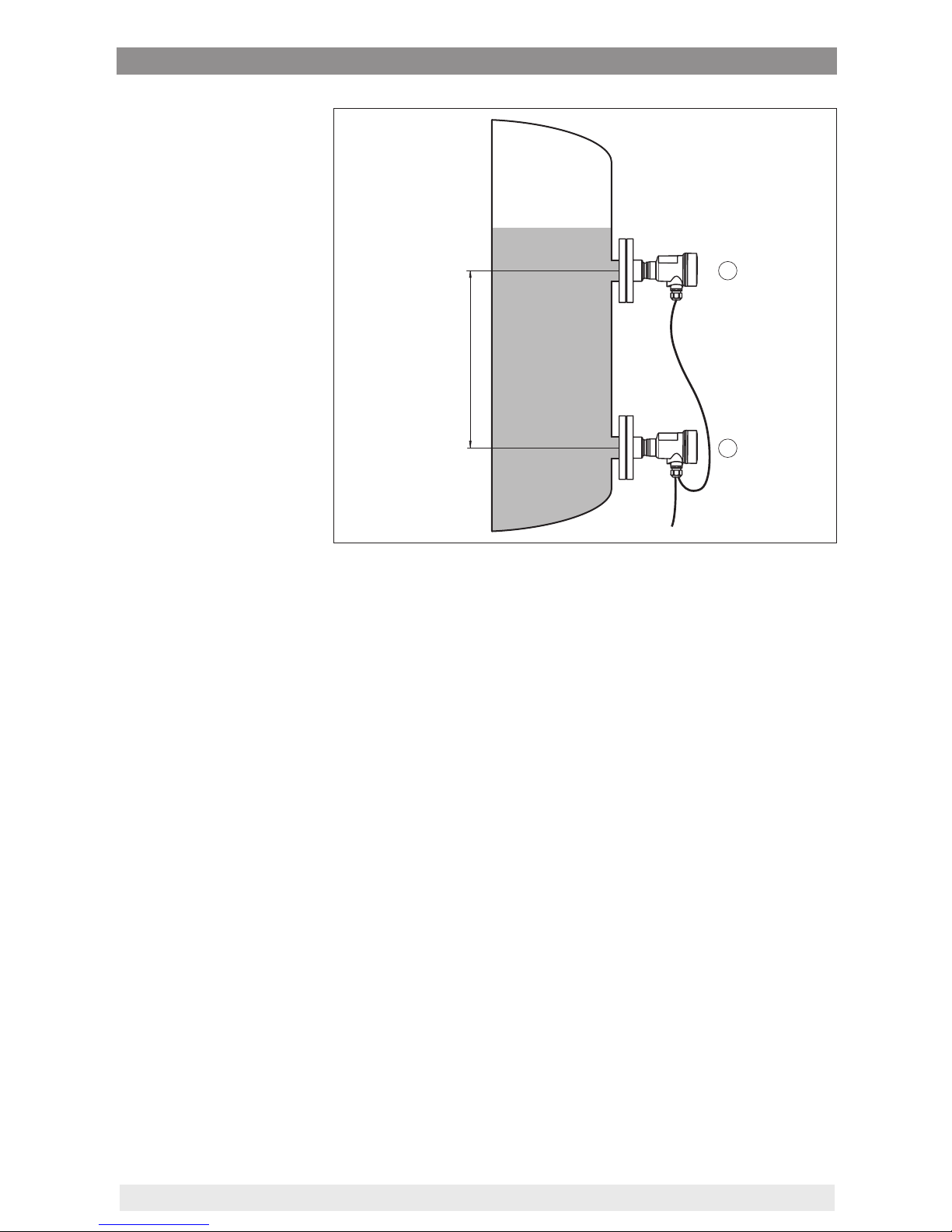
4.4 Level measurement
The master/slave combination is suitable for level measurement in a
pressurized vessel
Keep the following in mind when setting up the measuring system:
•
Mount the master sensor below the min. level
•
Do not mount the master sensor close to the lling stream or
emptying area
•
Mount the master sensor so that it is protected against pressure
shocks from the stirrer
•
Mount the slave sensor above the max. level
2
Fig. 15: Measurement setup, level measurement in pressurized vessel
1 CPT-2x
2 CPT-2x, slave sensor
Output measured values
Measurement setup
Page 21

21
4 Mounting
WIKA Operating Instructions - Process pressure transmitter CPT-2x
4.5 Dierentialpressuremeasurement
The master/slave combination is suitable for dierential pressure
measurement
Take note of the following instructions for the measurement setup, for
example in gases:
•
Mount the instruments above the measuring point
Possible condensation can then drain o into the process line.
1
2
Fig. 16: Measurement setup for dierential pressure measurement of gases in
pipelines
1 CPT-2x
2 CPT-2x, slave sensor
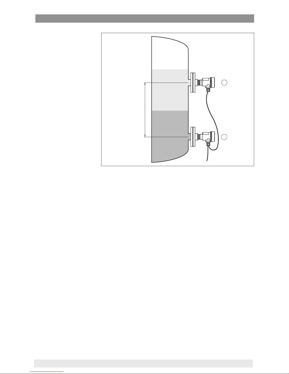
4.6 Interface measurement
The master/slave combination is suitable for interface measurement
Requirements for a functioning measurement are:
•
Vessel with changing level
•
Products with steady density
•
Interface always between the measurement points
•
Total level always above the upper measurement point
The mounting distance h of the two sensors should be at least 10 %,
better 20 %, of the nal value of the sensor measuring range. A bigger
distance increases the accuracy of the interface measurement.
Measurement setup
Measurement setup
Page 22
22
4 Mounting
WIKA Operating Instructions - Process pressure transmitter CPT-2x
h
1,0
0,8
1
2
Fig. 17: Measurement setup with interface measurement, h = distance between
the two measuring points
1 CPT-2x
2 CPT-2x, slave sensor
The interface measurement is possible in open as well as in closed
vessels.
4.7 Density measurement
The master/slave combination is suitable for density measurement.
Requirements for a functioning measurement are:
•
Vessel with changing level
•
Distance between the measurement points as large as possible
•
Level always above the upper measuring point
Measurement setup
Page 23
23
4 Mounting
WIKA Operating Instructions - Process pressure transmitter CPT-2x
h
1
2
Fig. 18: Measurement setup for density measurement, h = distance between the
two measuring points
1 CPT-2x
2 CPT-2x, slave sensor
The mounting distance h of the two sensors should be at least 10 %,
better 20 %, of the nal value of the sensor measuring range. A bigger
distance increases the accuracy of the density measurement.
Slight density changes cause only slight changes of the measured
dierential pressure. The measuring range must hence be selected
accordingly.
The density measurement is possible in open as well as in closed
vessels.
4.8 Density-compensated level measurement
The master/slave combination is suitable for density-compensated
level measurement
Keep the following in mind when setting up the measuring system:
•
Mount the master sensor below the min. level
•
Mount the slave sensor above the master sensor
•
Mount both sensors away from the lling stream and emptying and
protected against pressure shocks from the stirrer
Measurement setup
Page 24

24
4 Mounting
WIKA Operating Instructions - Process pressure transmitter CPT-2x
h
1
2
Fig. 19: Measurement setup for density-compensated level measurement, h =
distance between the two measuring points
1 CPT-2x
2 CPT-2x, slave sensor
The mounting distance h of the two sensors should be at least 10 %,
better 20 %, of the nal value of the sensor measuring range. A bigger
distance increases the accuracy of the density compensation.
The density-compensated level measurement starts with the stored
density 1 kg/dm3. As soon as both sensors are covered, this value will
be replaced by the calculated density. Density compensation means
that the level value in height units and the adjustment values do not
change in case of a uctuating density.
The density-compensated level measurement is only possible in
open, i.e. unpressurized vessels.
Page 25

25
4 Mounting
WIKA Operating Instructions - Process pressure transmitter CPT-2x
4.9 External housing
1
2
3
4
5
Fig. 20: Conguration, process module, external housing
1 Pipeline
2 Process module
3 Connection cable process assembly - External housing
4 External housing
5 Signal cable
1. Mark the holes according to the following drilling template
2. Fasten wall mounting plate with 4 screws
90 mm
(3.54")
R 3,5 mm
(0.14")
3mm
(0.12")
70 mm
(2.76")
8 mm
(0.32")
93 mm
(3.66")
110 mm
(4.33")
Fig. 21: Drilling template - wall mounting plate
Conguration
Mounting
Page 26

26
5 Connecting to power supply
WIKA Operating Instructions - Process pressure transmitter CPT-2x
5 Connecting to power supply
5.1 Preparing the connection
Always keep in mind the following safety instructions:
Warning:
Connect only in the complete absence of line voltage.
•
The electrical connection must only be carried out by trained
personnel authorised by the plant operator.
•
If overvoltage surges are expected, overvoltage arresters should
be installed.
The voltage supply and the signal transmission are carried out via the
four-wire, screened connection cable from the master sensor.
You can nd the data for this signal circuit in chapter "Technical data".
The screening of the cable between master and slave sensor must
be connected on both ends to ground potential. In the sensor, the
screening is connected directly to the internal ground terminal. The
ground terminal on the outside of the housing must be connected to
the ground potential (low impedance).
Metric threads
In the case of instrument housings with metric thread, the cable
glands are screwed in at the factory. They are sealed with plastic
plugs as transport protection.
You have to remove these plugs before electrical connection.
NPT thread
In the case of instrument housings with self-sealing NPT threads, it is
not possible to have the cable entries screwed in at the factory. The
free openings for the cable glands are therefore covered with red dust
protection caps as transport protection.
Prior to setup you have to replace these protective caps with approved cable glands or close the openings with suitable blind plugs.
On plastic housings, the NPT cable gland or the Conduit steel tube
must be screwed into the threaded insert without grease.
Max. torque for all housings, see chapter "Technical data".
5.2 Connecting
The connection to the Master sensor is carried out through springloaded terminals in the respective housing. For this, use the supplied,
confectioned cable. Solid cores as well as exible cores with cable
end sleeves are inserted directly into the terminal openings.
In case of exible cores without end sleeves, press the terminal from
above with a small screwdriver, the terminal opening is then free.
When the screwdriver is released, the terminal closes again.
Safety instructions
Voltage supply
Cable screening and
grounding
Cable glands
Connection technology
Page 27

27
5 Connecting to power supply
WIKA Operating Instructions - Process pressure transmitter CPT-2x
Information:
The terminal block is pluggable and can be removed from the
electronics. To do this, lift the terminal block with a small screwdriver
and pull it out. When reinserting the terminal block, you should hear it
snap in.
You can nd further information on the max. wire cross-section under
"Technical data - Electromechanical data".
Proceed as follows:
1. Unscrew the housing lid
2. Loosen compression nut of the cable gland and remove blind
plug
3. Remove approx. 10 cm (4 in) of the cable mantle, strip approx.
1 cm (0.4 in) insulation from the individual wires or use supplied
connection cable
4. Insert the cable into the sensor through the cable entry
Fig. 22: Connection steps 5 and 6
5. Insert the wire ends into the terminals according to the wiring plan
6. Check the hold of the wires in the terminals by lightly pulling on
them
7. Connect the screen to the internal ground terminal, connect the
external ground terminal to potential equalisation
8. Tighten the compression nut of the cable entry gland. The seal
ring must completely encircle the cable
9. Unscrew the blind plug on the Master, screw in the supplied cable
gland
10. Connection cable to Master, see steps 3 to 8
11. Screw the housing lid back on
The electrical connection is nished.
Connection procedure
Page 28

28
5 Connecting to power supply
WIKA Operating Instructions - Process pressure transmitter CPT-2x
5.3 Single chamber housing
The following illustration applies to the non-Ex, Ex-ia and Ex-d-ia
version.
5678
4
2
1
connect to Master
Fig. 23: Wiring plan CPT-2x Slave sensor
1 To the Master sensor
2 Ground terminal for connection of the cable screen
1)
5.4 External housing with version IP 68 (25 bar)
1
2
3
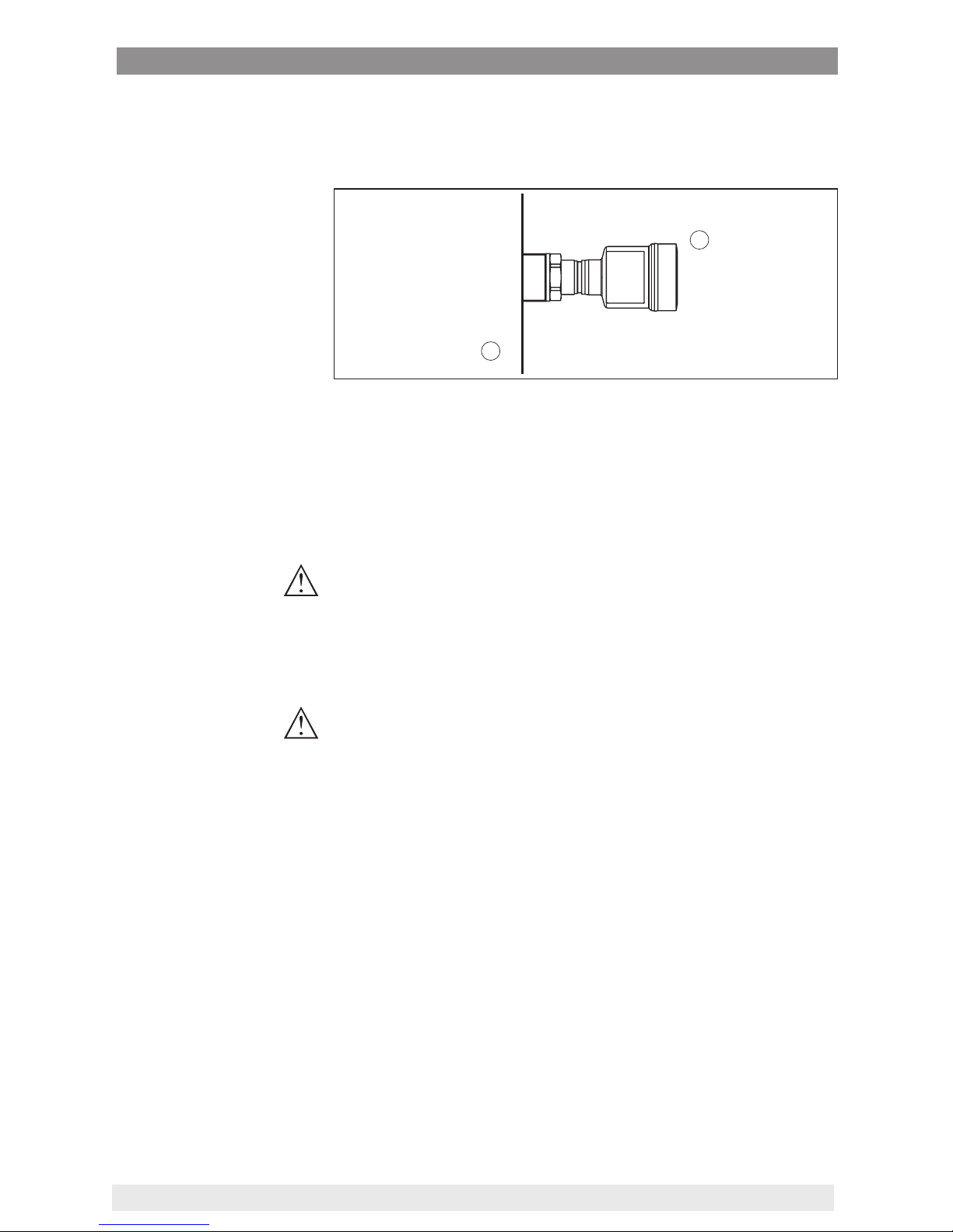
Fig. 24: CPT-2x in IP 68 version 25 bar with axial cable outlet, external housing
1 Transmitter
2 Connection cable
3 External housing
Electronics and terminal
compartment
Overview
1)
Connect screen here. Connect ground terminal on the outside of the housing
to ground as prescribed. The two terminals are galvanically connected.
Page 29

29
5 Connecting to power supply
WIKA Operating Instructions - Process pressure transmitter CPT-2x
1
2
3
5
1
2
( )+(-)
678
4...20m
A
Fig. 25: Electronics and terminal compartment
1 Electronics module
2 Cable gland for voltage supply
3 Cable gland for connection cable, transmitter
1234
6
3
4
1
2
5
Fig. 26: Connection of the sensor in the housing base
1 Yellow
2 White
3 Red
4 Black
5 Shielding
6 Breather capillaries
Electronics and connection compartment for
power supply
Terminal compartment,
housing socket
Page 30

30
5 Connecting to power supply
WIKA Operating Instructions - Process pressure transmitter CPT-2x
5678
4
2
1
connect to Master
Fig. 27: Wiring plan CPT-2x Slave sensor
1 To the Master sensor
2 Ground terminal for connection of the cable screen
2)
5.5 Connection example
5678
4
2
3
1
4
connect to Master
5
1
2
+
( )
(-)
678
4...20mA
Fig. 28: Connection example, electronic dierential pressure
1 Master sensor
2 Slave sensor
3 Connection cable
4 Supply and signal circuit, Master sensor
Connection between master and sensor is carried out according to
the table:
Master sensor Slave sensor
Terminal 5 Terminal 5
Terminal 6 Terminal 6
Terminal 7 Terminal 7
Terminal 8 Terminal 8
Electronics and terminal
compartment
Connection example,
electronicdierential
pressure
2)
Connect screen here. Connect ground terminal on the outside of the housing
to ground as prescribed. The two terminals are galvanically connected.
Page 31

31
6 Functional safety (SIL)
WIKA Operating Instructions - Process pressure transmitter CPT-2x
6 Functional safety (SIL)
6.1 Objective
In case of dangerous failures, processing facilities and machines can
cause risks for persons, environment and property. The risk of such
failures must be judged by the plant operator. Dependent thereon are
measures for risk reduction through error prevention, error detection
and fault control.
The part of plant safety depending on the correct functioning of
safety-related components for risk reduction is called functional
safety. Components used in such safety-instrumented systems (SIS)
must therefore execute their intended function (safety function) with a
dened high probability.
The safety requirements for such components are described in the
international standards IEC 61508 and 61511, which set the standard
for uniform and comparable judgement of instrument and plant (or
machine) safety and hence contribute to worldwide legal certainty.
We distinguish between four safety levels, from SIL1 for low risk to
SIL4 for very high risk (SIL = Safety Integrity Level), depending on the
required degree of risk reduction.
6.2 SILqualication
When developing instruments that can be used in safety-instrument-
ed systems, the focus is on avoiding systematical errors as well as
determining and controlling random errors.
Here are the most important characteristics and requirements from
the perspective of functional safety according to IEC 61508 (Edition 2):
•
Internal monitoring of safety-relevant circuit parts
•
Extended standardization of the software development
•
In case of failure, switching of the safety-relevant outputs to a
dened safe state
•
Determination of the failure probability of the dened safety func-
tion
•
Reliable parameterization with non-safe user environment
•
Proof test
The SIL qualication of components is specied in a manual on func-
tional safety (Safety Manual). Here, you can nd all safety-relevant
characteristics and information the user and the planner need for
planning and operating the safety-instrumented system. This document is attached to each instrument with SIL rating and can be also
found on our homepage via the instrument search.
6.3 Application area
The instrument can be used, for example, for process pressure and
hydrostatic level measurement of liquids in safety-instrumented sys-
Background
Plant safety b
y risk
reduction
Standards and safety
levels
Properties and requirements
Safety Manual
Page 32

32
6 Functional safety (SIL)
WIKA Operating Instructions - Process pressure transmitter CPT-2x
tems (SIS) acc. to IEC 61508 and IEC 61511. Note the specications
in the Safety Manual.
The following inputs/outputs are permitted:
•
4 … 20 mA/HART current output
6.4 Safety concept of the parameterization
The following tools are permitted for parameterization of the safety
function:
•
The integrated display and adjustment unit for on-site adjustment
•
The DTM suitable for the signal conditioning instrument in conjunction with an adjustment software according to the FDT/DTM
standard, e. g. PACTware
Note:
For operation of the CPT-2x an actual DTM Collection is required. The
modication of safety-relevant parameters is only possible with active
connection to the instrument (online mode).
To avoid possible errors during parameterisation in a non-safe operating environment, a verication procedure is used that enables reliable
detection of parameter adjustment errors. The safety-relevant parameters have to be veried after they are saved in the instrument. In
normal operating condition, the instrument is also protected (locked)
against inadvertent or unauthorized parameter changes. This concept
applies to adjustment directly on the instrument as well as adjustment
with PACTware and DTM.
To prevent unintentional or unauthorized adjustment, the set parameters must be protected from unauthorized access. For this reason
the instrument is shipped in locked condition. The PIN in delivery
status is "0000".
When shipped with a specic parameter adjustment, the instruments
are accompanied by a list with the values deviating from the basic
setting.
All safety-relevant parameters must be veried after a change.
The parameter settings of the measurement loop must be document-
ed. You can nd a list of all safety-relevant parameters in the delivery
status in chapter "Setup with the display and adjustment module"
under "Additional adjustments - Reset". In addition, a list of the safetyrelevant parameters can be stored and printed via PACTware/DTM.
For each parameter change, the instrument must be unlocked via a
PIN (see chapter "Setup steps - Lock adjustment"). The device status
is indicated by the symbol of an unlocked or locked padlock.
In delivery status, the PIN is 0000.
Warning:
If adjustment is enabled, the safety function must be considered
as unreliable. This applies until the parameterisation is terminated
Tool for operation and
par
ameteriz
ation
Safe parameterization
Safety-relevant parameters
Unlock adjustment
Unsafe device
status
Page 33

33
6 Functional safety (SIL)
WIKA Operating Instructions - Process pressure transmitter CPT-2x
correctly. If necessary, other measures must be taken to maintain the
safety function.
All parameters changed by the operator are automatically stored
temporarily so that they can be veried in the next step.
After setup, the modied parameters must be veried (conrm the
correctness of the parameters). To do this, you rst have to enter the
PIN. Here the adjustment is locked automatically. Then you carry
out a comparison of two character strings. You must conrm that the
character strings are identical. This is used to check the character
presentation.
Then you conrm that the serial number of your instrument has been
carried over correctly. This is used to check device communication.
Then, all modied parameters that have to be conrmed are listed.
After this process is terminated, the safety function is again ensured.
Warning:
If the described process was not carried out completely or correctly
(e.g. due to interruption or voltage loss), the instrument remains in an
unlocked, and thus unsafe, status.
Warning:
In case of a reset to basic settings, all safety-relevant parameters will
also be reset to default. Therefore all safety-relevant parameters must
be checked or readjusted.
Change parameters
Verify par
ameters/Lock
adjustment
Incomplete process
Instrument reset
Page 34

34
7 Set up with the display and adjustment module
WIKA Operating Instructions - Process pressure transmitter CPT-2x
7 Set up with the display and adjustment
module
7.1 Parameter adjustment
The main menu is divided into ve sections with the following functions:
Setup: Settings, e.g., for measurement loop name, application, units,
position correction, adjustment, signal output
Display: Settings, e.g., for language, measured value display, lighting
Diagnosis: Information, e.g. on instrument status, pointer, measure-
ment certainty, simulation
Additional adjustments: PIN, date/time, reset, copy function
Info: Instrument name, hardware and software version, date of manu-
facture, sensor features
In the main menu item "Setup", the individual submenu items should
be selected one after the other and provided with the correct parameter values.
The following submenu points are available:
In the following section, the menu items from the menu "Setup" for
electronic dierential pressure measurement are described in detail.
Depending on the selected application, dierent sections are relevant.
Information:
Further menu items of the menu "Setup" as well as the complete
menus "Display", "Diagnosis", "Additional adjustments" and "Info"
are described in the operating instructions of the respective master
sensor.
A parameter change with SIL qualied instruments must always be
carried out as follows:
•
Unlock adjustment
•
Change parameters
•
Lock adjustment and verify modied parameters
This ensures that all modied parameters have been deliberately
changed.
Unlock adjustment
The instrument is shipped in locked condition.
Main menu
Operating sequence
Page 35

35
7 Set up with the display and adjustment module
WIKA Operating Instructions - Process pressure transmitter CPT-2x
To prevent unintentional or unauthorized adjustment, the instrument
is protected (locked) against all parameter changes while in normal
operating condition.
For each parameter change you have to enter the PIN of the instrument. In delivery status, the PIN is "0000".
Change parameters
You can nd a description below the respective parameter.
Lockadjustmentandverifymodiedparameters
You can nd a description below the parameter "Setup - Lock adjustment".
In this menu item you activate/deactivate the slave sensor for electronic dierential pressure and select the application.
The CPT-2x in conjunction with a slave sensor can be used for ow,
dierential pressure, density and interface measurement. The default
setting is dierential pressure measurement. Switchover is carried out
in the adjustment menu.
If you have connected a slave sensor, you conrm this with "Activate".
Note:
It is absolutely necessary to activate the slave sensor to have the
applications displayed in the electronic dierential pressure measurement menus.
Enter the requested parameters via the appropriate keys, save your
settings with [OK] and jump to the next menu item with the [ESC] and
the [->] key.
In this menu item, you determine the units for the "Min. adjustment/
Zero" and "Max. adjustment/Span" as well as the static pressure.
If the level should be adjusted in a height unit, the density of the medium must also be entered later during the adjustment.
Setup - Application
Setup - Units
Page 36

36
7 Set up with the display and adjustment module
WIKA Operating Instructions - Process pressure transmitter CPT-2x
In addition, the unit is determined in the menu item "Peak value
temperature".
Enter the requested parameters via the appropriate keys, save your
settings with [OK] and jump to the next menu item with the [ESC] and
the [->] key.
Especially with chemical seal systems, the installation position of the
instrument can shift (oset) the measured value. Position correction
compensates this oset. In the process, the actual measured value
is taken over automatically. With relative pressure measuring cells a
manual oset can also be carried out.
There are the following possibilities for a position correction with a
master/slave combination
•
Automatic correction for both sensors
•
Manual correction for the Master (dierential pressure)
•
Manual correction for the Slave (static pressure)
With a master/slave combination in the application "Density-compen-
sated level measurement" there are the following additional options
for the position correction
•
Automatic correction, master (level)
•
Manual correction for the Master (level)
During an automatic position correction, the current measured value
is accepted as the correction value. This value must not be inuenced/corrupted by product coverage or static pressure.
In case of a manual position correction, the oset value is determined
by the user. Select for this purpose the function "Edit" and enter the
requested value.
Save your settings with [OK] and move with [ESC] and [->] to the
next menu item.
After the position correction is carried out, the actual measured value
is corrected to 0. The corrective value appears with an inverse sign as
oset value in the display.
The position correction can be repeated any number of times.
Setup - Position correction
Page 37

37
7 Set up with the display and adjustment module
WIKA Operating Instructions - Process pressure transmitter CPT-2x
CPT-2x always measures pressure independently of the process variable selected in the menu item "Application". To output the selected
process variable correctly, an allocation of the output signal to 0 %
and 100 % must be carried out (adjustment).
With the application "Level", the hydrostatic pressure, e.g. with full
and empty vessel, is entered for adjustment. A superimposed pressure is detected by the slave sensor and automatically compensated.
See the following example:
2
1
100%
0%
5 m
(196.9
")
4
3
Fig. 29: Parameter adjustment example "Min./max. adjustment, level measurement"
1 Min. level = 0 % corresponds to 0.0 mbar
2 Max. level = 100 % corresponds to 490.5 mbar
3 CPT-2x
4 CPT-2x, slave sensor
If these values are not known, an adjustment with lling levels of e.g.
10 % and 90 % is also possible. By means of these settings, the real
lling height is then calculated.
The actual product level during this adjustment is not important,
because the min./max. adjustment is always carried out without
changing the product level. These settings can be made ahead of
time without the instrument having to be installed.
Note:
If the adjustment ranges are exceeded, the entered value will not be
accepted. Editing can be interrupted with [ESC] or corrected to a
value within the adjustment ranges.
For the other process variables such as e.g. process pressure, dierential pressure or ow, the adjustment is performed in like manner.
Proceed as follows:
Setup - Adjustment
Setup - Min. adjustment
Level
Page 38

38
7 Set up with the display and adjustment module
WIKA Operating Instructions - Process pressure transmitter CPT-2x
1. Select the menu item "Setup" with [->] and conrm with [OK].
Now select with [->] the menu item "Adjustment", then "Min.
adjustment" and conrm with [OK].
2. Edit the percentage value with [OK] and set the cursor to the
requested position with [->].
3. Set the requested percentage value (e.g. 10 %) with [+] and save
with [OK]. The cursor jumps now to the pressure value.
4. Enter the pressure value corresponding to the min. level (e.g.
0 mbar).
5. Save settings with [OK] and move with [ESC] and [->] to the max.
adjustment.
The min. adjustment is nished.
For an adjustment with lling, simply enter the actual measured value
indicated at the bottom of the display.
Proceed as follows:
1. Select with [->] the menu item Max. adjustment and conrm with
[OK].
2. Edit the percentage value with [OK] and set the cursor to the
requested position with [->].
3. Set the requested percentage value (e.g. 90 %) with [+] and save
with [OK]. The cursor jumps now to the pressure value.
4. Enter the pressure value for the full vessel (e.g. 900 mbar) corresponding to the percentage value.
5. Save settings with [OK]
The max. adjustment is nished.
For an adjustment with lling, simply enter the actual measured value
indicated at the bottom of the display.
Proceed as follows:
1. Select the menu item "Setup" with [->] and conrm with [OK].
Now select with [->] the menu item "Min. adjustment" and conrm
with [OK].
2. Edit the mbar value with [OK] and set the cursor to the requested
position with [->].
Setup - Max. adjustment
Lev
el
Setup - Min. adjustment,
ow
Page 39

39
7 Set up with the display and adjustment module
WIKA Operating Instructions - Process pressure transmitter CPT-2x
3. Set the requested mbar value with [+] and store with [OK].
4. Change with [ESC] and [->] to the span adjustment
The min. adjustment is nished.
For an adjustment with pressure, simply enter the actual measured
value indicated at the bottom of the display.
Proceed as follows:
1. Select with [->] the menu item Max. adjustment and conrm with
[OK].
2. Edit the mbar value with [OK] and set the cursor to the requested
position with [->].
3. Set the requested mbar value with [+] and store with [OK].
The max. adjustment is nished.
For an adjustment with pressure, simply enter the actual measured
value indicated at the bottom of the display.
Proceed as follows:
1. Select the menu item "Setup" with [->] and conrm with [OK].
Now select with [->] the menu item "Zero adjustment" and conrm
with [OK].
2. Edit the mbar value with [OK] and set the cursor to the requested
position with [->].
3. Set the requested mbar value with [+] and store with [OK].
4. Change with [ESC] and [->] to the span adjustment
The zero adjustment is nished.
Information:
The Zero adjustment shifts the value of the span adjustment. The
span, i.e. the dierence between these values, however, remains
unchanged.
For an adjustment with pressure, simply enter the actual measured
value indicated at the bottom of the display.
Proceed as follows:
1. Select with [->] the menu item Span adjustment and conrm with
[OK].
Setup - Max. adjustment,
ow
Setup - Zero adjustment,
dierentialpressure
Setup - span adjustment,
dierentialpressure
Page 40

40
7 Set up with the display and adjustment module
WIKA Operating Instructions - Process pressure transmitter CPT-2x
2. Edit the mbar value with [OK] and set the cursor to the requested
position with [->].
3. Set the requested mbar value with [+] and store with [OK].
The span adjustment is nished.
For an adjustment with pressure, simply enter the actual measured
value indicated at the bottom of the display.
Proceed as follows:
. Select in the menu item "Setup" with [->] "Adjustment" and con-
rm with [OK]. Now conrm the menu item "Distance" with [OK].
. Edit the sensor distance with [OK] and set the cursor to the
requested position with [->].
. Set the distance with [+] and save with [OK].
The adjustment of the distance is hence nished.
Proceed as follows:
1. Select the menu item "Setup" with [->] and conrm with [OK].
Now select with [->] the menu item "Min. adjustment" and conrm
with [OK].
2. Edit the percentage value with [OK] and set the cursor to the
requested position with [->].
3. Set the requested percentage value with [+] and save with [OK].
The cursor jumps now to the density value.
4. Enter the min. density corresponding to the percentage value.
5. Save settings with [OK] and move with [ESC] and [->] to the max.
adjustment.
The min. adjustment for density is nished.
Proceed as follows:
1. Select the menu item "Setup" with [->] and conrm with [OK].
Now select with [->] the menu item "Max. adjustment" and con-
rm with [OK].
Setup - Distance, density
Setup - Min. adjustment,
density
Setup - Max.
adjustment,
density
Page 41

41
7 Set up with the display and adjustment module
WIKA Operating Instructions - Process pressure transmitter CPT-2x
2. Edit the percentage value with [OK] and set the cursor to the
requested position with [->].
3. Set the requested percentage value with [+] and save with [OK].
The cursor jumps now to the density value.
4. Enter the max. density value corresponding to the percentage
value.
The max. adjustment for density is nished.
Proceed as follows:
. Select in the menu item "Setup" with [->] "Adjustment" and con-
rm with [OK]. Now conrm the menu item "Distance" with [OK].
. Edit the sensor distance with [OK] and set the cursor to the
requested position with [->].
. Set the distance with [+] and save with [OK].
The adjustment of the distance is hence nished.
Proceed as follows:
1. Select the menu item "Setup" with [->] and conrm with [OK].
Now select with [->] the menu item "Min. adjustment" and conrm
with [OK].
2. Edit the percentage value with [OK] and set the cursor to the
requested position with [->].
3. Set the requested percentage value with [+] and save with [OK].
The cursor jumps now to the height value.
4. Enter the min. height of the interface corresponding to the percentage value.
5. Save settings with [OK] and move with [ESC] and [->] to the max.
adjustment.
The min. adjustment for interface is thus nished.
Proceed as follows:
1. Select the menu item "Setup" with [->] and conrm with [OK].
Now select with [->] the menu item "Max. adjustment" and con-
rm with [OK].
Setup - Distance Interface
Setup - Min. adjustment Inter
face
Setup - Max. adjustment Interface
Page 42

42
7 Set up with the display and adjustment module
WIKA Operating Instructions - Process pressure transmitter CPT-2x
2. Edit the percentage value with [OK] and set the cursor to the
requested position with [->].
3. Set the requested percentage value with [+] and save with [OK].
The cursor jumps now to the height value.
4. Enter the max. height of the interface corresponding to the percentage value.
The max. adjustment for interface is nished.
Proceed as follows:
. Select in the menu item "Setup" with [->] "Adjustment" and con-
rm with [OK]. Now conrm the menu item "Distance" with [OK].
. Edit the sensor distance with [OK] and set the cursor to the
requested position with [->].
. Set the distance with [+] and save with [OK].
The adjustment of the distance is hence nished.
Proceed as follows:
1. Select the menu item "Setup" with [->] and conrm with [OK].
Now select with [->] the menu item "Adjustment", then "Min.
adjustment" and conrm with [OK].
2. Edit the percentage value with [OK] and set the cursor to the
requested position with [->].
3. Set the requested percentage value (e.g. 0 %) with [+] and save
with [OK]. The cursor jumps now to the pressure value.
4. Enter the value corresponding to the min. level (e.g. 0 m).
5. Save settings with [OK] and move with [ESC] and [->] to the max.
adjustment.
The min. adjustment is nished.
For an adjustment with lling, simply enter the actual measured value
indicated at the bottom of the display.
Proceed as follows:
1. Select with [->] the menu item Max. adjustment and conrm with
[OK].
Setup - Distance, level
density-compensated
Setup - Min. distance
, lev-
el density-compensated
Setup - Max. distance,
level density-compensated
Page 43

43
7 Set up with the display and adjustment module
WIKA Operating Instructions - Process pressure transmitter CPT-2x
2. Edit the percentage value with [OK] and set the cursor to the
requested position with [->].
3. Set the requested percentage value (e.g. 100 %) with [+] and
save with [OK]. The cursor jumps now to the pressure value.
4. Enter the value for the full vessel (e.g. 10 m) corresponding to the
percentage value.
5. Save settings with [OK]
The max. adjustment is nished.
For an adjustment with lling, simply enter the actual measured value
indicated at the bottom of the display.
A linearization is necessary for all applications in which the measured
process variable does not increase linearly with the measured value.
This applies for example to the ow measured via the dierential
pressure or the vessel volume measured via the level. Corresponding linearization curves are preprogrammed for such cases. They
represent the correlation between the measured value percentage
and process variable. The linearization applies to the measured value
indication and the current output.
Caution:
Note the following, if the respective sensor is used as part of an overll protection system according to WHG:
If a linearisation curve is selected, the measuring signal is no longer
necessarily linear to the lling height. This must be considered by the
user especially when setting the switching point on the limit signal
transmitter.
Since the parameter adjustment of the Function Block 1 (FB1) is very
comprehensive, it was divided into various submenu items.
In menu item "Channel" you determine the input signal for further
processing in AI FB 1.
As input signals, the output values of Transducer Block (TB) can be
selected.
Setup - Linearisation
Setup - AI FB1
Setup - AI FB1 - Channel
Page 44

44
7 Set up with the display and adjustment module
WIKA Operating Instructions - Process pressure transmitter CPT-2x
With this menu item you safeguard the sensor parameters against
unauthorized or unintentional modications.
To avoid possible errors during parameter adjustment in a non-safe
environment, a verication procedure is used that enables reliable
detection of parameter adjustment errors. In this procedure, safetyrelevant parameters are veried before saving them in the instrument.
In addition, as a protection against unintentional or unauthorized
adjustment, the instrument is locked against all parameter changes in
normal operating condition.
1. Enter PIN
The instrument is shipped in locked conditon. The PIN in the delivery
status is "0000".
2. Character string comparison
You then have to carry out the character string comparison. This is
used to check the character presentation.
Conrm if the two character strings are identical. The verication texts
are provided in German and in the case of all other menu languages,
in English.
3. Serial number acknowledgement
Afterwards you conrm that the serial number of your instrument was
carried over correctly. This is used to check device communication.
4. Verify parameters
All safety-relevant parameters must be veried after a change:
•
SIL parameter 1: Zero adjustment
•
SIL parameter 2: Slave on/o
•
Non-SIL parameter 1: Measured value presentation
•
Non-SIL parameter 2: Display value 1, unit of the application
•
Non-SIL parameter 3: Menu language
•
Non-SIL parameter 4: Lighting
Setup - Lock adjustment
Page 45

45
7 Set up with the display and adjustment module
WIKA Operating Instructions - Process pressure transmitter CPT-2x
Conrm the modied values one after the other.
If the described process of parameter adjustment was run through
completely and correctly, the instrument will be locked and hence
ready for operation.
Otherwise the instrument remains in the released and hence unsafe
condition.
Information:
As long as the CPT-2x is powered, the display and adjustment module remains in the actually set adjustment menu. An automatic, timecontrolled reset to the measured value indication is not carried out.
In this menu item, you dene which measured value is displayed.
The default setting for the displayed value is "Dierential pressure".
In this menu item you dene the number of decimal positions with
which the measured value is displayed.
The default setting for the display format is "Automatic".
The respective min. and max. measured values for the dierential
pressure and static pressure are stored in the sensor. In menu item
"Peak value, pressure", both values are displayed.
In another window you can carry out a reset of the peak values
separately.
In this menu item you can simulate measured values. This allows the
signal path to be tested, e.g. through downstream indicating instruments or the input card of the control system.
Display - Displayed value
1 and 2 - 4 … 20 mA
Display - Display format
1 and 2
Diagnostics - Peak values, pressure
Diagnosis - Simulation
4 … 20 mA/HART
Page 46

46
7 Set up with the display and adjustment module
WIKA Operating Instructions - Process pressure transmitter CPT-2x
Select the requested simulation variable and set the requested value.
To deactivate the simulation, you have to push the [ESC] key and
conrm the message "Deactivate simulation" with the [OK] key.
Caution:
During simulation, the simulated value is outputted as 4 … 20 mA current value and as digital HART signal. The status message within the
context of the asset management function is "Maintenance".
Note:
Without manual deactivation, the sensor terminates the simulation
automatically after 60 minutes.
In menu item "Current output, variable" you specify which measured
variable is outputted via the current output.
The following selection is possible depending on the selected application:
•
Flow
•
Height - Interface
•
Density
•
Dierential pressure
•
Static pressure
•
Percent
•
Scaled
•
Percent linearized
•
Measuring cell temperature (ceramic measuring cell)
•
Electronics temperature
In this menu item, the units for the DP ow element are determined
and the selection of mass or volume ow is carried out.
Furthermore the adjustment for the volume or mass ow rate at 0 % or
100 % is carried out.
Additional settings - Current output 1 and 2 (size)
Additional adjustments
- Characteristics values,
DPowelement
Page 47

47
8 Diagnosis, asset management and service
WIKA Operating Instructions - Process pressure transmitter CPT-2x
8 Diagnosis, asset management and service
8.1 Maintenance
If the device is used properly, no special maintenance is required in
normal operation.
In some applications, product buildup on the diaphragm can inuence
the measuring result. Depending on the sensor and application, take
precautions to ensure that heavy buildup, and especially a hardening
thereof, is avoided.
To identify possible undetected, dangerous failures, the safety func-
tion of the instrument must be checked in adaquate intervals by a
proof test.
During the function test, the safety function must be treated as unsafe.
Keep in mind that the function test inuences downstream connected
devices.
If one of the tests proves negative, the entire measuring system must
be switched out of service and the process held in a safe state by
means of other measures.
You can nd detailed information on the proof test in the Safety
Manual (SIL).
8.2 Cleaning - hygienic connection with
compression nut
The hygienic connection with compression nut can be disassembled
and the diaphragm cleaned.
The following graphic shows the structure:
4
3
2
1
5
6
7
Fig. 30: CPT-2x, structure of the hygienic connection with compression nut
1 Hexagon
2 Compression nut
3 Process tting
4 Process module
5 Form seal for the measuring cell
6 O-ring seal for the process tting
7 Diaphragm
To do so, proceed as follows:
Maintenance
Proof test
Overview
Procedure
Page 48

48
8 Diagnosis, asset management and service
WIKA Operating Instructions - Process pressure transmitter CPT-2x
1. Loosen compression nut and remove the pressure transmitter
from the welded socket
2. Remove the O-ring seal for the process tting
3. Clean the diaphragm with brass brush and cleaning detergent
4. Loosen the hexagon and remove the process component from
the process tting
5. Remove the form seal for the measuring cell and remove it by a
new one
6. Screw the process component into the process tting, tighten the
hexagon (wrench size see chapter "Dimensions", max. torque see
chapter "Technical data")
7. Insert new O-ring seal for the process tting
8. Install the process pressure transmitter in the welded socket,
tighten compression nut
The cleaning is nished.
The pressure transmitter is directly ready for operation, a fresh adjust-
ment is not required.
8.3 Rectify faults
The operator of the system is responsible for taking suitable measures to rectify faults.
The rst measures are:
•
Evaluation of fault messages via the adjustment device
•
Checking the output signal
•
Treatment of measurement errors
Further comprehensive diagnostics options are available with a PC
with PACTware and the suitable DTM. In many cases, the reasons can
be determined in this way and faults rectied.
Depending on the reason for the fault and the measures taken, the
steps described in chapter "Setup" must be carried out again or must
be checked for plausibility and completeness.
8.4 Exchange process module on version
IP 68 (25 bar)
On version IP 68 (25 bar), the user can exchange the process module
on site. Connection cable and external housing can be kept.
Required tools:
•
Hexagon key wrench, size 2
Caution:
The exchange may only be carried out in the complete absence of
line voltage.
In Ex applications, only a replacement part with appropriate Ex approval may be used.
Reaction when malfunction occurs
Procedur
e for fault recti-
cation
Reaction after fault recti-
cation
Page 49

49
8 Diagnosis, asset management and service
WIKA Operating Instructions - Process pressure transmitter CPT-2x
Caution:
During exchange, protect the inner side of the parts against contamination and moisture.
Proceed as follows when carrying out the exchange:
1. Losen the xing screw with the hexagon key wrench
2. Carefully detach the cable assembly from the process module
1
2
3
64
5
Fig. 31: CPT-2x in IP 68 version, 25 bar and lateral cable outlet, external housing
1 Process module
2 Plug connector
3 Fixing screw
4 Cable assembly
5 Connection cable
6 External housing
3. Loosen the plug connector
4. Mount the new process module on the measuring point
5. Plug the connector back in
6. Mount the cable assembly on the process module and turn it to
the desired position
7. Tighten the xing screw with the hexagon key wrench
The exchange is nished.
If there is no replacement part available on site, one can be ordered
from the agency serving you.
The necessary serial number can be found on the type label of the
instrument or on the delivery note.
8.5 Instrument repair
You can nd information for a return shipment under "Service" on our
local website.
If a repair is necessary, please proceed as follows:
•
Complete one form for each instrument
Page 50

50
8 Diagnosis, asset management and service
WIKA Operating Instructions - Process pressure transmitter CPT-2x
•
If necessary, state a contamination
•
Clean the instrument and pack it damage-proof
•
Attach the completed form and possibly also a safety data sheet to
the instrument
Page 51

51
9 Dismount
WIKA Operating Instructions - Process pressure transmitter CPT-2x
9 Dismount
9.1 Dismounting steps
Warning:
Before dismounting, be aware of dangerous process conditions such
as e.g. pressure in the vessel or pipeline, high temperatures, corrosive or toxic products etc.
Take note of chapters "Mounting" and "Connecting to power supply"
and carry out the listed steps in reverse order.
9.2 Disposal
The instrument consists of materials which can be recycled by specialised recycling companies. We use recyclable materials and have
designed the electronics to be easily separable.
Correct disposal avoids negative eects on humans and the environment and ensures recycling of useful raw materials.
Materials: see chapter "Technical data"
If you have no way to dispose of the old instrument properly, please
contact us concerning return and disposal.
WEEE directive 2012/19/EU
This instrument is not subject to the WEEE directive 2012/19/EU and
the respective national laws. Pass the instrument directly on to a specialised recycling company and do not use the municipal collecting
points. These may be used only for privately used products according
to the WEEE directive.
Page 52

52
10 Supplement
WIKA Operating Instructions - Process pressure transmitter CPT-2x
10 Supplement
10.1 Technical data
Note for approved instruments
The technical data in the respective safety instructions are valid for approved instruments (e.g. with
Ex approval). These data can dier from the data listed herein, for example regarding the process
conditions or the voltage supply.
Materials and weights
Materials, wetted parts
Process tting
316L, PVDF, Alloy C22 (2.4602), Alloy C276 (2.4819),
Duplex (1.4462), Titanium Grade 2
Diaphragm Sapphire-ceramic
®
(> 99.9 % Al2O3 ceramic)
Joining material, diaphragm/base element of measuring cell
Glass (with double and form seal, non-wetted parts)
Measuring cell seal
FKM (VP2/A, A+P 70.16), EPDM (A+P 75.5/KW75F),
FFKM (Kalrez 6375, Perlast G75S, Perlast G75B)
Seal for process tting (in the scope of delivery)
Ʋ Thread G½, EN 837 Klingersil C-4400
Ʋ Thread G1½, DIN 3852-A Klingersil C-4400
Ʋ Hygienic connection with compres-
sion nut
FKM, EPDM, FFKM, FEPM
Ʋ M44 x 1.25 (DIN 13), M30 x 1.5 FKM, FFKM, EPDM
Materialsforapplicationsinfoodstus
Surface quality, hygienic ttings, typ.
Ʋ Process tting Ra < 0.8 µm
Ʋ Ceramic diaphragm Ra < 0.5 µm
Seal below wall mounting plate with 3A
approval
EPDM
Materials, non-wetted parts
Housing
Ʋ Plastic housing Plastic PBT (Polyester)
Ʋ Aluminium die-cast housing Aluminium die-casting AlSi10Mg, powder-coated - basis:
Polyester
Ʋ Stainless steel housing 316L
Ʋ Cable gland PA, stainless steel, brass
Ʋ Sealing, cable gland NBR
Ʋ Blind plug, cable gland PA
Ʋ Seal between housing and housing lid Silicone SI 850 R, NBR silicone-free
Ʋ Inspection window in housing cover Polycarbonate, UL746-C listed (with Ex-d version: glass)
Ʋ Ground terminal 316L
External housing
Ʋ Housing Plastic PBT (Polyester), 316L
Page 53

53
10 Supplement
WIKA Operating Instructions - Process pressure transmitter CPT-2x
Ʋ Socket, wall mounting plate Plastic PBT (Polyester), 316L
Ʋ Seal between base and wall mounting
plate
EPDM (xed connected)
Inspection window in housing cover Polycarbonate, UL746-C listed (with Ex-d version: glass)
Seal between housing and housing lid
Silicone SI 850 R, NBR silicone-free, EPDM (coating-
compatible)
Ground terminal 316Ti/316L
Connection cable to the master sensor PE, PUR
Weights
Total weight CPT-2x approx.
0.8 … 8 kg (1.764 … 17.64 lbs), depending on process
tting and housing
Torques
Max. torque for process tting
Ʋ G½, G¾ 30 Nm (22.13 lbf ft)
Ʋ Fittings according to 3A with ex-
changeable sealing
20 Nm (14.75 lbf ft)
Ʋ Hygienic tting with compression nut
(hexagon)
40 Nm (29.50 lbf ft)
Ʋ G1, M30 x 1.5 50 Nm (36.88 lbf ft)
Ʋ G1 for PASVE 100 Nm (73.76 lbf ft)
Ʋ G1½ 200 Nm (147.5 lbf ft)
Max. torque for screws
Ʋ PMC 1", PMC 1¼" 2 Nm (1.475 lbf ft)
Ʋ PMC 1½" 5 Nm (3.688 lbf ft)
Max. torque for NPT cable glands and Conduit tubes
Ʋ Plastic housing 10 Nm (7.376 lbf ft)
Ʋ Aluminium/Stainless steel housing 50 Nm (36.88 lbf ft)
Input variable
The specications are only an overview and refer to the measuring cell. Limitations due to the
material and version of the process tting as well as the selected pressure type are possible. The
specications on the nameplate apply.
Nominal measuring ranges and overload capability in bar/kPa
Nominal range Overload capacity, max. pressure Overload capacity, min. pressure
Gauge pressure
0 … +0.025 bar/0 … +2.5 kPa
(only for measuring cell ø 28 mm)
+5 bar/+500 kPa -0.05 bar/-5 kPa
0 … +0.1 bar/0 … +10 kPa +15 bar/+1500 kPa -0.2 bar/-20 kPa
0 … +0.4 bar/0 … +40 kPa +30 bar/+3000 kPa -0.8 bar/-80 kPa
0 … +1 bar/0 … +100 kPa +35 bar/+3500 kPa -1 bar/-100 kPa
Page 54

54
10 Supplement
WIKA Operating Instructions - Process pressure transmitter CPT-2x
Nominal range Overload capacity, max. pressure Overload capacity, min. pressure
0 … +2.5 bar/0 … +250 kPa +50 bar/+5000 kPa -1 bar/-100 kPa
0 … +5 bar/0 … +500 kPa +65 bar/+6500 kPa -1 bar/-100 kPa
0 … +10 bar/0 … +1000 kPa +90 bar/+9000 kPa -1 bar/-100 kPa
0 … +25 bar/0 … +2500 kPa +125 bar/+12500 kPa -1 bar/-100 kPa
0 … +60 bar/0 … +6000 kPa +200 bar/+20000 kPa -1 bar/-100 kPa
0 … +100 bar/0 … +10000 kPa
(only for measuring cell ø 28 mm)
+200 bar/+20000 kPa -1 bar/-100 kPa
-1 … 0 bar/-100 … 0 kPa +35 bar/+3500 kPa -1 bar/-100 kPa
-1 … +1.5 bar/-100 … +150 kPa +40 bar/+4000 kPa -1 bar/-100 kPa
-1 … +10 bar/-100 … +1000 kPa +90 bar/+9000 kPa -1 bar/-100 kPa
-1 … +25 bar/-100 … +2500 kPa +125 bar/+12500 kPa -1 bar/-100 kPa
-1 … +60 bar/-100 … +6000 kPa +180 bar/+18000 kPa -1 bar/-100 kPa
-1 … +100 bar/-100 … +10000 kPa
(only for measuring cell ø 28 mm)
+200 bar/+20000 kPa -1 bar/-100 kPa
-0.05 … +0.05 bar/-5 … +5 kPa +7.5 bar/+750 kPa -0.2 bar/-20 kPa
-0.2 … +0.2 bar/-20 … +20 kPa +20 bar/+2000 kPa -0.4 bar/-40 kPa
-0.5 … +0.5 bar/-50 … +50 kPa +35 bar/+3500 kPa -1 bar/-100 kPa
Absolute pressure
0 … 0.1 bar/0 … 10 kPa 15 bar/1500 kPa 0 bar abs.
0 … 1 bar/0 … 100 kPa 35 bar/3500 kPa 0 bar abs.
0 … 2.5 bar/0 … 250 kPa 50 bar/5000 kPa 0 bar abs.
0 … +5 bar/0 … +500 kPa 65 bar/+6500 kPa 0 bar abs.
0 … 10 bar/0 … 1000 kPa 90 bar/9000 kPa 0 bar abs.
0 … 25 bar/0 … 2500 kPa +125 bar/+12500 kPa 0 bar abs.
0 … 60 bar/0 … 6000 kPa +200 bar/+20000 kPa 0 bar abs.
0 … +100 bar/0 … +10000 kPa
(only for measuring cell ø 28 mm)
200 bar/20000 kPa 0 bar abs.
Nominal measuring ranges and overload capacity in psi
Nominal range Overload capacity, max. pressure Overload capacity, min. pressure
Gauge pressure
0 … +0.4 psig
(only for measuring cell ø 28 mm)
+75 psig -0.725 psig
0 … +1.5 psig +225 psig -2.901 psig
0 … +5 psig +375 psig -11.60 psig
0 … +15 psig +525 psig -14.51 psig
0 … +30 psig +600 psig -14.51 psig
0 … +75 psig +975 psig -14.51 psig
Page 55

55
10 Supplement
WIKA Operating Instructions - Process pressure transmitter CPT-2x
Nominal range Overload capacity, max. pressure Overload capacity, min. pressure
0 … +150 psig +1350 psig -14.51 psig
0 … +300 psig +1500 psig -14.51 psig
0 … +900 psig +2900 psig -14.51 psig
0 … +1450 psig
(only for measuring cell ø 28 mm)
+2900 psig -14.51 psig
-14.5 … 0 psig +525 psig -14.51 psig
-14.5 … +20 psig +600 psig -14.51 psig
-14.5 … +75 psig +975 psig -14.51 psig
-14.5 … +150 psig +1350 psig -14.51 psig
-14.5 … +300 psig +1500 psig -14.51 psig
-14.5 … +900 psig +2700 psig -14.51 psig
-14.5 … +1500 psig
(only for measuring cell ø 28 mm)
+2900 psig -14.51 psig
-0.7 … +0.7 psig +105 psig -2.901 psig
-3 … +3 psig +300 psi -5.800 psig
-7 … +7 psig +490 psig -14.51 psig
Absolute pressure
0 … 1.5 psi 225 psig 0 psi
0 … 5 psi 435 psi 0 psi
0 … 15 psi 525 psi 0 psi
0 … 30 psi 600 psi 0 psi
0 … +75 psi 975 psi 0 psi
0 … 150 psi 1350 psi 0 psi
0 … 300 psi 1500 psi 0 psi
0 … 900 psi +2900 psig 0 psi
0 … +1450 psig
(only for measuring cell ø 28 mm)
2900 psig 0 psi
Adjustment ranges
Specications refer to the nominal measuring range, pressure values lower than -1 bar cannot be
set
Level (min./max. adjustment)
Ʋ Percentage value -10 … 110 %
Ʋ Pressure value -120 … 120 %
Flow (min./max. adjustment)
Ʋ Percentage value 0 or 100 % x
Ʋ Pressure value -120 … 120 %
Dierential pressure (zero/span adjustment)
Ʋ Zero -95 … +95 %
Page 56

56
10 Supplement
WIKA Operating Instructions - Process pressure transmitter CPT-2x
Ʋ Span -120 … +120 %
Density (min./max. adjustment)
Ʋ Percentage value -10 … 100 %
Ʋ Density value according to the measuring ranges in kg/dm
3
Interface (min./max. adjustment)
Ʋ Percentage value -10 … 100 %
Ʋ Level value according to the measuring ranges in m
Max. permissible Turn Down
Unlimited (recommended 20 : 1)
Max. permissible turn down with SIL
applications
10 : 1
Dynamic behaviour output
Dynamic characteristics depending on medium and temperature
90 %
100 %
10 %
t
t
T
A
t
t
S
2
1
Fig. 32: Behaviour in case of sudden change of the process variable. tT: dead time; tA: rise time; tS: jump response
time
1 Process variable
2 Output signal
CPT-2x CPT-2x - IP 68 (25 bar)
Dead time ≤ 25 ms ≤ 50 ms
Rise time (10 … 90 %) ≤ 55 ms ≤ 150 ms
Step response time (ti: 0 s, 10 … 90 %) ≤ 80 ms ≤ 200 ms
Damping (63 % of the input variable) 0 … 999 s, adjustable via menu item "Damping"
Referenceconditionsandinuencingvariables(accordingtoDINEN60770-1)
Reference conditions according to DIN EN 61298-1
Ʋ Temperature +15 … +25 °C (+59 … +77 °F)
Ʋ Relative humidity 45 … 75 %
Ʋ Air pressure 860 … 1060 mbar/86 … 106 kPa (12.5 … 15.4 psig)
Determination of characteristics Limit point adjustment according to IEC 61298-2
Page 57

57
10 Supplement
WIKA Operating Instructions - Process pressure transmitter CPT-2x
Characteristic curve Linear
Reference installation position upright, diaphragm points downward
Inuence of the installation position
< 0.2 mbar/20 Pa (0.003 psig)
Deviation in the current output due to
strong, high-frequency electromagnetic
elds acc. to EN 61326
< ±150 µA
Deviation (according to IEC 60770)
Specications refer to the set span. Turn down (TD) is the ratio: nominal measuring range/set span.
Accuracy class Non-linearity, hysteresis and re-
peatability with TD 1 : 1 up to 5 : 1
Non-linearity, hysteresis and repeatability with 5 : 1
0.05 % < 0.05 % < 0.01 % x TD
0.1 % < 0.1 % < 0.02 % x TD
0.2 % < 0.2 % < 0.04 % x TD
Inuenceoftheproducttemperature
Thermal change zero signal and output span through product temperature
Refers to the set span. Turn down (TD) is the ratio: nominal measuring range/set span.
The thermal change of the zero signal and output span corresponds to the temperature error F
T
in
chapter "Calculation of the total deviation (according to DIN 16086)".
Basic temperature error F
T
(
F
TBasis
Fig. 33: Basic temperature error F
TBasis
at TD 1 : 1
The basic temperature error in % from the above graphic can increase due to the additional factors,
depending on the measuring cell version (factor FMZ) and the Turn Down (factor FTD). The additional factors are listed in the following tables.
Page 58

58
10 Supplement
WIKA Operating Instructions - Process pressure transmitter CPT-2x
Additional factor through measuring cell version
Measuring cell version
Measuring cell standard, depending on the accuracy class
0.05 %, 0.1 % 0.2 % (with measuring
range 0.1 bar
abs
)
0.2 %
0.05 %, 0.1 % with measuring range 25 mbar
Factor FMZ 1 2 3
Additional factor through Turn Down
The additional factor FTD through Turn down is calculated according to the following formula:
F
TD
= 0.5 x TD + 0.5
In the table, example values for typical Turn downs are listed.
Turn Down TD 1 : 1 TD 2.5 : 1 TD 5 : 1 TD 10 : 1 TD 20 : 1
Factor FTD 1 1.75 3 5.5 10.5
Long-term stability (according to DIN 16086)
Applies to the respective digital signal output (e.g. HART, Probus PA) as well as to analogue current output 4 … 20 mA under reference conditions. Specications refer to the set span. Turn down
(TD) is the ratio nominal measuring range/set span.
Long-term stability zero signal and output span
Time period
Measuring cell ø 28 mm Measuring cell ø 17.5 mm
All measuring ranges Measuring range
0 … +0.025 bar
(0 … +2.5 kPa)
Allprocessttings ProcessttingG½
(ISO 228-1)
One year < 0.05 % x TD < 0.1 % x TD < 0.1 % x TD < 0.25 % x TD
Five years < 0.1 % x TD < 0.2 % x TD < 0.2 % x TD < 0.5 % x TD
Ten years < 0.2 % x TD < 0.4 % x TD < 0.4 % x TD < 1 % x TD
Process conditions
Process temperature
3)
Measuring cell seal Sensor version
Standard Extended temperature range
FKM VP2/A
-20 … +130 °C (-4 … +266 °F) -20 … +150 °C (-4 … +302 °F)
A+P 70.16 -40 … +130 °C (-40 … +266 °F) -
Endura V91A
-40 … +130 °C (-40 … +266 °F) -40 … +150 °C (-40 … +302 °F)
ET 7067 -20 … +130 °C (-4 … +266 °F) -
V70SW -
-10 … +150 °C (14 … +302 °F)
3)
With process tting PVDF, process temperature max. 100 °C (212 °F).
Page 59

59
10 Supplement
WIKA Operating Instructions - Process pressure transmitter CPT-2x
Measuring cell seal Sensor version
Standard Extended temperature range
EPDM A+P 75.5/KW75F
-40 … +130 °C (-40 … +266 °F) -40 … +150 °C (-40 … +302 °F)
ET 7056 -40 … +130 °C (-40 … +266 °F) -
E70Q -
-40 … +150 °C (-40 … +302 °F)
Fluoraz SD890 -5 … +130 °C (-22 … +266 °F) -
FFKM Kalrez 6375
-20 … +130 °C (-4 … +266 °F) -20 … +150 °C (-4 … +302 °F)
Perlast G75S -15 … +130 °C (-4 … +266 °F) -15 … +150 °C (5 … +302 °F)
Perlast G75B -15 … +130 °C (-4 … +266 °F) -15 … +150 °C (5 … +302 °F)
Perlast G92E -15 … +130 °C (-4 … +266 °F) -15 … +150 °C (5 … +302 °F)
Chemraz 535 -30 … +130 °C (-22 … +266 °F) -
Temperature derating
1
2
0 °C
(32 °F)
-40 °C
(-104 °F)
55 °C
(131 °F)
80 °C
(176 °F)
130 °C
(266 °F)
100 °C
(212 °F)
-40 °C
(-104 °F)
Fig. 34: Temperature derating CPT-2x, version up to +130 °C (+266 °F)
1 Process temperature
2 Ambient temperature
1
2
0 °C
(32 °F)
-40 °C
(-104 °F)
50 °C
(122 °F)
80 °C
(176 °F)
150 °C
(302 °F)
100 °C
(212 °F)
-40 °C
(-104 °F)
Fig. 35: Temperature derating CPT-2x, version up to +150 °C (+302 °F)
1 Process temperature
2 Ambient temperature
Page 60

60
10 Supplement
WIKA Operating Instructions - Process pressure transmitter CPT-2x
SIP process temperature (SIP = Sterilization in place)
Applies to instruments congurations suitable for vapour, i.e. material measuring cell seal EPDM or
FFKM (Perlast G75S).
Vapour stratication up to 2 h +150 °C (+302 °F)
Process pressure
Permissible process pressure See specication "process pressure" on the type label
Mechanical stress
4)
Vibration resistance 4 g at 5 … 200 Hz according to EN 60068-2-6 (vibration
with resonance)
Shock resistance
50 g, 2,3 ms according to EN 60068-2-27 (mechanical
shock)
5)
Ambient conditions
Version Ambient temperature Storage and transport temper-
ature
Standard version
-40 … +80 °C (-40 … +176 °F) -60 … +80 °C (-76 … +176 °F)
Version IP 66/IP 68 (1 bar) -20 … +80 °C (-4 … +176 °F) -20 … +80 °C (-4 … +176 °F)
Version IP 68 (25 bar) with connection cable PUR
-20 … +80 °C (-4 … +176 °F) -20 … +80 °C (-4 … +176 °F)
Version IP 68 (25 bar), connection
cable PE
-20 … +60 °C (-4 … +140 °F) -20 … +60 °C (-4 … +140 °F)
Electromechanical data - version IP 66/IP 67 and IP 66/IP 68 (0.2 bar)
6)
Options of the cable entry
Ʋ Cable entry M20 x 1.5; ½ NPT
Ʋ Cable gland M20 x 1.5; ½ NPT (cable ø see below table)
Ʋ Blind plug M20 x 1.5; ½ NPT
Ʋ Closing cap ½ NPT
Material cable gland/Seal
insert
Cable diameter
5 … 9 mm 6 … 12 mm 7 … 12 mm
PA/NBR ● ● –
Brass nickel-plated/NBR ● ● –
Stainless steel/NBR – – ●
Wire cross-section (spring-loaded terminals)
Ʋ Massive wire, stranded wire 0.2 … 2.5 mm² (AWG 24 … 14)
Ʋ Stranded wire with end sleeve 0.2 … 1.5 mm² (AWG 24 … 16)
4)
Depending on the instrument version.
5)
2 g with housing version stainless steel double chamber
6)
IP 66/IP 68 (0.2 bar), only with absolute pressure.
Page 61

61
10 Supplement
WIKA Operating Instructions - Process pressure transmitter CPT-2x
Electromechanical data - version IP 68 (25 bar)
Connection cable transmitter - external housing, mechanical data
Ʋ Conguration Wires, strain relief, breather capillaries, screen braiding,
metal foil, mantle
7)
Ʋ Standard length 5 m (16.40 ft)
Ʋ Max. length 180 m (590.5 ft)
Ʋ Min. bending radius at 25 °C/77 °F 25 mm (0.985 in)
Ʋ Diameter approx. 8 mm (0.315 in)
Ʋ Colour PE Black
Ʋ Colour PUR Blue
Connection cable transmitter - external housing, electrical data
Ʋ Wire cross-section 0.5 mm² (AWG 20)
Ʋ Wire resistance R
´
0.037 Ω/m (0.012 Ω/ft)
Interface to the Master sensor
Data transmission Digital (I²C-Bus)
Connection cable Slave - Master, mechanical data
Ʋ Conguration four wires, one suspension cable, braiding, metal foil,
cover
Ʋ Standard length 5 m (16.40 ft)
Ʋ Max. length 25 m (82.02 ft)
Ʋ Min. bending radius at 25 °C/77 °F 25 mm (0.985 in)
Ʋ Diameter approx. 8 mm (0.315 in)
Ʋ Material PUR
Ʋ Colour Black
Connection cable Slave - Master, electrical data
Ʋ Wire cross-section 0.34 mm² (AWG 22)
Ʋ Wire resistance < 0.05 Ω/m (0.015 Ω/ft)
Voltage supply for the complete system through Master
Operating voltage
Ʋ U
B min
12 V DC
Ʋ U
B min
- lighted display and adjustment
module
16 V DC
Ʋ U
B max
Depending on signal output and version of the master
sensor
Potential connections and electrical separating measures in the instrument
Electronics Not non-oating
Ground terminal Galvanically connected with the metal process tting
7)
Breather capillaries not with Ex-d version.
Page 62

62
10 Supplement
WIKA Operating Instructions - Process pressure transmitter CPT-2x
Galvanic separation between electronics and metal housing parts
Ʋ Reference voltage 500 V AC
Electrical protective measures
8)
Housing material Version Protection acc. to
IEC 60529
Protection acc. to NEMA
Plastic Single chamber
IP 66/IP 67 Type 6P
Aluminium Single chamber IP 66/IP 67
IP 66/IP 68 (0.2 bar)
Type 6P
Type 6P
Stainless steel (electropolished)
Single chamber
Single chamber
IP 66/IP 67
IP 69K
Type 6P
-
Stainless steel (precision
casting)
Single chamber
IP 66/IP 67
IP 66/IP 68 (0.2 bar)
Type 6P
Type 6P
Stainless steel Transmitter for external
housing
IP 68 (25 bar) -
Altitude above sea level
Ʋ by default up to 2000 m (6562 ft)
Ʋ with connected overvoltage protection
on the master sensor
up to 5000 m (16404 ft)
Pollution degree
9)
4
Protection rating (IEC 61010-1) II
Approvals
Instruments with approvals can have deviating technical data (depending on the version). For such
instruments, the corresponding approval documents must be noted.
10.2 Calculation of the total deviation
The total deviation of a pressure transmitter indicates the maximum measurement error to be expected in practice. It is also called maximum practical deviation or operational error.
According to DIN 16086, the total deviation F
total
is the sum of the basic accuracy F
perf
and the long-
term stability F
stab
:
F
total
= F
perf
+ F
stab
The basic accuracy F
perf
consists of the thermal change of the zero signal and the output span FT as
well as the deviation FKl:
F
perf
= √((FT)2 + (FKl)2)
The thermal change of zero signal and output span F
T
is specied in chapter "Technical data". The
basic temperature error FT is shown in a graphic. Depending on the measuring cell version and Turn
down, this value must be multiplied with the additional factors FMZ and FTD:
F
T
x FMZ x FTD
Also these values are specied in chapter "Technical data".
This applies for a digital signal output through HART, Probus PA or Foundation Fieldbus.
8)
Protection rating IP 66/IP 68 (0.2 bar) only in conjunction with absolute pressure.
9)
When used with fullled housing protection.
Page 63

63
10 Supplement
WIKA Operating Instructions - Process pressure transmitter CPT-2x
With a 4 … 20 mA output, the thermal change of the current output Fa must be added:
F
perf
= √((FT)2 + (FKl)2 + (Fa)2)
To provide a better overview, the formula symbols are listed together below:
•
F
total
: Total deviation
•
F
perf
: Basic accuracy
•
F
stab
: Long-term stability
•
FT: Thermal change of zero signal and output span (temperature error)
•
FKl: Deviation
•
Fa: Thermal change of the current output
•
FMZ: Additional factor measuring cell version
•
FTD: Additional factor Turn down
10.3 Practical example
Data
Level measurement in a small vessel, 500 mm height corresponds to 0.049 bar (4.9 KPa), superimposed pressure 0.35 bar (35 KPa), medium temperature 40 °C
CPT-2x Master and slave sensor each with nominal measuring range 0.4 bar (40 KPa), deviation
< 0.1 %, process tting G1½ (measuring cell ø 28 mm)
The required values for the temperature error FT, deviation FKl and long-term stability F
stab
are avail-
able in the technical data.
1. Calculation of the Turn down
TD = 0.4 bar/0.049 bar, TD = 8.2 : 1
2. Determination temperature error F
T
The temperature error FT consists of the basic temperature error F
TBasis
, the additional factor meas-
uring cell FMZ and the additional factor Turn Down FTD.
50
(
F
TBasis
Fig. 36: Determination of the basic temperature error for the above example: F
TBasis
= 0.15 %
Measuring cell version
Measuring cell standard, depending on the accuracy class
0.05 %, 0.1 % 0.2 % (0.1 bar
abs
) 0.2 %
Factor FMZ 1 2 3
Page 64

64
10 Supplement
WIKA Operating Instructions - Process pressure transmitter CPT-2x
Tab. 13: Determination of the additional factor measuring cell for above example: FMZ = 1
The additional factor FTD through Turn down is calculated according to the following formula:
F
TD
= 0.5 x TD + 0.5, with TD = 8.2:1 of above calculation
F
TD
= 0.5 x 8.2 + 0.5 = 4.6
Determination of the temperature error master sensor for above example:
F
T
= F
TBasis
x FMZ x F
TD
FT = 0.15 % x 1 x 4.6
F
T
= 0.69 %
The temperature error of each sensor is hence 0.69 %
3. Determination of deviation and long-term stability
Accuracy class Non-linearity, hysteresis and non-repeatability
TD≤5:1 TD > 5 : 1
0.05 % < 0.05 % < 0.01 % x TD
0.1 % < 0.1 % < 0.02 % x TD
0.2 % < 0.2 % < 0.04 % x TD
Tab. 14: Determination of the deviation FKl from the table with accuracy class 0.1 %: FKl = 0.02 % x TD =
0.02 % x 8.2 = 0.16 %
Time period
Measuring cell ø 28 mm Measuring cell ø 17.5 mm
All measuring ranges Measuring range
0 … +0.025 bar
(0 … +2.5 kPa)
Allprocessttings ProcessttingG½
(ISO 228-1)
One year < 0.05 % x TD < 0.1 % x TD < 0.1 % x TD < 0.25 % x TD
Five years < 0.1 % x TD < 0.2 % x TD < 0.2 % x TD < 0.5 % x TD
Ten years < 0.2 % x TD < 0.4 % x TD < 0.4 % x TD < 1 % x TD
Tab. 15: Determination of the long-term stability F
stab
from the table, consideration for one year: F
stab
= 0.05 % x TD
= 0.05 % x 8.2 = 0.41 %
4. Calculation of the total deviation
- 1. step: Basic accuracy F
perf
F
perf
= √((FT)2 + (FKl)2)
F
T
= 0.69 %
FKl= 0.16 % (calculation of above table)
F
perf
= √(0.69 %)2 + (0.16 %)2)
F
perf
= 0.71 %
- 2. step: Total deviation F
total
F
total
= F
perf
+ F
stab
F
perf
= 0.71 % (result of step 1)
F
stab
= 0.41 % (calculation of above table)
F
total
= 0.71 % + 0.41 % = 1.12 %
The total deviation of each sensor is hence 1.12 %.
Page 65

65
10 Supplement
WIKA Operating Instructions - Process pressure transmitter CPT-2x
5. Calculation of the total deviation of the measuring system
Both sensors are included in the calculation of the total deviation of the measurig system. With
4 … 20 mA master sensors the thermal error of the analogue output is also added:
F
total
= √(F
total-Master
)2 + (F
total-Slave
)2 + (Fa)
2
0,3 %
-0,15 %
-40°C -20°C
20°C
40°C 60°C 80°C
0,15 %
-0,3 %
Fig. 37: Fa through thermal change current output, in this example = 0.1 %
F
total
= √(1.12 %)2 + (1.12 %)2 + (0.1 %)2)= 1.6 %
The total deviation of the measuring system is hence 1.6 %.
Deviation in mm: 1.6 % of 500 mm = 7.9 mm
The example shows that the measurement error in practice can be considerably higher than the
basic accuracy. Reasons are temperature inuence and Turn down.
The thermal change of the current output is in this example is negligible.
Page 66

66
10 Supplement
WIKA Operating Instructions - Process pressure transmitter CPT-2x
10.4 Dimensions
Housing
~ 69 mm
(2.72")
ø 77 mm
(3.03")
112 mm
(4.41")
M20x1,5/
½ NPT
~ 116 mm
(4.57")
116 mm
(4.57")
M20x1,5
M20x1,5/
½ NPT
~ 69 mm
(2.72")
ø 77 mm
(3.03")
117 mm
(4.61")
M20x1,5/
½ NPT
~ 59 mm
(2.32")
ø 80 mm
(3.15")
112 mm
(4.41")
M20x1,5/
½ NPT
ø 84 mm
(3.31")
1
2
4
3
5
104 mm
(4.1")
M20x1,5/
½ NPT
~ 59 mm
(2.3")
ø 80 mm
(3.15")
Fig. 38: Housing versions in protection IP 66/IP 67 and IP 66/IP 68 (0.2 bar)
1 Plastic single chamber (IP 66/IP 67)
2 Aluminium - single chamber
3 Stainless steel single chamber (electropolished)
4 Stainless steel single chamber (precision casting)
5 Stainless steel single chamber (electropolished) IP 69K
Page 67

67
10 Supplement
WIKA Operating Instructions - Process pressure transmitter CPT-2x
External housing with IP 68 (25 bar) version
1
2
3
4
5
82 mm
(3.23")
80 mm
(3.15")
108 mm
(4.25")
41,6 mm
(1.64")
~ 66 mm
(2.60")
59 mm
(2.32")
110 mm x 90 mm
(4.33" x 3.54")
110 mm x 90 mm
(4.33" x 3.54")
51 mm
(2.01")
41,6 mm
(1.64")
Fig. 39: IP 68 version with external housing
1 Lateral cable outlet
2 Axial cable outlet
3 Plastic housing
4 Stainless steel housing, electropolished
Page 68

68
10 Supplement
WIKA Operating Instructions - Process pressure transmitter CPT-2x
CPT-2x,threadedttingnotfront-ush
1
2
3
654
G½
G¼
G½
G¼
SW 32 mm
(1.26")
SW 27 mm
(1.06")
SW 27 mm
(1.06")
SW 27 mm
(1.06")
SW 27 mm
(1.06")
SW 27 mm
(1.06")
G½
23 mm
(
0.91")
73 mm
(
2.87")
70 mm
(
2.76
")
17 mm
(
0.67")
85 mm
(
3.35")
17 mm
(
0.67")
3 mm
(
0.12")
20 mm
(
0.79
")
3 mm
(
0.12")
20 mm
(
0.79")
2 mm
(
0.08")
ø 3 mm
(
0.12
")
ø 6 mm
(
0.24
")
ø 17,5 mm
(
0.69
")
ø 17,5 mm
(
0.69")
G½
½ NPT
M20x1,5
15 mm
(
0.59")
25 mm
(
0.98")
75 mm
(
2.95")
5 mm
(
0.20")
ø 3 mm
(
0.12")
ø 6 mm
(
0.24")
25 mm
(
0.98")
75 mm
(
2.95
")
¼ NPT
23 mm
(
0.91")
73 mm
(
2.87")
3 mm
(
0.12")
ø 3 mm
(
0.12")
ø 6 mm
(
0.24")
Fig. 40: CPT-2x, threaded tting not front-ush
1 G½ manometer connection (EN 837)
2 G½ A inside G¼ (ISO 228-1)
3 G½ A inside G¼ A PVDF (ISO 228-1)
4 G½ manometer connection (EN 837) volume-reduced
5 ½ NPT inside ¼ NPT
6 M20 x 1.5 manometer connection (EN 837)
Page 69

69
10 Supplement
WIKA Operating Instructions - Process pressure transmitter CPT-2x
CPT-2x,threadedttingfront-ush
22 mm
(0.87")
44 mm
(1.73")
ø 24 mm
(0.95")
ø 27 mm
(1.06")
21 mm
(0.83")
45 mm
(1.77")
ø 18 mm
(0.71")
SW 36 mm
(1.42")
G¾
SW 27 mm
(1.06")
G½
44 mm
(1.73")
21 mm
(0.83")
ø 40 mm
(1.58")
ø 30 mm
(1.18")
SW 41 mm
(1.61")
G1
G1 ½
G1 ½
50 mm
(1.97")
55 mm
(2.17")
22 mm
(0.87")
25 mm
(0.87")
ø 55 mm
(2.17")
ø 60 mm
(2.36")
1 ½ NPT
50 mm
(1.97")
22 mm
(0.87")
ø 55 mm
(2.17")
SW 46 mm
(1.81")
SW 55 mm
(2.17")
SW 46 mm
(1.81")
1 2 3
654
Fig. 41: CPT-2x, threaded tting front-ush
1 G½ (ISO 228-1)
2 G¾ (DIN 3852-E)
3 G1 A (ISO 228-1)
4 G1½ (DIN 3852-A)
5 G1½ A PVDF (DIN 3852-A-B)
6 1½ NPT (ASME B1.20.1)
For the version with temperature range up to 150 °C/302 °F, the measure of length increases by
28 mm (1.1 in).
For the version with "Second Line of Defense", the measure of length increases by 17 mm (0.67 in).
Page 70

70
10 Supplement
WIKA Operating Instructions - Process pressure transmitter CPT-2x
CPT-2x,hygienictting
50 mm
(1.97")
51 mm
(2.01")
51 mm
(2.01")
ø 78 mm (3.07")
ø 92 mm (3.62")
ø 92 mm
(3.62")
ø 84 mm
(3.31")
ø 48 mm
(1.89")
SW 46 mm
(1.81")
51 mm
(2.01")
60 mm
(2.36")
ø 64 mm
(2.52 ")
ø 78 mm
(3.07")
55 mm
(2.17")
ø 66 mm
(2.60")
ø 105 mm
(4.13")
1
2 3
4 65 7
/
Fig. 42: CPT-2x, hygienic tting
1 Clamp 2"
2 Hygienic connection with compression nut F40
3 DRD
4 Tuchenhagen Varivent DN 32
5 Slotted nut DN 40 according to DIN 11851
6 Slotted nut DN 50 according to DIN 11851
7 Slotted nut DN 50 according to DIN 11864-1
For the version with temperature range up to 150 °C/302 °F, the measure of length increases by
28 mm (1.1 in).
For the version with "Second Line of Defense", the measure of length increases by 17 mm (0.67 in).
Page 71

71
10 Supplement
WIKA Operating Instructions - Process pressure transmitter CPT-2x
CPT-2x,angeconnection
3.46"
4.02"
5.43"
0.12"
0.12"
0.12"
4xø 0.71"
4xø 0.71"
8xø 0.71"
4.33"
4.92"
6.30"
5.91"
6.50"
7.87"
0.71"
0.79"
0.95"
5”
0.13"
8xø 0.75"6"0.94"7.5"
DNmmPN Dkb
40 40 150 18 110
50 40 165 20 125
d2
4xø18
4xø18
d4
88
102f3
3
80 40 200 24 160 8xø18138 3
3”
2”
91,9
3,2
4xø19,1120,7
19,1
152,4
190,5 23,9 152,48xø19,1 127 3,2
DN
inch
PN Dkb
40 40
50 40
d2 d4 f
80 40
3.62
"
0.13"
4xø 0.75"4.75"
0.75"
6"
3”
2” 150 lbs
150 lbs
150 lbs
150 lbs
1.97"
1.97"
2.01"
2.01"
H
2.01"
H
50
50
51
51
51
1
2
1
2
d4
k
d2
D
f
b
H
ø 32...90 mm
(1.26...3.54")
1...300 mm
(0.04...11.81")
Fig. 43: CPT-2x, ange connection
1 Flange connection according to DIN 2501
2 Flange connection according to ASME B16.5
For the version with temperature range up to 150 °C/302 °F, the measure of length increases by
28 mm (1.1 in).
For the version with "Second Line of Defense", the measure of length increases by 17 mm (0.67 in).
Page 72

72
10 Supplement
WIKA Operating Instructions - Process pressure transmitter CPT-2x
CPT-2x,extensiontting
1 2 3 4
5
6 7
//
45,5 mm
(1.79")
51 mm
(2.01")
6 mm
(0.24")
ø 48 mm
(1.89")
ø 85 mm
(3.35")
M 44 x 1,25
SW 46 mm
(
1.81
")
21 mm
(0.83")
52 mm
(2.05")
ø 27,4 mm
(1.08")
29 mm
(1.14")
48 mm
(1.89")
ø 25 mm
(0.98
"
)
M30x1,5
SW 32 mm
(
1.26
")
ø 29,9 mm
(1.17")
ø 26,3 mm
(1.04")
ø 36 mm
(1.42")
30 mm
(1.18")
106 mm
(4.17")
G1
SW 36 mm
(1.42")
ø 24,7 mm
(0.97")
M8
Fig. 44: CPT-2x, extension tting
1 M30 x 1.5 DIN 13; completely front-ush
2 M30 x 1.5 DIN 13; for headbox
3 M44 x 1.25 DIN 13; pressure screw: Aluminium
4 M44 x 1.25 DIN 13; pressure screw: 316L
5 G1, ISO 228-1 suitable for PASVE
6 PMC 1" front-ush PN 6
7 DN 48 with tension ange
For the version with temperature range up to 150 °C/302 °F, the measure of length increases by
28 mm (1.1 in).
Page 73

73
10 Supplement
WIKA Operating Instructions - Process pressure transmitter CPT-2x
For the version with "Second Line of Defense", the measure of length increases by 17 mm (0.67 in).
CPT-2x, connection acc. to IEC 61518
1
2
63,5 mm
(2.50"
)
39 mm
(1.54"
)
105 mm
(4.13"
)
60 mm
(2.36"
)
70 mm
(2.76"
)
45 mm
(1.77"
)
75 mm
(2.95"
)
65 mm
(2.56"
)
41 mm
(1.63"
)
7/16 - 20 UNF
1/4 - 18 NPT
40 mm
(1.57"
)
Fig. 45: CPT-2x, connection acc. to IEC 61518
1 Oval ange adapter
2 Top ange
For the version with temperature range up to 150 °C/302 °F, the measure of length increases by
28 mm (1.1 in).
For the version with "Second Line of Defense", the measure of length increases by 17 mm (0.67 in).
Page 74

74
10 Supplement
WIKA Operating Instructions - Process pressure transmitter CPT-2x
10.5 Trademark
All the brands as well as trade and company names used are property of their lawful proprietor/
originator.
Page 75

75
INDEX
WIKA Operating Instructions - Process pressure transmitter CPT-2x
INDEX
A
Adjustment 37, 38, 39, 40, 41
– Level 42
– Unit 35
AI FB1 Function Block 43
C
Channel 43
Characteristic values of the dierential pressure
transmitter 46
Connection
– Steps 27
– Technology 26
Current output 46
E
Electrical connection 26
F
Fault rectication 48
G
Gas-tight leadthrough (Second Line of Defense)
17
L
Linearisation 43
M
Maintenance 47
Measurement setup
– Density measurement 22
– Dierential pressure measurement 21
– Interface measurement 21
– Level measurement 20, 23
P
Parameterization example 37
Peak value indicator 45
PIN 32
Position correction 36
Pressure compensation 18
– Ex d 17
– Second Line of Defense 17
– Standard 16
S
Safety Integrity Level (SIL)
– Lock adjustment 44
– Operating sequence 34
Seal concept 10
Set display parameters 45
Simulation 45
Page 76

76
Printing date:
WIKA Alexander Wiegand SE & Co. KG
Alexander-Wiegand-Straße 30
63911 Klingenberg
Germany
Phone (+49) 9372/132-0
Fax (+49) 9372 132-406
E-mail: info@wika.de
www.wika.de
55739-EN-171128
All statements concerning scope of delivery, application, practical use and operating conditions of the sensors and processing
systems correspond to the information available at the time of
printing.
Process pressure transmitter CPT-2x
 Loading...