

Page 1
Operating Instructions
Betriebsanleitung
Mode d’emploi
Manual de Instrucciones
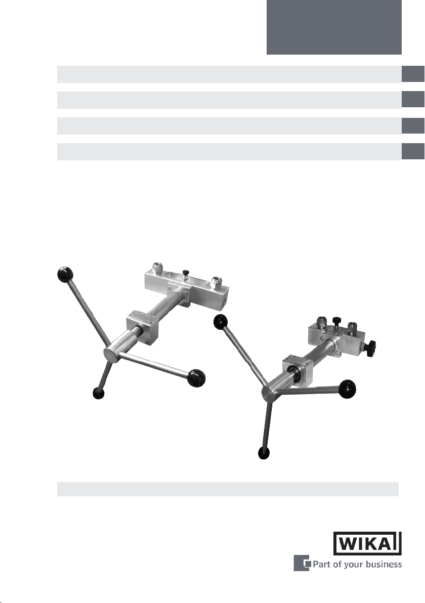
Hand Spindle Pump
Handspindelpumpe
Pompe hydraulique
Bomba manual de husillo
CPP1000-M
CPP1000-L
GB
D
F
E
Hand Spindle Pumps
Page 2

GB
Operating Instructions Hand Spindle Pump Page 3 - 22
D
Betriebsanleitung Handspindelpumpe Seite 23 - 42
F
Mode d‘emploi Pompe hydraulique Page 53 - 62
Manual de instrucciones de la Bomba manual
E
de husillo
Página 63 - 82
11178035 12/2010 GB/D/F/E
2
Page 3

Hand Spindle Pump
CPP1000-M/-L
Contents
1. General 4
1.1 General safety instructions 4
2. Product description 6
2.1 General product information 6
2.2 Arrangement of control elements 6
3. Commissioning and operation 7
3.1 Preparation 7
3.1.1 Setting up the device 7
3.1.2 Filling in of operating liquid 7
3.1.3 Connecting the pressure measuring instruments (reference and test
specimen)
3.1.4 Venting the system 9
3.2 Operation 10
3.3 Handling the CPP1000-M/-L with shut-o valve for test connection 11
3.4 Disassembly 13
4. Troubleshooting measures 13
5. Maintenance and care 15
5.1 Wear parts 15
5.2 Changing the operating liquid 15
6. Mounting instruction for shut-o valve for test connection and
ne adjustment valve
7. Specications 19
8. Dimensions 20
9. Order data / Accessories 21
10. Addresses 83
16
GB
8
Information
This symbol provides you with information, notes and tips.
Warning!
This Symbol warns you against actions that can cause injury
to people or damage to the instrument.
11178035 12/2010 GB/D/F/E
WIKA Operating Instructions Hand Spindle Pump
3
Page 4

Hand Spindle Pump
CPP1000-M/-L
1. General
GB
In the following chapters detailed information on the hand spindle pump CPP1000-M/-L
and its proper use can be found.
Should you require further information, or should there be problems which are not
dealt within detail in the operating instructions, please contact the address listed on
the last page.
The warranty period for the hand spindle pump CPP1000-M/-L is 24 months according
to the general terms of supply of ZVEI.
The warranty is void if the appliance is put to improper use or if the operating instructions are not observed or if an attempt is made to open the appliance or to release
attachment parts or threaded connections.
We also point out that the content of these operating instructions neither forms part
of an earlier or existing agreement, assurance or legal relationship nor is meant to
change these. All obligations of WIKA Alexander Wiegand SE & Co. KG result from the
respective sales contract and the general business terms of WIKA Alexander Wiegand
SE & Co. KG.
WIKA is a registered trade mark of WIKA Alexander Wiegand SE & Co. KG. Names of
companies or products mentioned in this handbook are registered trade marks of the
manufacturer.
We reserve the right to eect reasonable changes on the basis of technical improvements.
Any reproduction of this manual or parts thereof by any means is prohibited.
© 2006 Copyright WIKA Alexander Wiegand SE & Co. KG
1.1 General safety instructions
Read these operating instructions carefully prior to operating
the hand spindle pump CPP1000-M/-L. Its trouble-free operation and reliability cannot be guaranteed unless the safety
advice given in this manual is followed when using the device.
1. The hand spindle pump CPP1000-M/-L must only be operated by trained and
authorised personnel who know the manual and can work according to them.
WIKA Operating Instructions Hand Spindle Pump4
11178035 12/2010 GB/D/F/E
Page 5

Hand Spindle Pump
CPP1000-M/-L
2. Trouble-free operation and reliability of the device can only be guaranteed so long
as the conditions stated under „Setting up the device“ are taken into consideration.
3. The hand spindle pump CPP1000-M/-L always has to be handled with the care
required for a precision instrument (protect from humidity, impacts and extreme
temperatures). The pump must be handled with care (don‘t throw, hit, etc.) and
protect them from contamination. By no means apply any force to the operating
elements (star handle, shut-o valve, test connections) of the hand spindle pump
CPP1000-M/-L.
4. If the device is moved from a cold to a warm environment, you should therefore
ensure the device temperature has adjusted to the ambient temperature before trying
to put it into operation.
5. If the equipment is damaged and might no longer operate safely, then it should be
taken out of use and securely marked in such a way that it is not used again.
Operator safety may be at risk if:
■
There is visible damage to the device.
■
The device is not working as specied.
■
The device has been stored under unsuitable conditions for an extended period of
time.
If there is any doubt, please return the device to the manufacturer for repair or maintenance.
6. Customers must not attempt to alter or repair the device themselves. If the instrument is opened or attachment parts or the threaded connections are released, its
trouble-free operation and reliability is impaired and endangers the operator. Please
return the device to the manufacturer for any repair or maintenance.
7. Use original seals only in the device.
8. Any operation not included in the following instructions or outside the specications
must not be attempted.
GB
11178035 12/2010 GB/D/F/E
WIKA Operating Instructions Hand Spindle Pump
5
Page 6
Hand Spindle Pump
CPP1000-M/-L
2. Product description
GB
2.1 General product information
■
Application
Hand spindle pumps are used to generate pressures for checking, adjusting and
calibrating mechanical and electronic pressure measuring instruments by comparative measurements. These pressure tests may be carried out in laboratories,
workshops or on site at the measuring point.
■
Functionality
If the instrument to be tested and a suciently accurate reference measuring instrument are connected up to the test pump, the same pressure is applied to the two
measuring instruments when the hand spindle pump is operated. By comparing the
two measured values at random pressure values, the accuracy can be veried or
the instrument under test can be adjusted. The hand spindle pump is equipped with
a precision spindle to make it possible to approach measuring points exactly. The
CPP1000-M/-L is particularly notable for the rotating spindle that only runs inside
the body of the pump. This eliminates the negative eect of a bending torque on a
spindle turning outside the body and oers the advantage, especially for use in the
eld, that the dimensions of these hand spindle pumps do not change during opera-
tion due to the spindle turning.
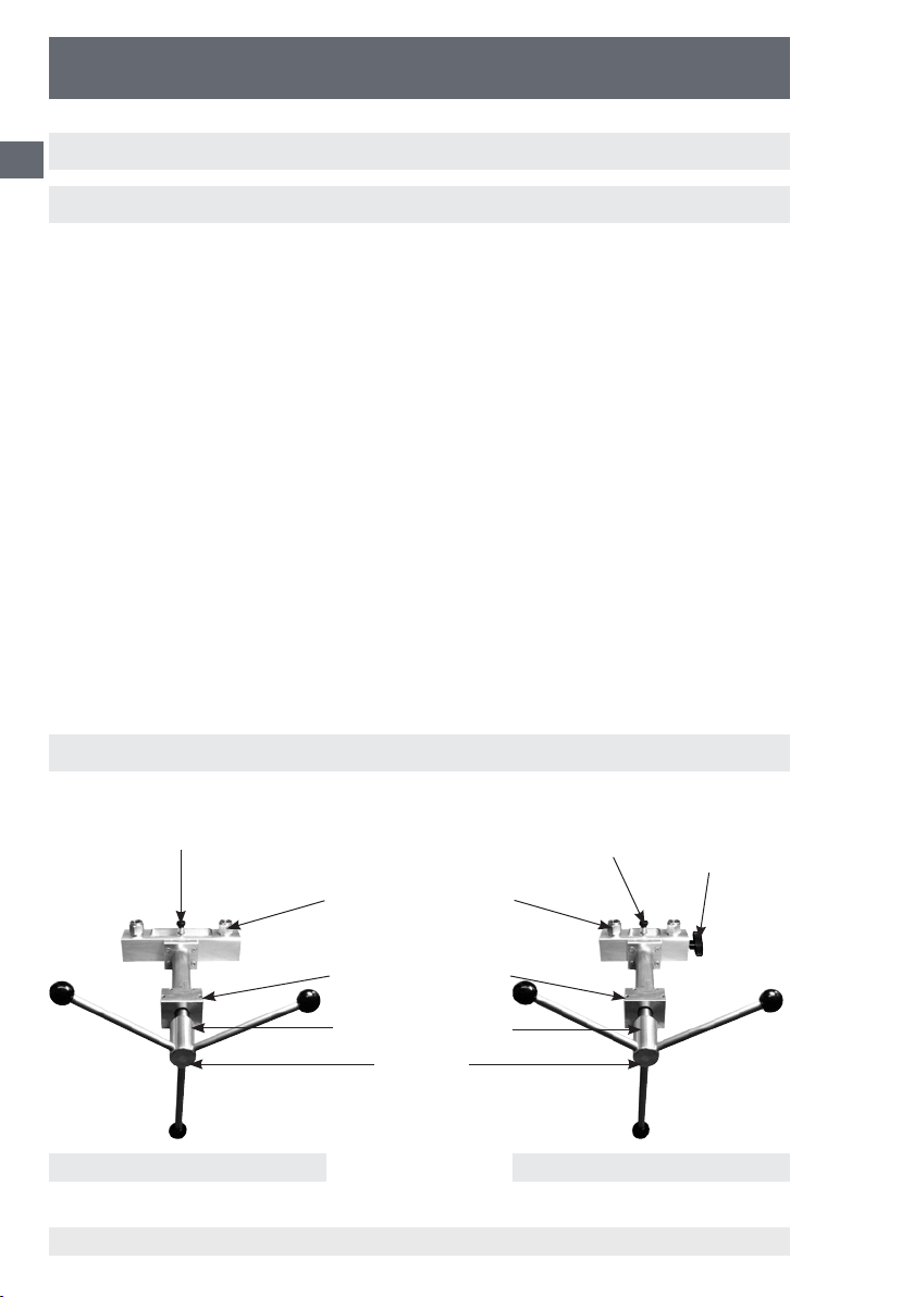
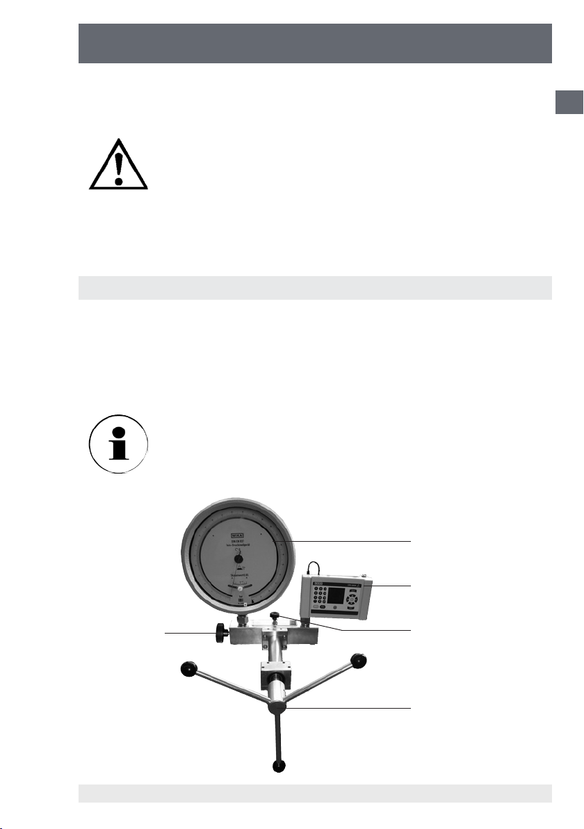
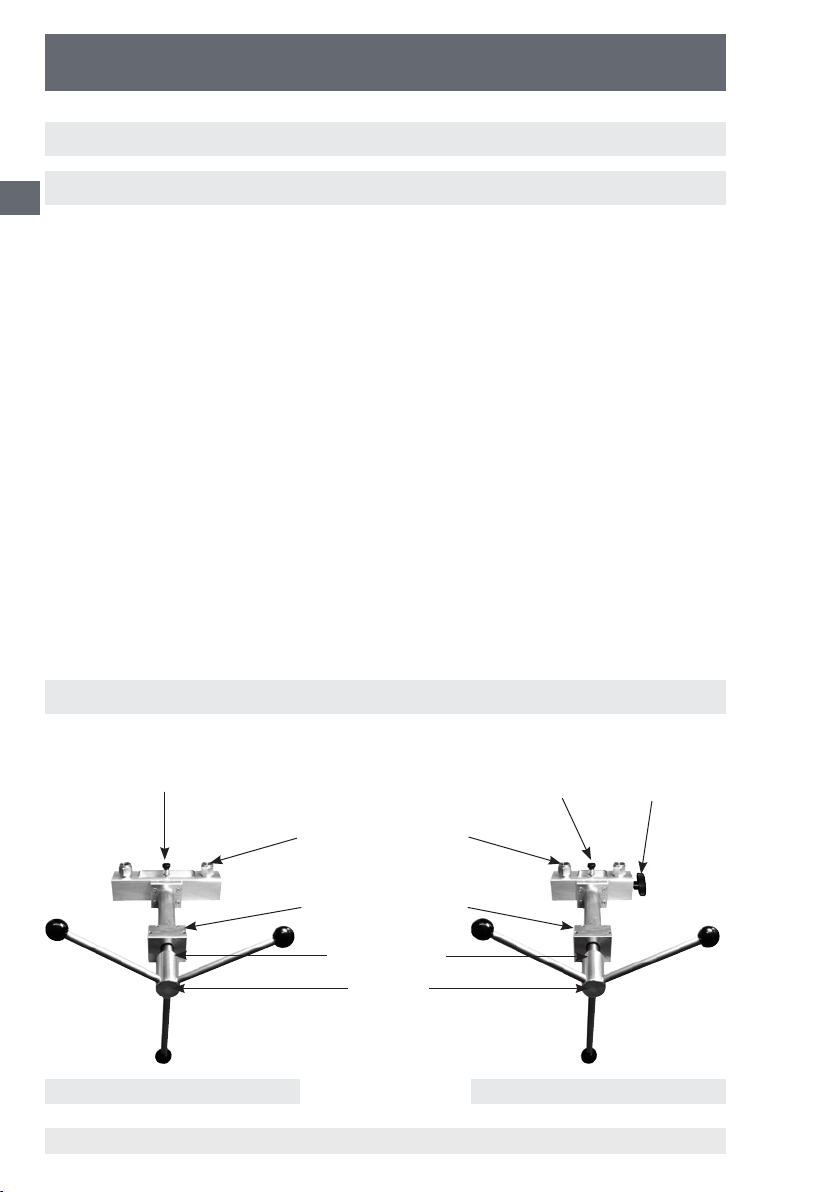
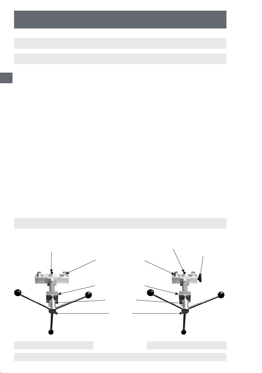
2.2 Arrangement of control elements
Reservoir and shut-o valve Fine adjust-
2 Pressure connections for
gauges G½ (reference and
test specimen)
2 Through holes 6.4 mm for
stationary fastening
Spring-loaded thrust pad
Star handle
Reservoir (sealed) and
shut-o valve
CPP1000-M CPP1000-L
WIKA Operating Instructions Hand Spindle Pump6
ment valve
11178035 12/2010 GB/D/F/E
Page 7

Hand Spindle Pump
CPP1000-M/-L
3. Commissioning and operation
3.1 Preparation
3.1.1 Setting up the device
■
Set up the hand spindle pump on a solid surface.
Avoid unsafe mounting conditions. If necessary, it can be secured by mounting on
a baseplate or workbench using appropriate screws. Two drillings (Ø 6.4 mm) are
available on the front ange for this purpose.
■
Place the star handle with knobs onto the spindle pump.
Ensure that the spring-loaded thrust pad engages into the star handle bushing.
3.1.2 Filling in of operating liquid (rst commissioning)
As an operating liquid only the following are suitable for the
CPP1000-M/-L:
■
Mineral oil based hydraulic uid
■
Clean water, free of calcium-carbonate / scale
Distilled water and water-based hydraulic uids are not
suitable!
Other pressure transmitting media are available on request.
GB
Fill the hand spindle pump with a suitable operating liquid as follows:
■
Turn the spindle completely clockwise.
■
Open the shut-o valve and unscrew it completely, then remove the top cover of the
reservoir.
■
Pour the operating liquid carefully and slowly, alternating between both pressure
connections. You can monitor how the operating liquid settles into the reservoir.
Pour the liquid into the pressure connections until the reservoir is ½ to ¾ full.
■
Place the top cover of the reservoir back on and reattach the shut-o valve.
11178035 12/2010 GB/D/F/E
WIKA Operating Instructions Hand Spindle Pump
7
Page 8
Hand Spindle Pump
CPP1000-M/-L
3.1.3 Connecting the pressure measuring instruments (reference and test
GB
specimen)
■
The pressure connections have G ½ female threads.
When you are calibrating devices with dierent connection threads,
please use appropriate threaded adapters (see chapter 9. Accessories).
■
Before connecting the reference pressure instrument and test item, the system
should be vented. For this, oil is pumped into the system by opening the pressure
connections by carefully turning the star handle in a clockwise direction. It should be
turned until oil appears at the o-ring seals of the open pressure connection and no
more air bubbles are escaping. The shut-o valve on the reservoir must be closed
and any shut-o valves for the test conection installed must be opened.
■
Connect the reference pressure measuring instrument and the instrument to be
inspected (test specimen), one to each of the CPP1000-M/-L two pressure connections. The pressure connections are free-rotating, so that you can align the instruments in such a way that a proper reading is ensured. An O-ring seal is already
tted, so no additional sealing material is required. Hand tightening is sucient to
make a proper seal.
■
To calibrate instruments with back mounting connection there is an angle connection 90° available (see chapter 9. Accessories).
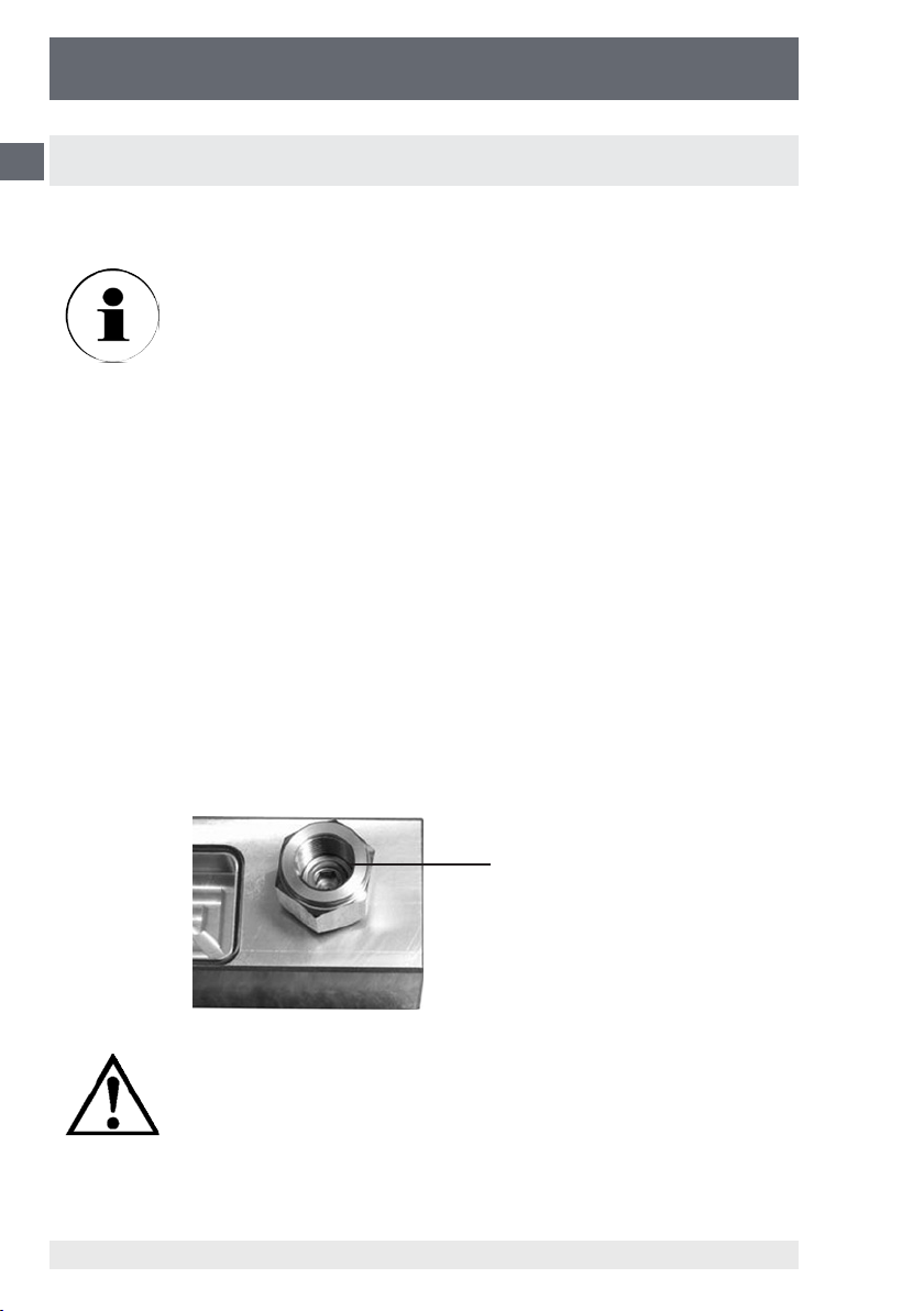
O-ring seal
Check the O-ring seal in the pressure connections for proper
seat and for any wear. Replace, if necessary (See chapter 9.
Accessories). Please see to it that each instrument mounted
to the test pump must be clean inside.
WIKA Operating Instructions Hand Spindle Pump8
11178035 12/2010 GB/D/F/E
Page 9
Hand Spindle Pump
CPP1000-M/-L
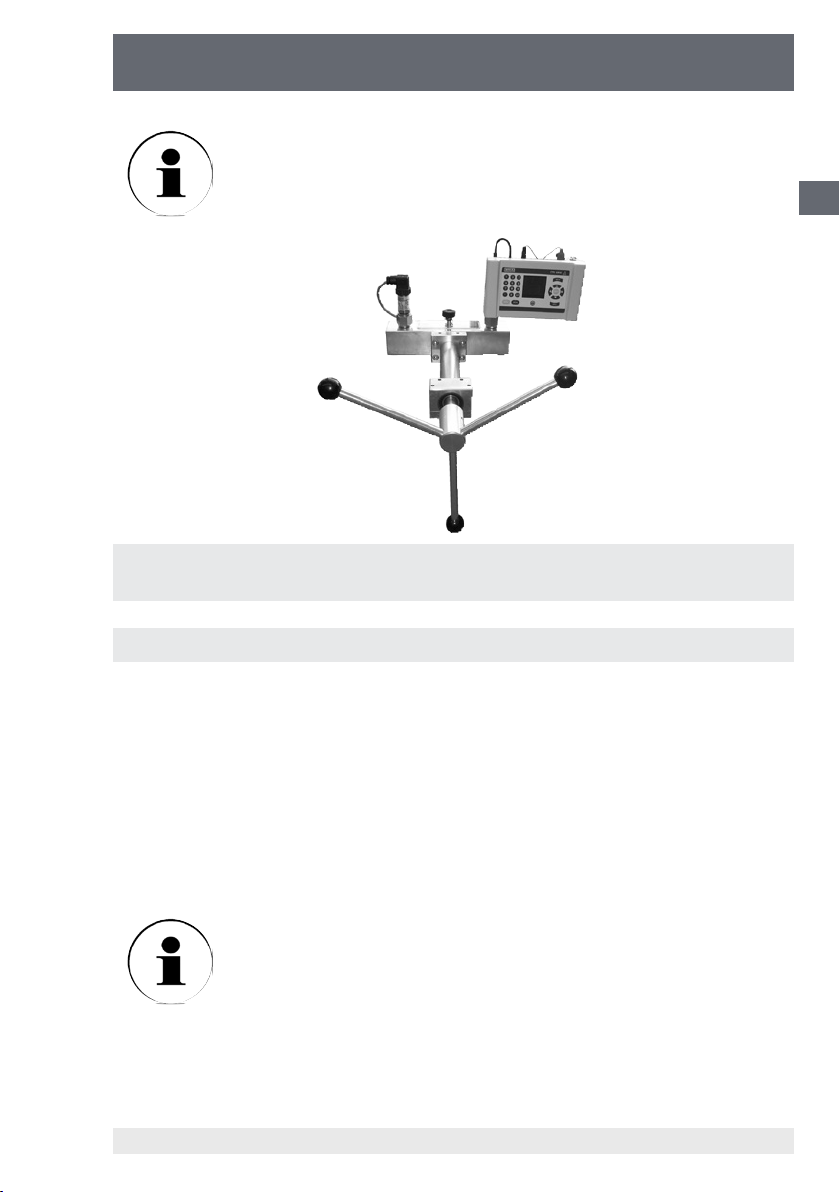
For calibration cycles with larger volumes, it is advisable to ll the
test specimen/reference with the operating liquid beforehand or to
use the shut-o valve for test connection, which is available as an
accessory (see chapter 9. Accessories).
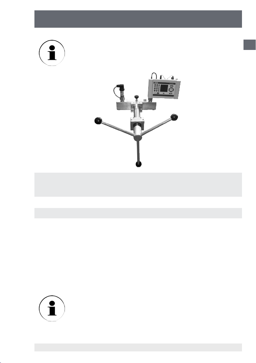
Example: A calibration assembly with the CPP1000-M/-L and a CPH6000
process calibrator as the reference instrument and a pressure transmitter as
the test specimen
3.1.4 Venting the system
GB
After the measuring instrument has been mounted, further trapped air can be found
in the system. The system can be vented before the start of the calibration using the
following procedure:
■
Open the shut-o valve on the reservoir.
■
Turn the star handle anticlockwise until fully out/open.
■
Close the valve.
1) Turn the star handle clockwise until the test specimen and/or the reference
indicates a pressure of approx. 50 to 100 bar.
If, after the spindle has been fully wound in in a clockwise direction,
there is no increase in pressure, then the connected test volume
is too large, and the instruments will need pre-lling with operating
liquid before being attached to the pump or the shut-o valve for test
connection, which is available as an accessory, is to be used (see
11178035 12/2010 GB/D/F/E
WIKA Operating Instructions Hand Spindle Pump
chapter 9. Accessories).
9
Page 10
Hand Spindle Pump
CPP1000-M/-L
2) Fully open the valve, slowly and carefully. You will notice any escaping air bubbles.
GB
3) Close the valve again.
4) Turn the star handle further in a clockwise direction, until the test specimen and/or
the reference again indicates a pressure value of approx. 50 to 100 bar.
5) Fully open the valve, slowly and carefully. If necessary, check again if any air
bubbles escape.
6) Close the valve again.
7) Turn the star handle anticlockwise all the way out.
8) Open the valve.
9) After approximately 10 seconds, close the valve.
■
Repeat steps 1) to 9) again, if necessary.
The CPP1000-M/-L hand spindle pump is now ready to use.
For test specimens or reference instruments with particularly large
volumes we recommend lling them with operating liquid beforehand
or using the shut-o valve for test connection, which is available as
an accessory (see chapter 9. Accessories).
3.2 Operation
The maximum permissible pressure for the CPP1000-M/-L is
1000 bar. Higher pressures may damage the pump. The refer-
ence instrument, test specimen and any connecting tubes
that are used must not be subjected to pressures above the
maximum permissible level.
■
We recommend unscrewing the spindle completely when you start to record
measurement values, (turning anticlockwise) to allow enough volume for measurements.
■
To increase the test pressure turn the star handle clockwise.
■
To decrease the test pressure turn the star handle anticlockwise.
■
The use of a ne adjustment valve (CPP1000-L availabel as standard) allows to
make ne adjustments to the initial pressure setting by turning the ne adjustment
valve in or out.
■
The display of the instrument under test can be compared with the reference
measuring instrument at each individual calibration point.
Since small amounts of air are always compressed in the system
together with the medium, the test pressure that has been generated
rst drops o slightly. After this it must be readjusted.
WIKA Operating Instructions Hand Spindle Pump10
11178035 12/2010 GB/D/F/E
Page 11
Hand Spindle Pump
CPP1000-M/-L
At higher pressures a longer waiting time before stable operating conditions are
reached is to be expected than at lower pressures.
NEVER open the shut-o valve suddenly while the system is
pressurised. The valve may be opened only if the spindle has
been fully unscrewed in an anticlockwise direction.
(Exception: chapter 3.1.4 Venting the system)
■
Turn the spindle pump anticlockwise as far as the end-stop to vent the system
completely and only then open the shut-o valve.
■
You can now change the test specimen (and/or the reference instrument).
3.3 Handling the CPP1000-M/-L with shut-o valve for test connection
When calibrating instruments with large volume a shut-o valve for the test connections is a useful accessory (see chapter 9. Accessories). This shut-o valve makes
it possible to draw pressure medium from the reservoir into the pump and into the
connected test gauges. So it is not necessary to ll pressure medium into the test
specimen or the reference instrument before connecting to the pump.
For devices under test and reference instruments with a large
volume we recommend a shut-o valve on each test connection. When a ne adjustment valve (available as standard with
CPP1000-L) is used, only one shut-o valve can be mounted for the
test connection.
GB
3
11178035 12/2010 GB/D/F/E
WIKA Operating Instructions Hand Spindle Pump
4
5
2
1
(1) Star handle
(2) Shut-o valve for reservoir
(3) Shut-o valve for test connections
(4) Test specimen
(5) Reference instrument
11
Page 12

Hand Spindle Pump
CPP1000-M/-L
Mounting and preparation/Venting the system
GB
■
Mount the shut-o valve (3) in the surface mounting ange at the side of the pump
in exchange for the screw plug mounted as standard. During this process the pump
must be free of pressure (see chapter 6. Mounting instruction).
■
Mount the test specimen (4) on the test connection.
■
Mount the reference instrument (5) on the second test connection.
■
Put the reservoir cap back on and t the shut-o valve (2). However, leave the valve
open!
■
Close the shut-o valve(s) for test connections (3) by turning them clockwise.
■
Turn the star handle anticlockwise until fully out/open.
1) Close the shut-o valve on the reservoir (2).
2) Open the shut-o valve(s) for test connections (3) by turning them counterclockwise
(less than one complete turn is su-cient).
3) Turn the star handle (1) clockwise until the test specimen and/or the reference
indicates a pressure of appro. 50 to 100 bar.
4) Fully open the valve (2), slowly and carefully. If necessary, check again if any air
bubbles escape.
5) Close the shut-o valve on the reservoir (2).
6) Close the shut-o valve(s) for test connections (3) by turning them clockwise.
7) Turn the star handle anticlockwise all the way out.
■
Repeat steps 1) to 7) several times.
Operation
■
Open the shut-o valve (3) on the test specimen and close the shut-o valve on the
reservoir (2).
■
Turn the star handle clockwise. Operating liquid is pressed into the connected test
specimen.
■
If the connected instrument has still not been lled enough or if the required pressure has still not been reached, close the shut-o valve on the test specimen (3).
■
Open the shut-o valve on the reservoir (2) and turn the star handle counterclock-
wise as far as it will go. New pressure medium is drawn from the reservoir into the
cylinder of the pump.
■
Close shut-o valve on the reservoir (2).
■
Open shut-o valve on the test specimen (3).
■
Turn the star handle clockwise again.
■
Repeat the process described here until the required pressure is reached.
WIKA Operating Instructions Hand Spindle Pump12
11178035 12/2010 GB/D/F/E
Page 13
Hand Spindle Pump
CPP1000-M/-L
3.4 Disassembly
■
After all pressure points have been recorded (at the end of the test specimen
calibration), fully unscrew the spindle and open the valve.
■
Now you can disconnect the test specimen (and if necessary the reference instrument) from its pressure connection.
Disconnect the test specimen and/or the reference instrument
only after the pressure within the hand spindle pump has
been completely relieved.
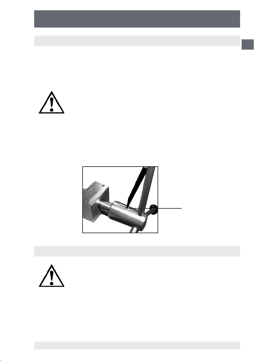
■
In order to remove the star handle from the spindle pump, the spring-loaded thrust
pad must be pressed downward with the aid of a small screwdriver, or a ball-point
pen. The star handle may now be pulled o toward the front.
■
When transporting the hand spindle pump it is recommended to empty the pump
fully. The test connections should be sealed with plugs (see chapter 9. Accessories).
Spring-loaded
thrust pad
GB
4. Troubleshooting measures
If faults cannot be eliminated will the aid of the operating
istructions, the system must be put out of operation immedi-
ateley and the manufacturer i to be informed.
Repairs must only be carried out by the manufacturer. Intern-
ventions and changes on the appliance are not allowed.
In case of faults caused by defects of the hydraulic equipment the operators must
inform their superiors immediately and call in the qualied and authorised technical
sta for maintenance.
11178035 12/2010 GB/D/F/E
WIKA Operating Instructions Hand Spindle Pump
13
Page 14

Hand Spindle Pump
CPP1000-M/-L
Table: Fault description and measures
GB
Type of fault: Measures:
I. Unable to build up pressure/leak in
the system
II. Unable to build up pressure, or
maximum pressure cannot be
reached
III. Slow pressure drop
■
Close shut-o valve of the reservoir
correctly
■
Check whether the seals have been
placed in the pressure connections and
whether they are properly positioned.
■
After the mounting of the test specimen
and the reference instrument, air may be
trapped in the system.
Please note: The system should be vented
before beginning with calibration. For this
purpose, proceed according to chapters
3.1.2 to 3.1.4.
■
Afterwards, build the pressure back up.
NOTE: For calibration cycles with larger
volumes, it is advisable to ll the test specimen, and if necessary, the reference instrument with operating liquid beforehand or to
use the shut-o valve for test connection,
which is available as an accessory (see
chapter 9. Accessories).
■
Leak in the system, see point I.
■
If small amounts of air are always
compressed in the system together with
the medium, the test pressure that has
been generated rst drops o slightly.
After this it must be readjusted.
■
If the system is pressurised quickly, it
takes a certain time (<1 minute) until it can
stabilise thermally. The pressure should
then be adjusted accordingly.
■
After the clamping of the test specimen
and the reference instrument, air may be
trapped in the system, see point II.
■
Afterwards, build the pressure back up.
Further help can be found through WIKA‘s Test & Calibration Technolgy Department.
WIKA Operating Instructions Hand Spindle Pump14
11178035 12/2010 GB/D/F/E
Page 15

Hand Spindle Pump
CPP1000-M/-L
5. Maintenance and care
The hand spindle pump can be easily cleaned by wiping down with a damp cloth.
No maintenance tasks should be undertaken on the spindle pump. With any clearly
visible signs of wear, it must be sent back to the manufacturer for refurbishment (after
cost estimate).
5.1 Wear parts
The O-rings in the pressure connections are subjected to wear. Both O-rings must be
checked for proper seat and any wear before any calibrating is performed. If necessary, the O-rings must be replaced at regular intervals, or whenever necessary (see
chapter 9. Accessories).
Use original seals only. Seals having deviant measurements,
or materials, or material grades, may cause damage to the
device and test specimen or to the reference instrument, and
pose a danger for the operator.
5.2 Changing the operating liquid
The hydraulic oil should be changed whenever visible contamination is present.
GB
Removing the operating liquid
■
Open the shut-o valve, by unscrewing it completely.
■
Take the transparent lid o.
■
Draw the liquid out of the reservoir e.g. with a suitable syringe.
■
In addition, any small residual quantities of oil can be drawn o at the pressure
connections, by slowly turning the spindle pump, with the shut-o valve closed.
■
Minute amounts of oil residue may remain in the piping
Waste oil must be disposed of according to legal requirements.
■
To rell and vent the system follow the instructions already given in chapter 3.1.2 to
3.1.4.
11178035 12/2010 GB/D/F/E
WIKA Operating Instructions Hand Spindle Pump
15
Page 16
Hand Spindle Pump
CPP1000-M/-L
6. Mounting instruction for shut-o valve for test connec-
GB
tion and ne adjustment valve
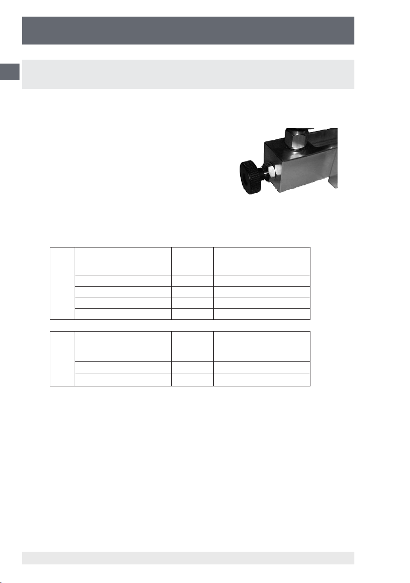
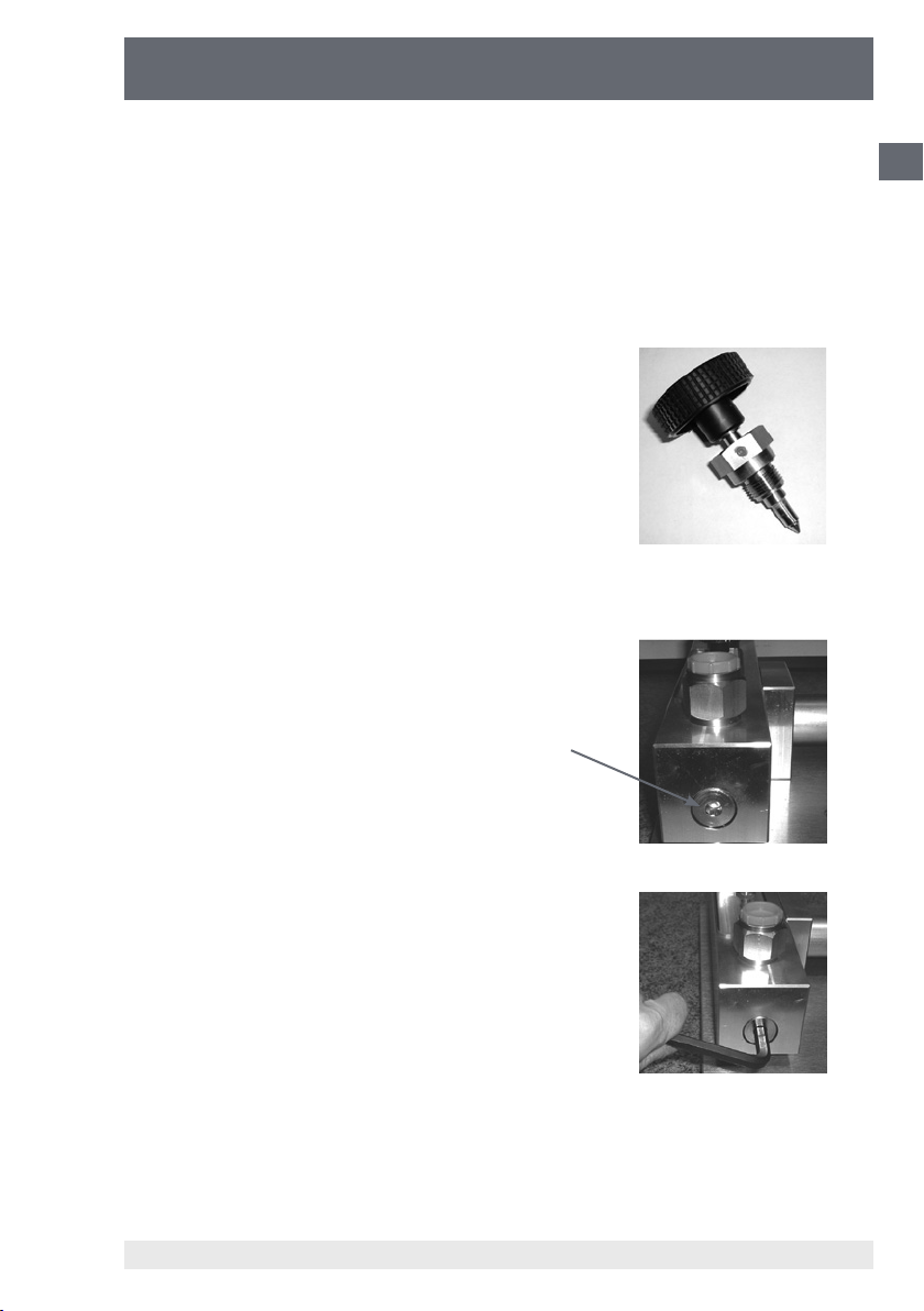
The mounting instruction describes the subse-
quent mounting of the shut-o valve for test
connection (Order No. 11208384) or of the ne
adjustment valve (Order No. 11248351). The
valves can be mounted at the side of the back
ange in exchange for the blind plugs which are
installed as standard.
The following combinations are possible for the individual pump versions.
Shut-o valve for test
connection
1 with 0
0 with 1
CPP1000-M
Shut-o valve for test
CPP1000-L
If only one instrument (reference gauge or test item) with large volume is mounted on
the CPP1000-M, only one shut-o valve for test connection is needed. If both gauges
(reference and test item) have large volumes, the usage of two shut-o valves is
recommended.
When 2 shut-o valves are used, it is not possible to mount a ne adjustment valve.
1 with 1
2 with 0
connection
1 with installed as standard
0 with installed as standard
Fine adjustment valve
Fine adjustment valve
11178035 12/2010 GB/D/F/E
WIKA Operating Instructions Hand Spindle Pump16
Page 17
Hand Spindle Pump
CPP1000-M/-L
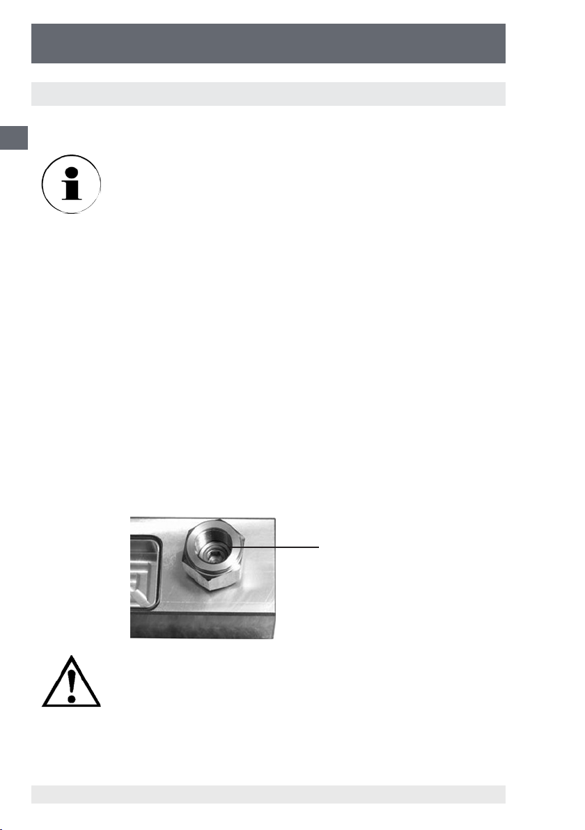
For mounting you need the following tools:
■
Allen wrench 8 mm
■
Flat wrench SW 27
■
Tweezers
■
1 piece valve with integrated seals
Side view of hand spindle pump showing the blind plug with hexagon socket
blind plug with
hexagon socket
GB
Open the blind plug using an 8 mm allen wrench
and dismount the blind plug completely.
11178035 12/2010 GB/D/F/E
WIKA Operating Instructions Hand Spindle Pump
17
Page 18
Hand Spindle Pump
CPP1000-M/-L
GB
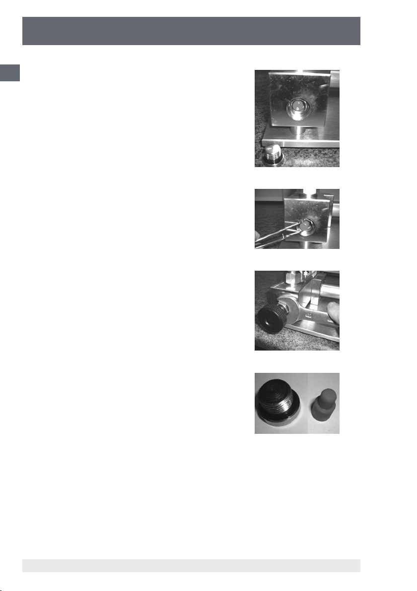
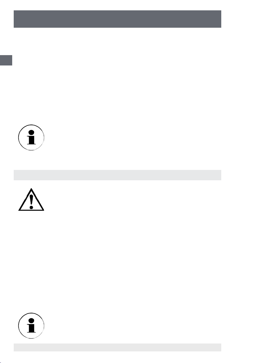
If the blind plug is removed completely, a small
cylindrical body, made of red plastic, is visible.
This plastic body is to reduce the internal volume
of the pump if a shut-o valve or ne adjustment
valve is not used / mounted.
Remove the red cylindrical body using tweezers
or blow it out through the open test connection
using compressed air.
Now screw in the shut-o valve or the ne adjustment valve.
Pull tight the valve using a at wrench 27 mm.
This parts are left over and may be depolluted:
■
blind plug
■
red cylindrical body
WIKA Operating Instructions Hand Spindle Pump18
11178035 12/2010 GB/D/F/E
Page 19

Hand Spindle Pump
CPP1000-M/-L
7. Specications
CPP1000-M CPP1000-L
Pressure range bar 0 ... 1000
Medium
Pressure connections 2 x G ½“ female thread, rotating, with o-ring
Distance of the test connections mm 200 115
Liquid container cm³ 110 55
Piston diameter mm 8
Swept volume per revolution cm³ approx. 0.1
Overall swept volume cm³ approx. 3.9
Pressure ne adjustment option, see accessories
Required moment at
- 250 bar Nm 2.0
- 500 bar Nm 4.0
- 1000 bar Nm 8.0
Material
- Piston Stainless steel
- Cylinder Brass
- Rear ange Aluminium
- Sealing gaskets FKM and NBR; optional EPDM
Stationary fastening two through holes in the front ange Ø 6.4 mm
Dimensions mm 420 (L) x 280 (W) x 103 (H) 420 (L) x 240 (W) x 103 (H)
Weight kg 6.3 5,6
Mineral oil based hydraulic uid / clean water, free of
calcium-carbonate / scale
1)
lateral ne adjustment
valve
GB
1) Other pressure transmitting media on request.
11178035 12/2010 GB/D/F/E
WIKA Operating Instructions Hand Spindle Pump
19
Page 20
Hand Spindle Pump
CPP1000-M/-L
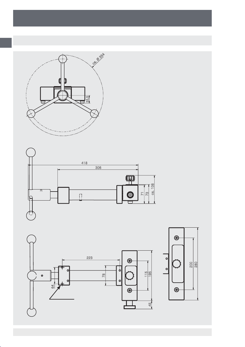
8. Dimensions
GB
ca. Ø 354
33,5
418
306
64
2 x Ø 6.4
223
ca. 108
71
73
280
200
195
78
115
45
CPP1000-MCPP1000-L
11178035 12/2010 GB/D/F/E
WIKA Operating Instructions Hand Spindle Pump20
Page 21

Hand Spindle Pump
CPP1000-M/-L
9. Order data / Accessories
Accessories Order No.
Hand spindle pump CPP1000-M/-L 12401447
Hand spindle pump CPP1000-L, portable version incl. ne adjust-
ment valve and sealed tank cap
Operating liquid for CPP1000 and CPP1600 test pump series in
plastic bottle, content 1 litre
Shut-o valve for test connection for an easy lling of instruments
with a large volume with pressure transmitting medium directly on
the hand spindle pump.
Max. permissible pressure: 1000 bar
For devices under test and reference instruments with a large
volume we recommend 2 shut-o valves.
Fine adjustment valve for subsequent mounting into Model
CPP1000-M; enables the exact setting up of pressure values
Blind plug G ½ male thread, material: brass 11155230
Set of O-rings consisting of 10 spare sealings for pressure ports,
material: FKM/FPM
Threaded adapter G ½ male thread on G ⅛ female thread, materi-
al: brass
Threaded adapter G ½ male thread on G ¼ female thread, materi-
al: brass
Threaded adapter G ½ male thread on G ⅜ female thread,
material: brass
Threaded adapter G ½ male thread on M20 x 1.5 female thread,
material: brass
Threaded adapter G ½ male thread on ¼ NPT female thread,
material: brass
Threaded adapter G ½ male thread on ½ NPT female thread,
material: brass
Angle connection 90° for test specimens with back mounting
connection
12677133
2099882
11208384
11248351
12422487
9090207
9090231
9090266
9090355
0187119
0187143
1564838
GB
11178035 12/2010 GB/D/F/E
WIKA Operating Instructions Hand Spindle Pump
21
Page 22

Hand Spindle Pump
CPP1000-M/-L
GB
11178035 12/2010 GB/D/F/E
WIKA Operating Instructions Hand Spindle Pump22
Page 23
Handspindelpumpe
CPP1000-M/-L
Inhalt
1. Allgemeines 24
1.1 Allgemeine Sicherheitshinweise 24
2. Produktbeschreibung 26
2.1 Allgemeine Produktinformationen 26
2.2 Anordnung der Bedienelemente 26
3. Inbetriebnahme und Betrieb 27
3.1 Vorbereitung 27
3.1.1 Aufstellung des Gerätes 27
3.1.2 Befüllen des Systems mit Betriebsüssigkeit 27
3.1.3 Anschluss der Druckmessgeräte (Referenz und Prüing) 28
3.1.4 Entlüften des Systems 29
3.2 Betrieb 30
3.3 Handhabung der CPP1000-M/-L mit Prüfanschluss/Absperrventil 31
3.4 Abbau 33
4. Maßnahmen bei Störungen 33
5. Pege und Wartung 35
5.1 Verschleißteile 35
5.2 Austausch der Betriebsüssigkeit 35
6. Einbauanleitung für Absperrventil für Prüfanschluss und Feinregulierventil
7. Technische Daten 39
8. Abmessungen 40
9. Bestelldaten / Zubehör 41
10. Adressen 83
36
D
Information
Dieses Zeichen gibt Ihnen Informationen, Hinweise oder Tipps.
Warnung!
Dieses Symbol warnt Sie vor Handlungen, die Schäden an
Personen oder am Gerät verursachen können.
11178035 12/2010 GB/D/F/E
WIKA Betriebsanleitung Handspindelpumpe 23
Page 24

Handspindelpumpe
CPP1000-M/-L
1. Allgemeines
In den folgenden Kapiteln erhalten Sie nähere Informationen zur Handspindelpumpe
D
CPP1000-M/-L und ihren ordnungsgemäßen Einsatz. Sollten Sie weitere Informationen wünschen, oder treten besondere Probleme auf, die in der Betriebsanleitung nicht
ausführlich behandelt werden, erhalten Sie Auskunft unter den auf der letzten Seite
aufgelisteten Adressen.
Die Gewährleistungszeit für die Handspindelpumpe CPP1000-M/-L beträgt 24 Monate
nach den Allgemeinen Lieferbedingungen des ZVEI. Sämtliche Gewährleistungsansprüche verfallen, bei unsachgemäßer Handhabung bzw. bei Nichtbeachtung der
Betriebsanleitungen oder bei dem Versuch das Gerät zu önen bzw. Anbauteile oder
Verschraubungen zu lösen.
Außerdem weisen wir darauf hin, dass der Inhalt dieser Betriebsanleitung nicht Teil
einer früheren oder bestehenden Vereinbarung, Zusage oder Rechtsverhältnisses ist
oder diese abändern soll.
Sämtliche Verpichtungen der WIKA Alexander Wiegand SE & Co. KG ergeben sich
aus dem jeweiligen Kaufvertrag und den Allgemeinen Geschäftsbedingungen der
WIKA Alexander Wiegand SE & Co. KG.
WIKA ist ein eingetragenes Warenzeichen der WIKA Alexander Wiegand SE & Co.
KG.
Firmen- oder Produktnamen, die in diesem Handbuch erwähnt werden, sind eingetragene Warenzeichen dieser Hersteller.
Zumutbare Änderungen aufgrund technischer Verbesserungen behalten wir uns vor.
Eine Vervielfältigung dieses Handbuches oder Teilen davon ist untersagt.
© 2006 Copyright WIKA Alexander Wiegand SE & Co. KG
1.1 Allgemeine Sicherheitshinweise
Lesen Sie diese Bedienungsanleitung sorgfältig, bevor Sie die
Handspindelpumpe CPP1000-M/-L einsetzen. Die Funktion und
Betriebssicherheit des Gerätes kann nur dann gewährleistet
werden, wenn die Sicherheitshinweise der Bedienungsanleitung beachtet werden.
WIKA Betriebsanleitung Handspindelpumpe24
11178035 12/2010 GB/D/F/E
Page 25

Handspindelpumpe
CPP1000-M/-L
1. Die Handspindelpumpe CPP1000-M/-L darf nur von dafür ausgebildeten und
befugten Personen bedient werden, die die Bedienungsanleitung kennen und
danach arbeiten können!
2. Die einwandfreie Funktion und Betriebssicherheit der Handspindelpumpe
CPP1000-M/-L kann nur unter Berücksichtigung der im Kapitel “Aufstellung des
Gerätes” beschriebenen Bedingungen eingehalten werden.
3. Die Handspindelpumpe CPP1000-M/-L ist stets mit der für ein Präzisionsgerät
erforderlichen Sorgfalt zu behandeln (vor Nässe, Stößen und extremen Tempe-
raturen schützen). Die Pumpe muss peglich behandelt werden (nicht werfen,
aufschlagen, usw.) und ist vor Verschmutzung zu schützen. Vermeiden Sie
unbedingt jegliche Gewalteinwirkung auf die Bedienungselemente (Spindelrad,
Ventil, Prüingsanschlüsse) der Handspindelpumpe CPP1000-M/-L.
4. Wird das Gerät von einer kalten in eine warme Umgebung transportiert, muss die
Angleichung der Gerätetemperatur an die Raumtemperatur vor einer erneuten
Inbetriebnahme abgewartet werden.
5. Wenn anzunehmen ist, dass das Gerät nicht mehr gefahrlos betrieben werden
kann, so ist es außer Betrieb zu setzen und vor einer Wiederinbetriebnahme durch
Kennzeichnung zu sichern.
Die Sicherheit des Benutzers kann durch das Gerät beeinträchtigt sein, wenn
es zum Beispiel:
D
■
Sichtbare Schäden aufweist
■
Nicht mehr wie vorgeschrieben arbeitet
■
Längere Zeit unter ungeeigneten Bedingungen gelagert wurde
Im Zweifelsfall das Gerät grundsätzlich an den Hersteller zur Reparatur bzw. Wartung
einschicken.
6. Es dürfen am Gerät keine Veränderungen oder Reparaturen vom Kunden vorge-
nommen werden. Das Önen des Gerätes oder das Lösen von Anbauteilen, oder
von Verschraubungen beeinträchtigt die Funktions- und Betriebssicherheit und
stellt eine Gefahr für die Bedienperson dar. Zur Wartung oder Reparatur muss das
Gerät zum Hersteller eingesandt werden.
7. Es dürfen nur Original-Dichtungen im Gerät verwendet werden.
8. Ein anderer Betrieb als der in der folgenden Anleitung beschriebene oder außer-
halb der Spezikation, ist bestimmungswidrig und muss daher ausgeschlossen
werden.
11178035 12/2010 GB/D/F/E
WIKA Betriebsanleitung Handspindelpumpe 25
Page 26
Handspindelpumpe
CPP1000-M/-L
2. Produktbeschreibung
2.1 Allgemeine Produktinformationen
D
■
Einsatz
Handspindelpumpen dienen zur Druckerzeugung für die Überprüfung, Justage
und Kalibrierung von mechanischen und elektronischen Druckmessgeräten durch
Vergleichsmessungen. Diese Druckprüfungen können stationär im Labor oder
Werkstatt, oder vor Ort an der Messstelle stattnden.
■
Funktionsweise
Schließt man das zu prüfende Gerät und ein hinreichend genaues ReferenzDruckmessgerät an der Handspindelpumpe an, so wirkt bei Betätigung der Pumpe
auf beide Messgeräte der gleiche Druck. Durch Vergleich der beiden Messwerte
bei beliebigen Druckwerten kann eine Überprüfung der Genauigkeit bzw. eine
Justage des zu prüfenden Druckmessgerätes erfolgen. Zum exakten Anfahren der
Messpunkte ist die Handspindelpumpe CPP1000-M/-L mit einem fein zu betätigenden Spindelrad ausgestattet. Die CPP1000-M/-L zeichnet sich durch eine innerhalb
des Pumpenkörpers laufende Drehspindel aus. Damit entfällt ein nachteiliges
Biegemoment auf eine herausgedrehte Spindel und speziell für einen Einsatz vor
Ort besteht außerdem der Vorteil, dass sich die Abmessungen der Handspindelpumpe während des Betriebs durch Drehen der Spindel nicht verändern.
2.2 Anordnung der Bedienelemente
Mediumvorratsbehälter und
Absperrventil
2 Druckanschlüsse G½“ für
Messgeräte (Referenz und
2 Bohrungen 6,4 mm für
stationäre Befestigung
Federdruckstück
CPP1000-M CPP1000-L
Prüing)
Drehkreuz
Mediumvorratsbehälter
(abgedichtet) und Absperrventil
WIKA Betriebsanleitung Handspindelpumpe26
Feinregulierventil
11178035 12/2010 GB/D/F/E
Page 27

Handspindelpumpe
CPP1000-M/-L
3. Inbetriebnahme und Betrieb
3.1 Vorbereitung
3.1.1 Aufstellung des Gerätes
■
Stellen Sie die Handspindelpumpe auf eine feste Unterlage. Vermeinden Sie einen
unsicheren Stand. Gegebenenfalls kann eine stationäre Befestigung auf einer
Grundplatte oder Werkbank mit geeigneten Schrauben durchgeführt werden, hierzu
sind zwei Bohrungen (Ø 6,4 mm) am Vorderansch vorhanden.
■
Stecken Sie das Drehkreuz mit den Grien auf die Spindelpumpe auf. Achten Sie
hierbei darauf, dass das Federdruckstück in die Drehkreuzhülse einrastet.
3.1.2 Befüllen des Systems mit Betriebsüssigkeit (Erst-Inbetriebnahme)
Als Betriebsüssigkeit ist für die CPP1000-M/-L ausschließlich
geeignet:
■
Hydrauliküssigkeiten auf Mineralölbasis
■
sauberes kalkfreies Wasser
Nicht geeignet sind destilliertes Wasser und wasserbasierende Hydrauliküssigkeiten!
Andere Druckübertragungsmedien auf Anfrage.
Befüllen Sie die Handspindelpumpe wie folgt mit geeigneter Betriebsüssigkeit:
■
Drehen Sie die Spindel vollständig in Uhrzeigerlaufrichtung ein.
■
Önen Sie das Absperrventil und drehen Sie es vollständig heraus, nehmen Sie
den Vorratsbehälter-Deckel ab.
■
Füllen Sie die Betriebsüssigkeit vorsichtig und langsam abwechselnd in beide
Druckanschlüsse ein.
Sie können dabei beobachten, wie die Betriebsüssigkeit in den Vorratsbehälter
austritt.
Füllen Sie über die Druckanschlüsse so lange Flüssigkeit ein, bis der Vorratsbehälter zu ½ bis ¾ gefüllt ist.
■
Setzen Sie den Vorratsbehälter-Deckel wieder auf und montieren Sie wieder das
Absperrventil.
D
11178035 12/2010 GB/D/F/E
WIKA Betriebsanleitung Handspindelpumpe 27
Page 28
Handspindelpumpe
CPP1000-M/-L
3.1.3 Anschluss der Druckmessgeräte (Referenz und Prüing)
■
Die Druckanschlüsse besitzen ein G ½ Innengewinde
D
Bei Kalibrierung von Geräten mit anderen Anschlussgewinden sind
entsprechende Gewindeadapter zu verwenden. (siehe Kapitel 9.
Zubehör)
■
Vor dem Aufspannen von Referenzdruckmessgerät und Prüing sollte das System
entlüftet werden. Hierzu wird bei oenen Druckanschlüssen durch vorsichtiges
Drehen des Spindelrades im Uhrzeigersinn Öl in das System gepumpt. Es wird
so lange gedreht, bis Öl an den O-Ring-Dichtungen der oenen Druckanschlüsse
ansteht und keine Luftblasen mehr austreten. Das Absperrventil am Vorratsbehälter muss dabei geschlossen sein und eventuell angebaute Absperrventile für die
Prüfanschlüsse müssen dabei geönet sein.
■
Setzen Sie nacheinander ein Referenz-Druckmessgerät und das zu überprüfende
Gerät (Prüing) in jeweils einen der beiden Druckanschlüsse der CPP1000-M/-
L ein. Die Druckanschlüsse sind freilaufend ausgeführt, so dass Sie die Geräte
derart ausrichten können, dass eine einwandfreie Ablesung sichergestellt ist. Eine
O-Ring-Dichtung ist bereits vorhanden. Sie benötigen kein zusätzliches Dichtmaterial. Ein handfestes Anziehen reicht zum sicheren Abdichten aus.
■
Um Geräte mit rückseitigen Anschluss zu prüfen, ist als Zubehör ein Winkelanschlussstück erhältlich (siehe Kapitel 9. Zubehör).
O-Ring-Dichtung
Prüfen Sie die O-Ring-Dichtung in den Druckanschlüssen auf
richtigen Sitz und Verschleiß, gegebenenfalls austauschen.
(siehe Kapitel 9. Zubehör)
Es ist darauf zu achten, dass jedes Gerät, das angeschlossen
wird, im Inneren sauber ist.
WIKA Betriebsanleitung Handspindelpumpe28
11178035 12/2010 GB/D/F/E
Page 29
Handspindelpumpe
CPP1000-M/-L
Bei Kalibrierkreisläufen mit größerem Volumen ist ein vorheriges
Befüllen von Prüing/Referenz mit der Betriebsüssigkeit oder
die Verwendung von dem als Zubehör erhältlichen Absperrventil
für Prüfanschluss (siehe Kapitel 9. Zubehör) ratsam.
Beispiel: Kalibrieraufbau CPP1000-M/-L mit ProzessKalibrator CPH6000 als
Referenzgerät und Druckmessumformer als Prüing.
D
3.1.4 Entlüftung des Systems
Nach dem Aufspannen der Messgeräte können sich weitere Lufteinschlüsse im
System benden. Das System kann vor dem Beginn der Kalibrierung durch folgende
Vorgehensweise entlüftet werden:
■
Önen Sie das Absperrventil am Vorratsbehälter.
■
Drehen Sie das Spindelrad entgegen der Uhrzeigerlaufrichtung vollständig heraus.
■
Schließen Sie das Ventil.
1) Drehen Sie das Spindelrad in Uhrzeigerlaufrichtung ein, bis Prüing und/oder
Referenz einen Druckwert von ca. 50 bis 100 bar anzeigt.
Wird nach dem vollständigen Eindrehen der Spindel im Uhrzeigersinn kein Druckanstieg erreicht, so ist das angeschlossene Prüfvolumen zu groß und die Geräte müssen vor dem Anschließen an
die Pumpe mit Betriebsüssigkeit vorgefüllt werden oder es ist mit
dem als Zubehör erhältlichen Absperrventil für Prüfanschluss (siehe
Kapitel 9. Zubehör) zu arbeiten.
2) Önen Sie das Ventil ganz langsam und vorsichtig. Sie erkennen austretende
11178035 12/2010 GB/D/F/E
Luftbläschen.
WIKA Betriebsanleitung Handspindelpumpe 29
Page 30
Handspindelpumpe
CPP1000-M/-L
3) Schließen Sie wieder das Ventil.
4) Drehen Sie das Spindelrad weiter in Uhrzeigerlaufrichtung ein, bis Prüing und/oder
Referenz wiederum einen Druckwert von ca. 50 bis 100 bar anzeigt.
D
5) Önen Sie das Ventil ganz langsam und vorsichtig. Sie erkennen ggf. nochmals
austretende Luftbläschen.
6) Schließen Sie wiederum das Ventil.
7) Drehen Sie das Spindelrad vollständig entgegen der Uhrzeigerlaufrichtung heraus.
8) Önen Sie das Ventil.
9) Schließen Sie das Ventil nach etwa 10 Sekunden.
■
Wiederholen Sie bei Bedarf die Schritte 1) bis 9) ein weiteres Mal.
Die Handspindelpumpe CPP1000-M/-L ist nun einsatzbereit.
Bei Prüingen oder Referenzgeräten mit besonders großem
Volumen empfehlen wir das Vorbefüllen mit Betriebsüssigkeit oder
den Einsatz von dem als Zubehör erhältlichen Absperrventil für
Prüfanschluss (siehe Kapitel 9. Zubehör).
3.2 Betrieb
Der zulässige Druck beträgt bei der CPP1000-M/-L maximal
1000 bar. Größere Drücke können die Pumpe beschädigen.
Referenzmessgerät, Prüing, und evtl. eingesetzte Verbindungsschläuche dürfen nicht durch unzulässig hohen Druck
überlastet werden.
■
Es empehlt sich, die Spindel zu Beginn der Messwertaufnahme immer komplett
herauszudrehen (entgegen dem Uhrzeigersinn), um genügend Volumen für die
Messung bereit zu stellen.
■
Zum Erhöhen des Prüfdruckes drehen Sie das Drehkreuz in Uhrzeigerrichtung.
■
Zum Verringern des Prüfdruckes drehen Sie das Drehkreuz entgegen der Uhrzeigerrichtung.
■
Bei Einsatz eines Feinregulierventils (bei CPP1000-L standardmäßig vorhanden)
kann durch Ein- bzw. Ausdrehen des Ventils die Feineinstellung des voreingestellten Druckes erfolgen.
■
Die Anzeige des zu prüfenden Druckmessgerätes kann an den einzelnen Kalibrierpunkten mit dem Referenzmessgerät verglichen werden.
Wenn im System noch geringe Luftbestandteile mitverdichtet
werden, fällt der erzeugte Prüfdruck zunächst etwas ab und ist
entsprechend nachzustellen.
WIKA Betriebsanleitung Handspindelpumpe30
11178035 12/2010 GB/D/F/E
Page 31

Handspindelpumpe
CPP1000-M/-L
Bei hohen Drücken ist mit einer größeren Wartezeit zu rechnen als bei kleineren
Drücken, bis der Beharrungszustand erreicht ist.
Önen Sie NIEMALS das Absperrventil schlagartig, solange
Druck aufgebaut ist. Das Ventil darf nur dann geönet werden,
wenn die Spindel vollständig entgegen der Uhrzeigerrichtung
herausgedreht ist. (Ausnahme: Kapitel 3.1.4 Entlüftung des
Systems)
■
Drehen Sie die Spindelpumpe im Gegen-Uhrzeigersinn bis zum Anschlag, um das
System vollständig zu entlasten und önen Sie erst dann das Absperrventil.
■
Sie können nun den Prüing (und/oder das Referenzgerät) wechseln.
3.3 Handhabung der CPP1000-M/-L mit Prüfanschluss/Absperrventil
Bei der Kalibrierung von großvolumigen Geräten ist ein Absperrventil für die Prüfanschlüsse ein nützliches Zubehör (siehe Kapitel 9. Zubehör). Dieses ermöglicht
das problemlose Nachsaugen des Druckmediums aus dem Vorratsbehälter in die
Pumpe bzw. in die angeschlossenen Prüfgeräte. Ein vorheriges Befüllen von Prüing/
Referenzgerät mit der Betriebsüssigkeit ist hierbei nicht notwendig.
Bei großvolumigen Prüingen und Referenzgeräten sind Absperr-
ventile für beide Prüfanschlüsse empfehlenswert. Bei eingebautem
Feinregulierventil (bei CPP1000-L standardmäßig vorhanden) kann
nur ein Absperrventil für den Prüfanschluss montiert werden.
4
D
5
3
(1) Drehkreuz
(2) Absperrventil Vorratsbehälter
(3) Absperrventil Prüfanschluss
11178035 12/2010 GB/D/F/E
WIKA Betriebsanleitung Handspindelpumpe 31
(4) Prüing
(5) Referenzgerät
2
1
Page 32

Handspindelpumpe
CPP1000-M/-L
Montage und Vorbereitung/Entlüften des Systems
■
Absperrventil (3) im drucklosen Zustand im Austausch gegen die serienmäßig
D
vorhandene Verschlussschraube seitlich im Rückansch montieren (siehe Kapitel 6.
Einbauanleitung).
■
Prüing (4) auf Prüfanschluss montieren
■
Referenzgerät (5) auf zweiten Prüfanschluss montieren
■
Setzen Sie den Vorratsbehälter-Deckel wieder auf und montieren Sie wieder das
Absperrventil (2). Lassen Sie das Ventil jedoch noch geönet!
■
Schließen Sie das bzw. die Absperrventile für Prüfanschluss (3) durch Drehen in
Uhrzeigerrichtung.
■
Drehen Sie das Spindelrad (1) entgegen der Uhrzeigerrichtung vollständig heraus.
1) Schließen Sie das Absperrventil am Vorratsbehälter (2).
2) Önen Sie das bzw. die Absperrventile für Prüfanschluss (3) durch Drehen entgegen der Uhrzeigerrichtung (es reicht weniger als eine Umdrehung).
3) Drehen Sie das Spindelrad (1) in Uhrzeigerrichtung ein, bis Prüing und/oder
Referenz einen Druckwert von ca. 50 bis 100 bar anzeigt.
4) Önen Sie das Ventil am Vorratsbehälter (2) ganz langsam und vorsichtig. Sie
erkennen ggf. austretende Luftbläschen.
5) Schließen Sie das Ventil am Vorratsbehälter (2).
6) Schließen Sie das bzw. die Absperrventile für Prüfanschluss (3) durch Drehen in
Uhrzeigerrichtung.
7) Drehen Sie das Spindelrad (1) entgegen der Uhrzeigerrichtung vollständig heraus.
■
Wiederholen Sie die Schritte 1) bis 7) noch einige Male.
Betrieb
■
Absperrventil am Prüfanschluss (3) önen und Absperrventil am Vorratsbehälter (2)
schließen.
■
Drehen Sie das Spindelrad im Uhrzeigersinn ein. Betriebsmedium wird in den
angeschlossenen Prüing gedrückt.
■
Wenn das angeschlossene Messgerät noch nicht ausreichend gefüllt ist bzw. der
gewünschte Druck noch nicht erreicht wurde, Absperrventil am Prüing (3) schließen.
■
Absperrventil am Vorratsbehälter (2) önen und Spindelrad entgegen dem Uhrzeigersinn bis zum Anschlag drehen. Neues Medium wird aus dem Vorratsbehälter in
den Zylinder gesaugt.
■
Absperrventil am Vorratsbehälter (2) schließen.
■
Absperrventil am Prüing (3) önen.
■
Drehen sie das Spindelrad wieder im Uhrzeigersinn ein.
■
Die beschriebene Vorgehensweise ist so lange zu wiederholen, bis der gewünschte
Druck erreicht ist.
WIKA Betriebsanleitung Handspindelpumpe32
11178035 12/2010 GB/D/F/E
Page 33

Handspindelpumpe
CPP1000-M/-L
3.4 Abbau
■
Nach der Aufnahme aller Druckpunkte (nach Abschluss der Kalibrierung des
Prüings) drehen Sie die Spindel vollständig heraus und önen das Ventil.
■
Jetzt können Sie den Prüing (und gegebenenfalls Referenz) vom Druckanschluss
demontieren.
Demontieren Sie den Prüing und/oder das Referenzgerät
erst, wenn der Druck in der Handspindelpumpe vollständig
abgebaut ist.
■
Zum Abnehmen des Drehkreuzes von der Spindelpumpe drücken Sie das Federdruckstück mit Hilfe eines kleinen Schraubendrehers oder Kugelschreibers nach
unten, jetzt können Sie das Drehkreuz nach vorn abziehen.
■
Für den Transport der Handspindelpumpe ist ein vollständiges Entleeren der
Pumpe zu empfehlen. Die Prüfanschlüsse sollten mit Blindstopfen verschlossen
werden. (Siehe Kapitel 9. Zubehör)
D
Federdruckstück
4. Maßnahmen bei Störungen
Können Störungen mit der Hilfe der Bedienungsanleitung
nicht beseitigt werden, ist das Gerät unverzüglich außer
Betrieb zu setzen und der Hersteller zu kontaktieren. Repara-
turen dürfen nur vom Hersteller durchgeführt werden.
Eingrie und Änderungen am Gerät durch den Betreiber sind
unzulässig.
Bei Störungen, die auf Defekte an der hydraulischen Ausrüstung zurückzuführen sind,
muss das Bedienpersonal unverzüglich die Vorgesetzten informieren und qualiziertes
sowie autorisiertes Fachpersonal für Instandhaltung hinzuziehen.
11178035 12/2010 GB/D/F/E
WIKA Betriebsanleitung Handspindelpumpe 33
Page 34

Handspindelpumpe
CPP1000-M/-L
Tabelle: Fehlerbeschreibung und Maßnahmen
D
Fehlerart: Maßnahmen:
I. Kein Druckaufbau möglich/Lecka-
ge im System
II. Kein Druckaufbau möglich bzw.
Maximaldruck nicht erreichbar
III. Langsames Abfallen des Druckes
■
Absperrventil am Vorratsbehälter richtig
verschließen.
■
Überprüfen Sie, ob die Dichtungen in
den Druckanschlüssen in einwandfreiem
Zustand sind und korrekt eingelegt sind.
■
Nach der Montage von Prüing und
Referenzgerät können sich Lufteinschlüs-
se im System benden.
Achtung: Das System sollte vor dem Beginn
der Kalibrierung entlüftet werden. Gehen
Sie hierbei wie unter Kapitel 3.1.2 bis 3.1.4
beschrieben vor.
■
Danach den Druck neu aufbauen
HINWEIS: Bei Kalibrierkreisläufen mit größe-
rem Volumen ist ein Vorbefüllen von Prüing
und ggf. Referenzgerät oder die Verwendung
von dem als Zubehör erhältlichen Absperrventil für Prüfanschluss (siehe Kapitel 9.
Zubehör) ratsam.
■
Leckage im System, siehe Punkt I.
■
Wenn im System noch geringe Luftbestandteile mitverdichtet werden, fällt der
erzeugte Prüfduck zunächst etwas ab und
ist entsprechend nachzustellen.
■
Wenn das System schnell mit Druck
beaufschlagt wurde, braucht es eine
gewisse Zeit (< 1 Minute), damit es sich
thermisch stabilisieren kann. Der Druck ist
entsprechend nachzustellen.
■
Nach dem Aufspannen von Prüing und
Referenzmessgerät können sich Luftein-
schlüsse im System benden. Siehe Punkt
II:
■
Danach den Druck neu aufbauen
Weitere Hilfe erhalten sie durch die WIKA-Abteilung der Prüf- und Kalibriertechnik.
WIKA Betriebsanleitung Handspindelpumpe34
11178035 12/2010 GB/D/F/E
Page 35

Handspindelpumpe
CPP1000-M/-L
5. Pege und Wartung
Zur Reinigung kann die Handspindelpumpe mit einem leicht angefeuchteten Tuch
abgerieben werden. Es sind keine Wartungsarbeiten an der Spindelpumpe durchzuführen. Bei deutlich spürbarem Verschleiß muss sie an den Hersteller zur Aufarbeitung
(nach Kostenvoranschlag) eingesandt werden.
5.1 Verschleißteile
Die O-Ringe in den Druckanschlüssen unterliegen einem Verschleiß. Beide O-Ringe
müssen Sie vor jeder Kalibrierung auf korrekten Sitz und Verschleiß prüfen. Die
O-Ringe sind ggf. in regelmäßigen Zeitabständen oder bei Bedarf auszutauschen
(siehe Kapitel 9. Zubehör).
Es dürfen nur Original-Dichtungen verwendet werden.
Dichtungen abweichender Maße oder Werkstoe bzw. Materialhärten können zu Beschädigungen am Gerät und am
Prüing bzw. am Referenzgerät führen und stellen eine Gefahr
für den Bediener dar.
5.2 Austausch der Betriebsüssigkeit
Wir empfehlen dringend, die Betriebsüssigkeit bei sichtbarer Verunreinigung auszutauschen.
Betriebsüssigkeit entfernen
■
Önen Sie das Absperrventil, schrauben Sie es vollständig heraus.
■
Nehmen Sie den transparenten Behälterdeckel ab.
■
Saugen Sie die Flüssigkeit aus dem Vorratsbehälter z.B. mit einer geeigneten
Spritze ab.
■
Kleine Restölmengen können bei geschlossenem Absperrventil durch langsames
Eindrehen der Spindelpumpe zusätzlich an den Anschlüssen abgesaugt werden.
■
Geringe Restölmengen können in der Pumpe zurückbleiben.
D
Eine Altölentsorgung muss gemäß den gesetzlichen Bestimmungen erfolgen.
■
Zum Wiederbefüllen und Entlüften des Systems gehen Sie wie unter Kapitel 3.1.2
11178035 12/2010 GB/D/F/E
bis 3.1.4 beschrieben vor.
WIKA Betriebsanleitung Handspindelpumpe 35
Page 36

Handspindelpumpe
CPP1000-M/-L
6. Einbauanleitung für Absperrventil für Prüfanschluss
und Feinregulierventil
D
Die Einbauanleitung beschreibt die nachträgliche Montage von dem Absperrventil für Prüfanschluss (Best.-Nr. 11208384) oder dem Feinregulierventil (Best.-Nr. 11248351). Die Ventile können
seitlich in den hinteren Flansch im Austausch
gegen die dort serienmäßig vorhandenen Blindstopfen eingebaut werden.
Folgende Kombinationsmöglichkeiten bestehen für den jeweiligen Pumpentyp:
Absperrventil für Prüfan-
schluss
1 mit 0
0 mit 1
CPP1000-M
Absperrventil für Prüfan-
CPP1000-L
Wenn nur ein großvolumiges Druckmessgerät auf die CPP1000-M montiert wird, so
wird in der Regel auch nur ein Absperrventil für den Prüfanschluss benötigt. Wenn
sowohl Prüing als auch Referenz über große Volumina verfügen, so empfehlen wir die
Verwendung von zwei Absperrventilen.
Bei Einsatz von 2 Absperrventilen ist der Einbau eines Feinregulierventils nicht
möglich.
1 mit 1
2 mit 0
schluss
1 mit standardmäßig vorhanden
0 mit standardmäßig vorhanden
Feinregulierventil
Feinregulierventil
11178035 12/2010 GB/D/F/E
WIKA Betriebsanleitung Handspindelpumpe36
Page 37

Handspindelpumpe
CPP1000-M/-L
Für den Einbau benötigen Sie folgendes Werkzeug:
■
Imbusschlüssel 8 mm
■
Gabelschlüssel SW 27
■
Pinzette
Bitte prüfen Sie den Lieferumfang:
■
1 Stück Ventil mit integrierten Dichtungen
Seitenansicht der Handspindelpumpe mit Blick auf den Blindstopfen
mit Innensechskant:
D
Blindstopfen mit
Innensechskant
Lösen Sie den Blindstopfen mit einem 8 mm
Imbusschlüssel und drehen Sie den Blindstopfen
heraus.
11178035 12/2010 GB/D/F/E
WIKA Betriebsanleitung Handspindelpumpe 37
Page 38

Handspindelpumpe
CPP1000-M/-L
Wenn der Blindstopfen herausgedreht wurde, ist
innen ein kleiner roter zylindrischer Körper aus
Kunststo erkennbar.
D
Es handelt sich hier um ein Volumenreduzierstück
(verringert das Volumen im Inneren der Pumpe
bei nicht eingebautem Absperr- oder Feinregulierventil
Ziehen Sie das rote Kunststostück mit einer
Pinzette heraus oder blasen Sie es mit Hilfe
von Druckluft durch den oenen Prüfanschluss
heraus.
Drehen Sie nun das Absperr- oder Feinregulierventil in die Handspindelpumpe ein.
Ziehen Sie das Ventil unter Verwendung eines
Gabelschlüssels SW 27 gut fest.
Diese Teile bleiben übrig und können von Ihnen
entsorgt werden:
■
Blindstopfen
■
Roter zylindrischer Körper
11178035 12/2010 GB/D/F/E
WIKA Betriebsanleitung Handspindelpumpe38
Page 39

Handspindelpumpe
CPP1000-M/-L
7. Technische Daten
CPP1000-M CPP1000-L
Druckbereich bar 0 ... 1000
Medium Hydrauliküssigkeiten auf Mineralölbasis / sauberes
kalkfreies Wasser
Druckanschlüsse 2 x G ½“ Innengewinde, freilaufend, mit O-Ring
Abstand Prüfanschlüsse mm 200 115
Flüssigkeitsbehälter cm³ 110 55
Kolbendurchmesser mm 8
Hubvolumen pro Umdrehung cm³ ca. 0,1
Hubvolumen gesamt cm³ ca. 3,9
Druckfeineinstellung Option, siehe Zubehör Feinregulierventil seitlich
Kraftaufwand bei
- 250 bar Nm 2,0
- 500 bar Nm 4,0
- 1000 bar Nm 8,0
Material
- Kolben CrNi-Stahl
- Zylinder Messing
- Rückansch Aluminium
- Dichtungen FKM und NBR; Optional EPDM
Stationäre Befestigung zwei Durchgangsbohrungen im Vorderansch Ø 6,4 mm
Abmessungen mm 420 (L) x 280 (B) x 103 (H) 420 (L) x 240 (B) x 103 (H)
Gewicht kg 6,3 5,6
1) Andere Druckübertragungsmedien auf Anfrage.
1)
D
11178035 12/2010 GB/D/F/E
WIKA Betriebsanleitung Handspindelpumpe 39
Page 40

Handspindelpumpe
CPP1000-M/-L
8. Abmessungen
D
ca. Ø 354
33,5
418
306
ca. 108
71
73
64
2 x Ø 6,4
223
78
CPP1000-L
WIKA Betriebsanleitung Handspindelpumpe40
115
195
45
CPP1000-M
200
280
11178035 12/2010 GB/D/F/E
Page 41

Handspindelpumpe
CPP1000-M/-L
9. Bestelldaten / Zubehör
Zubehör Best.-Nr.
Handspindelpumpe CPP1000-M 12401447
Handspindelpumpe CPP1000-L, portable Ausführung inkl. Feinre-
gulierventil und abgedichtetem Tankdeckel
Spezialöl für Prüfpumpenserie CPP1000 und CPP1600
in Kunstoasche, Inhalt 1 Liter
Absperrventil für Prüfanschluss, zum einfachen Befüllen von
großvolumigen Geräten mit Füllmedium direkt auf der Handspindelpumpe. Zulässiger Druck: max. 1000 bar
Für großvolumige Prüinge und Referenzgeräte sind 2 Absperrventile empfehlenswert.
Feinregulierventil zum nachträglichen Einbau in die CPP1000-M;
ermöglicht das exakte Anfahren von Messpunkten
Blindstopfen G ½ Außengewinde, Material: Messing 11155230
O-Ring-Set bestehend aus 10 Ersatzdichtungen für die Prüfan-
schlüsse Material: FKM/FPM
Gewindeadapter G ½ Außengewinde auf G ⅛ Innengewinde,
Material: Messing
Gewindeadapter G ½ Außengewinde auf G ¼ Innengewinde,
Material: Messing
Gewindeadapter G ½ Außengewinde auf G ⅜ Innengewinde,
Material: Messing
Gewindeadapter G ½ Außengewinde auf M20 x 1,5 Innengewinde,
Material: Messing
Gewindeadapter G ½ Außengewinde auf ¼ NPT Innengewinde,
Material: Messing
Gewindeadapter G ½ Außengewinde auf ½ NPT Innengewinde,
Material: Messing
Winkelanschlussstück 90° für Prüinge mit rückseitigem Anschluss 1564838
12677133
2099882
11208384
11248351
12422487
9090207
9090231
9090266
9090355
0187119
0187143
D
11178035 12/2010 GB/D/F/E
WIKA Betriebsanleitung Handspindelpumpe 41
Page 42

Handspindelpumpe
CPP1000-M/-L
D
11178035 12/2010 GB/D/F/E
WIKA Betriebsanleitung Handspindelpumpe42
Page 43

Pompe hydraulique
CPP1000-M/-L
Sommaire
1. Généralités 44
1.1 Consignes générales de sécurité 44
2. Description du produit 46
2.1 Informations générales produit 46
2.2 Conguration des éléments de commande 46
3. Mise en service et exploitation 47
3.1 Préparation 47
3.1.1 Installation de l'appareil 47
3.1.2 Remplissage du système avec le liquide d'exploitation 47
3.1.3 Raccordement des manomètres (appareil de référence et instrument en
test)
3.1.4 Purge du système 49
3.2 Exploitation 50
3.3 Manutention de la pompe CPP1000-M/-L avec raccord d'essai/robinet
d'arrêt
3.4 Démontage 53
4. Mesures en cas de dérangements 53
5. Entretien et maintenance 55
5.1 Pièces d'usure 55
5.2 Remplacement du liquide d'exploitation 55
6. Notice de montage pour des robinets d'arrêt pour raccord d'essai
et robinet de réglage n à pointeau
7. Caractéristiques techniques 59
8. Dimensions 60
9. Données relatives à la commande / Accessoires 61
10. Adresses 83
48
51
56
F
Informations
Ce signe vous donne des informations, des remarques ou des
conseils.
Avertissement !
Ce symbole vous avertit d'actions qui sont susceptibles
d'entraîner des dommages physiques ou matériels.
11178035 12/2010 GB/D/F/E
WIKA Mode d'emploi Pompe hydraulique 43
Page 44

Pompe hydraulique
CPP1000-M/-L
1. Généralités
Dans les chapitres suivants, vous trouverez des informations plus précises sur la
pompe hydraulique CPP1000-M/-L et son emploi correct.
besoin de plus amples renseignements,
F
traités de manière circonstanciée dans la notice d'emploi venaient à apparaître, vous
obtiendriez tout renseignement utile aux adresses énumérées sur la dernière page.
ou si des problèmes particuliers n'étant pas
Dans le cas où vous auriez
Le délai de garantie pour la pompe hydraulique CPP1000-M/-L
mément aux Conditions Générales de Livraison du ZVEI (Zentralverband der Elektronik-Industrie, fédération centrale allemande de l'industrie électronique). Toute prétention à l'exécution de la garantie devient caduque en cas d'utilisation inadéquate et/ou
de non respect des notices d'emploi ou si quelqu'un essaie d'ouvrir l'appareil et/ou de
détacher des pièces annexes ou des raccords.
De plus, nous attirons votre attention sur le fait que le contenu de la présente notice
d'emploi ne fait partie d'aucune autre convention et d'aucun autre engagement ou lien
de droit antérieurs ou existants et qu'il ne doit pas remplacer ceux-ci.
Toutes les obligations de la société WIKA Alexander Wiegand SE & Co. KG résultent
du contrat de vente particulier et des Conditions Générales de Vente de la société
WIKA Alexander Wiegand Gmb WIKA est une marque déposée de la société WIKA
Alexander Wiegand SE & Co. KG.
Les noms de sociétés ou de produits qui sont mentionnés dans le présent manuel
sont des marques déposées de ces fabricants.
Nous nous réservons le droit de pratiquer des modications acceptables en raison
d'améliorations techniques.
La reproduction complète ou partielle du présent manuel est interdite.
© 2006 Copyright WIKA Alexander Wiegand SE & Co. KG
1.1 Consignes générales de sécurité
est de 24 mois confor-
Lisez attentivement la présente notice d'emploi avant de
mettre la pompe hydraulique CPP1000-M/-L en service. La
fonction et la sécurité de fonctionnement de l'appareil ne
peuvent être garanties que si les consignes de sécurité de la
notice d'emploi sont respectées.
WIKA Mode d'emploi Pompe hydraulique44
11178035 12/2010 GB/D/F/E
Page 45

Pompe hydraulique
CPP1000-M/-L
1. La pompe hydraulique CPP1000-M/-L ne doit être utilisée que par des personnels
autorisés ayant reçu une formation spéciale et qui connaissent la notice d'emploi et
peuvent travailler en conséquence !
2. La fonction et la sécurité de fonctionnement parfaites de la pompe hydraulique
CPP1000-M/-L ne peuvent être respectées que si les conditions décrites au
chapitre « Installation de l'appareil » sont prises en considération.
3. La pompe hydraulique CPP1000-M/-L doit toujours être traitée avec le soin requis
pour un appareil de précision (protection contre l'humidité, les chocs et les températures extrêmes). La pompe doit être traitée avec discernement (ne pas la jeter
par terre, ne pas lui faire subir de chocs etc.) et elle doit être protégée de souillures.
Evitez impérativement toute violence sur les éléments de commande (roue à
broche, robinet, raccordement des échantillons d'essai) de la pompe hydraulique
CPP1000-M/-L.
4. Si l'appareil est transporté d'un environnement froid dans un environnement chaud,
il est nécessaire de lui laisser un temps d'adaptation de sa température à la température ambiante avant toute nouvelle mise en service.
5. S'il est probable que l'appareil ne peut plus exploité sans danger, il doit être mis hors
service et un marquage correspondant doit empêcher sa remise en service.
La sécurité de l'utilisateur peut être aectée par l'appareil par exemple dans le
cas où il :
F
■
Présente des dommages visibles
■
Ne fonctionne plus en conformité avec les prescriptions
■
A été entreposé un certain temps dans des conditions non appropriées
Dans le doute, il est impératif d'envoyer l'appareil pour réparation et/ou maintenance
au fabricant.
6. Le client n'est pas habilité à procéder à des modications ou réparations de
l'appareil. Si l'appareil est ouvert ou que des pièces annexes ou des raccords sont
dévissés, la fonction et la sécurité de fonctionnement seront aectées, ce qui représente un danger pour l'opérateur. L'appareil doit être envoyé au fabricant en cas de
nécessité de maintenance ou de maintenance.
7. Seuls des joints d'origine doivent être utilisés dans l'appareil.
8. Une exploitation autre que celle qui est décrite dans la notice ci-après ou divergeant
de la spécication est contraire aux prescriptions et doit donc être exclue.
11178035 12/2010 GB/D/F/E
WIKA Mode d'emploi Pompe hydraulique 45
Page 46
Pompe hydraulique
CPP1000-M/-L
2. Description du produit
2.1 Informations produit générales
■
Emploi
F
Les pompes hydrauliques servent à la génération de pression pour le contrôle, l'ajustage et le étalonnage de manomètres mécaniques et électroniques sur la base de
mesures comparatives. Ces contrôles de pression peuvent être réalisés soit de manière
passive au laboratoire ou dans l'atelier, soit sur place au point de mesurage.
■
Principe de fonctionnement
Si l'on raccorde l'appareil à contrôler et un manomètre de référence présentant
une exactitude susante à la pompe hydraulique, un actionnement de la pompe
applique la même pression aux deux appareils de mesure. En comparant les
deux mesures pour diverses pressions, il est possible de déterminer l'exactitude
ou l'ajustement nécessaire du manomètre devant être contrôlé. Pour assurer
un positionnement exact par rapport aux points de mesure, il faut que la pompe
hydraulique CPP1000-M/-L soit équipée d'une roue à broche à réglage n. La pompe
CPP1000-M/-L se caractérise par une broche rotative tournant à l'intérieur du corps
de la pompe. Ceci évite un eort de exion désavantageux sur une broche dévissée et de plus, spécialement pour l'emploi sur place, l'avantage réside dans le fait
que les dimensions de la pompe hydraulique ne sont pas modiées par la rotation
de la broche pendant l'exploitation.
2.2 Conguration des éléments de commande
Réservoir de uide
et robinet d'arrêt
2 Raccords de pression
G½“ pour appareils de
mesure (référence et instru-
ment en test)
2 Alésages 6,4 mm pour
xation stationnaire
Elément de
pression à ressort
Manivelle
CPP1000-M CPP1000-L
Réservoir de uide (étanché) et robinet d'arrêt
WIKA Mode d'emploi Pompe hydraulique46
Robinet de
réglage n à
pointeau
11178035 12/2010 GB/D/F/E
Page 47

Pompe hydraulique
CPP1000-M/-L
3. Mise en service et exploitation
3.1 Préparation
3.1.1 Installation de l’appareil
■
Placez la pompe hydraulique sur un support xe. Evitez une position instable.
Eventuellement, il est possible de réaliser une xation stationnaire sur un panneau
d’assise ou un banc de travail au moyen de vis appropriées ; dans ce but, deux
alésages (Ø 6,4 mm) sont prévus sur la bride antérieure.
■
Placez le manivelle avec les poignées sur la pompe hydraulique. Veillez ici à ce que
l’élément de pression à ressort s’encliquette dans la douille du manivelle.
3.1.2 Remplissage du système avec le liquide d’exploitation (première mise en
service)
Pour la pompe CPP1000-M/-L, seuls les liquides d’exploitation
suivants sont appropriés :
■
Liquides hydrauliques sur la base d‘huile minérale
■
Eau propre sans calcaire
L'eau distillée et les liquides hydrauliques à base d’eau ne
sont pas appropriés !
Autres uides de transmission de la pression sur demande.
Remplissez la pompe hydraulique comme décrit ci-dessous avec un liquide d’exploitation approprié :
F
■
Vissez la broche complètement dans le sens des aiguilles d’une montre.
■
Ouvrez la robinet d’arrêt et dévissez la complètement, déposez le couvercle
du réservoir.
■
Remplissez prudemment et lentement le liquide d’exploitation alternativement dans
les deux raccords de pression. Ce faisant, vous pouvez observer comme le liquide
d’exploitation coule dans le réservoir. Continuez de remplir le réservoir de liquide
via les raccords de pression jusqu’à ce qu’il soit rempli entre ½ et ¾.
■
Replacez le couvercle du réservoir de stockage et remontez la robinet d’arrêt.
11178035 12/2010 GB/D/F/E
WIKA Mode d'emploi Pompe hydraulique 47
Page 48

Pompe hydraulique
CPP1000-M/-L
3.1.3 Raccordement des manomètres (appareil de référence et instrument en test)
■
Les raccords de pression ont un letage intérieur G ½.
En cas de étalonnage d’appareils avec d’autres letages de raccor-
F
■
Avant le serrage du manomètre de référence et de l'échantillon à contrôler, le système
devrait être purgé. Pour cela, on pompe de l'huile dans le système en tournant avec
précaution la roue à broche dans le sens des aiguilles d'une montre si les raccords de
pression sont ouverts. On tourne jusqu'à ce qu'il y ait de l'huile sur les joints toriques des
raccords de pression ouverts et qu'aucune bulle d'air n'apparaisse. La robinet d’arrêt
du réservoir de stockage doit être fermée et les vannes d'arrêt pour les raccords de
contrôle éventuellement montées doivent être ouvertes.
■
Posez l’un après l’autre un manomètre de référence et l’appareil à contrôler
en test) dans l’un des deux raccords de pression de la CPP1000-M/-L
pression étant libres, il est possible d’adapter les appareils de sorte à garantir une
lecture parfaite. Il existe déjà un joint d’étanchéité torique. Vous n’avez pas besoin
de matériau d’étanchéité supplémentaire. Un bon serrage est susant pour garantir
l’étanchéité.
dement, des adaptateurs de letage appropriés doivent être utilisés.
(Voir chapitre 9. Accessoires)
(instrument
. Les raccords de
■
Pour contrôler des appareils avec point de raccordement situé sur l’arrière,
un élément de raccordement angulaire est disponible dans la liste d’accessoires
(voir chapitre 9. Accessoires).
Joint d'étanchéité torique
Contrôlez la bonne position et l’usure du joint d’étanchéité
torique dans les raccords de pression, éventuellement les
changer. (Voir chapitre 9. Accessoires).
Il faut veiller à la propreté intérieure de chaque appareil qui
est raccordé.
WIKA Mode d'emploi Pompe hydraulique48
11178035 12/2010 GB/D/F/E
Page 49

Pompe hydraulique
CPP1000-M/-L
Dans des circuits de étalonnage avec volume relativement important, un remplissage préalable de l’instrument en test / de l’appareil
de référence ou l’utilisation de la robinet d’arrêt disponible comme
accessoire pour raccord d’essai (voir chapitre 9. Accessoires) est
recommandé.
Exemple : conguration de étalonnage CPP1000-M/-L avec calibrateur de
process CPH6000 comme appareil de référence et transmetteur de pression
comme instrument en test.
F
3.1.4 Purge du système
Après le serrage des appareils de mesure, d'autres raccords de contrôle peuvent se
trouver dans le système. Le système peut être purgé avant le début de l'étalonnage de
la manière suivante :
■
Ouvrez la robinet d’arrêt du réservoir de stockage.
■
Dévissez la roue à broche complètement dans le sens inverse des aiguilles
d’une montre.
■
Fermez la robinet
1) Vissez la roue à broche dans le sens des aiguilles d’une montre jusqu’à ce que
l’instrument en test et/ou le manomètre de référence indique/nt une pression
d’env. 50 à 100 bars.
Si aucune augmentation de la pression n’est obtenue après le
vissage complet de la broche dans le sens des aiguilles d’une
montre, le volume de contrôle raccordé est trop important et les
appareils doivent être remplis au préalable avec du liquide d’exploitation avant le raccordement à la pompe ou il faut travailler avec la
robinet d’arrêt pour raccord d’essai disponible comme accessoire
11178035 12/2010 GB/D/F/E
WIKA Mode d'emploi Pompe hydraulique 49
(voir chapitre 9. Accessoires).
Page 50

Pompe hydraulique
CPP1000-M/-L
2) Ouvrez la robinet tout doucement et avec précaution. Vous voyez des bulles d’air qui
s’échappent.
3) Refermez la robinet.
4) Continuez de visser la roue à broche dans le sens des aiguilles d’une montre jusqu’à
ce que l’instrument en test et/ou le manomètre de référence ache/nt de nouveau une
pression d’env. 50 à 100 bars.
F
5) Ouvrez la robinet tout doucement et avec précaution. Vous voyez éventuellement de
nouveau des bulles d’air qui sortent.
6) Refermez la robinet.
7) Dévissez la roue à broche complètement dans le sens inverse des aiguilles d’une
montre.
8) Ouvrez la robinet.
9) Fermez la robinet après environ 10 secondes.
■
Répétez au besoin les étapes 1) à 9) une nouvelle fois.
La pompe hydraulique CPP1000-M/-L est prête à être mise en service.
Dans le cas d’échantillons d’essai ou d’appareils de référence avec un
volume particulièrement important, nous recommandons un remplissage
préalable avec du liquide d’exploitation ou l’emploi de la robinet d’arrêt
pour raccord d’essai disponible comme accessoire (voir chapitre 9.
Accessoires).
3.2 Exploitation
La pression admissible se monte pour la CPP1000-M/-L à 1000
bars au maximum. Des pressions plus importantes peuvent aecter la pompe. Le manomètre de référence, l’instrument en test et
des tuyaux de raccordement éventuellement utilisés ne doivent
pas être surchargés par des pressions inadmissibles.
■
Il est recommandé de toujours dévisser la broche complètement au début de l’enregistrement des mesures (dans le sens inverse des aiguilles d’une montre) pour disposer
d’un volume susant pour la mesure.
■
Pour augmenter la pression de contrôle, tournez le manivelle dans le sens des aiguilles
d’une montre.
■
Pour réduire la pression de contrôle, tournez le manivelle dans le sens inverse des
aiguilles d’une montre.
■
En cas d’utilisation d’une robinet de réglage n à pointeau (disponible en série sur
CPP1000-L), la mise au point de la pression réglée par défaut peut être faite en vissant
ou en dévissant la robinet.
■
L’achage du manomètre devant être contrôlé peut être comparé avec le manomètre de
référence aux diérents points de étalonnage.
Si des composants minimes de l’air sont encore compactés dans le
système, la pression de contrôle générée tombe d’abord un peu, il est
alors nécessaire de refaire le réglage en conséquence.
WIKA Mode d'emploi Pompe hydraulique50
11178035 12/2010 GB/D/F/E
Page 51
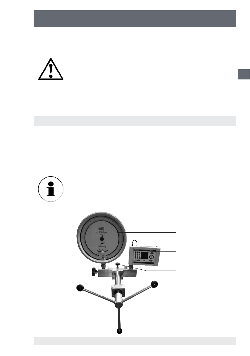
Pompe hydraulique
CPP1000-M/-L
Dans le cas de pressions élevées, il faut s’attendre à une période d’attente plus longue que
pour des pressions plus basses jusqu’à ce que le régime stable soit atteint.
N’ouvrez JAMAIS la robinet d’arrêt brusquement. La robinet ne
doit être ouverte que lorsque la broche a été dévissée entièrement dans le sens inverse des aiguilles d’une montre. (Exeption :
chapitre 3.1.4 Purge du système)
■
Tournez la pompe hydraulique dans le sens inverse des aiguilles d’une montre jusqu’à la
butée pour décharger le système entièrement et n’ouvrez qu’alors la robinet d’arrêt.
■
Maintenant, vous pouvez remplacer l’instrument en test (et/ou l’appareil de référence).
3.3 Manutention de la CPP1000-M/-L avec raccord d‘essai/robinet d‘arrêt
Lors du étalonnage d’appareils à grand volume, une robinet d’arrêt pour les raccords
d’essai est un accessoire utile (voir chapitre 9. Accessoires). Ceci permet d’aspirer
ultérieurement sans problèmes le uide de pression du réservoir dans la pompe et/ou
dans les appareils de contrôle raccordés. Un remplissage préalable de l’instrument en
test/de l’appareil de référence avec le liquide d’exploitation n’est pas nécessaire pour
cela.
Dans le cas d’échantillons d’essai et d’appareils de référence de
grand volume, il est recommandé d’utiliser des robinets d’arrêt pour
les deux raccords d’essai. Dans le cas d’une robinet de réglage n
à pointeau (disponible en série sur CPP1000-L), seule une robinet
d’arrêt peut être montée pour le raccord d’essai.
F
4
5
3
(1) Manivelle
(2) Robinet d'arrêt sur le réservoir
(3) Robinet d'arrêt raccord d'essai
11178035 12/2010 GB/D/F/E
WIKA Mode d'emploi Pompe hydraulique 51
(4) Instrument en test
(5) Appareil de référence
2
1
Page 52

Pompe hydraulique
CPP1000-M/-L
Montage et préparation/Purge du système
■
Monter la robinet d’arrêt (3) hors pression latéralement dans la bride arrière en
remplacement du bouchon d’obturation existant en série (voir chapitre 6. Notice
de montage).
■
Montez l’instrument en test (4) sur le raccord d’essai
F
■
Montez l’appareil de référence (5) sur le deuxième raccord d’essai
■
Reposez le couvercle du réservoir et remontez la robinet de vidange (2). Cependant,
laissez encore la robinet ouverte !
■
Fermez la robinet ou les robinets d’arrêt pour raccord d’essai (3) en tournant dans le
sens des aiguilles d’une montre
■
Dévissez la roue à broche (1) complètement dans le sens inverse des aiguilles
d’une montre.
1) Fermez la robinet d‘arrêt sur le réservoir (2).
2) Ouvrez la robinet ou les robinets d‘arrêt pour raccord d‘essai (3) en tournant dans le
sens inverse des aiguilles d‘une montre (moins d‘un tour sut).
3) Vissez la roue à broche (1) dans le sens des aiguilles d‘une montre jusqu‘à ce que
l‘instrument en test et/ou l‘appareil de référence ache une pression d‘env. 50 à 100
bars.
4) Ouvrez la robinet sur le réservoir (2) tout doucement et avec précaution. Vous voyez
éventuellement des bulles ‚air qui s‘échappent.
5) Fermez la robinet sur le réservoir (2).
6) Fermez la robinet ou les robinets d‘arrêt pour raccord d‘essai (3) en tournant dans le
sens des aiguilles d‘une montre.
7) Dévissez la roue à broche (1) complètement dans le sens inverse des aiguilles
d‘une montre.
■
Répétez les étapes 1 à 7) encore quelques fois.
Exploitation
■
Ouvrez la robinet d’arrêt sur le raccord d’essai (3) et fermez la robinet d’arrêt sur
le réservoir (2).
■
Vissez la roue à broche dans le sens des aiguilles d’une montre. Le uide de service
est envoyé dans l’instrument en test raccordé.
■
Si l’appareil de mesure raccordé n’est pas encore assez rempli et/ou si la pression
nécessaire n’a pas encore été atteinte, fermez la robinet d’arrêt sur l’instrument en
test (3).
■
Ouvrez la robinet d’arrêt sur le réservoir (2) et tournez la roue à broche dans le sens
inverse des aiguilles d’une montre jusqu’à la butée. Le nouveau uide est aspiré du
réservoir dans le cylindre.
■
Fermez la robinet d’arrêt sur le réservoir (2).
■
Ouvrez la robinet d’arrêt sur l’instrument en test (3).
■
Revissez la roue à broche dans le sens des aiguilles d’une montre.
■
La procédure décrite doit être répétée jusqu’à ce que la pression requise soit atteinte.
WIKA Mode d'emploi Pompe hydraulique52
11178035 12/2010 GB/D/F/E
Page 53
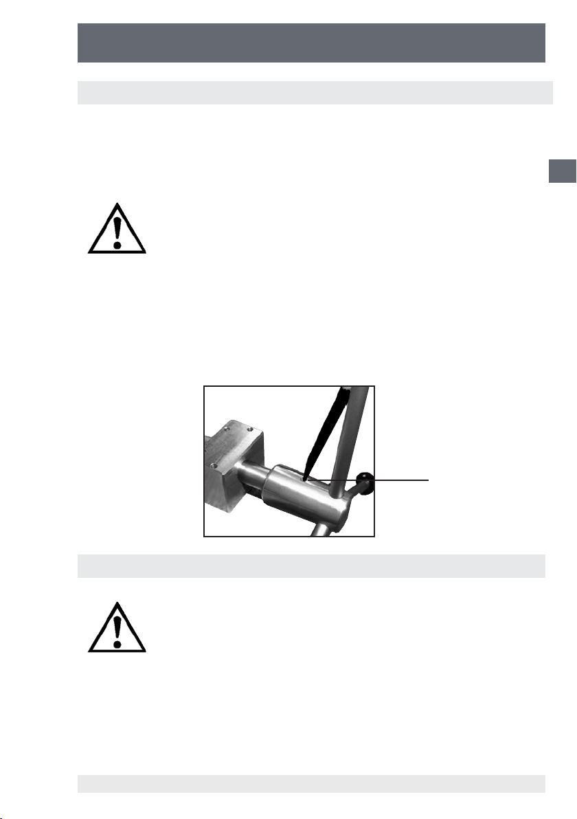
Pompe hydraulique
CPP1000-M/-L
3.4 Démontage
■
Après l‘enregistrement de tous les points de poussée (après la n de le étalonnage
de l‘instrument en test), dévissez complètement la broche et ouvrez la robinet.
■
Maintenant, vous pouvez démonter l‘instrument en test (et éventuellement l‘appareil
de référence) du raccord de pression.
Ne démontez l‘instrument en test et/ou l‘appareil de référence
que lorsque la pression dans la pompe hydraulique est entièrement tombée.
■
Pour retirer le manivelle de la pompe hydraulique, appuyez l‘élément de pression
à ressort au moyen d‘un petit tournevis ou d‘un stylo vers le bas, maintenant, vous
pouvez sortir le manivelle vers l‘avant.
■
Nous recommandons de procéder à une purge complète de la pompe hydraulique
avant son transport. Les raccords d‘essai devraient être fermés par des bouchonsborgnes. (Voir chapitre 9. Accessoires)
F
Elément de pression
à ressort
4. Mesures en cas de dérangements
Si des dérangements ne peuvent pas être éliminés à l‘aide de
la notice d‘emploi, l‘appareil doit immédiatement être mis hors
service et le fabricant doit être contacté. Les réparations ne
doivent être exécutées que par le fabricant. Il n‘est pas admissible que des opérations et modications soient réalisées sur
l‘appareil par l‘exploitant.
En cas de dérangements qui sont dus à des défauts de l‘équipement hydraulique, les
opérateurs doivent immédiatement informer leur supérieur et faire appel à du person-
nel technique qualié et autorisé pour réaliser la maintenance.
11178035 12/2010 GB/D/F/E
WIKA Mode d'emploi Pompe hydraulique 53
Page 54

Pompe hydraulique
CPP1000-M/-L
Tableau : Description des défauts et mesures
Type de défaut : Mesures :
■
I. Pas de mise sous pression
possible/Fuite dans le
F
système
II. Pas de mise sous pression
possible et/ou impossible
d'atteindre la pression
maximale
III. Chute lente de la pression
Bien fermer la robinet d'arrêt sur le réservoir.
■
Contrôlez si les joints dans les raccords de
pression sont en excellent état et bien posés.
■
Après le montage de l'instrument en test et
de l'appareil de référence, des inclusions d'air
peuvent se trouver dans le système.
Attention : le système doit être purgé avant le
début du étalonnage. Procédez comme décrit
dans les chapitres 3.1.2 à 3.1.4.
■
Ensuite remettre sous pression
REMARQUE : dans le cas de circuits de étalonnage avec volume important, un remplissage
préalable de l'instrument en test et éventuellement de l'appareil de référence ou l'utilisation de
la robinet d'arrêt pour raccord d'essai disponible
en accessoire (voir chapitre 9. Accessoires) est
recommandé.
■
Fuite dans le système, voir point I.
■
Si des composants minimes de l'air sont
encore compactés dans le système, la
pression de contrôle générée tombe d'abord
un peu, il est alors nécessaire de refaire le
réglage en conséquence.
■
Si le système a été mis rapidement sous
pression, un certain temps est nécessaire
(< 1 minute) pour qu'il puisse se stabiliser
thermiquement. Le réglage de la pression doit
alors être ajusté en conséquence.
■
Après le montage de l'instrument en test et
de l'appareil de référence, des inclusions d'air
peuvent se trouver dans le système. Voir le
point II :
■
Ensuite remettre sous pression
Vous obtiendrez des renseignements complémentaires auprès du département
technique de contrôle et de étalonnage de WIKA.
WIKA Mode d'emploi Pompe hydraulique54
11178035 12/2010 GB/D/F/E
Page 55

Pompe hydraulique
CPP1000-M/-L
5. Entretien et maintenance
Pour le nettoyage, la pompe hydraulique peut être frottée avec un chion légèrement
mouillé. Aucun travail de maintenance ne doit être exécuté sur la pompe hydraulique.
Dans le cas d’usure sensible, elle doit être envoyée au fabricant pour révision (après
devis).
5.1 Pièces d’usure
Les joints d’étanchéité toriques dans les raccords de pression sont soumis à l’usure.
Les deux joints d’étanchéité toriques doivent être contrôlés quant à leur bon positionnement et à leur usure avant chaque étalonnage. Les joints d’étanchéité toriques
devront éventuellement être remplacés à intervalles réguliers (voir chapitre 9. Accessoires).
Seuls des joints d’origine doivent être utilisés. Des joints
présentant des dimensions ou des matériaux et/ou des
trempes divergeants peuvent entraîner des dommages sur
l’appareil ou sur l’instrument en test et/ou sur l’appareil de
référence et représentent un danger pour l’opérateur.
5.2 Remplacement du liquide d’exploitation
F
Nous vous recommandons vivement de remplacer le liquide d’exploitation en cas de
souillure visible.
Vidanger le liquide d’exploitation
■
Ouvrez la robinet d’arrêt, dévissez la complètement.
■
Retirez le couvercle transparent du réservoir.
■
Aspirez le liquide du réservoir, par exemple avec une seringue appropriée.
■
De plus, lorsque la robinet d’arrêt est fermée, de petites quantités résiduelles
peuvent être aspirées au niveau des raccords en tournant doucement la pompe
hydraulique.
■
De minimes quantités résiduelles d’huile peuvent rester dans la pompe.
L’élimination de l’huile usagée doit être faite conformément
aux prescriptions légales.
■
Pour procéder au nouveau remplissage et à la purge du système, procédez comme
11178035 12/2010 GB/D/F/E
décrit dans les chapitres 3.1.2 à 3.1.4.
WIKA Mode d'emploi Pompe hydraulique 55
Page 56

Pompe hydraulique
CPP1000-M/-L
6. Notice de montage pour des robinets d’arrêt pour rac-
cord d’essai et robinet de réglage n à pointeau
La notice de montage décrit la pose ultérieure
F
de la robinet d'arrêt pour raccord d'essai
(n° de commande 11208384) ou de la robinet
de réglage n à pointeau (n° de commande
11248351). Les robinets peuvent être posées
latéralement dans la bride postérieure en remplacement des bouchons-borgnes existant en série.
Les possibilités de combinaison suivantes existent pour chaque type de pompe :
Robinet d'arrêt pour
raccord d'essai
1 avec 0
0 avec 1
CPP1000-M
Robinet d'arrêt pour
CPP1000-L
Dans le cas où seul un manomètre grand volume est monté sur la pompe
CPP1000-M, seule une robinet d’arrêt est normalement nécessaire pour le raccord
d’essai. Si l’instrument en test et l’appareil de référence disposent d’un grand volume,
nous recommandons l’utilisation de deux robinets d’arrêt.
Dans le cas de l’emploi de 2 robinets d’arrêt, la pose d’une robinet de réglage n
à pointeau n’est pas possible.
1 avec 1
2 avec 0
raccord d'essai
1 avec disponible en série
0 avec disponible en série
Robinet de réglage n à
pointeau
Robinet de réglage n à
pointeau
11178035 12/2010 GB/D/F/E
WIKA Mode d'emploi Pompe hydraulique56
Page 57
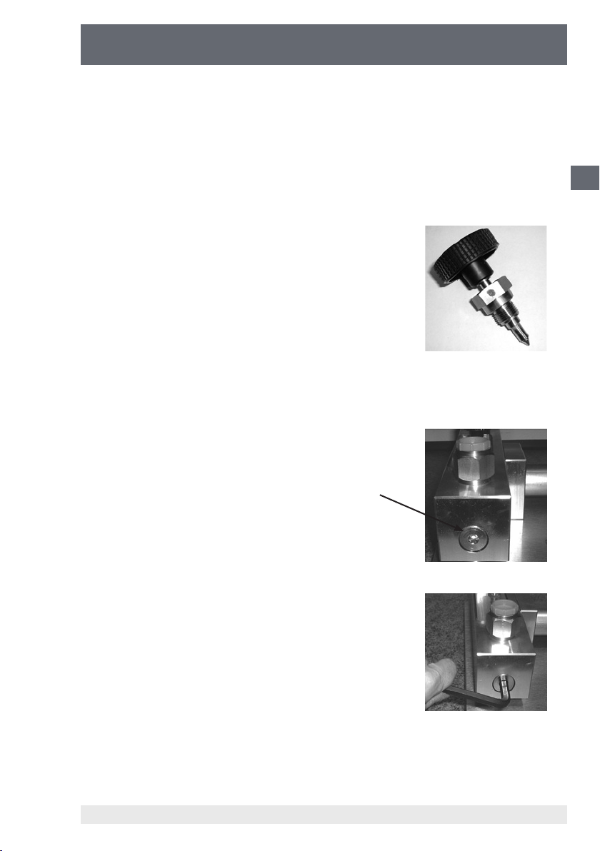
Pompe hydraulique
CPP1000-M/-L
Pour le montage, vous avez besoin de l'outillage suivant :
■
Clé mâle à six pans 8 mm
■
Clé à fourche de 27
■
Pincette
Veuillez contrôler l'équipement livré :
■
1 vanne avec joints intégrés
Vue latérale de la pompe hydraulique avec vue sur le bouchon-borgne
à six pans creux :
F
bouchon-borgne
à six pans creux
Débloquez le bouchon-borgne avec une clé mâle
à six pans de 8 mm et dévissez le bouchonborgne.
11178035 12/2010 GB/D/F/E
WIKA Mode d'emploi Pompe hydraulique 57
Page 58

Pompe hydraulique
CPP1000-M/-L
Après que le bouchon-borgne a été dévissé, un
petit corps cylindrique rouge en plastique est
reconnaissable à l'intérieur.
Il s'agit ici d'un raccord de réduction de volume
(réduit le volume à l'intérieur de la pompe lorsque
F
la robinet d'arrêt ou la robinet de réglage n à
pointeau n'est pas posée).
Sortez le morceau de plastique rouge avec une
pincette ou souez-le à l'air comprimé via le
raccord d'essai ouvert.
Vissez alors la robinet d'arrêt ou de réglage n à
pointeau dans la pompe hydraulique.
Serrez bien la robinet en utilisant une clé à
fourche de 27.
Vous pouvez éliminer les pièces suivantes qui
sont inutiles :
■
bouchon-borgne
■
corps rouge cylindrique
11178035 12/2010 GB/D/F/E
WIKA Mode d'emploi Pompe hydraulique58
Page 59

Pompe hydraulique
CPP1000-M/-L
7. Caractéristiques techniques
CPP1000-M CPP1000-L
Plage de pression bars 0 ... 1000
Fluide Liquides hydrauliques sur la base d‘huile minérale / eau propre
sans calcaire
Raccords de pression 2 letages intérieurs G ½“, non freinés, avec joint d'étanchéité
torique
Distance des raccords d mm 200 115
Réservoir de liquide cm³ 110 55
Diamètre du piston mm 8
Cylindrée par tour cm³ env. 0,1
Cylindrée totale cm³ env. 3,9
Réglage n de la pression Option, voir Accessoires Robinet de rég. n à pointeau latérale
Eort à
- 250 bars Nm 2,0
- 500 bars Nm 4,0
- 1000 bars Nm 8,0
Matériau
- Piston Acier CrNi
- Cylindre Laiton
- Bride arrière Aluminium
- Joints FKM et NBR; en option EPDM
Fixation stationnaire Deux alésages de passage dans la bride antérieure Ø 6,4 mm
Dimensions mm 420 (L) x 280 (l) x 103 (H) 420 (L) x 240 (l) x 103 (H)
Poids kg 6,3 5,6
1) Autres uides de transmission de la pression sur demande.
1)
F
11178035 12/2010 GB/D/F/E
WIKA Mode d'emploi Pompe hydraulique 59
Page 60
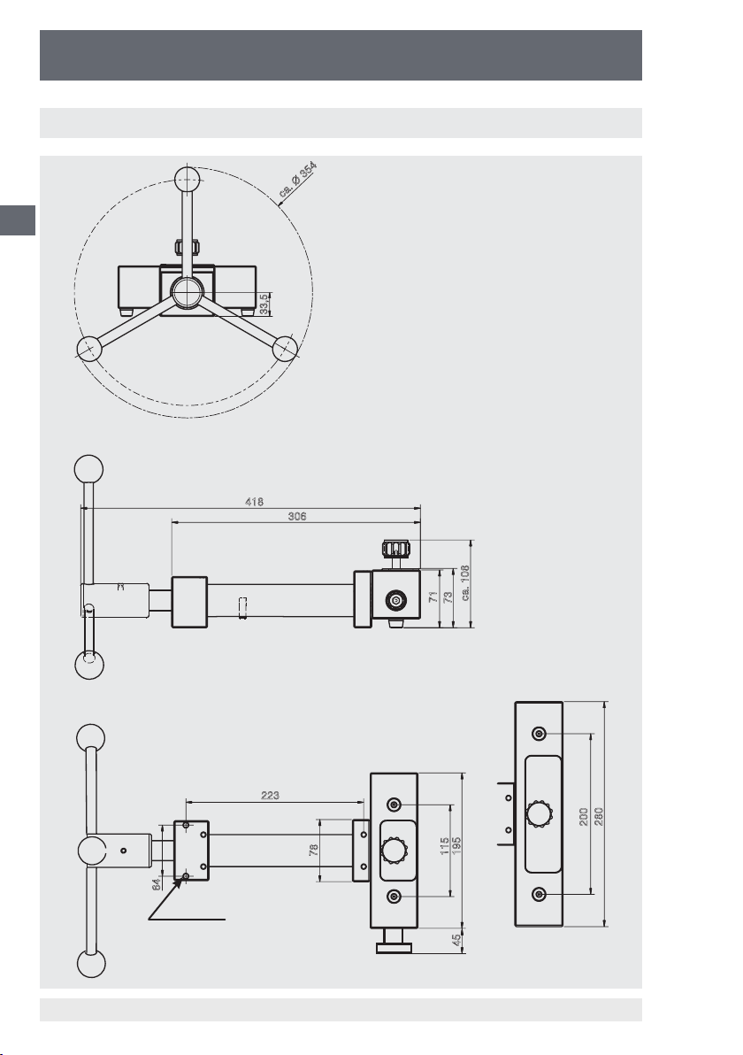
Pompe hydraulique
CPP1000-M/-L
8. Dimensions
F
ca. Ø 354
33,5
418
306
64
2 x Ø 6,4
223
78
CPP1000-L
WIKA Mode d'emploi Pompe hydraulique60
ca. 108
71
73
280
200
195
115
45
CPP1000-M
11178035 12/2010 GB/D/F/E
Page 61

Pompe hydraulique
CPP1000-M/-L
9. Données relatives à la commande / Accessoires
Accessoires N° de commande
Pompe hydraulique CPP1000-M 12401447
Pompe hydraulique CPP1000-L, version portable y compris
robinet de réglage n à pointeau et couvercle de réservoir
étanche
Huile spéciale pour la série de pompes d'essai CPP1000 et
CPP1600 dans bouteille en plastique, contenu 1 litre
Robinet d'arrêt pour raccord d'essai pour remplir facilement
des appareils grand volume de uide de remplissage directement sur la pompe hydraulique.
Pression admissible : 1000 bars max.
Pour des échantillons d'essai et des appareils de référence
grand volume, il est recommandé d'utiliser 2 robinets d'arrêt.
Robinet de réglage n à pointeau pour pose ultérieure dans
la pompe CPP1000-M ; permet le positionnement exact par
rapport aux points de mesure.
Bouchon-borgne avec letage extérieur G ½, matériau : laiton 11155230
Kit de joints d'étanchéité toriques composé de 10 joints de
rechange pour les raccords d'essai - matériau : FKM/FPM
Adaptateur pour letage - letage extérieur G ½ sur letage
intérieur G ⅛, matériau : laiton
Adaptateur pour letage - letage extérieur G ½ sur letage
intérieur G ¼, matériau : laiton
Adaptateur pour letage - letage extérieur G ½ sur letage
intérieur G ⅜, matériau : laiton
Adaptateur pour letage - letage extérieur G ½ sur letage
intérieur M20 x 1,5, matériau : laiton
Adaptateur pour letage - letage extérieur G ½ sur letage
intérieur ¼ NPT, matériau : laiton
Adaptateur pour letage - letage extérieur G ½ sur letage
intérieur ½ NPT, matériau : laiton
Raccord angulaire 90° pour les échantillons d'essai avec
point de raccordement sur l'arrière
12677133
2099882
11208384
11248351
12422487
9090207
9090231
9090266
9090355
0187119
0187143
1564838
F
11178035 12/2010 GB/D/F/E
WIKA Mode d'emploi Pompe hydraulique 61
Page 62

Pompe hydraulique
CPP1000-M/-L
F
11178035 12/2010 GB/D/F/E
WIKA Mode d'emploi Pompe hydraulique62
Page 63
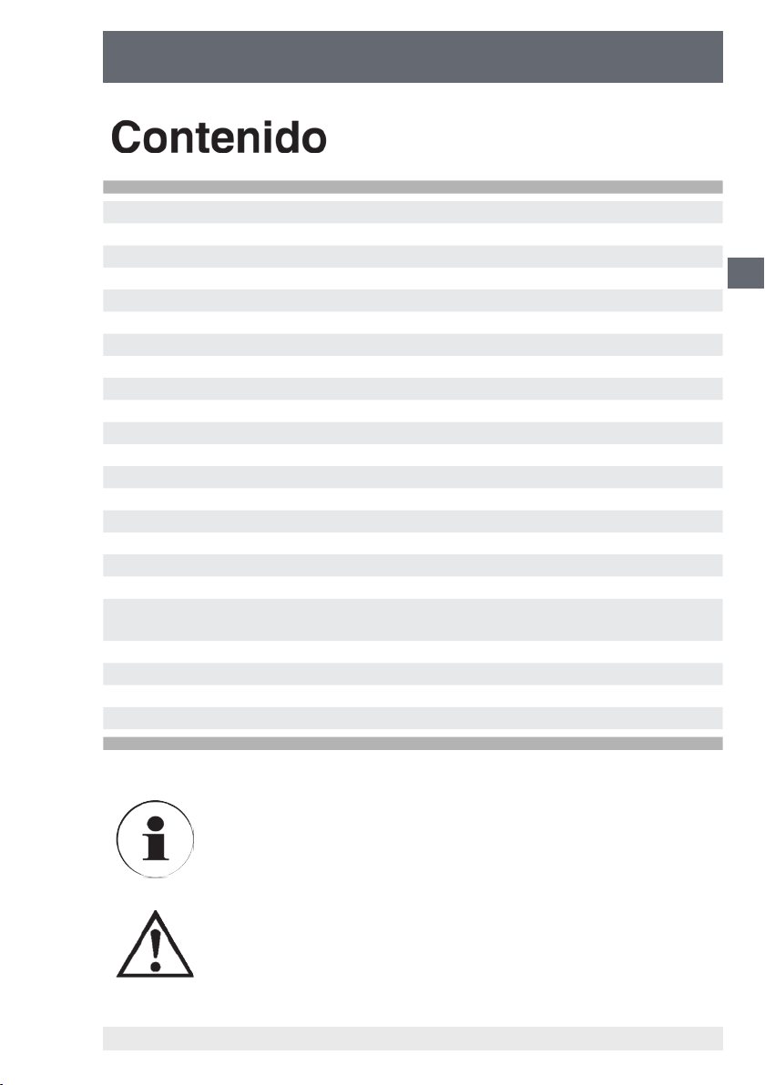
Bomba manual de husillo
CPP1000-M/-L
Contenido
1. Información general 64
1.1 Instrucciones generales de seguridad 64
2. Descripción del producto 65
2.1 Informaciones generales sobre el producto 65
2.2 Posición de los elementos de control 66
3. Puesta en servicio y funcionamiento 66
3.1 Preparación 66
3.1.1 Instalación del aparato 66
3.1.2 Llenado del sistema con líquido de servicio 67
3.1.3 Conexión de los manómetros (referencia y probeta) 67
3.1.4 Ventilación del sistema 69
3.2 Servicio 70
3.3 Manejo de la CPP1000-M/-L con conexión de prueba/válvula de cierre 71
3.4 Desmontaje 73
4. Medidas en caso de fallos 73
5. Cuidado y mantenimiento 75
5.1 Piezas de desgaste 75
5.2 Cambio del líquido de servicio 75
6. Instrucciones de instalación de la válvula de cierre para la
conexión de prueba y la válvula de regulación na
7. Datos técnicos 79
8. Dimensiones 80
9. Datos de pedido / accesorios 81
10. Direcciones 83
76
E
Información
Este signo indica informaciones, notas o consejos.
¡Advertencia!
Este símbolo indica advertencias relativas a acciones que
puedan dañar personas y a la instalación.
11178035 12/2010 GB/D/F/E
WIKA Manual de instrucciones Bomba manual de husillo 63
Page 64

Bomba manual de husillo
CPP1000-M/-L
1. Información general
En los capítulos siguientes hay informaciones más detalladas sobre la bomba manual
de husillo CPP1000-M/-L y su utilización correcta.
y en caso de problemas particulares no explicados detalladamente en el manual de
instrucciones, contactar las direcciones alistadas en la última página.
E
La garantía de la
condiciones de suministro de la ZVEI (Asociación federal de la industria electrotécnica). En caso de manejo incorrecto, al no respetar el manual de instrucciones, al abrir
el aparato y al soltar racores se pierden todos los derechos de garantía.
Además señalamos que el contenido de este manual de instrucciones no es parte de
un acuerdo, una conrmación o relaciones jurídicas precedentes o existentes ni debe
modicarlos.
Todas las obligaciones de la empresa WIKA Alexander Wiegand SE & Co. KG resultan del contrato de compraventa correspondiente y de las condiciones comerciales
generales de WIKA Alexander Wiega WIKA es una marca registrada de WIKA Alexander Wiegand SE & Co. KG.
Los nombres de las empresas y de los productos mencionados en este manual son
marcas registradas del fabricante.
bomba manual de husillo CPP1000-M/-L
Para obtener más informaciones
es de 2
4 meses según las
Nos reservamos el derecho a realizar modicaciones aceptables que sirvan a la mejora
técnica.
Está prohibido reproducir el manual o partes de ello.
© 2006 copyright WIKA Alexander Wiegand SE & Co. KG
1.1 Instrucciones generales de seguridad
Leer este manual de instrucciones cuidadosamente antes de
utilizar la bomba manual de husillo CPP1000-M/-L. El funcionamiento y la seguridad de funcionamiento del aparato puede
garantizarse sólo si se observan las instrucciones de seguridad del manual de instrucciones.
1. ¡La bomba manual de husillo CPP1000-M/-L debe ser manejada por especialistas
instruidos y autorizados que conocen y saben trabajar según el manual de instrucciones!
2. Sólo respetando las condiciones descritas en el capítulo "Instalación del aparato"
se garantiza el funcionamiento perfecto y la seguridad de funcionamiento de la
bomba manual de husillo CPP1000-M/-L.
WIKA Manual de instrucciones Bomba manual de husillo64
11178035 12/2010 GB/D/F/E
Page 65

Bomba manual de husillo
CPP1000-M/-L
3. Siempre hay que tratar la bomba manual de husillo CPP1000-M/-L con el cuidado necesario para instrumentos de precisión (proteger contra humedad, golpes
y temperaturas extremas). Hay que tratar la bomba con cuidado (no tirarla, no
abrirla con fuerza, etc) y protegerla contra suciedad. En todo caso evitar el uso de
la fuerza en los elementos de control (rueda de husillo, válvula, conexiones de la
probeta) de la bomba manual de husillo CPP1000-M/-L.
4. Después de transportar el aparato de un ambiente frío a un ambiente caliente, hay
que esperar que la temperatura del aparato se adapte a la temperatura ambiental
antes de ponerlo otra vez en servicio.
5. Si se supone que ya no es posible utilizar el aparato sin riesgos, hay que ponerlo
fuera de servicio y protegerlo con una señal para que no sea repuesto en servicio.
El aparato puede perjudicar la seguridad del usuario, si p.ej.:
■
Demuestra daños visibles
■
Ya no funciona como está prescrito
■
Ha sido almacenado en condiciones inadecuadas por mucho tiempo
En caso de duda, siempre enviar el aparato al fabricante para trabajos de reparación o
mantenimiento.
6. El cliente no debe realizar modicaciones ni reparaciones en el aparato. Si se
abre el aparato o si se sueltan las piezas de montaje o los racores, esto perjudica
la seguridad de funcionamiento y es peligroso para el usuario. Para trabajos de
mantenimiento y reparación hay que enviar el aparato al fabricante.
7. Sólo utilizar piezas originales en el aparato.
8. Utilizar el aparato de otro modo que descrito en las instrucciones siguientes o fuera
de las especicaciones no es conforme a lo prescrito y por eso debe ser excluido.
E
2. Descripción del producto
2.1 Informaciones generales sobre el producto
■
Utilización
Las bombas manuales de husillo sirven para la generación de presión para controlar, ajustar y calibrar manómetros mecánicos y electrónicos mediante mediciones de comparación. Es posible efectuar estas pruebas de presión de manera
estacionaria en el laboratorio o en el taller o directamente en el lugar del punto de
medición.
11178035 12/2010 GB/D/F/E
WIKA Manual de instrucciones Bomba manual de husillo 65
Page 66

Bomba manual de husillo
CPP1000-M/-L
■
Funcionamiento
Si el aparato a probar y un manómetro de referencia sucientemente exacto están
conectados a la bomba manual de husillo, la misma presión acciona sobre ambos
manómetros al activar la bomba. Mediante la comparación de los dos valores de
medición utilizando valores de presión cualquieras, es posible controlar la precisión del manómetro o ajustarlo. La bomba manual de husillo CPP1000-M/-L está
equipada con una rueda de husillo precisamente accionable para aproximarse a
los puntos con exactitud. La bomba CPP1000-M/-L se caracteriza por un husillo
E
de trabajo dentro del cuerpo de la bomba. De este modo se suprime un momento
de exión negativo en un husillo desenroscado y en particular para la utilización
in situ es ventajoso que la posición de la bomba no varíe por la rotación del husillo
durante el servicio.
2.2 Agrupación de los elementos de control
Depósito de almacenamiento
de medios y válvula de cierre
2 conexiones de presión
G½ para manómetros
(referencia y probeta)
2 oricios 6,4 mm para la
jación estacionaria
Pieza a presión de muelle
Palanca cruciforme
Depósito de almacenamiento
de medios (estanco) y válvula
de cierre
Válvula de
regulación
na
CPP1000-M CPP1000-L
3. Puesta en servicio y funcionamiento
3.1 Preparación
3.1.1 Instalación del aparato
■
Colocar la bomba manual de husillo sobre una base ja. Evitar un posicionamiento
inestable. En caso necesario es posible jarla de manera estacionaria en una placa
de base o un banco de trabajo con tornillos adecuados. Para eso hay dos oricios
(Ø 6,4 mm) en la brida delantera.
11178035 12/2010 GB/D/F/E
WIKA Manual de instrucciones Bomba manual de husillo66
Page 67

Bomba manual de husillo
CPP1000-M/-L
■
Insertar la palanca cruciforme con los mangos en la bomba. Asegurarse de que la
pieza de presión del resorte encaje en el casquillo de la palanca cruciforme.
3.1.2 Llenado del sistema con líquido de servicio (primera puesta en servicio)
Como líquido de servicio para la CPP1000-M/-L utilizar
solamente:
■
Líquidos hidráulicos a base de aceite mineral
■
Agua limpia y libre de cal
¡Agua destilada y líquidos a base de agua para aparatos
hidráulicos no son aptos!
Otros medios de transmisión de presión bajo demanda.
Llenar la bomba con líquido de servicio como sigue:
■
Enroscar el husillo completamente en el sentido de las agujas del reloj.
■
Abrir la válvula de cierre, desenroscar completamente y quitar la tapa del recipiente
de almacenamiento.
■
Llenar ambas conexiones a presión de forma alterna con el líquido de servicio con
cuidado y despacio. Es posible observar como el líquido de servicio entra en el
recipiente. Verter el líquido en las conexiones de presión hasta que el recipiente
esté llenado entre la mitad y tres cuartos.
■
Colocar otra vez la tapa del recipiente de almacenamiento y montar la válvula de
descarga.
E
3.1.3 Conexión de los manómetros (referencia y probeta)
■
Las conexiones de presión tienen una rosca hembra G ½.
Al calibrar aparatos con otras roscas de conexión, hay que utilizar
adaptadores de rosca correspondientes. (Véase el capítulo 9. Accesorios)
■
Antes de sujetar el manómetro de presión de referencia y el comprobante hay
que desairear el sistema. Girar con cuidado la rueda de husillo en el sentido de
las agujas del reloj mientras las conexiones están abiertas para bombear el aceite
en el sistema. Hay que girar hasta que el aceite se encuentre en las juntas tóricas
de las conexiones abiertas y no salgan bolas de aire. La válvula de cierre en el
recipiente de almacenamiento debe estar cerrada y las válvulas de cierre eventual-
11178035 12/2010 GB/D/F/E
mente montados para las conexiones de prueba deben estar abiertas.
WIKA Manual de instrucciones Bomba manual de husillo 67
Page 68

Bomba manual de husillo
CPP1000-M/-L
■
Insertar sucesivamente un manómetro de referencia y el aparato a probar (probeta) en una de ambas conexiones de presión de la CPP1000-M/-L. Las conexiones
están libres para posibilitar la colocación del aparato en modo de garantizar una
lectura perfecta. Una junta tórica ya existe. No se necesita material obturador
adicional. Para una estanqueidad segura es suciente con apretar a mano.
■
Como accesorio está disponible una pieza de conexión angular para probar aparatos con conexión trasera (véase el capítulo 9. Accesorios).
E
Junta tórica
Controlar si la junta tórica en las conexiones de presión está
bien colocadas o desgastadas y cambiarlas si fuera necesa-
rio. (Véase el capítulo 9. Accesorios)
Asegurarse de que el interior de cada aparato a conectar sea
limpio.
En circuitos de calibración con un volumen más grande se aconseja
llenar anticipadamente el líquido de servicio en la probeta/referencia
o utilizar la válvula de cierre para la conexión de prueba, disponible
como accesorio
Ejemplo: Construcción de calibración CPP1000-M/-L con calibrador de procesos CPH6000 como aparato de referencia y transformador de medición de
presión como probeta.
WIKA Manual de instrucciones Bomba manual de husillo68
11178035 12/2010 GB/D/F/E
Page 69

Bomba manual de husillo
CPP1000-M/-L
3.1.4 Ventilación del sistema
Después de sujetar los instrumentos todavía pueden encontrarse bolsas de aire en el
sistema. Antes de iniciar la calibración, desairear el sistema de la forma siguiente:
■
Abrir la válvula de cierre en el recipiente de almacenamiento.
■
Desenroscar la rueda de husillo completamente en el sentido contrario de las
agujas del reloj.
■
Cerrar la válvula.
1) Girar la rueda de husillo en el sentido de las agujas del reloj hasta que la probeta
y/o la referencia indique(n) un valor de presión de aprox. 50 a 100 bares.
Si no se alcanza un aumento de presión después de enroscar
el husillo completamente en el sentido de las agujas del reloj, el
volumen de prueba conectado es demasiado grande y hay que
llenar el líquido de servicio en los aparatos antes de conectarlos
con la bomba o hay que trabajar con la válvula de cierre para la
conexión de prueba, disponible como accesorio (véase el capítulo
9. Accesorios).
2) Abrir la válvula muy despacio y con cuidado. Es posible que salgan burbujas.
3) Cerrar otra vez la válvula.
4) Continuar a girar la rueda de husillo en el sentido de las agujas del reloj hasta que
la probeta y/o referencia indique(n) otra vez un valor de 50 a 100 bares.
5) Abrir la válvula muy despacio y con cuidado. Es posible que se vea otra vez salir
burbujas.
6) Cerrar otra vez la válvula.
7) Completamente desenroscada la rueda del husillo en sentido contrario a las agujas
del reloj
8) Abrir la válvula.
9) Cerrar la válvula después de aprox. 10 segundos.
E
■
Si fuera necesario repetir otra vez los pasos 1) hasta 9).
Ahora la bomba manual de husillo CPP1000-M/-L está lista para el
servicio.
Si se utilizan probetas o aparatos de referencia con un volumen muy
grande, se aconseja llenar anticipadamente el líquido de servicio o
utilizar la válvula de cierre para la conexión de prueba, disponible
como accesorio (véase el capítulo 9. Accesorios).
11178035 12/2010 GB/D/F/E
WIKA Manual de instrucciones Bomba manual de husillo 69
Page 70

Bomba manual de husillo
CPP1000-M/-L
3.2 Servicio
La presión máxima admisible de la CPP1000-M/-L es 1000
bar. Presiones más altas pueden dañar la bomba. No sobre-
cargar el instrumento de medición de referencia, la probeta
y las mangueras de conexión eventualmente instaladas con
presión demasiado alta.
E
■
Se recomienda siempre desenroscar completamente el husillo (en el sentido
contrario de las agujas del reloj) al empezar la medición para proveer bastante
volumen para la medición.
■
Girar la palanca cruciforme en el sentido de las agujas del reloj para aumentar la
presión de prueba.
■
Girar la palanca cruciforme en el sentido contrario de las agujas del reloj para
reducir la presión de prueba.
■
Si se utiliza una válvula de regulación na (generalmente integrada en la
CPP1000-L), es posible ajustar con precisión la presión preajustada enroscando o
desenroscando la válvula.
■
La indicación del manómetro a probar puede compararse en cada punto de calibración con el instrumento de medición de referencia.
Si se comprimen también pocas partículas de aire en el sistema, la
presión generada primero se reduce un poco y debe ser reajustada.
Con presiones altas es necesario esperar más que con presiones bajas hasta alcanzar el estado de equilibrio.
NUNCA abrir de golpe la válvula de cierre mientras hay
presión. La válvula sólo debe abrirse si el husillo está desenroscado completamente en el sentido contrario de las agujas
del reloj. (Excepción: capítulo 3.1.4 Ventilación del sistema)
■
Desenroscar la bomba manual de husillo en el sentido contrario de las agujas
del reloj hasta el tope para descargar completamente el sistema y sólo ahora abrir
la válvula de cierre.
■
Ahora puede cambiarse la probeta (y/o el instrumento de referencia).
WIKA Manual de instrucciones Bomba manual de husillo70
11178035 12/2010 GB/D/F/E
Page 71
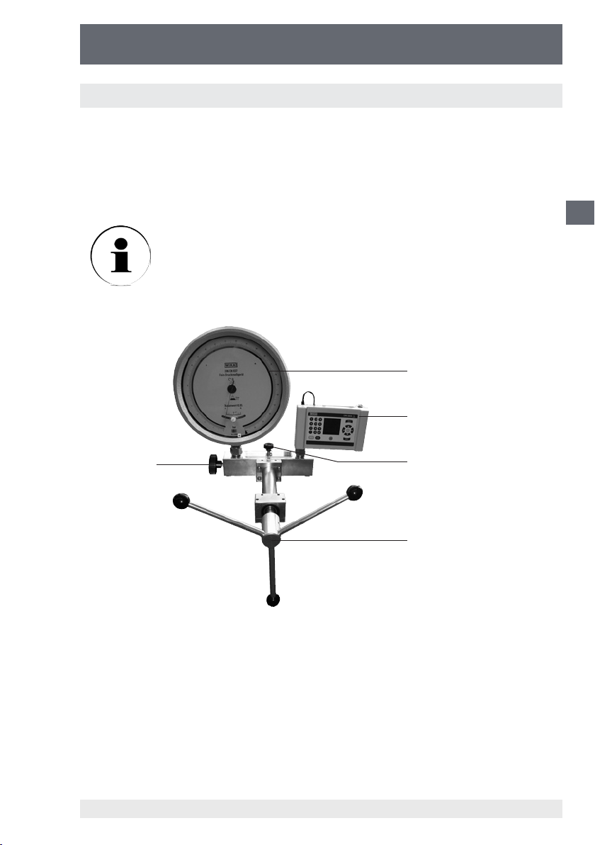
Bomba manual de husillo
CPP1000-M/-L
3.3 Manejo de la CPP1000-M/-L con conexión de prueba/válvula de cierre
Una válvula de cierre para las conexiones de prueba es un accesorio útil para calibrar
aparatos de gran volumen (véase el capítulo 9. Accesorios). La válvula hace posible
reaspirar sin problemas el medio de presión del recipiente de almacenamiento a la
bomba o a los aparatos de prueba conectados. No es necesario llenar anticipadamente el líquido de servicio en la probeta/referencia.
Se recomienda utilizar válvulas de cierre para ambas conexiones de
prueba en caso de probetas y instrumentos de referencia de gran
volumen.
Si una válvula de regulación na está instalada (generalmente
integrada en la CPP1000-L), sólo es posible montar una válvula de
cierre para la conexión de prueba.
4
5
E
3
(1) Palanca cruciforme
(2) Válvula de cierre en el recipiente de almacenamiento
(3) Válvula de cierre en la conexión de prueba
(4) Probeta
(5) Instrumento de referencia
11178035 12/2010 GB/D/F/E
WIKA Manual de instrucciones Bomba manual de husillo 71
2
1
Page 72

Bomba manual de husillo
CPP1000-M/-L
Montaje y preparación/ventilación del sistema
■
Montar la válvula de cierre (3) en estado sin presión en la brida trasera en lugar del
tornillo tapón generalmente integrado (véase el capítulo 6. Instrucción de instalación).
■
Montar la probeta (4) en la conexión de prueba
■
Montar el instrumento de referencia (5) en la segunda conexión de prueba
■
Colocar otra vez la tapa del recipiente de almacenamiento y montar la válvula de
E
cierre (2). ¡Dejar la válvula abierta!
■
Cerrar la(s) válvula(s) de cierre para la conexión de prueba (3) girando en el sentido de las agujas del reloj.
■
Completamente desenroscar la rueda de husillo (1) en el sentido contrario de las
agujas del reloj.
1) Cerrar la válvula de cierre en el recipiente de almacenamiento (2).
2) Abrir la(s) válvula(s) para la conexión de prueba (3) girando en el sentido contrario
de las agujas del reloj (menos que una vuelta es suciente).
3) Enroscar la rueda de husillo (1) en el sentido de las agujas del reloj hasta que la
probeta y/o la referencia indique(n) un valor de presión de aprox. 50 a 100 bares.
4) Abrir muy despacio y con cuidado la válvula en el recipiente de almacenamiento
(2). Es posible que salgan burbujas.
5) Cerrar la válvula en el recipiente de almacenamiento (2).
6) Cerrar la(s) válvula(s) de cierre para la conexión de prueba (3) girando en el sentido de las agujas del reloj.
7) Desenroscar completamente la rueda del husillo (1) en el sentido contrario de las
agujas del reloj.
■
Repetir algunas veces los pasos 1) a 7).
Servicio
■
Abrir la válvula de cierre en la conexión de prueba (3) y cerrar la válvula de cierre
en el recipiente de almacenamiento (2).
■
Enroscar la rueda de husillo en el sentido de las agujas del reloj. Se empuja el
medio de servicio a la probeta conectada.
■
Cerrar la válvula de cierre en la probeta (3) si el instrumento de medición conectado no está bastante lleno o si no se ha alcanzado la presión deseada.
■
Abrir la válvula de cierre en el recipiente de almacenamiento (2) y enroscar la rueda
de husillo en el sentido contrario de las agujas del reloj hasta el tope. Se aspira el
medio nuevo del recipiente de almacenamiento al cilindro.
■
Cerrar la válvula de cierre en el recipiente de almacenamiento (2).
■
Abrir la válvula de cierre en la probeta (3).
■
Enroscar otra vez la rueda de husillo en el sentido de las agujas del reloj.
■
El procedimiento descrito debe repetirse hasta que se alcance la presión deseada.
WIKA Manual de instrucciones Bomba manual de husillo72
11178035 12/2010 GB/D/F/E
Page 73

Bomba manual de husillo
CPP1000-M/-L
3.4 Desmontaje
■
Desenroscar completamente el husillo y abrir la válvula después de establecer
todos los puntos de presión (después de calibrar la probeta).
■
Ahora se puede desmontar la probeta (y en caso necesario la referencia) de la
toma de presión.
Sólo desmontar la probeta y/o el instrumento de referencia si
la presión en la bomba manual de husillo está completamente
suprimida.
■
Para quitar la palanca cruciforme de la bomba manual de husillo empujar la pieza a
presión de muelle hacia abajo con un destornillador pequeño o un bolígrafo. Ahora
es posible extraer la palanca cruciforme.
■
Se recomienda vaciar la bomba completamente antes de transportarla. Hay que
cerrar las conexiones de prueba con tapones obturadores. (Véase el capítulo 9.
Accesorios)
Pieza a presión de muelle
4. Medidas en caso de fallos
E
Inmediatamente poner fuera de servicio el instrumento y
contactar el fabricante si no es posible eliminar los fallos
utilizando el manual de instrucciones. Sólo el fabricante debe
efectuar trabajos de reparación. No se permiten intervenciones y modicaciones en el aparato.
En caso de fallos debido al equipamiento hidráulico, los operadores inmediatamente
deben informar a los superiores y consultar al personal cualicado y autorizado para
efectuar trabajos de mantenimiento.
11178035 12/2010 GB/D/F/E
WIKA Manual de instrucciones Bomba manual de husillo 73
Page 74

Bomba manual de husillo
CPP1000-M/-L
Tabla: Descripción de fallos y medidas
Tipo de fallo: Medidas:
I. No posible establecer la
presión/derrame en el sistema
E
II. No es posible establecer la
presión, o la presión máxima no es
alcanzable
III. Reducción lenta de la presión
■
Cerrar correctamente la válvula de cierre
en el recipiente de almacenamiento.
■
Controlar si las juntas en las tomas de
presión están intactas y si están insertadas correctamente.
■
Después de montar la probeta y la
referencia es posible que haya bolsas de
aire en el sistema.
Atención: Hay que ventilar el sistema antes
de calibrar. Actuar como se describe en los
capítulos 3.1.2 a 3.1.4.
■
Después reestablecer la presión
NOTA: En circuitos de calibración con un
volumen más grande se aconseja llenar
anticipadamente el líquido de servicio en la
probeta y en caso necesario en la referencia
o utilizar la válvula de cierre para la conexión
de prueba (véase el capítulo 9. Accesorios).
■
Derrame en el sistema, véase el punto I.
■
Si se comprimen también pocas partículas de aire en el sistema, la presión de
prueba generada primero se reduce un
poco y debe ser reajustada.
■
Si se introduce rápidamente la presión
en el sistema, el sistema necesita cierto
tiempo (< 1 minuto) para estabilizarse térmicamente. Hay que reajustar la
presión correspondientemente.
■
Después de sujetar la probeta y el instrumento de referencia es posible que haya
bolsas de aire en el sistema. Véase el
punto II:
■
Después reestablecer la presión
Para obtener ayuda, contactar al departamento de prueba y calibración de WIKA.
WIKA Manual de instrucciones Bomba manual de husillo74
11178035 12/2010 GB/D/F/E
Page 75

Bomba manual de husillo
CPP1000-M/-L
5. Cuidado y mantenimiento
Utilizar un paño húmedo para limpiar la bomba manual de husillo. No se deben
efectuar trabajos de mantenimiento en la bomba manual de husillo. En caso de
desgaste evidente hay que enviar la bomba al fabricante para que la regenere
(después de un presupuesto de costes).
5.1 Piezas de desgaste
Las juntas tóricas en las tomas de presión están sujetas al desgaste. Antes de cada
calibración controlar si ambas juntas tóricas están colocadas correctamente o si están
desgastadas. Cambiar las juntas tóricas a intervalos regulares o en caso necesario
(véase el capítulo 9. Accesorios).
Sólo hay que utilizar juntas originales en el aparato. Juntas de
dimensiones, materiales o durezas diferentes pueden dañar el
aparato y la probeta o la referencia y por eso representan un
peligro para el usuario.
5.2 Cambio del líquido de servicio
E
Recomendamos cambiar el líquido de servicio en caso de impuricación visible.
Sacar el líquido de servicio
■
Abrir la válvula de cierre, desenroscarla completamente.
■
Quitar la tapa transparente del recipiente.
■
Aspirar el líquido del recipiente de almacenamiento, p. ej. con una jeringa apropiada.
■
Adicionalmente es posible aspirar pequeñas cantidades de aceite residual en las
conexiones atornillando lentamente la bomba manual de husillo.
■
Pequeñas cantidades de aceite residual pueden quedarse en la bomba.
Hay que eliminar los aceites usados según las prescripciones
legales.
■
Para rellenar y ventilar el sistema, actuar como descrito en los capítulos 3.1.2 a
3.1.4.
11178035 12/2010 GB/D/F/E
WIKA Manual de instrucciones Bomba manual de husillo 75
Page 76

Bomba manual de husillo
CPP1000-M/-L
6. Instrucción de instalación de la válvula de cierre para la
conexión de prueba y la válvula de regulación precisa
Las instrucciones de instalación describen cómo
instalar posteriormente la válvula de cierre para
la conexión de prueba (nº de pedido 11208384)
y la válvula de regulación na (nº de pedido
E
11248351). Las válvulas se instalan lateralmente
en la brida trasera en el lugar de los tapones
obturadores generalmente integrados.
Las siguientes posibilidades de combinación existen para el correspondiente tipo de
bomba:
Válvula de cierre para la
conexión de prueba
1 con 0
0 con 1
CPP1000-M
Válvula de cierre para la
conexión de prueba
CPP1000-L
Si se instala sólo un manómetro de gran volumen en la CPP1000-M, en general se
necesita sólo una válvula de cierre para la conexión de prueba. Si también la probeta
y la referencia disponen de grandes volúmenes, se recomienda utilizar dos válvulas
de cierre.
Si se utilizan 2 válvulas de cierre, no es posible instalar una válvula de regulación na.
1 con 1
2 con 0
1 con generalmente integrada
0 con generalmente integrada
Válvula de regulación na
Válvula de regulación na
11178035 12/2010 GB/D/F/E
WIKA Manual de instrucciones Bomba manual de husillo76
Page 77
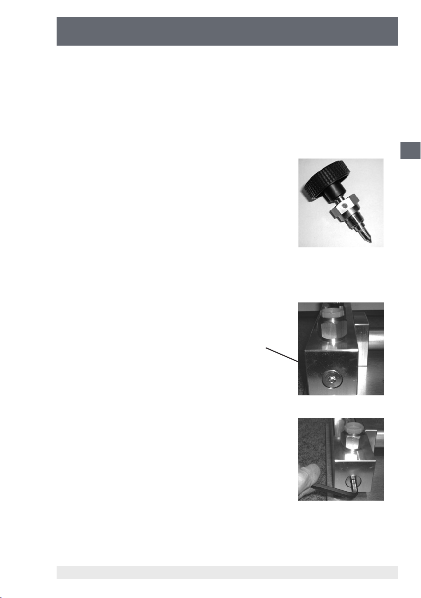
Bomba manual de husillo
CPP1000-M/-L
Las siguientes herramientas son necesarias para la instalación:
■
Llave de barra hexagonal 8 mm
■
Llave de boca de 27 mm e/c.
■
Pinza
Por favor controlar el volumen de suministro:
■
1 válvula con obturaciones integrada
Vista lateral de la bomba manual de husillo con vista al tapón obturador con hexágono interior:
Tapón obturador con
hexágono interior
Soltar el tapón obturador con una llave de barra
hexagonal de 8 mm y desenroscarlo.
E
11178035 12/2010 GB/D/F/E
WIKA Manual de instrucciones Bomba manual de husillo 77
Page 78

Bomba manual de husillo
CPP1000-M/-L
Después de desenroscar el tapón obturador, un
cuerpo pequeño, rojo y cilíndrico de plástico es
visible en el interior.
Se trata de una pieza para reducir el volumen
(reduce el volumen en el interior de la bomba
con la válvula de cierre o de regulación na no
instalada).
E
Sacar la pieza de plástico con una pinza o soplarla con aire comprimido por la conexión de prueba
abierta.
Enroscar la válvula de cierre o de regulación na
en la bomba manual de husillo.
Apretar bien la válvula utilizando una llave de
boca de 27 mm.
Estas piezas sobran y pueden ser eliminados:
■
Tapón obturador
■
Cuerpo rojo cilíndrico
WIKA Manual de instrucciones Bomba manual de husillo78
11178035 12/2010 GB/D/F/E
Page 79

Bomba manual de husillo
CPP1000-M/-L
7. Datos técnicos
CPP1000-M CPP1000-L
Campo de presión bar 0 ... 1000
Medio
Tomas de presión 2 x G ½ rosca hembra, libre, con junta tórica+
Distancia conexiones de prueba mm 200 115
Recipiente para líquidos cm³ 110 55
Diámetro del pistón mm 8
Volumen de inyección por vuelta cm³ aprox. 0,1
Volumen de inyección total cm³ aprox. 3,9
Ajuste de precisión de la presión Opción, véanse accesorios
Energía empleada
- 250 bares Nm 2,0
- 500 bares Nm 4,0
- 1000 bares Nm 8,0
Material
- Pistón Acero al cromo-níquel
- Cilindro Latón
- Brida trasera Aluminio
- Juntas FKM y NBR; opcional EPDM
Fijación estacionaria Dos oricios en la brida delantera Ø 6,4 mm
Dimensiones mm
Peso kg 6,3 5,6
1) Otros medios de transmisión de presión a solicitud.
Líquidos hidráulicos a base de aceite mineral Agua limpia y libre de cal
Válvula de regulación na en el lado
420 (long.) x 280 (anch.) x 103 (alt.) 420 (long.) x 240 (anch.) x 103 (alt.)
1)
E
11178035 12/2010 GB/D/F/E
WIKA Manual de instrucciones Bomba manual de husillo 79
Page 80

Bomba manual de husillo
CPP1000-M/-L
8. Dimensiones
E
ca. Ø 354
33,5
418
306
64
2 x Ø 6.4
223
ca. 108
71
73
280
200
195
78
115
45
CPP1000-MCPP1000-L
11178035 12/2010 GB/D/F/E
WIKA Manual de instrucciones Bomba manual de husillo80
Page 81

Bomba manual de husillo
CPP1000-M/-L
9. Datos de pedido / Accesorios
Accesorios N° de pedido
Bomba manual de husillo CPP1000-M 12401447
Bomba manual de husillo CPP1000-L, versión portable incl. válvu-
la de regulación na y tapa de depósito hermetizada
Aceite especial para la serie de bombas de prueba CPP1000 y
CPP1600 en botella de plástico, contenido 1 litro
Válvula de cierre para la conexión de prueba directamente en
la bomba manual de husillo para llenar los aparatos de gran
volumen fácilmente con el medio. Presión admisible: máx. 1000
bares
Para probetas e instrumentos de referencia se recomiendan 2
válvulas de cierre.
La válvula de regulación na que puede instalarse posteriormente
en la CPP1000-M permite aproximarse exactamente a los puntos
de medición
Tapón obturador con rosca macho G ½, material: latón 11155230
Juego de juntas tóricas consiste en 10 juntas de recambio para
las conexiones de prueba, material: FKM/FPM
Adaptador de rosca con rosca macho G ½ en rosca hembra G ⅛,
material: latón
Adaptador de rosca con rosca macho G ½ en rosca hembra G ¼,
material: latón
Adaptador de rosca con rosca macho G ½ en rosca hembra G ⅜,
material: latón
Adaptador de rosca con rosca macho G ½ en rosca hembra M20
x 1,5, material: latón
Adaptador de rosca con rosca macho G ½ en rosca hembra ¼
NPT, material: latón
Adaptador de rosca con rosca macho G ½ en rosca hembra ½
NPT, material: latón
Pieza de conexión angular de 90° para probetas con conexión
trasera
12677133
2099882
11208384
11248351
12422487
9090207
9090231
9090266
9090355
0187119
0187143
1564838
E
11178035 12/2010 GB/D/F/E
WIKA Manual de instrucciones Bomba manual de husillo 81
Page 82

Bomba manual de husillo
CPP1000-M/-L
E
11178035 12/2010 GB/D/F/E
WIKA Manual de instrucciones Bomba manual de husillo82
Page 83

WIKA Global
Europe
Austria
WIKA Messgerätevertrieb
Ursula Wiegand GmbH & Co. KG
1230 Vienna
Tel. (+43) 1 86916-31
Fax: (+43) 1 86916-34
E-Mail: info@wika.at
www.wika.at
Benelux
WIKA Benelux
6101 WX Echt
Tel. (+31) 475 535-500
Fax: (+31) 475 535-446
E-Mail: info@wika.nl
www.wika.nl
Bulgaria
WIKA Bulgaria EOOD
Bul. „Al. Stamboliiski“ 205
1309 Soa
Tel. (+359) 2 82138-10
Fax: (+359) 2 82138-13
E-Mail: t.antonov@wika.bg
Croatia
WIKA Croatia d.o.o.
Hrastovicka 19
10250 Zagreb-Lucko
Tel. (+385) 1 6531034
Fax: (+385) 1 6531357
E-Mail: info@wika.hr
www.wika.hr
Finland
WIKA Finland Oy
00210 Helsinki
Tel. (+358) 9-682 49 20
Fax: (+358) 9-682 49 270
E-Mail: info@wika.
www.wika.
France
WIKA Instruments s.a.r.l.
95610 Eragny-sur-Oise
Tel. (+33) 1 343084-84
Fax: (+33) 1 343084-94
E-Mail: info@wika.fr
www.wika.fr
Italy
WIKA Italia Srl & C. Sas
20020 Arese (Milano)
Tel. (+39) 02 9386-11
Fax: (+39) 02 9386-174
E-Mail: info@wika.it
www.wika.it
Poland
WIKA Polska S.A.
87-800 Wloclawek
Tel. (+48) 542 3011-00
Fax: (+48) 542 3011-01
E-Mail: info@wikapolska.pl
www.wikapolska.pl
11178035 12/2010 GB/D/F/E
Romania
WIKA Instruments Romania S.R.L.
Bucuresti, Sector 5
Calea Rahovei Nr. 266-268
Corp 61, Etaj 1
78202 Bucharest
Tel. (+40) 21 4048327
Fax: (+40) 21 4563137
E-Mail: m.anghel@wika.ro
Russia
ZAO WIKA MERA
127015 Moscow
Tel. (+7) 495-648 01 80
Fax: (+7) 495-648 01 81
E-Mail: info@wika.ru
www.wika.ru
Serbia
WIKA Merna Tehnika d.o.o.
Sime Solaje 15
11060 Belgrade
Tel. (+381) 11 2763722
Fax: (+381) 11 753674
E-Mail: info@wika.co.yu
www.wika.co.yu
Spain
Instrumentos WIKA, S.A.
C/Josep Carner, 11-17
08205 Sabadell (Barcelona)
Tel. (+34) 933 938630
Fax: (+34) 933 938666
E-Mail: info@wika.es
www.wika.es
Switzerland
Manometer AG
6285 Hitzkirch
Tel. (+41) 41 91972-72
Fax: (+41) 41 91972-73
E-Mail: info@manometer.ch
www.manometer.ch
Turkey
WIKA Instruments Istanbul
Basinc ve Sicaklik Ölcme Cihazlari
Ith. Ihr. ve Tic. Ltd. Sti.
Bayraktar Bulvari No. 21
34775 Yukari Dudullu - Istanbul
Tel. (+90) 216 41590-66
Fax: (+90) 216 41590-97
E-Mail: info@wika.com.tr
www.wika.com.tr
Ukraine
WIKA Pribor GmbH
83016 Donetsk
Tel. (+38) 062 34534-16
Fax: (+38) 062 34534-17
E-Mail: info@wika.ua
www.wika.ua
United Kingdom
WIKA Instruments Ltd
Merstham, Redhill RH13LG
Tel. (+44) 1737 644-008
Fax: (+44) 1737 644-403
E-Mail: info@wika.co.uk
www.wika.co.uk
North America
Canada
WIKA Instruments Ltd.
Head Oce
Edmonton, Alberta, T6N 1C8
Tel. (+1) 780 46370-35
Fax: (+1) 780 46200-17
E-Mail: info@wika.ca
www.wika.ca
Mexico
Instrumentos WIKA Mexico S.A. de C.V.
01210 Mexico D.F.
Tel. (+52) 55 55466329
E-Mail: ventas@wika.com
www.wika.com.mx
USA
WIKA Instrument Corporation
Lawrenceville, GA 30043
Tel. (+1) 770 5138200
Fax: (+1) 770 3385118
E-Mail: info@wika.com
www.wika.com
WIKA Instrument Corporation
Houston Facility
950 Hall Court
Deer Park, TX 77536
Tel. (+1) 713-475 0022
Fax (+1) 713-475 0011
E-mail: info@wikahouston.com
www.wika.com
Mensor Corporation
201 Barnes Drive
San Marcos, TX 78666
Tel. (+1) 512 3964200-15
Fax (+1) 512 3961820
E-Mail: sales@mensor.com
www.mensor.com
South America
Argentina
WIKA Argentina S.A.
Buenos Aires
Tel. (+54) 11 47301800
Fax: (+54) 11 47610050
E-Mail: info@wika.com.ar
www.wika.com.ar
Brazil
WIKA do Brasil Ind. e Com. Ltda.
CEP 18560-000 Iperó - SP
Tel. (+55) 15 34599700
Fax: (+55) 15 32661650
E-Mail: marketing@wika.com.br
www.wika.com.br
83
Page 84

WIKA Global
Chile
WIKA Chile S.P.A.
Av. Coronel Pereira, 101
Ocina 101
Las Condes
Santiago de Chile
Tel. (+56) 9 66084258
Fax (+56) 2 3346219
E-Mail: info@wika.cl
www.wika.cl
Asia
China
WIKA Shanghai Oce
A2615, NO.100, Zuyi Road
Changning District
200051 Shanghai
Tel. (+86) 21 538525-72
Fax: (+86) 21 538525-75
E-Mail: info@wika.com.cn
www. wika.com.cn
India
WIKA Instruments India Pvt. Ltd.
Village Kesnand, Wagholi
Pune - 412 207
Tel. (+91) 20 66293-200
Fax: (+91) 20 66293-325
E-Mail: sales@wika.co.in
www.wika.co.in
Japan
WIKA Japan K. K.
Tokyo 105-0023
Tel. (+81) 3 543966-73
Fax: (+81) 3 543966-74
E-Mail: info@wika.co.jp
Kazakhstan
WIKA Kazakhstan LLP
169, Rayimbek avenue
050050 Almaty, Kazakhstan
Tel. (+7) 32 72330848
Fax: (+7) 32 72789905
E-Mail: info@wika.kz
www.wika.kz
Korea
WIKA Korea Ltd.
#569-21 Gasan-dong
Seoul 153-771 Korea
Tel. (+82) 2 869 05 05
Fax (+82) 2 869 05 25
E-Mail: info@wika.co.kr
www.wika.co.kr
Malaysia
WIKA Instrumentation (M) Sdn. Bhd.
47100 Puchong, Selangor
Tel. (+60) 3 80 63 10 80
Fax: (+60) 3 80 63 10 70
E-Mail: info@wika.com.my
www.wika.com.my
Singapore
WIKA Instrumentation Pte. Ltd.
569625 Singapore
Tel. (+65) 68 44 55 06
Fax: (+65) 68 44 55 07
E-Mail: info@wika.com.sg
www.wika.com.sg
Taiwan
WIKA Instrumentation Taiwan Ltd.
Pinjen, Taoyuan
Tel. (+886) 3 420 6052
Fax: (+886) 3 490 0080
E-Mail: info@wika.com.tw
www.wika.com.tw
Africa / Middle East
Egypt
WIKA Near East Ltd.
El-Serag City Towers
-Tower#2 - Oce#67-
Nasr City Cairo
Tel. (+20) 2 22733140
Fax: (+20) 2 22703815
E-Mail: wika.repcairo@wika.de
www.wika.com.eg
Namibia
WIKA Instruments Namibia (Pty) Ltd.
P.O. Box 31263
Pionierspark
Windhoek
Tel. (+26) 4 6123 8811
Fax (+26) 4 6123 3403
E-Mail: info@wika.com.na
www.wika.com.na
South Africa
WIKA Instruments (Pty.) Ltd.
Gardenview,
Johannesburg 2047
Tel. (+27) 11 62100-00
Fax: (+27) 11 62100-59
E-Mail: sales@wika.co.za
www.wika.co.za
United Arab Emirates
WIKA Middle East FZE
Jebel Ali, Dubai
Tel. (+971) 4 8839-090
Fax: (+971) 4 8839-198
E-Mail: wikame@emirates.net.ae
Australia
Australia
WIKA Australia Pty. Ltd.
Rydalmere, NSW 2116
Tel. (+61) 2 88455222
Fax: (+61) 2 96844767
E-Mail: sales@wika.com.au
www.wika.com.au
New Zealand
WIKA Instruments Limited
Unit 7 / 49 Sainsbury Road
St Lukes - Auckland 1025
Tel. (+64) 9 8479020
Fax: (+64) 9 8465964
E-Mail: info@wika.co.nz
www.wika.co.nz
84
WIKA Alexander Wiegand SE & Co. KG
Alexander-Wiegand-Straße 30
63911 Klingenberg
• Germany
Phone (+49) 93 72/132-9986
Fax (+49) 93 72/132-217
E-Mail testequip@wika.de
www.wika.de
11178035 12/2010 GB/D/F/E
 Loading...