

Page 1

Operating instructions
Betriebsanleitung
Portable pressure calibrator, model CPH7650
Tragbarer Druckkalibrator, Typ CPH7650
EN
DE
Portable pressure calibrator, model CPH7650
Page 2

EN
Operating instructions model CPH7650 Page 3 - 58
DE
Betriebsanleitung Typ CPH7650 Seite 59 - 113
Further languages can be found at www.wika.com.
© 03/2018 WIKA Alexander Wiegand SE & Co. KG
All rights reserved. / Alle Rechte vorbehalten.
®
WIKA
is a registered trademark in various countries.
®
WIKA
ist eine geschützte Marke in verschiedenen Ländern.
Prior to starting any work, read the operating instructions!
Keep for later use!
Vor Beginn aller Arbeiten Betriebsanleitung lesen!
Zum späteren Gebrauch aufbewahren!
2
WIKA operating instructions, model CPH7650
14261987.01 03/2018 EN/DE
Page 3

Contents
Contents
1. General information 5
2. Safety 6
2.1 Intended use . . . . . . . . . . . . . . . . . . . . . . 7
2.2 Personnel qualification . . . . . . . . . . . . . . . . . . . 8
2.3 Special hazards . . . . . . . . . . . . . . . . . . . . . 8
2.4 Use of Lithium-Ion rechargeable batteries . . . . . . . . . . . .10
2.5 Labelling, safety marks . . . . . . . . . . . . . . . . . . .12
3. Specifications 13
4. Design and function 15
4.1 Description . . . . . . . . . . . . . . . . . . . . . . . 15
4.2 Front . . . . . . . . . . . . . . . . . . . . . . . . .16
4.3 Scope of delivery . . . . . . . . . . . . . . . . . . . . .17
4.4 Voltage supply . . . . . . . . . . . . . . . . . . . . . .17
4.5 User interface . . . . . . . . . . . . . . . . . . . . . . 18
4.5.1 Requirements for test assemblies with the CPH7650 . . . . . . . 19
4.5.2 Important instrument settings for calibration using calibration mode . . 19
4.5.3 Zero point setting and offset correction . . . . . . . . . . . .20
4.5.4 Reference pressure sensor CPT6000 . . . . . . . . . . . . 20
5. Transport, packaging and storage 22
5.1 Transport. . . . . . . . . . . . . . . . . . . . . . . . 22
5.2 Packaging . . . . . . . . . . . . . . . . . . . . . . . 22
5.3 Storage . . . . . . . . . . . . . . . . . . . . . . . . 22
6. Commissioning, operation 23
6.1 Menu structure (operating modes) . . . . . . . . . . . . . . . 24
6.2 Explanation of the display . . . . . . . . . . . . . . . . . . 25
6.2.1 Instrument status messages shortly after switching on the CPH7650 . .25
6.2.2 Switching the pressure calibrator off . . . . . . . . . . . . .26
6.2.3 Display contents of the operating modes . . . . . . . . . . . 26
6.2.4 Content of the SETUP menu . . . . . . . . . . . . . . .29
6.3 Operating modes . . . . . . . . . . . . . . . . . . . . .32
6.3.1 MEASURING mode . . . . . . . . . . . . . . . . . . 32
6.3.2 MEASURING mode (with test item) . . . . . . . . . . . . . 34
6.3.3 Mode CALIBRATION . . . . . . . . . . . . . . . . . . 36
6.3.4 CALIBRATION mode (preparing the test points of a calibration). . . . 38
6.3.5 CALIBRATION mode (calibration of a pressure transmitter) . . . . . 41
6.3.6 CALIBRATION mode (calibration of a pressure gauge) . . . . . . 42
6.3.7 SWITCH TEST mode . . . . . . . . . . . . . . . . . . 43
6.4 SETUP additional menu items . . . . . . . . . . . . . . . . 45
14261987.01 03/2018 EN/DE
EN
3WIKA operating instructions, model CPH7650
Page 4

Contents
6.4.1 SETUP additional menu items: Functions . . . . . . . . . . . 45
6.4.2 SETUP additional menu items: CPH info . . . . . . . . . . . 46
6.4.3 SETUP additional menu items: Reference sensor . . . . . . . . 47
EN
6.4.4 SETUP additional menu items: Reference sensor list . . . . . . . 48
6.4.5 SETUP additional menu items: CPH configuration . . . . . . . .49
6.4.6 SETUP additional menu items: Interface . . . . . . . . . . . 50
6.4.7 SETUP additional menu items: CLEAR CalProg . . . . . . . . .50
6.5 Connection of the model CPT6000 reference pressure sensor . . . . . 51
6.6 Voltage supply . . . . . . . . . . . . . . . . . . . . . .51
6.7 Charging/discharging the Lithium-Ion rechargeable batteries . . . . . .52
6.8 Pressure measurement . . . . . . . . . . . . . . . . . . .53
6.9 Measuring and sourcing current (4 ... 20 mA) . . . . . . . . . . . 53
7. Maintenance, cleaning and recalibration 54
7.1 Maintenance . . . . . . . . . . . . . . . . . . . . . . 54
7.2 Cleaning . . . . . . . . . . . . . . . . . . . . . . . .54
7.3 Recalibration . . . . . . . . . . . . . . . . . . . . . .54
8. Faults 55
9. Dismounting, return and disposal 56
9.1 Dismounting . . . . . . . . . . . . . . . . . . . . . . 56
9.2 Return. . . . . . . . . . . . . . . . . . . . . . . . . 56
9.3 Disposal . . . . . . . . . . . . . . . . . . . . . . . .56
10. Accessories 57
Declarations of conformity can be found online at www.wika.com.
4 WIKA operating instructions, model CPH7650
14261987.01 03/2018 EN/DE
Page 5

1. General information
1. General information
■
The portable pressure calibrator described in the operating instructions has been
manufactured using state-of-the-art technology. All components are subject to
stringent quality and environmental criteria during production. Our management
systems are certified to ISO 9001 and ISO 14001.
■
These operating instructions contain important information on handling the instrument.
Working safely requires that all safety instructions and work instructions are observed.
■
Observe the relevant local accident prevention regulations and general safety
regulations for the instrument's range of use.
■
The operating instructions are part of the product and must be kept in the immediate
vicinity of the instrument and readily accessible to skilled personnel at any time.
■
Skilled personnel must have carefully read and understood the operating instructions
prior to beginning any work.
■
The manufacturer's liability is void in the case of any damage caused by using the
product contrary to its intended use, non-compliance with these operating instructions,
assignment of insufficiently qualified skilled personnel or unauthorised modifications to
the instrument.
EN
■
The general terms and conditions contained in the sales documentation shall apply.
■
Subject to technical modifications.
■
Factory calibrations / DKD/DAkkS calibrations are carried out in accordance with
international standards.
■
Further information:
- Internet address: www.wika.de / www.wika.com
- Relevant data sheet: CT 17.02
- Application consultant:
Tel.: +49 9372 132-9986
Fax: +49 9372 132-8767
info@wika.com
14261987.01 03/2018 EN/DE
5WIKA operating instructions, model CPH7650
Page 6
1. General information / 2. Safety
Explanation of symbols
WARNING!
EN
... indicates a potentially dangerous situation that can result in serious injury
or death, if not avoided.
CAUTION!
... indicates a potentially dangerous situation that can result in light injuries
or damage to property or the environment, if not avoided.
Information
... points out useful tips, recommendations and information for efficient and
trouble-free operation.
DANGER!
... identifies hazards caused by electrical power. Should the safety
instructions not be observed, there is a risk of serious or fatal injury.
2. Safety
WARNING!
Before installation, commissioning and operation, ensure that the
appropriate reference pressure sensor has been selected in terms of
measuring range, design and specific measuring conditions.
Non-observance can result in serious injury and/or damage to the
equipment.
Further important safety instructions can be found in the individual chapters
of these operating instructions.
6 WIKA operating instructions, model CPH7650
14261987.01 03/2018 EN/DE
Page 7

2. Safety
2.1 Intended use
This portable pressure calibrator serves as a calibration instrument for the widest variety
of pressure measuring instruments and has been designed for mobile use as well as for
stationary workshop and laboratory testing. Through the combination of the integrated
electrical pump and the electrical modules, in addition to the traditional measurement of
current and voltage signals it also enables you to supply transmitters or sensors with a
max. of 30 mA (voltage (idling) = DC 24 V). The pressure calibrator can be used to carry
out and document a complete calibration process.
WARNING!
■
Only use model CPT6000 reference pressure sensors!
■
Using other sensors could damage both the pressure calibrator and the
reference pressure sensor.
■
To change the sensor, switch off the pressure calibrator and make sure
the system is vented. Before switching the instrument on, connect the
sensor, otherwise it may not be correctly identified by the instrument.
■
When the CPH7650 is switched on, the CPT6000 reference pressure
sensor must not be under pressure, but rather should be at atmospheric
pressure. For overpressure or gauge pressure sensors, there is a
pressure compensation vent in the top of the sensor under the plastic
fitting. This vent (with integrated diaphragm) must always remain clear!
The instrument has been designed and built solely for the intended use described here,
and may only be used accordingly.
EN
The technical specifications contained in these operating instructions must be observed.
Improper handling or operation of the instrument outside of its technical specifications
requires the instrument to be taken out of service immediately and inspected by an
authorised WIKA service engineer.
Handle electronic precision measuring instruments with the required care (protect from
humidity, impacts, strong magnetic fields, static electricity and extreme temperatures,
do not insert any objects into the instrument or its openings). Plugs and sockets must be
protected from contamination.
If the instrument is transported from a cold into a warm environment, the formation of
condensation may result in instrument malfunction. Before putting it back into operation,
wait for the instrument temperature and the room temperature to equalise.
The manufacturer shall not be liable for claims of any type based on operation contrary to
the intended use.
14261987.01 03/2018 EN/DE
7WIKA operating instructions, model CPH7650
Page 8
2. Safety
2.2 Personnel qualification
WARNING!
EN
Skilled personnel
Skilled personnel are understood to be personnel who, based on their technical training,
knowledge of measurement and control technology and on their experience and
knowledge of country-specific regulations, current standards and directives, are capable
of carrying out the work described and independently recognising potential hazards.
Special operating conditions require further appropriate knowledge, e.g. of aggressive
media.
2.3 Special hazards
Risk of injury should qualification be insufficient!
Improper handling can result in considerable injury and damage to
equipment.
The activities described in these operating instructions may only be carried
out by skilled personnel who have the qualifications described below.
WARNING!
■
Do not apply a voltage greater than the specified voltage to the
instrument (see chapter 3 „Specifications“).
■
Do not apply any external pressure to the CPH7650.
■
Make sure that the test probes never contact a voltage source while the
test cables are connected to the current terminals.
■
Do not use the calibrator if it is damaged. Before using the instrument,
check that there are no cracks on the case or any missing plastic parts.
Pay particular attention to the insulation of the connectors.
■
Select the proper function and correct measuring range for the
measurement.
■
Observe the operating parameters in accordance with chapter
3 “Specifications”.
■
Always operate the pressure calibrator within the defined pressure range.
■
To ensure problem-free operation, only operate the instrument on battery
power. Only use the power supply unit for charging the instrument's
batteries.
■
Inspect the test cables for damaged insulation or exposed metal. Check
the continuity of the leads. Damaged test leads should be replaced before
using the instrument.
■
When using test probes, keep fingers away from the test probe contacts.
Keep your fingers behind the test probes' finger guards.
■
First connect the common lead, and then the live lead. When
disconnecting, remove the live test lead first.
14261987.01 03/2018 EN/DE
8 WIKA operating instructions, model CPH7650
Page 9

2. Safety
■
Do not use the instrument if it is not working properly. The instrument
protection might be compromised. If in doubt, have the instrument
checked.
■
Do not operate the instrument in areas with explosive gases, vapours or
dust.
■
When measuring pressure, make sure that the pressure calibrator has
been switched to a depressurised state before the reference sensor or
the test item is connected or disconnected.
■
Disconnect test leads before changing to another measurement or source
function.
■
The switching valve (+/- pressure) should only ever be actuated when in a
depressurised state.
WARNING!
■
To avoid false indications, which could lead to possible electric shock or
injuries, charge the rechargeable battery as soon as the battery indicator
appears.
■
In order to avoid any possible damage to the instrument or the test
equipment, use the correct leads, the correct function and the correct
range for the measuring application.
DANGER!
Danger to life caused by electric current
Upon contact with live parts, there is a direct danger to life.
■
Charging using a defective power supply unit (e.g. short circuit from the
mains voltage to the output voltage) can result in life-threatening voltages
at the instrument!
■
Only use the power supply unit permitted by WIKA for the model
CPH7650 portable pressure calibrator.
■
Only use a charger that is fully functional or undamaged.
EN
The safety of the operator may be endangered if, for example
■
there is visible damage to the instrument.
■
the instrument is no longer working as specified.
■
the instrument has been stored under unsuitable conditions for an extended period of
time.
If there is any doubt, please return the instrument to the manufacturer for repair or
maintenance.
14261987.01 03/2018 EN/DE
9WIKA operating instructions, model CPH7650
Page 10

2. Safety
2.4 Use of Lithium-Ion rechargeable batteries
WARNING!
EN
Misusing Lithium-Ion batteries can lead to heating, explosion or ignition and
result in serious injury. Follow the safety instructions listed below:
■
Do not solder directly to the Lithium-Ion batteries.
■
Do not incinerate or heat the Lithium-Ion batteries.
■
The Lithium-Ion batteries must only ever be connected with the correct
polarity.
■
Never connect the positive terminal and the negative terminal of the
Lithium-Ion batteries to each other with any metallic object (such as wire).
■
Never carry or store the Lithium-Ion batteries together with necklaces,
hairpins, or other metal objects.
WARNING!
■
Lithium-Ion batteries should never be punctured with nails nor hit with a
hammer. In addition, Lithium-Ion batteries must never be trodden on or
exposed to other strong shocks or vibrations.
■
Lithium-Ion batteries must never come into contact with water or salt
water. Moreover, they must never get wet.
WARNING!
Never take the Lithium-Ion battery apart nor alter it in any way. It contains
safety and protection devices which, if damaged, may cause it to generate
heat, explode or ignite.
WARNING!
Never place the Lithium-Ion batteries close to fires, ovens or other
high-temperature locations. Never leave the Lithium-Ion batteries in direct
sunshine or use or store them inside cars in hot weather. Doing so may
cause the Lithium-Ion batteries to generate heat, explode or ignite. Using the
Lithium-Ion batteries in this manner may also result in a loss of performance
and a shortened service life.
Never fit the Lithium-Ion batteries into equipment designed to be
hermetically sealed. In some cases hydrogen or oxygen may be discharged
from the Lithium-Ion batteries, which may result in rupture, fire or explosion.
10 WIKA operating instructions, model CPH7650
14261987.01 03/2018 EN/DE
Page 11

2. Safety
WARNING!
The Lithium-Ion batteries must, without fail, no longer be used if, during
operation, charging or storing they give off an unusual smell, feel hot,
change colour, change shape, or appear abnormal in any other way. Contact
your sales partner if any of these problems are observed.
Never put the Lithium-Ion batteries in microwave ovens, high-pressure
containers nor on induction cookers.
Should the Lithium-Ion batteries ever leak and the fluid come into contact
with the eyes, do not under any circumstances rub the eyes. Rinse the eyes
thoroughly with water and seek immediate medical attention. If the eyes are
left untreated, damage to the eyes could occur.
CAUTION!
When the Lithium-Ion batteries wear out, insulate the terminals with
adhesive tape or similar materials before disposal.
WARNING!
Follow the instructions listed below for charging the Lithium-Ion batteries.
Failure to do so may cause the Lithium-Ion batteries to become hot, explode
or ignite and result in serious injury.
■
To charge the Lithium-Ion batteries, only ever use the specified WIKA
battery charger.
■
Never connect the Lithium-Ion batteries directly to a mains plug or to a
car's cigarette lighter.
■
Never leave the Lithium-Ion batteries in or near fire, nor in direct sunlight.
If the Lithium-Ion batteries become hot, the built-in safety device is
activated and overcharging prevented. Heating the Lithium-Ion batteries
can damage the safety device and can thus lead them to heat up further,
to cease to work or to ignite.
EN
WARNING!
Never continue to charge the Lithium-Ion batteries if they do not fully
recharge within the specified time. Doing so may cause the Lithium-Ion
batteries to become hot, explode or ignite.
14261987.01 03/2018 EN/DE
11WIKA operating instructions, model CPH7650
Page 12
2. Safety
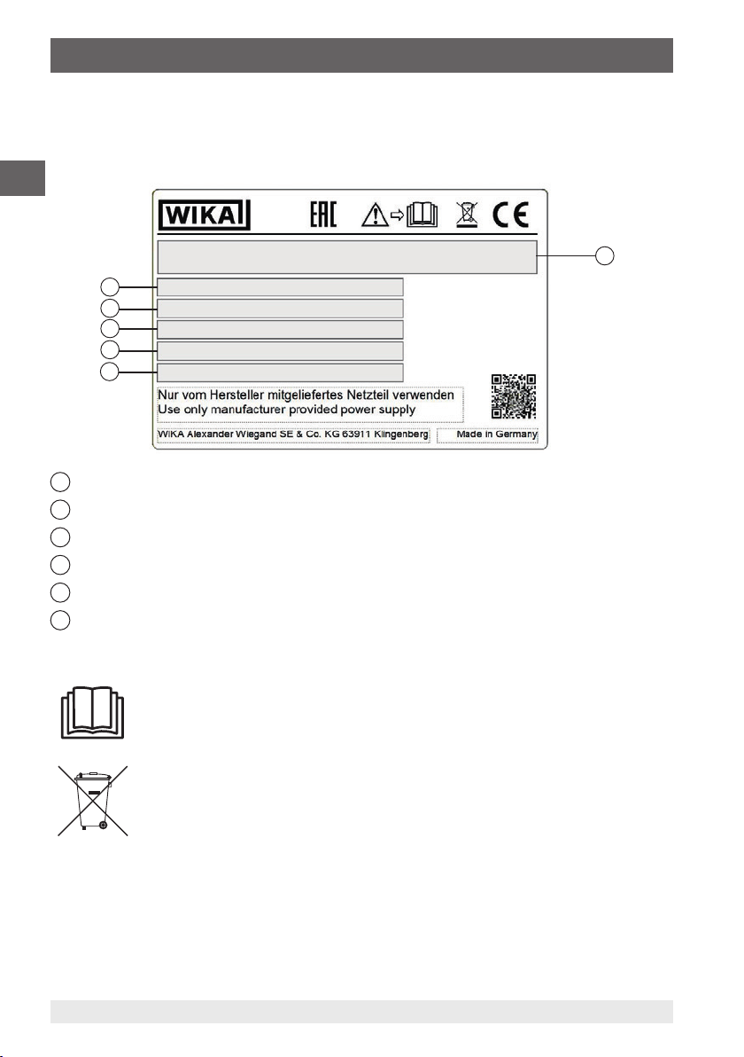
2.5 Labelling, safety marks
Product label
EN
6
5
4
3
2
1
Product name
2
Date of manufacture (month/year)
3
Serial number
4
Output signal, power supply
5
Input signal
6
Pressure range
1
Symbols
Before mounting and commissioning the instrument, ensure you read the
operating instructions!
This marking on the instruments indicates that they must not be disposed of
in domestic waste. The disposal is carried out by return to the manufacturer
or by the corresponding municipal authorities.
12 WIKA operating instructions, model CPH7650
14261987.01 03/2018 EN/DE
Page 13

3. Specifications
3. Specifications
Measuring ranges
Pressure
Gauge pressure -1 … +20 bar, -1 … +10 bar, 0 … 20 bar, 0 … 10 bar
Absolute pressure 0 … 10 bar abs., 0 … 20 bar abs.
Overpressure limit
Accuracy 0.025 % FS
Resolution 5-digit
Temperature compensation 15 … 35 °C (59 ... 95 °F)
Temperature coefficient 0.002 % of span/°C outside of 15 ... 35 °C (59 ... 95 °F)
Current
Measuring range 0 … 24 mA (max. load 1,000 Ω)
Resolution 1 µA
Accuracy 0.015 % of reading ±2 µA (simulation and measurement)
Voltage
Measuring range DC 0 … 30 V
Resolution 1 mV
Accuracy 0.015 % of reading ±2 mV (measurement)
1) Via exchangeable model CPT6000 reference pressure sensors
2) The electrical pump can generate -0.85 … +20 bar (-12 … 290 psi).
1)
2)
3 times
EN
Base instrument
Pressure supply -0.85 ... +20 bar (-12 ... +290 psi), via integrated electric pump
Pressure connection for test
item
Permissible media For dry, clean and non-aggressive gases
Output
Voltage supply DC 24 V
Power supply
Battery type Lithium-Ion rechargeable battery
Permissible ambient conditions
Operating temperature -10 … +50 °C (14 ... 122 °F)
Storage temperature -20 … +60 °C (-4 ... +140 °F)
Relative humidity 35 ... 85 % r. h. (non-condensing)
Communication
Interface USB via special interface cable
14261987.01 03/2018 EN/DE
G ½" female thread
13WIKA operating instructions, model CPH7650
Page 14

3. Specifications
Base instrument
Case
EN
Case NK-7TM resin
Front panel Aluminium
Ingress protection IP67 (case closed)
IP40 (case opened)
Dimensions 387.4 x 304.8 x 177.8 mm (15.25 x 12 x 7 in)
Weight approx. 7 kg (15.5 lbs.)
Certificates
Certificate
Calibration Standard: 3.1 calibration certificate per DIN EN 10204
Option: DKD/DAkkS calibration certificate
Recommended recalibration
1 year (dependent on conditions of use)
interval
Approvals and certificates, see website
Available pressure range and resolution
Pressure range and factors
Gauge pressure -1 ... +20 bar (-14.5 ... +290 psi)
Overpressure limit 40 bar (580 psi)
Unit Conversion factor
psi 1 300.00
bar 0.06894757 20.684
mbar 68.94757 20,684
kPa 6.894757 2,068.4
MPa 0.00689476 2.0684
kg/cm² 0.07030697 21.092
O (4 °C) 70.3089 21,093
cmH
2
O (20 °C) 70.4336 21,130
cmH
2
O (4 °C) 27.68067 8,304.2
inH
2
O (20 °C) 27.72977 8,318.9
inH
2
O (60 °F) 27.70759 8,312.3
inH
2
mmHg (0 °C) 51.71508 15,515
inHg (0 °C) 2.03602 610.81
3) Electrical pump: -0.85 … +20 bar (-12 … 290 psi)
14261987.01 03/2018 EN/DE
14 WIKA operating instructions, model CPH7650
Page 15
3. Specifications / 4. Design and function
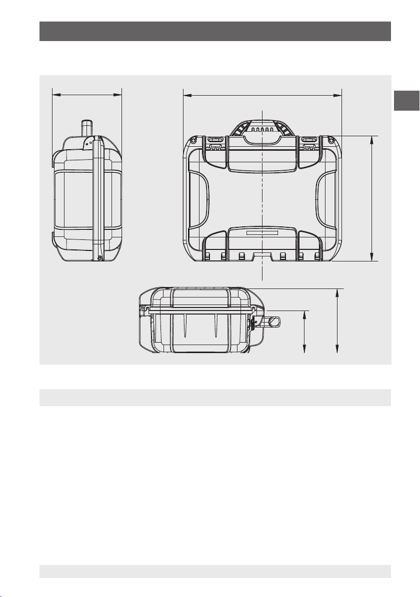
104 (4,11)
158 (6,22)
Dimensions in mm (in)
172 (6,76)
390 (15,36)
EN
308 (12,13)
4. Design and function
4.1 Description
The CPH7650 is a compact, portable pressure calibrator, which has been designed
for mobile use as well as for stationary workshop and laboratory testing. An integrated
electrical pump enables you to generate pressures up to 20 bar (300 psi) and an
integrated electrical module also enables you to supply transmitters or sensors with
a current of max. 30 mA (voltage (idling) = DC 24 V), in addition to the traditional
measurement of current and voltage signals.
The pressure calibrator can be used to carry out and document a complete calibration
process. In addition to the features of displaying or measuring and calibration, there
is also a switch test. The use of the WIKA-Cal software also allows a complete
documentation.
14261987.01 03/2018 EN/DE
15WIKA operating instructions, model CPH7650
Page 16

4. Design and function
4.2 Front
EN
1
Test item
2
Overview of the electrical connection
1
2
3 4
5
6
7
8
9
10111213
3
Electrical connection to the model CPT6000 reference sensor
4
Reference sensor CPT6000
5
Connecion of the power supply unit
6
WIKA-Cal connection
7
Fine adjustment / drain valve
8
Switch for pressure / vacuum
9
Pump speed controller
10
Operation
11
Electrical module
12
Display
13
Numeric keypad
16 WIKA operating instructions, model CPH7650
14261987.01 03/2018 EN/DE
Page 17

4. Design and function
4.3 Scope of delivery
■
Portable pressure calibrator model CPH7650
■
Operating instructions
■
Test cables
■
Battery charger
■
3.1 calibration certificate per DIN EN 10204
Cross-check scope of delivery with delivery note.
4.4 Voltage supply
Charging the battery
In order to avoid false measurements, charge the battery as soon as the battery indicator
is displayed. If the battery has run down too far, the instrument will switch itself off
automatically.
Only ever use the power supply unit permitted by WIKA for the model CPH7650 portable
pressure calibrator.
To avoid measurement uncertainties, only use the CPH7650 without the mains supply
connected. The full pump performance can only be guaranteed with the battery fully
charged and without the power supply unit connected.
The instrument should be fully charged before being put into operation.
The battery capacity status (charge state in %) is displayed shortly after the instrument is
switched on. When the power supply unit is connected, the rechargeable battery will be
charged, even if the CPH7650 is switched off.
EN
The typical charging time of the rechargeable battery is < 5 hours.
WARNING!
■
When the power supply unit is no longer being used, the mains plug
should be disconnected from the mains socket. Do not leave the
rechargeable battery connected to the power supply unit for longer than
one day, since overcharging can shorten its service life.
■
Should the rechargeable battery still not be fully charged after 24 hours,
contact the manufacturer. When not being used, a fully charged battery
will lose its charge over time.
■
Extreme temperatures have an adverse effect on battery charging. As
a result, the battery may first need to be either cooled or warmed, as
appropriate.
■
When the battery is almost completely discharged, the message “low
BAT” appears in the display. To avoid a data loss, the instrument must be
charged immediately
14261987.01 03/2018 EN/DE
17WIKA operating instructions, model CPH7650
Page 18

4. Design and function
4.5 User interface
EN
6
5
1
SETUP menu
2
Selection and entry confirmation
3
Return to previous level
4
Clear entry
5
Input confirmation
6
Numeric keypad
Switch on via pressing any button
Switch off via menu item in main menu
1
2
3
4
18 WIKA operating instructions, model CPH7650
14261987.01 03/2018 EN/DE
Page 19

4. Design and function
4.5.1 Requirements for test assemblies with the CPH7650
■
Before starting any task, the instrument should be switched on briefly to determine
that there is sufficient charge in the battery (rechargeable battery capacity in %). The
battery capacity is indicated briefly in an instrument status message after switching
on (see chapter 6.2.1 “Instrument status messages shortly after switching on the
CPH7650”).
■
Initially, the test assembly must be physically assembled and, if necessary, connected
electrically (see chapter 4.5.4.1 “Connection of the model CPT6000 reference
pressure sensor”).
■
Before switching the CPH7650 on, ensure that the test assembly is not pressurised
(system is vented to atmosphere) and that the equipment is correctly assembled and
in the correct mounting position.
■
Only connect test and calibration installations once the system has been
depressurised!
Compensation for height differences
If a significant elevation difference exists between the CPT6000 reference pressure
sensor and the test item, then the pressure difference, based on a medium column, can
be compensated automatically via the menu (see chapter 6.4.5 “SETUP additional menu
items: CPH configuration”).
4.5.2 Important instrument settings for calibration using calibration mode
EN
Calibration date
The instrument has an integral real-time clock with date. The current date of a calibration
is stated later in the calibration certificate. Before starting a calibration, you must ensure
that the internal date of the CPH7650 is correct (see
chapter 6.4.5 “SETUP additional menu items: CPH configuration”).
Unit and resolution
After selecting one of the main menu items (e.g.: MEASURING, CALIBRATION or
SWITCH TEST) from the SETUP menu (press SETUP key), using the menu item “Unit”,
and its associated submenu respectively (move the cursor to “Unit” and press the right
or left arrow), you can set the unit and adjust its resolution (see chapter 6.3 “Operating
modes”).
14261987.01 03/2018 EN/DE
19WIKA operating instructions, model CPH7650
Page 20

4. Design and function
Available units, including their conversion factors in relation to the unit bar
bar 1.00000E+00
mbar 1.00000E-03
hPa 1.00000E-03
EN
psi 6.89475E-02
inHg (0 °C) 3.37690E-02
cmHG (0 °C) 1.33322E-02
MPa 1.00000E+01
kPa 1.00000E-02
Pa 1.00000E-05
O (4 °C) 9.80670E-02
mH
2
O (4 °C) 9.80670E-04
cmH
2
O (4 °C) 9.80670E-05
mmH
2
2
kg/cm
O (60 °C) 2.48800E-03
inH
2
O (0 °C) 1.33322E-03
mmH
2
4.5.3 Zero point setting and offset correction
Zero point setting for overpressure sensors
If the measured value shown on the CPH7650, with an overpressure sensor connected
and the test assembly vented to atmosphere, is not equal to zero, then by pressing the
CLEAR button twice (within five seconds), the zero point can be corrected (maximum
allowable correction value is twice the magnitude of the class accuracy).
9.80665E-01
Offset correction for absolute pressure sensors
For absolute pressure sensors, an offset correction can be made via the menu (see
chapter 6.4.3 “SETUP additional menu items: Reference sensor”).
4.5.4 Reference pressure sensor CPT6000
For the model CPH7650 pressure calibrator, there are many reference pressure sensors
to choose from, with accuracies of 0.025 % which can be interchanged quickly and
without tools. When the pressure calibrator is switched on, the reference pressure sensor
attached is recognised automatically, so that no further configuration of the sensor is
needed.
20 WIKA operating instructions, model CPH7650
14261987.01 03/2018 EN/DE
Page 21

4. Design and function
4.5.4.1 Connection of the model CPT6000 reference pressure sensor
WARNING!
■
Only use model CPT6000 reference pressure sensors!
■
Using other sensors could damage both the pressure calibrator and the
reference pressure sensor.
■
To change the sensor, switch off the pressure calibrator and make sure
the system is vented. Before switching the instrument on, connect the
sensor, otherwise it may not be correctly identified by the instrument.
■
When the CPH7650 is switched on, the CPT6000 reference pressure
sensor must not be under pressure, but rather should be at atmospheric
pressure. For overpressure or gauge pressure sensors, there is a
pressure compensation vent in the top of the sensor under the plastic
fitting. This vent (with integrated diaphragm) must always remain clear!
CAUTION!
Only ever use the original WIKA sensor connection cable in the operation of
CPT6000 reference pressure sensors.
WARNING!
The pump performance is independent of the pressure range of the selected
reference sensor. The operator must ensure that the CPT6000 reference
sensor is not over-pressured.
EN
4.5.4.2 Electrical connection of the CPT6000 reference pressure sensor to the
CPH7650
The calibrator and the reference pressure sensor are connected to each other electrically
using a separate connection cable. To electrically connect a model CPT6000 reference
pressure sensor, the corresponding cable connector must be plugged in at the sensor in
accordance with the orientation guide. To disconnect the sensor, do not pull on the cable,
but rather only on the connector sleeve.
To connect it to the CPH7650, the other end of the cable must also be plugged in in
accordance with the orientation guide.
4.5.4.3 Mechanical connection of the CPT6000 reference pressure sensor to the
CPH7650
To make the mechanical connection of the CPT6000 reference pressure sensor, it must
be placed, connection thread first, in the sensor bracket of the instrument. Then, the
sensor must be tightened again.
(Tighten = turn clockwise; release = turn anti-clockwise)
No further tools are required for this.
14261987.01 03/2018 EN/DE
21WIKA operating instructions, model CPH7650
Page 22

5. Transport, packaging, storage
5. Transport, packaging and storage
5.1 Transport
Check the portable pressure calibrator for any damage that may have been caused by
EN
transport. Obvious damage must be reported immediately.
5.2 Packaging
Do not remove packaging until just before mounting.
Keep the packaging as it will provide optimum protection during transport (e.g. change in
installation site, sending for repair).
5.3 Storage
Permissible conditions at the place of storage:
■
Storage temperature: -20 ... +60 °C
■
Relative humidity: 0 ... 85 % r. h. (non-condensing)
Avoid exposure to the following factors:
■
Direct sunlight or proximity to hot objects
■
Mechanical vibration, mechanical shock (putting it down hard)
■
Soot, vapour, dust and corrosive gases
■
Hazardous environments, flammable atmospheres
Store the portable pressure calibrator in its original packaging in a location that fulfils
the conditions listed above. If the original packaging is not available, pack and store the
instrument as described below:
1. Wrap the instrument in an antistatic plastic film.
2. Place the instrument, along with shock-absorbent material, in the packaging.
3. If stored for a prolonged period of time (more than 30 days), place a bag containing a
desiccant inside the packaging.
WARNING!
Before storing the instrument (following operation), remove any residual
media. This is of particular importance if the medium is hazardous to health,
e.g. caustic, toxic, carcinogenic, radioactive, etc.
22 WIKA operating instructions, model CPH7650
14261987.01 03/2018 EN/DE
Page 23

6. Commissioning, operation
6. Commissioning, operation
By pressing any key, the model CPH7650 portable pressure calibrator will be switched
on. The calibrator requires a warm-up for a few minutes (max. 5 minutes) to reach its
specified accuracy. Large changes in ambient temperature may make a longer warm-up
period necessary. The pressure display of the calibrator should be zeroed before starting
the pressure calibration.
Instrument features
The instrument features 3 operating modes: MEASURING / CALIBRATION / SWITCH
TEST, which offer the user maximum convenience according to its application. For
supplying the test items and to read their measuring signals, there are electrical inputs
and outputs available.
In the MEASURING (with test item) and CALIBRATION operating modes, the measured
values of both the reference pressure sensor and the test item, as well as their deviation,
are displayed in both current pressure units and in %. In this way the operator is
immediately informed online whether the test item meets the class accuracy or not.
The difference between these two modes is that the calibration data in CALIBRATION
mode are stored internally and can later be transferred onto printable certificates through
software (WIKA-Cal).
With respect to the transfer of data to a PC, the model CPH7650 pressure calibrator has a
USB interface, selectable via menu.
SETUP menu
Using the SETUP key, one can access the SETUP menu, where the required operating
mode (MEASURING / CALIBRATION / SWITCH TEST) can be selected and configured,
a stored function can be recalled or a general instrument setting (such as the menu
language) can be changed.
EN
14261987.01 03/2018 EN/DE
23WIKA operating instructions, model CPH7650
Page 24

6. Commissioning, operation
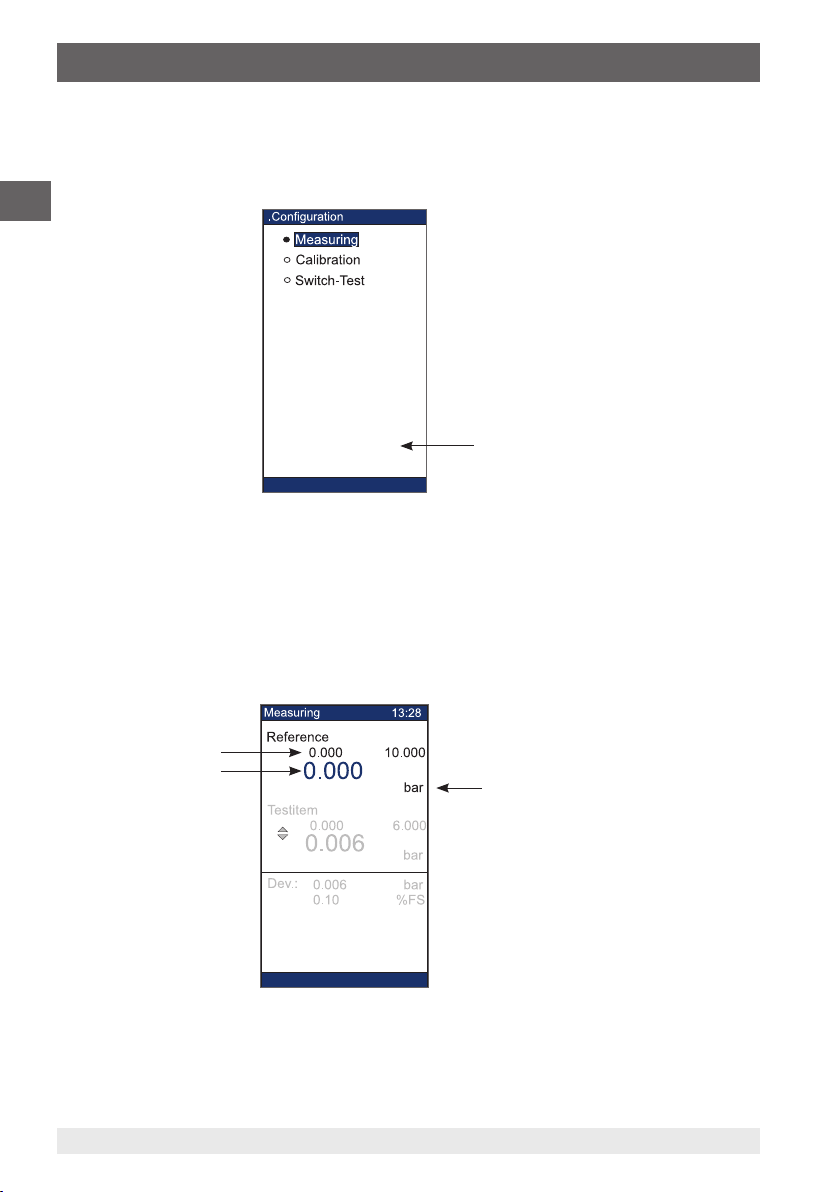
6.1 Menu structure (operating modes)
Through the SETUP menu, the required operating mode can be easily selected (see
drawing below).
EN
Functions
CPH-Info
ReferenceSensor
Ref. Sensor-list
CPH-Configuration
Interface
CLEAR CalData
CPH switch off
SELECTSELECT SELECT
SELECT SELECTSELECT
optional
Operating modes Configuration SETUP menu
It is possible to change the test item display (pressure ↔ electrical signal) via
24 WIKA operating instructions, model CPH7650
14261987.01 03/2018 EN/DE
Page 25
6. Commissioning, operation
6.2 Explanation of the display
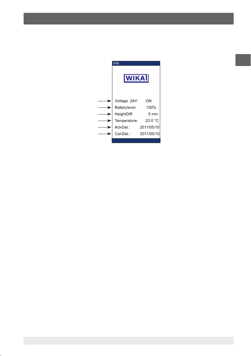
6.2.1 Instrument status messages shortly after switching on the CPH7650
Directly after the instrument is switched on, the following status messages are displayed
briefly:
CPH7650
a
b
c
d
e
f
a) The voltage supply of 24 V (available at the upper end of instrument) can, during the
configuration of each operating mode, be switched on or off. If it is not needed for a
measurement, then it should be switched off, in order to conserve energy.
b) Current battery capacity (see chapter 6.4.5 “SETUP additional menu items: CPH
configuration”)
c) Height difference in mm
In the “SETUP\CPH configuration” menu, set the height difference between the test
item and the CPT6000 reference pressure sensor. This value influences an automatic
correction calculation in order to eliminate any pressure difference based on a
medium column. This value must be correct for the following measuring procedure
and/or be adjusted accordingly in the “SETUP/CPH configuration” menu (see chapter
6.4.5 “SETUP additional menu items: CPH configuration”).
d) Temperature in [°C]
In the “SETUP\CPH configuration” menu, the temperature (ambient temperature) is
entered. This value can be adjusted accordingly in the “SETUP\CPH configuration”
menu (see chapter 6.4.5 “SETUP additional menu items: CPH configuration”).
e) Current date of the integrated real-time clock
In the “SETUP\CPH configuration” menu, the date of the real-time clock is set, which is
later marked on the calibration certificate. This value must be correct for the following
measuring procedure in calibration mode and/or be adjusted accordingly in the
“SETUP/CPH configuration” menu (see chapter 6.4.5 “SETUP additional menu items:
CPH configuration”).
f) Calibration date for the electrical measuring inputs of the CPH7650 (Year/Month/Day)
Following the status messages, the display returns to the screen for the last-selected
operating mode (see following chapter 6.2.3 “Display contents of the operating
modes”).
EN
14261987.01 03/2018 EN/DE
25WIKA operating instructions, model CPH7650
Page 26
6. Commissioning, operation
6.2.2 Switching the pressure calibrator off
The instrument is switched off using the “Switch off CPH” menu item in the first submenu.
For this, press the SETUP key, select the “Switch off CPH” menu item and confirm using
the SELECT button. Switch off the CPH7650.
EN
Functions
CPH-Info
ReferenceSensor
Ref. Sensor-list
CPH-Configuration
Interface
CLEAR CalData
CPH switch off
Switching off
6.2.3 Display contents of the operating modes
Operating mode: MEASURING
When a CPH7650 with a CPT6000 reference pressure sensor connected to it is first
switched on, the instrument (after displaying a brief status message) switches to
MEASURING mode (see following figure)
Display: MEASURING with reference pressure sensor only (without test item)
a
b
c
a) Measuring range of the CPT6000 reference pressure sensor (which is currently
connected)
b) Current measured value of the reference pressure sensor
c) Pressure unit (adjustable via menu)
14261987.01 03/2018 EN/DE
26 WIKA operating instructions, model CPH7650
Page 27

6. Commissioning, operation
In MEASURING mode, at the same time as the reference-pressure value, a test item can
also be displayed on the screen (see following figure). With respect to the configuration,
see chapters 6.3.1 “MEASURING mode” and 6.3.2 “MEASURING mode (with test item)”.
Display: MEASURING with test item
d
a
b
c
P I/U
switchable
e
f
Pressure signal (test item) Electrical signal (test item)
a) Measuring range of the test item
b) Current measured value of the test item
c) Deviation/difference between reference and test item in the current pressure units and
in % of the measuring span (% FS) or % of reading (% rd)
d) Pressure unit (of the test item)
e) Original output signal of the test item
f) Current value of the output signal of the test item
EN
14261987.01 03/2018 EN/DE
27WIKA operating instructions, model CPH7650
Page 28
6. Commissioning, operation
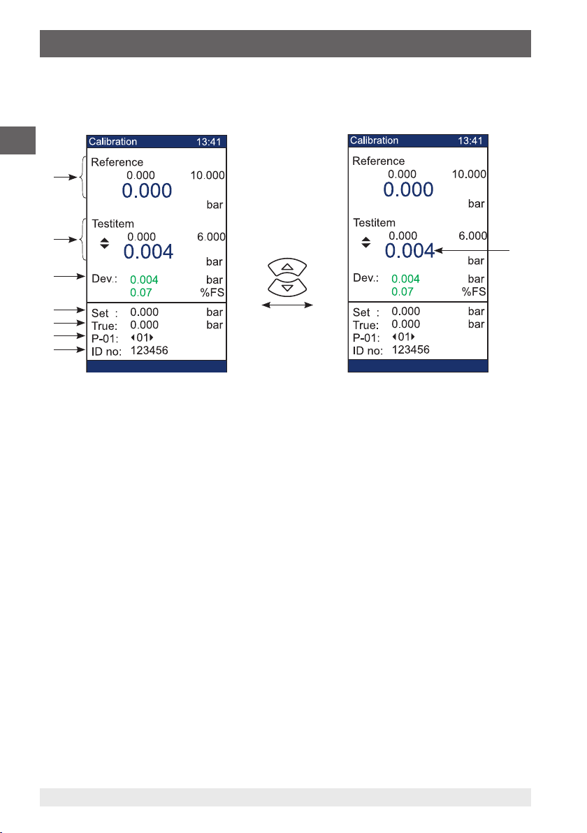
Operating mode: CALIBRATION
In the CALIBRATION mode the data shown above the dashed dividing line is the same
as in the “MEASURING with test item” mode.
EN
a
b
c
d
e
P I/U
switchable
f
g
Pressure signal (test item) Electrical signal (test item)
a) Current measured value of the CPT6000 reference pressure sensor
b) Current measured value of the test item
c) Deviation between the test item and reference
d) Set point of the calibration
e) Actual value of the calibration
f) P - 01: Test item No. 1
<01>: Test step No. 1
g) IDENT number of the test item
h) Current value of the output signal of the test item
h
28 WIKA operating instructions, model CPH7650
14261987.01 03/2018 EN/DE
Page 29

6. Commissioning, operation
Operating mode: SWITCH TEST
In the SWITCH TEST mode, along with the reference pressure sensor data (see
MEASURING mode), the status and switch points of the pressure switch are also
displayed.
a
f
b
c
d
e
a) Current measured value of the CPT6000 reference pressure sensor
b) Current switching status/status of the pressure switch
c) Opening switch point
d) Closing switch point
e) Hysteresis/separation between opening and closing of the switch
f) Pressure unit (adjustable via menu)
EN
6.2.4 Content of the SETUP menu
a
b
c
d
e
f
g
h
i
y
k
14261987.01 03/2018 EN/DE
Functions
CPH-Info
ReferenceSensor
Ref. Sensor-list
CPH-Configuration
Interface
CLEAR CalData
CPH switch off
29WIKA operating instructions, model CPH7650
Page 30

6. Commissioning, operation
a) Operating mode MEASURING
■
To measure working or process pressures
■
For comparative measurements and/or calibrations (without data recording) of
EN
mechanical* and electrical pressure measuring instruments (supply and display of
the test item through the CPH7650)
→ For further information, see chapter 6.3.1 “MEASURING mode” and
6.3.2 “MEASURING mode (with test item)”
b) Operating mode CALIBRATION
■
For on-site calibration of mechanical 1) and electrical pressure measuring
instruments (without PC). In this case the data sets (for up to 16 test items, each
with up to 32 test steps including date and time) are recorded within the CPH7650.
1) For mechanical dial instruments, the test item's measured value must be entered via the numeric keypad.
→ For more information please refer to chapter 6.3.3 “Mode CALIBRATION”
c) Operating mode SWITCH TEST
■
For the easy checking of pressure switches, including automatic calculation of the
switch hysteresis.
→ For more information please refer to chapter 6.3.7 “SWITCH TEST mode”
d) Operating functions
■
Tare: Offset correction of the reference pressure value
■
Min/Max: Minimum/Maximum memory
■
Alarm: Min/Max alarm (visual and audible)
■
Filter: Damping/smoothing of the reference sensor signal
→ For further information see chapter 6.4.1 „SETUP additional menu items: Functions“
e) General CPH7650 instrument data
■
Calibration data for the electrical measuring inputs
■
Firmware number
■
Serial number of the instrument
→ For more information please refer to chapter 6.4.2 “SETUP additional menu items:
CPH info”
30 WIKA operating instructions, model CPH7650
14261987.01 03/2018 EN/DE
Page 31

6. Commissioning, operation
f) Data for the currently connected reference pressure sensor
■
Measuring range
■
Accuracy class
■
Pressure type of the sensor
■
Information in the event of reference sensor overpressure
■
Calibration data for the reference sensor
→ For more information please refer to chapter 6.4.3 “SETUP additional menu items:
Reference sensor”
g) Reference sensor list
■
List of the stored reference sensors that can be attached and are calibrated.
→ For more information please refer to chapter 6.4.4 “SETUP additional menu items:
Reference sensor list”
h) CPH configuration
■
Info: On battery capacity
■
Setting options from: Menu language, system time/system clock, display brightness,
Powersave function (automatic energy saving mode; see chapter 6.4.5 “SETUP
additional menu items: CPH configuration”)
■
Input options:
- Ambient temperature during the calibration
- Height difference existing between the reference pressure sensor and test item
(see chapter 4.5.1 “Requirements for test assemblies with the CPH7650”).
EN
→ For more information please refer to chapter 6.4.5 “SETUP additional menu items:
CPH configuration”
i) Interface
■
USB interface, incl. setting of the baud rate
→ For more information please refer to chapter 6.4.6 “SETUP additional menu items:
Interface”
j) CLEAR CalProg
■
Delete all stored calibration data (clear and reset all memory space)
→ For more information please refer to chapter 6.4.7 “SETUP additional menu items:
CLEAR CalProg”
k) Switching off the model CPH7650 pressure calibrator
→ For more information please refer to chapter 6.2.2 “Switching the pressure calibrator
off”
14261987.01 03/2018 EN/DE
31WIKA operating instructions, model CPH7650
Page 32

6. Commissioning, operation
6.3 Operating modes
6.3.1 MEASURING mode
1. Access SETUP menu
EN
Functions
CPH-Info
ReferenceSensor
Ref. Sensor-list
CPH-Configuration
Interface
CLEAR CalData
CPH switch off
Press
(SETUP key)
Selection
(Menu item)
2. Preparing for MEASURING
..Measuring
a
b
c
d
e
f
g
3. Mode: MEASURING
Pressure unit
(adjustable via
menu)
SELECT
SELECT
Confirmation
(of the selection)
Selection
(Menu item);
configuration, see
next page
Confirmation
(of the input)
32 WIKA operating instructions, model CPH7650
14261987.01 03/2018 EN/DE
Page 33

6. Commissioning, operation
In order to switch the instrument into MEASURING mode, follow the instructions on the
previous page.
The following is a more detailed explanation of point 2 “Preparation for MEASURING”:
a) Test item type and test item measuring signal: [----] For measurement without test item
b) Start of measuring range and end of measuring range of the test item currently to be
calibrated
c) Unit and resolution (submenu)
Select and confirm (standard units) via
Customer-specific unit; with respect to bar
(input via numeric keypad)
Display resolution in operating mode via
(back with )
d) Measurement uncertainty of the test item in % FS (i.e. of the span) or % rd (i.e. of
reading)
e) Measurement type for the test item (gauge or absolute)
f) Test medium (pneumatic → gas or hydraulic → oil)
g) Voltage supply for test item (on/off)
If no external supply is required for the test item, “OFF” should be selected to conserve
energy.
EN
XXX
◁▷ ◀▶
0.00 Parameter input via numeric keypad
ENTER
Short info:
14261987.01 03/2018 EN/DE
Current cursor position; Alter via
Parameter selection from list or menu via
Input confirmation
CLEAR
Clear entry
33WIKA operating instructions, model CPH7650
Page 34

6. Commissioning, operation
6.3.2 MEASURING mode (with test item)
1. Access SETUP menu
EN
2. Prepare MEASUREMENT
a
b
c
d
e
f
g
Functions
CPH-Info
ReferenceSensor
Ref. Sensor-list
CPH-Configuration
Interface
CLEAR CalData
CPH switch off
SELECT
Press
(SETUP key)
Selection
(Menu item)
Confirmation
(of the selection)
Selection
(Menu item);
configuration, see
next page
Confirmation
(of the input)
3. Mode: MEASURING
Deviation
SELECT
P I/U
switchable
Pressure signal (test item) Electrical signal (test item)
34 WIKA operating instructions, model CPH7650
14261987.01 03/2018 EN/DE
Page 35

6. Commissioning, operation
Should the instrument be switched into “MEASURING” mode (with test item = display
of the test signal as an electrical signal or as a pressure), in order to carry out a
comparative measurement or calibration without measured-value recording, then follow
the instructions on the previous page.
The following is a more detailed explanation of point 2 “Preparation for MEASURING”
a) Test item type and test item measuring signal
0 ... 20 mA / 4 ... 20 mA / 0 ... 1 V / 0 ... 2 V / 0 ... 5 V / 0 ... 10 V / or mechanical for dial
pressure gauge
If a comparative measurement with a mechanical dial instrument (test item) is being
made, then the gauge’s measured value should be entered via the numeric keypad and
confirmed with the ENTER key.
b) Start of measuring range and end of measuring range of the test item currently to be
calibrated
c) Unit and resolution (submenu)
Select and confirm (standard units) via
Customer-specific unit; with respect to bar
(input via numeric keypad)
EN
Display resolution in operating mode via
(back with )
d) Measurement uncertainty of the test item in % FS (i.e. of the span) or % rd (i.e. of
reading)
e) Measurement type for the test item (gauge or absolute)
f) Test medium (pneumatic → gas or hydraulic → oil)
g) Voltage supply for test item (on/off)
If no external supply is required for the test item, “OFF” should be selected to conserve
energy.
XXX
◁▷ ◀▶
0.00 Parameter input via numeric keypad
ENTER
Short info:
14261987.01 03/2018 EN/DE
Current cursor position; Alter via
Parameter selection from list or menu via
Input confirmation
CLEAR
Clear entry
35WIKA operating instructions, model CPH7650
Page 36

6. Commissioning, operation
Functions
CPH-Info
ReferenceSensor
Ref. Sensor-list
CPH-Configuration
Interface
CLEAR CalData
CPH switch off
6.3.3 Mode CALIBRATION
1. Access SETUP menu
EN
2. Preparation for CALIBRATION
a
b
c
d
e
f
g
h
i
y
k
l
m
n
SELECT
Press
(SETUP key)
Selection
(Menu item)
Confirmation
(of the selection)
Selection
(Menu item);
configuration, see
next page
SELECT
Confirmation
(of the input)
3. Mode: Calibration
Deviation
36 WIKA operating instructions, model CPH7650
Pressure signal (test item) Electrical signal (test item)
P I/U
switchable
14261987.01 03/2018 EN/DE
Page 37

6. Commissioning, operation
In order to put the instrument into CALIBRATION mode, the procedure on the previous
page should be followed.
The following is a more detailed explanation of point 2 “Preparation for CALIBRATION”
a) Number of the calibration and therefore the test item (up to 16 calibrations, each with
up to 32 test steps, can be predefined and then recorded)
b) Test item type and test item measuring signal
0 ... 20 mA / 4 ... 20 mA / 0 ... 1 V / 0 ... 2 V / 0 ... 5 V / 0 ... 10 V / or mechanical for dial
pressure gauge
c) IDENT number of the test item
d) Measuring point number of the test item
e) Start of measuring range and end of measuring range of the test item currently to be
calibrated
f) Unit and resolution (submenu)
Select and confirm (standard units) via
Customer-specific unit; with respect to bar
(input via numeric keypad)
Display resolution in operating mode via
(back using )
g) Measurement uncertainty of the test item in % FS (i.e. of the span) or % rd (i.e. of
reading)
h) Measurement type for the test item (gauge or absolute)
i) Test medium (pneumatic → gas or hydraulic → oil)
j) Voltage supply for test item (on/off) [If no external supply is required for the test item,
“OFF” should be selected to conserve energy]
k) Number of the test point x
l) Optional delay time [sec] (see chapter 6.3.4 “CALIBRATION mode (preparing the test
points of a calibration)”)
m) Value of the test point x (input via numeric keypad)
(Test point x+1 and x-1 accessible via
)
n) True value of the test item (will be recorded during the calibration)
EN
14261987.01 03/2018 EN/DE
37WIKA operating instructions, model CPH7650
Page 38

6. Commissioning, operation
6.3.4 CALIBRATION mode (preparing the test points of a calibration)
1. Test point
(define)
EN
1. Test point
(defined)
ENTER
Calibration/test item No. 1
Select from menu item: “Set
point”
No. of the test point
Set point of the test point
Entry of the test point (e.g.
0 bar) via numeric keypad and
confirmation with
←
Test point No. 1 = 0 bar
2. Test point
(define)
← 2. Call up test point
(with
back to previous test
point)
x. Test point
(define)
38 WIKA operating instructions, model CPH7650
14261987.01 03/2018 EN/DE
Page 39

6. Commissioning, operation
With this example, the definition of individual test points/pressure steps for a calibration is
clarified. It is possible to prepare up to 16 calibrations, each with up to 32 test steps.
Accessing the menu item
Via
and selection of the menu item: CALIBRATION (or see chapter 6.3.3 “Mode
CALIBRATION”)
Enter the desired test points in the way described on the previous page.
With the calibration of pressure measuring instruments with electrical output signals
(pressure transmitters/transmitters) the reference is calibrated to the display (i.e. the
pressure is always adjusted so that the reference value matches the set point exactly).
As an exact setting of the pressure is not always possible under certain circumstances,
the true reference value is also recorded along with the actual value (test item value)
and the set point (reference value). With the WIKA-Cal software, this can be listed in the
calibration certificate.
If the calibration is to follow DKD/DAkkS guidelines, then the measured
value for each subsequent test point should not be recorded until a defined
time has passed (for example 30 seconds), consisting of a load change time
and settling time (see figure A: Calibration cycle to DKD/DAkkS guideline 6
- 1 for measurement uncertainty > 0.6 % of measuring span).
Z
M1
M2
2 Minutes
30 s 30 s
For Bourdon tube
pressure gauges:
5 minutes
Readings
EN
14261987.01 03/2018 EN/DE
Figure A
39WIKA operating instructions, model CPH7650
Page 40

6. Commissioning, operation
EN
optional delay time [sec]
Input via numeric input keypad and confirmation
ENTER
with
With the entry of such a delay time, the acceptance/recording of the test point is blocked
for this duration. (In the above example, after the first test point has been recorded,
30 seconds must pass before the second test point can be recorded.)
Should all test points need to be cleared or reset, since the new calibration
consists of fewer test points than the previous test series, the CLEAR button
simply needs to be pressed. This will clear and reset the current and all
subsequent test points.
(This process can take several seconds.)
Should all saved calibration data for all calibrations need to be cleared at
a single time, see chapter 6.4.7 “SETUP additional menu items: CLEAR
CalProg”.
40 WIKA operating instructions, model CPH7650
14261987.01 03/2018 EN/DE
Page 41

6. Commissioning, operation
6.3.5 CALIBRATION mode (calibration of a pressure transmitter)
1. Test point
(e.g. 0 bar)
Deviation
No. of test item
and No. of test
point
2. Test point
(e.g. 1 bar)
ENTER
Generate the specified set
point in accordance with the
reference display (establish
a pressure-free condition/
atmosphere) and with
←
Record the measured values of
the test point
EN
Deviation
No. of test item
and No. of test
point
2. Test point
Deviation
No. of test item
and No. of test
x. Test point
14261987.01 03/2018 EN/DE
point
ENTER
Generate the specified set
point in accordance with the
reference display using the
pressure generator
Record the measured values of
the test point
(with
test point)
back to previous
41WIKA operating instructions, model CPH7650
Page 42

6. Commissioning, operation
6.3.6 CALIBRATION mode (calibration of a pressure gauge)
1. Test point
(e.g. 0 bar)
EN
Deviation
Generate the specified set point
in accordance with the test
item display using the pressure
generator
No. of test item
and No. of test
2. Test point
(e.g. 1 bar)
Deviation
No. of test item
and No. of test
2. Test point
point
point
ENTER
If the set point = 0 bar, the
calibration assembly must
be brought to a pressure-free
condition/vented to atmosphere
(test item must indicate 0 bar;
if necessary, make a zero point
setting) and with
←
Record the measured values of
the test point
Generate the specified set point
in accordance with the test
item display using the pressure
generator
Deviation
No. of test item
and No. of test
x. Test point
ENTER
point
Record the measured values of
the test point
(with
test point)
back to previous
42 WIKA operating instructions, model CPH7650
14261987.01 03/2018 EN/DE
Page 43

6. Commissioning, operation
Functions
CPH-Info
ReferenceSensor
Ref. Sensor-list
CPH-Configuration
Interface
CLEAR CalData
CPH switch off
6.3.7 SWITCH TEST mode
1. Access SETUP MENU
2. Preparing the SWITCH
TEST
a
b
SELECT
Press
(SETUP key)
EN
Selection
(Menu item)
Confirmation
(of the selection)
Selection
(Menu item);
configuration, see
next page
3. Mode: SWITCH TEST
switching status
Switch points
14261987.01 03/2018 EN/DE
Current
Hysteresis
SELECT
Confirmation
(of the input)
Before the pressure switch test After the pressure switch test
43WIKA operating instructions, model CPH7650
Page 44

6. Commissioning, operation
In order to put the instrument into SWITCH TEST mode, the procedure on the previous
page should be followed.
EN
The switch test is not suitable for electronic switches (e.g. PNP- or NPN
switches), but is only for mechanical, potential-free switches.
The following is a more detailed explanation of point 2 “Preparation for SWITCH TEST”
a) Voltage supply for test item (on/off) [If no external supply is required for the test item,
“OFF” should be selected to conserve energy]
b)Unit and resolution (submenu)
Select and confirm (standard unit) via
Customer-specific unit; with respect to bar
(input via numeric keypad)
Display resolution in operating mode via
(back with )
The calculated measured values of the two switch points and the hysteresis
can be reset by pressing the “0” key.
44 WIKA operating instructions, model CPH7650
14261987.01 03/2018 EN/DE
Page 45

6. Commissioning, operation
6.4 SETUP additional menu items
6.4.1 SETUP additional menu items: Functions
a
b
c
d
e
a) Current measured value of the connected CPT6000 reference pressure sensor
b) Offset function that influences the current measured value. The value entered is added
to the current measured value.
c) (e.g. Ref. 0.000 and Tare: 1.000 → [new] Ref. 1.000)
d) Minimum and maximum value memory
The memory is reset by highlighting the value with the cursor (via
CLEAR button.
d) Audible and visible alarm function
upper alarm limit: ≥ bar
lower alarm limit: ≤ bar
If the current measured value goes outside the set alarm limits, an intermittent alarm
tone sounds and the lower status line blinks.
Activation via:
Move the cursor to the field next to the word Alarm that reads <OFF> and via
change it to <ON>.
Deactivation via:
set back to <OFF>
e) Filter [1-5]:
Damping/smoothing of the reference sensor signal
Definition of the numbers:
1 = no additional smoothing ... 5 = strong smoothing
..Functions
0.000
Ref.:
0.000
Tare:
0.000
Min:
0.000
Max:
Alarm:
Filter:
Ref. = rel. Pressure
Offset pressure
ON
10.00
≥
-1.00
≤
0
bar
bar
bar
bar
bar
bar
ENTER
Select menu item
Input via numeric keypad
Confirmation of input
(Clear deletes the input, or
resets the MIN/MAX memory)
) and pressing the
EN
14261987.01 03/2018 EN/DE
45WIKA operating instructions, model CPH7650
Page 46

6. Commissioning, operation
6.4.2 SETUP additional menu items: CPH info
EN
Info
CPH7650
CPH6000
a
b
c
Cal-Dat.: 2011/05/10
Firmware: 20.05
Serial No: 6000.001
In this menu item general data are listed, such as:
a) Calibration date for the calibration of the electrical measuring inputs of the CPH7650
(Year/Month/Day)
b) Firmware version of the CPH7650
c) Serial number of the CPH7650
46 WIKA operating instructions, model CPH7650
14261987.01 03/2018 EN/DE
Page 47

6. Commissioning, operation
6.4.3 SETUP additional menu items: Reference sensor
..ReferenceSensor
a
b
c
d
e
f
Sensor no:
R.-Start:
Range-End:
Unit:
Class:
%FS
Pressuretype:
Overload:
Read
362A
0.00
10.00
bar
0.025
0 sec
EN
rel
g
h
i
Ref-Value:
Offset:
Cal-Dat.:
Reference sensor
0.001
0.000
2011/05/10
a) Sensor number of the currently connected CPT6000 reference pressure sensor
b) Start of measuring range and end of measuring range for the currently connected
CPT6000 reference pressure sensor
c) Basic pressure unit of the CPT6000 reference pressure sensor
d) Accuracy of the measuring chain of the CPH7650 with connected CPT6000 reference
pressure sensor
e) Pressure type of the currently connected CPT6000 reference pressure sensor
(overpressure (gauge pressure) or absolute pressure)
f) Length of time for which the CPT6000 reference pressure sensor was unacceptably
overloaded.
If the value here is not equal to zero, then it is highly probable that the
instrument no longer meets its specified class accuracy. The only solution
for this is an immediate recalibration. (For absolute pressure sensors < 1 bar
this function is deactivated, since for this measuring range atmospheric
pressure already represents an overload)
g) Current measured value of the connected CPT6000 reference pressure sensor
h) This menu option only appears if the CPH7650’s reference pressure sensor is an
absolute pressure sensor.
Through this menu option the measured value of the reference pressure sensor can be
adjusted. This should only be used, however, as close as possible to the absolute zero,
and using a reference that is at least 4 times more accurate.
i) Calibration date of the CPT6000 reference pressure sensor (Year/Month/Day)
14261987.01 03/2018 EN/DE
47WIKA operating instructions, model CPH7650
Page 48

6. Commissioning, operation
6.4.4 SETUP additional menu items: Reference sensor list
..Ref. Sensor-list
362A
Rp52
Kd35
Rp56
----
362A
06
07
08
09
10
10.000
2011/05/10
----
----
----
----
----
0.000
bar
0.025
Selection
of a listed sensor with
EN
a
Current
01
02
b
03
04
05
R.-Start:
Range-End:
c
Unit:
Cal-Dat.:
Class:
The CPH7650 pressure calibrator supports up to 10 CPT6000 reference pressure
sensors.
These are listed in this menu.
a) Currently connected CPT6000 reference pressure sensor
b) Sensor list of the supported CPT6000 reference pressure sensors (calibrated with the
instrument)
c) Data of the sensor which has been selected using the cursor
(calibration date: Year/Month/Day)
48 WIKA operating instructions, model CPH7650
14261987.01 03/2018 EN/DE
Page 49

6. Commissioning, operation
6.4.5 SETUP additional menu items: CPH configuration
a
b
c
d
e
ENTER
f
g
h
Selection of menu item
Input via numeric keypad
Confirmation of input
(Clear deletes the input)
This menu section lists general instrument settings, such as:
a) Input possibility for an ambient temperature
b) Input possibility for a height difference between reference pressure sensor and test
item, used in the automatic correction (deduction of a medium column)
c) Selection of the menu language (German/English/French/Spanish/Italian)
d) Date of the system clock (Year/Month/Day)
e) Time of the system clock (Hours/Minutes/Seconds)
f) Brightness of the backlighting of the display
g) Powersave function (automatic switch-off time for backlighting and internal 24 V test
item power supply).
If the instrument is idle for the set switch-off time (no buttons pressed and no interface
communication), then the backlighting and the 24 V test item power supply will
be switched off, until any button is pressed (except ON/OFF) or the instrument is
addressed over the interface.
h) Current battery capacity
At 10 % the low battery charge warning, “low BAT” is shown in the display.
EN
14261987.01 03/2018 EN/DE
49WIKA operating instructions, model CPH7650
Page 50

6. Commissioning, operation
6.4.6 SETUP additional menu items: Interface
..Interface
USB
EN
RS232
(8N1)
The USB interface can be switched on and off. In order to extend the battery life, the USB
interface should be deactivated when not in use.
ON
9600
SELECT
Select serial interface
Confirm selection
Change between interface type
and baud rate
6.4.7 SETUP additional menu items: CLEAR CalProg
If the SETUP menu item CLEAR CalData is selected with the cursor and then the
SELECT button pressed 2 x, then all stored calibration data will be deleted or reset.
The status of the deletion process is shown at the left of the lower info
screen.
50 WIKA operating instructions, model CPH7650
14261987.01 03/2018 EN/DE
Page 51

6. Commissioning, operation
6.5 Connection of the model CPT6000 reference pressure sensor
WARNING!
■
Only use model CPT6000 reference pressure sensors!
■
Using other sensors could damage both the pressure calibrator and the
reference pressure sensor.
■
To change the sensor, switch off the pressure calibrator and make sure
the system is vented. Before switching the instrument on, connect the
sensor, otherwise it may not be correctly identified by the instrument.
■
When the CPH7650 is switched on, the CPT6000 reference pressure
sensor must not be under pressure, but rather should be at atmospheric
pressure. For overpressure or gauge pressure sensors, there is a
pressure compensation vent in the top of the sensor under the plastic
fitting. This vent (with integrated diaphragm) must always remain clear!
CAUTION!
Only ever use the original WIKA sensor connection cable in the operation of
CPT6000 reference pressure sensors.
6.6 Voltage supply
The internal Lithium-Ion battery, which can be easily charged with the battery charger
supplied with the equipment, serves as the voltage supply for the instrument. To charge
the CPH7650 rechargeable batteries, the mains plug of the charger/power supply unit
must always be plugged into a mains socket and accessible, so that one can always
remove it from the mains socket without difficulty.
EN
CAUTION!
For EMC reasons, never use the CPH7650 with a power supply unit
connected.
The instrument should be fully charged before being put into operation.
The battery capacity status (charge state in %) is displayed shortly after the instrument
is switched on and can be learnt about in chapter 6.4.5 “SETUP additional menu items:
CPH configuration”.
When the mains lead is connected to the CPH7650, the battery will be
charged, even if the CPH7650 is switched off
14261987.01 03/2018 EN/DE
51WIKA operating instructions, model CPH7650
Page 52

6. Commissioning, operation
■
When the battery charger is no longer being used, the mains plug should be
disconnected from the mains socket. Do not leave the battery charger connected to
the rechargeable battery for longer than one day, since overloading can shorten its
EN
service life.
■
Should the rechargeable battery still not be fully charged after 24 hours, contact the
manufacturer. When not being used, a fully charged battery will lose its charge over
time.
■
Extreme temperatures have an adverse effect on battery charging. As a result, the
battery may first need to be either cooled or warmed, as appropriate.
6.7 Charging/discharging the Lithium-Ion rechargeable batteries
CAUTION!
The temperature range over which the Lithium-Ion battery can be charged is
10 ... 45 °C. Charging the Lithium-Ion battery at temperatures outside of this
range may lead to heating or damage. In addition, the performance of the
Lithium-Ion battery can be affected and the service life reduced.
WARNING!
In order to charge the Lithium-Ion battery, never use any instrument other
than that specified by WIKA. When the Lithium-Ion battery is used in
instruments other than the instruments specified by WIKA, the performance
and service life of the Lithium-Ion battery may be reduced, and, should the
instrument cause an abnormal current to flow, it can cause the Lithium-Ion
battery to become hot, explode or ignite and result in serious injury.
CAUTION!
The temperature range over which the Lithium-Ion battery can be
discharged is -10 ... +60 °C. Use of the Lithium-Ion battery outside of this
temperature range may affect the performance of the battery or may reduce
its service life.
52 WIKA operating instructions, model CPH7650
14261987.01 03/2018 EN/DE
Page 53

6. Commissioning, operation
6.8 Pressure measurement
For pressure calibration, connect the test item to the test item connection. Choose a
reference sensor that is suitable for the pressure range and accuracy.
CAUTION!
Pressure sensors may be damaged and/or injuries may occur to
the personnel due to improper application of pressure. For a better
understanding with respect to overpressure and burst pressure, follow
the specifications laid down in these operating instructions (see chapter
3 “Specifications”).
The calibrator display will indicate “OL” when an inappropriate pressure is
applied. As soon as “OL” is observed on any pressure display, the pressure
should be reduced immediately to prevent damage or possible physical
injury. “OL” is displayed if the pressure exceeds the nominal range by 110 %.
Use the ZERO button to zero the pressure sensor once it is vented to
atmospheric pressure.
Media compatibility
CAUTION!
The calibrator should only be used with clean, dry air! To prevent
contamination by the test items, the use of a dirt trap is recommended (see
chapter 10 “Accessories”)!
6.9 Measuring and sourcing current (4 ... 20 mA)
To measure current, use the input terminals via the display on the calibrator and select
the mA function. Current is measured in mA and percentage of the measuring range. The
measuring range of the calibrator is set to 0 % at 4 mA and 100 % at 20 mA.
EN
14261987.01 03/2018 EN/DE
53WIKA operating instructions, model CPH7650
Page 54

7. Maintenance, cleaning and recalibration
7. Maintenance, cleaning and recalibration
7.1 Maintenance
This model CPH7650 portable pressure calibrator is maintenance-free.
EN
Repairs must only be carried out by the manufacturer.
CAUTION!
To avoid personal injury or damage to the calibrator, only use accessories
supplied by WIKA and ensure that no water finds its way into the case.
7.2 Cleaning
CAUTION!
■
Before cleaning, vent and switch off the pressure calibrator.
■
In order not to damage the display or case, do not use any solvent agents
or abrasives for cleaning.
■
Clean the instrument with a moist cloth.
■
Neither electrical connections nor pressure connections must come into
contact with moisture.
For information on returning the instrument see chapter 9.2 “Return”.
7.3 Recalibration
DKD/DAkkS certificate - official certificates:
We recommend that the instrument is regularly recalibrated by the manufacturer, with
time intervals of approx. 12 months. In addition, every factory recalibration includes an
extensive free-of-charge check of all system parameters with respect to their compliance
with the specifications. The basic settings will be corrected if necessary.
54 WIKA operating instructions, model CPH7650
14261987.01 03/2018 EN/DE
Page 55

8. Faults
8. Faults
Indication Cause Measures
OL
-OL
No display or
undefinable
characters,
instrument is not
responding to a push
of a button
Low battery voltage,
functioning is only guaranteed
for a short period of time
Reading is significantly above
or below the measuring range
Battery is empty Charging the battery
System error Switch off the instrument, wait for a
Technical fault Send in for repair
Charging the battery
Check: Is the pressure within the
permissible measuring range of the
sensor?
→ Reduce the applied pressure
short period of time, switch on again
CAUTION!
If faults cannot be eliminated by means of the measures listed above, the
hand-held pressure calibrator must be shut down immediately, and it must
be ensured that pressure and/or signal are no longer present, and it must be
prevented from being inadvertently put back into service.
In this case, contact the manufacturer.
If a return is needed, please follow the instructions given in chapter 9.2
„Return“.
EN
14261987.01 03/2018 EN/DE
55WIKA operating instructions, model CPH7650
Page 56

9. Dismounting, return and disposal
9. Dismounting, return and disposal
WARNING!
EN
9.1 Dismounting
Only disconnect the portable pressure calibrator once the system has been
depressurised!
9.2 Return
When returning the instrument, use the original packaging or a suitable transport
packaging.
To avoid damage:
1. Wrap the instrument in an antistatic plastic film.
2. Place the instrument, along with shock-absorbent material, in the packaging. Place
shock-absorbent material evenly on all sides of the transport packaging.
3. If possible, place a bag containing a desiccant inside the packaging.
4. Label the shipment as carriage of a highly sensitive measuring instrument.
Residual media at the instrument can result in a risk to persons, the
environment and equipment.
Take sufficient precautionary measures.
WARNING!
Strictly observe the following when shipping the instrument:
All instruments delivered to WIKA must be free from any kind of hazardous
substances (acids, bases, solutions etc.).
Information on returns can be found under the heading “Service” on our local
website.
9.3 Disposal
Incorrect disposal can put the environment at risk.
Dispose of instrument components and packaging materials in an environmentally
compatible way and in accordance with the country-specific waste disposal regulations.
This marking on the instruments indicates that they must not be disposed of
in domestic waste. The disposal is carried out by return to the manufacturer
or by the corresponding municipal authorities.
56 WIKA operating instructions, model CPH7650
14261987.01 03/2018 EN/DE
Page 57

10. Accessories
10. Accessories
Accessories Order number
Dirt trap 13477103
USB serial adapter 12981878
1 pair of test cables (red/black) 12981975
For further accessories, see current WIKA price list: Calibration technology.
EN
14261987.01 03/2018 EN/DE
57WIKA operating instructions, model CPH7650
Page 58

EN
58 WIKA operating instructions, model CPH7650
14261987.01 03/2018 EN/DE
Page 59

Inhalt
Inhalt
1. Allgemeines 61
2. Sicherheit 62
2.1 Bestimmungsgemäße Verwendung. . . . . . . . . . . . . . . 63
2.2 Personalqualifikation. . . . . . . . . . . . . . . . . . . . 64
2.3 Besondere Gefahren. . . . . . . . . . . . . . . . . . . . 64
2.4 Verwendung des Lithium-Ionen-Akkus. . . . . . . . . . . . . . 66
2.5 Beschilderung, Sicherheitskennzeichnungen . . . . . . . . . . . 68
3. Technische Daten 69
4. Aufbau und Funktion 71
4.1 Beschreibung . . . . . . . . . . . . . . . . . . . . . . 71
4.2 Front . . . . . . . . . . . . . . . . . . . . . . . . .72
4.3 Lieferumfang . . . . . . . . . . . . . . . . . . . . . . 73
4.4 Spannungsversorgung . . . . . . . . . . . . . . . . . . .73
4.5 Bedienoberfläche . . . . . . . . . . . . . . . . . . . . . 74
4.5.1 Anforderung an Prüfaufbauten mit dem CPH7650 . . . . . . . . . . . . .75
4.5.2 Wichtige Geräteeinstellungen bzgl. einer Kalibrierung via Kalibriermodus 75
4.5.3 Nullpunkteinstellung bzw. Offsetkorrektur . . . . . . . . . . . . . . . . . .76
4.5.4 Referenz-Drucksensor CPT6000. . . . . . . . . . . . . . . . . . . . . . .76
5. Transport, Verpackung und Lagerung 78
5.1 Transport. . . . . . . . . . . . . . . . . . . . . . . . 78
5.2 Verpackung . . . . . . . . . . . . . . . . . . . . . . .78
5.3 Lagerung. . . . . . . . . . . . . . . . . . . . . . . . 78
6. Inbetriebnahme, Betrieb 79
6.1 Menü-Struktur (Arbeitsmodi) . . . . . . . . . . . . . . . . . 80
6.2 Display-Darstellungen . . . . . . . . . . . . . . . . . . . 81
6.2.1 Geräte-Statusmeldung kurz nach dem Einschalten des CPH7650 . . . .81
6.2.2 Druckkalibrator ausschalten . . . . . . . . . . . . . . . . . . . . . . . . .82
6.2.3 Displayinhalte der Arbeitsmodi . . . . . . . . . . . . . . . . . . . . . . . .82
6.2.4 Inhalt des SETUP-Menüs . . . . . . . . . . . . . . . . . . . . . . . . . . .85
6.3 Arbeitsmodi . . . . . . . . . . . . . . . . . . . . . . .88
6.3.1 Modus MESSEN. . . . . . . . . . . . . . . . . . . . . . . . . . . . . . . .88
6.3.2 Modus MESSEN (mit Prüfling) . . . . . . . . . . . . . . . . . . . . . . . .90
6.3.3 Modus KALIBRIEREN. . . . . . . . . . . . . . . . . . . . . . . . . . . . .92
6.3.4 Modus KALIBRIEREN (die Prüfpunkte einer Kalibrierung vorbereiten) . .94
6.3.5 Modus KALIBRIEREN (die Kalibrierung eines Druckmessumformers) . .97
6.3.6 Modus KALIBRIEREN (die Kalibrierung eines Manometers) . . . . . . .98
6.3.7 Modus SCHALTERTEST . . . . . . . . . . . . . . . . . . . . . . . . . . .99
6.4 SETUP-Zusatzmenüpunkte . . . . . . . . . . . . . . . . 101
14261987.01 03/2018 EN/DE
DE
59WIKA Betriebsanleitung, Typ CPH7650
Page 60

Inhalt
6.4.1 SETUP-Zusatzmenüpunkte: Funktionen. . . . . . . . . . . . . . . . . .101
6.4.2 SETUP-Zusatzmenüpunkte: CPH-Info. . . . . . . . . . . . . . . . . . .102
6.4.3 SETUP-Zusatzmenüpunkte: Referenz-Sensor . . . . . . . . . . . . . . 103
6.4.4 SETUP-Zusatzmenüpunkte: Referenz-Sensor-Liste . . . . . . . . . . . 104
6.4.5 SETUP-Zusatzmenüpunkte: CPH-Einstellungen . . . . . . . . . . . . . 105
DE
6.4.6 SETUP-Zusatzmenüpunkte: Schnittstelle . . . . . . . . . . . . . . . . . 106
6.4.7 SETUP-Zusatzmenüpunkte: CLEAR KalProg . . . . . . . . . . . . . . .106
6.5 Anschluss des Referenz-Drucksensors Typ CPT6000 . . . . . . . 107
6.6 Spannungsversorgung . . . . . . . . . . . . . . . . . . 107
6.7 Laden/Entladen des Lithium-Ionen-Akkus . . . . . . . . . . . 108
6.8 Druckmessung. . . . . . . . . . . . . . . . . . . . . 109
6.9 Strom messen und geben (4 ... 20 mA) . . . . . . . . . . . . 109
7. Wartung, Reinigung und Rekalibrierung 110
7.1 Wartung . . . . . . . . . . . . . . . . . . . . . . . 110
7.2 Reinigung . . . . . . . . . . . . . . . . . . . . . . 110
7.3 Rekalibrierung . . . . . . . . . . . . . . . . . . . . . 110
8. Störungen 111
9. Demontage, Rücksendung und Entsorgung 112
9.1 Demontage . . . . . . . . . . . . . . . . . . . . . . 112
9.2 Rücksendung . . . . . . . . . . . . . . . . . . . . . 112
9.3 Entsorgung . . . . . . . . . . . . . . . . . . . . . . 112
10. Zubehör 113
Konformitätserklärungen finden Sie online unter www.wika.de.
60 WIKA Betriebsanleitung, Typ CPH7650
14261987.01 03/2018 EN/DE
Page 61

1. Allgemeines
1. Allgemeines
■
Der in der Betriebsanleitung beschriebene tragbare Druckkalibrator wird nach dem
aktuellen Stand der Technik gefertigt. Alle Komponenten unterliegen während der
Fertigung strengen Qualitäts- und Umweltkriterien. Unsere Managementsysteme sind
nach ISO 9001 und ISO 14001 zertifiziert.
■
Diese Betriebsanleitung gibt wichtige Hinweise zum Umgang mit dem Gerät. Voraussetzung für sicheres Arbeiten ist die Einhaltung aller angegebenen Sicherheitshinweise und Handlungsanweisungen.
■
Die für den Einsatzbereich des Gerätes geltenden örtlichen Unfallverhütungsvorschriften und allgemeinen Sicherheitsbestimmungen einhalten.
■
Die Betriebsanleitung ist Produktbestandteil und muss in unmittelbarer Nähe des
Gerätes für das Fachpersonal jederzeit zugänglich aufbewahrt werden.
■
Das Fachpersonal muss die Betriebsanleitung vor Beginn aller Arbeiten sorgfältig
durchgelesen und verstanden haben.
■
Die Haftung des Herstellers erlischt bei Schäden durch bestimmungswidrige Verwendung, Nichtbeachten dieser Betriebsanleitung, Einsatz ungenügend qualifizierten
Fachpersonals sowie eigenmächtiger Veränderung am Gerät.
DE
■
Es gelten die allgemeinen Geschäftsbedingungen in den Verkaufsunterlagen.
■
Technische Änderungen vorbehalten.
■
Werkskalibrierungen / DKD/DAkkS-Kalibrierungen erfolgen nach internationalen
Normen.
■
Weitere Informationen:
- Internet-Adresse: www.wika.de / www.wika.com
- zugehöriges Datenblatt: CT 17.02
- Anwendungsberater:
Tel.: +49 9372 132-9986
Fax: +49 9372 132-8767
info@wika.de
14261987.01 03/2018 EN/DE
61WIKA Betriebsanleitung, Typ CPH7650
Page 62

1. Allgemeines / 2. Sicherheit
Symbolerklärung
WARNUNG!
... weist auf eine möglicherweise gefährliche Situation hin, die zum Tod oder
zu schweren Verletzungen führen kann, wenn sie nicht gemieden wird.
DE
2. Sicherheit
VORSICHT!
... weist auf eine möglicherweise gefährliche Situation hin, die zu geringfügigen oder leichten Verletzungen bzw. Sach- und Umweltschäden führen
kann, wenn sie nicht gemieden wird.
Information
… hebt nützliche Tipps und Empfehlungen sowie Informationen für einen
effizienten und störungsfreien Betrieb hervor.
GEFAHR!
…kennzeichnet Gefährdungen durch elektrischen Strom. Bei Nichtbeachtung der Sicherheitshinweise besteht die Gefahr schwerer oder tödlicher
Verletzungen.
WARNUNG!
Vor Montage, Inbetriebnahme und Betrieb sicherstellen, dass der richtige
Referenz-Drucksensor hinsichtlich Messbereich, Ausführung und spezifischen Messbedingungen ausgewählt wurde.
Bei Nichtbeachten können schwere Körperverletzungen und/oder
Sachschäden auftreten.
Weitere wichtige Sicherheitshinweise befinden sich in den einzelnen
Kapiteln dieser Betriebsanleitung.
62 WIKA Betriebsanleitung, Typ CPH7650
14261987.01 03/2018 EN/DE
Page 63

2. Sicherheit
2.1 Bestimmungsgemäße Verwendung
Dieser tragbare Druckkalibrator dient als Kalibriergerät für unterschiedlichste Druckmessgeräte und wurde sowohl für den mobilen Einsatz als auch für stationäre Werkstatt- und
Laborprüfungen entwickelt. Durch die Kombination der integrierten elektrischen Pumpe
und des elektrischen Moduls wird neben dem klassischen Messen des Strom- und
Spannungssignals auch eine elektrische Versorgung von Transmittern oder Sensoren mit
max. 30 mA (Spannung (Leerlauf) = DC 24 V) ermöglicht. Mit dem Druckkalibrator kann
eine vollständige Kalibrierung durchgeführt und dokumentiert werden.
WARNUNG!
■
Nur Referenz-Drucksensoren Typ CPT6000 verwenden!
■
Mit anderen Sensoren kann es zur Zerstörung des Druckkalibrators und
des Referenz-Drucksensors kommen.
■
Zum Sensorwechsel den Druckkalibrator ausschalten und vergewissern
dass das System belüftet ist. Den Sensor vor dem Einschalten anstecken, sonst wird er vom Gerät eventuell nicht richtig erkannt.
■
Zum Zeitpunkt des Einschaltens des CPH7650 darf der ReferenzDrucksensor CPT6000 nicht mit Druck beaufschlagt sein, sondern muss
an Atmosphärendruck liegen. Im oberen Teil des Sensorgehäuses unter
der Kunststoffverschraubung befindet sich, bei Überdruck- bzw. relativ
Drucksensoren, die Öffnung für den Druckausgleich. Diese Öffnung (mit
integrierter Membrane) muss unbedingt frei bleiben!
Das Gerät ist ausschließlich für den hier beschriebenen bestimmungsgemäßen Verwendungszweck konzipiert und konstruiert und darf nur dementsprechend verwendet
werden.
DE
Die technischen Spezifikationen in dieser Betriebsanleitung sind einzuhalten. Eine
unsachgemäße Handhabung oder ein Betreiben des Gerätes außerhalb der technischen
Spezifikationen macht die sofortige Stilllegung und Überprüfung durch einen autorisierten
WIKA-Servicemitarbeiter erforderlich.
Elektronische Präzisionsmessgeräte mit erforderlicher Sorgfalt behandeln (vor Nässe,
Stößen, starken Magnetfeldern, statischer Elektrizität und extremen Temperaturen schützen, keine Gegenstände in das Gerät bzw. Öffnungen einführen). Stecker und Buchsen
vor Verschmutzung schützen.
Wird das Gerät von einer kalten in eine warme Umgebung transportiert, so kann durch
Kondensatbildung eine Störung der Gerätefunktion eintreten. Vor einer erneuten
Inbetriebnahme die Angleichung der Gerätetemperatur an die Raumtemperatur abwarten.
Ansprüche jeglicher Art aufgrund von nicht bestimmungsgemäßer Verwendung sind
ausgeschlossen.
14261987.01 03/2018 EN/DE
63WIKA Betriebsanleitung, Typ CPH7650
Page 64

2. Sicherheit
2.2 Personalqualifikation
WARNUNG!
Verletzungsgefahr bei unzureichender Qualifikation!
Unsachgemäßer Umgang kann zu erheblichen Personen- und Sachschäden führen.
DE
Fachpersonal
Das Fachpersonal ist aufgrund seiner fachlichen Ausbildung, seiner Kenntnisse der
Mess- und Regelungstechnik und seiner Erfahrungen sowie Kenntnis der landesspezifischen Vorschriften, geltenden Normen und Richtlinien in der Lage, die beschriebenen
Arbeiten auszuführen und mögliche Gefahren selbstständig zu erkennen.
Spezielle Einsatzbedingungen verlangen weiteres entsprechendes Wissen, z. B. über
aggressive Medien.
2.3 Besondere Gefahren
Die in dieser Betriebsanleitung beschriebenen Tätigkeiten nur durch
Fachpersonal nachfolgend beschriebener Qualifikation durchführen lassen.
WARNUNG!
■
Keine größere Spannung als angegeben an das Gerät anlegen (siehe
Kapitel 3 „Technische Daten“).
■
Keinen Druck von außen auf das CPH7650 geben.
■
Darauf achten, dass die Prüfspitzen nie mit einer Spannungsquelle in
Kontakt kommen, wenn die Prüfkabel an die Stromklemmen angeschlossen sind.
■
Den Kalibrator nicht in beschädigtem Zustand verwenden. Vor dem
Verwenden des Gerätes prüfen, ob das Gehäuse Risse oder fehlende
Kunststoffteile aufweist. Besonders auf die Isolierung der Stecker achten.
■
Für die Messung die richtige Funktion und den richtigen Messbereich
auswählen.
■
Betriebsparameter gemäß Kapitel 3 „Technische Daten“ beachten.
■
Druckkalibrator immer innerhalb des definierten Druckbereiches betreiben.
■
Um einen störungsfreien Betrieb zu gewährleisten, das Gerät nur im
Akkubetrieb betreiben. Das Netzteil nur zum Laden des Akkus des
Gerätes verwenden.
■
Die Prüfkabel auf eine beschädigte Isolierung oder blankes Metall prüfen.
Die Durchgängigkeit der Kabel prüfen. Beschädigte Prüfleitungen austauschen bevor das Gerät verwendet wird.
■
Bei Verwendung von Prüfspitzen die Finger von den Prüfspitzenkontakten fernhalten. Die Finger hinter den Fingerschutz an den Prüfspitzen
anlegen.
14261987.01 03/2018 EN/DE
64 WIKA Betriebsanleitung, Typ CPH7650
Page 65

2. Sicherheit
■
Zuerst den Null-Voltleiter anschließen und danach den spannungsführenden Leiter. Beim Abnehmen zuerst die spannungsführende Prüfleitung
abnehmen.
■
Das Gerät nicht verwenden, wenn es nicht normal funktioniert. Der
Geräteschutz kann beeinträchtigt sein. Im Zweifelsfall das Gerät überprüfen lassen.
■
Das Gerät nicht im Bereich von explosiven Gasen, Dämpfen oder Staub
verwenden.
■
Bei der Druckmessung sicherstellen, dass der Druckkalibrator drucklos
geschaltet ist, bevor der Referenzsensor oder der Prüfling angeschlossen
oder abgenommen wird.
■
Die Prüfleitungen lösen, bevor in eine andere Mess- oder Quellfunktion
gewechselt wird.
■
Das Umschaltventil (+/- Druck) darf nur in drucklosem Zustand betätigt
werden.
WARNUNG!
■
Zur Vermeidung einer falschen Anzeige, die zu einem elektrischen
Schlag oder zu Verletzungen führen können, den Akku laden, sobald die
Batterieanzeige erscheint.
■
Um eine mögliche Schädigung des Gerätes oder der Testeinrichtung zu
vermeiden, die richtigen Leitungen, die richtige Funktion und den richtigen Bereich für die Messanwendung verwenden.
DE
GEFAHR!
Lebensgefahr durch elektrischen Strom
Bei Berührung mit spannungsführenden Teilen besteht unmittelbare Lebensgefahr.
■
Bei Ladevorgang mit einem defekten Netzgerät (z. B. Kurzschluss von
Netzspannung zur Ausgangsspannung) können am Gerät lebensgefährliche Spannungen auftreten!
■
Nur das von WIKA für den tragbaren Druckkalibrator Typ CPH7650
zugelassene Netzgerät verwenden.
■
Nur einwandfrei funktionierendes oder unbeschädigtes Ladegerät
verwenden.
Die Sicherheit des Benutzers kann durch das Gerät beeinträchtigt werden, wenn es z. B.
■
sichtbare Schäden aufweist.
■
nicht mehr wie vorgeschrieben arbeitet.
■
längere Zeit unter ungeeigneten Bedingungen gelagert wurde.
In Zweifelsfällen das Gerät an den Hersteller zur Reparatur bzw. Wartung einschicken.
14261987.01 03/2018 EN/DE
65WIKA Betriebsanleitung, Typ CPH7650
Page 66

2. Sicherheit
2.4 Verwendung des Lithium-Ionen-Akkus
WARNUNG!
Unsachgemäße Verwendung des Lithium-Ionen-Akkus kann zur Erhitzung,
Explosion oder Entzündung führen und schwere Verletzungen verursachen.
Beachten Sie unbedingt die unten aufgelisteten Sicherheitshinweise:
■
DE
Löten Sie nicht direkt an den Lithium-Ionen-Akku.
■
Der Lithium-Ionen-Akku darf weder verbrannt noch erhitzt werden.
■
Der Lithium-Ionen-Akku darf nur richtig gepolt verbunden werden.
■
Die positive Klemme und die negative Klemme des Lithium-Ionen-Akkus
dürfen nicht über Metallobjekte (z. B. Kabel) miteinander verbunden
werden.
■
Der Lithium-Ionen-Akku darf nicht mit Halsketten, Haarnadeln oder
anderen metallischen Objekten getragen oder gelagert werden.
WARNUNG!
■
Der Lithium-Ionen-Akku darf weder mit Nägeln durchstoßen noch mit
einem Hammer geschlagen werden. Außerdem ist es weder erlaubt, auf
den Lithium-Ionen-Akku zu treten noch ihn anderen starken Stößen und
Erschütterungen auszusetzen.
■
Der Lithium-Ionen-Akku darf weder mit Wasser noch mit Salzwasser in
Berührung kommen. Außerdem darf er nicht nass werden.
WARNUNG!
Der Lithium-Ionen-Akku darf weder auseinander gebaut noch verändert
werden. Er ist mit Sicherheits- und Schutzeinrichtungen ausgestattet, die bei
Beschädigung dazu führen können, dass dieser Hitze erzeugt, explodiert
oder sich entzündet.
WARNUNG!
Der Lithium-Ionen-Akku darf nicht in der Nähe von Feuer, Öfen oder
anderen Orten mit hohen Temperaturen liegen. Der Lithium-Ionen-Akku darf
nicht in direktem Sonnenlicht liegen und bei heißem Wetter in Autos weder
verwendet noch aufbewahrt werden. In diesem Fall könnte der LithiumIonen-Akku Hitze erzeugen, explodieren oder sich entzünden. Außerdem
könnte dabei auch die Leistung und Lebensdauer des Lithium-Ionen-Akkus
sinken.
Der Lithium-Ionen-Akku darf nicht in luftdicht abgeschlossene Geräte eingesetzt werden. In einigen Fällen könnte Wasserstoff oder Sauerstoff von der
Zelle freigesetzt werden und so zur Beschädigung des Lithium-Ionen-Akkus,
zu Feuer oder Explosion führen.
66 WIKA Betriebsanleitung, Typ CPH7650
14261987.01 03/2018 EN/DE
Page 67

2. Sicherheit
WARNUNG!
Der Lithium-Ionen-Akku darf absolut nicht mehr verwendet werden, falls
er bei Einsatz, Aufladung oder Lagerung ungewöhnlich riecht, heiß ist, die
Farbe oder Form wechselt oder in irgendeiner anderen Weise ungewöhnlich
erscheint. Falls eines dieser Probleme auftreten sollte, sofort den jeweiligen
Vertriebspartner kontaktieren.
Der Lithium-Ionen-Akku darf nicht in Mikrowellen-Herden, HochdruckContainern noch Induktionsherden platziert werden.
Falls der Lithium-Ionen-Akku undicht ist und die Flüssigkeit mit den Augen
in Berührung kommen sollte, auf keinen Fall die Augen reiben. Spülen Sie
die Augen gut mit Wasser aus und suchen Sie unverzüglich einen Arzt auf.
Sollten die Augen nicht behandelt werden, können Verletzungen davon
getragen werden.
VORSICHT!
Nach Verschleiß des Lithium-Ionen-Akkus müssen die Klemmen vor der
Entsorgung mit Klebeband oder ähnlichem Material isoliert werden.
WARNUNG!
Beachten Sie unbedingt die unten aufgelisteten Hinweise beim Aufladen
des Lithium-Ionen-Akkus. Andernfalls könnte sich der Lithium-Ionen-Akku
erhitzen, explodieren oder entzünden und schwere Verletzungen verursachen.
■
Verwenden Sie zum Aufladen des Lithium-Ionen-Akkus ausschließlich
das von WIKA festgelegte Ladegerät.
■
Schließen Sie den Lithium-Ionen-Akku weder direkt an eine Steckdose
noch an den Zigarettenanzünder eines Autos an.
■
Legen Sie den Lithium-Ionen-Akku weder in die Nähe von Feuer noch in
direktes Sonnenlicht. Wenn der Lithium-Ionen-Akku heiß wird, wird die
eingebaute Sicherheitseinrichtung aktiviert und verhindert ein Überladen.
Das Erhitzen des Lithium-Ionen-Akkus kann die Sicherheitseinrichtung
zerstören und kann dazu führen, dass dieser sich weiter erhitzt, kaputt
geht oder sich entzündet.
DE
WARNUNG!
Laden Sie den Lithium-Ionen-Akku nicht weiter auf, falls dieser nicht innerhalb der vorgegebenen Zeit vollständig aufgeladen ist. In diesem Fall könnte
der Lithium-Ionen-Akku heiß werden, explodieren oder sich entzünden.
14261987.01 03/2018 EN/DE
67WIKA Betriebsanleitung, Typ CPH7650
Page 68

2. Sicherheit
2.5 Beschilderung, Sicherheitskennzeichnungen
Typenschild
DE
6
5
4
3
2
1
Produktname
2
Herstellungsdatum (Monat/Jahr)
3
Seriennummer
4
Ausgangssignal, Hilfsenergie
5
Eingangssignal
6
Druckbereich
1
Symbole
Vor Montage und Inbetriebnahme des Gerätes unbedingt die Betriebsanleitung lesen!
Bei Geräten mit dieser Kennzeichnung wird darauf hingewiesen, dass diese
nicht in den Hausmüll entsorgt werden dürfen. Die Entsorgung erfolgt durch
Rücknahme bzw. durch entsprechende kommunale Stellen.
68 WIKA Betriebsanleitung, Typ CPH7650
14261987.01 03/2018 EN/DE
Page 69

3. Technische Daten
3. Technische Daten
Messbereiche
1)
Druck
Relativdruck -1 … +20 bar, -1 … +10 bar, 0 … 20 bar, 0 … 10 bar
Absolutdruck 0 … 10 bar abs., 0 … 20 bar abs.
Überlast-Druckgrenze
Genauigkeit 0,025 % FS
Auflösung 5-stellig
Temperaturkompensation 15 … 35 °C (59 ... 95 °F)
Temperaturkoeffizient 0,002 % der Spanne/°C außerhalb von 15 ... 35 °C (59 ... 95 °F)
Strom
Messbereich 0 … 24 mA (max. Last 1.000 Ω)
Auflösung 1 µA
Genauigkeit 0,015 % vom Messwert ±2 µA (Simulation und Messung)
Spannung
Messbereich DC 0 … 30 V
Auflösung 1 mV
Genauigkeit 0,015 % vom Messwert ±2 mV (Messung)
1) Über austauschbare Referenzdrucksensoren von Typ CPT6000
2) Die elektrische Pumpe kann -0,85 … +20 bar (-12 … 290 psi) erzeugen.
2)
3-fach
DE
Grundgerät
Druckversorgung -0,85 ... +20 bar (-12 ... +290 psi), über integrierte elektrische
Pumpe
Druckanschluss für Prüfling Innengewinde G ½"
Zulässige Medien Trockene, saubere und nicht aggressive Gase
Ausgang
Spannungsversorgung DC 24 V
Hilfsenergie
Akkutyp Lithium-Ionen Akku
Zulässige Umgebungsbedingungen
Betriebstemperatur -10 … +50 °C (14 ... 122 °F)
Lagertemperatur -20 … +60 °C (-4 ... +140 °F)
Relative Luftfeuchte 35 ... 85 % r. F. (keine Betauung)
Kommunikation
Schnittstelle USB via speziellem Schnittstellenkabel
14261987.01 03/2018 EN/DE
69WIKA Betriebsanleitung, Typ CPH7650
Page 70

3. Technische Daten
Grundgerät
Gehäuse
Koffer NK-7TM Harz
Frontplatte Aluminium
DE
Schutzart IP67 (Koffer geschlossen)
IP40 (Koffer geöffnet)
Abmessungen 387,4 x 304,8 x 177,8 mm (15,25 x 12 x 7 in)
Gewicht ca. 7 kg (15,5 lbs.)
Zertifikate/Zeugnisse
Zertifikat
Kalibrierung Standard: Kalibrierzertifikat 3.1 nach DIN EN 10204
Option: DKD/DAkkS-Kalibrierzertifikat
Empfohlenes Rekalibrie-
1 Jahr (abhängig von den Nutzungsbedingungen)
rungsintervall
Zulassungen und Zertifikate siehe Internetseite
Verfügbarer Druckbereich und Auflösung
Druckbereich und Faktoren
Relativdruck -1 ... +20 bar (-14,5 ... +290 psi)
Überlast-Druckgrenze 40 bar (580 psi)
Einheit Umrechnungsfaktor
psi 1 300,00
bar 0,06894757 20,684
mbar 68,94757 20.684
kPa 6,894757 2.068,4
MPa 0,00689476 2,0684
kg/cm² 0,07030697 21,092
cmH
O (4 °C) 70,3089 21.093
2
cmH
O (20 °C) 70,4336 21.130
2
inH
O (4 °C) 27,68067 8.304,2
2
inH
O (20 °C) 27,72977 8.318,9
2
inH
O (60 °F) 27,70759 8.312,3
2
mmHg (0 °C) 51,71508 15.515
inHg (0 °C) 2,03602 610,81
3) Elektrische Pumpe: -0,85 … +20 bar (-12 … 290 psi)
14261987.01 03/2018 EN/DE
70 WIKA Betriebsanleitung, Typ CPH7650
Page 71

3. Technische Daten / 4. Aufbau und Funktion
104 (4,11)
158 (6,22)
Abmessungen in mm (in)
172 (6,76)
390 (15,36)
DE
308 (12,13)
4. Aufbau und Funktion
4.1 Beschreibung
Der CPH7650 ist ein kompakter, tragbarer Druckkalibrator, der sowohl für den mobilen
Einsatz als auch für stationäre Werkstatt- und Laborprüfungen entwickelt wurde. Durch
eine integrierte elektrische Pumpe können Drücke bis zu 20 bar (300 psi) erzeugt
werden, ein integriertes elektrisches Modul ermöglicht neben dem klassischen Messen
des Strom- und Spannungssignals auch eine elektrische Versorgung von Transmittern
oder Sensoren mit max. 30 mA (Spannung (Leerlauf) = DC 24 V).
Mit dem Druckkalibrator kann eine vollständige Kalibrierung durchgeführt und dokumentiert werden. Weitere Features sind neben dem Anzeigen bzw. Messen und Kalibrieren
auch ein Schaltertest. In Verbindung mit der Software WIKA-Cal ist auch eine vollständige
Dokumentation möglich.
14261987.01 03/2018 EN/DE
71WIKA Betriebsanleitung, Typ CPH7650
Page 72

4. Aufbau und Funktion
4.2 Front
1
2
3 4
DE
10111213
1
Prüfling
2
Übersicht elektrischer Anschluss
3
Elektrische Verbindung zum Referenzsensor Typ CPT6000
4
Referenzsensor CPT6000
5
Anschluss Netzgerät
6
Anschluss WIKA-Cal
7
Feinjustierung / Ablassventil
5
6
7
8
9
8
Schalter für Druck / Vakuum
9
Regler Pumpengeschwindigkeit
10
Bedienung
11
Elektrisches Modul
12
Display
13
Nummernblock
72 WIKA Betriebsanleitung, Typ CPH7650
14261987.01 03/2018 EN/DE
Page 73

4. Aufbau und Funktion
4.3 Lieferumfang
■
Tragbarer Druckkalibrator Typ CPH7650
■
Betriebsanleitung
■
Prüfkabel
■
Akku-Ladegerät
■
Kalibrierzertifikat 3.1 nach DIN EN 10204
Lieferumfang mit dem Lieferschein abgleichen.
4.4 Spannungsversorgung
Akku laden
Um falsche Messungen zu vermeiden, den Akku laden, sobald die Batterieanzeige
erscheint. Wenn sich der Akku zu sehr entladen hat, schaltet sich das Gerät automatisch
aus.
Verwenden Sie ausschließlich das von WIKA für den tragbaren Druckkalibrator
Typ CPH7650 zugelassene Netzgerät.
Um Messunsicherheiten auszuschließen das CPH7650 nur ohne angeschlossenes
Netzbetrieb verwenden. Die volle Pumpenleistung kann nur bei vollem Akku und ohne
angeschlossenes Netzgerät garantiert werden.
Das Gerät sollte vor dem Arbeitseinsatz vollständig geladen sein.
Der Akkukapazitätsstatus (Ladezustand in %) wird kurz nach dem Einschalten des
Gerätes angezeigt. Ist das Netzteil angeschlossen, so wird der Akku auch im ausgeschalteten Zustand des CPH7650 geladen.
DE
Die typische Ladezeit des Akkus beträgt < 5 Stunden.
WARNUNG!
■
Wenn das Netzteil nicht mehr verwendet wird, Netzstecker aus der
Steckdose ziehen. Den Akku nicht länger als einen Tag am Netzteil
angeschlossen lassen, da eine zu starke Aufladung seine Lebensdauer
verkürzen kann.
■
Sollte der Akku nach 24 Stunden nicht vollständig geladen sein den
Hersteller kontaktieren. Bei Nichtgebrauch entlädt sich ein voll aufgeladener Akku mit der Zeit.
■
Extreme Temperaturen haben einen nachteiligen Einfluss auf das Laden
des Akkus. Deshalb kann zunächst ein Abkühlen oder Aufwärmen des
Akkus erforderlich sein.
■
Wenn der Akku beinahe vollständig entladen ist, erscheint im Display
der Hinweis „low BAT“. Um Datenverluste zu vermeiden muss das Gerät
unverzüglich geladen werden
14261987.01 03/2018 EN/DE
73WIKA Betriebsanleitung, Typ CPH7650
Page 74

4. Aufbau und Funktion
4.5 Bedienoberfläche
1
DE
6
5
4
1
SETUP-Menü
2
Auswahl und Eingabe-Aktivierung
3
1 Schritt zurück
4
Löschen der Eingabe
5
Eingabe-Quittierung
6
Numerischer Eingabeblock
Einschalten durch Betätigen einer beliebigen Taste
Ausschalten durch Menüpunkt im Hauptmenü
2
3
74 WIKA Betriebsanleitung, Typ CPH7650
14261987.01 03/2018 EN/DE
Page 75

4. Aufbau und Funktion
4.5.1 Anforderung an Prüfaufbauten mit dem CPH7650
■
Vor dem Arbeitsbeginn das Gerät kurz einschaltet, um festzustellen, ob der Akku über
einen ausreichenden Ladezustand verfügt (Akkukapazität in %). Die Akkukapazität
wird durch eine Geräte-Statusmeldung kurz nach dem Einschalten angezeigt (siehe
Kapitel 6.2.1 „Geräte-Statusmeldung kurz nach dem Einschalten des CPH7650“).
■
Als Erstes die Prüfaufbauten mechanisch und ggf. elektrisch verbinden/aufbauen
(siehe Kapitel 4.5.4.1 „Anschluss des Referenz-Drucksensors Typ CPT6000“).
■
Vor dem Einschalten des CPH7650 sicherstellen, dass sich der Prüfaufbau im drucklosen Zustand (System belüftet zu Atmosphäre) befindet und die Geräte die korrekte
Einbaulage/Position aufweisen.
■
Prüf- und Kalibrieraufbauten nur im drucklosen Zustand montieren!
Höhendifferenz-Kompensation
Existiert zwischen Referenz-Drucksensor CPT6000 und Prüfling ein größerer Höhenunterschied, so kann ein Druckunterschied basierend auf einer Mediumssäule via Menü
automatisch kompensiert werden (siehe Kapitel 6.4.5 „SETUP-Zusatzmenüpunkte:
CPH-Einstellungen“).
4.5.2 Wichtige Geräteeinstellungen bzgl. einer Kalibrierung via Kalibriermodus
Kalibrierdatum
Das Gerät verfügt über eine integrierte Echtzeituhr mit Datum. Das aktuelle Datum einer
Kalibrierung wird später auf dem Kalibrierzeugnis mit angegeben. Vor dem Beginn einer
Kalibrierung sicherstellen, dass das interne Datum des CPH7650 korrekt ist (siehe
Kapitel 6.4.5 „SETUP-Zusatzmenüpunkte: CPH-Einstellungen“).
DE
Einheit und Auflösung
Nach der Wahl eines der Haupt-Menüpunkte des SETUP-Menüs (SETUP-Taste
drücken), wie z. B. MESSEN, KALIBRIEREN oder SCHALTERTEST kann jeweils via
dem Menüpunkt „Einheit“ und seinem zugehörigen Untermenü (Cursor auf „Einheit“ und
Richtungspfeil rechts oder links drücken) die Einheit und Auflösung eingestellt werden
(siehe Kapitel 6.3 „Arbeitsmodi“).
14261987.01 03/2018 EN/DE
75WIKA Betriebsanleitung, Typ CPH7650
Page 76

4. Aufbau und Funktion
Verfügbare Einheiten inkl. Umrechnungsfaktor bezogen auf die Einheit bar
bar 1.00000E+00
mbar 1.00000E-03
hPa 1.00000E-03
psi 6.89475E-02
inHg (0 °C) 3.37690E-02
DE
cmHG (0 °C) 1.33322E-02
MPa 1.00000E+01
kPa 1.00000E-02
Pa 1.00000E-05
O (4 °C) 9.80670E-02
mH
2
O (4 °C) 9.80670E-04
cmH
2
O (4 °C) 9.80670E-05
mmH
2
2
kg/cm
O (60 °C) 2.48800E-03
inH
2
O (0 °C) 1.33322E-03
mmH
2
4.5.3 Nullpunkteinstellung bzw. Offsetkorrektur
Nullpunkteinstellung von Überdrucksensoren
Ist der Messwert des CPH7650 bei angeschlossenem Überdrucksensor und belüftetem
Prüfaufbau ungleich Null, so kann durch ein zweimaliges Drücken der CLEAR-Taste
(innerhalb von fünf Sekunden) der Nullpunkt korrigiert werden (maximale zugelassene
Korrekturwert ist in Größe der zweifachen Klassengenauigkeit).
9.80665E-01
Offsetkorrektur von Absolutdrucksensoren
Bei Absolutdrucksensoren kann eine Offsetkorrektur via Menü vorgenommen werden
(siehe Kapitel 6.4.3 „SETUP-Zusatzmenüpunkte: Referenz-Sensor“).
4.5.4 Referenz-Drucksensor CPT6000
Für den Druckkalibrator Typ CPH7650 stehen eine Vielzahl von Referenz-Drucksensoren
mit einer Genauigkeit von 0,025 % zur Auswahl, die schnell und ohne Werkzeug am
Gerät ausgetauscht werden können. Beim Einschalten des Druckkalibrators wird der
angeschlossene Referenz-Drucksensor automatisch erkannt, so dass jegliche Konfiguration des Sensors entfällt.
76 WIKA Betriebsanleitung, Typ CPH7650
14261987.01 03/2018 EN/DE
Page 77

4. Aufbau und Funktion
4.5.4.1 Anschluss des Referenz-Drucksensors Typ CPT6000
WARNUNG!
■
Nur Referenz-Drucksensoren Typ CPT6000 verwenden!
■
Mit anderen Sensoren kann es zur Zerstörung des Druckkalibrators und
des Referenz-Drucksensors kommen.
■
Zum Sensorwechsel den Druckkalibrator ausschalten und vergewissern
dass das System belüftet ist. Den Sensor vor dem Einschalten anstecken, sonst wird er vom Gerät eventuell nicht richtig erkannt.
■
Zum Zeitpunkt des Einschaltens des CPH7650 darf der ReferenzDrucksensor CPT6000 nicht mit Druck beaufschlagt sein, sondern muss
an Atmosphärendruck liegen. Im oberen Teil des Sensorgehäuses unter
der Kunststoffverschraubung befindet sich, bei Überdruck- bzw. relativ
Drucksensoren, die Öffnung für den Druckausgleich. Diese Öffnung (mit
integrierter Membrane) muss unbedingt frei bleiben!
VORSICHT!
Nur das originale WIKA-Sensoranschlusskabel für den Betrieb des
Referenz-Drucksensors CPT6000 verwenden.
WARNUNG!
Die Pumpenleistung ist unabhängig vom Druckbereich des ausgewählten
Referenzsensors. Der Bediener muss sicherstellen, dass der Referenzsensor CPT6000 nicht überdrückt wird.
DE
4.5.4.2 Elektrischer Anschluss des CPT6000 Referenz-Drucksensors am CPH7650
Kalibrator und Referenz-Drucksensor werden mittels eines separaten Anschlusskabels elektrisch miteinander verbunden. Zum elektrischen Anschluss eines ReferenzDrucksensors Typ CPT6000 die entsprechende Steckverbindung des Kabels am Sensor
gemäß der Orientierungsführung zusammenstecken. Beim Abstecken des Sensors nicht
am Kabel ziehen, sondern nur an der Steckerhülse.
Zum Anschluss an den CPH7650 muss das andere Kabelende ebenfalls gemäß der
Orientierungsführung zusammengesteckt werden.
4.5.4.3 Mechanischer Anschluss des CPT6000 Referenz-Drucksensors am
CPH7650
Zum mechanischen Anschluss den CPT6000 Referenz-Drucksensor mit dem Anschlussgewinde voran in die Sensorhalterung am Gerät stecken. Anschließend muss der Sensor
noch festgeschraubt werden.
(Festziehen = im Uhrzeigersinn drehen; Lösen = gegen den Uhrzeigersinn drehen)
Hierfür ist kein weiteres Werkzeug nötig.
14261987.01 03/2018 EN/DE
77WIKA Betriebsanleitung, Typ CPH7650
Page 78

5. Transport, Verpackung und Lagerung
5. Transport, Verpackung und Lagerung
5.1 Transport
Tragbaren Druckkalibrator auf eventuell vorhandene Transportschäden untersuchen.
Offensichtliche Schäden unverzüglich mitteilen.
DE
5.2 Verpackung
Verpackung erst unmittelbar vor der Montage entfernen.
Die Verpackung aufbewahren, denn diese bietet bei einem Transport einen optimalen
Schutz (z. B. wechselnder Einbauort, Reparatursendung).
5.3 Lagerung
Zulässige Bedingungen am Lagerort:
■
Lagertemperatur: -20 ... +60 °C
■
Relative Feuchtigkeit: 0 ... 85 % r. F. (nicht kondensierend)
Folgende Einflüsse vermeiden:
■
Direktes Sonnenlicht oder Nähe zu heißen Gegenständen
■
Mechanische Vibration, mechanischer Schock (hartes Aufstellen)
■
Ruß, Dampf, Staub und korrosive Gase
■
Explosionsgefährdete Umgebung, entzündliche Atmosphären
Den tragbaren Druckkalibrator in der Originalverpackung an einem Ort lagern, der die
oben gelisteten Bedingungen erfüllt. Wenn die Originalverpackung nicht vorhanden ist,
dann das Gerät wie folgt verpacken und lagern:
1. Das Gerät in eine antistatische Plastikfolie einhüllen.
2. Das Gerät mit dem Dämmmaterial in der Verpackung platzieren.
3. Bei längerer Einlagerung (mehr als 30 Tage) einen Beutel mit Trocknungsmittel der
Verpackung beilegen.
WARNUNG!
Vor der Einlagerung des Gerätes (nach Betrieb) alle anhaftenden Messstoffreste entfernen. Dies ist besonders wichtig, wenn der Messstoff gesundheitsgefährdend ist, wie z. B. ätzend, giftig, krebserregend, radioaktiv, usw.
78 WIKA Betriebsanleitung, Typ CPH7650
14261987.01 03/2018 EN/DE
Page 79

6. Inbetriebnahme, Betrieb
6. Inbetriebnahme, Betrieb
Durch das Betätigen einer beliebigen Taste wird der tragbare Druckkalibrator
Typ CPH7650 eingeschaltet. Der Kalibrator benötigt einen Warmlauf von einigen Minuten
(max. 5 Minuten), um die angegebene Genauigkeit zu erreichen. Große Schwankungen
der Umgebungstemperatur können eine längere Warmlaufphase erfordern. Vor dem Start
der Druckkalibrierung sollte die Druckanzeige des Kalibrators genullt werden.
Gerätemerkmale
Das Gerät verfügt über 3 Arbeitsmodi: MESSEN / KALIBRIEREN / SCHALTERTEST, die
dem Anwender jeweils größtmöglichen Komfort entsprechend seiner Anwendung bieten.
Zur Versorgung von Prüflingen und zum Einlesen deren Messsignale stehen elektrische
Ein- und Ausgänge zur Verfügung.
Im Arbeitsmodus MESSEN (mit Prüfling) und KALIBRIEREN werden die Messwerte
des Referenz-Drucksensors und des Prüflings, sowie deren Abweichung in der aktuellen
Druckeinheit und in % dargestellt. Hierdurch wird der Anwender direkt online informiert,
ob der Prüfling die Klassengenauigkeit einhält oder nicht. Der Unterschied zwischen
diesen beiden Modi ist, dass die Kalibrierdaten im KALIBRIEREN-Modus intern gespeichert werden und später mittels Software (WIKA-Cal) in ein druckfähiges Zeugnis
überführbar sind.
Bezüglich des Datentransfer zu einem PC verfügt der Druckkalibrator Typ CPH7650 über
eine USB-Schnittstelle, die via Menü auswählbar sind.
SETUP-Menü
Via SETUP-Taste gelangt man in das SETUP-Menü, indem der gewünschte Arbeitsmodus (MESSEN / KALIBRIEREN / SCHALTERTEST) gewählt und konfiguriert, eine
hinterlegte Funktion aufgerufen oder allgemeine Geräteeinstellungen wie z. B. die
Menüsprache verändert werden kann.
DE
14261987.01 03/2018 EN/DE
79WIKA Betriebsanleitung, Typ CPH7650
Page 80

6. Inbetriebnahme, Betrieb
Prüfling 24V/50mA
..SCHALTER-TEST
..KALIBRIEREN
Prüflingsart
6.1 Menü-Struktur (Arbeitsmodi)
Mittels SETUP-Menü lässt sich der gewünschte Arbeitsmodus leicht einstellen (siehe
nachfolgende Zeichnung).
DE
SELECTSELECT SELECT
..MESSEN
Einheit:
Klasse:
Messart:
Medium:
Versorgung:
4-20 mAPrüfling:
0.000MB-Anfang:
6.000MB-Ende:
bar
0.50
%FS
rel
Gas
24V
Kalibrierung:
ID Nr:
MS Nr:
Einheit:
Klasse:
Messart:
Medium:
Haltezeit:
Soll:
Ist:
Kalibrierprogramm
123456
456789
SELECT SELECTSELECT
4-20 mAPrüfling:
0.000MB-Anfang:
6.000MB-Ende:
%FS
0.00000
0.00000
0.50
Gas
24VVersorgung:
1
bar
rel
1Prüfpunkt:
0
optional
Arbeitsmodi Konfiguration SETUP-Menü
Wechsel der Prüflingsanzeige möglich (Druck ↔ elektrisches Signal) via
Einheit:
AusVersorgung:
bar
14261987.01 03/2018 EN/DE
80 WIKA Betriebsanleitung, Typ CPH7650
Page 81

6. Inbetriebnahme, Betrieb
6.2 Display-Darstellungen
6.2.1 Geräte-Statusmeldung kurz nach dem Einschalten des CPH7650
Direkt nach dem Einschalten des Gerätes erscheint für einen kurzen Moment folgende
Statusmeldungen:
a
b
c
d
e
f
a) Die Spannungsversorgung von 24 V (verfügbar am oberen Ende des Gerätes) kann
während der Konfiguration eines jeden Arbeitsmodus ein- bzw. ausgeschaltet werden.
Wird sie für eine Messung nicht benötigt, so sollte sie ausgeschaltet werden, um
Energie zu sparen.
b) Aktuelle Akkukapazität (siehe Kapitel 6.4.5 „SETUP-Zusatzmenüpunkte: CPH-Einstel-
lungen“)
c) Höhendifferenz in mm
Im Menü „SETUP-\CPH-Einstellungen“ eingestellte Höhendifferenz zwischen Prüfling
und CPT6000 Referenz-Drucksensor. Dieser Wert bewirkt eine automatische Korrekturberechnung, um eine Druckdifferenz, basierend auf einer Mediumssäule, zu
eliminieren. Dieser Wert muss für den nachfolgenden Messvorgang stimmen bzw. im
Menü „SETUP-\CPH-Einstellungen“ entsprechend angepasst werden (siehe Kapitel
6.4.5 „SETUP-Zusatzmenüpunkte: CPH-Einstellungen“).
d) Temperatur in [°C]
Im Menü „SETUP-\CPH-Einstellungen“ eingestellte Temperatur (Umgebungstemperatur). Dieser Wert kann im Menü „SETUP-\CPH-Einstellungen“ entsprechend
angepasst werden (siehe Kapitel 6.4.5 „SETUP-Zusatzmenüpunkte: CPH-Einstellungen“).
e) Aktuelles Datum der integrierten Echtzeituhr
Im Menü „SETUP-\CPH-Einstellungen“ eingestelltes Datum der Echtzeituhr, das
später mit auf dem Kalibrierzeugnis vermerkt wird. Dieser Wert muss für den
nachfolgenden Messvorgang im Kalibriermodus stimmen bzw. im Menü „SETUP-\
CPH-Einstellungen“ entsprechend angepasst werden (siehe Kapitel 6.4.5 „SETUPZusatzmenüpunkte: CPH-Einstellungen“).
f) Kalibrierdatum der elektrischen Messeingänge des CPH7650 (Jahr/Monat/Tag)
Nach der Statusmeldung erscheint die Oberfläche des zuletzt eingestellten Arbeitsmodus (siehe nachfolgendes Kapitel 6.2.3 „Displayinhalte der Arbeitsmodi“).
14261987.01 03/2018 EN/DE
Info
CPH7650
CPH6000
Spannung 24V: EIN
Akkukapazität: 100%
Höhendifferenz: 0 mm
Temperatur: 23.0 °C
Akt-Dat.: 2011/05/10
Kal-Dat.: 2011/05/10
DE
81WIKA Betriebsanleitung, Typ CPH7650
Page 82

6. Inbetriebnahme, Betrieb
6.2.2 Druckkalibrator ausschalten
Das Ausschalten erfolgt über den Menüpunkt „CPH ausschalten“ im ersten Untermenü.
Hierzu einmalig die SETUP-Taste drücken, den Menüpunkt „CPH ausschalten“ auswählen und mit der SELECT-Taste bestätigen. CPH7650 ausschalten.
DE
Ausschalten
6.2.3 Displayinhalte der Arbeitsmodi
Arbeitsmodus: MESSEN
Nach dem erstmaligen Einschalten des CPH7650 mit angeschlossenem CPT6000
Referenz-Drucksensor befindet sich das Gerät (nach einer kurzen Statusmeldung) im
Modus: MESSEN (siehe nachfolgendes Bild)
Displayanzeige: MESSEN nur mit Referenz-Drucksensor (ohne Prüfling)
a
b
a) Messbereich des Referenz-Drucksensors CPT6000 (der aktuell angeschlossen ist)
b) Aktueller Messwert des Referenz-Drucksensors
c) Druckeinheit (via Menü einstellbar)
82 WIKA Betriebsanleitung, Typ CPH7650
c
14261987.01 03/2018 EN/DE
Page 83

6. Inbetriebnahme, Betrieb
Im Modus MESSEN kann parallel zum Referenz-Druckmesswert auch ein Prüfling zur
Anzeige gebracht werden (siehe nachfolgendes Bild). Bezüglich der Konfiguration siehe
Kapitel 6.3.1 „Modus MESSEN“ und 6.3.2 „Modus MESSEN (mit Prüfling)“.
Displayanzeige: MESSEN mit Prüfling
MESSEN
Referenz
0.000 10.000
0.000
d
Prüfling
a
b
4-20 mA
4.0160
13:28
bar
e
f
DE
c
P I/U
umschaltbar
Abw.:
0.006
0.10
bar
%FS
Drucksignal (Prüfling) Elektrisches Signal
(Prüfling)
a) Messbereich des Prüflings
b) Aktueller Messwert des Prüflings
c) Abweichung/Differenz zwischen Referenz und Prüfling in der aktuellen Druckeinheit
und in % von der Messspanne (% FS) bzw. % vom Messwert (% rd)
d) Druckeinheit (des Prüflings)
e) Original Ausgangsignal des Prüflings
f) Aktueller Wert des Ausgangssignals des Prüflings
14261987.01 03/2018 EN/DE
83WIKA Betriebsanleitung, Typ CPH7650
Page 84

6. Inbetriebnahme, Betrieb
Arbeitsmodus: KALIBRIEREN
Im Modus KALIBRIEREN sind die Daten über der gezogenen Trennlinie dieselben wie im
Modus „MESSEN mit Prüfling“.
a
DE
b
c
d
e
P I/U
umschaltbar
f
g
Drucksignal (Prüfling) Elektrisches Signal
a) Aktueller Messwert des CPT6000 Referenz-Drucksensors
b) Aktueller Messwert des Prüflings
c) Abweichung zwischen Prüfling und Referenz
d) Sollwert der Kalibrierung
e) Istwert der Kalibrierung
f) P - 01: Prüfling Nr. 1
< 01 >: Prüfschritt Nr. 1
g) IDENT-Nummer des Prüflings
h) Aktueller Wert des Ausgangssignals des Prüflings
h
(Prüfling)
84 WIKA Betriebsanleitung, Typ CPH7650
14261987.01 03/2018 EN/DE
Page 85

6. Inbetriebnahme, Betrieb
Arbeitsmodus: SCHALTERTEST
Im Modus SCHALTERTEST werden neben dem Referenz-Drucksensor (siehe Modus
MESSEN) Angaben zum Status und zu den Schaltpunkten des Druckschalters angezeigt.
a
f
b
c
d
e
a) Aktueller Messwert des CPT6000 Referenz-Drucksensors
b) Aktueller Schaltzustand/Status des Druckschalters
c) Schaltpunkt des Öffnens
d) Schaltpunkt des Schließens
e) Hysterese/Abstand zwischen Öffnen und Schließen des Schalters
f) Druckeinheit (via Menü einstellbar)
6.2.4 Inhalt des SETUP-Menüs
DE
14261987.01 03/2018 EN/DE
a
b
c
d
e
f
g
h
i
j
k
85WIKA Betriebsanleitung, Typ CPH7650
Page 86

6. Inbetriebnahme, Betrieb
a) Arbeitsmodus MESSEN
■
Zum Messen von Arbeits- bzw. Prozessdrücken
■
Für Vergleichsmessungen bzw. Kalibrierung (ohne Speicherung der Daten) von
mechanischen* und elektrischen Druckmessgeräten (Versorgung und Anzeige des
Prüflings durch das CPH7650)
DE
→ Weitere Informationen siehe Kapitel 6.3.1 „Modus MESSEN“ und 6.3.2 „Modus
MESSEN (mit Prüfling)“
b) Arbeitsmodus KALIBRIEREN
■
Zur Kalibrierung von mechanischen 1) und elektrischen Druckmessgeräten vor Ort
(ohne PC). Hierbei werden die Datensätze von bis zu 16 Prüflingen mit jeweils bis
zu 32 Prüfschritten inkl. Datum und Zeit im CPH7650 gespeichert.
1) Bei mechanischen Zeigerinstrumenten muss der Messwert des Prüflings via numerischem Eingabeblock eingegeben werden.
→ Weitere Informationen siehe Kapitel 6.3.3 „Modus KALIBRIEREN“
c) Arbeitsmodus SCHALTERTEST
■
Für die komfortable Überprüfung von Druckschaltern inkl. automatischer Berechnung der Schalthysterese
→ Weitere Informationen siehe Kapitel 6.3.7 „Modus SCHALTERTEST“
d) Arbeitsfunktionen
■
Tara: Offsetkorrektur des Referenzdruckmesswertes
■
Min/Max: Minimum/Maximum Speicher
■
Alarm: Min/Max-Alarm (visuell und akustisch)
■
Filter: Beruhigung/Glättung des Referenzsensorsignals
→ Weitere Informationen siehe Kapitel 6.4.1 „SETUP-Zusatzmenüpunkte: Funktionen“
e) Allgemeine CPH7650 Gerätedaten
■
Kalibrierdaten der elektrischen Messeingänge
■
Firmware-Nummer
■
Seriennummer des Gerätes
→ Weitere Informationen siehe Kapitel 6.4.2 „SETUP-Zusatzmenüpunkte: CPH-Info“
86 WIKA Betriebsanleitung, Typ CPH7650
14261987.01 03/2018 EN/DE
Page 87

6. Inbetriebnahme, Betrieb
f) Daten des aktuell angeschlossenen Referenz-Drucksensors
■
Messbereich
■
Genauigkeitsklasse
■
Druckart des Sensors
■
Info falls Referenzsensor überlastet wurde
■
Kalibrierdaten des Referenzsensors
→ Weitere Informationen siehe Kapitel 6.4.3 „SETUP-Zusatzmenüpunkte: Referenz-
Sensor“
g) Referenz-Sensor-Liste
■
Liste der gespeicherten Referenz-Sensoren, die angeschlossen werden können
und kalibriert sind.
→ Weitere Informationen siehe Kapitel 6.4.4 „SETUP-Zusatzmenüpunkte: Referenz-
Sensor-Liste“
h) CPH-Einstellungen
■
Info: zur Akkukapazität
■
Einstellmöglichkeiten von: Menüsprache, Systemzeit/Systemuhr, DisplayHelligkeit, Powersave-Funktion (automatischer Energiesparmodus siehe Kapitel
6.4.5 „SETUP-Zusatzmenüpunkte: CPH-Einstellungen“)
■
Eingabemöglichkeiten:
- Umgebungstemperatur während der Kalibrierung
- Vorhandene Höhendifferenz zwischen Referenz-Drucksensor und Prüfling (siehe
Kapitel 4.5.1 „Anforderung an Prüfaufbauten mit dem CPH7650“).
DE
→ Weitere Informationen siehe Kapitel 6.4.5 „SETUP-Zusatzmenüpunkte: CPH-Einstel-
lungen“
i) Schnittstelle
■
USB-Schnittstelle inkl. Einstellung der Baudrate
→ Weitere Informationen siehe Kapitel 6.4.6 „SETUP-Zusatzmenüpunkte: Schnittstelle“
j) CLEAR KalProg
■
Löschen aller gespeicherten Kalibrierdaten (Freigabe und Zurücksetzen aller
Speicherplätze)
→ Weitere Informationen siehe Kapitel 6.4.7 „SETUP-Zusatzmenüpunkte: CLEAR
KalProg“
k) Ausschalten des Druckkalibrators Typ CPH7650
→ Weitere Informationen siehe Kapitel 6.2.2 „Druckkalibrator ausschalten“
14261987.01 03/2018 EN/DE
87WIKA Betriebsanleitung, Typ CPH7650
Page 88

6. Inbetriebnahme, Betrieb
6.3 Arbeitsmodi
6.3.1 Modus MESSEN
1. SETUP-Menü aufrufen
DE
Drücke
(SETUP-Taste)
Auswahl
(Menüpunkt)
2. MESSEN vorbereiten
a
b
c
d
e
f
g
3. Modus: MESSEN
Druckeinheit
(via Menü
einstellbar)
..MESSEN
Prüfling:
MB-Anfang:
MB-Ende:
Einheit:
Klasse:
Messart:
Medium:
Versorgung:
Prüflingsart
- - - - l
0.000
0.000
bar
0.00
%FS
Gas
AUS
SELECT
Bestätigung
(der Auswahl)
Auswahl
(Menüpunkt);
Konfiguration,
rel
siehe nächste
Seite
SELECT
Bestätigung
(der Eingabe)
88 WIKA Betriebsanleitung, Typ CPH7650
14261987.01 03/2018 EN/DE
Page 89

6. Inbetriebnahme, Betrieb
Um das Gerät in den Modus MESSEN zu überführen, ist wie auf der vorhergehenden
Seite zu verfahren.
Nachfolgend nähere Erklärung zu Punkt 2 “MESSEN vorbereiten“:
a) Prüflingsart bzw. Prüflingsmesssignal: [----] für Messen ohne Prüfling
b) Messbereichsanfangswert und -endwert des aktuell zu kalibrierenden Prüflings
c) Einheit und Auflösung (Untermenü)
Auswahl und Bestätigung (Standard-Einheit) via
Kundenspezifische Einheit; bez. auf bar
(Eingabe via numerischem Eingabeblock)
Auflösung der Anzeige im Arbeitsmodus via
(zurück mit )
d) Messunsicherheit des Prüflings in % FS (bzw. auf die Spanne) oder % rd (bzw. auf den
Messwert)
e) Messart des Prüflings (relativ oder absolut)
f) Prüfmedium (Pneumatik → Gas oder Hydraulik → Öl)
g) Spannungsversorgung für Prüfling (an/aus)
Falls keine Fremdversorgung für den Prüfling benötigt wird, sollte „AUS“ gewählt
werden, um Energie zu sparen.
DE
XXX
◁▷ ◀▶
0.00 Parameter-Eingabe mittels numerischem Eingabeblock
Kurzinfo:
ENTER
14261987.01 03/2018 EN/DE
Aktuelle Cursorposition; Wechsel via
Parameter-Auswahl aus Liste bzw. Menü via
Eingabe-Quittierung
CLEAR
Löschen der Eingabe
89WIKA Betriebsanleitung, Typ CPH7650
Page 90

6. Inbetriebnahme, Betrieb
..MESSEN
Prüfling:
MB-Anfang:
MB-Ende:
Klasse:
Messart:
Medium:
Versorgung:
Einheit:
Prüflingsart
0.000
6.000
0.50
rel
Gas
24V
bar
%FS
4-20 mA
6.3.2 Modus MESSEN (mit Prüfling)
1. SETUP-Menü aufrufen
DE
2. MESSEN vorbereiten
Drücke
(SETUP-Taste)
Auswahl
(Menüpunkt)
SELECT
Bestätigung
(der Auswahl)
a
b
c
d
e
f
g
Auswahl
(Menüpunkt);
Konfiguration,
siehe nächste
Seite
3. Modus: MESSEN
90 WIKA Betriebsanleitung, Typ CPH7650
Abweichung
SELECT
Bestätigung
(der Eingabe)
MESSEN
Referenz
0.000 10.000
0.000
Prüfling
4-20 mA
13:28
bar
4.0160
P I/U
umschaltbar
Drucksignal (Prüfling) Elektrisches Signal (Prüfling)
Abw.:
0.006
0.10
bar
%FS
14261987.01 03/2018 EN/DE
Page 91

6. Inbetriebnahme, Betrieb
Soll das Gerät in den Modus MESSEN (mit Prüfling = Anzeige des Prüflingssignals als
elektrisches Signal oder als Druck) überführt werden, um eine Vergleichsmessung oder
Kalibrierung ohne Messwertspeicherung durchzuführen, so ist wie auf der vorhergehenden Seite zu verfahren.
Nachfolgend nähere Erklärung zu Punkt 2 „MESSEN vorbereiten“
a) Prüflingsart bzw. Prüflingsmesssignal
0 ... 20 mA / 4 ... 20 mA / 0 ... 1 V / 0 ... 2 V / 0 ... 5 V / 0 ... 10 V / bzw. mechanisch für
Zeigermanometer
Wird eine Vergleichsmessung mit einem mechanischem Zeigerinstrument (Prüfling)
durchgeführt, so ist der aktuelle Messwert des Zeigerinstrumentes via numerischem
Eingabeblock einzugeben und mit der ENTER-Taste zu bestätigen.
b) Messbereichsanfangswert und -endwert des aktuell zu kalibrierenden Prüflings
c) Einheit und Auflösung (Untermenü)
Auswahl und Bestätigung (Standard-Einheit) via
Kundenspezifische Einheit; bez. auf bar
(Eingabe via numerischem Eingabeblock)
DE
Auflösung der Anzeige im Arbeitsmodus via
(zurück mit )
d) Messunsicherheit des Prüflings in % FS (bzw. auf die Spanne) oder % rd (bzw. auf den
Messwert)
e) Messart des Prüflings (relativ oder absolut)
f) Prüfmedium (Pneumatik → Gas oder Hydraulik → Öl)
g) Spannungsversorgung für Prüfling (an/aus)
Falls keine Fremdversorgung für den Prüfling benötigt wird, sollte „AUS“ gewählt
werden, um Energie zu sparen.
XXX
◁▷ ◀▶
0.00 Parameter-Eingabe mittels numerischem Eingabeblock
Kurzinfo:
ENTER
14261987.01 03/2018 EN/DE
Aktuelle Cursorposition; Wechsel via
Parameter-Auswahl aus Liste bzw. Menü via
Eingabe-Quittierung
CLEAR
Löschen der Eingabe
91WIKA Betriebsanleitung, Typ CPH7650
Page 92

6. Inbetriebnahme, Betrieb
..KALIBRIEREN
Kalibrierung:
Prüfling:
ID Nr:
MS Nr:
MB-Anfang:
MB-Ende:
Klasse:
Messart:
Medium:
Versorgung:
Prüfpunkt:
Haltezeit:
Soll:
Ist:
Einheit:
Kalibrierprogramm
4-20 mA
0.000
6.000
0.50
rel
Gas
24V
1
0
0.00000
0.00000
bar
%FS
1
123456
456789
6.3.3 Modus KALIBRIEREN
1. SETUP-Menü aufrufen
DE
2. KALIBRIEREN vorbereiten
Drücke
(SETUP-Taste)
Auswahl
(Menüpunkt)
SELECT
Bestätigung
(der Auswahl)
a
b
c
d
e
f
g
h
i
j
k
l
m
n
Auswahl
(Menüpunkt);
Konfiguration,
siehe nächste
Seite
3. Modus: Kalibrieren
92 WIKA Betriebsanleitung, Typ CPH7650
Abweichung
SELECT
Bestätigung
(der Eingabe)
KALIBRIEREN
Referenz
0.000 10.000
0.000
Prüfling
4-20 mA
13:41
bar
4.011
Abw.:
P I/U
umschaltbar
0.004
0.07
0.000 bar
Soll:
0.000 bar
Ist :
P-01:
123456
ID Nr:
01
Drucksignal (Prüfling) Elektrisches Signal (Prüfling)
bar
%FS
14261987.01 03/2018 EN/DE
Page 93

6. Inbetriebnahme, Betrieb
Um das Gerät in den Modus KALIBIEREN zu überführen, ist wie auf der vorhergehenden
Seite zu verfahren.
Nachfolgend nähere Erklärung zu Punkt 2 „KALIBRIEREN vorbereiten“
a) Nummer der Kalibrierung bzw. des Prüflings (bis zu 16 Kalibrierungen mit jeweils bis
zu 32 Prüfschritten können vordefiniert bzw. gespeichert werden)
b) Prüflingsart bzw. Prüflingsmesssignal
0 ... 20 mA / 4 ... 20 mA / 0 ... 1 V / 0 ... 2 V / 0 ... 5 V / 0 ... 10 V / bzw. mechanisch für
Zeigermanometer
c) IDENT-Nummer des Prüflings
d) Messstellennummer des Prüflings
e) Messbereichsanfangswert und -endwert des aktuell zu kalibrierenden Prüflings
f) Einheit und Auflösung (Untermenü)
Auswahl und Bestätigung (Standard-Einheit) via
Kundenspezifische Einheit; bez. auf bar
(Eingabe via numerischem Eingabeblock)
Auflösung der Anzeige im Arbeitsmodus via
(zurück mit )
DE
g) Messunsicherheit des Prüflings in % FS (bzw. auf die Spanne) oder % rd (bzw. auf den
Messwert)
h) Messart des Prüflings (relativ oder absolut)
i) Prüfmedium (Pneumatik → Gas oder Hydraulik → Öl)
j) Spannungsversorgung für Prüfling (an/aus) [Falls keine Fremdversorgung für den
Prüfling benötigt wird, sollte „AUS“ gewählt werden, um Energie zu sparen]
k) Nummer des Prüfpunktes x
l) Optionale Wartezeit [sek] (siehe Kapitel 6.3.4 „Modus KALIBRIEREN (die Prüfpunkte
einer Kalibrierung vorbereiten)“)
m) Wert des Prüfpunktes x (Eingabe via numerischem Eingabeblock)
(Prüfpunkt x+1 bzw. x-1 via
aufrufbar)
n) Wahrer Wert des Prüflings (wird bei der Kalibrierung gespeichert)
14261987.01 03/2018 EN/DE
93WIKA Betriebsanleitung, Typ CPH7650
Page 94

6. Inbetriebnahme, Betrieb
6.3.4 Modus KALIBRIEREN (die Prüfpunkte einer Kalibrierung vorbereiten)
1. Prüfpunkt
(definieren)
Kalibrierung/Prüfling Nr. 1
DE
Auswahl vom Menüpunkt:
„Sollwert“
Nr. des Prüfpunktes
Sollwert des Prüfpunktes
Eingabe des Prüfpunktes (z. B.
1. Prüfpunkt
(definiert)
ENTER
0 bar) via numerischem Eingabeblock und Bestätigung mit
←
Prüfpunkt Nr. 1 = 0 bar
2. Prüfpunkt
(definieren)
← 2. Prüfpunkt aufrufen
(mit
zurück zum vorherge-
henden Prüfpunkt)
x. Prüfpunkt
(definieren)
94 WIKA Betriebsanleitung, Typ CPH7650
14261987.01 03/2018 EN/DE
Page 95

6. Inbetriebnahme, Betrieb
Mit diesem Beispiel wird erklärt wie die einzelnen Prüfpunkte/Druckstufen vor einer Kalibrierung definiert werden. Es können bis zu 16 Kalibrierungen mit bis zu 32 Prüfschritten
vorbereitet werden.
Aufruf des Menüpunktes
Via
6.3.3 „Modus KALIBRIEREN“)
Die gewünschten Prüfpunkte eingeben, wie auf der vorhergehenden Seite beschrieben.
Bei der Kalibrierung von Druckmessgeräten mit elektrischem Ausgangssignal (Druckmessumformer/Transmitter) wird nach Anzeige der Referenz kalibriert, d. h. der Druck ist
immer so einzustellen, dass der Referenzwert exakt dem Sollwert entspricht.
Da unter Umständen ein exaktes Einstellen des Druckes nicht immer möglich ist, wird
neben dem Istwert (Prüflingswert) und dem Sollwert (Referenzwert) auch der wahre
Referenzwert gespeichert. Mittels der Software WIKA-Cal kann dies im Kalibrierzeugnis
aufgelistet werden.
und Auswahl des Menüpunktes: KALBRIEREN (bzw. siehe Kapitel
Wird nach DKD/DAkkS-Richtlinie kalibriert, so dürfen die Messwerte des
jeweils nächsten Prüfpunktes erst nach einer bestimmten Zeit (bestehend
aus Laständerungszeit und Beharrungszeit) von z. B. 30 Sekunden
übernommen/gespeichert werden (siehe Abbildung A: Kalibrierzyklus nach
DKD/DAkkS-Richtlinie 6 - 1 für Messunsicherheit > 0,6 % der Messspanne).
DE
14261987.01 03/2018 EN/DE
M1
M2
Abbildung A
2 Minuten
30 s 30 s
Bei Federmanometern: 5 Minuten
Ablesungen
Z
95WIKA Betriebsanleitung, Typ CPH7650
Page 96

6. Inbetriebnahme, Betrieb
DE
optionale Wartezeit [sek]
Eingabe via numerischem Eingabeblock
und Bestätigung mit
Durch die Eingabe einer Wartezeit wird die Übernahme/Speicherung des Prüfpunktes
für diese Dauer gesperrt. (Im obigen Beispiel müssen nach der Speicherung des ersten
Prüfpunktes 30 Sekunden vergehen bis der zweite Prüfpunkt gespeichert werden kann.)
Sollten alte Prüfpunkte gelöscht bzw. zurückgesetzt werden, da die neue
Kalibrierung weniger Prüfpunkte als die vorherige Prüfreihe besitzt, ist
einfach die CLEAR-Taste zu drücken. Hierdurch wird der aktuelle und alle
nachfolgenden Prüfpunkte gelöscht bzw. zurückgesetzt.
(Dieser Vorgang kann einige Sekunden dauern.)
Sollen alle gespeicherten Kalibrierdaten sämtlicher Kalibrierungen auf
einmal gelöscht werden siehe Kapitel 6.4.7 „SETUP-Zusatzmenüpunkte:
CLEAR KalProg“.
ENTER
96 WIKA Betriebsanleitung, Typ CPH7650
14261987.01 03/2018 EN/DE
Page 97

6. Inbetriebnahme, Betrieb
6.3.5 Modus KALIBRIEREN (die Kalibrierung eines Druckmessumformers)
1. Prüfpunkt
(z. B. 0 bar)
Abweichung
Vorgegebener Sollwert nach
Nr. Prüfling und
Nr. Prüfpunkt
2. Prüfpunkt
(z. B. 1 bar)
ENTER
Anzeige der Referenz generieren (drucklosen Zustand herstellen/Atmosphäre) und mit
←
Messwerte des Prüfpunktes
speichern
DE
Abweichung
Nr. Prüfling und
Nr. Prüfpunkt
2. Prüfpunkt
Abweichung
Nr. Prüfling und
Nr. Prüfpunkt
x. Prüfpunkt
14261987.01 03/2018 EN/DE
ENTER
Vorgegebener Sollwert mittels
Druckerzeugung nach Anzeige
der Referenz generieren
Messwerte des Prüfpunktes
speichern
(mit
gehenden Prüfpunkt)
zurück zum vorher-
97WIKA Betriebsanleitung, Typ CPH7650
Page 98

6. Inbetriebnahme, Betrieb
6.3.6 Modus KALIBRIEREN (die Kalibrierung eines Manometers)
1. Prüfpunkt
(z. B. 0 bar)
DE
Abweichung
Nr. Prüfling und
Nr. Prüfpunkt
2. Prüfpunkt
(z. B. 1 bar)
ENTER
Vorgegebener Sollwert mittels
Druckerzeugung nach Anzeige
des Prüflings generieren
Bei Sollwert = 0 ist der Kalibrieraufbau in drucklosen Zustand
zu bringen/Atmosphäre (Prüfling
muss 0 bar anzeigen; ggf. Nullpunkteinstellung) und mit
←
Messwerte des Prüfpunktes
speichern
Abweichung
Vorgegebener Sollwert mittels
Nr. Prüfling und
Nr. Prüfpunkt
Druckerzeugung nach Anzeige
des Prüflings generieren
2. Prüfpunkt
Abweichung
Nr. Prüfling und
Nr. Prüfpunkt
ENTER
x. Prüfpunkt
98 WIKA Betriebsanleitung, Typ CPH7650
Messwerte des Prüfpunktes
speichern
(mit
gehenden Prüfpunkt)
zurück zum vorher-
14261987.01 03/2018 EN/DE
Page 99

6. Inbetriebnahme, Betrieb
..SCHALTER-TEST
Prüfling 24V/50mA
6.3.7 Modus SCHALTERTEST
1. SETUP-MENÜ aufrufen
2. SCHALTERTEST
vorbereiten
a
b
Versorgung:
Einheit:
Aus
bar
SELECT
Drücke
(SETUP-Taste)
DE
Auswahl
(Menüpunkt)
Bestätigung
(der Auswahl)
Auswahl
(Menüpunkt);
Konfiguration,
siehe nächste
Seite
3. Modus: SCHALTERTEST
14261987.01 03/2018 EN/DE
Aktueller
Schaltzustand
Schaltpunkte
Hysterese
SELECT
Bestätigung
(der Eingabe)
Vor dem Druckschaltertest Nach dem Druckschaltertest
99WIKA Betriebsanleitung, Typ CPH7650
Page 100

6. Inbetriebnahme, Betrieb
Um das Gerät in den Modus SCHALTERTEST zu überführen, ist wie auf der vorherge-
henden Seite zu verfahren.
Der Schaltertest ist nicht für elektronische Schalter, wie z. B.: PNP- oder
NPN-Schalter geeignet, sondern nur für mechanische, potentialfreie Schalter.
DE
Nachfolgend nähere Erklärung zu Punkt 2 „SCHALTERTEST vorbereiten“
a) Spannungsversorgung für Prüfling (an/aus) [Falls keine Fremdversorgung für den
Prüfling benötigt wird, sollte „AUS“ gewählt werden, um Energie zu sparen]
b) Einheit und Auflösung (Untermenü)
Auswahl und Bestätigung (Standard-Einheit) via
Kundenspezifische Einheit; bez. auf bar
(Eingabe via numerischem Eingabeblock)
Auflösung der Anzeige im Arbeitsmodus via
(zurück mit )
Die ermittelten Messewerte der beiden Schaltpunkte und der Hysterese
können durch das Drücken der Ziffer: „0“ zurückgesetzt werden.
100 WIKA Betriebsanleitung, Typ CPH7650
14261987.01 03/2018 EN/DE
 Loading...