

Page 1
Operating instructions
Betriebsanleitung
Portable process calibrator, model CPH7000
Portabler Prozesskalibrator, Typ CPH7000
EN
DE
Portable process calibrator model CPH7000 with optional hand pump
Page 2

ENDEOperating instructions model CPH7000 Page 3 - 64
Betriebsanleitung Typ CPH7000 Seite 65 - 125
Further languages can be found at www.wika.com.
© 02/2017 WIKA Alexander Wiegand SE & Co. KG
All rights reserved. / Alle Rechte vorbehalten.
®
WIKA
is a registered trademark in various countries.
®
WIKA
ist eine geschützte Marke in verschiedenen Ländern.
Prior to starting any work, read the operating instructions!
Keep for later use!
Vor Beginn aller Arbeiten Betriebsanleitung lesen!
Zum späteren Gebrauch aufbewahren!
2 WIKA operating instructions portable process calibrator, model CPH7000
14204467.02 03/2019 EN/DE
Page 3

Contents
Contents
1. General information 6
1.1 Software licence agreement . . . . . . . . . . . . . . . . . . . . . . . . . . . . . . . . . . . .6
2. Short overview 7
2.1 Overview . . . . . . . . . . . . . . . . . . . . . . . . . . . . . . . . . . . . . . . . . . . . . . 7
2.2 Description . . . . . . . . . . . . . . . . . . . . . . . . . . . . . . . . . . . . . . . . . . . . . 8
2.3 Scope of delivery . . . . . . . . . . . . . . . . . . . . . . . . . . . . . . . . . . . . . . . . . . 8
2.4 Product passport . . . . . . . . . . . . . . . . . . . . . . . . . . . . . . . . . . . . . . . . . . 8
3. Safety 8
3.1 Explanation of symbols. . . . . . . . . . . . . . . . . . . . . . . . . . . . . . . . . . . . . . .8
3.2 Intended use . . . . . . . . . . . . . . . . . . . . . . . . . . . . . . . . . . . . . . . . . . . . 9
3.3 Improper use . . . . . . . . . . . . . . . . . . . . . . . . . . . . . . . . . . . . . . . . . . . . 9
3.4 Responsibility of the operator . . . . . . . . . . . . . . . . . . . . . . . . . . . . . . . . . . 10
3.5 Personnel qualification . . . . . . . . . . . . . . . . . . . . . . . . . . . . . . . . . . . . . . 10
3.6 Labelling, safety marks. . . . . . . . . . . . . . . . . . . . . . . . . . . . . . . . . . . . . . 11
3.6.1 Product label for process calibrator model CPH7000 . . . . . . . . . . . . . . . . . . . 11
3.6.2 Product label for reference pressure sensor model CPT7000 . . . . . . . . . . . . . . 11
4. Design and function 12
4.1 Design . . . . . . . . . . . . . . . . . . . . . . . . . . . . . . . . . . . . . . . . . . . . . . . 12
4.2 Functions and data transfer with the WIKA-Cal calibration software . . . . . . . . . . . . . 12
4.2.1 WIKA-Cal configuration (also possible with the demo version) . . . . . . . . . . . . . . 13
4.2.2 WIKA-Cal - Cal-Template. . . . . . . . . . . . . . . . . . . . . . . . . . . . . . . . . . . 15
4.2.3 WIKA-Cal - Log-Template . . . . . . . . . . . . . . . . . . . . . . . . . . . . . . . . . . 16
4.2.4 WIKA-Cal - switch test template. . . . . . . . . . . . . . . . . . . . . . . . . . . . . . . 17
4.3 Voltage supply . . . . . . . . . . . . . . . . . . . . . . . . . . . . . . . . . . . . . . . . . . 17
4.3.1 Rechargeable battery . . . . . . . . . . . . . . . . . . . . . . . . . . . . . . . . . . . . 18
4.3.2 Using the power supply unit . . . . . . . . . . . . . . . . . . . . . . . . . . . . . . . . . 18
4.3.3 During charging. . . . . . . . . . . . . . . . . . . . . . . . . . . . . . . . . . . . . . . . 19
4.4 Electrical connections . . . . . . . . . . . . . . . . . . . . . . . . . . . . . . . . . . . . . . 19
4.5 Mechanical connection. . . . . . . . . . . . . . . . . . . . . . . . . . . . . . . . . . . . . . 20
4.6 Pump . . . . . . . . . . . . . . . . . . . . . . . . . . . . . . . . . . . . . . . . . . . . . . . 20
4.7 Barometer . . . . . . . . . . . . . . . . . . . . . . . . . . . . . . . . . . . . . . . . . . . . . 20
4.8 Reference pressure sensor model CPT7000. . . . . . . . . . . . . . . . . . . . . . . . . . 20
4.8.1 Connection of the model CPT7000 reference pressure sensor. . . . . . . . . . . . . . 21
4.8.2 Electrical connection of the CPT7000 reference pressure sensor to the CPH7000 . . . 21
4.9 Carrying system . . . . . . . . . . . . . . . . . . . . . . . . . . . . . . . . . . . . . . . . . 21
4.10 Display. . . . . . . . . . . . . . . . . . . . . . . . . . . . . . . . . . . . . . . . . . . . . . . 22
4.10.1 Applications (apps). . . . . . . . . . . . . . . . . . . . . . . . . . . . . . . . . . . . . . 22
4.10.2 Symbols of the status bar . . . . . . . . . . . . . . . . . . . . . . . . . . . . . . . . . . 23
4.10.3 Battery symbol . . . . . . . . . . . . . . . . . . . . . . . . . . . . . . . . . . . . . . . . 24
5. Transport, packaging and storage 24
5.1 Transport . . . . . . . . . . . . . . . . . . . . . . . . . . . . . . . . . . . . . . . . . . . . . 24
5.2 Packaging and storage. . . . . . . . . . . . . . . . . . . . . . . . . . . . . . . . . . . . . . 25
5.3 Rechargeable battery . . . . . . . . . . . . . . . . . . . . . . . . . . . . . . . . . . . . . . 25
EN
14204467.02 03/2019 EN/DE
WIKA operating instructions portable process calibrator, model CPH7000 3
Page 4

EN
Contents
6. Commissioning, operation 26
6.1 Electrical mounting . . . . . . . . . . . . . . . . . . . . . . . . . . . . . . . . . . . . . . . . 26
6.2 Operation . . . . . . . . . . . . . . . . . . . . . . . . . . . . . . . . . . . . . . . . . . . . . 26
6.2.1 ON/OFF key. . . . . . . . . . . . . . . . . . . . . . . . . . . . . . . . . . . . . . . . . . 26
6.2.1.1 Switching on . . . . . . . . . . . . . . . . . . . . . . . . . . . . . . . . . . . . . . . 26
6.2.1.2 Locking the screen. . . . . . . . . . . . . . . . . . . . . . . . . . . . . . . . . . . . 26
6.2.1.3 Switching off . . . . . . . . . . . . . . . . . . . . . . . . . . . . . . . . . . . . . . . 27
6.2.2 Application [Settings]. . . . . . . . . . . . . . . . . . . . . . . . . . . . . . . . . . . . . 27
6.2.3 Application [Info] . . . . . . . . . . . . . . . . . . . . . . . . . . . . . . . . . . . . . . . 29
6.2.4 Application [Remote] . . . . . . . . . . . . . . . . . . . . . . . . . . . . . . . . . . . . . 30
6.2.5 Application [Service] . . . . . . . . . . . . . . . . . . . . . . . . . . . . . . . . . . . . . 30
6.2.6 Further settings . . . . . . . . . . . . . . . . . . . . . . . . . . . . . . . . . . . . . . . . 31
6.2.6.1 Memory. . . . . . . . . . . . . . . . . . . . . . . . . . . . . . . . . . . . . . . . . . 31
6.2.6.2 Rechargeable battery . . . . . . . . . . . . . . . . . . . . . . . . . . . . . . . . . . 31
6.2.6.3 Changing the application task . . . . . . . . . . . . . . . . . . . . . . . . . . . . . 31
6.3 Measure . . . . . . . . . . . . . . . . . . . . . . . . . . . . . . . . . . . . . . . . . . . . . . 32
6.3.1 Configuration of the “Measure” function . . . . . . . . . . . . . . . . . . . . . . . . . . 32
6.3.1.1 Setting test item 1 . . . . . . . . . . . . . . . . . . . . . . . . . . . . . . . . . . . . 32
6.3.1.2 Setting test item 2 and 3. . . . . . . . . . . . . . . . . . . . . . . . . . . . . . . . . 33
6.3.2 Functions with symbol and meaning . . . . . . . . . . . . . . . . . . . . . . . . . . . . 33
6.3.3 Measuring the external reference pressure sensor on channel 1 or on channel 2 . . . 34
6.3.4 Measuring the external temperature probe. . . . . . . . . . . . . . . . . . . . . . . . . 35
6.3.5 Measuring current . . . . . . . . . . . . . . . . . . . . . . . . . . . . . . . . . . . . . . 36
6.3.6 Measuring current with simultaneous DC 24 V voltage supply . . . . . . . . . . . . . . 36
6.3.7 Measuring voltage . . . . . . . . . . . . . . . . . . . . . . . . . . . . . . . . . . . . . . 37
6.3.8 Measuring voltage with simultaneous DC 24 V voltage supply . . . . . . . . . . . . . . 37
6.3.9 Simulating current . . . . . . . . . . . . . . . . . . . . . . . . . . . . . . . . . . . . . . 38
6.3.10 Simulating current with simultaneous DC 24 V voltage supply . . . . . . . . . . . . . . 38
6.3.11 Manual pressure value acquisition . . . . . . . . . . . . . . . . . . . . . . . . . . . . . 39
6.4 Calibrate. . . . . . . . . . . . . . . . . . . . . . . . . . . . . . . . . . . . . . . . . . . . . . 39
6.4.1 Preparing the calibration . . . . . . . . . . . . . . . . . . . . . . . . . . . . . . . . . . . 39
6.4.1.1 Selecting the test item . . . . . . . . . . . . . . . . . . . . . . . . . . . . . . . . . . 39
6.4.1.2 Selecting the reference . . . . . . . . . . . . . . . . . . . . . . . . . . . . . . . . . 41
6.4.1.3 Determining calibration points . . . . . . . . . . . . . . . . . . . . . . . . . . . . . 42
6.4.2 Carrying out the calibration . . . . . . . . . . . . . . . . . . . . . . . . . . . . . . . . . 42
6.4.3 Completing the calibration . . . . . . . . . . . . . . . . . . . . . . . . . . . . . . . . . . 43
6.4.4 Representation of the calibration results . . . . . . . . . . . . . . . . . . . . . . . . . . 43
6.4.5 Repeating a calibration. . . . . . . . . . . . . . . . . . . . . . . . . . . . . . . . . . . . 43
6.4.6 Deleting a calibration . . . . . . . . . . . . . . . . . . . . . . . . . . . . . . . . . . . . . 44
6.5 Logger . . . . . . . . . . . . . . . . . . . . . . . . . . . . . . . . . . . . . . . . . . . . . . . 44
6.5.1 Preparing a logger process . . . . . . . . . . . . . . . . . . . . . . . . . . . . . . . . . 44
6.5.1.1 Setting test item 1 . . . . . . . . . . . . . . . . . . . . . . . . . . . . . . . . . . . . 44
6.5.1.2 Setting test item 2 . . . . . . . . . . . . . . . . . . . . . . . . . . . . . . . . . . . . 45
6.5.1.3 Setting test item 3 . . . . . . . . . . . . . . . . . . . . . . . . . . . . . . . . . . . . 45
6.5.1.4 Setting logger parameters. . . . . . . . . . . . . . . . . . . . . . . . . . . . . . . . 45
6.5.2 Representation of logger results. . . . . . . . . . . . . . . . . . . . . . . . . . . . . . . 46
6.5.3 Analysing or repeating a logger process . . . . . . . . . . . . . . . . . . . . . . . . . . 47
6.5.4 Deleting logger . . . . . . . . . . . . . . . . . . . . . . . . . . . . . . . . . . . . . . . . 47
14204467.02 03/2019 EN/DE
4 WIKA operating instructions portable process calibrator, model CPH7000
Page 5

Contents
6.6 Switch test. . . . . . . . . . . . . . . . . . . . . . . . . . . . . . . . . . . . . . . . . . . . . 48
6.6.1 Switch test with external voltage supply . . . . . . . . . . . . . . . . . . . . . . . . . . 48
6.6.2 Switch test with DC 24 V voltage supply by means of CPH7000 . . . . . . . . . . . . . 48
6.6.3 Preparing the switch test. . . . . . . . . . . . . . . . . . . . . . . . . . . . . . . . . . . 49
6.6.3.1 Selecting the test item . . . . . . . . . . . . . . . . . . . . . . . . . . . . . . . . . . 49
6.6.3.2 Selecting the reference . . . . . . . . . . . . . . . . . . . . . . . . . . . . . . . . . 50
6.6.4 Carrying out and completing the switch test . . . . . . . . . . . . . . . . . . . . . . . . 51
6.6.5 Analysing or repeating a switch test. . . . . . . . . . . . . . . . . . . . . . . . . . . . . 51
6.6.6 Delete switch test. . . . . . . . . . . . . . . . . . . . . . . . . . . . . . . . . . . . . . . 52
7. Faults 52
8. Maintenance, cleaning and recalibration 53
8.1 Maintenance . . . . . . . . . . . . . . . . . . . . . . . . . . . . . . . . . . . . . . . . . . . 53
8.2 Cleaning. . . . . . . . . . . . . . . . . . . . . . . . . . . . . . . . . . . . . . . . . . . . . . 53
8.3 Recalibration . . . . . . . . . . . . . . . . . . . . . . . . . . . . . . . . . . . . . . . . . . . 53
9. Return and disposal 54
9.1 Return . . . . . . . . . . . . . . . . . . . . . . . . . . . . . . . . . . . . . . . . . . . . . . . 54
9.2 Disposal . . . . . . . . . . . . . . . . . . . . . . . . . . . . . . . . . . . . . . . . . . . . . . 54
10. Specifications 55
10.1 Digital process calibrator. . . . . . . . . . . . . . . . . . . . . . . . . . . . . . . . . . . . . 55
10.2 Temperature probe Pt100 . . . . . . . . . . . . . . . . . . . . . . . . . . . . . . . . . . . . 57
10.3 Atmospheric module . . . . . . . . . . . . . . . . . . . . . . . . . . . . . . . . . . . . . . . 57
10.4 WIKA-Wireless . . . . . . . . . . . . . . . . . . . . . . . . . . . . . . . . . . . . . . . . . . 57
10.5 Reference pressure sensor model CPT7000. . . . . . . . . . . . . . . . . . . . . . . . . . 58
10.6 Approvals . . . . . . . . . . . . . . . . . . . . . . . . . . . . . . . . . . . . . . . . . . . . . 60
10.7 Certificates . . . . . . . . . . . . . . . . . . . . . . . . . . . . . . . . . . . . . . . . . . . . 60
10.8 Patents, property rights. . . . . . . . . . . . . . . . . . . . . . . . . . . . . . . . . . . . . . 60
10.9 Dimensions in mm (in) . . . . . . . . . . . . . . . . . . . . . . . . . . . . . . . . . . . . . . 61
11. Accessories 62
EN
Appendix: EU declaration of conformity model CPH7000 126
Appendix: EU declaration of conformity model CPT7000 127
14204467.02 03/2019 EN/DE
WIKA operating instructions portable process calibrator, model CPH7000 5
Page 6

EN
1. General information
1. General information
■
The process calibrator model CPH7000 described in the operating instructions has been designed and manufactured using
state-of-the-art technology. All components are subject to stringent quality and environmental criteria during production. Our
management systems are certified to ISO 9001 and ISO 14001.
■
These operating instructions contain important information on handling the instrument. Working safely requires that all
safety instructions and work instructions are observed.
■
Observe the relevant local accident prevention regulations and general safety regulations for the instrument's range of use.
■
The operating instructions are part of the product and must be kept in the immediate vicinity of the instrument and
readily accessible to skilled personnel at any time. Pass the operating instructions on to the next operator or owner of the
instrument.
■
Skilled personnel must have carefully read and understood the operating instructions prior to beginning any work.
■
The general terms and conditions contained in the sales documentation shall apply.
■
Subject to technical modifications.
■
Factory calibrations / DKD/DAkkS calibrations are carried out in accordance with international standards.
■
Further information:
- Internet address: www.wika.de / www.wika.com
- Relevant data sheet: CT 15.51
- Application consultant: Tel.: +49 9372 132-0
Fax: +49 9372 132-406
info@wika.de
1.1 Software licence agreement
This product contains intellectual property, i.e. software programs which are licensed to be used by the end user/client
(hereinafter referred to as “end user”).
The license does not include the sale of the intellectual property.
The end user shall neither copy nor disassemble or recompile the software program.
The software program will be provided to the end user “as it is” without any guarantees, either expressly or
implicitly, including but not limited to warranties of marketability and fitness for purpose. The end user has to bear
the entire quality and performance risk related to the software program.
Both WIKA and its suppliers are not liable for any damage to the end user (including but not limited to general,
special, consequential or incidental damage, including loss of business profits, business interruption, loss of
business information, and the like) resulting from or relating to the delivery, use or performance of the software
program.
The software included in this product contains copyrighted software that is licensed under the GPL/LGPL. A copy of the
license texts is included in the packaging of this product. You may obtain the complete Corresponding Source code from
us for a period of three years after our last shipment of this product and/or spare parts therefor, which will be no earlier than
01/01/2030, for a fee of 10 €. Please use our contact form at CTServiceteam@wika.com and write „Corresponding Source for
CPH7000“ in the memo line. This offer is valid to anyone in receipt of this information.
6 WIKA operating instructions portable process calibrator, model CPH7000
14204467.02 03/2019 EN/DE
Page 7
1. General information / 2. Short overview
WARNING!
Installing modified versions of open source software components on the product will result in the loss of warranty.
Also support service and software updates will be refused.
Make sure to follow the safety precautions in the operating instructions. Improper access to the instrument is likely
to result in its damaging.
2. Short overview
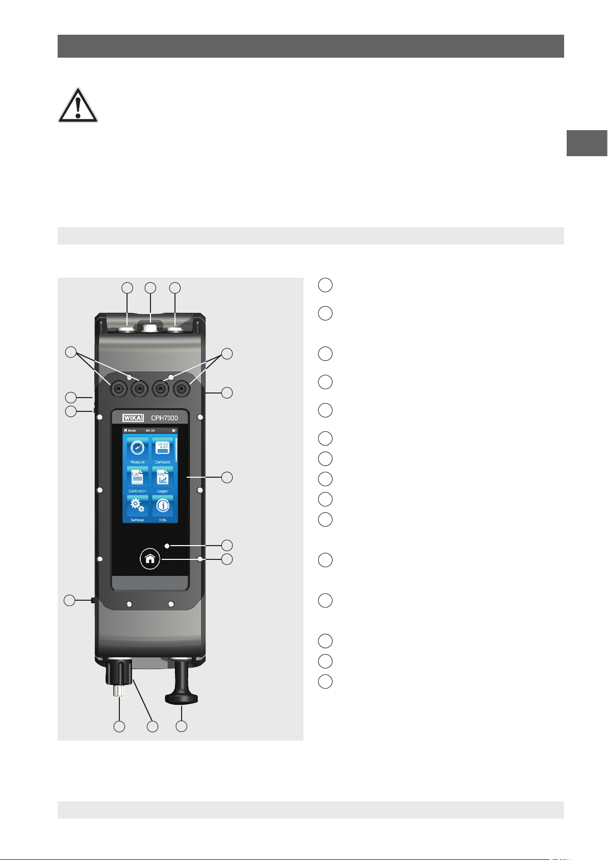
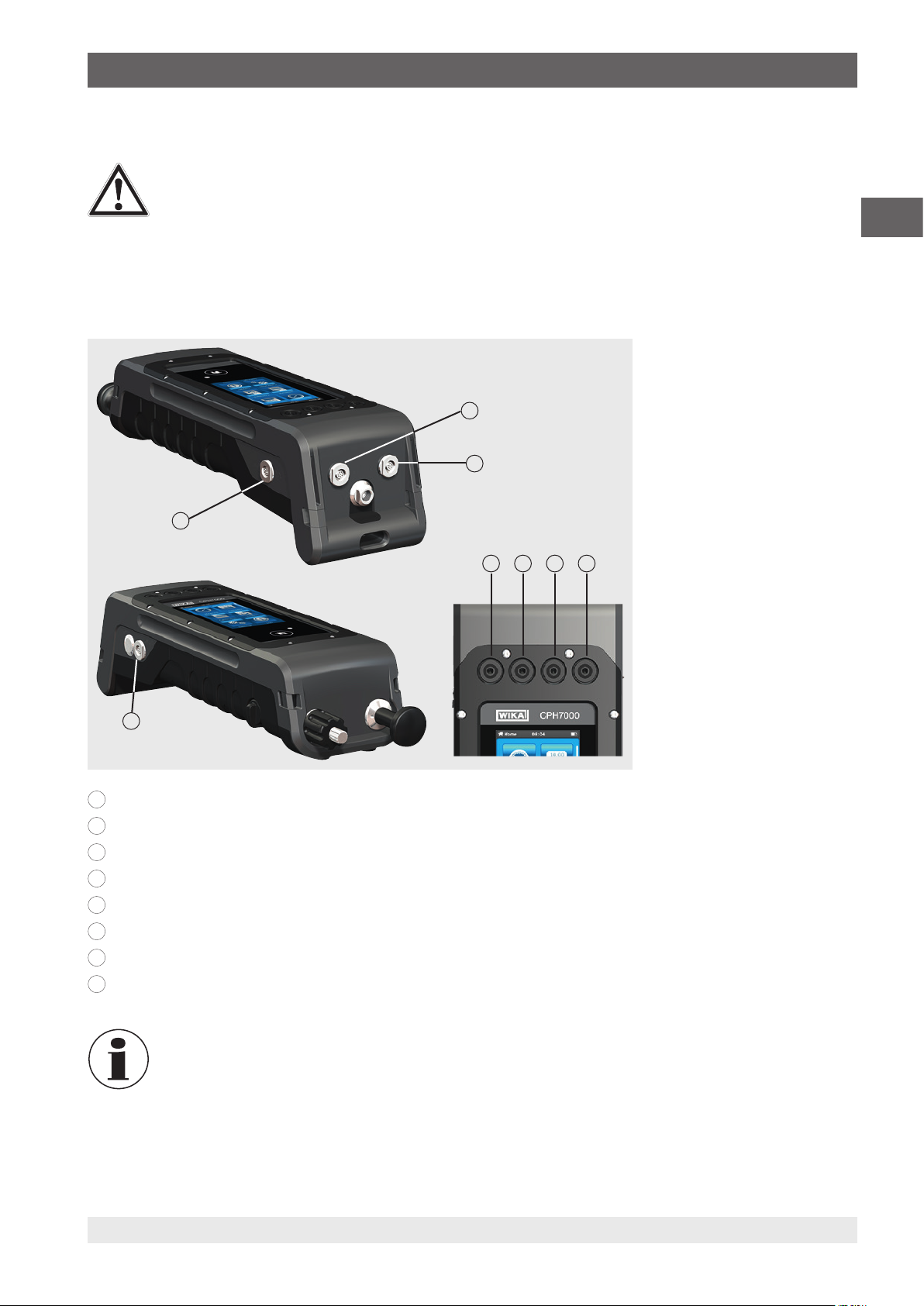
2.1 Overview
1 2 3
15
14
13
4
5
1
2
3
4
5
6
EN
Connection for external pressure sensor - channel 1
(only CPT7000)
Internal sensor for test item
(optional, available only in conjunction with the
mechanical hand pump)
Connection for external pressure sensor - channel 2
(only CPT7000)
Sockets for 4 mm plugs for measuring and simulating
current (DC)
Connection for atmospheric module or temperature
probe Pt100
Display
7
LED charging indicator
6
8
Home button
9
Mechanical hand pump (optional)
10
Fine adjustment valve
(optional, available only in conjunction with the
7
8
mechanical hand pump)
11
Vent valve
(optional, available only in conjunction with the
mechanical hand pump)
12
12
Switch to switch between pressure build-up or vacuum
(optional, available only in conjunction with the
mechanical hand pump)
13
Connection for power supply unit
14
ON/OFF key
15
Sockets for 4 mm plugs for measuring and simulating
voltages (DC)
11 10
9
14204467.02 03/2019 EN/DE
WIKA operating instructions portable process calibrator, model CPH7000 7
Page 8

2. Short overview / 3. Safety
2.2 Description
The model CPH7000 process calibrator is a battery-powered, precise, portable calibrator for the on-site calibration and
checking of analogue pressure measuring instruments, pressure transmitters and process transmitters. Furthermore, pressure
switches can be checked and the switch point determined. With the CPH7000, not only can transmitters be checked, but also
simulated and tested.
EN
The integrated hand pump (optional) enables you to generate a pressure of up to 25 bar (360 psi). This pressure can be
measured by means of an integrated pressure sensor (optional, available only in conjunction with the pump).
For pressure ranges of -1 ... 10,000 bar (-14.5 ... 145,000 psi), the model CPT7000 external precision pressure transmitter is
available. In conjunction with the data logger, it is also possible to carry out a leakage test in a very simple manner.
2.3 Scope of delivery
■
Process calibrator model CPH7000
■
Power supply unit
■
Operating instructions
■
Service case with 2 connection cables (4 mm plugs)
■
Calibration certificate
Cross-check scope of delivery with delivery note.
2.4 Product passport
The product passport can be retrieved from the product page or directly from the corresponding web application (https://portal.
wika.com/serial/).
3. Safety
3.1 Explanation of symbols
DANGER!
... indicates a directly dangerous situation resulting in serious injury or death, if not avoided.
WARNING!
... indicates a potentially dangerous situation that can result in serious injury or death, if not avoided.
CAUTION!
... indicates a potentially dangerous situation that can result in light injuries or damage to property or the
environment, if not avoided.
DANGER!
... identifies hazards caused by electrical power. Should the safety instructions not be observed, there is a risk of
serious or fatal injury.
Information
... points out useful tips, recommendations and information for efficient and trouble-free operation.
8 WIKA operating instructions portable process calibrator, model CPH7000
14204467.02 03/2019 EN/DE
Page 9
3. Safety
3.2 Intended use
The model CPH7000 process calibrator is a portable multi-function calibrator for the calibration of a variety of measuring
instruments. An integrated mechanical hand pump (optional) enables you to generate pressures up to 25 bar (360 psi); an
integrated electrical module also enables you to supply transmitters or sensors with a current of max. 30 mA (voltage (idling) =
DC 24 V), in addition to the typical measurement of current and voltage signals.
The process calibrator can be used to carry out and document a complete calibration process. In addition to the functions
of displaying, measuring and calibrating, the functions logging and switch test are also available. The use of the WIKA-Cal
software also allows a complete documentation.
The instrument has been designed and built solely for the intended use described here, and may only be used accordingly.
The technical specifications contained in these operating instructions must be observed. Improper handling or operation of the
instrument outside of its technical specifications requires the instrument to be taken out of service immediately and inspected
by an authorised WIKA service engineer.
Handle electronic precision measuring instruments with the required care (protect from humidity, impacts, strong magnetic
fields, static electricity and extreme temperatures, do not insert any objects into the instrument or its openings). Plugs and
sockets must be protected from contamination.
The manufacturer shall not be liable for claims of any type based on operation contrary to the intended use.
EN
3.3 Improper use
DANGER!
Danger to life from explosion!
Improper use of the process calibrator causes a risk of explosion that can result in death.
WARNING!
Injuries, material and environmental damage due to an improper use of the process calibrator!
Improper use of the process calibrator causes a direct danger to life.
WARNING!
Injuries through improper use
Improper use of the instrument can lead to hazardous situations and injuries.
14204467.02 03/2019 EN/DE
▶
The process calibrator should not be thrown into fire, since the built-in battery can explode.
▶
Do not throw the process calibrator into water → this can result in the destruction of the safety circuit, in heat
generation, in inflammation, in the formation of oxyhydrogen or corrosion and in the generation of electrolytes.
▶
Overcharging, reverse charging and too high charging currents can result in fire or excessive gas formation.
▶
The use of incorrect, unsuitable power supply units can lead to overheating, fire and to the destruction of the
rechargeable battery.
▶
Crushing due to mechanical damage may result in the escape of electrolytes, in an internal short circuit, in
heating or fire.
▶
Refrain from unauthorised modifications to the instrument.
▶
Do not use the instrument within hazardous areas.
▶
There must be no external pressure acting on the CPH7000.
▶
Do not use the CPT7000 with abrasive or viscous media.
▶
Only dry, clean air can be used as medium for the CPH7000.
▶
It is forbidden to open the instrument.
▶
Do not open the service flap on the rear. Only the manufacturer is allowed to open it.
▶
Do not apply a voltage greater than the specified voltage to the instrument. See chapter 10 “Specifications”.
▶
Make sure that the test probes never contact a voltage source while the test leads are connected to the
terminals.
▶
Do not use the CPH7000 if it is damaged. Before using the process calibrator, check that there are no cracks
or missing plastic parts on the case. Pay particular attention to the insulation of the connectors.
▶
Select the proper function and correct measuring range for the measurement.
WIKA operating instructions portable process calibrator, model CPH7000 9
Page 10
EN
3. Safety
▶
When using the electrical module, set the measurement type first and then connect the connection cables.
▶
Only tighten the vent valve by hand, as it is a needle valve. Tightening with excessive force can result in a
damage of the needle valve or the sealing.
▶
Inspect the test leads for damaged insulation or exposed metal. Check the continuity of the leads. Damaged
test leads should be replaced before using the process calibrator.
▶
When using test probes, keep fingers away from the test probe contacts. Keep your fingers behind the test
probes' finger guards.
▶
First connect the common lead, and then the live lead. When disconnecting, remove the live test lead first.
▶
Disconnect test leads before changing to another measurement or source function.
▶
When the battery indicator lights up red, load the rechargeable battery of the CPH7000, in order to avoid an
incorrect display or a data loss.
▶
To avoid any damage to the process calibrator or to the inspection equipment, always use the proper
connection cable, function and area for the respective measuring application.
▶
The switch valve can be switched from positive pressure to vacuum or from vacuum to positive pressure only
in depressurized state.
▶
Only use the accessories specified and authorized by WIKA.
▶
If pressure is applied over a long period of time, the pump can be damaged.
▶
Only use pressure sensors model CPT7000! The use of other pressure sensors can result in the destruction of
the measuring instrument and of the pressure sensor.
▶
Make sure that the internal sensor is not overloaded by the pump.
The electrical module can generate max. 30 mA and DC 24 V and measure max. 30 mA and DC 30 V.
With the integrated pump, pressures from -0.85 ... +25 bar (-12.3 ... +360 psi) can be generated.
Any use beyond or different to the intended use is considered as improper use.
3.4 Responsibility of the operator
The instrument is used in the industrial sector. The operator is therefore responsible for legal obligations regarding safety at
work.
The safety instructions within these operating instructions, as well as the safety, accident prevention and environmental
protection regulations for the application area must be maintained.
The operator is obliged to maintain the product label in a legible condition.
3.5 Personnel qualification
WARNING!
Risk of injury should qualification be insufficient
Improper handling can result in considerable injury and damage to equipment.
▶
The activities described in these operating instructions may only be carried out by skilled personnel who have
the qualifications described below.
Skilled personnel
Skilled personnel, authorised by the operator, are understood to be personnel who, based on their technical training,
knowledge of measurement and control technology and on their experience and knowledge of country-specific regulations,
current standards and directives, are capable of carrying out the work described and independently recognising potential
hazards.
Special operating conditions require further appropriate knowledge, e.g. of aggressive media.
10 WIKA operating instructions portable process calibrator, model CPH7000
14204467.02 03/2019 EN/DE
Page 11
3. Safety
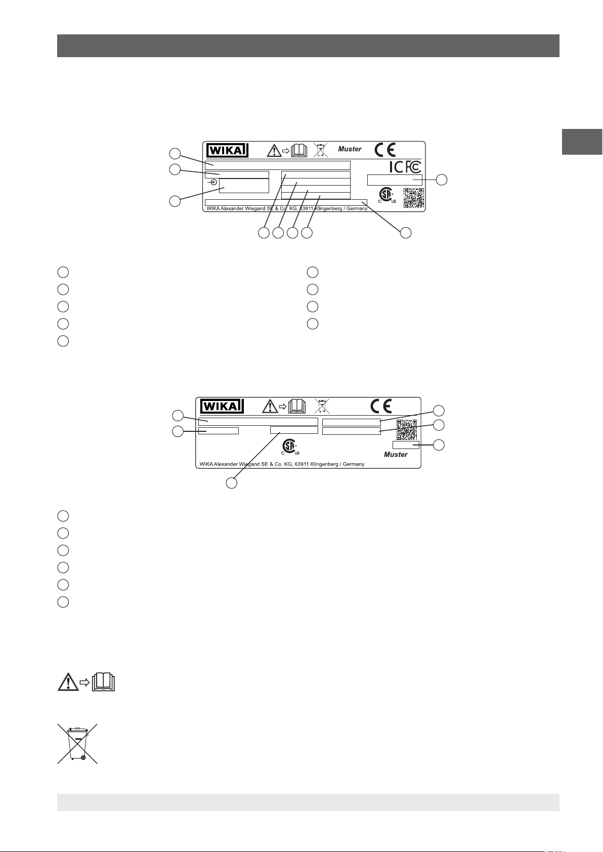
3.6 Labelling, safety marks
3.6.1 Product label for process calibrator model CPH7000
The product label is located on the rear, in the upper part.
9
8
7
1
Approval-related data for radio approval
2
Safety instructions for radio approval
3
Permissible ambient temperature
4
Serial number
5
Date of manufacture (month-year)
6
Accuracy
7
Input signals
8
Pressure measuring range
9
Model
3.6.2 Product label for reference pressure sensor model CPT7000
6
5
EN
1
256 4 3
1
2
3
1
Serial number
2
Serial number external sensor
3
Date of manufacture (month-year)
4
Accuracy
5
Pressure measuring range
6
Model
Symbols
Do not dispose of with household waste. Ensure a proper disposal in accordance with national regulations.
14204467.02 03/2019 EN/DE
4
Before mounting and commissioning the instrument, ensure you read the operating instructions!
WIKA operating instructions portable process calibrator, model CPH7000 11
Page 12

4. Design and function
4. Design and function
The model CPH7000 process calibrator is a battery-powered, precise, portable calibrator for the on-site calibration and
checking of analogue pressure measuring instruments, pressure transmitters and process transmitters. Furthermore, pressure
switches can be checked and the switch point determined. With the CPH7000, not only can transmitters be checked, but also
EN
simulated and tested.
The CPH7000 can be operated by means of a clearly structured touchscreen. The integrated rechargeable battery allows the
CPH7000 to be used daily in the field.
4.1 Design
The CPH7000 can optionally be equipped with an integrated reference pressure sensor as well as an integrated manual
pressure generation (pressure sensor only available in conjunction with pressure generation), with which pressures from
-0.85 ... +25 bar (-12.3 ... +360 psi) can be generated.
A pressure connection enables a calibration item (test item) to be connected to the reference pressure sensor as well as to
the integrated pressure generation of the CPH7000. The integrated pump (optional) allows you to generate different pressure
ratings and thus to carry out a calibration.
An external separate pressure generation up to 25 bar (360 psi) is thus not necessary.
Transmitter output signals can simultaneously be measured via an electrical module, thus enabling the simultaneous display
of the reference and test item value on the screen. This allows a complete transmitter calibration to be carried out with just the
CPH7000.
In addition to the integrated sensor, it is also possible to connect up to two external reference pressure sensors to the
CPH7000, thus enabling the measurement of pressure also in other pressure ranges or differential pressure. Communication
between CPH7000 and pressure sensors is digital.
The ambient atmospheric pressure is measured via an integrated barometric reference which can optionally be integrated
in the case. This also enables gauge pressure sensors to be converted into absolute pressure. The ambient conditions
(temperature and humidity) can be measured by means of an additional external atmospheric module. To the connection for
the atmospheric module, it is also possible to connect a temperature probe Pt100.
4.2 Functions and data transfer with the WIKA-Cal calibration software
The calibrator offers the possibility to create calibration routines quickly and easily, but also to carry out preconfigured
calibration routines. An integrated memory allows the recording of logger cycles as well as calibrations on site.
The completed calibration processes can be transmitted to a PC via WIKA-Wireless.
As soon as a connection exists over WIKA-Wireless, it can communicate with the WIKA-Cal calibration software from version
1.0.66. Data can also be transferred using Windows Explorer.
A complete paperless transmitter calibration can be carried out using the CPH7000 and WIKA-Cal.
As the CPH7000 features an electrical module, the hand-held also has to be set up as a multimeter.
Compatibility between the CPH7000 process calibrator and the WIKA-Cal evaluation software is only possible
with the following firmware versions and higher.
CPH7000: 1.1.4 or higher
WIKA-Cal: 1.0.82 or higher
12 WIKA operating instructions portable process calibrator, model CPH7000
14204467.02 03/2019 EN/DE
Page 13
4. Design and function
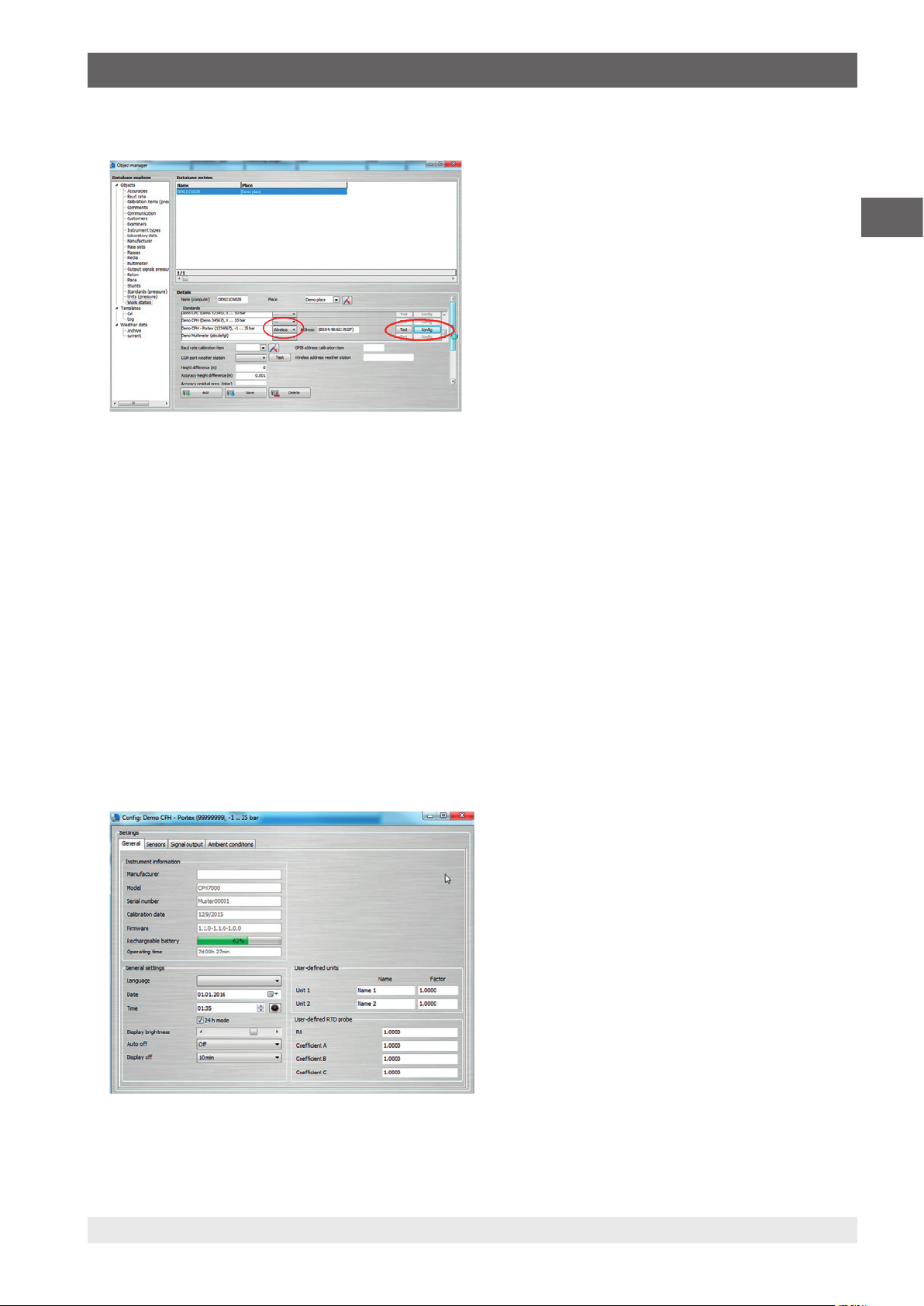
4.2.1 WIKA-Cal configuration (also possible with the demo version)
1. In WIKA-Cal, in the “Object manager”, open the menu item “Workplace”.
The CPH7000 must first be defined as a standard and assigned to the workplace.
⇒
2. Call up the Wireless function.
The Wireless monitor will open.
⇒
3. Click into the address field.
The address will be displayed automatically. If required, correct this.
⇒
The communication is working properly if the pressure value displayed on the instrument is shown after pressing the
⇒
[Test] button.
4. Via [Config], the configuration dialogue for the instrument can be called up.
EN
In the configuration window, the four functions “General information”, “Sensors”, “Signal output” and “Ambient
conditions” are available.
General information
Here are all the general parameters of the CPH7000 used.
Specific pressure units with the associated factor can be set or also specific temperature coefficients entered for the Pt100
probe.
14204467.02 03/2019 EN/DE
WIKA operating instructions portable process calibrator, model CPH7000 13
Page 14
4. Design and function
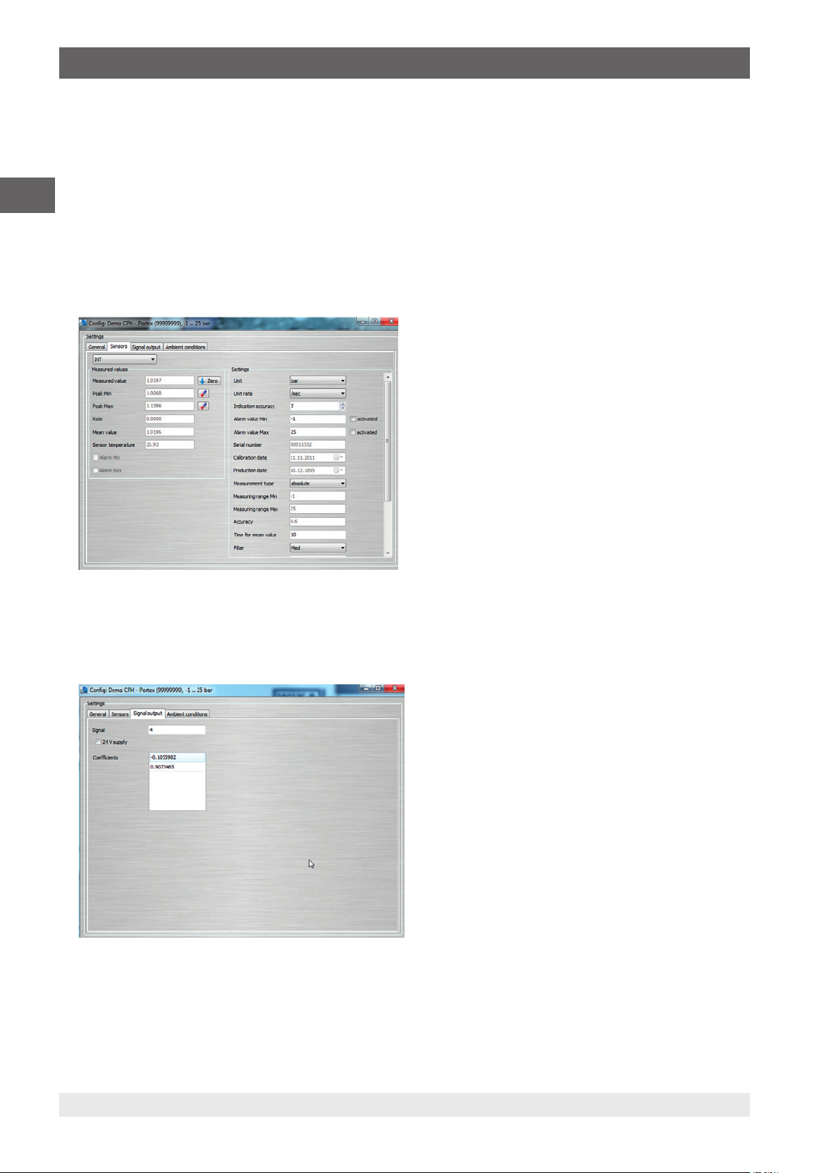
Sensors
The following sensors can be selected:
INT = Internal reference pressure sensor
EN
EXT1 = External CPT7000 reference pressure sensor to channel 1
EXT2 = External CPT7000 reference pressure sensor to channel 2
RTD = External Pt100 temperature probe
IN = Integrated electrical module
EXT1, EXT2 and RTD are only displayed when these are also connected.
Signal output
Here, the current and voltage values can be read in and overwritten. The prerequisite for this is that under “Measure”, a
current or voltage channel has also been selected.
14 WIKA operating instructions portable process calibrator, model CPH7000
14204467.02 03/2019 EN/DE
Page 15
4. Design and function
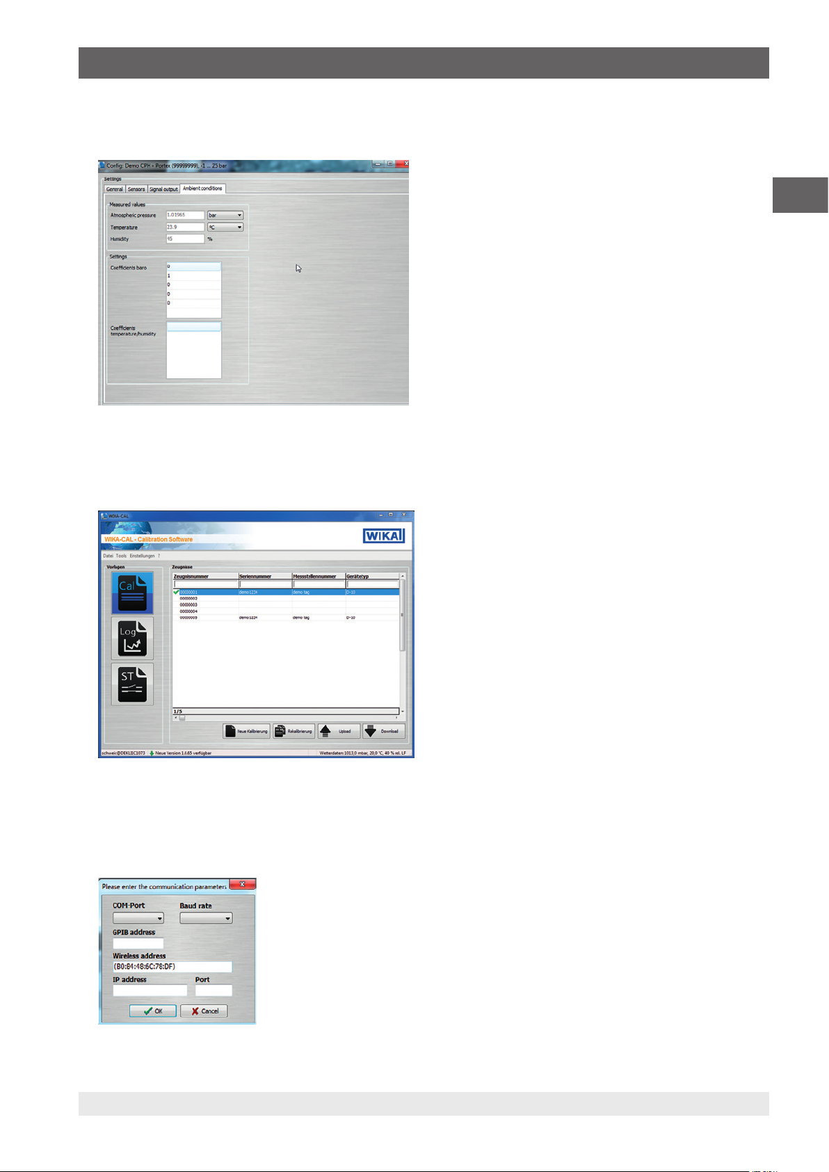
Ambient conditions
Here, the measured values from the atmospheric module and barometer are displayed.
4.2.2 WIKA-Cal - Cal-Template
The following options are available with the “Cal-Template”:
“New calibration”, “Recalibration”, “Upload” and “Download”
EN
New calibration
A new calibration certificate will be created. All parameters from the calibration item and reference instrument must be
entered, and then the calibration can start. By pressing on the “Measuring results” table, a new window opens in which the
communication parameters are requested. Here, the CPH7000 used must be selected, then the measurement starts.
14204467.02 03/2019 EN/DE
WIKA operating instructions portable process calibrator, model CPH7000 15
Page 16
4. Design and function
Recalibration
Select the required certificate from the database. Only completed certificates (marked with a green tick) can be recalibrated. A
copy of the certificate will be created and opened, and when the [Measuring results] table is pressed, the measurement can
be restarted.
EN
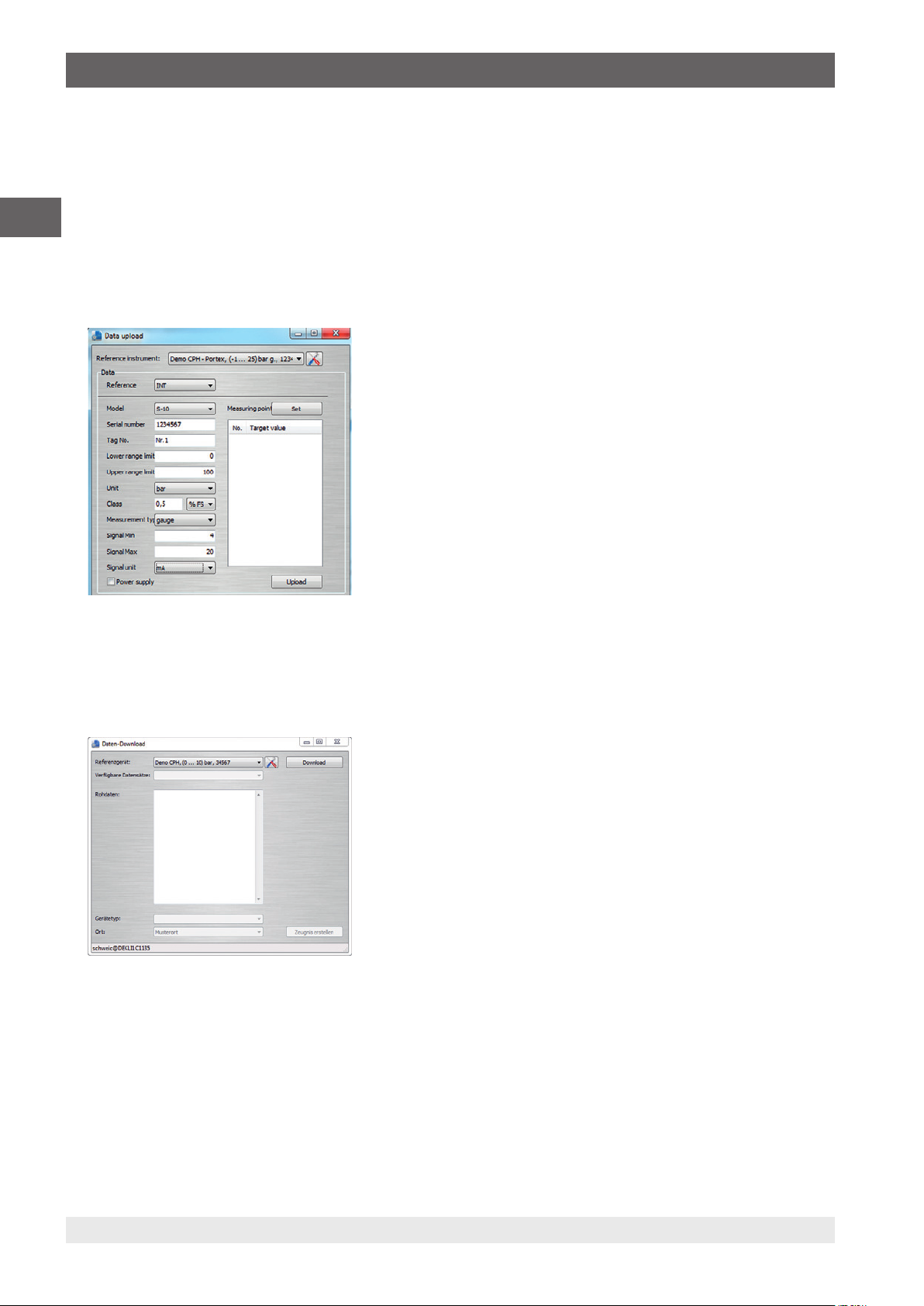
Upload
With “Upload”, a calibration routine can be defined and installed on the CPH7000.
All parameters must be entered. The measuring points and measurement series can be specified by default. With upload, the
calibration routine will be created and uploaded to the CPH7000.
Download
The calibrations stored on the CPH7000 can be downloaded and archived using “Download”.
▶
Select reference instrument and click on “Download”.
Then the available data sets are shown in the selection window.
⇒
4.2.3 WIKA-Cal - Log-Template
The following options are available with the “Log-Template”:
New log
The “New Log” function opens a new logger protocol.
Following the input of all parameters, the “Wireless address” line must be pressed in the communication window. Select the
CPH7000 used and confirm.
By pressing the [Measuring results] graphic, the logger process is started.
14204467.02 03/2019 EN/DE
16 WIKA operating instructions portable process calibrator, model CPH7000
Page 17
4. Design and function
Repeat logging
Similar to “Recalibration”, it is possible to repeat logger sequences.
Download
The logger sequences stored on the CPH7000 can be downloaded and archived using “Download”.
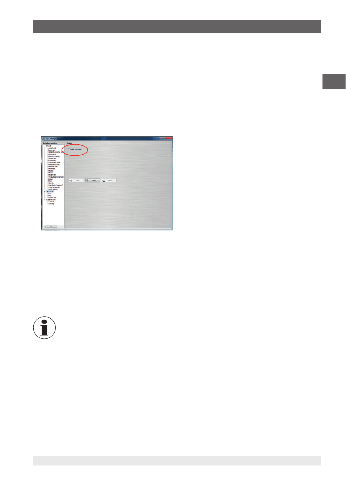
4.2.4 WIKA-Cal - switch test template
Here, only the option “Download” is available:
The switch test procedures stored on the CPH7000 can be downloaded and archived using “Download”.
The switch test function in the WIKA-Cal software has to be activated under “Object manager / Templates”.
EN
When this box is checked, the template for the switch test will appear in the main menu window (see chapter
4.2.2 “WIKA-Cal - Cal-Template”).
4.3 Voltage supply
The internal Lithium-Ion battery, which can be easily charged with the battery charger supplied with the equipment, serves as
the voltage supply for the instrument.
To charge the CPH7000 rechargeable batteries, the mains plug of the power supply unit must always be plugged in to a mains
socket and accessible, so that one can always remove it from the mains socket without difficulty.
When using the electrical module, better results are achieved if the battery is not charged during the
measurement.
To avoid incorrect measurements, recharge the battery as soon as the battery indicator flashes. If the battery discharges too
much, the CPH7000 will automatically turn off.
The battery life is up to 8 hours in continuous operation (without backlighting, WIKA-Wireless is not active and the electrical
module does not supply voltage/current).
In the upper right corner of the display there is a symbol for the battery capacity. For instructions on batteries see chapter
4.10.3 “Battery symbol”).
14204467.02 03/2019 EN/DE
WIKA operating instructions portable process calibrator, model CPH7000 17
Page 18

4. Design and function
4.3.1 Rechargeable battery
The integrated lithium-ion battery is subject to the requirements of the Dangerous Goods Directive. Special
requirements for packaging and labelling must be observed when shipping. A dangerous goods expert must be
consulted when preparing the package.
EN
The rechargeable battery is permanently installed in the model CPH7000 process calibrator.
The battery can be charged only using the power supply unit included in the scope of delivery.
4.3.2 Using the power supply unit
Do not ship the CPH7000 if the rechargeable battery is damaged or defective.
Observe the different dangerous goods requirements relative to the respective modes of transport and any other
national regulations.
DANGER!
Danger to life caused by electric current
Upon contact with live parts, there is a direct danger to life.
▶
Only use the power supply unit from WIKA supplied with the instrument!
▶
If there is any visible damage to the case or the wiring, do not use the power supply unit!
▶
Never install nor store the power supply unit in the following locations, as this can lead to a failure in operation:
■
Places where there is strong humidity or condensation
■
Outdoors
▶
Disconnect the power supply unit from the mains supply when it won’t be used for a longer period of time.
▶
The power supply unit is maintenance-free. It must not be opened (danger of electrical shock).
▶
Before cleaning, disconnect the power supply unit from the mains supply. Do not clean with chemical cleaning
agents. Only clean with a dry cloth.
▶
The power supply unit may only be used at an ambient temperature of 0 ... 40 °C (32 ... 104 °F) (humidity: up to
90 % relative humidity, non-condensing).
To avoid measurement uncertainties, use the CPH7000 only without a connected power supply unit.
The instrument is delivered with a charge level of 25 ... 50 % and should be fully charged once before being used.
The battery capacity status (charge state in %) is displayed shortly after the instrument is switched on.
When the power supply unit is connected to the CPH7000, the battery will be charged, even if the CPH7000 is
switched off.
The typical charging time of the rechargeable battery is < 5 h.
■
When the power supply unit is no longer being used, the mains plug should be disconnected from the mains socket. Do not
leave the rechargeable battery connected to the power supply unit for longer than one day, since overcharging can shorten
its service life.
■
Should the rechargeable battery still not be fully charged after 24 hours, contact the manufacturer. When not being used, a
fully charged battery will lose its charge over time.
■
Extreme temperatures have an adverse effect on battery charging. As a result, the battery may first need to be either cooled
or warmed, as appropriate.
■
When the battery is almost completely discharged, the message “low BAT” appears in the display. To avoid a data loss, the
instrument must be charged immediately.
18 WIKA operating instructions portable process calibrator, model CPH7000
14204467.02 03/2019 EN/DE
Page 19
4. Design and function
4.3.3 During charging
WARNING!
Physical injuries and damage to property and the environment
The temperature range over which the Lithium-Ion battery can be charged is 0 ... 40 °C (32 ... 104 °F).
▶
Do not charge the lithium-ion battery outside this temperature range. This may result in heating or demolition.
In addition, the performance of the Lithium-Ion battery can be affected and the service life reduced.
4.4 Electrical connections
3
EN
2
1
5 6 7 8
4
1
Connection for external pressure sensor model CPT7000 to channel 1 (EXT 1)
2
Connection for external pressure sensor model CPT7000 to channel 2 (EXT 2)
3
Connection for atmospheric module (AMB) or temperature probe Pt100 (RTD)
4
Connection for power supply unit
5
V
- Sockets for 4 mm plugs: Connection for DC 24 V supply
out
6
V
- Sockets for 4 mm plugs: Connection for measuring voltages (DC 30 V) (V_IN)
in
7
mA - Sockets for 4 mm plugs: Connection for measuring and simulating current (30 mA) (mA)
8
GND - Ground connection (GND)
Any external circuit connected to this instrument must be protected against electrical shock by additional
insulation or insulation enhanced against potentially dangerous active voltages.
14204467.02 03/2019 EN/DE
WIKA operating instructions portable process calibrator, model CPH7000 19
Page 20
4. Design and function
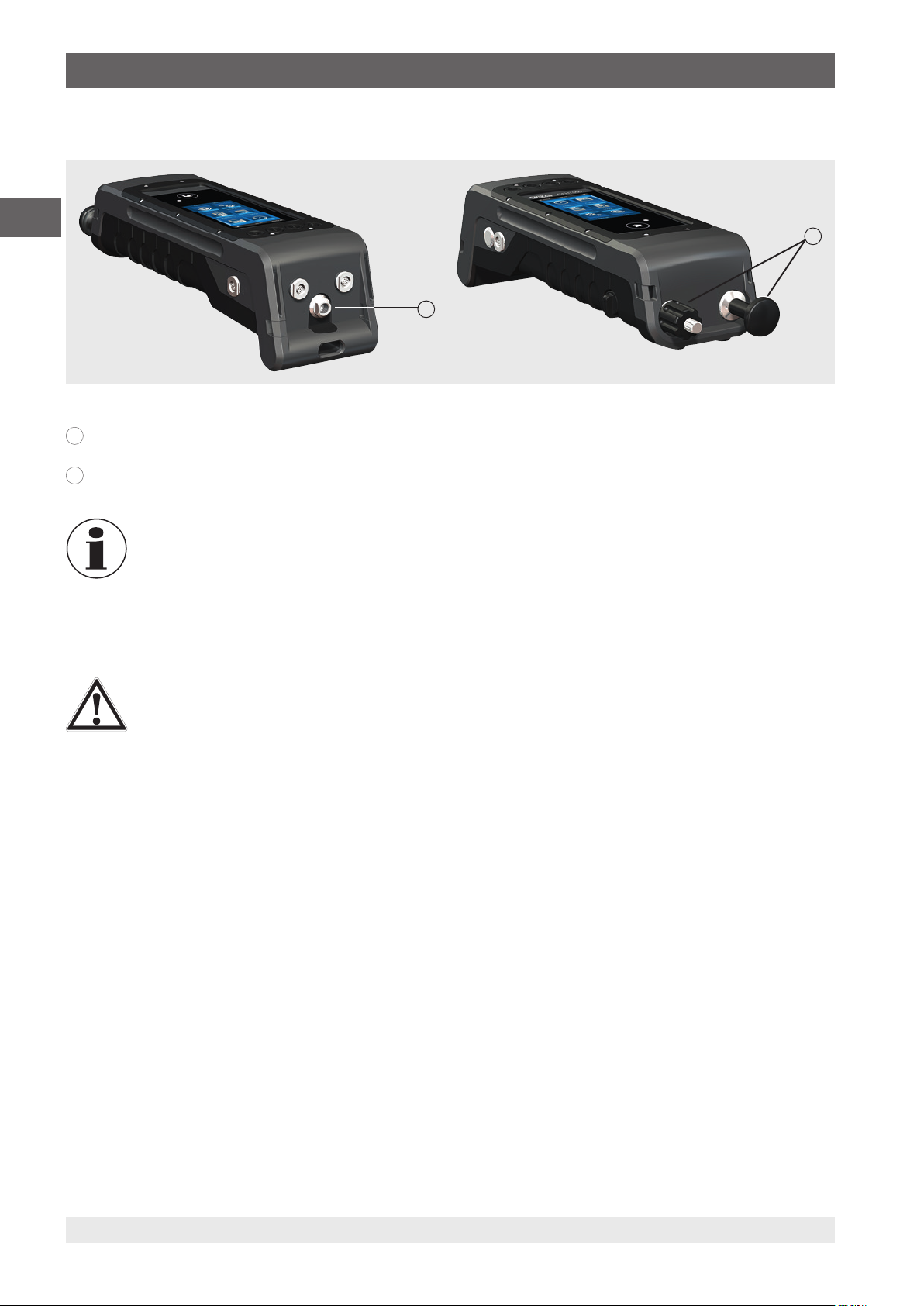
4.5 Mechanical connection
EN
9
G 1/8 female thread
9
Optionally, it can be used only in conjunction with the hand pump (INT).
10
Pumping unit
In order not to put a strain on the case, it is recommended to hold the pressure connection on the CPH7000 by
means of an open-ended spanner.
The connections of the CPH7000 without pumping unit are provided with plugs. In order to maintain the IP
protection class, these plugs should not be removed.
4.6 Pump
10
CAUTION!
Physical injuries and damage to property and the environment
Improper handling of the pump can damage the process calibrator.
▶
Do not use the pump when switched off.
The pump is a consumable. Regular maintenance is recommended after 100,000 pump cycles at the latest. Under normal use
conditions, this corresponds to a service life of 2 years.
Recommended procedure in vacuum range
1. Always pull out the piston rod until it stops.
2. Wait 5 seconds.
3. Carry out another pumping stroke until the desired pressure is reached.
4.7 Barometer
The barometric sensor is a very stable, high-accuracy absolute pressure sensor designed to measure the daily atmospheric
pressure.
It can be used to emulate gauge pressure using an absolute pressure sensor or to emulate absolute pressure using a gauge
pressure sensor. For a seamless absolute pressure emulation, a bi-directional measuring range with a start of measuring
range of -1 bar (-14.5 psi) is recommended.
4.8 Reference pressure sensor model CPT7000
For the CPH7000 process calibrator, a variety of reference pressure sensors with measuring ranges from 250 mbar (4 psi) up
to 10,000 bar (145,000 psi) and vacuum pressure sensors with an accuracy of 0.025 % FS are available. These sensors can
be replaced on the instrument very quickly and without using any tools.
When the process calibrator is switched on, the connected reference pressure sensor will be automatically detected.
14204467.02 03/2019 EN/DE
20 WIKA operating instructions portable process calibrator, model CPH7000
Page 21
4. Design and function
4.8.1 Connection of the model CPT7000 reference pressure sensor
CAUTION!
Physical injuries and damage to property and the environment
If third-party reference pressure sensors are used, they can damage the process calibrator and the reference
pressure sensor.
▶
Only use reference pressure sensors of model CPT7000!
▶
When the CPH7000 is switched on, the model CPT7000 reference pressure sensor must be mounted in the
position in which the measurements will be made and must not be under pressure, but rather should be at
atmospheric pressure.
▶
Only ever use the original WIKA connection cable in the operation of CPT7000 reference pressure sensors.
4.8.2 Electrical connection of the CPT7000 reference pressure sensor to the CPH7000
To electrically connect a model CPT7000 reference pressure sensor, the corresponding plug connection of the cable at the
sensor must be plugged in.
To disconnect the sensor, do not pull on the cable, but rather only on the connector sleeve.
To connect it to the CPH7000, the other end of the cable must also be plugged in. To disconnect the CPH7000, do not pull on
the cable, but rather only on the connector sleeve.
EN
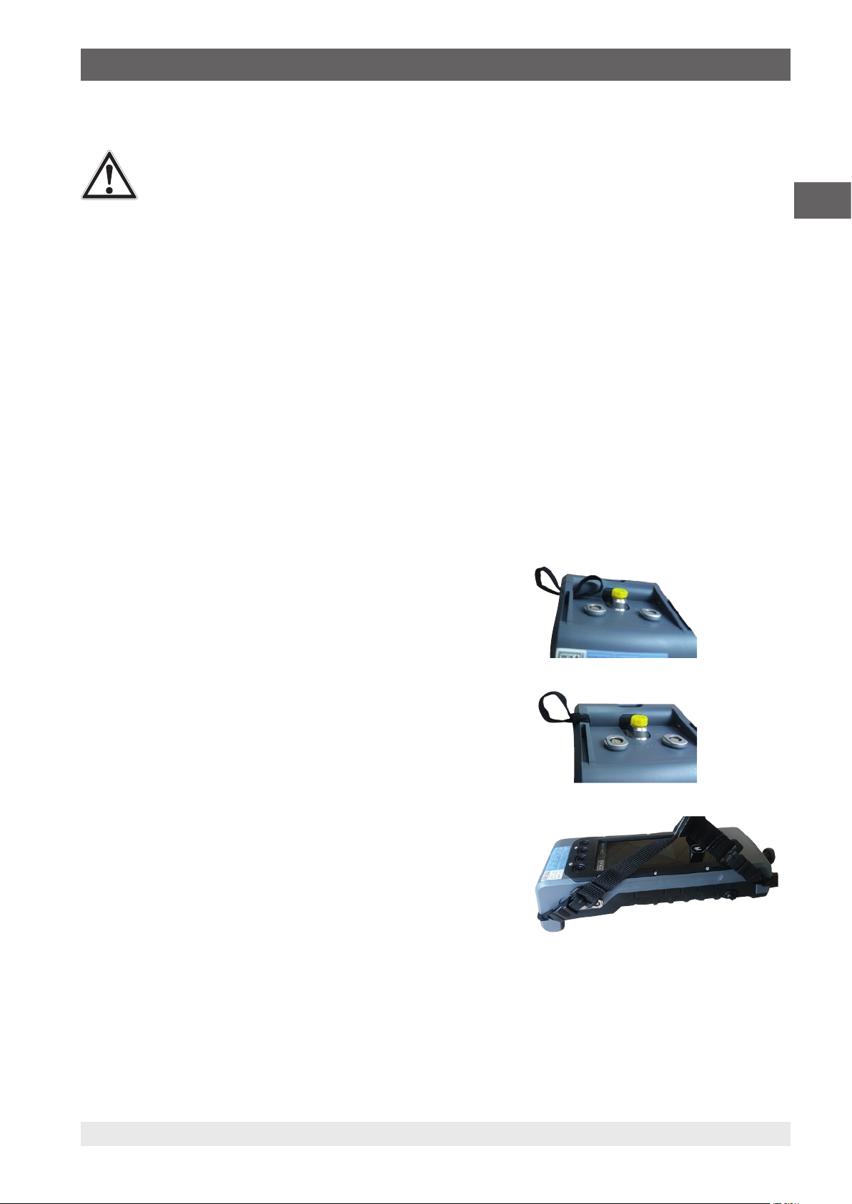
4.9 Carrying system
For safely carrying the CPH7000, the associated shoulder strap can be put on.
Recommended procedure for putting on the shoulder strap:
1. Pull the enclosed loops through the eyelets of the CPH7000, see figure 1.
2. Thread the loop, see figure 2.
3. Fasten the hooks of the shoulder strap, see figure 3.
Recommendation:
Fasten the long belt to the top corners of the CPH7000 and the short belt to
the bottom ones.
Figure 1
Figure 2
Figure 3
14204467.02 03/2019 EN/DE
WIKA operating instructions portable process calibrator, model CPH7000 21
Page 22
EN
4. Design and function
4.10 Display
11
18
27
10
6
3
4
5
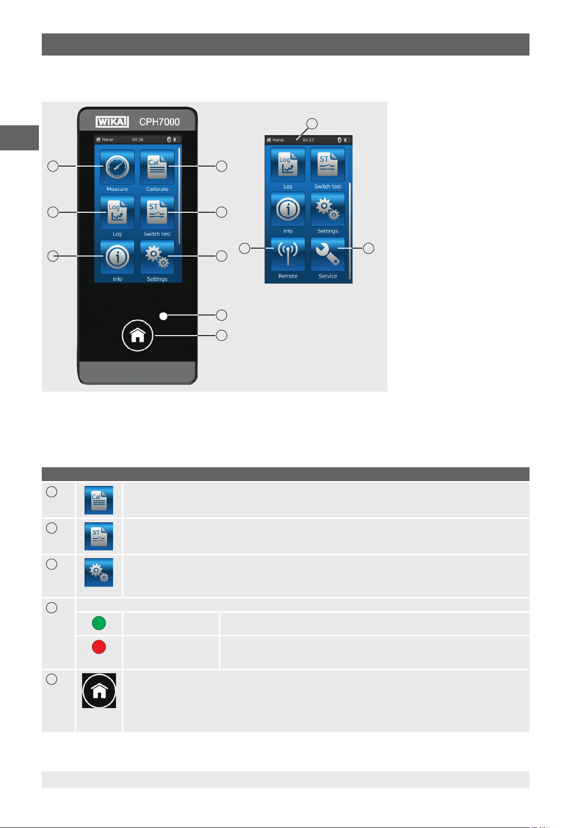
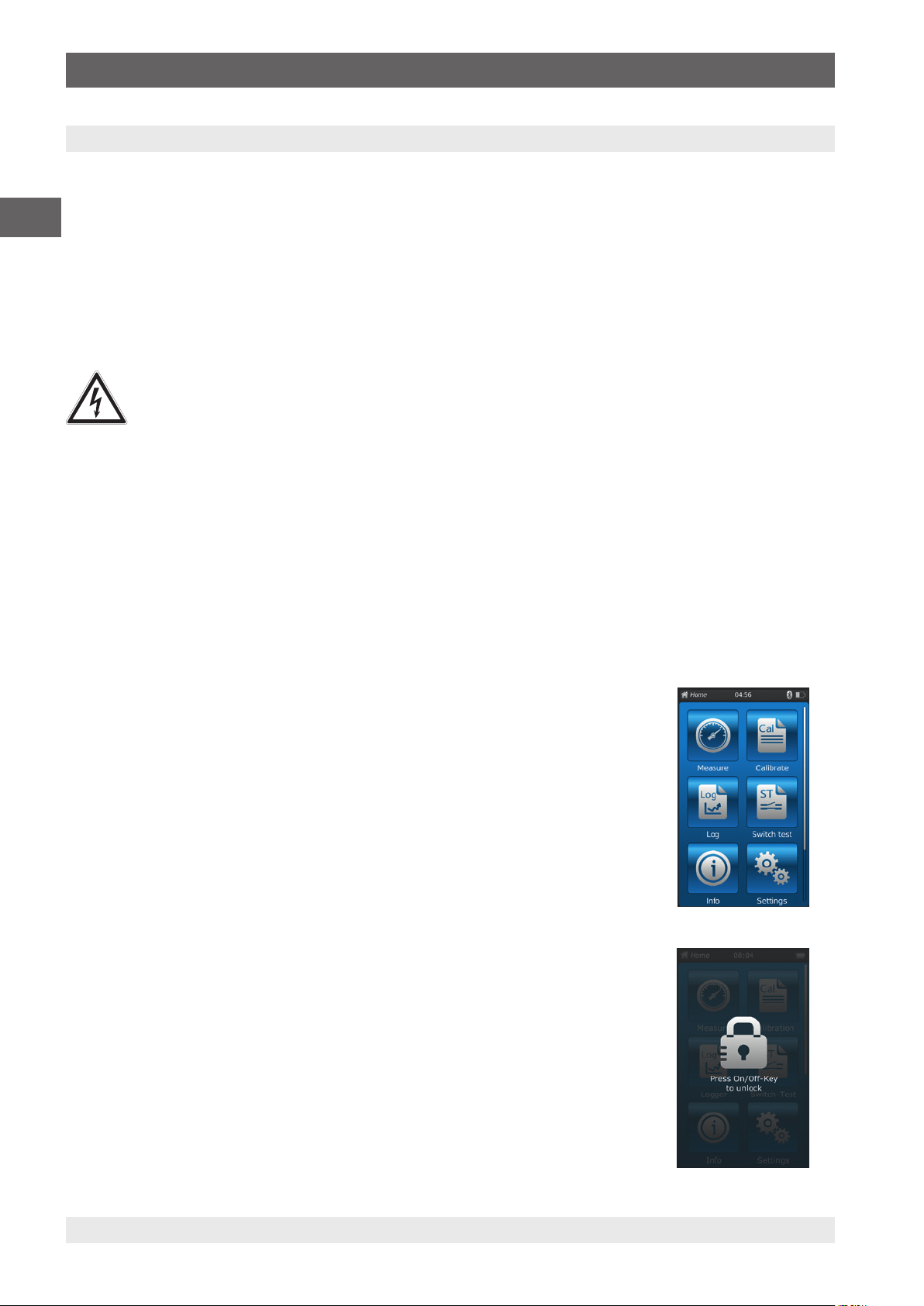
4.10.1 Applications (apps)
Eight applications are available on the start page:
Measure, Calibrate, Logger, Switch test, Info, Settings, Remote and Service.
Pos. Symbol
1
2
Calibration
Opens the [Calibrate] application, see chapter 6.4 “Calibrate”
Switch test
Opens the [Switch test] application, see chapter 6.6 “Switch test”
9
3
Settings
Setting or changing of all instrument parameters, such as: Language, date, time, display brightness, pressure units
and temperature probes
For more information please refer to chapter 6.2.2 “Application [Settings]”.
4
LED display
■
LED lights up green:
■
LED flashes green:
■
LED lights up red:
■
LED flashes red:
The rechargeable battery is fully charged
CPH7000 in start mode
The rechargeable battery is being charged
Charging error
⇒ Remove the charging cable and reconnect it to the CPH7000
5
Home
Use the [Home] button to go to the start page.
If the [Home] button is held pressed for more than 2.5 seconds, a screenshot with the file name “YYYYMMDD_
hhmmss-Screenshot.png” 1) will be created. This file can be readout via WIKA-Wireless.
The CPH7000 can store a maximum of 50 screenshots; if more than 50 screenshots are created, the first ones will
be overwritten.
1) An instructions for downloading the screenshots are available on request.
22 WIKA operating instructions portable process calibrator, model CPH7000
14204467.02 03/2019 EN/DE
Page 23
4. Design and function
Pos. Symbol
6
7
Info
To call all information on the CPH7000, including all connected internal and external sensors, see chapter
6.2.3 “Application [Info]”.
Logger
Opens the [Logger] application, see chapter 6.5 “Logger”.
EN
8
9
10
Measure
Opens the [Measure] application. Three channels can be simultaneously selected and displayed. See chapter
6.3 “Measure”.
Service
Display of all service-relevant data of the connected sensors and of current error messages, see chapter
6.2.5 “Application [Service]”.
Remote
Display of the communication commands and parameters
Switching on or off the WIKA-Wireless interface, see chapter 6.2.4 “Application [Remote]”.
Further definitions
“XXX” Menu XXX will be selected
[XXX] Press button XXX
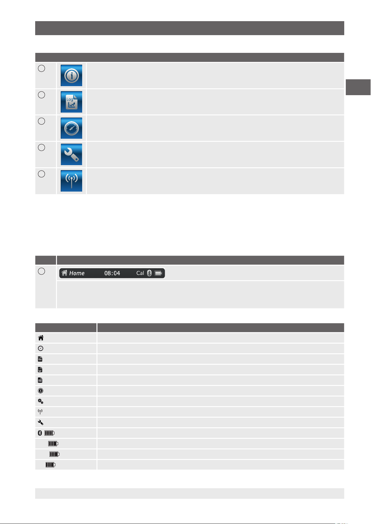
4.10.2 Symbols of the status bar
Pos. Symbol
11
The status bar is located at the top of the screen.
■
Left: Display of the selected function page
■
Middle: Display of the currently set time
■
Right: Display of the activated function and battery status
Symbol The symbol lights up on:
Home
Measure
Calibrate
Logger
Switch test
Info
Settings
Remote
Service
Cal
Log
St
14204467.02 03/2019 EN/DE
Start screen activated
Application [Measure] activated
Application [Calibrate] activated
Application [Logger] activated
Application [Switch test] activated
Application [Info] activated
Application [Settings] activated
Application [Remote] activated
Application [Service] activated
WIKA-Wireless switched on
Calibration switched on
Logger switched on
Switch test switched on
WIKA operating instructions portable process calibrator, model CPH7000 23
Page 24
4. Design and function / 5. Transport, packaging and storage
Symbol The symbol lights up on:
Cal
Log
EN
St
Cal
Log
St
Cal
Log
St
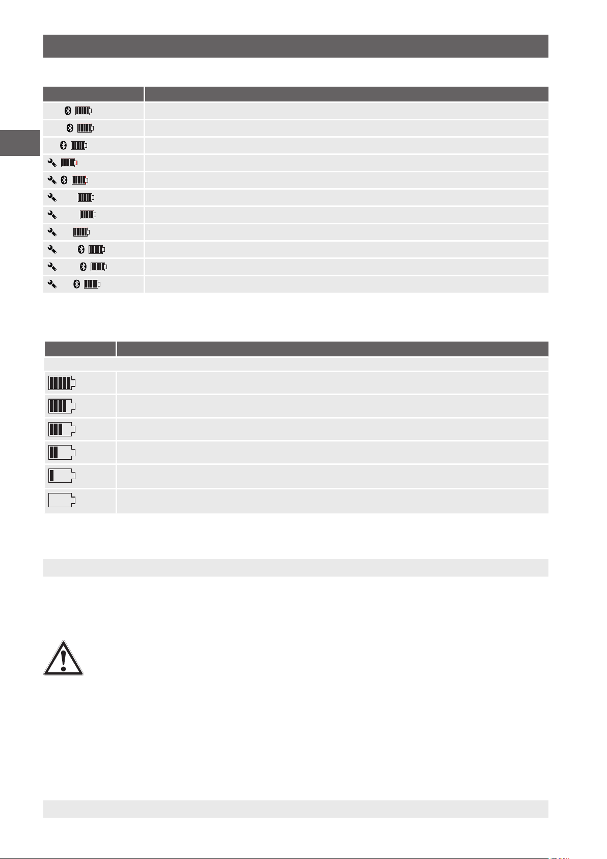
4.10.3 Battery symbol
Calibration started and WIKA-Wireless active
Logger started and WIKA-Wireless active
Switch test started and WIKA-Wireless active
Request: Open the [Service] app
Request: Open the [Service] app and WIKA-Wireless active
Request: Open the [Service] app and calibration active
Request: Open the [Service] app and logger active
Request: Open the [Service] app and switch test active
Request: Open the [Service] app, calibration and WIKA-Wireless active
Request: Open the [Service] app, logger and WIKA-Wireless active
Request: Open the [Service] app, switch test and WIKA-Wireless active
Symbol The symbol lights up on:
The battery symbol is lit continuously and is dependent upon the current battery status.
Battery status 100 %
Battery status 80 %
Battery status 60 %
Battery status 40 %
Battery status 20 %
Charge the battery
⇒
Battery status 0 %
Charge the battery immediately
⇒
5. Transport, packaging and storage
5.1 Transport
Check the instrument for any damage that may have been caused by transport.
Obvious damage must be reported immediately.
CAUTION!
Damage through improper transport
With improper transport, a high level of damage to property can occur.
▶
When unloading packed goods upon delivery as well as during internal transport, proceed carefully and
observe the symbols on the packaging.
▶
With internal transport, observe the instructions in chapter 5.2 “Packaging and storage”.
If the instrument is transported from a cold into a warm environment, the formation of condensation may result in instrument
malfunction. Before putting it back into operation, wait for the instrument temperature and the room temperature to equalise.
24 WIKA operating instructions portable process calibrator, model CPH7000
14204467.02 03/2019 EN/DE
Page 25

5. Transport, packaging and storage
5.2 Packaging and storage
The process calibrator CPH7000 is delivered in a plastic case. This will provide optimum protection during transport (e.g.
change in installation site, recalibration).
Permissible conditions at the place of storage:
Process calibrator
model CPH7000
Storage temperature -20 ... +60 °C (-4 ... +140 °F) -20 ... +80 °C (-4 ... +176 °F) -40 ... +70 °C (-40 ... +158 °F)
Humidity 35 ... 85 % relative humidity
(non-condensing)
Reference pressure sensor
model CPT7000
0 ... 95 % relative humidity
(non-condensing)
Power supply unit
model FW7530
20 ... 80 % relative humidity
(non-condensing)
Avoid exposure to the following factors:
■
Direct sunlight or proximity to hot objects
■
Mechanical vibration, mechanical shock (putting it down hard)
■
Soot, vapour, dust and corrosive gases
■
Hazardous environments, flammable atmospheres
Store the process calibrator in the supplied plastic case in a location that fulfils the conditions listed above.
Fully charge the CPH7000 (to avoid deep discharge of the rechargeable battery)
5.3 Rechargeable battery
The integrated lithium-ion battery is subject to the requirements of the Dangerous Goods Directive. Special
requirements for packaging and labelling must be observed when shipping. A dangerous goods expert must be
consulted when preparing the package.
Do not ship the CPH7000 if the rechargeable battery is damaged or defective.
Observe the different dangerous goods requirements relative to the respective modes of transport and any other
national regulations.
EN
The rechargeable battery is permanently installed in the model CPH7000 process calibrator. In case the battery in the process
calibrator stops working, contact the manufacturer.
For contact details see chapter 1 “General information” or the back page of the operating instructions.
▶
Do not throw the instrument into fire.
If the CPH7000 is thrown into fire, the built-in rechargeable battery can explode.
▶
Do not throw the instrument into water.
If the CPH7000 is thrown into water, this can result in the destruction of the safety circuit, in heat generation, in
inflammation, in the formation of oxyhydrogen or corrosion and in the generation of electrolytes.
▶
Overcharging, reverse charging, too high charging currents
Overcharging, reverse charging, too high charging currents and the use of incorrect, unsuitable chargers can lead to
overheating, fire, excessive gas formation and to the destruction of the rechargeable battery.
▶
Crushing, mechanical damage
Crushing can cause the rechargeable battery to be damaged, for example by means of mechanical pressure. This may
result in the escape of electrolytes, in an internal short circuit, and in heating and fire.
▶
Before storing the instrument for a longer time, fully charge the CPH7000, in order to avoid deep discharge of the
rechargeable battery.
14204467.02 03/2019 EN/DE
WIKA operating instructions portable process calibrator, model CPH7000 25
Page 26
6. Commissioning, operation
6. Commissioning, operation
Personnel: Skilled personnel
Only use original parts (see chapter 11 “Accessories”).
EN
Prior to commissioning, check the CPH7000 process calibrator as well as the CPT7000 external pressure transmitter for
integrity.
Only use the calibrator and the reference pressure sensors if they are in perfect condition with respect to safety.
6.1 Electrical mounting
DANGER!
Danger to life caused by electric current
Upon contact with live parts, there is a direct danger to life.
▶
Operation using a defective power supply unit (e.g. short circuit from the mains voltage to the output voltage)
can result in life-threatening voltages at the instrument!
▶
Only use the power supply unit from WIKA supplied with the instrument!
6.2 Operation
The On/Off key is located on the left side of the case. To switch on the instrument, the key must be pressed for approx. 2.5 s
until the LED starts to flash green. As soon as the process calibrator is turned on, it will go through a short self-test routine.
Then the main screen appears. The calibrator requires a warm-up period of about 5 minutes to reach its specified accuracy.
Large changes in ambient temperature may make a longer warm-up period necessary. The pressure sensors should be zeroed
each time the calibrator is started.
6.2.1 ON/OFF key
6.2.1.1 Switching on
1. To switch on the instrument, the On/Off key must be pressed for approx. 2.5 s.
The main screen appears.
⇒
The desired applications can now be started.
⇒
6.2.1.2 Locking the screen
1. To lock the screen, the On/Off key must be pressed briefly.
The locking dialog appears.
⇒
The process calibrator is locked for further entries.
⇒
2. To unlock the screen, press the On/Off key.
Return to the main screen.
⇒
26 WIKA operating instructions portable process calibrator, model CPH7000
14204467.02 03/2019 EN/DE
Page 27
6. Commissioning, operation
6.2.1.3 Switching off
1. To switch off the instrument, press the On/Off key for approx. 2.5 s.
The switching off dialog appears.
⇒
■
Confirm the dialog or press the On/Off key again.
The process calibrator is switched off.
⇒
■
To cancel, press [Home].
Return to the main screen.
⇒
2. To directly switch off the instrument, press the On/Off key for more than 10 s.
The process calibrator is switched off.
⇒
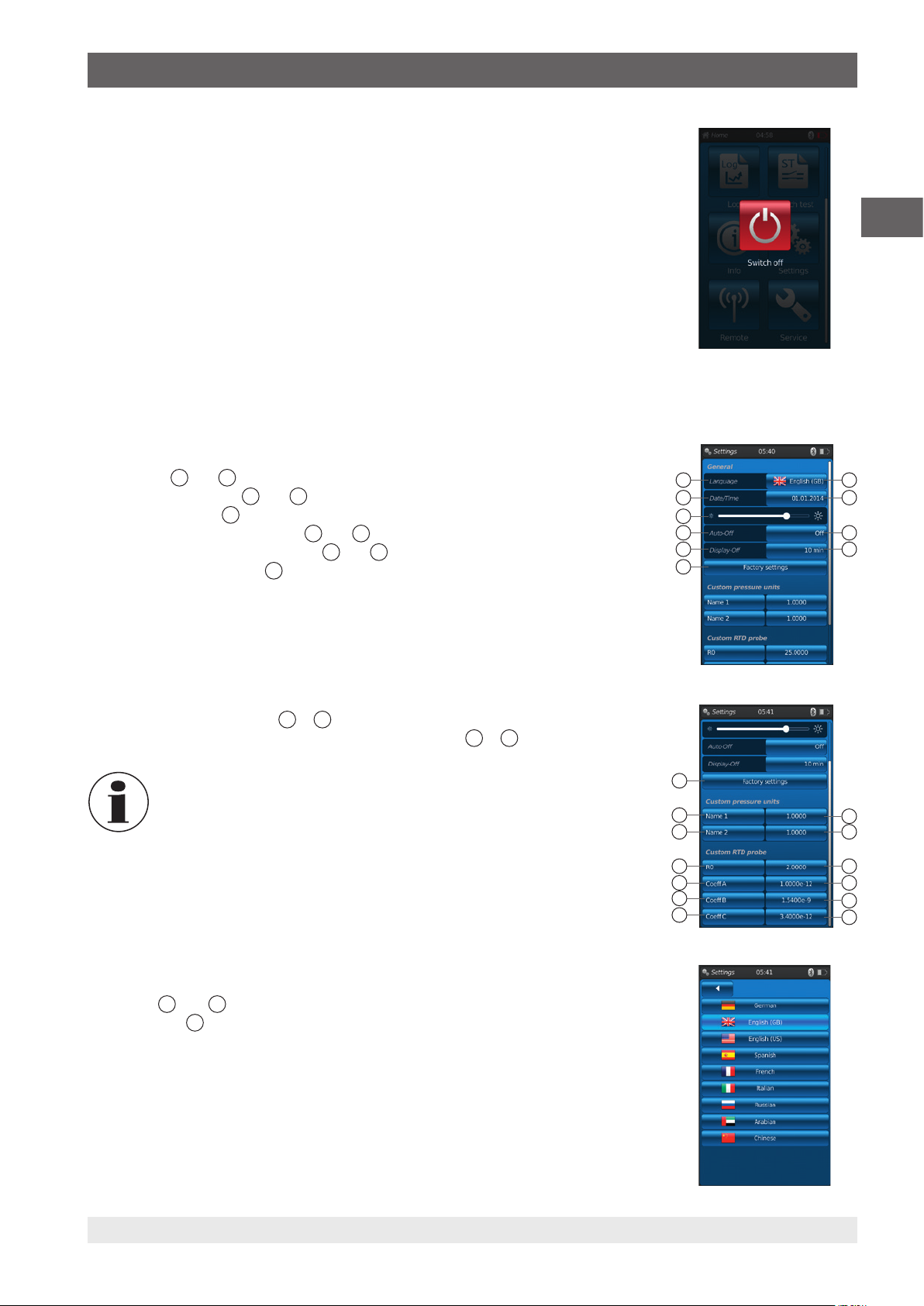
6.2.2 Application [Settings]
Press the [Settings] app to go to the instrument settings level.
The following information can be entered or changed:
■
Language 1 and
■
Current time and date 3 and
■
Display brightness
■
Setting of the “Auto-Off function” 6 and
■
Setting of the “Display-Off function” 8 and
■
Reset to “factory settings”
2
4
5
7
9
10
EN
21
43
5
76
98
10
■
User-defined pressure units 11 ...
■
User-defined temperature probes, including all coefficients 15 ...
14
The limits of the temperature coefficients are 0.0000 ... 999.0000.
Very small coefficient values can be entered via the exponential function. Here,
the [ . ](point) button must be pressed twice (e.g.: 1e-5 for 0.00001, 1e-6 for
0.000001 etc.).
Setting and/or changing:
Language
1. Press button
1
and 2:
2
.
2. Click on the country flag to select the language.
The desired operating language is set.
⇒
Return to the menu screen.
⇒
Press [◀] to cancel and return to the “Settings” menu screen.
22
10
11
13
15
17
19
21
12
14
16
18
20
22
14204467.02 03/2019 EN/DE
WIKA operating instructions portable process calibrator, model CPH7000 27
Page 28
6. Commissioning, operation
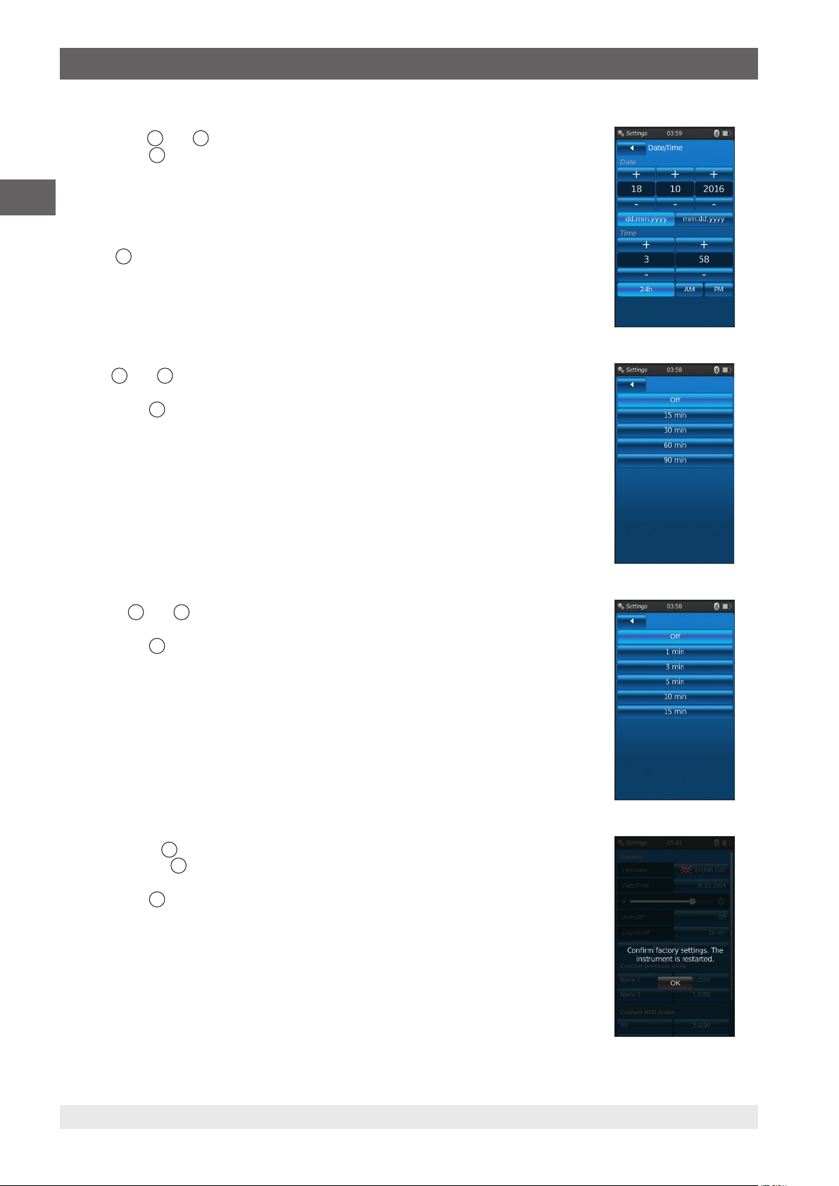
Date and time 3 and 4:
1. Press button
The date and time can be entered using the [+] and [-] buttons.
⇒
The [dd.mm.yyyy] and [mm.dd.yyyy] buttons are used to select the date format.
EN
⇒
The time display can be selected using the [24h], [AM] and [PM] buttons.
⇒
2. Press [◀] to return to the “Settings” menu screen and to save the settings.
Contrast 5:
The contrast or the brightness is adjusted via a scroll bar.
4
.
Auto off
Automatic switching off the process calibrator after a prescribed time
1. Press button
2. Select setting.
Display off
Automatic switching off the display after a prescribed time
1. Press button
2. Select setting.
6
and 7:
7
.
The following can be selected: Off, 15 min, 30 min, 60 min and 90 min
⇒
The desired time is set.
⇒
Return to the menu screen.
⇒
8
and 9:
9
.
The following can be selected: Off, 1 min, 3 min, 5 min, 10 min and 15 min
⇒
The desired time is set.
⇒
Return to the menu screen.
⇒
10
Factory settings
Pressing the button
1. Press button
Press [OK] to restore the settings and restart the instrument.
To cancel, press [Home].
Return to the main screen.
⇒
28 WIKA operating instructions portable process calibrator, model CPH7000
:
10
restores the process calibrator to factory settings.
10
.
14204467.02 03/2019 EN/DE
Page 29
6. Commissioning, operation
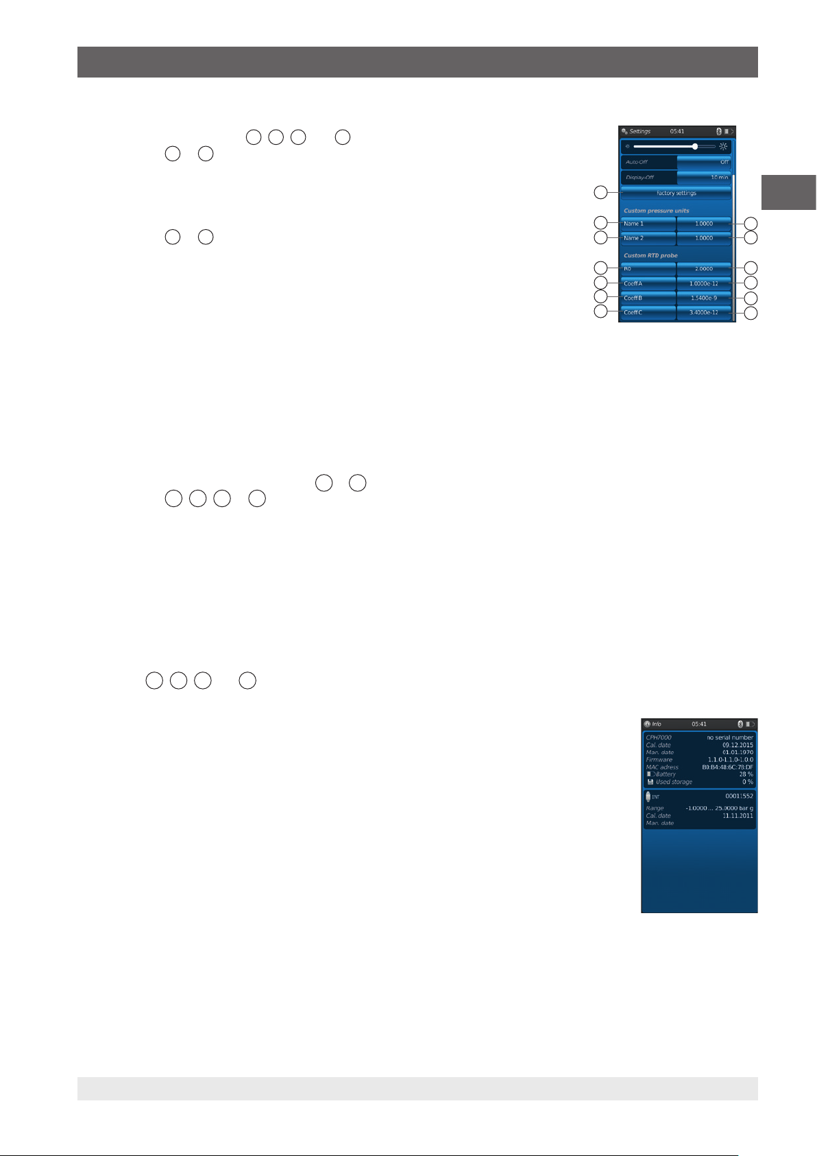
User-defined pressure units 11, 12, 13 and 14:
1. Press button
An alphanumerical keyboard will be displayed.
⇒
2. Enter the name of the user-defined pressure unit.
3. Confirm with [OK].
Return to the menu screen.
⇒
4. Press button
A numeric keypad will be displayed.
⇒
5. Enter the multiplication factor of the user-defined pressure unit.
The basic unit is “bar”.
⇒
6. Confirm with [OK].
Return to the menu screen.
⇒
Press [Delete] to delete the entire entry.
Press [] to delete the last entry step.
To cancel, press [Home].
Return to the menu screen.
⇒
The values will not be saved.
⇒
A maximum of two user-defined pressure units can be defined.
11
12
or 13.
or 14.
10
11
13
15
17
19
21
EN
12
14
16
18
20
22
15
User-defined temperature probes (RTD)
1. Press button
A numeric keypad will be displayed.
⇒
16, 18, 20
or 22.
... 22:
2. Enter numerical values.
3. Confirm with [OK].
Return to the menu screen.
⇒
Press [Delete] to delete the entire entry.
Press [] to delete the last entry step.
To cancel, press [Home].
Return to the menu screen.
⇒
The buttons
15, 17, 19
and 21 cannot be changed.
6.2.3 Application [Info]
Pressing the [Info] app displays all information about the CPH7000, including all internal and external
sensors connected.
The following information is displayed:
■
For the process calibrator:
Serial number, calibration date, date of manufacture, firmware, MAC address, battery status,
memory used
■
For a connected internal (int) or external sensor (EXT1, EXT2), a temperature probe Pt100 (RTD) or
the atmospheric module (AMB):
Measuring range, calibration date, date of manufacture
14204467.02 03/2019 EN/DE
WIKA operating instructions portable process calibrator, model CPH7000 29
Page 30

6. Commissioning, operation
6.2.4 Application [Remote]
Press the [Remote] app to go to the data transfer level.
This is where the WIKA-Wireless interface is switched on or off and the CPH7000 can be connected to a computer via this
interface.
EN
Switching on or off the WIKA-Wireless interface:
1. Press app [Remote].
2. Press button [Off] or [On]
During activation, the wireless sign will be displayed next to the battery icon.
⇒
During deactivation, it will not be displayed.
⇒
6.2.5 Application [Service]
All service-relevant information is listed in the [Service] application. A green check mark indicates that
the instrument is functioning correctly. A red X or the maximum sensor value shows an error.
The warning “Spanner” in the status bar is only acknowledged when, after an error, the service window
is opened.
▶
Press button [Home].
Return to the main screen.
⇒
Error message is no longer displayed.
⇒
30 WIKA operating instructions portable process calibrator, model CPH7000
14204467.02 03/2019 EN/DE
Page 31

6. Commissioning, operation
6.2.6 Further settings
6.2.6.1 Memory
If more than 90 % of the internal memory (1 GB RAM and 4 GB Flash) has been written, this message
appears.
To avoid data loss, transfer the data to an external storage medium and delete the data on the
CPH7000.
The connection to data transfer is WIKA-Wireless.
WIKA-Cal is the software for further analysis.
6.2.6.2 Rechargeable battery
If the battery capacity is below 10 %, this warning message appears.
The CPH7000 is to be charged immediately using the power supply unit provided, otherwise data loss
may occur.
EN
6.2.6.3 Changing the application task
If a data recording (e.g.: a logger process) is running in the background and a new measuring
application (e.g: measure) is started at the same time, a warning message appears (e.g.: logger is
active. Would you like to start the measurement anyway?).
■
Confirm with [OK].
The new measuring application is started
⇒
The old application is terminated; this logger process can be saved the next time you
open the app. It is not possible to continue the finished measurement.
■
To cancel, press [Home].
Return to the main screen.
⇒
Data continue to be recorded in the background.
⇒
14204467.02 03/2019 EN/DE
WIKA operating instructions portable process calibrator, model CPH7000 31
Page 32

6. Commissioning, operation
6.3 Measure
When using the electrical module, better results are achieved if the battery is not charged during the
measurement.
EN
6.3.1 Configuration of the “Measure” function
Press the [Measure] app to go to the “Measure” function.
In this function all measuring channels are displayed simultaneously.
One measuring channel consists of several segments.
The following parameters can be set:
■
Type of test item
■
INT, EXT1 1), EXT2 1), mAIN, mAIN24V, VIN, VIN24V, mA
1)
AMB
, RTD
■
Pin assignment
■
Shows that the CPH7000 is in the setting mode
■
Type of pressure (rel. or abs.)
■
If a barometric reference is installed in the CPH7000, it is possible to switch between rel.
and abs. The CPH7000 calculates the respective pressure value from the values of the barometer.
5
■
Unit
■
Zero point setting
1
1)
switch test, switch test
2
4
6
24V
, [---]
3
Out
, mA
24V, GAU 1), DIFF,
Out
Channel 1
Channel 2
Channel 3
6.3.1.1 Setting test item 1
1 2 3
By directly pressing one of the measuring channels, you go to the setting screen of the
measurands.
Out
1
.
, mA
24V, GAU 1), DIFF, AMB 1), RTD
Out
1)
switch test, switch test
24V
, [---]
1. Press button
The selection window of the possible methods of measurements is displayed.
⇒
You can choose between: INT, EXT1 1), EXT2 1), mAIN, mAIN24V, VIN, VIN24V,
⇒
mA
2. Select type of test item.
Return to the menu screen.
⇒
Selecting the type of pressure
4
3. Press button 4.
4. Select type of pressure (rel. or abs.)
If a barometric reference is installed in the CPH7000, it is possible to switch between rel. and abs. The CPH7000
⇒
calculates the respective pressure value from the values of the barometer.
Selecting the pressure unit
5
5. Press button 5.
The selection window of the possible pressure units is displayed.
⇒
6. Select pressure unit.
Return to the menu screen.
⇒
Zero point setting
6
7. Press button 6.
A numeric keypad will be displayed.
⇒
8. Adjust the zero point
9. Confirm with [OK].
Return to the menu screen.
⇒
456
32 WIKA operating instructions portable process calibrator, model CPH7000
14204467.02 03/2019 EN/DE
Page 33

6. Commissioning, operation
Pin assignment
1. Press button 2.
The selection window of the possible pin assignments is displayed.
⇒
You can choose between: INT, EXT1 1), EXT2 1), mAIN, mAIN24V, VIN, VIN24V, mA
⇒
GAU
2. Select pin assignment.
Return to the menu screen.
⇒
1) Displayed only if an external sensor is connected.
6.3.1.2 Setting test item 2 and 3
Test items 2 and 3 are programmed in the same way as test item 1.
If only 1 test item is measured, the type of test item [---] is selected in the selection window of test items 2 and 3.
6.3.2 Functions with symbol and meaning
Function Symbol Meaning
INT
EXT1
EXT2
RTD
INmA
INmA24V
INV Measuring voltage
INV24V
OUTmA
2
1)
, DIFF, AMB 1), RTD
, mA
1)
switch test, switch test
Internal reference pressure sensor
The current pressure value of the internal reference pressure sensor is displayed.
External reference pressure sensor to channel 1
The current pressure value of the external reference pressure sensor on channel 1 is
displayed.
This function can only be selected if also an external sensor is connected to channel 1.
External reference pressure sensor to channel 2
The current pressure value of the external reference pressure sensor on channel 2 is
displayed.
This function can only be selected if also an external sensor is connected to channel 2.
External temperature probe
The current temperature value of the external temperature probe is displayed.
This function can only be selected if also an external temperature probe is connected.
Measuring current
Activates the integrated electrical module for current measurement (0 ... 30 mA).
▶
Observe the electrical pin assignment, see chapter 6.3.5 “Measuring current”.
Measuring current with DC 24 V voltage supply
Activates the integrated electrical module for current measurement with simultaneous
DC 24 V (0 ... 30 mA) voltage supply by means of the CPH7000.
▶
Observe the electrical pin assignment, see chapter 6.3.6 “Measuring current with
simultaneous DC 24 V voltage supply”.
Activates the integrated electrical module for voltage measurement (DC 0 ... 30 V).
▶
Observe the electrical pin assignment, see chapter 6.3.7 “Measuring voltage”.
Measuring voltage with DC 24 V voltage supply
The measurement of the voltage value is accurate to 3 decimal places.
Activates the integrated electrical module for voltage measurement with simultaneous
DC 24 V (DC 0 ... 30 V) voltage supply by means of the CPH7000.
▶
Observe the electrical pin assignment, see chapter 6.3.8 “Measuring voltage with
simultaneous DC 24 V voltage supply”.
Simulating current
Current (mA) is generated from the integrated current source.
▶
Observe the electrical pin assignment, see chapter 6.3.9 “Simulating current”.
24V
, [---]
Out
Out
24V,
EN
14204467.02 03/2019 EN/DE
WIKA operating instructions portable process calibrator, model CPH7000 33
Page 34

EN
6. Commissioning, operation
Function Symbol Meaning
OUTmA24V
GAU
DIFF
Switch test
Switch test
24V
AMB
Simulating current with DC 24 V voltage supply
Current (mA) is generated from the integrated current source. The internal voltage supply is
constant (DC 24 V).
▶
Observe the electrical pin assignment, see chapter 6.3.10 “Simulating current with
simultaneous DC 24 V voltage supply”.
Manual pressure value acquisition
Allows a value to be manually entered (e.g.: of a pressure gauge).
▶
Observe the electrical pin assignment, see chapter 6.3.11 “Manual pressure value
acquisition”.
Displaying the difference value
Displays the difference value of two selected connections. For the subtraction (upper - lower
display) the significant figure rule applies.
Switch test
If no reference has been selected, the switch test cannot be selected as well.
The internal or an external sensor can be used as reference.
▶
Observe the electrical pin assignment, see chapter 6.6 “Switch test”.
Switch test with DC 24 V voltage supply
The switch is supplied by the CPH7000 with DC 24 V.
The internal or an external sensor can be used as reference.
▶
Observe the electrical pin assignment, see chapter 6.6 “Switch test”.
Displaying environmental parameters
Displays the values of the existing atmospheric module and of the integrated barometer. If
the atmospheric module is not connected, only dashes (-.---) are displayed for the measured
values temperature and humidity.
The “AMB” function can only be selected if the external atmospheric module or the barometer
is also connected. If the barometer is connected, the atmospheric pressure data can be
readout by the “AMB” function.
6.3.3 Measuring the external reference pressure sensor on channel 1 or on channel 2
“EXT1” and “EXT2” functions, buttons
Pin assignment channel 1
and
Process connection
may vary
14204467.02 03/2019 EN/DE
34 WIKA operating instructions portable process calibrator, model CPH7000
Page 35

6. Commissioning, operation
Pin assignment channel 2
The connection can also be made with the CPH7000 switched on.
Both ports can be used simultaneously.
6.3.4 Measuring the external temperature probe
EN
Process connection
may vary
“RTD” function,
Pin assignment
The connection point for the Pt100 probe is located on the CPH7000 on the right side of the case.
To carry out a temperature measurement, the [Measure] application has to be opened and the “RTD” function selected (in
one of the 3 channels).
The “RTD” function can only be selected when the temperature probe is connected.
button
14204467.02 03/2019 EN/DE
WIKA operating instructions portable process calibrator, model CPH7000 35
Page 36

6. Commissioning, operation
6.3.5 Measuring current
“INmA” function,
Pin assignment
EN
button
+
0 ... 30 mA
Current source
-
V
outVin
mA GND
To measure current, the [Measure] application has to be opened and the “INmA” function selected (in one of the 3 windows).
First, enter all settings in the CPH7000, then make the electrical connection.
6.3.6 Measuring current with simultaneous DC 24 V voltage supply
“INmA24V” function, button
Pin assignment
Pressure
Test
item
Reference
+ -
External/internal
pressure supply
V
outVin
mA GND
To measure current, the [Measure] application has to be opened and the “INmA24V” function selected (in one of the 3
windows).
36 WIKA operating instructions portable process calibrator, model CPH7000
14204467.02 03/2019 EN/DE
Page 37

6. Commissioning, operation
6.3.7 Measuring voltage
Function “INV”, button
Pin assignment
+
-
V
outVin
mA GND
Voltage source
To measure voltage, the [Measure] application has to be opened and the “INV” function selected (in one of the 3 windows).
6.3.8 Measuring voltage with simultaneous DC 24 V voltage supply
Function “INV24V”, button
Pin assignment
Pressure
EN
Test
item
+ -
V
outVin
mA GND
Reference
CPT7000
External/internal
pressure supply
V
= DC 24 V supply
out
Vin = measure DC 0 ... 30 V voltage signal
To measure voltage, the [Measure] application has to be opened and the “INV24V” function selected (in one of the 3
windows).
14204467.02 03/2019 EN/DE
WIKA operating instructions portable process calibrator, model CPH7000 37
Page 38

6. Commissioning, operation
6.3.9 Simulating current
Function “OUTmA”, button
Pin assignment
EN
-
Test item
0 ... 30 mA
+
+
-
V
outVin
mA GND
To simulate current, the [Measure] application has to be opened and the “OUTmA” function selected (in one of the 3
windows).
6.3.10 Simulating current with simultaneous DC 24 V voltage supply
Function “OUTmA24V”, button
Pin assignment
+ -
Test
item
V
outVin
mA GND
To simulate current with voltage supplied by the CPH7000, the [Measure] application has to be opened and the
“OUTmA24V” function selected (in one of the 3 windows).
38 WIKA operating instructions portable process calibrator, model CPH7000
14204467.02 03/2019 EN/DE
Page 39

6. Commissioning, operation
6.3.11 Manual pressure value acquisition
“GAU” function,
Pin assignment
To manually enter pressure values, the [Measure] application has to be opened and the “GAU” function selected (in one of
the 3 windows).
6.4 Calibrate
Press the [Calibrate] app to go to the calibration function.
1. Press app [Calibrate].
The [Calibrate] application window is displayed.
⇒
2. Press button [
The new calibration process can be started.
⇒
+ ]
button
EN
6.4.1 Preparing the calibration
The test items are defined first, the reference last.
6.4.1.1 Selecting the test item
Out
1
.
, mA
24V, GAU 1), DIFF, AMB 1), RTD
Out
1)
switch test, switch test
24V
, [---]
1. Press button
The selection window of the possible types of test item is displayed.
⇒
You can choose between: INT, EXT1 1), EXT2 1), mAIN, mAIN24V, VIN, VIN24V,
⇒
mA
Display 2 shows the pin assignment.
⇒
Display 3 shows that the CPH7000 is in the setting mode.
⇒
2. Select test item.
Return to the menu screen.
⇒
1) Displayed only if an external sensor is connected.
14204467.02 03/2019 EN/DE
WIKA operating instructions portable process calibrator, model CPH7000 39
1 2 3
456
Page 40

6. Commissioning, operation
Selecting the type of pressure
3. Press button 4.
4. Select type of pressure (rel. or abs.)
If a barometric reference is installed in the CPH7000, it is possible to switch
EN
⇒
between rel. and abs. The CPH7000 calculates the respective pressure value from
the values of the barometer.
Selecting the pressure unit
5. Press button 5.
The selection window of the possible pressure units is displayed.
⇒
6. Select pressure unit.
Return to the menu screen.
⇒
Zero point setting
7. Press button 6.
A numeric keypad will be displayed.
⇒
8. Adjust the zero point
9. Confirm with [OK].
Return to the menu screen.
⇒
Serial number
10. Press buttons 8 and 10.
A numeric keypad will be displayed.
⇒
11. Enter serial number and Tag number.
12. Confirm with [OK].
Return to the menu screen.
⇒
6
7
and Tag number
4
5
9
1 2 3
456
Measuring range
13. Press buttons 11 and 12.
A numeric keypad will be displayed.
⇒
Measuring range can be set from ... to .... .
⇒
14. Enter measuring ranges.
15. Confirm with [OK].
Return to the menu screen.
⇒
Pressure unit
16. Press button 14.
The selection window of the possible pressure units is displayed.
⇒
17. Select pressure unit.
Return to the “Reference” menu screen.
⇒
18. Press further button
19. Select type of pressure (rel. or abs.)
Accuracy 15 and
20. Press the button.
A numeric keypad will be displayed.
⇒
21. Enter accuracy.
22. Confirm with [OK].
Return to the menu screen.
⇒
The reference is selected by pressing [Continue ▶].
11
13
and type of pressure
16
and
14
12
14
.
1
7
9
11
13
15
3
8
10
12
14
16
40 WIKA operating instructions portable process calibrator, model CPH7000
14204467.02 03/2019 EN/DE
Page 41

6. Commissioning, operation
6.4.1.2 Selecting the reference
1. Press button
The selection window of the possible references is displayed.
⇒
The following can be selected: INT, EXT1 or EXT2
⇒
Display 2 shows the pin assignment.
⇒
Display 3 shows that the CPH7000 is in the setting mode.
⇒
2. Select reference.
Return to the menu screen.
⇒
Selecting the type of pressure
3. Press button 4.
4. Select type of pressure (rel. or abs.)
If a barometric reference is installed in the CPH7000, it is possible to switch between rel. and abs. The CPH7000
⇒
calculates the respective pressure value from the values of the barometer.
Selecting the pressure unit
5. Press button 5.
The selection window of the possible pressure units is displayed.
⇒
6. Select pressure unit.
Return to the menu screen.
⇒
Zero point setting
7. Press button 6.
A numeric keypad will be displayed.
⇒
8. Adjust the zero point
9. Confirm with [OK].
Return to the menu screen.
⇒
.
1
4
5
6
1
2 3
EN
456
20
17
and
18
21
22
and
19
Serial number
is automatically detected and transmitted
⇒
Measuring range
Measuring range from ... to is automatically detected and transmitted
⇒
Accuracy
is automatically detected and transmitted
⇒
Calibration date
is automatically detected and transmitted
⇒
[Next ▶] allows the calibration points to be defined.
1
17
18
20
22
19
21
14204467.02 03/2019 EN/DE
WIKA operating instructions portable process calibrator, model CPH7000 41
Page 42

6. Commissioning, operation
6.4.1.3 Determining calibration points
1. Press button [Continue ▶].
The programming window for the calibration points is displayed.
⇒
The measurement series and the test points for the calibration are defined in this window.
EN
Enter the number of measurement series
2. Press button 2.
A numeric keypad will be displayed.
⇒
3. Enter the number of measurement series.
Return to the menu screen.
⇒
Enter number of test points
4. Press button 4.
A numeric keypad will be displayed.
⇒
5. Enter the number of test points.
Return to the menu screen.
⇒
The measurement series is performed upwards
3
and
1
4
2
and
5
and downwards 7.
1
3
5
7
2
4
6
8
Determining test points
6
In the first cycle, the test points can be manually changed upwards 6.
During the first downward calibration
8
and in the subsequent measurement series, they automatically adapt this selection.
Press [Start ▶] to start the calibration process.
6.4.2 Carrying out the calibration
1. Once the default settings have been carried out, press [Start ▶] to start the calibration process.
The first calibration point is approached.
⇒
▶
Use the [] to record this pressure value and press the [] button to approach the next
calibration point.
▶
The [] button (in the top left corner) is used to discard the recorded calibration point and
move to the next calibration point by pressing the [
] button.
2. Repeat the procedure until all calibration points are reached.
Following values are shown:
■
Display measured value reference
■
Display measured value test item
■
Display of the current and next test points
■
Display measuring result of the current test point 5 in numerical form
2
3
4
The current calibration can be shown as graph or table.
1
2
3
4
5
8 7 6
Representation as graph
▶
Press button
6
6
Following values are shown:
■
Display measured value reference
■
Display measured value test item
■
Display of the current and next test points
■
Display measuring result of the current test point 5 as graph
2
3
4
8 7 6
42 WIKA operating instructions portable process calibrator, model CPH7000
1
2
3
5
14204467.02 03/2019 EN/DE
Page 43

6. Commissioning, operation
Representation as table
▶
Press button
7
7
Following values are shown:
■
Display measured value reference
■
Display measured value test item
■
Display of the current and next test points
■
Display measurement result of the current test point 5 as table
▶
Press button
The representation switches back to the numerical form.
⇒
8
2
3
4
6.4.3 Completing the calibration
1. When the last calibration point is reached, confirm by pressing the
[Apply
2. Confirm with the [Done
] button.
An overview of the calibration carried out is displayed.
⇒
] switching function.
The calibration process is saved under the [Calibrate] app.
⇒
If the calibration has been successfully carried out, it is marked with a
green frame, if not, with a red one.
1
2
3
EN
5
8 7 6
Unsuccessful calibration processes can be carried out again, see
chapter 6.4.5 “Repeating a calibration”.
6.4.4 Representation of the calibration results
Stored calibration processes are saved in table form in the main window under the
[Calibrate] app.
The description of the calibration is as follows:
■
Tag number
■
Test item with serial number and pressure range
2
3
Press the 1 button to delete a selected calibration process, see chapter 6.4.6 “Deleting a
calibration”.
Press the
4
button to prepare a new calibration process, see chapter 6.4.1 “Preparing the
calibration”.
6.4.5 Repeating a calibration
1. To carry out again an already stored calibration process, select it.
2. Press the [ReCal] button to create a copy of the calibration process selected.
The selected calibration process will not be overwritten.
⇒
All parameters are briefly displayed in advance and can be corrected, if necessary.
⇒
The new calibration process is created with the same parameters.
⇒
3. Press [Start] to start the copied calibration process.
4. For further procedures, see chapter 6.4.2 “Carrying out the calibration”.
4
3
1
2
14204467.02 03/2019 EN/DE
WIKA operating instructions portable process calibrator, model CPH7000 43
Page 44

6. Commissioning, operation
6.4.6 Deleting a calibration
Press the [Calibrate] app to open the calibration function.
All stored calibration processes are displayed.
Calibration processes can be deleted by pressing the [Delete] button.
EN
1. Press button [Delete].
2. Select the desired calibration process.
Several calibration processes can also be selected simultaneously.
⇒
3. Confirm with button [
The calibration process is deleted.
⇒
6.5 Logger
Press the [Logger] app to go to the logger function.
This function allows up to three different test items to be measured and displayed simultaneously.
1. Press app [Logger].
The [Logger] application window is displayed.
⇒
2. Press button [
The new logger process can be started.
⇒
+ ]
].
6.5.1 Preparing a logger process
To avoid inconsistencies during data acquisition, it is necessary to observe the sequence of test items 1, 2 and 3.
In order to carry out the logger process, test item 1 must always be entered in the first field. The other test items
must then be entered in the second and in the last field.
6.5.1.1 Setting test item 1
Out
1
.
, mA
24V, GAU 1), DIFF, AMB 1), RTD
Out
4
1)
switch test, switch test
24V
, [---]
1. Press button
The selection window of the possible types of test item is displayed.
⇒
You can choose between: INT, EXT1 1), EXT2 1), mAIN, mAIN24V, VIN, VIN24V,
⇒
mA
Display 2 shows the pin assignment.
⇒
Display 3 shows that the CPH7000 is in the setting mode.
⇒
2. Select type of test item.
Return to the menu screen.
⇒
1) Displayed only if an external sensor is connected.
Selecting the type of pressure
3. Press button 4.
4. Select type of pressure (rel. or abs.).
If a barometric reference is installed in the CPH7000, it is possible to switch between rel. and abs. The CPH7000
⇒
calculates the respective pressure value from the values of the barometer.
1
2 3
456
44 WIKA operating instructions portable process calibrator, model CPH7000
14204467.02 03/2019 EN/DE
Page 45

6. Commissioning, operation
Selecting the pressure unit
5. Press button 5.
The selection window of the possible pressure units is displayed.
⇒
6. Select pressure unit.
Return to the menu screen.
⇒
Zero point setting
7. Press button 6.
A numeric keypad will be displayed.
⇒
8. Adjust the zero point
9. Confirm with [OK].
Return to the menu screen.
⇒
6.5.1.2 Setting test item 2
The test item 2 is programmed in the same way as test item 1.
If only 1 test item is measured, the type of test item [---] is selected in the selection window of test items 2 and 3.
[Next ▶] allows further logger parameters to be defined.
6.5.1.3 Setting test item 3
1. Press button [Start ▶].
The programming window for test item 3 is displayed.
⇒
2. Press button
The selection window of the possible types of test item is displayed.
⇒
Selection = “DIFF” always calculates test item 2 - test item 1
⇒
3. Select types of test item.
Return to the menu screen.
⇒
6
1
.
5
EN
6.5.1.4 Setting logger parameters
Under the setting of “Test item 3”, the logger parameters are also set.
By selecting “Automatic” the following parameters are entered:
■
Automatic logger function
■
Manual logger function
Data points are recorded by manual confirmation.
⇒
■
Interval adjustable 9 and 10: 0.5 ... 3,600 s
■
Duration adjustable 11 and 12: 1 s ... 60 h
■
Start time 13 and 14: current or freely selectable start date
Observe the system time!
⇒
Setting the interval
1. Press button 10.
A numeric keypad will be displayed.
⇒
2. Enter the number of intervals.
3. Confirmed with [OK].
Return to the menu screen.
⇒
Setting the duration
4. Press button 12.
A numeric keypad will be displayed.
⇒
5. Enter the duration.
6. Confirmed with [OK].
Return to the menu screen.
14204467.02 03/2019 EN/DE
⇒
9
7
8
11
7
9
11
13
8
10
12
14
WIKA operating instructions portable process calibrator, model CPH7000 45
Page 46

6. Commissioning, operation
Setting the start time
13
7. Press button 14.
A numeric keypad will be displayed.
⇒
8. Enter a desired time or the current time.
9. Confirmed with [OK].
EN
Return to the menu screen.
⇒
10. Press [Start ▶] to start the logger process.
6.5.2 Representation of logger results
Representation of the logger process as table
Representation of the logger process as graph
The table shows the remaining time
2 and 3
Moving the screen
Moving the screen
2
(if selected).
4
to the right or left will display the test items.
3
upwards or downwards will display all measurement steps.
1
, the individual measuring points 5 and test items 1,
1
5
2
3
The graph shows the remaining time
In the lower half of the screen, a live graph
1
, test items 1, 2 and 3 6 ... 8 (if selected).
9
is shown. The live graph moves along the time
axis so that the current pressure value is always displayed.
▶
Press the [Stop] button 10 to terminate the process.
All measured values are displayed again before saving.
▶
The text field 12 can be used to add a comment on the process.
▶
Press the [Done ] button 11 to save this process.
4
10
1
6
7
8
9
11
46 WIKA operating instructions portable process calibrator, model CPH7000
12
14204467.02 03/2019 EN/DE
Page 47

6. Commissioning, operation
6.5.3 Analysing or repeating a logger process
Stored logger processes are saved in table form in the main window under the [Logger] app.
All logger processes performed are listed.
The following information is represented:
■
Date and start time
■
Test item 1, 2 and 3 (if selected)
If test items 2 and 3 have not been selected, these fields remain empty.
⇒
In order to analyse or repeat a process more precisely, it can be opened again.
1. Select the desired process and press the button.
The selected process will be opened.
⇒
The logger result will be displayed as graph or table.
⇒
The text field 12 can be used to add a comment on the copied process.
⇒
Repeating logger
2. Press the [ReLog] button to create a copy of the selected logger process.
The selected process will not be overwritten.
⇒
All parameters are briefly displayed in advance and can be corrected, if necessary.
⇒
3. Press [Start] to start the copied logger process.
Press the [Stop] button to terminate the logger process.
EN
6.5.4 Deleting logger
Individual logger processes can be deleted through “Waste bin =
Delete”.
Press the [Logger] app to open the logger function.
All stored processes are displayed.
Processes can be deleted by pressing the [Delete] button.
1. Press button [Delete].
2. Select the desired process and press the button.
Several processes can also be selected simultaneously.
⇒
3. Confirm with button [
The logger process is deleted.
⇒
4. Press button [Home].
Return to the main screen.
⇒
].
14204467.02 03/2019 EN/DE
WIKA operating instructions portable process calibrator, model CPH7000 47
Page 48

6. Commissioning, operation
6.6 Switch test
Enables the test of pressure switches. If no pressure sensor has been selected as reference (INT or
EXT1 / EXT2), the switch test cannot be selected as well.
EN
For switch tests with DC 24 V voltage supply, the switch will be directly supplied by the
CPH7000.
6.6.1 Switch test with external voltage supply
Button
Pin assignment
+
-
V
outVin
mA GND
6.6.2 Switch test with DC 24 V voltage supply by means of CPH7000
Button
Pin assignment
+
s
+ -
-
V
V
outVin
outVin
mA GND
mA GND
48 WIKA operating instructions portable process calibrator, model CPH7000
14204467.02 03/2019 EN/DE
Page 49

6. Commissioning, operation
6.6.3 Preparing the switch test
Press the [Switch test] app to go to the switch test function.
1. Press app [Switch test].
The [Switch test] application window is displayed.
⇒
2. Press button [ + ]
The new switch test process can be started.
⇒
6.6.3.1 Selecting the test item
1. Press button
Selection between “switch test” and “switch test with 24 V”.
⇒
Display 2 shows the pin assignment.
⇒
2. Use the button
Measuring values (switch point and hysteresis) can be deleted using the button 4.
⇒
Serial number
3. Press the buttons 6 and 8.
A numeric keypad will be displayed.
⇒
4. Enter serial number and Tag number.
5. Confirm with [OK].
Return to the menu screen.
⇒
Pressure range
6. Press the buttons
A numeric keypad will be displayed.
⇒
7. Enter pressure ranges.
8. Confirm with [OK].
Return to the menu screen.
⇒
Pressure unit
9. Press button 12.
The selection window of the possible pressure units is displayed.
⇒
10. Select pressure unit.
Return to the “Reference” menu screen.
⇒
11. Press button
Select type of pressure (rel. or abs.)
⇒
Signal
12. Press the buttons
A numeric keypad will be displayed.
⇒
13. Enter signal.
14. Confirm with [OK].
Return to the menu screen.
⇒
Accuracy
15. Press button 16.
A numeric keypad will be displayed.
⇒
16. Enter accuracy.
17. Confirm with [OK].
Return to the menu screen.
⇒
1
.
3
[INT], [EXT1] or [EXT2] to select the channel.
5
and Tag number
9
and 10.
12
and type of pressure
12
.
13
and 14.
15
7
12
EN
1
3
5
7
9
11
13
15
2
4
6
8
10
12
14
16
14204467.02 03/2019 EN/DE
WIKA operating instructions portable process calibrator, model CPH7000 49
Page 50

6. Commissioning, operation
18. Press button [Continue ▶].
The programming window for the reference is displayed.
⇒
A reference must be selected. You can select the internal reference or external references.
If no external reference pressure sensor is connected, the internal sensor will always be displayed.
EN
6.6.3.2 Selecting the reference
1. Press button [Continue ▶].
The programming window for the reference is displayed.
⇒
2. Press button
The selection window of the possible references is displayed.
⇒
The following can be selected: INT, EXT1 1), EXT2
⇒
1) Displayed only if an external sensor is connected.
Display 17 shows the pin assignment.
⇒
Display 18 shows that the CPH7000 is in the setting mode.
⇒
3. Select reference.
Return to the menu screen.
⇒
Selecting the type of pressure
4. Press button 19.
5. Select type of pressure (rel. or abs.)
If a barometric reference is installed in the CPH7000, it is possible to switch between rel. and abs. The CPH7000
⇒
calculates the respective pressure value from the values of the barometer.
Selecting the pressure unit
6. Press button 20.
The selection window of the possible pressure units is displayed.
⇒
7. Select pressure unit.
Return to the menu screen.
⇒
Zero point setting
8. Press button 21.
A numeric keypad will be displayed.
⇒
9. Adjust the zero point
10. Confirm with [OK].
Return to the menu screen.
⇒
1
.
1)
19
20
21
1
17 18
192021
Serial number
is automatically detected and transmitted
⇒
Pressure range
is automatically detected and transmitted
⇒
Pressure range
is automatically detected and transmitted
⇒
Calibration date
is automatically detected and transmitted
⇒
Press [Start] to start the switch test
50 WIKA operating instructions portable process calibrator, model CPH7000
22
23
25
27
and
and
24
26
1
21
22
24
26
23
25
14204467.02 03/2019 EN/DE
Page 51

6. Commissioning, operation
6.6.4 Carrying out and completing the switch test
1. Once the default settings have been carried out, press [Start ▶] to start the switch test.
The following is displayed:
■
Measured value of the reference
■
Measured value of the test item with open switch
■
Measured value of the test item with closed switch
■
Switch hysteresis of the test item
▶
The [] button (in the upper left corner) is used to discard the recorded switch test and to carry out the test again.
▶
Use the [Next ▶] button to confirm the recorded switch test.
An overview of the entire switch test is displayed.
⇒
EN
The following values are shown:
Specifications of the test item
■
Type of switch test (with internal or external voltage supply)
■
Serial number and Tag number
■
Measuring values and switch hysteresis
■
Measuring range of the test item
Specifications of the reference
■
Serial number
■
Measuring range
■
Accuracy
Comment
Necessary comments and notes can be entered here.
▶
To enter them, tap on the respective field.
2. Confirm with [Done
6.6.5 Analysing or repeating a switch test
Stored switch tests are saved in table form in the main window under the [Switch test] app.
All switch tests performed are listed.
The following information is represented:
■
Type of switch test (with internal or external voltage supply)
■
Serial number and Tag number
■
Measuring range
4
].
The switch test process will be saved under the [Switch test] app.
⇒
2
3
1
2
3
4
In order to analyse or repeat a process more precisely, it can be opened again.
1. Select the desired process and press the button.
The selected process will be opened.
⇒
All important information is displayed.
⇒
Repeating a switch test
2. Press the [ReSt] button to create a copy of the selected switch test.
The selected switch test process will not be overwritten.
⇒
All parameters are briefly displayed in advance and can be corrected, if necessary.
⇒
The text field 4 can be used to add a comment on the copied switch test.
⇒
3. Press [Start] to start the copied switch test process.
14204467.02 03/2019 EN/DE
WIKA operating instructions portable process calibrator, model CPH7000 51
Page 52

6. Commissioning, operation / 7. Faults
6.6.6 Delete switch test
Individual switch test processes can be deleted through “Waste bin =
Delete”.
Press the [Switch test] app to open the switch test function.
All stored processes are displayed.
EN
Processes can be deleted by pressing the [Delete] button.
1. Press button [Delete].
2. Select the desired process and press the button.
Several processes can also be selected simultaneously.
⇒
3. Confirm with button [
The switch test process is deleted.
⇒
4. Press button [Home].
Return to the main screen.
⇒
].
7. Faults
Personnel: Skilled personnel
CAUTION!
Physical injuries and damage to property and the environment
If faults cannot be eliminated by means of the listed measures, the process calibrator must be taken out of
operation immediately.
▶
Ensure that pressure or signal is no longer present and protect against accidental commissioning.
▶
Contact the manufacturer.
▶
If a return is needed, please follow the instructions given in chapter 9.1 “Return”.
WARNING! (Only for model CPT7000)
Physical injuries and damage to property and the environment caused by hazardous media
Upon contact with hazardous media (e.g. oxygen, acetylene, flammable or toxic substances), harmful media (e.g.
corrosive, toxic, carcinogenic, radioactive), and also with refrigeration plants and compressors, there is a danger
of physical injuries and damage to property and the environment.
Should a failure occur, aggressive media with extreme temperature and under high pressure or vacuum may be
present at reference pressure sensor model CPT7000.
▶
For these media, in addition to all standard regulations, the appropriate existing codes or regulations must also
be followed.
For contact details see chapter 1 “General information” or the back page of the operating instructions.
Faults Causes Measures
The instrument cannot be switched on. Rechargeable battery discharged. Connect the power supply unit and charge the
battery.
Rechargeable battery defective. Contact the manufacturer.
Data transfer does not work. WIKA-Wireless was not activated. Activate WIKA-Wireless, see chapter
6.2.4 “Application [Remote]”.
52 WIKA operating instructions portable process calibrator, model CPH7000
14204467.02 03/2019 EN/DE
Page 53

8. Maintenance, cleaning and recalibration
8. Maintenance, cleaning and recalibration
Personnel: Skilled personnel
For contact details see chapter 1 “General information” or the back page of the operating instructions.
8.1 Maintenance
The model CPH7000 process calibrator and the model CPT7000 reference pressure sensors are is maintenance-free.
The same does not apply to the integrated pump. The pump must be serviced at regular intervals by the manufacturer.
Repairs must only be carried out by the manufacturer.
The pumping unit is a consumable. Regular maintenance is recommended after 100,000 pump cycles at the
latest. Under normal use conditions, this corresponds to a service life of 2 years.
8.2 Cleaning
CAUTION!
Physical injuries and damage to property and the environment
Improper cleaning may lead to physical injuries and damage to property and the environment. Residual media at
the dismounted instrument can result in a risk to persons, the environment and equipment.
▶
Carry out the cleaning process as described below.
1. Prior to cleaning, vent and switch off the instrument.
2. Clean the instrument with a moist cloth.
Electrical connections must not come into contact with moisture!
EN
CAUTION!
Damage to the instrument
Improper cleaning may lead to damage to the instrument!
▶
Do not use any aggressive cleaning agents.
▶
Do not use any pointed and hard objects for cleaning.
▶
Do not use solvents or abrasives for cleaning.
8.3 Recalibration
DKD/DAkkS certificate - official certificates:
We recommend that the instrument is regularly recalibrated by the manufacturer, with time intervals of approx. 12 months. The
basic settings will be corrected if necessary.
14204467.02 03/2019 EN/DE
WIKA operating instructions portable process calibrator, model CPH7000 53
Page 54

9. Return and disposal
9. Return and disposal
Personnel: Skilled personnel
9.1 Return
EN
Strictly observe the following when shipping the instrument:
All instruments delivered to WIKA must be free from any kind of hazardous substances (acids, bases, solutions, etc.) and must
therefore be cleaned before being returned.
WARNING!
Physical injuries and damage to property and the environment through residual media
Residual media at the instrument can result in a risk to persons, the environment and equipment.
▶
Clean the instrument, see chapter 8.2 “Cleaning”.
Only return the instrument in the supplied plastic case!
To avoid damage:
▶
Label the shipment as transport of a highly sensitive measuring instrument.
Information on returns can be found under the heading “Service” on our local website.
Rechargeable battery
The integrated lithium-ion battery is subject to the requirements of the Dangerous Goods Directive. Special
requirements for packaging and labelling must be observed when shipping. A dangerous goods expert must be
consulted when preparing the package.
Do not ship the instrument if the battery is damaged or defective.
Observe the different dangerous goods requirements relative to the respective modes of transport and any other
national regulations.
The rechargeable battery is permanently installed in the model CPH7000 process calibrator. In case the battery
stops working, contact the manufacturer.
The battery is a consumable, all rechargeable batteries have a limited number of charging cycles and may need
to be checked at any given time. If you remark that the CPH7000 must be charged more frequently, contact the
manufacturer immediately.
For contact details see chapter 1 “General information” or the back page of the operating instructions.
9.2 Disposal
Incorrect disposal can put the environment at risk.
Dispose of instrument components and packaging materials in an environmentally compatible way and in accordance with the
country-specific waste disposal regulations.
Do not dispose of with household waste. Ensure a proper disposal in accordance with national regulations.
54 WIKA operating instructions portable process calibrator, model CPH7000
14204467.02 03/2019 EN/DE
Page 55

10. Specifications
10. Specifications
10.1 Digital process calibrator
Digital process calibrator model CPH7000
Display
Display Touchscreen colour display
Display resolution up to 5 digits; selectable
Pressure units mbar, bar, psi, Pa, kPa, hPa, MPa, mmHg, cmHg, inHg, mmH
inH2O (20 °C), inH2O (60 °F), inHg (0 °C), inHg (60 °F), kg/cm², kp/cm², lbf/ft², kN/m², atm,
Torr, micron, g/l (20 °C), kg/m³ (20 °C) as well as two user-defined units
Settings
Applications (apps) Measure, Calibrate, Logger, Switch test
Measuring rate 50 values/s
Menu languages English, German, Spanish, French, Italian, Russian, Arabic, Chinese (settable)
Connections
External pressure sensors
1)
External atmospheric module
External temperature probe
Manual pressure generation
1)
1)
1)
max. 2, compatible with model CPT7000 reference pressure sensors
max. 1 atmospheric module
max. 1 external temperature probe
2)
2)
-0.85 … +25 bar (-12.3 ... +360 psi)
Voltage supply
Power supply Internal lithium-ion rechargeable battery (typical charging time < 5 h)
Battery life typically 8 hours
3)
Permissible ambient conditions
Operating temperature -10 ... +50 °C (-4 ... +122 °F)
Storage temperature -20 ... +60 °C (-4 ... +140 °F)
Air humidity at 35 °C (95 °F): max. 90 % r. h. (non-condensing)
at 40 °C (104 °F): max. 75 % r. h. (non-condensing)
at 50 °C (122 °F): max. 45 % r. h. (non-condensing)
Shock and vibration 15 g per EN 60068-2-6
Communication
Interface WIKA-Wireless
4)
Case
Material PC + ABS blend
Ingress protection IP54 category 2
Dimensions see technical drawing
Weight approx. 1.9 kg (4.16 lbs) without internal pump and reference sensor
approx. 2.5 kg (5.51 lbs) incl. internal pump and reference sensor
1) Available as an option
2) The temperature probe and the atmospheric module use the same connection.
It cannot be used simultaneously.
3) In continuous operation (without backlighting, WIKA-Wireless is not active and the electrical module does not supply voltage/current!).
4) Requires a PC with Bluetooth® 2.1 interface
O, mH2O, inH2O (4 °C),
2
EN
14204467.02 03/2019 EN/DE
WIKA operating instructions portable process calibrator, model CPH7000 55
Page 56

10. Specifications
Internal sensor technology
Pressure
Gauge pressure bar -1 ... +1 -1 ... 5 -1 ... 10 -1 ... 20 -1 ... 25
EN
Absolute pressure bar abs. 0 ... 1 0 ... 1.6 0 ... 6 0 ... 10 0 ... 20 0 ... 25
Overpressure safety 3 times
Accuracy of the measuring chain
Resolution 5 digits
Pressure connection G 1/8 B female thread (only if the pneumatic unit has been selected)
Electrical safety
Resistance to overvoltage Yes
Short-circuit resistant Ye s
Reverse polarity protection Ye s
Voltage-resistant Up to 60 V
Input impedance
Current measurement 20 Ω
Voltage measurement 1 MΩ
Current
Measuring input 0 … 30 mA
Measuring output 0 … 30 mA
Resolution 1 µA
Accuracy Measuring: 0.01 % ±1 µA
Voltage
Measuring input DC 0 … 30 V
Measuring output DC 24 V
Resolution 1 mV
Accuracy 0.01 % of reading ±1 mV
Barometric reference
Measuring range 850 ... 1,100 mbar (12.3 ... 16 psi)
Accuracy ±1 mbar
1) Available as an option
5) The internal reference sensor is only available in combination with the pneumatic unit.
6) It is defined by the total measurement uncertainty, which is expressed with the coverage factor (k = 2) and includes the following factors: the intrinsic performance of the instrument, the
7) Calibrated at 23 °C (74 °F) and in vertical mounting position
8) Im Falle einer Störbeeinflussung durch hochfrequente elektromagnetische Felder in einem Frequenzbereich von 200 ... 300 MHz ist für die Stromausgabefunktion mit einer erhöhten
9) The barometric reference can be used to switch pressure types absolute <=> gauge.
5)
psi -14.5 ... +14.5 -14.5 ... +70 -14.5 ... +145 -14.5 ... +300 -14.5 ... +360
psi abs. 0 ... 14.5 0 ... 23 0 ... 87 0 ... 145 0 ... 290 0 ... 360
6)
0.025 % of span
Supplying: 0.01 % ±2 µA
1) 9)
measurement uncertainty of the reference instrument, long-term stability, influence of ambient conditions, drift and temperature effects over the compensated range during a periodic
zero point adjustment.
Abweichung von bis zu 0,1 % zu rechnen.
With gauge pressure sensors, the measuring range of the sensor must begin with -1 bar (-15 psi) in order to carry out a complete absolute pressure emulation.
7)
8)
Power supply unit model FW7530
Input voltage AC 100 ... 240 V, 50 ... 60 Hz
Output voltage DC 12 V
Nominal Output current 2,500 mA
Permissible ambient conditions
Operating temperature 0 ... 40 °C (32 ... +104 °F); up to 90 % r. h. (non-condensing)
Storage temperature -40 ... +70 °C (-40 ... +158 °F)
Air humidity 20 ... 80 % r. h. (non-condensing)
56 WIKA operating instructions portable process calibrator, model CPH7000
14204467.02 03/2019 EN/DE
Page 57

10. Specifications
10.2 Temperature probe Pt100
Temperature probe Pt100
Measuring range -50 ... +250 °C (-58 ... +482 °F)
Accuracy 1/10 DIN, class B ±0,1 °C
Probe length 200 mm (7.87 in)
Probe diameter 3 mm (0.12 in)
Cable length 1 m (3.28 ft)
Connection to CPH7000 max. 1 external temperature probe
User-defined RTD probe Input of the coefficients of R0, A, B and C
1)
2)
10.3 Atmospheric module
Atmospheric module
Measuring range
Air humidity 0 ... 100 % r. h.
Temperature -30 ... +125 °C (-22 ... +257 °F)
Accuracy
Air humidity ±5 % r. h.
Temperature ±0.2 °C (0.36 °F)
Connection to CPH7000 max. 1 atmospheric module
1)
2)
EN
10.4 WIKA-Wireless
WIKA-Wireless
Frequency range 2,400 ... 2,500 MHz
HF output power max. 2 dBm (+ 2 dBi)
Number of channels 79
Channel spacing 1 MHz
Bandwidth 80 MHz
Output power 4 dBm / 10 mW
1) Available as an option
2) The temperature probe and the atmospheric module use the same connection.
It cannot be used simultaneously.
4) Requires a PC with Bluetooth® 2.1 interface
4)
The use of the radio module is subject to the provisions and regulations of the respective country and the module
may only be used in the countries for which a country certification is available:
Austria, Belgium, Cyprus, Czech Republic, Denmark, Estonia, Finland, France, Germany, Greece, Hungary,
Ireland, Italy, Latvia, Lithuania, Luxembourg, Malta, Poland, Portugal, Slovakia, Slovenia, Spain, Sweden,
Netherlands, United Kingdom, Switzerland, and Norway.
Units with FCC / IC marking are also approved for USA and Canada.
Check whether these approvals apply to your country. It is not permitted to use WIKA-Wireless in countries
without valid radio approval.
14204467.02 03/2019 EN/DE
WIKA operating instructions portable process calibrator, model CPH7000 57
Page 58

10. Specifications
Dieses Gerät erfüllt Teil 15 der FCC-Vorschriften.
Der Betrieb unterliegt den beiden folgenden Bedingungen:
1. Dieses Gerät darf keine schädlichen Störungen verursachen.
2. Dieses Gerät muss alle empfangenen Störungen annehmen, einschließlich Störungen, die zu unbeabsichtigtem Betrieb
EN
führen können.
FCC and IC Notice:
This instrument complies with part 15 of the FCC rules.
Operation is subject to the following two conditions:
1. This instrument may not cause harmful interference.
2. This instrument must accept any interference received, including interference that may cause undesired operation.
Cet instrument satisfait à la section 15 de la réglementation FCC
L'exploitation est autorisée aux deux conditions suivantes :
1. l'appareil ne doit pas produire de brouillage, et
2. l'utilisateur de l'appareil doit accepter tout brouillage radioélectrique subi, même si le brouillage est susceptible d'en
compromettre le fonctionnement.
This equipment has been tested and found to comply with the limits for a class B digital device, pursuant to part
15 of the FCC rules. These limits are designed to provide reasonable protection against harmful interference
in a residential installation. This equipment generates, uses and can radiate radio frequency energy and, if not
installed and used in accordance with the instructions, may cause harmful interference to radio communications.
However, there is no guarantee that interference will not occur in a particular installation.
10.5 Reference pressure sensor model CPT7000
Reference pressure sensor model CPT7000
Pressure range
Gauge pressure bar -0.25 ... +0.25 -0.4 ... +0.4 -0.6 ... +0.6 -1 ... 0 -1 ... +0.6
-1 ... +1 -1 ... +1.5 -1 ... +2.5 -1 ... +3 -1 ... +5
-1 ... +9 -1 ... +10 -1 ... +15 -1 ... +24 -1 ... +25
-1 ... +39 -1 ... +40
0 ... 0.25 0 ... 0.4 0 ... 0.6 0 ... 1 0 ... 1.6
0 ... 2.5 0 ... 4 0 ... 6 0 ... 10 0 ... 16
0 ... 25 0 ... 40 0 ... 60 0 ... 100 0 ... 160
0 ... 250 0 ... 400 0 ... 600 0 ... 700 0 ... 1,000
10)
10)
0 ... 2,500
0 ... 8,000
0 ... 1,600
0 ... 6,000
psi -4 ... +4 -6 ... +6 -8 ... +8 -14.5 ... 0 -14.5 ... +8
-14.5 ... +14.5 -14.5 ... +23 -14.5 ... +36 -14.5 ... +44 -14.5 ... +70
-14.5 ... +130 -14.5 ... +145 -14.5 ... +220 -14.5 ... +350 -14.5 ... +360
-14.5 ... +560 -14.5 ... +580
0 ... 4 0 ... 6 0 ... 8 0 ... 14.5 0 ... 23
0 ... 36 0 ... 60 0 ... 90 0 ... 145 0 ... 230
0 ... 360 0 ... 580 0 ... 870 0 ... 1,450 0 ... 2,320
0 ... 3,630 0 ... 5,800 0 ... 8,700 0 ... 10,150 0 ... 14,500
0 ... 25,000 0 ... 40,000 0 ... 50,000 0 ... 60,000 0 ... 75,0000
0 ... 85,000 0 ... 100,000 0 ... 150,000
10)
10)
0 ... 3,000
0 ... 10,000
10)
10)
0 ... 4,000
10)
0 ... 5,000
10)
10) > 1,000 ... < 4,000 bar: expanded accuracy of 0.15 % FS
≥ 4,000 bar: expanded accuracy of 0.25 % FS
58 WIKA operating instructions portable process calibrator, model CPH7000
14204467.02 03/2019 EN/DE
Page 59

10. Specifications
Reference pressure sensor model CPT7000
Absolute pressure bar abs. 0 ... 0.25 0 ... 0.4 0 ... 0.6 0 ... 1 0 ... 1.6
0 ... 2.5 0 ... 4 0 ... 6 0 ... 10 0 ... 16
0 ... 25 0 ... 40
psi abs. 0 ... 4 0 ... 6 0 ... 8 0 ... 14.5 0 ... 23
0 ... 36 0 ... 60 0 ... 90 0 ... 145 0 ... 230
0 ... 360 0 ... 580
Overpressure safety 3 times; < 25 bar
2 times; > 25 bar ... ≤ 600 bar
1.5 times; > 600 bar ... ≤ 1,600 bar
1.3 times; > 1,600 bar
1.1 times; > 6,000 bar
Process connection
■
Selectable versions
G ⅜ B
■
G ¼ B
■
G ¼ female
■
G ½ B
■
G ½ male on G ¼ female
■
¼ NPT
■
½ NPT
■
M16 x 1.5 female with sealing cone
■
M18 x 1.5 male on G ¼ female
■
9/16-18 UNF female F250-C
■
R ½ per ISO7 (DIN 2999)
Sensor data
Accuracy
6)
0.025 % of span
7)
Resolution 5 digits
Compensated range 10 ... 60 °C (50 ... 140 °F)
Material
Wetted parts Stainless steel (with measuring ranges ≤ 25 bar (≤ 360 psi) Elgiloy
Internal transmission fluid Synthetic oil (only for measuring ranges up to 25 bar (360 psi))
Reference conditions per IEC 61298-1
Atmospheric pressure 860 hPa < P < 1,060 hPa (12.5 psi < P < 15.4 psi)
Ambient temperature 18 °C < T < 28 °C, typ. 23 °C
Air humidity 35 % r. h. < T < 95 % r. h. , typ. 55 % r. h.
Position Hand-held lying face-up
Permissible ambient conditions
Medium temperature -20 ... +60 °C (-4 ... +140 °F)
11)
-20 ... +85 °C (-4 ... +185 °F)
Operating temperature -20 ... +60 °C (-4 ... +140 °F)
Storage temperature -20 ... +85 °C (-4 ... +185 °F)
Relative humidity 0 ... 95 % r. h. (non-condensing)
Temperature compensation 10 ... 60 °C (50 ... 140 °F)
Temperature coefficient Zero point = 0.1 % / 10 K
Span = 0.1 % / 10 K
3 times; < 360 psi
2 times; > 360 psi ... ≤ 8,700 psi
1.5 times; > 8,700 psi ... ≤ 25,000 psi
1.3 times; > 25,000 psi
1.1 times; > 85,000 bar
■
G ½ B flush with O-ring of NBR
■
G ½ B flush with O-ring of EPDM
■
G 1 B flush with O-ring of NBR
■
G 1 B flush with O-ring of EPDM
■
½ NPT male on ¼ NPT female
■
½ NPT female
■
M20 x 1.5
■
M20 x 1.5 female with sealing cone
®
in addition)
EN
6) It is defined by the total measurement uncertainty, which is expressed with the coverage factor (k = 2) and includes the following factors: the intrinsic performance of the instrument, the
measurement uncertainty of the reference instrument, long-term stability, influence of ambient conditions, drift and temperature effects over the compensated range during a periodic
zero point correction.
7) Calibrated at 23 °C (74 °F) and in vertical mounting position
10) > 1,000 ... < 4,000 bar: expanded accuracy of 0.15 % FS
≥ 4,000 bar: expanded accuracy of 0.25 % FS
11) For oxygen versions, the medium temperature must not exceed 60 °C (140 °F).
14204467.02 03/2019 EN/DE
WIKA operating instructions portable process calibrator, model CPH7000 59
Page 60

EN
10.6 Approvals
10. Specifications
Reference pressure sensor model CPT7000
Case
Material Stainless steel
Connection to the CPH7000 Option: External operation via 1 m or 3 m (3.28 ft or 9.84 ft) connection cable (plug-and-play)
Ingress protection IP65 / IP67 when connected
Dimensions see technical drawing
Weight approx. 230 g (0.5 lbs.)
Logo Description Country
EU declaration of conformity for CPH7000
■
EMC directive
EN 61326 emission (group 1, class B) and interference immunity (portable measuring
equipment)
■
R&TTE directive
EN 300 328 harmonised frequency range 2,400 … 2,500 MHz is used; Bluetooth® Classic,
max. transmission power 10 mW. The instrument may be used without limitations in the EU and
also CH, NO and LI.
■
Protection of health and safety
■
RoHS directive
EU declaration of conformity for CPT7000
■
EMC directive
EN 61326 emission (group 1, class B) and interference immunity (industrial application)
■
Pressure equipment directive
PS > 200 bar, module A, pressure accessory
■
RoHS directive
European Union
European Union
10.7 Certificates
Certificate
Calibration Standard: 3.1 calibration certificate per EN 10204
Option: DKD/DAkkS calibration certificate
Recommended recalibration interval 1 year (dependent on conditions of use)
10.8 Patents, property rights
Patente
Design registered under USD 786.719S
Approvals and certificates, see website
For further specifications see WIKA data sheet CT 15.51 and the order documentation.
60 WIKA operating instructions portable process calibrator, model CPH7000
14204467.02 03/2019 EN/DE
Page 61

10. Specifications
10.9 Dimensions in mm (in)
Digital process calibrator model CPH7000
Reference pressure sensor
model CPT7000
EN
14204467.02 03/2019 EN/DE
WIKA operating instructions portable process calibrator, model CPH7000 61
Page 62

EN
11. Accessories
11. Accessories
Order code
Special features CPH-A-70
Adapter set “Standard”
Consisting of:
■
G ½ male to G ½, G ¼, ½ NPT or ¼ NPT female
■
Sealing set
-G-
Adapter set for 4 mm hose connection
Consisting of:
■
G ⅛ female to G ½, G ¼, ½ NPT or ¼ NPT female
■
1 m hose
■
5 hose coupling
■
Sealing set
Adapter set with hose connection
Consisting of:
G ⅛ via hose to G ¼, G ½, ¼ NPT or ½ NPT female
Pressure connection set model Minimess 1620
incl. test item hose, length 1 m [3.28 ft]
Dirt trap set “Standard”
Consisting of:
■
Dirt trap
■
Sealing set
■
Hose
■
Hose connection G ⅛ via hose to G ¼, G ½, ¼ NPT or ½ NPT female
Dirt trap set with knurled nut
Consisting of:
■
Dirt trap
■
Knurled nut
■
Sealing set
■
Hose
■
Hose connection G ⅛ via hose to G ¼, G ½, ¼ NPT or ½ NPT female
Sealing set
Consisting of:
■
4 x G ½ USIT seals
■
2 x G ¼ USIT seals
■
Plastic box
Plastic case
For 1 x process calibrator model CPH7000 for storage and transport
-F-
-7-
-8-
-L-
-M-
-D-
-K-
Carrying system -U-
Belt and accessory bag -A-
Carrying system and accessory belt bag -W-
62 WIKA operating instructions portable process calibrator, model CPH7000
14204467.02 03/2019 EN/DE
Page 63

11. Accessories
Order code
Special features CPH-A-70
Test cable set
■
3 x black
■
3 x red
■
Various adapter
Sensor connection cable
for reference pressure sensor model CPT7000; length 1 m [3.28 ft] -Sfor reference pressure sensor model CPT7000; length 3 m [9,84] -V-
Temperature probe Pt100
(uncalibrated)
Atmospheric module -E-
Power supply unit -N-
-T-
-P-
EN
WIKA-Wireless-USB-Stick -B-
Ordering information for your request
WIKA accessories can be found online at www.wika.com.
1. Order code: CPH-A-70
2. Option:
⇓
[ ]
14204467.02 03/2019 EN/DE
WIKA operating instructions portable process calibrator, model CPH7000 63
Page 64

EN
64 WIKA operating instructions portable process calibrator, model CPH7000
14204467.02 03/2019 EN/DE
Page 65

Inhalt
Inhalt
1. Allgemeines 68
1.1 Software-Lizenzvertrag . . . . . . . . . . . . . . . . . . . . . . . 68
2. Kurzübersicht 69
2.1 Überblick . . . . . . . . . . . . . . . . . . . . . . . . . . . 69
2.2 Beschreibung . . . . . . . . . . . . . . . . . . . . . . . . . . 70
2.3 Lieferumfang . . . . . . . . . . . . . . . . . . . . . . . . . . 70
2.4 Produktpass . . . . . . . . . . . . . . . . . . . . . . . . . . 70
3. Sicherheit 70
3.1 Symbolerklärung . . . . . . . . . . . . . . . . . . . . . . . . . 70
3.2 Bestimmungsgemäße Verwendung. . . . . . . . . . . . . . . . . . . 71
3.3 Fehlgebrauch . . . . . . . . . . . . . . . . . . . . . . . . . . 71
3.4 Verantwortung des Betreibers . . . . . . . . . . . . . . . . . . . . 72
3.5 Personalqualifikation. . . . . . . . . . . . . . . . . . . . . . . . 72
3.6 Beschilderung, Sicherheitskennzeichnungen . . . . . . . . . . . . . . . 73
3.6.1 Typenschild für Prozesskalibrator Typ CPH7000 . . . . . . . . . . . . . . . . . . . . . 73
3.6.2 Typenschild für Referenz-Drucksensor Typ CPT7000 . . . . . . . . . . . . . . . . . . 73
4. Aufbau und Funktion 74
4.1 Aufbau . . . . . . . . . . . . . . . . . . . . . . . . . . . . 74
4.2 Funktionen und Datenübertragung mit der Kalibriersoftware WIKA-Cal . . . . . . 74
4.2.1 WIKA-Cal Konfiguration (auch mit der Demoversion möglich) . . . . . . . . . . . . . . 75
4.2.2 WIKA-Cal - Cal-Template . . . . . . . . . . . . . . . . . . . . . . . . . . . . . . . . . . 77
4.2.3 WIKA-Cal - Log-Template . . . . . . . . . . . . . . . . . . . . . . . . . . . . . . . . . . 78
4.2.4 WIKA-Cal - Schaltertest-Template . . . . . . . . . . . . . . . . . . . . . . . . . . . . . 79
4.3 Spannungsversorgung . . . . . . . . . . . . . . . . . . . . . . . 79
4.3.1 Akku. . . . . . . . . . . . . . . . . . . . . . . . . . . . . . . . . . . . . . . . . . . . . . 80
4.3.2 Einsatz des Netzteils . . . . . . . . . . . . . . . . . . . . . . . . . . . . . . . . . . . . 80
4.3.3 Während des Ladevorgangs . . . . . . . . . . . . . . . . . . . . . . . . . . . . . . . . 81
4.4 Elektrische Anschlüsse . . . . . . . . . . . . . . . . . . . . . . . 81
4.5 Mechanischer Anschluss . . . . . . . . . . . . . . . . . . . . . . 82
4.6 Pumpe . . . . . . . . . . . . . . . . . . . . . . . . . . . . 82
4.7 Barometer . . . . . . . . . . . . . . . . . . . . . . . . . . . 82
4.8 Referenz-Drucksensor Typ CPT7000 . . . . . . . . . . . . . . . . . . 82
4.8.1 Anschluss des Referenz-Drucksensors Typ CPT7000 . . . . . . . . . . . . . . . . . . 83
4.8.2 Elektrischer Anschluss des CPT7000 Referenz-Drucksensors am CPH7000 . . . . . 83
4.9 Tragesystem . . . . . . . . . . . . . . . . . . . . . . . . . . 83
4.10 Display . . . . . . . . . . . . . . . . . . . . . . . . . . . . 84
4.10.1 Applikationen (Apps) . . . . . . . . . . . . . . . . . . . . . . . . . . . . . . . . . . . . 84
4.10.2 Symbole des Statusbalkens . . . . . . . . . . . . . . . . . . . . . . . . . . . . . . . . 85
4.10.3 Akkusymbol . . . . . . . . . . . . . . . . . . . . . . . . . . . . . . . . . . . . . . . . . 86
5. Transport, Verpackung und Lagerung 86
5.1 Transport. . . . . . . . . . . . . . . . . . . . . . . . . . . . 86
5.2 Verpackung und Lagerung. . . . . . . . . . . . . . . . . . . . . . 87
5.3 Akku . . . . . . . . . . . . . . . . . . . . . . . . . . . . . 87
DE
14204467.02 03/2019 EN/DE
WIKA Betriebsanleitung Portabler Prozesskalibrator, Typ CPH7000 65
Page 66

DE
Inhalt
6. Inbetriebnahme, Betrieb 88
6.1 Elektrische Montage . . . . . . . . . . . . . . . . . . . . . . . . 88
6.2 Betrieb . . . . . . . . . . . . . . . . . . . . . . . . . . . . 88
6.2.1 Ein-/Aus-Taster . . . . . . . . . . . . . . . . . . . . . . . . . . . . . . . . . . . . . . . . 88
6.2.1.1 Einschalten . . . . . . . . . . . . . . . . . . . . . . . . . . . . . . . . . . . . . . . . 88
6.2.1.2 Display sperren . . . . . . . . . . . . . . . . . . . . . . . . . . . . . . . . . . . . . 88
6.2.1.3 Ausschalten . . . . . . . . . . . . . . . . . . . . . . . . . . . . . . . . . . . . . . . 89
6.2.2 Applikation [Einstellungen] . . . . . . . . . . . . . . . . . . . . . . . . . . . . . . . . . 89
6.2.3 Applikation [Info] . . . . . . . . . . . . . . . . . . . . . . . . . . . . . . . . . . . . . . . 91
6.2.4 Applikation [Remote] . . . . . . . . . . . . . . . . . . . . . . . . . . . . . . . . . . . . 92
6.2.5 Applikation [Service]. . . . . . . . . . . . . . . . . . . . . . . . . . . . . . . . . . . . . 92
6.2.6 Weitere Einstellungen . . . . . . . . . . . . . . . . . . . . . . . . . . . . . . . . . . . . 93
6.2.6.1 Speicher . . . . . . . . . . . . . . . . . . . . . . . . . . . . . . . . . . . . . . . . . 93
6.2.6.2 Akku. . . . . . . . . . . . . . . . . . . . . . . . . . . . . . . . . . . . . . . . . . . . 93
6.2.6.3 Änderung der Applikationsaufgabe. . . . . . . . . . . . . . . . . . . . . . . . . . . 93
6.3 Messen . . . . . . . . . . . . . . . . . . . . . . . . . . . . 94
6.3.1 Konfiguration der Funktion „Messen“. . . . . . . . . . . . . . . . . . . . . . . . . . . . 94
6.3.1.1 Einstellen Prüfling 1 . . . . . . . . . . . . . . . . . . . . . . . . . . . . . . . . . . . 94
6.3.1.2 Einstellen Prüfling 2 und 3. . . . . . . . . . . . . . . . . . . . . . . . . . . . . . . . 95
6.3.2 Funktionen mit Symbol und Bedeutung . . . . . . . . . . . . . . . . . . . . . . . . . . 95
6.3.3 Externer Referenz-Drucksensor an Kanal 1 oder Kanal 2 messen . . . . . . . . . . . 96
6.3.4 Externen Temperaturfühler messen . . . . . . . . . . . . . . . . . . . . . . . . . . . . 97
6.3.5 Strom messen . . . . . . . . . . . . . . . . . . . . . . . . . . . . . . . . . . . . . . . . 98
6.3.6 Strom messen mit gleichzeitiger Spannungsversorgung DC 24 V. . . . . . . . . . . . 98
6.3.7 Spannung messen. . . . . . . . . . . . . . . . . . . . . . . . . . . . . . . . . . . . . . 99
6.3.8 Spannung messen mit gleichzeitiger Spannungsversorgung DC 24 V . . . . . . . . . 99
6.3.9 Strom simulieren . . . . . . . . . . . . . . . . . . . . . . . . . . . . . . . . . . . . . . .100
6.3.10 Strom simulieren mit gleichzeitiger Spannungsversorgung DC 24 V . . . . . . . . . .100
6.3.11 Manuelle Druckwerterfassung . . . . . . . . . . . . . . . . . . . . . . . . . . . . . . .101
6.4 Kalibrieren . . . . . . . . . . . . . . . . . . . . . . . . . . . 101
6.4.1 Kalibrierung vorbereiten . . . . . . . . . . . . . . . . . . . . . . . . . . . . . . . . . . .101
6.4.1.1 Prüfling auswählen. . . . . . . . . . . . . . . . . . . . . . . . . . . . . . . . . . . .101
6.4.1.2 Referenz auswählen . . . . . . . . . . . . . . . . . . . . . . . . . . . . . . . . . . .103
6.4.1.3 Kalibrierpunkte festlegen . . . . . . . . . . . . . . . . . . . . . . . . . . . . . . . .104
6.4.2 Kalibrierung durchführen . . . . . . . . . . . . . . . . . . . . . . . . . . . . . . . . . .104
6.4.3 Kalibrierung abschließen . . . . . . . . . . . . . . . . . . . . . . . . . . . . . . . . . .105
6.4.4 Darstellung der Kalibrierergebnisse . . . . . . . . . . . . . . . . . . . . . . . . . . . .105
6.4.5 Kalibrierung wiederholen . . . . . . . . . . . . . . . . . . . . . . . . . . . . . . . . . .105
6.4.6 Kalibrierung löschen. . . . . . . . . . . . . . . . . . . . . . . . . . . . . . . . . . . . .106
6.5 Logger . . . . . . . . . . . . . . . . . . . . . . . . . . . . 106
6.5.1 Loggervorgang vorbereiten . . . . . . . . . . . . . . . . . . . . . . . . . . . . . . . . .106
6.5.1.1 Einstellen Prüfling 1 . . . . . . . . . . . . . . . . . . . . . . . . . . . . . . . . . . .106
6.5.1.2 Einstellen Prüfling 2 . . . . . . . . . . . . . . . . . . . . . . . . . . . . . . . . . . .107
6.5.1.3 Einstellen Prüfling 3 . . . . . . . . . . . . . . . . . . . . . . . . . . . . . . . . . . .107
6.5.1.4 Loggerparameter einstellen. . . . . . . . . . . . . . . . . . . . . . . . . . . . . . .107
6.5.2 Darstellung der Loggerergebnisse . . . . . . . . . . . . . . . . . . . . . . . . . . . . .108
6.5.3 Loggervorgang analysieren oder wiederholen . . . . . . . . . . . . . . . . . . . . . .109
6.5.4 Logger löschen. . . . . . . . . . . . . . . . . . . . . . . . . . . . . . . . . . . . . . . .109
14204467.02 03/2019 EN/DE
66 WIKA Betriebsanleitung Portabler Prozesskalibrator, Typ CPH7000
Page 67

Inhalt
6.6 Schaltertest . . . . . . . . . . . . . . . . . . . . . . . . . . . 110
6.6.1 Schaltertest mit externer Spannungsversorgung . . . . . . . . . . . . . . . . . . . . .110
6.6.2 Schaltertest mit Spannungsversorgung DC 24 V aus CPH7000. . . . . . . . . . . . .110
6.6.3 Schaltertest vorbereiten . . . . . . . . . . . . . . . . . . . . . . . . . . . . . . . . . . .111
6.6.3.1 Prüfling auswählen. . . . . . . . . . . . . . . . . . . . . . . . . . . . . . . . . . . .111
6.6.3.2 Referenz auswählen . . . . . . . . . . . . . . . . . . . . . . . . . . . . . . . . . . .112
6.6.4 Schaltertest durchführen und abschließen . . . . . . . . . . . . . . . . . . . . . . . .113
6.6.5 Schaltertest analysieren oder wiederholen . . . . . . . . . . . . . . . . . . . . . . . .113
6.6.6 Schaltertest löschen. . . . . . . . . . . . . . . . . . . . . . . . . . . . . . . . . . . . .114
7. Störungen 114
8. Wartung, Reinigung und Rekalibrierung 115
8.1 Wartung . . . . . . . . . . . . . . . . . . . . . . . . . . . . 115
8.2 Reinigung . . . . . . . . . . . . . . . . . . . . . . . . . . . 115
8.3 Rekalibrierung . . . . . . . . . . . . . . . . . . . . . . . . . . 115
9. Rücksendung und Entsorgung 116
9.1 Rücksendung . . . . . . . . . . . . . . . . . . . . . . . . . . 116
9.2 Entsorgung . . . . . . . . . . . . . . . . . . . . . . . . . . . 116
10. Technische Daten 117
10.1 Digitaler Prozesskalibrator . . . . . . . . . . . . . . . . . . . . . . 117
10.2 Temperaturfühler Pt100. . . . . . . . . . . . . . . . . . . . . . . 119
10.3 Umgebungsmodul . . . . . . . . . . . . . . . . . . . . . . . . 119
10.4 WIKA-Wireless. . . . . . . . . . . . . . . . . . . . . . . . . . 119
10.5 Referenz-Drucksensor Typ CPT7000 . . . . . . . . . . . . . . . . . . 120
10.6 Zulassungen . . . . . . . . . . . . . . . . . . . . . . . . . . 122
10.7 Zertifikate/Zeugnisse . . . . . . . . . . . . . . . . . . . . . . . 122
10.8 Patente, Schutzrechte . . . . . . . . . . . . . . . . . . . . . . . 122
10.9 Abmessungen in mm (in) . . . . . . . . . . . . . . . . . . . . . . 123
11. Zubehör 124
DE
Anlage: EU-Konformitätserklärung, Typ CPH7000 125
Anlage: EU-Konformitätserklärung, Typ CPT7000 126
14204467.02 03/2019 EN/DE
WIKA Betriebsanleitung Portabler Prozesskalibrator, Typ CPH7000 67
Page 68

DE
1 Allgemeines
1. Allgemeines
■
Der in der Betriebsanleitung beschriebene Prozesskalibrator Typ CPH7000 wird nach dem aktuellen Stand der Technik
konstruiert und gefertigt. Alle Komponenten unterliegen während der Fertigung strengen Qualitäts- und Umweltkriterien.
Unsere Managementsysteme sind nach ISO 9001 und ISO 14001 zertifiziert.
■
Diese Betriebsanleitung gibt wichtige Hinweise zum Umgang mit dem Gerät. Voraussetzung für sicheres Arbeiten ist die
Einhaltung aller angegebenen Sicherheitshinweise und Handlungsanweisungen.
■
Die für den Einsatzbereich des Gerätes geltenden örtlichen Unfallverhütungsvorschriften und allgemeinen
Sicherheitsbestimmungen einhalten.
■
Die Betriebsanleitung ist Produktbestandteil und muss in unmittelbarer Nähe des Gerätes für das Fachpersonal jederzeit
zugänglich aufbewahrt werden. Betriebsanleitung an nachfolgende Benutzer oder Besitzer des Gerätes weitergeben.
■
Das Fachpersonal muss die Betriebsanleitung vor Beginn aller Arbeiten sorgfältig durchgelesen und verstanden haben.
■
Es gelten die allgemeinen Geschäftsbedingungen in den Verkaufsunterlagen.
■
Technische Änderungen vorbehalten.
■
Werkskalibrierungen / DKD/DAkkS-Kalibrierungen erfolgen nach internationalen Normen.
■
Weitere Informationen:
- Internet-Adresse: www.wika.de / www.wika.com
- Zugehöriges Datenblatt: CT 15.51
- Anwendungsberater: Tel.: +49 9372 132-0
Fax: +49 9372 132-406
info@wika.de
1.1 Software-Lizenzvertrag
Das Produkt enthält geistiges Eigentum, d. h. Softwareprogramme, die für den Gebrauch durch den Endbenutzer/-kunde
lizensiert sind (nachfolgend „Endbenutzer“ genannt).
Die Lizenz schließt nicht den Verkauf des geistigen Eigentums ein.
Der Endbenutzer hat das Softwareprogramm weder zu kopieren, zu disassemblieren noch rückzukompilieren.
Das Softwareprogramm wird dem Endbenutzer so zur Verfügung gestellt „wie es ist“ und ohne jegliche Garantie,
weder ausdrücklich noch impliziert, einschließlich, aber nicht beschränkt auf Zusicherungen der Marktgängigkeit
und Zweckmäßigkeit. Das gesamte Qualitäts- und Leistungsrisiko des Softwareprogramms hat der Endbenutzer
zu tragen.
Sowohl WIKA als auch die Zulieferer haften weder für dem Endbenutzer entstandene Schäden (einschließlich, jedoch nicht beschränkt auf allgemeine Schäden, besondere Schäden, Folgeschäden und
Nebenschäden, einschließlich dem Verlust des Unternehmensgewinns, dem Betriebsausfall, dem Verlust von
Geschäftsinformationen und dergleichen), die im Zusammenhang mit oder in Bezug auf Lieferung, Verwendung
und Leistung des Softwareprogramms stehen.
Die mit diesem Produkt gelieferte Software enthält urheberrechtlich geschützte Software, die unter der GPL/LGPL lizenziert
ist. Eine Kopie der Lizenztexte liegt der Verpackung dieses Produkts bei. Der entsprechende komplette Quellcode kann bei
uns für einen Zeitraum von drei Jahren im Anschluss an unsere letzte Lieferung dieses Produkts bzw. deren Ersatzteile,
spätestens jedoch am 1.1.2030, gegen eine Gebühr von 10 € erworben werden. Verwenden Sie hierfür unser Kontaktformular
unter CTServiceteam@wika.com und schreiben Sie in die Betreffzeile „Entsprechende Quelle für CPH7000”. Dieses Angebot
gilt für alle, die diese Information erhalten haben.
68 WIKA Betriebsanleitung Portabler Prozesskalibrator, Typ CPH7000
14204467.02 03/2019 EN/DE
Page 69

1. Allgemeines / 2. Kurzübersicht
WARNUNG!
Die Installation abgeänderter Versionen von Open-Source-Softwarekomponenten im Produkt führt zum Verlust
der Garantie. Außerdem erhalten Sie dann keinen weiteren Support-Service oder Software-Updates.
Die Sicherheitsvorkehrungen in der Betriebsanleitung sind zu beachten. Ein unsachgemäßer Zugriff auf das
Gerät kann dieses möglicherweise beschädigen.
2. Kurzübersicht
2.1 Überblick
1 2 3
15
14
13
4
5
1
Anschluss für externen Drucksensor - Kanal 1 (nur
CPT7000)
2
Interner Sensor für Prüfling
(Optional nur in Verbindung mit der mechanischen
Handpumpe vorhanden)
3
Anschluss für externen Drucksensor - Kanal 2 (nur
CPT7000)
4
Buchsen für 4-mm-Stecker zum Messen und Simulieren
von Strom (DC)
5
Anschluss für Umgebungsmodul oder Temperaturfühler
Pt100
6
Display
DE
7
LED-Ladeanzeige
6
8
Home-Button
9
Mechanische Handpumpe (optional)
10
Feinregulierventil
(optional nur in Verbindung mit der mechanischen
7
8
Handpumpe vorhanden)
11
Entlüftungsventil
(optional nur in Verbindung mit der mechanischen
Handpumpe vorhanden)
12
12
Schalter zum Umschalten für Druckaufbau oder Vakuum
(optional nur in Verbindung mit der mechanischen
Handpumpe vorhanden)
13
Anschluss für Netzteil
14
Ein-/Aus-Taster
15
Buchsen für 4-mm-Stecker zum Messen und Simulieren
von Spannungen (DC)
11 10
9
14204467.02 03/2019 EN/DE
WIKA Betriebsanleitung Portabler Prozesskalibrator, Typ CPH7000 69
Page 70

2. Kurzübersicht / 3. Sicherheit
2.2 Beschreibung
Der Prozesskalibrator Typ CPH7000 ist ein akkubetriebener, präziser und portabler Kalibrator zur vor-Ort Kalibrierung und
Überprüfung von analogen Druckmessgeräten, Drucktransmittern und Prozesstransmitter. Des Weiteren können Druckschalter überprüft und der Schaltpunkt bestimmt werden. Mit dem CPH7000 können nicht nur Prüfungen sondern auch Simulationen und Tests von Transmittern durchgeführt werden.
Mit der integrierten Handpumpe (optional) ist es möglich bis zu 25 bar (360 psi) zu erzeugen. Dieser Druck kann mit einem
integrierten Drucksensor (optional nur in Verbindung mit der Pumpe) gemessen werden.
DE
Für Druckbereiche von -1 ... 10.000 bar (-14,5 ... 145.000 psi) stehen externe Präzisions-Druckmessumformer Typ CPT7000
zur Verfügung. Zusammen mit dem Datenlogger kann ebenfalls ein Leckagetest sehr einfach durchgeführt werden.
2.3 Lieferumfang
■
Prozesskalibrator Typ CPH7000
■
Netzteil
■
Betriebsanleitung
■
Servicekoffer mit 2 Anschlusskabeln (4-mm-Stecker)
■
Kalibrierzertifikat
Lieferumfang mit dem Lieferschein abgleichen.
2.4 Produktpass
Der Produktpass kann auf der Produktseite oder direkt unter der dazugehörigen Web-Applikation (https://portal.wika.com/
serial/) aufgerufen werden.
3. Sicherheit
3.1 Symbolerklärung
GEFAHR!
... weist auf eine unmittelbar gefährliche Situation hin, die zum Tod oder zu schweren Verletzungen führt, wenn sie
nicht gemieden wird.
WARNUNG!
... weist auf eine möglicherweise gefährliche Situation hin, die zum Tod oder zu schweren Verletzungen führen
kann, wenn sie nicht gemieden wird.
VORSICHT!
... weist auf eine möglicherweise gefährliche Situation hin, die zu geringfügigen oder leichten Verletzungen bzw.
Sach- und Umweltschäden führen kann, wenn sie nicht gemieden wird.
GEFAHR!
... kennzeichnet Gefährdungen durch elektrischen Strom. Bei Nichtbeachtung der Sicherheitshinweise besteht
die Gefahr schwerer oder tödlicher Verletzungen.
Information
... hebt nützliche Tipps und Empfehlungen sowie Informationen für einen effizienten und störungsfreien Betrieb
hervor.
70 WIKA Betriebsanleitung Portabler Prozesskalibrator, Typ CPH7000
14204467.02 03/2019 EN/DE
Page 71

3. Sicherheit
3.2 Bestimmungsgemäße Verwendung
Der Prozesskalibrator Typ CPH7000 ist ein portabler Multifunktionskalibrator zur Kalibrierung von unterschiedlichsten Messgeräten. Durch eine integrierte mechanische Handpumpe (optional) können Drücke bis zu 25 bar (360 psi) erzeugt werden,
ein integriertes elektrisches Modul ermöglicht neben dem klassischen Messen des Strom- und Spannungssignals auch eine
elektrische Versorgung von Transmittern oder Sensoren mit max. 30 mA (Spannung (Leerlauf) = DC 24 V).
Mit dem Prozesskalibrator kann eine vollständige Kalibrierung durchgeführt und dokumentiert werden. Weitere Features sind
neben dem Anzeigen bzw. Messen und Kalibrieren auch das Loggen und ein Schaltertest. In Verbindung mit der Software
WIKA-Cal ist auch eine vollständige Dokumentation möglich.
Das Gerät ist ausschließlich für den hier beschriebenen bestimmungsgemäßen Verwendungszweck konzipiert und konstruiert
und darf nur dementsprechend verwendet werden.
Die technischen Spezifikationen in dieser Betriebsanleitung sind einzuhalten. Eine unsachgemäße Handhabung oder ein
Betreiben des Gerätes außerhalb der technischen Spezifikationen macht die sofortige Stilllegung und Überprüfung durch
einen autorisierten WIKA-Servicemitarbeiter erforderlich.
Elektronische Präzisionsmessgeräte mit erforderlicher Sorgfalt behandeln (vor Nässe, Stößen, starken Magnetfeldern, statischer Elektrizität und extremen Temperaturen schützen, keine Gegenstände in das Gerät bzw. Öffnungen einführen). Stecker
und Buchsen vor Verschmutzung schützen.
DE
Ansprüche jeglicher Art aufgrund von nicht bestimmungsgemäßer Verwendung sind ausgeschlossen.
3.3 Fehlgebrauch
GEFAHR!
Lebensgefahr durch Explosion!
Durch Fehlgebrauch mit dem Prozesskalibrator besteht Explosionsgefahr die zum Tod führen kann.
▶
Den Prozesskalibrator nicht ins Feuer werfen, da hier der fest eingebaute Akku explodieren kann.
WARNUNG!
Körperverletzung, Sach- und Umweltschäden durch Fehlgebrauch des Prozesskalibrators!
Durch Fehlgebrauch mit dem Prozesskalibrator besteht unmittelbare Lebensgefahr.
▶
Den Prozesskalibrator nicht ins Wasser werfen → dies kann zur Zerstörung der Sicherheitsbeschaltung,
Hitzeentwicklung, Entzündung, Bildung von Knallgas oder Korrosion und Elektrolytaustritt führen.
▶
Überladung, Umkehrladung, zu hohe Ladeströme können zu Feuer und extremer Gasbildung führen.
▶
Die Verwendung falscher, nicht passender Netzteile können zur Übererwärmung, Feuer und Zerstörung des
Akkus führen.
▶
Quetschen durch mechanische Beschädigung können zum Austritt von Elektrolyt, internem Kurzschluss,
Erhitzung und Feuer führen.
WARNUNG!
Verletzungen durch Fehlgebrauch
Fehlgebrauch des Gerätes kann zu gefährlichen Situationen und Verletzungen führen.
▶
Eigenmächtige Umbauten am Gerät unterlassen.
▶
Gerät nicht in explosionsgefährdeten Bereichen einsetzen.
▶
Keinen externen Druck auf den CPH7000 beaufschlagen.
▶
CPT7000 nicht für abrassive und viskose Messstoffe verwenden.
▶
Als Medium ist für das CPH7000 ausschließlich trockene und saubere Luft verwenden.
▶
Jegliches Öffnen des Gerätes ist untersagt.
▶
Serviceklappe auf der Rückseite nicht öffnen. Diese darf nur vom Hersteller geöffnet werden.
▶
Keine größere Spannung als angegeben an das Gerät anlegen. Siehe Kapitel 10 „Technische Daten“.
▶
Darauf achten, dass die Prüfspitzen nie mit einer Spannungsquelle in Kontakt kommen, wenn die
Prüfleitungen an die Klemmen angeschlossen sind.
▶
Das CPH7000 nicht in beschädigtem Zustand verwenden. Vor dem Verwenden des Prozesskalibrators prüfen,
ob das Gehäuse Risse oder fehlende Kunststoffteile aufweist. Besonders auf die Isolierung der Stecker ist zu
14204467.02 03/2019 EN/DE
achten.
WIKA Betriebsanleitung Portabler Prozesskalibrator, Typ CPH7000 71
Page 72

DE
3. Sicherheit
▶
Für die Messung die richtige Funktion und den richtigen Messbereich auswählen.
▶
Bei Verwendung des elektrischen Moduls zuerst die Messart einstellen und dann die Verbindungskabel
anschließen.
▶
Das Entlüftungsventil nur handfest anziehen da es ein Nadelventil ist. Das Verschließen unter grober Gewalteinwirkung kann zur Beschädigung des Nadelventils oder der Dichtung führen.
▶
Die Prüfleitungen auf eine beschädigte Isolierung oder blankes Metall prüfen. Die Durchgängigkeit der Kabel
prüfen. Beschädigte Prüfleitungen austauschen bevor der Prozesskalibrator verwendet wird.
▶
Bei Verwendung von Prüfspitzen die Finger von den Prüfspitzenkontakten fernhalten. Die Finger hinter den
Fingerschutz an den Prüfspitzen anlegen.
▶
Zuerst den Null-Voltleiter anschließen und danach den spannungsführenden Leiter. Beim Abnehmen zuerst
die spannungsführende Prüfleitung abnehmen.
▶
Die Prüfleitungen lösen, bevor in eine andere Mess- oder Quellfunktion gewechselt wird.
▶
Zur Vermeidung einer falschen Anzeige oder eines Datenverlustes den Akku des CPH7000 laden, sobald die
Akkuanzeige rot aufleuchtet.
▶
Um eine mögliche Schädigung des Prozesskalibrators oder der Testeinrichtung zu vermeiden immer die richtige Anschlusskabel, die richtige Funktion und den richtigen Bereich für die Messanwendung verwenden.
▶
Nur in drucklosen Zustand darf das Umschaltventil von positivem Druck auf Vakuum oder von Vakuum auf
positiven Druck umgestellt werden.
▶
Nur das von WIKA definierte und freigegebene Zubehör verwenden.
▶
Wenn Druck über einen sehr langen Zeitraum ansteht kann es zu einer Beschädigung der Pumpe führen.
▶
Nur Drucksensoren Typ CPT7000 verwenden! Mit anderen Drucksensoren kann es zur Zerstörung des
Messgerätes und des Drucksensors kommen.
▶
Darauf achten, dass der interne Sensor mit der Pumpe nicht überdrückt wird.
Das elektrische Modul kann max. 30 mA und DC 24 V erzeugen und max. 30 mA und DC 30 V messen.
Mit der integrierten Pumpe können Drücke von -0,85 ... +25 bar (-12,3 ... +360 psi) erzeugt werden.
Jede über die bestimmungsgemäße Verwendung hinausgehende oder andersartige Benutzung gilt als Fehlgebrauch.
3.4 Verantwortung des Betreibers
Das Gerät wird im gewerblichen Bereich eingesetzt. Der Betreiber unterliegt daher den gesetzlichen Pflichten zur Arbeitssicherheit.
Die Sicherheitshinweise dieser Betriebsanleitung, sowie die für den Einsatzbereich des Gerätes gültigen Sicherheits-, Unfallverhütungs- und Umweltschutzvorschriften einhalten.
Der Betreiber ist verpflichtet das Typenschild lesbar zu halten.
3.5 Personalqualifikation
WARNUNG!
Verletzungsgefahr bei unzureichender Qualifikation
Unsachgemäßer Umgang kann zu erheblichen Personen- und Sachschäden führen.
▶
Die in dieser Betriebsanleitung beschriebenen Tätigkeiten nur durch Fachpersonal nachfolgend beschriebener
Qualifikation durchführen lassen.
Fachpersonal
Das vom Betreiber autorisierte Fachpersonal ist aufgrund seiner fachlichen Ausbildung, seiner Kenntnisse der Mess- und
Regelungstechnik und seiner Erfahrungen sowie Kenntnis der landesspezifischen Vorschriften, geltenden Normen und Richtlinien in der Lage, die beschriebenen Arbeiten auszuführen und mögliche Gefahren selbstständig zu erkennen.
Spezielle Einsatzbedingungen verlangen weiteres entsprechendes Wissen, z. B. über aggressive Medien.
72 WIKA Betriebsanleitung Portabler Prozesskalibrator, Typ CPH7000
14204467.02 03/2019 EN/DE
Page 73

3. Sicherheit
3.6 Beschilderung, Sicherheitskennzeichnungen
3.6.1 Typenschild für Prozesskalibrator Typ CPH7000
Das Typenschild befindet sich auf der Rückseite im oberen Bereich.
9
8
7
1
256 4 3
DE
1
Zulassungsrelevante Daten zur Funk-Zulassung
2
Sicherheitshinweise zur Funk-Zulassung
3
Zulässige Umgebungstemperatur
4
Seriennummer
5
Herstellungsdatum (Monat-Jahr)
3.6.2 Typenschild für Referenz-Drucksensor Typ CPT7000
6
5
4
1
Seriennummer
2
Seriennummer externer Sensor
3
Herstellungsdatum (Monat-Jahr)
4
Genauigkeit
5
Druckmessbereich
6
Typ
6
Genauigkeit
7
Eingangssignale
8
Druckmessbereich
9
Typ
1
2
3
Symbole
Vor Montage und Inbetriebnahme des Gerätes unbedingt die Betriebsanleitung lesen!
Nicht mit dem Hausmüll entsorgen. Für eine geordnete Entsorgung gemäß nationaler Vorgaben sorgen.
14204467.02 03/2019 EN/DE
WIKA Betriebsanleitung Portabler Prozesskalibrator, Typ CPH7000 73
Page 74

4. Aufbau und Funktion
4. Aufbau und Funktion
Der Prozesskalibrator Typ CPH7000 ist ein akkubetriebener, präziser und portabler Kalibrator zur vor-Ort Kalibrierung und
Überprüfung von analogen Druckmessgeräten, Drucktransmittern und Prozesstransmitter. Des weiteren können Druckschalter
überprüft und der Schaltpunkt bestimmt werden. Mit dem CPH7000 können nicht nur Prüfungen sondern auch Simulationen
und Tests von Transmittern durchgeführt werden.
Die Bedienung des CPH7000 erfolgt über ein sehr übersichtlich gestaltetes Touchscreen. Durch den integrierten Akku ist das
DE
CPH7000 für den täglichen Einsatz im Feld geeignet.
4.1 Aufbau
Der CPH7000 kann optional mit einem integrierten Referenz-Drucksensor sowie einer integrierten manuellen Druckerzeugung
(Drucksensor nur in Verbindung mit der Druckerzeugung), mit welcher Drücke von -0,85 ... +25 bar (-12,3 ... +360 psi) erzeugt
werden können, ausgestattet werden.
Über einen Druckanschluss kann ein Kalibriergegenstand (Prüfling) mit dem Referenz-Drucksensor sowie der integrierten
Druckerzeugung des CPH7000 verbunden werden. Unterschiedliche Druckstufen können mit der integrierten Pumpe (optional) erzeugt und somit eine Kalibrierung durchgeführt werden.
Eine externe separate Druckerzeugung bis 25 bar (360 psi) ist somit nicht notwendig.
Gleichzeitig können über ein elektrisches Modul Transmitter-Ausgangssignale gemessen und somit Referenz- und
Prüflingswert zur selben Zeit auf dem Display angezeigt werden. Hiermit ist eine komplette Transmitterkalibrierung allein mit
dem CPH7000 möglich.
Zusätzlich zum integrierten Sensor ist es möglich bis zu zwei externe Referenz-Drucksensoren an das CPH7000 anzuschließen und somit auch Drücke in anderen Druckbereichen oder Differenzdruck zu messen. Die Kommunikation zwischen
CPH7000 und Drucksensoren erfolgt digital.
Über eine integrierte barometrische Referenz, die optional im Gehäuse verbaut werden kann, wird der Umgebungsluftdruck
gemessen. Die Umrechnung von Relativdrucksensoren in Absolutdruck ist somit ebenfalls möglich. Mit einem zusätzlichen
externen Umgebungsmodul lassen sich die Umgebungsbedingungen (Temperatur und Luftfeuchte) messen. Es besteht die
Möglichkeit am Anschluss für das Umgebungsmodul auch einen Temperaturfühler Pt100 anzuschließen.
4.2 Funktionen und Datenübertragung mit der Kalibriersoftware WIKA-Cal
Der Kalibrator bietet die Möglichkeit schnell und einfach Kalibrierroutinen zu erstellen aber auch vorkonfigurierte
Kalibrierroutinen auszuführen. Ein integrierter Speicher ermöglicht das Aufzeichnen von Loggerzyklen sowie Kalibrierungen
vor Ort.
Über WIKA-Wireless werden die abgeschlossenen Kalibriervorgänge auf einen PC übertragen.
Sobald eine Verbindung über WIKA-Wireless steht kann mit der Kalibriersoftware WIKA-Cal ab Version 1.0.66 kommuniziert
werden. Die Daten können auch mit dem Windows-Explorer übertragen werden.
Eine vollständige papierlose Transmitterkalibrierung ist mit dem CPH7000 und der WIKA-Cal möglich.
Da das CPH7000 ein elektrisches Modul besitzt muss das Hand-Held zusätzlich auch als Multimeter angelegt
werden.
Die Kompatibilität zwischen Prozesskalibrator CPH7000 und der Auswertesoftware WIKA-Cal ist nur ab folgenden Firmwareversionen gegeben.
CPH7000: 1.1.4 oder höher
WIKA-Cal: 1.0.82 oder höher
.
74 WIKA Betriebsanleitung Portabler Prozesskalibrator, Typ CPH7000
14204467.02 03/2019 EN/DE
Page 75

4. Aufbau und Funktion
4.2.1 WIKA-Cal Konfiguration (auch mit der Demoversion möglich)
1. In der WIKA-Cal im „Objektmanager“ den Menüpunkt „Arbeitsplatz“ öffnen.
Das CPH7000 muss als Normal angelegt und dem Arbeitsplatz zugeordnet werden.
⇒
2. Die Funktion Wireless aufrufen.
Der Wireless-Monitor öffnet sich.
⇒
3. In das Adressfeld klicken.
Die Adresse wird automatisch eingeblendet. Wenn notwendig diese korrigieren.
⇒
Die Kommunikation ist korrekt, wenn nach dem Drücken der Schaltfläche [Test] der am Gerät angezeigte Druckwert
⇒
angezeigt wird.
4. Über [Config] lässt sich der Dialog zur Konfiguration des Gerätes aufrufen.
DE
Im Konfigurationsfenster stehen die vier Funktionen „Allgemein“, „Sensoren“, „Signalausgang“ und
„Umgebungsbedingungen“ zur Verfügung.
Allgemein
Hier stehen alle allgemeinen Parameter des verwendeten CPH7000.
Spezifische Druckeinheiten mit dazugehörigem Faktor können gesetzt oder auch spezifische Temperaturkoeffizienten für den
Pt100 Fühler eingegeben werden.
14204467.02 03/2019 EN/DE
WIKA Betriebsanleitung Portabler Prozesskalibrator, Typ CPH7000 75
Page 76

4. Aufbau und Funktion
Sensoren
Folgende Sensoren können ausgewählt werden:
INT = Interner Referenz-Drucksensor
EXT1 = Externer Referenz-Drucksensor CPT7000 an Kanal 1
EXT2 = Externer Referenz-Drucksensor CPT7000 an Kanal 2
RTD = Externer Temperaturfühler Pt100
DE
IN = Integriertes elektrisches Modul
EXT1, EXT2 und RTD werden nur angezeigt wenn diese auch angeschlossen sind.
Signalausgang
Hier können die Strom- und Spannungswerte eingelesen und überschrieben werden. Voraussetzung hierfür ist das unter
„Messen“ auch ein Strom- oder Spannungskanal ausgewählt wurde.
76 WIKA Betriebsanleitung Portabler Prozesskalibrator, Typ CPH7000
14204467.02 03/2019 EN/DE
Page 77

4. Aufbau und Funktion
Umgebungsbedingungen
Hier werden die Messwerte vom Umgebungsmodul und Barometer angezeigt.
4.2.2 WIKA-Cal - Cal-Template
Folgende Optionen stehen mit dem „Cal-Template“ zur Verfügung:
„Neue Kalibrierung“, „Rekalibrierung“, „Upload“ und „Download“
DE
Neue Kalibrierung
Ein neues Kalibrierzeugnis wird erstellt. Alle Parameter vom Kalibriergegenstand und Referenzgerät müssen eingegeben
werden, dann kann die Kalibrierung starten. Mit Drücken auf die Tabelle „Messergebnisse“ öffnet sich ein neues Fenster,
in dem die Kommunikationsparameter abgefragt werden. Hier muss das verwendete CPH7000 ausgewählt werden, danach
startet die Messung.
14204467.02 03/2019 EN/DE
WIKA Betriebsanleitung Portabler Prozesskalibrator, Typ CPH7000 77
Page 78

4. Aufbau und Funktion
Rekalibrierung
Gewünschtes Zeugnis aus der Datenbank auswählen. Es können nur abgeschlossene Zeugnisse (markiert mit einem grünen
Haken) rekalibriert werden. Eine Kopie des Zeugnisses wird erstellt und geöffnet, und mit Drücken auf die Tabelle [Messer-
gebnisse] kann die Messung neu gestartet werden.
Upload
Mit „Upload“ kann eine Kalibrierroutine festgelegt und auf das CPH7000 aufgespielt werden.
DE
Alle Parameter müssen eingetragen werden. Unter Vorgabe können die Messpunkte und Messreihen festgelegt werden. Mit
Upload wird die Kalibrierroutine erstellt und auf das CPH7000 hochgeladen.
Download
Auf dem CPH7000 gespeicherte Kalibrierungen können unter „Download“ heruntergeladen und archiviert werden.
▶
Referenzgerät auswählen und auf „Download“ klicken.
Danach erscheinen die verfügbaren Datensätze im Auswahlfenster.
⇒
4.2.3 WIKA-Cal - Log-Template
Folgende Optionen stehen mit dem „Log-Template“ zur Verfügung:
Neuer Log
Die Funktion „Neuer Log“ öffnet ein neues Loggerprotokoll.
Nach der Eingabe aller Parameter muss im Kommunikationsfenster die Zeile „Wireless-Addresse“ gedrückt werden. Das
verwendete CPH7000 auswählen und bestätigen.
Durch Drücken auf die Grafik [Messergebnisse] wird der Loggervorgang gestartet.
14204467.02 03/2019 EN/DE
78 WIKA Betriebsanleitung Portabler Prozesskalibrator, Typ CPH7000
Page 79

4. Aufbau und Funktion
Erneut Loggen
Ähnlich wie bei der „Rekalibrierung“ ist es möglich Loggervorgänge zu wiederholen.
Download
Auf dem CPH7000 gespeicherte Loggervorgänge können unter „Download“ heruntergeladen und archiviert werden.
4.2.4 WIKA-Cal - Schaltertest-Template
Hier steht nur die Option „Download“ zur Verfügung:
Auf dem CPH7000 gespeicherte Schaltertestvorgänge können unter „Download“ heruntergeladen und archiviert werden.
Die Schaltertest-Funktion in der Software WIKA-Cal muss unter „Objektmanager / Templates“ aktiviert werden.
Ist dieser Haken gesetzt, erscheint im Hauptmenüfenster (siehe 4.2.2 „WIKA-Cal - Cal-Template“) das Template für den
Schaltertest.
DE
4.3 Spannungsversorgung
Die Spannungsversorgung des Gerätes erfolgt über den internen Lithium-Ionen-Akku, der mit dem im Lieferumfang befindlichen Ladegerät einfach aufgeladen werden kann.
Der Netzstecker des Netzteil zum Laden der CPH7000-Akkus muss immer zugänglich in einer Netzsteckdose stecken, das
heißt, man muss ihn jederzeit ohne Schwierigkeiten aus der Netzsteckdose ziehen können.
Bei der Benutzung des elektrischen Moduls werden bessere Ergebnisse erzielt, wenn der Akku während der
Messung nicht geladen wird.
Zur Vermeidung falscher Messungen den Akku aufladen, sobald die Akkuanzeige blinkt. Wenn sich der Akku zu sehr entlädt,
schaltet sich der CPH7000 automatisch ab.
Die Akkulebensdauer beträgt bis zu 8 Stunden bei Dauerbetrieb (ohne Hintergrundbeleuchtung, WIKA-Wireless nicht aktiv
und das elektrische Modul gibt keine Spannung/Strom aus).
In der rechten oberen Ecke des Displays befindet sich ein Symbol für die Akkukapazität. Hinweise zum Akku siehe Kapitel
4.10.3 „Akkusymbol“).
14204467.02 03/2019 EN/DE
WIKA Betriebsanleitung Portabler Prozesskalibrator, Typ CPH7000 79
Page 80

4. Aufbau und Funktion
4.3.1 Akku
Der enthaltene Lithium-Ionen-Akku unterliegt den Anforderungen des Gefahrgutrechts. Beim Versand sind
besondere Anforderungen an Verpackung und Kennzeichung zu beachten. Hier muss bei der Vorbereitung des
Versandstückes ein Gefahrgut-Experte hinzugezogen werden.
Das CPH7000 nicht bei beschädigtem oder defektem Akku versenden.
Die unterschiedlichen gefahrgutrechtlichen Vorgaben der jeweiligen Verkehrsträger und auch eventuelle weiterführende nationale Vorschriften beachten.
DE
Der Akku ist im Prozesskalibrator Typ CPH7000 fest eingebaut.
Das Aufladen des Akkus erfolgt nur mit dem im Lieferumfang beiliegenden Netzteil.
4.3.2 Einsatz des Netzteils
GEFAHR!
Lebensgefahr durch elektrischen Strom
Bei Berührung mit spannungsführenden Teilen besteht unmittelbare Lebensgefahr.
▶
Nur das mitgelieferte Netzteil von WIKA verwenden!
▶
Bei sichtbaren Schäden am Gehäuse oder an der Leitung das Netzteil nicht benutzen!
▶
Das Netzteil niemals an den folgenden Stellen anbringen oder aufbewahren, da es hier zu Betriebsschäden
kommen kann:
■
Stellen, die stark Feuchtigkeit bzw. Kondenswasser ausgesetzt sind
■
Im Freien
▶
Das Netzteil vom Netz trennen wenn es länger nicht benutzt wird.
▶
Das Netzteil ist wartungsfrei. Es darf nicht geöffnet werden (Gefahr eines elektrischen Schlages).
▶
Vor dem Reinigen das Netzteil vom Netz trennen. Nicht mit chemischen Reinigungsmitteln säubern. Nur mit
einem trockenen Tuch abwischen.
▶
Die Benutzung des Netzteils darf nur bei einer Umgebungstemperatur von 0 ... 40 °C (32 ... 104 °F) erfolgen
(Luftfeuchtigkeit: bis 90 % relative Feuchte, nicht kondensierend).
Um Messunsicherheiten auszuschließen das CPH7000 nur ohne angeschlossenes Netzteil verwenden.
Das Gerät wird mit einem Akkuladezustand von 25 ... 50 % ausgeliefert und sollte vor dem Arbeitseinsatz zuerst
einmal vollständig geladen werden.
Der Akkukapazitätsstatus (Ladezustand in %) wird kurz nach dem Einschalten des Gerätes angezeigt.
Ist das Netzteil am CPH7000 angeschlossen, so wird der Akku auch im ausgeschalteten Zustand des CPH7000
geladen.
Die typische Ladezeit des Akkus beträgt < 5 h.
■
Wenn das Netzteil nicht mehr verwendet wird, Netzstecker aus der Steckdose ziehen. Den Akku nicht länger als einen Tag
am Netzteil angeschlossen lassen, da eine zu starke Aufladung seine Lebensdauer verkürzen kann.
■
Sollte der Akku nach 24 Std. nicht vollständig geladen sein den Hersteller kontaktieren. Bei Nichtgebrauch entlädt sich ein
voll aufgeladener Akku mit der Zeit.
■
Extreme Temperaturen haben einen nachteiligen Einfluss auf das Laden des Akkus. Deshalb kann zunächst ein Abkühlen
oder Aufwärmen des Akkus erforderlich sein.
■
Wenn der Akku beinahe vollständig entladen ist, erscheint im Display der Hinweis „low BAT“. Um Datenverluste zu vermeiden muss das Gerät unverzüglich geladen werden.
80 WIKA Betriebsanleitung Portabler Prozesskalibrator, Typ CPH7000
14204467.02 03/2019 EN/DE
Page 81

4. Aufbau und Funktion
4.3.3 Während des Ladevorgangs
WARNUNG!
Körperverletzungen, Sach- und Umweltschäden
Der Temperaturbereich, in dem der Lithium-Ionen-Akku geladen werden kann beträgt 0 ... 40 °C (32 ... 104 °F).
▶
Den Lithium-Ionen-Akku nicht außerhalb dieses Temperaturbereichs aufladen. Dies kann zur Erhitzung
oder Zerstörung führen. Außerdem kann dabei die Leistung des Lithium-Ionen-Akkus beeinträchtigt und die
Lebensdauer reduziert werden.
4.4 Elektrische Anschlüsse
3
DE
2
1
5 6 7 8
4
1
Anschluss für externen Referenz-Drucksensor Typ CPT7000 an Kanal 1 (EXT 1)
2
Anschluss für externen Referenz-Drucksensor Typ CPT7000 an Kanal 2 (EXT 2)
3
Anschluss für Umgebungsmodul (AMB) oder Temperaturfühler Pt100 (RTD)
4
Anschluss für Netzteil
5
V
- Buchsen für 4-mm-Stecker: Anschluss an Spannung DC 24 V
out
6
Vin - Buchsen für 4-mm-Stecker: Anschluss zum Messen von Spannungen (DC 30 V) (V_IN)
7
mA - Buchsen für 4-mm-Stecker: Anschluss zum Messen und Simulieren von Strom (30 mA) (mA)
8
GND - Masseanschluss (GND)
Jeder mit diesem Gerät verbundene äußere Stromkreis muss zum Schutz gegen elektrischen Schlag durch
zusätzliche Isolierung oder verstärkte Isolierung von gefährlich aktiven Spannungen geschützt sein.
14204467.02 03/2019 EN/DE
WIKA Betriebsanleitung Portabler Prozesskalibrator, Typ CPH7000 81
Page 82

4. Aufbau und Funktion
4.5 Mechanischer Anschluss
DE
G 1/8 Innengewinde
9
Optional nur in Verbindung mit der Handpumpe verwendbar (INT).
10
Pumpeinheit
Um das Gehäuse nicht zu belasten wird empfohlen den Druckanschluss am CPH7000 mittels Gabelschlüssel
gegenzuhalten.
10
9
Die Anschlüsse des CPH7000 ohne Pumpeinheit sind mit Stopfen versehen. Diese Stopfen aufgrund der
IP-Schutzklasse nicht entfernen.
4.6 Pumpe
VORSICHT!
Körperverletzungen, Sach- und Umweltschäden
Falsche Handhabung der Pumpe kann den Prozesskalibrator beschädigen.
▶
Im ausgeschalteten Zustand die Pumpe nicht benutzen
Die Pumpe ist ein Verschleißteil. Eine regelmäßige Wartung spätestens nach 100.000 Pumphüben wird empfohlen. Bei normalem Gebrauch entspricht das einer Nutzungsdauer von 2 Jahren.
Empfohlene Vorgehensweise im Vakuumbereich
1. Die Kolbenstange immer bis zum Anschlag herausziehen.
2. 5 Sekunden warten.
3. Weiteren Pumpenhub durchführen bis gewünschter Druck erreicht ist.
4.7 Barometer
Der barometrische Sensor ist ein sehr stabiler, hochgenauer Absolutdrucksensor, der dazu dient den Tagesluftdruck zu
messen.
Dieser kann dazu verwendet werden um Relativdruck mit einem Absolutdrucksensor zu emulieren oder Absolutdruck mit
einem Relativdrucksensor zu emulieren. Für eine nahtlose Absolutdruckemulation ist ein bi-direktionaler Messbereich mit
einem Messbereichsanfang von -1 bar (-14,5 psi) empfehlenswert.
4.8 Referenz-Drucksensor Typ CPT7000
Für den Prozesskalibrator Typ CPH7000 stehen eine Vielzahl von Referenz-Drucksensoren mit Messbereichen von 250 mbar
(4 psi) bis zu 10.000 bar (145.000 psi) und Vakuum-Drucksensoren mit einer Genauigkeit von 0,025 % FS zur Verfügung, die
schnell und ohne Werkzeug am Gerät ausgetauscht werden können.
Beim Einschalten des Prozesskalibrator wird der angeschlossene Referenz-Drucksensor automatisch erkannt.
82 WIKA Betriebsanleitung Portabler Prozesskalibrator, Typ CPH7000
14204467.02 03/2019 EN/DE
Page 83

4. Aufbau und Funktion
4.8.1 Anschluss des Referenz-Drucksensors Typ CPT7000
VORSICHT!
Körperverletzungen, Sach- und Umweltschäden
Werden fremde Referenz-Drucksensoren eingesetzt, können diese den Prozesskalibrator und den
Referenz-Drucksensor beschädigen.
▶
Nur Referenz-Drucksensoren des Typs CPT7000 verwenden!
▶
Zum Zeitpunkt des Einschaltens des CPH7000 muss sich der Referenz-Drucksensor CPT7000 in derselben
Einbaulage wie bei der späteren Messung befinden und darf nicht mit Druck beaufschlagt sein, sondern muss
an Atmosphärendruck liegen.
▶
Nur das original WIKA Sensor-Anschlusskabel für den Betrieb des Referenz-Drucksensors CPT7000 verwenden.
4.8.2 Elektrischer Anschluss des CPT7000 Referenz-Drucksensors am CPH7000
Zum elektrischen Anschluss eines Referenz-Drucksensors Typ CPT7000 ist die entsprechende Steckverbindung des Kabels
am Sensor zusammenzustecken.
Beim Abstecken des Sensors nicht am Kabel ziehen, sondern nur an der Steckerhülse.
Zum Anschluss an den CPH7000 muss das andere Kabelende ebenfalls zusammengesteckt werden. Beim Abstecken des
CPH7000 nicht am Kabel ziehen, sondern nur an der Steckerhülse.
DE
4.9 Tragesystem
Zum sicheren Tragen des CPH7000 kann der dazugehörige Tragegurt angelegt werden.
Empfohlene Vorgehensweise zum Anlegen des Tragegurtes:
1. Die beiliegenden Schlaufen durch die Ösen des CPH7000 ziehen, siehe
Abbildung 1.
Abbildung 1
2. Die Schlaufe einfädeln, siehe Abbildung 2.
Abbildung 2
3. Die Haken des Umhängegurtes befestigen, siehe Abbildung 3.
Empfehlung:
Das lange Band wird an den oberen Ecken des CPH7000 befestigen und das
kurze Band an den unteren.
Abbildung 3
14204467.02 03/2019 EN/DE
WIKA Betriebsanleitung Portabler Prozesskalibrator, Typ CPH7000 83
Page 84

DE
4. Aufbau und Funktion
4.10 Display
11
18
27
10
6
3
4
5
4.10.1 Applikationen (Apps)
Auf der Startseite befinden sich acht Applikationen:
Messen, Kalibrieren, Logger, Schaltertest, Info, Einstellungen, Remote und Service.
Pos. Symbol
1
2
Kalibrierung
Öffnet die Applikation [Kalibrieren], siehe Kapitel 6.4 „Kalibrieren“
Schaltertest
Öffnet die Applikation [Schaltertest], siehe Kapitel 6.6 „Schaltertest“
9
3
Einstellungen
Einstellen bzw. Ändern aller Geräteparameter wie: Sprache, Datum, Uhrzeit, Displayhelligkeit, Druckeinheiten und
Temperaturfühler
Weitere Informationen siehe Kapitel 6.2.2 „Applikation [Einstellungen]“.
4
LED-Anzeige
■
LED leuchtet grün:
■
LED blinkt grün:
■
LED leuchtet rot:
■
LED blinkt rot:
Akku ist vollständig aufgeladen
CPH7000 im Startmodus
Akku wird geladen
Fehler beim Laden
⇒ Ladekabel entfernen und erneut mit dem CPH7000 verbinden
5
Home
Mit Hilfe der Schaltfläche [Home] gelangt man sofort auf die Startseite.
Wird die Schaltfläche [Home] länger als 2,5 Sekunden gedrückt gehalten wird ein Screenshot mit der
Dateibezeichnung „YYYYMMDD_hhmmss-Screenshot.png“ 1) erstellt. Diese Datei kann mittels WIKA-Wireless
ausgelesen werden.
Das CPH7000 kann maximal 50 Screenshots speichern, beim Erstellen weiterer Screenshots werden die ersten
überschrieben.
1) Eine Anleitung für das Herunterladen der Screenshots wird auf Nachfrage zur Verfügung gestellt.
84 WIKA Betriebsanleitung Portabler Prozesskalibrator, Typ CPH7000
14204467.02 03/2019 EN/DE
Page 85

4. Aufbau und Funktion
Pos. Symbol
6
Info
Aufrufen aller Informationen über das CPH7000 inklusive aller angeschlossenen internen und externen Sensoren,
siehe Kapitel 6.2.3 „Applikation [Info]“.
7
8
9
10
Logger
Öffnet die Applikation [Logger], siehe Kapitel 6.5 „Logger“.
Messen
Öffnet die Applikation [Messen]. Es können gleichzeitig 3 Kanäle ausgewählt und angezeigt werden. Siehe Kapitel
6.3 „Messen“.
Service
Anzeige aller servicerelevanten Angaben der angeschlossenen Sensoren mit den aktuellen Fehlermeldungen,
siehe Kapitel 6.2.5 „Applikation [Service]“.
Remote
Anzeige der Kommunikationsbefehle und -parameter
Ein- oder Ausschalten der Schnittstelle WIKA-Wireless, siehe Kapitel 6.2.4 „Applikation [Remote]“.
Weitere Definitionen
„XXX“ Menü XXX wird aufgerufen
[XXX] Schaltfläche XXX drücken
4.10.2 Symbole des Statusbalkens
Pos. Symbol
11
DE
Der Statusbalken befindet sich am oberen Bildschirmrand.
■
Links: Anzeige der ausgewählten Funktionsseite
■
Mitte: Anzeige der aktuell eingestellten Uhrzeit
■
Rechts: Anzeige der aktivierten Funktion und Akkustatus
Symbol Symbol leuchtet auf bei:
Home
Messen
Kalibrieren
Logger
Schaltertest
Info
Einstellungen
Remote
Service
Cal
Log
St
14204467.02 03/2019 EN/DE
Startbild aktiviert
Applikation [Messen] aktiviert
Applikation [Kalibrieren] aktiviert
Applikation [Logger] aktiviert
Applikation [Schaltertest] aktiviert
Applikation [Info] aktiviert
Applikation [Einstellungen] aktiviert
Applikation [Remote] aktiviert
Applikation [Service] aktiviert
WIKA-Wireless eingeschaltet
Kalibrierung eingeschaltet
Logger eingeschaltet
Schaltertest eingeschaltet
WIKA Betriebsanleitung Portabler Prozesskalibrator, Typ CPH7000 85
Page 86

4. Aufbau und Funktion / 5. Transport, Verpackung und Lagerung
Symbol Symbol leuchtet auf bei:
Cal
Log
St
DE
Cal
Log
St
Cal
Log
St
4.10.3 Akkusymbol
Kalibrierung ist gestartet und WIKA-Wireless aktiv
Logger ist gestartet und WIKA-Wireless aktiv
Schaltertest ist gestartet und WIKA-Wireless aktiv
Aufforderung: App [Service] öffnen
Aufforderung: App [Service] öffnen und WIKA-Wireless aktiv
Aufforderung: App [Service] öffnen und Kalibrierung aktiv
Aufforderung: App [Service] öffnen und Logger aktiv
Aufforderung: App [Service] öffnen und Schaltertest aktiv
Aufforderung: App [Service] öffnen, Kalibrierung und WIKA-Wireless aktiv
Aufforderung: App [Service] öffnen, Logger und WIKA-Wireless aktiv
Aufforderung: App [Service] öffnen, Schaltertest und WIKA-Wireless aktiv
Symbol Symbol leuchtet auf bei:
Das Batteriesymbol leuchtet dauerhaft auf und ist abhängig vom aktuellen Batteriestatus.
Akkustatus 100 %
Akkustatus 80 %
Akkustatus 60 %
Akkustatus 40 %
Akkustatus 20 %
Akku laden
⇒
Akkustatus 0 %
Akku unverzüglich laden
⇒
5. Transport, Verpackung und Lagerung
5.1 Transport
Gerät auf eventuell vorhandene Transportschäden untersuchen.
Offensichtliche Schäden unverzüglich mitteilen.
VORSICHT!
Beschädigungen durch unsachgemäßen Transport
Bei unsachgemäßem Transport können Sachschäden in erheblicher Höhe entstehen.
▶
Beim Abladen der Packstücke bei Anlieferung sowie innerbetrieblichem Transport vorsichtig vorgehen und die
Symbole auf der Verpackung beachten.
▶
Bei innerbetrieblichem Transport die Hinweise unter Kapitel 5.2 „Verpackung und Lagerung“ beachten.
Wird das Gerät von einer kalten in eine warme Umgebung transportiert, so kann durch Kondensatbildung eine Störung der
Gerätefunktion eintreten. Vor einer erneuten Inbetriebnahme die Angleichung der Gerätetemperatur an die Raumtemperatur
abwarten.
86 WIKA Betriebsanleitung Portabler Prozesskalibrator, Typ CPH7000
14204467.02 03/2019 EN/DE
Page 87

5. Transport, Verpackung und Lagerung
5.2 Verpackung und Lagerung
Der Prozesskalibrator CPH7000 wird in einem Kunststoffkoffer versendet. Dieser bietet bei einem Transport einen optimalen
Schutz (z. B. wechselnder Einsatzort, Rekalibrierung).
Zulässige Bedingungen am Lagerort:
Prozesskalibrator
Typ CPH7000
Lagertemperatur -20 ... +60 °C (-4 ... +140 °F) -20 ... +80 °C (-4 ... +176 °F) -40 ... +70 °C (-40 ... +158 °F)
Feuchtigkeit 35 ... 85 % relative Feuchte (nicht
kondensierend)
Referenz-Drucksensor
Typ CPT7000
0 ... 95 % relative Feuchte (nicht
kondensierend)
Netzteil Typ FW7530
20 ... 80 % relative Feuchte (nicht
kondensierend)
Folgende Einflüsse vermeiden:
■
Direktes Sonnenlicht oder Nähe zu heißen Gegenständen
■
Mechanische Vibration, mechanischer Schock (hartes Aufstellen)
■
Ruß, Dampf, Staub und korrosive Gase
■
Explosionsgefährdete Umgebung, entzündliche Atmosphären
Den Prozesskalibrator im mitgelieferten Kunststoffkoffer an einem Ort lagern, der die oben gelisteten Bedingungen erfüllt.
CPH7000 vollständig aufladen (um ein Tiefenentladen des Akkus zu vermeiden).
5.3 Akku
Der enthaltene Lithium-Ionen-Akku unterliegt den Anforderungen des Gefahrgutrechts. Beim Versand sind
besondere Anforderungen an Verpackung und Kennzeichung zu beachten. Hier muss bei der Vorbereitung des
Versandstückes ein Gefahrgut-Experte hinzugezogen werden.
Das CPH7000 nicht bei beschädigtem oder defektem Akku versenden.
Die unterschiedlichen gefahrgutrechtlichen Vorgaben der jeweiligen Verkehrsträger und auch eventuelle weiterführende nationale Vorschriften beachten.
DE
Der Akku ist im Prozesskalibrator Typ CPH7000 fest eingebaut. Sollte der Akku im Prozesskalibrator nicht mehr funktionieren
bitte den Hersteller kontaktieren.
Kontaktdaten siehe Kapitel 1 „Allgemeines“ oder Rückseite der Betriebsanleitung.
▶
Das Gerät nicht ins Feuer werfen.
Wird das CPH7000 ins Feuer geworfen, kann der fest eingebaute Akku explodieren.
▶
Das Gerät nicht ins Wasser werfen.
Wird das CPH7000 ins Wasser geworfen, kann dies zur Zerstörung der Sicherheitsbeschaltung, Hitzeentwicklung, Entzündung, Bildung von Knallgas oder Korrosion und Elektrolytaustritt führen.
▶
Überladung, Inversladung, zu hohe Ladeströme
Überladung, Inversladung, zu hohe Ladeströme und die Verwendung falscher, nicht passender Ladegeräte können zur
Übererwärmung, Feuer und extremer Gasbildung und Zerstörung des Akkus führen.
▶
Quetschen, mechanische Beschädigung
Der Akku wird durch Quetschen, zum Beispiel durch mechanischen Druck beschädigt. Dies kann zum Austritt von Elektrolyt, internem Kurzschluss, Erhitzung und Feuer führen.
▶
Vor einer längeren Lagerzeit das CPH7000 vollständig aufladen, um eine Tiefenentladung des Akkus zu vermeiden.
14204467.02 03/2019 EN/DE
WIKA Betriebsanleitung Portabler Prozesskalibrator, Typ CPH7000 87
Page 88

6. Inbetriebnahme, Betrieb
6. Inbetriebnahme, Betrieb
Personal: Fachpersonal
Nur Originalteile verwenden (siehe Kapitel 11 „Zubehör“).
Vor der Inbetriebnahme den Prozesskalibrator CPH7000 sowie den externen Druckmessumformer CPT7000 optisch auf
Unversehrtheit prüfen.
DE
Den Kalibrator sowie die Referenz-Drucksensoren nur in sicherheitstechnisch einwandfreiem Zustand einsetzen.
6.1 Elektrische Montage
GEFAHR!
Lebensgefahr durch elektrischen Strom
Bei Berührung mit spannungsführenden Teilen besteht unmittelbare Lebensgefahr.
▶
Bei Betrieb mit einem defekten Netzgerät (z. B. Kurzschluss von Netzspannung zur Ausgangsspannung)
können am Gerät lebensgefährliche Spannungen auftreten!
▶
Nur das mitgelieferte Netzteil von WIKA verwenden!
6.2 Betrieb
Der Ein-/Aus-Taster befindet sich links am Gehäuse. Zum Einschalten muss die Taste ca. 2,5 s gedrückt werden bis die LED
beginnt grün zu blinken. Sobald der Prozesskalibrator eingeschaltet wird, führt er einen kurzen Selbsttest durch. Danach
erscheint der Hauptbildschirm. Der Kalibrator benötigt eine Warmlaufphase von etwa 5 Minuten, um die angegebene
Genauigkeit zu erreichen. Große Schwankungen der Umgebungstemperatur können eine längere Warmlaufphase erfordern.
Die Drucksensoren sollen nach jedem Start des Kalibrators auf Null gesetzt werden.
6.2.1 Ein-/Aus-Taster
6.2.1.1 Einschalten
1. Zum Einschalten die Ein-/Aus-Taste ca. 2,5 s drücken.
Der Hauptbildschirm erscheint.
⇒
Die gewünschten Applikationen jetzt gestartet werden.
⇒
6.2.1.2 Display sperren
1. Zum Sperren die Ein-/Aus-Taste kurz drücken.
Der Sperr-Dialog erscheint.
⇒
Der Prozesskalibrator ist für weitere Eingaben gesperrt.
⇒
2. Zum Entsperren die Ein-/Aus-Taste drücken.
Rücksprung zum Hauptbildschirm.
⇒
88 WIKA Betriebsanleitung Portabler Prozesskalibrator, Typ CPH7000
14204467.02 03/2019 EN/DE
Page 89

6. Inbetriebnahme, Betrieb
6.2.1.3 Ausschalten
1. Zum Ausschalten die Ein-/Aus-Taste ca. 2,5 s drücken.
Es erscheint der Ausschalt-Dialog.
⇒
■
Dialog bestätigen oder erneut die Ein-/Aus-Taste drücken
Der Prozesskalibrator wird ausgeschalten.
⇒
■
Zum Abbruch [Home] drücken.
Rücksprung zum Hauptbildschirm.
⇒
2. Zum direkten Ausschalten die Ein-/Aus-Taste länger als 10 s drücken.
Der Prozesskalibrator wird ausgeschalten.
⇒
6.2.2 Applikation [Einstellungen]
Durch Drücken der App [Einstellungen] gelangt man in die Ebene der Geräteeinstellungen.
Folgende Angaben können eingegeben bzw. geändert werden:
■
Sprache 1 und
■
Aktuelle Uhrzeit und Datum 3 und
■
Displayhelligkeit
■
Einstellung der „Auto-Off-Funktion“ 6 und
■
Einstellung der „Display-Off-Funktion“ 8 und
■
Auf „Werkseinstellungen“ zurücksetzen
2
4
5
7
9
10
DE
21
43
5
76
98
10
■
Benutzerdefinierte Druckeinheiten 11 ...
■
Benutzerdefinierte Temperaturfühler inklusive aller Koeffizienten 15 ...
14
Die Grenzen der Temperaturkoeffizienten betragen 0.0000 ... 999.0000.
Sehr kleine Koeffizientenwerte können über die e-Funktion eingegeben werden.
Hierzu muss die [ . ] (Punkt)-Taste doppelt betätigt werden (z. B.: 1e-5 für
0,00001, 1e-6 für 0,000001 usw.).
Einstellen bzw. ändern:
Sprache
1. Schaltfläche
1
und 2:
2
drücken.
2. Sprache mit Länderfahne auswählen.
Gewünschte Betriebssprache ist eingestellt.
⇒
Rücksprung zum Menübild.
⇒
Mit [◀] Abbruch und Rücksprung zum Menübild „Einstellungen“.
22
10
11
13
15
17
19
21
12
14
16
18
20
22
14204467.02 03/2019 EN/DE
WIKA Betriebsanleitung Portabler Prozesskalibrator, Typ CPH7000 89
Page 90

6. Inbetriebnahme, Betrieb
Datum und Uhrzeit 3 und 4:
1. Schaltfläche
Mit den Schaltflächen [+] und [-] kann das Datum und die Uhrzeit eingegeben werden.
⇒
Mit den Schaltflächen [dd.mm.yyyy] und [mm.dd.yyyy] wird das Datumsformat ausge-
⇒
wählt.
Mit den Schaltflächen [24h], [AM] und [PM] wird die Darstellung der Zeit ausgewählt.
⇒
2. Mit [◀] Rücksprung zum Menübild „Einstellungen“ und die Einstellungen werden gespeichert.
DE
Kontrast 5:
Der Kontrast bzw. die Displayhelligkeit wird über einen Scrollbalken eingestellt.
Auto-Aus 6 und 7:
Automatisches Ausschalten des Prozesskalibrators nach vorgegebener Zeit
1. Schaltfläche
2. Einstellung auswählen.
Zur Auswahl stehen: Aus, 15 min, 30 min, 60 min und 90 min
⇒
Gewünschte Zeit ist eingestellt.
⇒
Rücksprung zum Menübild.
⇒
4
drücken.
7
drücken.
8
Display-Aus
Automatisches Ausschalten des Displays nach vorgegebener Zeit
1. Schaltfläche
2. Einstellung auswählen.
Zur Auswahl stehen: Aus, 1 min, 3 min, 5 min, 10 min und 15 min
⇒
Gewünschte Zeit ist eingestellt.
⇒
Rücksprung zum Menübild.
⇒
Werkseinstellungen
Durch Drücken der Schaltfläche
gesetzt.
1. Schaltfläche
Mit [OK] werden die Einstellungen zurückgesetzt und das Gerät neu gestartet.
Zum Abbruch [Home] drücken.
Rücksprung zum Hauptbildschirm.
⇒
und 9:
9
drücken.
10
drücken.
10
:
10
wird der Prozesskalibrator auf die Werkseinstellungen zurück-
90 WIKA Betriebsanleitung Portabler Prozesskalibrator, Typ CPH7000
14204467.02 03/2019 EN/DE
Page 91

6. Inbetriebnahme, Betrieb
Benutzerdefinierte Druckeinheiten 11, 12, 13 und 14:
1. Schaltfläche
Alphanumerische Tastatur wird angezeigt.
⇒
2. Namen der benutzerdefinierten Druckeinheit eingeben.
3. Mit [OK] bestätigen.
Rücksprung zum Menübild.
⇒
4. Schaltfläche
Numerischer Zahlenblock wird angezeigt.
⇒
5. Multiplikationsfaktor der benutzerdefinierten Druckeinheit eingeben.
Die Basiseinheit ist „bar“.
⇒
6. Mit [OK] bestätigen.
Rücksprung zum Menübild.
⇒
Mit [Löschen] wird die komplette Eingabe gelöscht.
Mit [] wird der letzte Eingabeschritt gelöscht.
Zum Abbruch [Home] drücken.
Rücksprung zum Menübild.
⇒
Die Werte werden nicht gespeichert.
⇒
Es können maximal zwei benutzerdefinierte Druckeinheiten festgelegt werden.
11
oder 13 drücken.
12
oder 14 drücken.
10
11
13
15
17
19
21
12
14
DE
16
18
20
22
15
Benutzerdefinierte Temperaturfühler (RTD)
1. Schaltfläche
Numerischer Zahlenblock wird angezeigt.
⇒
16, 18, 20
oder 22 drücken.
... 22:
2. Zahlenwerte eingeben
3. Mit [OK] bestätigen.
Rücksprung zum Menübild.
⇒
Mit [Löschen] wird die komplette Eingabe gelöscht.
Mit [] wird der letzte Eingabeschritt gelöscht.
Zum Abbruch [Home] drücken.
Rücksprung zum Menübild.
⇒
Die Schaltfläche
15, 17, 19
und 21 können nicht verändert werden.
6.2.3 Applikation [Info]
Durch Drücken der App [Info] werden alle Informationen über das CPH7000 inklusive aller
angeschlossenen internen und externen Sensoren angezeigt.
Folgende Angaben werden angezeigt:
■
Für den Prozesskalibrator:
Seriennummer, Kalibrierdatum, Herstelldatum, Firmware, MAC-Adresse, Akkuladezustand,
verwendeter Speicher
■
Für einen angeschlossenen internen (int) oder externen Sensor (EXT1,EXT2), für einen
Temperaturfühler Pt100 (RTD) oder das Umgebungsmodul (AMB):
Messbereich, Kalibrierdatum, Herstelldatum
14204467.02 03/2019 EN/DE
WIKA Betriebsanleitung Portabler Prozesskalibrator, Typ CPH7000 91
Page 92

6. Inbetriebnahme, Betrieb
6.2.4 Applikation [Remote]
Durch Drücken der App [Remote] gelangt man in die Datenübertragungs-Ebene
Hier wird die Schnittstelle WIKA-Wireless ein- oder ausgeschaltet und der CPH7000 kann über die Wireless-Schnittstelle mit
einem Rechner verbunden werden.
Einschalten oder Ausschalten der WIKA-Wireless-Schnittstelle:
1. App [Remote] drücken.
2. Schaltfläche [Aus] oder [Ein] drücken
DE
Das Wireless-Zeichen wird bei Aktivierung neben dem Akkuzeichen angezeigt
⇒
Bei Deaktivierung entfällt die Darstellung.
⇒
6.2.5 Applikation [Service]
In der Anwendung [Service] sind alle servicerelevanten Angaben aufgeführt. Ein grüner Haken signalisiert fehlerfreie Funktionalität. Ein rotes X bzw. der maximale Sensorwert zeigt einen Fehler auf.
Der Warnhinweis „Schraubenschlüssel“ im Statusbalken wird erst quittiert, wenn nach einem Fehlerfall
das Service-Fenster geöffnet wird.
▶
Schaltfläche [Home] drücken.
Rücksprung zum Hauptbildschirm.
⇒
Fehlermeldung wird nicht mehr angezeigt.
⇒
92 WIKA Betriebsanleitung Portabler Prozesskalibrator, Typ CPH7000
14204467.02 03/2019 EN/DE
Page 93

6. Inbetriebnahme, Betrieb
6.2.6 Weitere Einstellungen
6.2.6.1 Speicher
Wenn der interne Speicher (1 GB RAM und 4 GB Flash) zu mehr als 90 % beschrieben wurde,
erscheint diese Meldung.
Um Datenverlust zu vermeiden, die Daten auf ein externes Speichermedium überspielen und die
Daten auf dem CPH7000 löschen.
Die Verbindung zur Datenübertragung ist WIKA-Wireless.
Die Software zur weiteren Analyse ist WIKA-Cal.
6.2.6.2 Akku
Unterschreitet die Akkukapazität 10 %, so erscheint diese Warnmeldung.
Der CPH7000 ist umgehend mit dem mitgelieferten Netzteil zu laden, ansonsten kann es zu
Datenverlust kommen.
6.2.6.3 Änderung der Applikationsaufgabe
Läuft im Hintergrund eine Datenaufzeichnung (z. B.: ein Loggervorgang) und gleichzeitig wird eine
neue Messanwendung (z. B.: Messen) gestartet, erscheint eine Warnmeldung (z. B.: Logger ist aktiv.
Messen trotzdem starten?).
■
Mit [OK] bestätigen
Neue Messanwendung wird gestartet
⇒
DE
Die alte Anwendung wird beendet, beim nächsten Öffnen der App kann man diesen
Loggervorgang speichern. Es ist nicht möglich die beendete Messung fortzuführen.
■
Zum Abbruch [Home] drücken.
Rücksprung zum Hauptbildschirm.
⇒
Die Datenaufzeichnung läuft im Hintergrund weiter.
⇒
14204467.02 03/2019 EN/DE
WIKA Betriebsanleitung Portabler Prozesskalibrator, Typ CPH7000 93
Page 94

6. Inbetriebnahme, Betrieb
6.3 Messen
Bei der Benutzung des elektrischen Moduls werden bessere Ergebnisse erzielt, wenn der Akku während der
Messung nicht geladen wird.
6.3.1 Konfiguration der Funktion „Messen“
Durch Drücken der App [Messen] gelangt man in die Funktion „Messen“.
DE
In dieser Funktion werden alle drei Messkanäle gleichzeitig angezeigt.
Ein Messkanal besteht aus mehreren Segmenten.
Hier können folgende Parameter eingestellt werden:
■
Art des Prüflings
■
INT, EXT1 1), EXT2 1), mAIN, mAIN24V, VIN, VIN24V, mA
1)
AMB
, RTD
■
Anschlussbelegung
■
Zeigt an, dass das CPH7000 im Einstellungsmodus
■
Druckart (rel. oder abs.)
■
Ist eine barometrische Referenz in dem CPH7000 verbaut, so kann zwischen rel. und abs.
umgeschaltet werden. Das CPH7000 berechnet aus den Werten des Barometers den jeweiligen Druckwert.
■
Einheit
■
Nullpunkteinstellung
5
1
1)
Schaltertest, Schaltertest
2
4
6
24V
, [---]
3
ist
Out
, mA
24V, GAU 1), DIFF,
Out
Kanal 1
Kanal 2
Kanal 3
6.3.1.1 Einstellen Prüfling 1
1 2 3
Durch direktes Drücken auf eine der Messkanäle gelangt man zur Einstellung der
Messparameter.
1. Schaltfläche
Auswahlfenster der möglichen Messmethoden wird angezeigt.
⇒
Zur Auswahl stehen: INT, EXT1 1), EXT2 1), mAIN, mAIN24V, VIN, VIN24V, mA
⇒
mA
1
drücken.
24V, GAU 1), DIFF, AMB 1), RTD
Out
1)
Schaltertest, Schaltertest
24V
, [---]
Out
,
2. Prüflingsart auswählen.
Rücksprung zum Menübild.
⇒
4
Druckart
3. Schaltfläche
auswählen
4
drücken.
4. Druckart auswählen (rel. oder abs.)
Ist eine barometrische Referenz in dem CPH7000 verbaut, so kann zwischen rel. und abs. umgeschaltet werden. Das
⇒
CPH7000 berechnet aus den Werten des Barometers den jeweiligen Druckwert.
Druckeinheit
5. Schaltfläche
Auswahlfenster der möglichen Druckeinheiten wird angezeigt.
⇒
5
auswählen
5
drücken.
6. Druckeinheit auswählen.
Rücksprung zum Menübild.
⇒
Nullpunkteinstellung
6
7. Schaltfläche 6 drücken.
Numerischer Tastenblock wird angezeigt.
⇒
8. Nullpunkt korrigieren.
9. Mit [OK] bestätigen.
Rücksprung zum Menübild.
⇒
456
94 WIKA Betriebsanleitung Portabler Prozesskalibrator, Typ CPH7000
14204467.02 03/2019 EN/DE
Page 95

6. Inbetriebnahme, Betrieb
Anschlussbelegung
1. Schaltfläche 2 drücken.
Auswahlfenster der möglichen Anschlussbelegungen wird angezeigt.
⇒
Zur Auswahl stehen: INT, EXT1 1), EXT2 1), mAIN, mAIN24V, VIN, VIN24V, mA
⇒
1)
GAU
, DIFF, AMB 1), RTD
2. Anschlussbelegung auswählen.
Rücksprung zum Menübild.
⇒
1) Wird nur angezeigt, wenn ein externer Sensor angeschlossen ist.
6.3.1.2 Einstellen Prüfling 2 und 3
Prüfling 2 und 3 werden auf die gleiche Weise wie Prüfling 1 einprogrammiert.
Wird nur 1 Prüfling gemessen, wird im Auswahlfenster von Prüfling 2 und 3 die Prüflingsart [---] ausgewählt.
6.3.2 Funktionen mit Symbol und Bedeutung
Funktion Symbol Bedeutung
INT
EXT1
EXT2
RTD
INmA
INmA24V
INV Spannung messen
INV24V
OUTmA
2
, mA
1)
Schaltertest, Schaltertest
Interner Referenz-Drucksensor
Der aktuelle Druckwert des internen Referenz-Drucksensors wird angezeigt.
Externer Referenz-Drucksensor an Kanal 1
Der aktuelle Druckwert des externen Referenz-Drucksensors an Kanal 1 wird angezeigt.
Die Funktion ist nur auswählbar wenn auch ein externer Sensor an Kanal 1 angeschlossen
ist.
Externer Referenz-Drucksensor an Kanal 2
Der aktuelle Druckwert des externen Referenz-Drucksensors an Kanal 2 wird angezeigt.
Die Funktion ist nur auswählbar wenn auch ein externer Sensor an Kanal 2 angeschlossen
ist.
Externer Temperaturfühler
Der aktuelle Temperaturwert des externen Temperaturfühlers wird angezeigt.
Die Funktion ist nur auswählbar wenn auch ein externer Temperaturfühler angeschlossen ist.
Strom messen
Aktiviert das integrierte elektrische Modul zur Strommessung (0 ... 30 mA).
▶
Elektrische Anschlussbelegung beachten, siehe Kapitel 6.3.5 „Strom messen“.
Strom messen mit Spannungsversorgung DC 24 V
Aktiviert das integrierte elektrische Modul zur Strommessung bei gleichzeitiger
Spannungsversorgung durch das CPH7000 mit DC 24 V (0 ... 30 mA).
▶
Elektrische Anschlussbelegung beachten, siehe Kapitel 6.3.6 „Strom messen mit gleichzeitiger Spannungsversorgung DC 24 V“.
Aktiviert das integrierte elektrische Modul zur Spannungsmessung (DC 0 ... 30 V).
▶
Elektrische Anschlussbelegung beachten, siehe Kapitel 6.3.7 „Spannung messen“.
Spannung messen mit Spannungsversorgung DC 24 V
Das Messen des Spannungswertes ist auf 3 Nachkommastellen genau.
Aktiviert das integrierte elektrische Modul zur Spannungsmessung bei gleichzeitiger
Spannungsversorgung durch das CPH7000 mit DC 24 V (DC 0 ... 30 V).
▶
Elektrische Anschlussbelegung beachten, siehe Kapitel 6.3.8 „Spannung messen mit
gleichzeitiger Spannungsversorgung DC 24 V“.
Strom simulieren
Der Strom (mA) wird aus der intergrierten Stromquelle generiert.
▶
Elektrische Anschlussbelegung beachten, siehe Kapitel 6.3.9 „Strom simulieren“.
24V
, [---]
Out
Out
24V,
DE
14204467.02 03/2019 EN/DE
WIKA Betriebsanleitung Portabler Prozesskalibrator, Typ CPH7000 95
Page 96

DE
6. Inbetriebnahme, Betrieb
Funktion Symbol Bedeutung
OUTmA24V
GAU
DIFF
Schaltertest
Schaltertest24V
AMB
Strom simulieren mit Spannungsversorgung DC 24 V
Der Strom (mA) wird aus der intergrierten Stromquelle generiert. Die interne
Spannungsversorgung beträgt konstant DC 24 V.
▶
Elektrische Anschlussbelegung beachten, siehe Kapitel 6.3.10 „Strom simulieren mit
gleichzeitiger Spannungsversorgung DC 24 V“.
Manuelle Druckwerterfassung
Ermöglicht die manuelle Eingabe einer Anzeige (z. B.: eines Manometers).
▶
Elektrische Anschlussbelegung beachten, siehe Kapitel 6.3.11 „Manuelle
Druckwerterfassung“.
Differenzwert anzeigen
Zeigt den Differenzwert zweier ausgewählter Anschlüsse an. Für die Subtraktion (obere untere Anzeige) gilt die Regel der signifikanten Stellen.
Schaltertest
Ohne eine ausgewählte Referenz ist der Schaltertest nicht auswählbar.
Als Referenz kann der interne oder auch ein externer Sensor verwendet werden.
▶
Elektrische Anschlussbelegung beachten siehe Kapitel 6.6 „Schaltertest“.
Schaltertest mit Spannungsversorgung DC 24 V
Der Schalter wird vom CPH7000 mit DC 24 V versorgt.
Als Referenz kann der interne oder auch ein externer Sensor verwendet werden.
▶
Elektrische Anschlussbelegung beachten siehe Kapitel 6.6 „Schaltertest“.
Umgebungsparameter anzeigen
Zeigt die Werte des vorhandenen Umgebungsmoduls und des integrierten Barometers an.
Ist das Umgebungsmodul nicht angeschlossen werden für die Messwerte Temperatur und
Feuchte nur Striche angezeigt (-.---).
Die Funktion „AMB“ ist nur auswählbar wenn auch das externe Umgebungsmodul oder das
Barometer angeschlossen ist. Wenn das Barometer angeschlossen ist können über die
Funktion „AMB“ die Luftdruckdaten abgelesen werden.
6.3.3 Externer Referenz-Drucksensor an Kanal 1 oder Kanal 2 messen
Funktionen „EXT1“ und „EXT2“, Schaltflächen
Anschlussbelegung Kanal 1
und
Prozessanschluss
kann variieren
14204467.02 03/2019 EN/DE
96 WIKA Betriebsanleitung Portabler Prozesskalibrator, Typ CPH7000
Page 97

6. Inbetriebnahme, Betrieb
Anschlussbelegung Kanal 2
Der Anschluss kann auch bei eingeschaltetem CPH7000 erfolgen.
Es können auch gleichzeitig beide Ports belegt werden.
6.3.4 Externen Temperaturfühler messen
DE
Prozessanschluss
kann variieren
Funktion „RTD“, Schaltfläche
Anschlussbelegung
Die Anschlussstelle für den Pt100-Fühler befindet sich am CPH7000 an der rechten Seite des Gehäuses.
Für eine Temperaturmessung muss die Applikation [Messen] geöffnet und in einem der 3 Kanäle die Funktion „RTD“ ausgewählt werden.
Die Funktion „RTD“ kann erst ausgewählt werden, wenn der Temperaturfühler angeschlossen ist.
14204467.02 03/2019 EN/DE
WIKA Betriebsanleitung Portabler Prozesskalibrator, Typ CPH7000 97
Page 98

6. Inbetriebnahme, Betrieb
6.3.5 Strom messen
Funktion „INmA“, Schaltfläche
Anschlussbelegung
DE
0 ... 30 mA
+
Stromquelle
-
V
outVin
mA GND
Zum Strom messen muss die Applikation [Messen] geöffnet und in einem der 3 Fenster die Funktion „INmA“ ausgewählt
werden.
Zuerst alle Einstellungen im CPH7000 eingeben, dann die elektrische Verbindung herstellen.
6.3.6 Strom messen mit gleichzeitiger Spannungsversorgung DC 24 V
Funktion „INmA24V“, Schaltfläche
Anschlussbelegung
Druck
Prüfling Referenz
+ -
Externe/interne
Druckversorgung
V
outVin
mA GND
Zur Strommessung muss die Applikation [Messen] geöffnet und in einem der 3 Fenster die Funktion „INmA24V“ ausgewählt
werden.
14204467.02 03/2019 EN/DE
98 WIKA Betriebsanleitung Portabler Prozesskalibrator, Typ CPH7000
Page 99

6. Inbetriebnahme, Betrieb
6.3.7 Spannung messen
Funktion „INV“, Schaltfläche
Anschlussbelegung
+
-
V
outVin
mA GND
Spannungsquelle
Zur Spannungsmessung muss die Applikation [Messen] geöffnet und in einem der 3 Fenster die Funktion „INV“ ausgewählt
werden.
6.3.8 Spannung messen mit gleichzeitiger Spannungsversorgung DC 24 V
Funktion „INV24V“, Schaltfläche
Anschlussbelegung
Druck
Prüfling
+ -
Referenz
CPT7000
DE
Externe/interne
Druckversorgung
V
outVin
mA GND
V
= DC 24 V Versorgung
out
Vin = DC 0 ... 30 V Spannungssignal messen
Zur Spannungsmessung muss die Applikation [Messen] geöffnet und in einem der 3 Fenster die Funktion „INV24V“ ausgewählt werden.
14204467.02 03/2019 EN/DE
WIKA Betriebsanleitung Portabler Prozesskalibrator, Typ CPH7000 99
Page 100

6. Inbetriebnahme, Betrieb
6.3.9 Strom simulieren
Funktion „OUTmA“, Schaltfläche
Anschlussbelegung
-
Prüfling
+
DE
0 ... 30 mA
V
outVin
mA GND
Zur Stromsimulation muss die Applikation [Messen] geöffnet und in einem der 3 Fenster die Funktion „OUTmA“ ausgewählt
werden.
6.3.10 Strom simulieren mit gleichzeitiger Spannungsversorgung DC 24 V
Funktion „OUTmA24V“, Schaltfläche
Anschlussbelegung
+
-
+ -
Prüfling
V
outVin
mA GND
Zur Stromsimulation mit Spannungsversorgung durch den CPH7000 muss die Applikation [Messen] geöffnet und in einem
der 3 Fenster die Funktion „OUTmA24V“ ausgewählt werden.
100 WIKA Betriebsanleitung Portabler Prozesskalibrator, Typ CPH7000
14204467.02 03/2019 EN/DE
 Loading...