

Page 1
Operating instructions
Betriebsanleitung
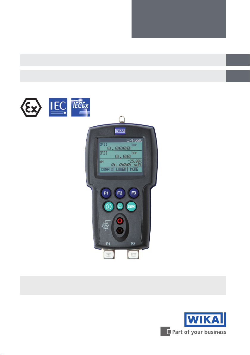
Intrinsically-safe hand-held pressure calibrator, model CPH65I0
Eigensicherer Hand-Held Druckkalibrator, Typ CPH65I0
GB
D
Intrinsically-safe hand-held pressure calibrator,
model CPH65I0-S2
Page 2

Operating instructions model CPH65I0 Page 3 - 50
GB
Betriebsanleitung Typ CPH65I0 Seite 51 - 97
D
© 2013 WIKA Alexander Wiegand SE & Co. KG
All rights reserved. / Alle Rechte vorbehalten.
®
WIKA
is a registered trademark in various countries.
®
WIKA
ist eine geschützte Marke in verschiedenen Ländern.
Prior to starting any work, read the operating instructions!
Keep for later use!
Vor Beginn aller Arbeiten Betriebsanleitung lesen!
Zum späteren Gebrauch aufbewahren!
2
WIKA operating instructions, model CPH65I0
14061681.02 03/2013 GB/D
Page 3

Contents
Contents
1. General information 4
2. Safety 5
Intended use
2.1
Personnel qualication
2.2
Additional safety instructions for instruments per ATEX
2.3
Special hazards
2.4
Labelling, safety marks
2.5
3. Specications 12
4. Design and function 17
Description
4.1
Scope of delivery
4.2
Pressure and electrical connections
4.3
Keypad
4.4
5. Transport, packaging and storage 20
6. Commissioning, operation 21
Calibrator display
6.1
Using the backlighting
6.2
Using of the "ZERO" function
6.3
Further menu controlled functions
6.4
Factory settings
6.5
Menu structure
6.6
Measuring pressure
6.8
Measuring current
6.8
Measuring temperature with a resistance thermometer
6.9
Performing a pressure switch test
6.10
Calibrating transmitters
6.11
MIN/MAX memory
6.12
7. Maintenance, cleaning and recalibration 44
8. Faults 46
9. Dismounting, return and disposal 47
10. Accessories 48
Appendix: EC Declaration of Conformity for model CPH65I0 49
11
17
17
18
19
21
23
23
25
29
32
34
35
36
37
39
44
GB
6
6
7
9
Declarations of conformity can be found online at www.wika.com.
14061681.02 03/2013 GB/D
3WIKA operating instructions, model CPH65I0
Page 4

1. General information
1. General information
■
The model CPH65I0 hand-held pressure calibrator described in the operating
GB
instructions has been manufactured using state-of-the-art technology.
All components are subject to stringent quality and environmental criteria during
production. Our management systems are certied to ISO 9001 and ISO 14001.
■
These operating instructions contain important information on handling the
instrument. Working safely requires that all safety instructions and work instructions
are observed.
■
Observe the relevant local accident prevention regulations and general safety
regulations for the instrument's range of use.
■
The operating instructions are part of the product and must be kept in the immediate
vicinity of the instrument and readily accessible to skilled personnel at any time.
■
Skilled personnel must have carefully read and understood the operating instructions
prior to beginning any work.
■
The manufacturer's liability is void in the case of any damage caused by using
the product contrary to its intended use, non-compliance with these operating
instructions, assignment of insuciently qualied skilled personnel or unauthorised
modications to the instrument.
■
The general terms and conditions contained in the sales documentation shall apply.
■
Subject to technical modications.
■
Factory calibrations / DKD/DAkkS calibrations are carried out in accordance with
international standards.
■
Further information:
- Internet address: www.wika.de / www.wika.com
- Relevant data sheet: CT 14.51
- Application consultant:
Tel.: (+49) 9372/132-9986
Fax: (+49) 9372/132-8767
E-Mail: testequip@wika.com
4 WIKA operating instructions, model CPH65I0
14061681.02 03/2013 GB/D
Page 5
1. General information / 2. Safety
Explanation of symbols
WARNING!
... indicates a potentially dangerous situation that can result in serious
injury or death, if not avoided.
CAUTION!
... indicates a potentially dangerous situation that can result in light
injuries or damage to equipment or the environment, if not avoided.
Information
... points out useful tips, recommendations and information for ecient
and trouble-free operation.
DANGER!
...identies hazards caused by electric power. Should the safety
instructions not be observed, there is a risk of serious or fatal injury.
GB
WARNING!
... indicates a potentially dangerous situation in the hazardous area that
can result in serious injury or death, if not avoided.
2. Safety
WARNING!
Before installation, commissioning and operation, ensure that the
appropriate hand-held pressure calibrator has been selected in terms of
measuring range, design and specic measuring conditions.
Non-observance can result in serious injury and/or damage to the
equipment.
Further important safety instructions can be found in the individual
chapters of these operating instructions.
14061681.02 03/2013 GB/D
5WIKA operating instructions, model CPH65I0
Page 6

2. Safety
2.1 Intended use
The model CPH65I0 intrinsically-safe hand-held calibrator can be used as a calibration
reference or in any application requiring high-accuracy pressure measurement.
GB
The instrument has been designed and built solely for the intended use described here,
and may only be used accordingly.
The technical specications contained in these operating instructions must be observed.
Improper handling or operation of the instrument outside of its technical specications
requires the instrument to be taken out of service immediately and inspected by an
authorised WIKA service engineer.
Handle electronic precision measuring instruments with the required care (protect from
humidity, impacts, strong magnetic elds, static electricity and extreme temperatures,
do not insert any objects into the instrument or its openings). Plugs and sockets must be
protected from contamination.
If the instrument is transported from a cold into a warm environment, the formation of
condensation may result in instrument malfunction. Before putting it back into operation,
wait for the instrument temperature and the room temperature to equalise.
The manufacturer shall not be liable for claims of any type based on operation contrary
to the intended use.
2.2 Personnel qualication
WARNING!
Risk of injury should qualication be insucient!
Improper handling can result in considerable injury and damage to
equipment.
■
The activities described in these operating instructions may only
be carried out by skilled personnel who have the qualications
described below.
■
Keep unqualied personnel away from hazardous areas.
6 WIKA operating instructions, model CPH65I0
14061681.02 03/2013 GB/D
Page 7

2. Safety
Skilled personnel
Skilled personnel are understood to be personnel who, based on their technical training,
knowledge of measurement and control technology and on their experience and
knowledge of country-specic regulations, current standards and directives, are capable
of carrying out the work described and independently recognising potential hazards.
Special operating conditions require further appropriate knowledge, e.g. of aggressive
media.
2.3 Additional safety instructions for instruments per ATEX
WARNING!
Non-observance of these instructions and their contents may result in
the loss of explosion protection.
Battery operation:
■
Use AA alkaline batteries only!
■
Only replace the batteries outside the hazardous area!
■
Only use permitted size AA alkaline batteries as described in the
following table.
GB
Permitted batteries
Battery manufacturer
(alkaline batteries - AA 1.5 V)
Duracell MN1500
Rayovac 815
Energizer E91
Panasonic AM3*
*model AM3 has been replaced by model LR6XWA
Temperature range:
■
14061681.02 03/2013 GB/D
Model
Permissible ambient temperature range: -10 ... +45 °C
7WIKA operating instructions, model CPH65I0
Page 8
GB
2. Safety
Connection values
Max. voltage Uo = DC 7.14 V
Max. current Io = 1.12 mA
Max. power Po = 2 mW
Max. eective internal capacitance Co = 240 µF
Max. eective internal inductance Lo = 1 H
Power supply circuit
Max. voltage Ui = DC 30 V
Max. current Ii = 80 mA
Max. power Pi = 750 mW
Max. eective internal capacitance Ci = 0 nF
Max. eective internal inductance Li = 0 mH
WARNING!
Further hazardous area safety instructions:
Observe the operating information and the relevant state regulations
concerning use in hazardous areas (e.g. EN IEC 60079-14).
The model CPH65I0 intrinsically-safe hand-held pressure calibrator has
been designed for use in hazardous areas. In these areas there is the
possibility of inammable or explosive gases being present.
The model CPH65I0 intrinsically-safe hand-held pressure calibrator has
been designed to be intrinsically safe. This means that connection with
other equipment that is in an intrinsically-safe circuit will not lead to arcs
capable of causing ignition, so long as the parameters are complied with.
Information/Approval for hazardous locations
WARNING!
Hazardous Areas
A hazardous area, as used in these operating instructions, refers to
an area made hazardous by the potential presence of ammable or
explosive vapours. These areas are also referred to as hazardous
locations.
8 WIKA operating instructions, model CPH65I0
14061681.02 03/2013 GB/D
Page 9
2. Safety
WARNING!
The replacement of components may compromise the explosion
protection. Service and repair must be carried out by the manufacturer.
2.4 Special hazards
WARNING!
Observe the information given in the applicable type examination
certicate and the relevant country-specic regulations for installation
and use in hazardous areas (e.g. IEC 60079-14, NEC, CEC).
Non-observance can result in serious injury and/or damage to
equipment.
For additional important safety instructions for instruments with ATEX
approval see chapter 2.3 "Additional safety instructions for instruments
per ATEX".
II 2 G Ex ia IIB T3 Gb (Ta = -10…+45 °C)
DEKRA 12ATEX 0146 X
Ex ia IIB T3 Gb (Ta = -10…+45 °C)
IECEx CSA 11.0019X
GB
WARNING!
■
■
■
■
■
■
■
■
14061681.02 03/2013 GB/D
Pressure sensors should only be mounted or dismounted when the
system is free from pressure.
Observe the working conditions in accordance with chapter
3 "Specications".
Always operate the pressure calibrator within its overload limits. See
chapter 3 "Specications".
Do not apply a voltage greater than the specied voltage to the
instrument. See chapter 3 "Specications".
Residual media on the dismounted calibrator and/or sensors can
result in a risk to persons, the environment and the equipment. Take
sucient precautionary measures.
Only use those accessories available from WIKA for the calibrator.
Make sure that the test probes never contact a voltage source while
the test cables are connected to the current terminals.
The measurement signal of the reference (or test sample) can be
inuenced by large electromagnetic eects and the display of the
signal may be lost completely.
9WIKA operating instructions, model CPH65I0
Page 10

GB
2. Safety
WARNING!
■
Do not use the calibrator if it is damaged. Before using the
instrument, check that there are no cracks or missing plastic parts on
the case. Pay particular attention to the insulation of the connectors.
■
The battery cover must be closed and locked in place before the
instrument is operated.
■
Remove the test cables from the instrument before opening the
battery compartment.
■
Inspect the test cables for damaged insulation or exposed metal.
Check the continuity of the leads. Damaged test leads should be
replaced before using the instrument.
■
When using test probes, keep ngers away from the test probe
contacts. Place ngers behind the nger guards on the test probes.
■
Do not use the instrument if it is not working properly. The instrument
protection might be compromised. If in doubt, have the instrument
checked.
■
Only use the instrument in classied areas for which the calibrator is
approved.
■
Disconnect test leads before changing to another measurement or
generation function.
■
To avoid false readings, replace the battery as soon as the battery
indicator appears.
■
Use the correct connection, the proper function and the correct
measuring range for measurements.
■
When screwing an adaptor onto the NPT thread of the calibrator, a
sealing material must also be used (e.g. PTFE tape).
■
When screwing on, use a spanner on the pressure connection for
xing to the calibrator, in order to avoid unnecessary stress on the
case.
10 WIKA operating instructions, model CPH65I0
14061681.02 03/2013 GB/D
Page 11
2. Safety
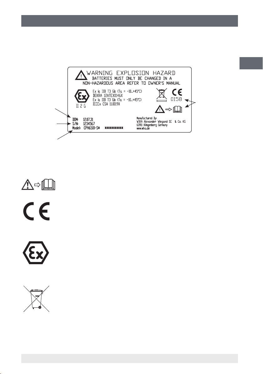
2.5 Labelling, safety marks
Product label
GB
Date of
manufacture
Serial number
1- or 2-channel
version
Explanation of symbols
Before mounting and commissioning the instrument, ensure you read the
operating instructions!
CE, Communauté Européenne
Instruments bearing this mark comply with the relevant European
directives.
ATEX European Explosion Protection Directive
(Atmosphère = AT, explosible = EX)
Instruments bearing this mark comply with the requirements of the
European directive 94/9/EC (ATEX) on explosion protection.
For an explanation
of symbols, see
below
This marking on the instruments indicates that they must not be
disposed of in domestic waste. The disposal is carried out by return to
the manufacturer or by the corresponding municipal authorities (see
directive 2002/96/EC).
14061681.02 03/2013 GB/D
11WIKA operating instructions, model CPH65I0
Page 12

3. Specications
3. Specications
Sensor technology
GB
Measuring range mbar
Overpressure limit mbar 70 200 700 1,000
Accuracy % FS 0.1 0.05 0.035
Measuring range bar -1 ... +1
Overpressure limit bar 2 4 2 4
Accuracy % FS 0.025
Measuring range bar 0 ... 3.5
Overpressure limit bar 13 13 13 40
Accuracy % FS 0.025
Measuring range bar 0 ... 35
Overpressure limit bar 70 200 200 400
Accuracy % FS 0.025
Measuring range bar 0 ... 350 0 ... 700
Overpressure limit bar 700 1,000
Accuracy % FS 0.035
Measuring range bar abs. 0 ... 1 0 ... 2 0 ... 7 0 ... 10 0 ... 20
Overpressure limit bar abs. 2 4 13 13 40
Accuracy % FS 0.025
Measuring range
Overpressure limit mbar di. 70 200 700
Accuracy % FS 0.1 0.05 0.035
Measuring range
Overpressure limit mbar di. 4,000 7,000 10,000
Accuracy % FS 0.025
Type of pressure Relative pressure, absolute pressure, vacuum and dierential pressure
Pressure connection ⅛ NPT female (incl. adapter ⅛ NPT male to G ½ B male)
Pressure medium all liquids and gases which are compatible with 316 SS stainless steel
Resolution 5-digit
Current
Measuring range 0 … 24 mA
Resolution 1 µA
Accuracy 0.015 % of measured value ±2 µA
Temperature
Measuring range -40 … +150 °C
Resolution 0.01 °C
Accuracy 0.015 % of measured value ±20 mΩ, or 0.2 °C for complete measuring chain
1) Non isolated: Only use the pressure measuring ranges marked in this way with clean and non-corrosive gases.
2) Pressure measurement possible in vacuum range to -1 bar.
3) For dierential pressure sensors with a measuring range of 25 mbar, the maximum static pressure is limited to 70 mbar. For the
measuring ranges 70, 350, 2,000, 3,500 and 7,000 mbar the static pressure is limited to a maximum of 10 bar.
4) The dierential pressure sensor is only possible with the CPH65I0-S1 (1-channel version). Both pressure connections for the
dierential pressure measurement are located at the bottom of the calibrator.
5) Adapter not included in delivery for North America.
1)
mbar di.
mbar di.
-25 ... +25 -70 … +70
1)
-1 ... +2 1)0 … 1
2)
0 ... 7
2)
0 ... 70 0 ... 100 0 ... 200
1) 3)
0 ... 25 0 ... 70 0 ... 350
1) 3)
0 ... 2,000 0 ... 3,500 0 ... 7,000
2)
-350 ... +350
0 ... 10
(Pt100 resistance thermometer and CPH65I0)
1)
2)
-500 … +500
1)
0 ... 2
0 ... 20
5)
2)
4)
1)
12 WIKA operating instructions, model CPH65I0
14061681.02 03/2013 GB/D
Page 13

3. Specications
Base instrument
Measuring inputs 1 input for CPH65I0-S1
Pressure connection ⅛ NPT female thread
Pressure medium
Temperature compensation 15 … 35 °C
Temperature coecient 0.002 % of the span/°C outside of the 15 ... 35 °C temperature range
Pressure units psi, bar, mbar, kPa, MPa, kg/cm², mmH
Indicator
Display 5-digit display; large backlit screen for the display of up to three
Voltage supply
Power supply DC 6 V, 4 x 1.5 V AA alkaline batteries
Battery life > 35 hours
Permissible ambient conditions
Operating temperature -10 ... +45 °C
Storage temperature -20 ... +60 °C
Relative humidity 5 ... 95 % r. h. (non-condensing)
Case
Material stainless steel and plastic
Dimensions see technical drawing
Weight approx. 570 g
Non isolated: Only use the pressure measuring ranges marked in this way with clean and non-corrosive gases. (See sensor
1)
table)
2 inputs for CPH65I0-S2
all liquids and gases which are compatible with 316 SS stainless steel
O (4 °C), mmH2O (20 °C),
cmH
O (4 °C), cmH2O (20 °C), inH2O (4 °C), inH2O (20 °C),
2
inH
O (60 °F), mmHg (0 °C), inHg (0 °C), ft H2O (60 °F)
2
measurement parameters
2
GB
1)
Approvals and certicates
CE conformity
EMC directive 2004/108/EC, EN 61326 emission (group 1, class B) and interference
immunity (portable measurement equipment)
ATEX directive 94/9/EC, category 2G, ignition protection type Ex ia IIB T3 Gb
Certicate
Calibration Standard: 3.1 calibration certicate per EN 10204
Option: DKD/DAkkS calibration certicate
Approvals and certicates, see website
14061681.02 03/2013 GB/D
13WIKA operating instructions, model CPH65I0
Page 14

3. Specications
Types of explosion protection
ATEX directive 94/9/EC, category 2G, ignition protection type Ex ia IIB T3 Gb
GB
IECEx Ex ia IIB T3 Gb (Ta = -10…+45 °C)
Connection values
Max. voltage Uo = DC 7.14 V
Max. current Io = 1.12 mA
Max. power Po = 2 mW
Max. eective internal capacitance Co = 240 µF
Max. eective internal inductance Lo = 1 H
Power supply circuit
Max. voltage Ui = DC 30 V
Max. current Ii = 80 mA
Max. power Pi = 750 mW
Max. eective internal capacitance Ci = 0 nF
Max. eective internal inductance Li = 0 mH
LEMO plug connector only for use with LTP100A RTD sensor
For further specications see WIKA data sheet CT 14.51 and the order documentation.
Available measuring ranges and resolutions
II 2 G Ex ia IIB T3 Gb (Ta = -10…+45 °C)
DEKRA 12ATEX 0146 X
IECEx CSA 11.0019X
Measuring ranges and factors
Measuring range in bar
Unit Conversion factor
psi 1 0.4000 1.0000 5.0000 7.2000 15.000 30.000
bar 0.06894757 0.0276 0.0689 0.3447 0.4964 1.0342 2.0684
mbar 68.94757 27.579 68.948 344.74 496.42 1,034.2 2,068.4
kPa 6.894757 2.7579 6.8948 34.474 49.642 103.42 206.84
Mpa 0.00689476 0.0028 0.0069 0.0345 0.0496 0.1034 0.2068
kg/cm² 0.07030697 0.0281 0.0703 0.3515 0.5062 1.0546 2.1092
mmHg (0 °C) 51.71507 20.686 51.715 258.58 372.35 775.73 1,551.5
inHg (0 °C) 2.03603 0.8144 2.0360 10.180 14.659 30.540 61.081
O (4 °C) 70.3089 28.124 70.309 351.54 506.22 1,054.6 2,109.3
cmH
2
O (20 °C) 70.4336 28.173 70.434 352.17 507.12 1,056.5 2,113.0
cmH
2
O (4 °C) 703.089 281.24 703.09 3,515.4 5,062.2 10,546 21,093
mmH
2
O (20 °C) 704.336 281.73 704.34 3,521.7 5,071.2 10,565 21,130
mmH
2
O (4 °C) 27.68067 11.072 27.681 138.40 199.30 415.21 830.42
inH
2
O (20 °C) 27.72977 11.092 27.730 138.65 199.65 415.95 831.89
inH
2
O (60 °F) 27.70759 11.083 27.708 138.54 199.49 415.61 831.23
inH
2
O (60 °F) 2.308966 0.9236 2.3090 11.545 16.625 34.634 69.269
ftH
2
14 WIKA operating instructions, model CPH65I0
0 ... 0.025 0 ... 0.07 0 ... 0.35 0 ... 0.5 0 ... 1 1)0 ... 2
2)
14061681.02 03/2013 GB/D
Page 15

3. Specications
Measuring ranges and factors
Measuring range in bar
0 ... 3.5 0 ... 7
Unit Conversion factor
psi 1 50.000 100.00 150.00 300.00 500.00
bar 0.06894757 3.4474 6.8948 10.342 20.684 34.474
mbar 68.94757 3,447.4 6,894.8 10,342 20,684 34,474
kPa 6.894757 344.74 689.48 1,034.2 2,068.4 3,447.4
Mpa 0.00689476 0.3447 0.6895 1.0342 2.0684 3.4474
kg/cm² 0.07030697 3.5153 7.0307 10.546 21.092 35.153
mmHg (0 °C) 51.71507 2,585.8 5,171.5 7,757.3 15,515 25,858
inHg (0 °C) 2.03603 101.80 203.60 305.40 610.81 1,018.0
O (4 °C) 70.3089 3,515.4 7,030.9 10,546 21,093 35,154
cmH
2
O (20 °C) 70.4336 3,521.7 7,043.4 10,565 21,130 35,217
cmH
2
O (4 °C) 703.089 35,154 70,309 --
mmH
2
mmH2O (20 °C) 704.336 35,217 70,434 -inH2O (4 °C) 27.68067 1,384.0 2,768.1 4,152.1 8,304.2 13,840
O (20 °C) 27.72977 1,386.5 2,773.0 4,159.5 8,318.9 13,865
inH
2
O (60 °F) 27.70759 1,385.4 2,770.8 4,156.1 8,312.3 13,854
inH
2
O (60 °F) 2.308966 115.45 230.90 346.34 692.69 1,154.5
ftH
2
Measuring ranges and factors
Measuring range in bar
Unit Conversion factor
psi 1 1,000.0 1,500.0 3,000.0 5,000.0 10,000
bar 0.06894757 68.948 103.42 206.84 344.74 689.48
mbar 68.94757 68,948 -kPa 6.894757 6,894.8 10,342 20,684 34,474 68,948
Mpa 0.00689476 6.8948 10.342 20.684 34.474 68.948
kg/cm² 0.07030697 70.307 105.46 210.92 351.53 703.07
mmHg (0 °C) 51.71507 51,715 77,573 -inHg (0 °C) 2.03603 2,036.0 3,054.0 6,108.1 10,180 20,360
O (4 °C) 70.3089 70,309 --
cmH
2
cmH2O (20 °C) 70.4336 70,434 -mmH2O (4 °C) 703.089 -mmH2O (20 °C) 704.336 -inH2O (4 °C) 27.68067 27,681 41,521 83,042 -inH2O (20 °C) 27.72977 27,730 41,595 83,189 -inH2O (60 °F) 27.70759 27,708 41,561 83,123 -ftH2O (60 °F) 2.308966 2,309.0 3,463.4 6,926.9 11,545 23,090
1) This data is also valid for the measuring ranges -1 ... +1 bar and 0 ... 1 bar abs.
2) This data is also valid for the measuring ranges -1 ... +2 bar and 0 ... 2 bar abs.
3) This data is also valid for the measuring ranges 0 ... 7 bar abs., 0 ... 10 bar abs. and 0 ... 20 bar abs.
4) Due to the limited screen resolution, no values can be displayed here. The resolution is limited to 5 digits.
0 ... 70 0 ... 100 0 ... 200 0 ... 350 0 ... 700
4)
4)
3)
0 ... 10 3)0 ... 20 3)0 ... 35
4)
4)
4)
4)
4)
4)
--
4)
--
4)
--
4)
4)
--
4)
--
4)
--
4)
--
4)
--
4)
--
4)
--
4)
--
4)
--
4)
--
4)
--
4)
--
4)
4)
4)
4)
--
4)
--
4)
--
4)
--
4)
--
4)
--
4)
--
4)
--
4)
--
4)
--
4)
--
GB
14061681.02 03/2013 GB/D
15WIKA operating instructions, model CPH65I0
Page 16
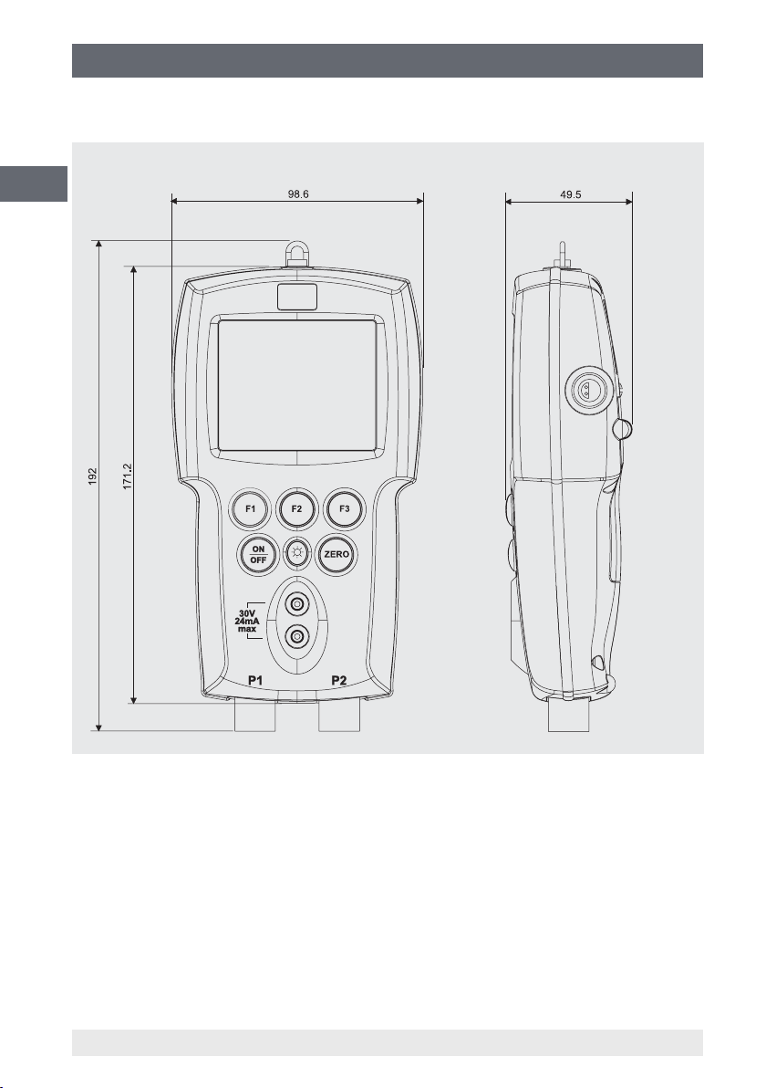
3. Specications
Dimensions in mm
GB
Front view Side view, right
16 WIKA operating instructions, model CPH65I0
14061681.02 03/2013 GB/D
Page 17

4. Design and function
4. Design and function
4.1 Description
The model CPH65I0-S1/S2 intrinsically-safe hand-held pressure calibrator has been
designed so that it is simple to handle, but is also a very versatile pressure calibrator.
The two internal reference pressure sensors, combined with current input, pressure
switch function and a resistance thermometer, enable the CPH65I0-S1/S2 to calibrate
practically any pressure instrument.
The model CPH65I0-S1 intrinsically-safe hand-held pressure calibrator has a single
integrated pressure sensor; the model CPH65I0-S2 intrinsically-safe hand-held
pressure calibrator has two integrated pressure sensors. The CPH65I0-S1 uses
connection P1 for all pressure measurements. Connection P2 is only used in the
CPH65I0-S2. Thus, the pressure-related menu selection for the CPH65I0-S1 is limited
to connection P1 only. All other CPH65I0-S1 features and functions are identical to the
CPH65I0-S2.
4.2 Scope of delivery
■
Model CPH65I0-S1/S2 intrinsically-safe hand-held pressure calibrator
■
Operating instructions
■
Test cables
■
4 AA alkaline batteries
■
1 x adapter 1/8 NPT male to G 1/2 B male per pressure connection
■
1x PTFE tape
■
3.1 calibration certicate per DIN EN 10204
1)
GB
1) Adapter not included in delivery for North America
Cross-check scope of delivery with delivery note.
14061681.02 03/2013 GB/D
17WIKA operating instructions, model CPH65I0
Page 18
4. Design and function
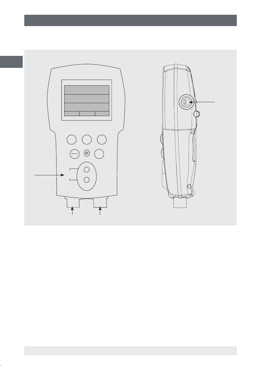
4.3 Pressure and electrical connections
Front view Side view, right
GB
CPH65I0
[P1]
mA -25.00%
RTD
72.50 °F
CONF
UPPER
F1 F2 F3
psi
0.000
0.000 mA
MORE
4
ON
OFF
30V
3
24mA
max
P1 P2
ZERO
1 2
1) P1 pressure connection
Connection for internal sensor, P1
2) P2 pressure connection
Connection for internal sensor, P2
3) Input connection
Electrical connections for current and switch test
4) Resistance thermometer
Connection for external resistance thermometer
18 WIKA operating instructions, model CPH65I0
14061681.02 03/2013 GB/D
Page 19
4. Design and function
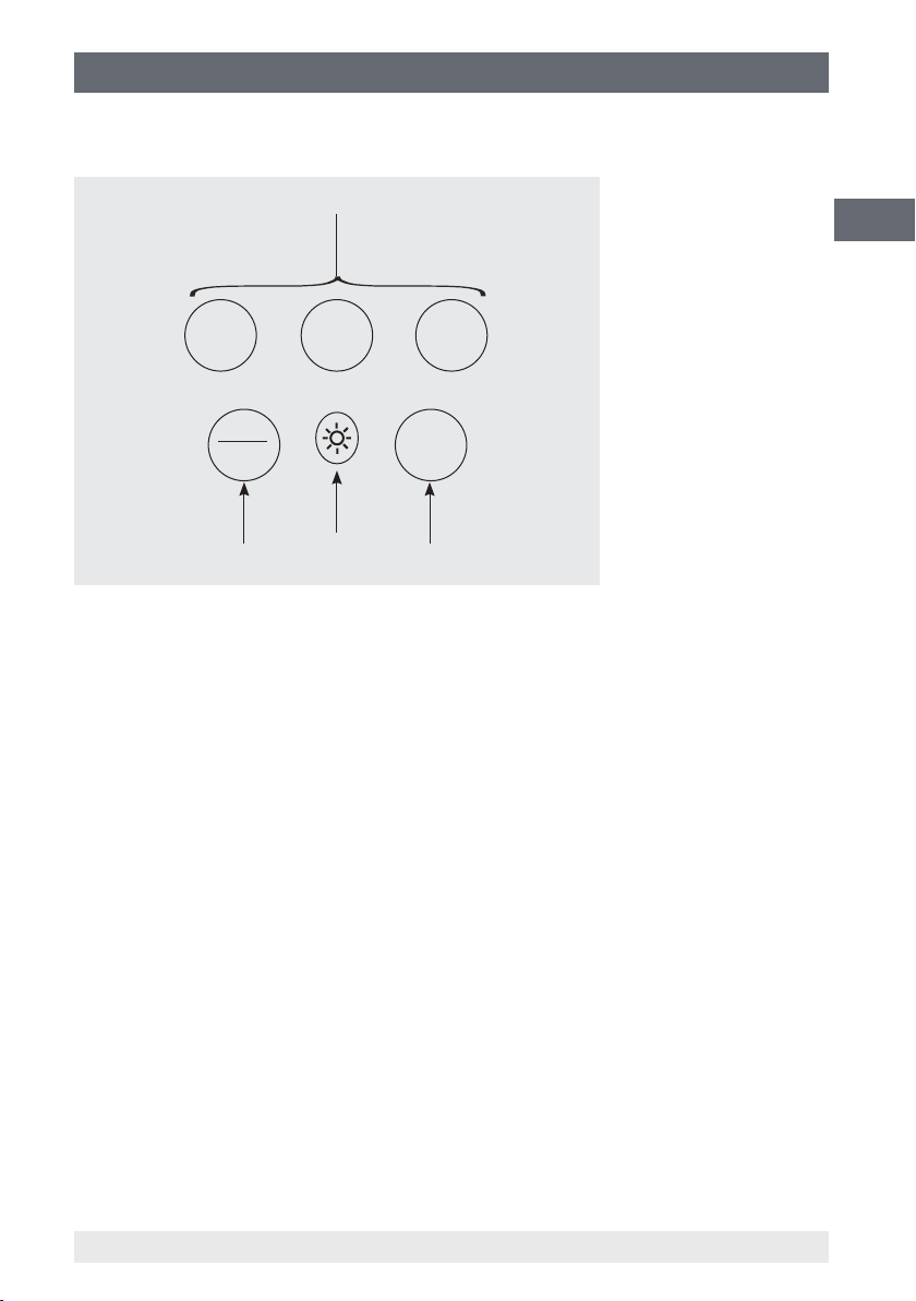
4.4 Keypad
F1 F2 F3
1
GB
ON
OFF
2 4
1) Function keys
Conguration of the instruments
2) ON/OFF button
Turning the instrument on and o
3) Backlighting
Turning the backlighting on and o
4) ZERO key
Zeroing of the pressure measurement
3
ZERO
14061681.02 03/2013 GB/D
19WIKA operating instructions, model CPH65I0
Page 20

5. Transport, packaging and storage
5. Transport, packaging and storage
5.1 Transport
GB
Check hand-held pressure calibrator for any damage that may have been caused by
transport.
Obvious damage must be reported immediately.
5.2 Packaging
Do not remove packaging until just before mounting.
Keep the packaging as it will provide optimum protection during transport (e.g. change
in installation site, sending for repair).
5.3 Storage
Permissible conditions at the place of storage:
■
Storage temperature: -20 ... +60 °C
■
Relative humidity: 5 ... 95 % r. h. (non-condensing)
Avoid exposure to the following factors:
■
Direct sunlight or proximity to hot objects
■
Mechanical vibration, mechanical shock (putting it down hard)
■
Soot, vapour, dust and corrosive gases
Store the hand-held pressure calibrator in its original packaging in a location that fulls
the conditions listed above. If the original packaging is not available, pack and store the
instrument as described below:
1. Wrap the instrument in an antistatic plastic lm.
2. Place the instrument, along with shock-absorbent material, in the packaging.
WARNING!
Before storing the instrument (following operation), remove any residual
media. This is of particular importance if the medium is hazardous to
health, e.g. caustic, toxic, carcinogenic, radioactive, etc.
20 WIKA operating instructions, model CPH65I0
14061681.02 03/2013 GB/D
Page 21
6. Commissioning, operation
6. Commissioning, operation
As soon as the model CPH65I0 hand-held pressure calibrator is turned on, by pressing
the ON/OFF key, it will go through a short self-test routine. During this routine, the
display shows the current rmware version, auto-shutdown status and the measuring
range of the internal pressure sensor. The calibrator requires a maximum of 5 minutes
warm-up to reach its specied accuracy. Large changes in ambient temperature may
make a longer warm-up period necessary. The pressure display of the calibrator should
be zeroed before starting the pressure calibration. See chapter 6.3 "Use of the "ZERO"
function".
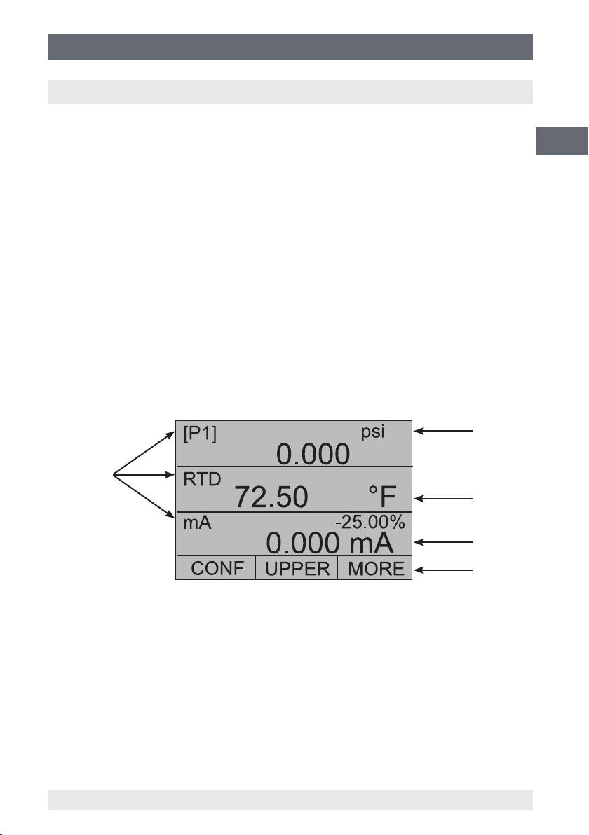
6.1 Calibrator display
The calibrator's display consists of two sectors: The menu bar (located along the
bottom of the screen) is used to access the menu system. The main display (the rest of
the display) consists of up to three sub-sectors for the measurement activities. These
sub-sectors will be referred to as the UPPER, MIDDLE and LOWER displays in this
document.
Figure 1 shows the location of the dierent display elds, which are described in the
following table.
1
GB
5
Figure 1: Display
1) Pressure units
Indication of the pressure unit (selectable from 16 pressure units)
2) Units
Indication of the measuring unit
3) Display of the span
Indication of 4 ... 20 mA span (only with mA measurement)
4) Menu list
5) Primary parameters
Indication of the current measured parameters
14061681.02 03/2013 GB/D
2
3
4
21WIKA operating instructions, model CPH65I0
Page 22

6. Commissioning, operation
6.1.1 Main menu Functionality
There are three options in this menu: "CONFIG", {active display} and "MORE". The
main menu is the home menu for the menu display.
GB
6.1.1.1 Setting the {active display} parameters
The {active display} is displayed via the middle option in the menu in the main display.
Pressing the F2 key switches between the {active display}.
6.1.1.2 Setting the {active display} parameters
In order to set the {active display} parameters, select the "CONFIG" option and open
the conguration menu.
The "SELECT" option switches between the available choices for each parameter.
Since voltage, current and switch-test modes all use the same leads, two of these
functions cannot be used concurrently. The ability to select certain functions is limited
and dependent upon what is already selected in the other display sector. The "NEXT"
option is used to switch to the second parameter.
Only the resistance thermometer and pressure modes have a second parameter.
Resistance thermometers can be displayed in Celsius or Fahrenheit and for pressure
there are 16 dierent units.
Within any single display sector, the following modes are available:
P[1] = left integrated pressure sensor
P[2] = right integrated pressure sensor (only for CPH65I0-S2)
P[1] ST = switch test with left integrated sensor.
P[2] ST = switch test with right integrated sensor (only for CPH65I0-S2)
mA measurement = current measurement
RTD = resistance thermometer (in the event a resistance thermometer
is connected)
22 WIKA operating instructions, model CPH65I0
14061681.02 03/2013 GB/D
Page 23

6. Commissioning, operation
The following table shows which functions are available concurrently.
An "--" in a column indicates that the mode in the active display will not be available for
selection if the mode in that row is in use in any other display sector.
Active display
P[1] P[2] P[1] ST P[2] ST mA RTD
P[1]
P[2]
P[1] ST
P[2] ST
mA
Other displays
RTD
6.1.1.3 Accessing other menus
In order to access further menus, select the "MORE" option in the main menu. See
chapter 6.6 "Menu structure".
6.2 Using the backlighting
The backlight has its own dedicated button. The light is toggled on and o when the
button is pressed.
-- -- --
-- -- --
-- --
GB
6.3 Using the "ZERO" function
When the ZERO key is pressed, the calibrator will zero the {active display}, as long as
a pressure mode is selected and the pressure is within the zero limit. The zero limits are
within 5 % of the full scale range of the selected sensor. If the display indicates "OL" the
zero function will not operate.
The ZERO key is only used for pressure.
14061681.02 03/2013 GB/D
23WIKA operating instructions, model CPH65I0
Page 24
6. Commissioning, operation
6.3.1 Internal relative pressure sensor
When a relative pressure sensor is selected in the {active display} and the ZERO key
is pressed, the calibrator subtracts the current displayed reading from the output value.
The zero limits are within 5 % of the full scale range of the selected sensor. If the display
GB
indicates "OL" the zero function will not operate.
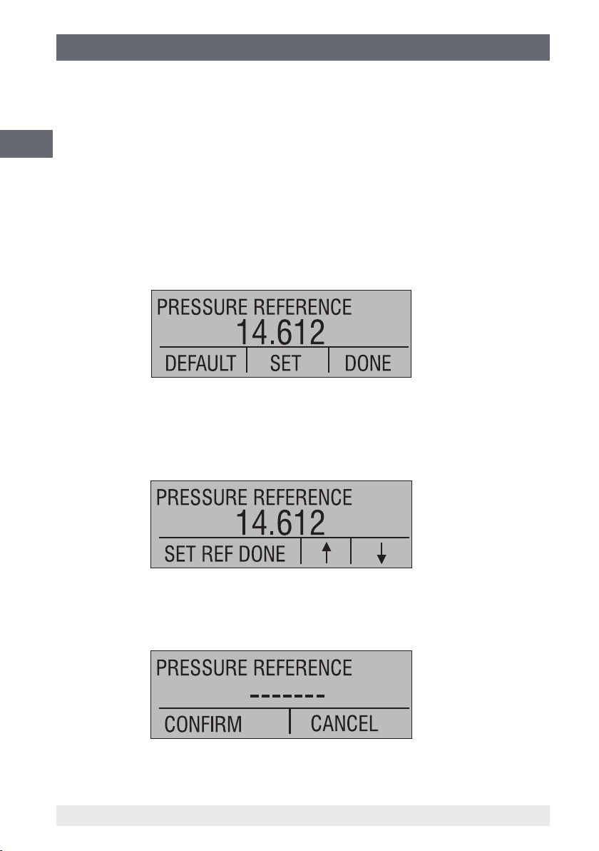
6.3.2 Internal absolute pressure sensor
If an absolute pressure sensor is selected in the {active display} and the ZERO button
is pressed, the calibrator instructs the user to enter the reference pressure value with
"SET" or to reset with "DEFAULT". The reference instrument should be at least four
times as accurate as the absolute pressure sensor of the CPH65I0.
If "SET" is selected, the calibrator prompts the user to enter the barometric reference
pressure. The arrow keys, F2 and F3, can be used for this. The sensor connection
should be open (vented) to atmosphere while performing this procedure.
If, alternatively, "DEFAULT" is selected, the reversion to the factory setting must be
accepted with "CONFIRM" or the action aborted with "CANCEL".
24 WIKA operating instructions, model CPH65I0
14061681.02 03/2013 GB/D
Page 25
6. Commissioning, operation
6.4 Further menu controlled functions
There are ten submenus that can be accessed through the "MORE" option of the main
menu. A submenu contains three options. The rst option is unique to this function. The
second and third options of a submenu are always the same.
The "NEXT" option leads to the next submenu and the "DONE" option returns one to
the home menu.
With the last submenu the "NEXT" option returns to the home menu. The detailed menu
structure can be seen in 6.6 "Menu structure".
Note on naming:
If a 'Submenu' has further subdivisions, from now on it will be referred to as {function}
main menu. The "CONTRAST" submenu, for example, will be referred to as the
"CONTRAST" main menu. Otherwise it will be referred to as the {function} menu.
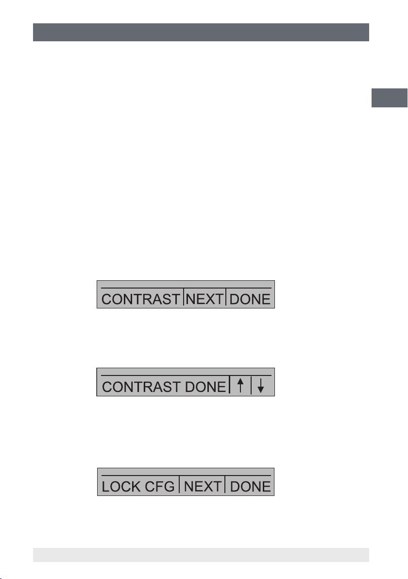
6.4.1 Setting the contrast
From the CONTRAST main menu, choose the "CONTRAST" option in order to access
the "Setting the contrast" menu.
GB
Use the F2 and F3 keys to set the display contrast to the desired strength and then use
the "DONE" option to return to the home menu.
6.4.2 Locking and unlocking congurations
Use the "LOCK CFG" or "UNLOCK CFG" option of the conguration lock menu
respectively to lock or unlock the display conguration.
14061681.02 03/2013 GB/D
25WIKA operating instructions, model CPH65I0
Page 26
6. Commissioning, operation
When the "LOCK CFG" option is chosen, the menu display returns home and the
"CONFIG" option on the main menu indicates that it is locked. Also, all other menus are
locked with the exception of the "CONTRAST" and "UNLOCK CFG" menus. When the
"UNLOCK CFG" option is chosen, the conguration is unlocked and the menu display
GB
continues to the next submenu.
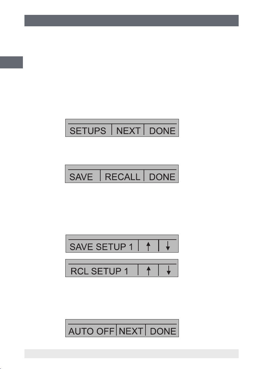
6.4.3 Saving and recalling settings
The calibrator automatically saves the current setting for recall on power-up. In addition,
ve settings can be accessed through the "SETUPS" menu. Select the "SETUPS"
option from the submenu.
"SAVE" to save the setting, "RECALL" to recall the setting or "DONE" to return home.
If "SAVE" or "RECALL" is selected, use the arrow keys to select the setting location.
Then use the "SAVE" option to store the current setting into the selected location or the
"RECALL" option to recall the setting stored in the selected location. The display menu
will automatically return home.
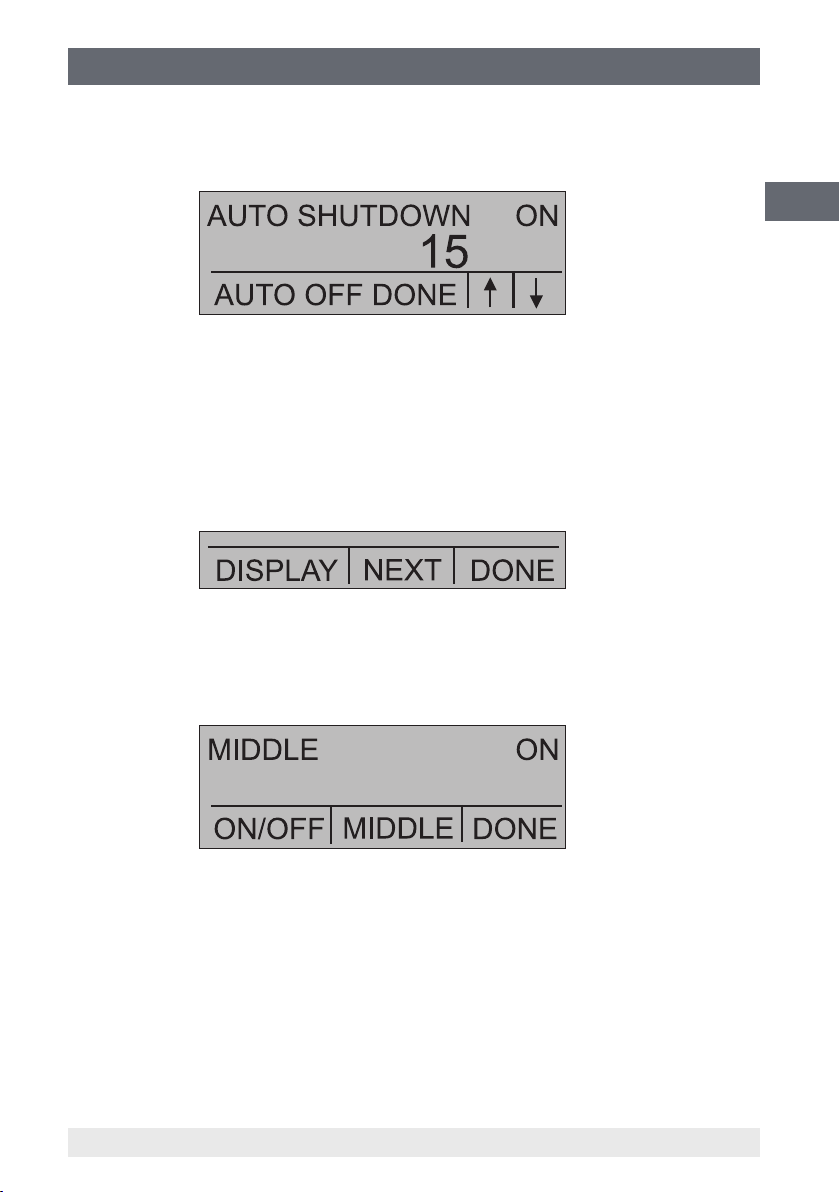
6.4.4 Setting auto shut-o parameters
The calibrator will switch itself o after a specied time; this function can also be
deactivated. Use the "AUTO OFF" option to set the auto shut-o parameters.
26 WIKA operating instructions, model CPH65I0
14061681.02 03/2013 GB/D
Page 27
6. Commissioning, operation
Use the F2 and F3 keys to select the time after which the calibrator will turn itself o, or
disable the auto shut-o by scrolling down to "0".
Use the "AUTO OFF DONE" option to set the parameters and return home. The auto
shut-o time is reset whenever a key is pressed.
6.4.5 Activating and deactivating a display
Use the "DISPLAY" option on the 'Display selection' main menu to access the display
activation menu.
The F2 key can be used to select the desired display. The "ON/OFF" option switches
the selected display on or o. The selected display and the current status "ON/OFF" are
shown in the lower display.
GB
Select the "DONE" option to save the changes and return home. When a display
is deactivated its conguration is retained. As soon as the display is activated, the
conguration is checked against the congurations of the other currently-active displays.
If there is any conict between congurations, the recalled display’s conguration is
modied to avoid the conict. If all three displays are deactivated the lower display will
switch on automatically.
14061681.02 03/2013 GB/D
27WIKA operating instructions, model CPH65I0
Page 28
6. Commissioning, operation
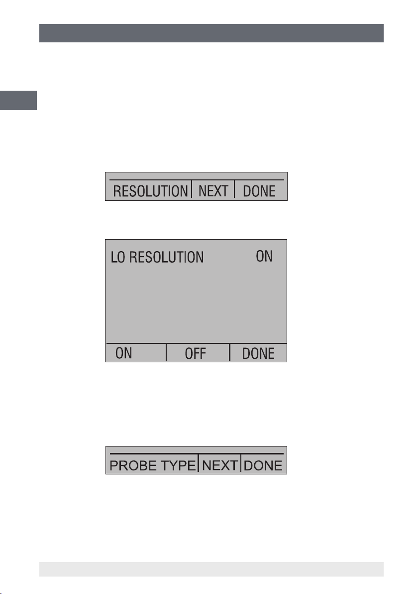
6.4.6 Reduced screen resolution
Due to the high accuracy of the CPH65I0, the measured value is displayed with a higher
resolution. In some cases, this is a disadvantage. For this, the CPH65I0 has a function
for lowering the display resolution. This function removes the last digit.
GB
In order to switch the function on or o, perform the following:
With the calibrator switched on, press the F3 key in order to activate the "MORE"
option. Press the "NEXT" key until "RESOLUTION" appears in the left-hand text eld.
Then press the F1 key to activate the function.
Select "ON" or "OFF" in order to switch the lower display resolution on or o.
Use "DONE" in order to return to the home menu.
6.4.7 Setting the resistance thermometer probe
Use the "PROBE TYPE" option of the 'RTD Probe Type' main menu to access the
menu for resistance thermometer probe selection.
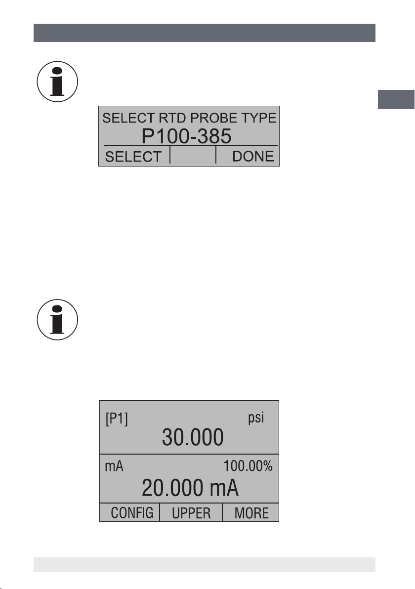
There are four types of resistance thermometers: "P100-385", "P100-392",
"P100-JIS" and "CUSTOM". With "CUSTOM", custom resistance thermometers
can be selected. Use the "SELECT" option to select the desired probe type and the
"DONE" option to store the change and return home.
28 WIKA operating instructions, model CPH65I0
14061681.02 03/2013 GB/D
Page 29
6. Commissioning, operation
The default resistance thermometer type is "PT100-385" (Pt100-385).
6.4.8 Damping
Damping can be turned ON or OFF using the "DAMPING" menu selection. As soon as
the damping function is switched ON, the calibrator displays the running average of the
last ten measurements. The calibrator makes approximately three readings per second.
6.5 Factory settings
The calibrator is delivered with ve commonly-used factory settings. These settings are
shown below.
Any of these settings can be changed and saved by the user.
GB
Setting 1:
The upper display is set to [P1] mode and the middle is set to "mA"; the lower is o.
14061681.02 03/2013 GB/D
29WIKA operating instructions, model CPH65I0
Page 30
6. Commissioning, operation
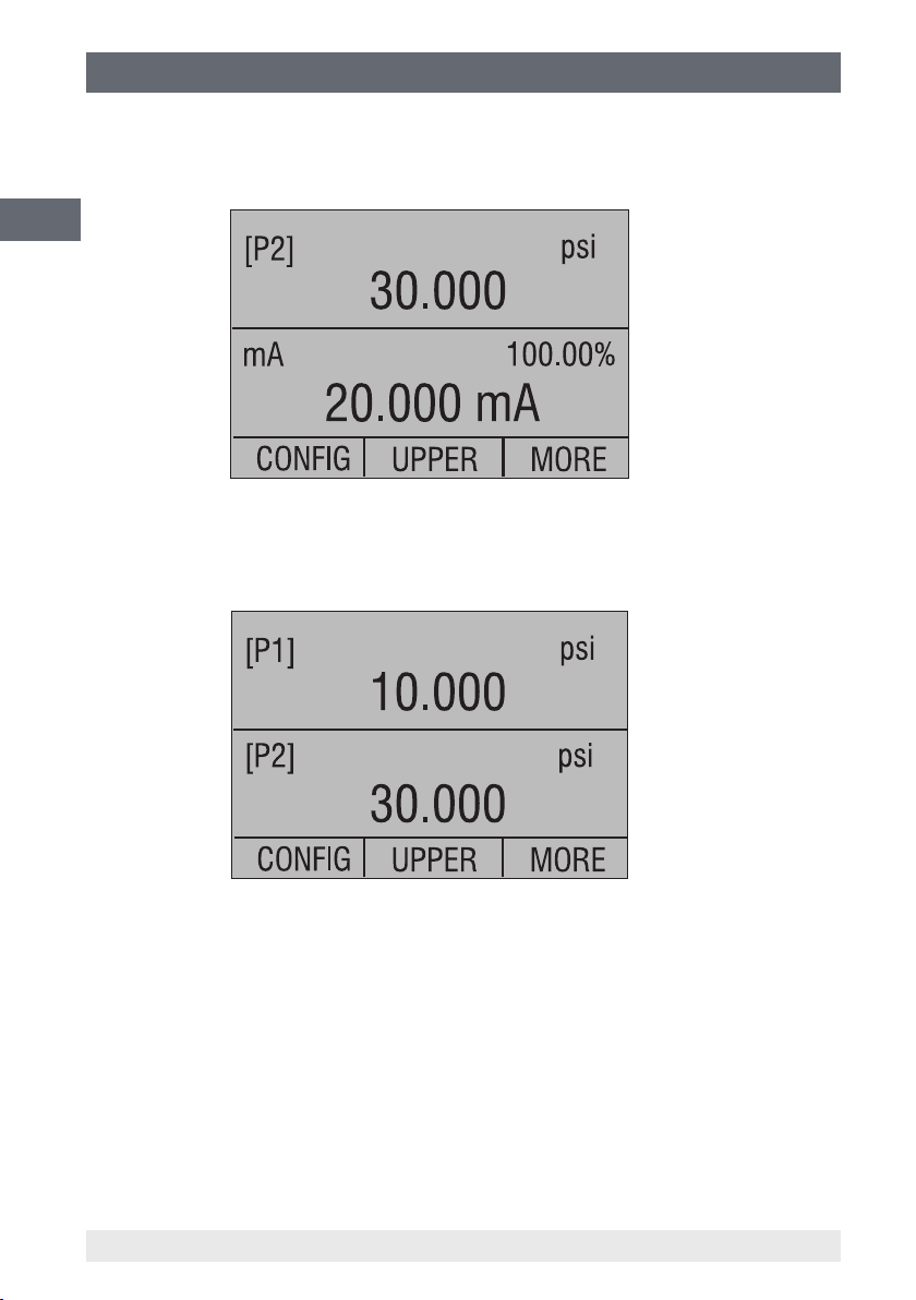
Setting 2:
The upper display is set to [P2] mode and the middle is set to "mA"; the lower is o.
GB
Setting 3:
The upper display is set to [P1] mode and the middle is set to [P2]; the lower is o.
30 WIKA operating instructions, model CPH65I0
14061681.02 03/2013 GB/D
Page 31

6. Commissioning, operation
Setting 4:
The upper display is set to [P1] "SWITCH TEST" all other displays are o.
Setting 5:
The upper display is set to [P1], the middle display is set to [P2] and the lower display is
set to "RTD".
GB
14061681.02 03/2013 GB/D
31WIKA operating instructions, model CPH65I0
Page 32

6. Commissioning, operation
6.6 Menu structure
GB
32 WIKA operating instructions, model CPH65I0
14061681.02 03/2013 GB/D
Page 33

6. Commissioning, operation
GB
14061681.02 03/2013 GB/D
33WIKA operating instructions, model CPH65I0
Page 34

6. Commissioning, operation
6.7 Measuring pressure
For pressure calibration, connect the calibrator with an appropriate adapter. Select the
pressure setting for the display being used. The calibrator is equipped with one or two
internal reference pressure sensors.
GB
Choose a sensor that is suitable for the pressure range and accuracy.
CAUTION!
Pressure sensors may be damaged and/or injuries may occur to
the personnel due to improper application of pressure. For a better
understanding with respect to overpressure and burst pressure, follow
the specications laid down in these operating instructions (see chapter
3 "Specications"). Vacuum should not be applied to any gauge pressure
sensor.
The calibrator display will indicate "OL" when an inappropriate pressure
is applied. As soon as "OL" is observed on any pressure display, the
pressure should be reduced immediately to prevent damage or possible
physical injury. "OL" is displayed if the pressure exceeds 110 % of the
nominal range of the sensor or if a vacuum in excess of 140 mbar (2 psi)
is applied on a gauge pressure sensor.
Valve
Figure 2: Pressure measurement
34 WIKA operating instructions, model CPH65I0
14061681.02 03/2013 GB/D
Page 35

6. Commissioning, operation
In order to protect the sensor from damage, the calibrator displays "OL"
[Overload] as soon as the applied pressure exceeds 120 % of the
complete measuring range.
In order to ensure the accuracy of the calibrator, it is necessary to reset
the calibrator to zero before a calibration.
6.7.1 Media compatibility
Most of the calibrator measuring ranges include a sensor that is isolated from the
medium in order to eliminate any contamination (observe chapter 3 "Specications").
If possible, use clean dry air. As this is not always possible, it must be ensured that the
medium is compatible with nickel-plated brass and stainless steel.
6.8 Measuring current
WARNING!
Observe the connection parameters prior to making a connection to the
instrument.
To measure current, use the input terminals on the front of the calibrator. Select the
mA function on the lower display. Current is measured in mA and percentage of the
measuring range. The measuring range on the calibrator is set to 0 % at 4 mA and
100 % at 20 mA.
GB
Example:
If the current measured is displayed as 75 %, then the value is 16 mA.
The display will indicate "OL" when the measured current exceeds the
nominal range of current measurement (24 mA).
4 ... 20 mA
14061681.02 03/2013 GB/D
Test item
35WIKA operating instructions, model CPH65I0
Page 36

6. Commissioning, operation
6.9 Measuring temperature with a resistance thermometer
For temperature measurement, select the function "RTD" on one of the displays.
The correct resistance thermometer must be used. There are four types of resistance
thermometer supported: "P100-385", "P100-392", "P100-JIS" and "CUSTOM".
GB
The factory default type is "P100-385", so if the CPH65I0 is being used
with a WIKA Pt100 you do not have to reset the resistance thermometer
type.
The WIKA Pt100 needs only to be connected to the CPH65I0 and the measured
temperature will immediately be displayed.
The display will indicate "OL" if the measured temperature is outside
the nominal measurement range of the resistance thermometer (below
-40 °C or above +150 °C).
CAUTION!
Only specic thermometer types are permitted (as dened in
chapter 2.3). It is recommended that those accessories available from
WIKA are used.
Figure 3: CPH65I0 with a resistance thermometer
36 WIKA operating instructions, model CPH65I0
14061681.02 03/2013 GB/D
Page 37

6. Commissioning, operation
6.10 Performing a pressure switch test
WARNING!
Observe the connection parameters prior to making a connection to the
instrument.
GB
[P1] ST CLOSE
CPH65I0
psi
0.000
CONFIG
LOWER
MORE
F1 F2 F3
ON
ZERO
OFF
30V
24mA
max
P1 P2
Figure 4: CPH65I0 with a pressure switch
To perform a switch test, the following steps must be taken:
1. Switch to SETUP 4 (standard switch test).
SETUP 4: The upper display is set to [P1] ST, all other displays are switched o.
Pressure
switches
The pressure switch test can be performed with the following functions
[P1] ST or [P2] ST.
2. Connect the calibrator to the pressure switch using the switch terminals. The polarity
of the terminals is not important. Then connect the calibrator and the pump to the
pressure switch.
14061681.02 03/2013 GB/D
37WIKA operating instructions, model CPH65I0
Page 38

6. Commissioning, operation
3. Open the vent key on the pump and zero the calibrator. Then close the vent after
resetting the calibrator.
4. The top of the display will indicate "CLOSE".
GB
5. Apply pressure to the pump slowly until the pressure switch opens.
In the switch test mode the display update rate is increased to help
capture changing pressure inputs. Even with this enhanced sample rate
the device under test should be pressurized slowly in order to ensure
accurate readings.
6. Once the switch is open, "OPEN" will be displayed; bleed the pump slowly until the
pressure switch closes.
7. In the top display it will now read "SW OPENED AT" and give you the pressure at
which the switch opened is displayed.
38 WIKA operating instructions, model CPH65I0
14061681.02 03/2013 GB/D
Page 39

6. Commissioning, operation
8. Select the "NEXT" option to display the pressure at which the switch closed and the
hysteresis "SW DEADBAND" .
9. Select the "NEW TEST" option to clear the data and perform another test.
10. Select the "DONE" option to end the test and return to the standard pressure
setting.
The previous example uses a normally closed switch. The basic
procedure is eectively the same for a normally open switch, the display
will simply read "OPEN" instead of "CLOSE".
6.11 Calibrating transmitters
GB
6.11.1 Using the mA measurement function
WARNING!
Observe the connection parameters prior to making a connection to the
instrument.
The mA function enables to read out the 4 ... 20 mA output from the instrument being
calibrated. This is achieved passively - meaning the test item generates the 4 ... 20 mA
directly. This value is read by the calibrator.
14061681.02 03/2013 GB/D
39WIKA operating instructions, model CPH65I0
Page 40

6. Commissioning, operation
6.11.2 Calibrating a pressure-to-current transmitter
WARNING!
GB
To calibrate a pressure-to-current transmitter (P/I), perform the following:
1. Connect the calibrator and the pump to the transmitter.
2. Apply pressure with the pump.
3. Measure the current output of the transmitter.
4. Ensure that the read value is correct. If it isn't, the transmitter must be adjusted.
Observe the connection parameters prior to making a connection to the
instrument.
Figure 5: CPH65I0 with a pressure transmitter
40 WIKA operating instructions, model CPH65I0
14061681.02 03/2013 GB/D
Page 41

6. Commissioning, operation
6.11.3 %-Error function
WARNING!
Observe the connection parameters prior to making a connection to the
instrument.
The calibrator features a special function which can calculate the error in the pressure
value from the mA value as a percentage of the 4 ... 20 mA span. The %-Error mode
uses all three screens and has a special menu structure. It displays pressure, mA and
%-error simultaneously.
CPH65I0
0.00
4.000 mA
0.00 %
LOWER
MORE
ZERO
psi
SIGNAL
+
–
TEST
[P1]
mA 0.00%
% ERROR
CONFIG
F1 F2 F3
ON
OFF
30V
24mA
max
GB
P1 P2
Figure 6: CPH65I0 with a pressure transmitter with %-Error function
Example:
Suppose a pressure transmitter under test has a full scale range of 0 ... 20 bar and gives
a corresponding 4 ... 20 mA output signal. The user can programme in a 0 ... 20 bar
14061681.02 03/2013 GB/D
41WIKA operating instructions, model CPH65I0
Page 42

6. Commissioning, operation
pressure span into the calibrator and the calibrator will then calculate and display the
deviation or %-Error value from the 4 ... 20 mA output. This then eliminates manual
calculations of the test item deviation.
GB
To use the "%-ERROR" function, perform the following:
1. Once the calibrator is switched on and operating, press the F3 key to activate the
"MORE" menu option. Then press the F1 key to activate the "%-ERROR" option.
In this function the specication of the test item (such as unit, lower limit of the
measuring range, upper limit of the measuring range) must be entered into the
CPH65I0.
2. Press the F1 key to select the "CONFIG" option.
3. The rst option is the connection setting. Use the "SELECT" option to scroll through
the choice of ports (pressure connections). Once this is completed, select the
"NEXT" option.
4. Use "SELECT" to scroll through the "UNIT" options and select "NEXT" to move on.
42 WIKA operating instructions, model CPH65I0
14061681.02 03/2013 GB/D
Page 43

6. Commissioning, operation
5. Use the arrow keys to set the upper limit of the measuring range; select
"DONE SET" when nished.
6. Use the arrow keys to set the lower limit of the measuring range and select
"DONE SET" when nished, the "%-ERROR" mode will be ready to use.
GB
The lower and upper limit of the measuring range will be saved in
non-volatile memory.
14061681.02 03/2013 GB/D
43WIKA operating instructions, model CPH65I0
Page 44

6. Commissioning, operation / 7. Maintenance, cleaning, ...
6.12 MIN/MAX memory
The CPH65I0 has a MIN/MAX function for capturing the minimum and maximum values
of any displayed parameter.
The MIN/MAX function can be set by stepping through the menu options until "MIN/
GB
MAX" is shown on the display above the F1 key. At this point, pressing the F1 key
will scroll the display through the MIN/MAX values that are stored in the "MIN/MAX"
registers. These readings are live so new MIN/MAX values will be recorded while in this
mode.
To clear the "MIN/MAX" registers, simply press the "CLEAR" key. These registers are
also cleared on power-up or when the conguration is changed.
7. Maintenance, cleaning, and recalibration
7.1 Maintenance
The model CPH65I0 hand-held pressure calibrator is maintenance-free.
Repairs must only be carried out by the manufacturer.
This does not apply to the battery replacement.
7.2 Replacing the batteries
To avoid false measurements, replace the batteries as soon as the battery indicator
comes on. If the batteries run too low the CPH65I0 will automatically shut down to avoid
the batteries leaking.
WARNING!
■
Only use permitted size AA alkaline batteries as described in the
following table.
■
Only replace the batteries outside the hazardous area.
44 WIKA operating instructions, model CPH65I0
14061681.02 03/2013 GB/D
Page 45

7. Maintenance, cleaning, and recalibration
Permitted batteries
Battery manufacturer
(alkaline batteries - AA 1.5 V)
Duracell MN1500
Rayovac 815
Energizer E91
Panasonic AM3*
*model AM3 has been replaced by model LR6XWA
CAUTION!
To avoid personal injury or damage to the calibrator, only use
accessories supplied by WIKA and ensure that no water nds its way into
the case.
Model
GB
14061681.02 03/2013 GB/D
Figure 7: Replacing the batteries
45WIKA operating instructions, model CPH65I0
Page 46

7. Maintenance, cleaning, and recalibration / 8. Faults
7.3 Cleaning
CAUTION!
■
GB
7.4 Recalibration
DKD/DAkkS certicate - Ocial certicates:
We recommend that the instrument is regularly recalibrated by the manufacturer, with
time intervals of approx. 12 months. The basic settings will be corrected if necessary.
Before cleaning the hand-held pressure calibrator, vent it correctly,
disconnect it from the pressure supply and switch it o.
■
Clean the instrument with a moist cloth.
■
Electrical connections must not come into contact with moisture.
■
Residual media in the dismounted hand-held pressure calibrator can
result in a risk to personnel, the environment and equipment. Take
sucient precautionary measures.
■
In order to prevent physical injury or damage to the instrument,
ensure that no water nds its way into the housing.
■
In order not to damage the display or case, do not use any solvent or
scouring agents for cleaning.
For information on returning the instrument see chapter 9.2 "Return".
8. Faults
Display Cause Measures
Low battery power, functioning
is only guaranteed for a short
period of time
OL
-OL
46 WIKA operating instructions, model CPH65I0
Reading is signicantly above or
below the measuring range
Insert new batteries
Check: is the pressure within the
permissible measuring range of
the sensor?
--> Reduce the applied pressure
14061681.02 03/2013 GB/D
Page 47

8. Faults / 9. Dismounting, return and disposal
Display Cause Measures
No display or
undenable
characters,
instrument is not
responding to
key press
Battery at Insert new batteries
System error Switch o the instrument, wait
Technical fault Send in for repair
CAUTION!
If faults cannot be eliminated by means of the measures listed above,
the hand-held pressure calibrator must be shut down immediately, and it
must be ensured that pressure and/or signal are no longer present, and it
must be prevented from being inadvertently put back into service.
In this case, contact the manufacturer.
If a return is needed, please follow the instructions given in chapter
9.2 "Return".
9. Dismounting, return and disposal
WARNING!
Residual media on the hand-held pressure calibrator can result in
a risk to persons, the environment and equipment. Take sucient
precautionary measures.
GB
for a short period of time, switch
on again
9.1 Dismounting
Only disconnect the instrument once the system has been depressurised!
9.2 Return
WARNING!
Strictly observe the following when shipping the instrument:
All instruments delivered to WIKA must be free from any kind of
hazardous substances (acids, bases, solutions etc.).
When returning the instrument, use the original packaging or a suitable transport
package.
14061681.02 03/2013 GB/D
47WIKA operating instructions, model CPH65I0
Page 48

9. Dismounting, return and disposal / 10. Accessories
To avoid damage:
1. Wrap the instrument in an antistatic plastic lm.
2. Place the instrument, along with the shock-absorbent material, in the packaging.
GB
Place shock-absorbent material evenly on all sides of the transport packaging.
3. Label the shipment as transport of a highly sensitive measuring instrument.
Information on returns can be found under the heading "Service" on our
local website.
9.3 Disposal
Incorrect disposal can put the environment at risk.
Dispose of instrument components and packaging materials in an environmentally
compatible way and in accordance with the country-specic waste disposal regulations.
This marking on the instruments indicates that they must not be
disposed of in domestic waste. The disposal is carried out by return to
the manufacturer or by the corresponding municipal authorities (see EU
directive 2002/96/EC).
10. Accessories
Voltage supply
■
Four AA alkaline batteries
Connection adapters
■
Various pressure adapters
Temperature measurement
■
Pt100 resistance thermometer
Miscellaneous
■
DKD/DAkkS certied accuracy
48 WIKA operating instructions, model CPH65I0
14061681.02 03/2013 GB/D
Page 49

Appendix: EC Declaration of Conformity for model CPH65I0
GB
14061681.02 03/2013 GB/D
49WIKA operating instructions, model CPH65I0
Page 50

GB
50 WIKA operating instructions, model CPH65I0
14061681.02 03/2013 GB/D
Page 51

Inhalt
Inhalt
1. Allgemeines 52
2. Sicherheit 53
Bestimmungsgemäße Verwendung
2.1
Personalqualikation
2.2
Zusätzliche Sicherheitshinweise für Geräte nach ATEX
2.3
Besondere Gefahren
2.4
Beschilderung, Sicherheitskennzeichnungen
2.5
3. Technische Daten 60
4. Aufbau und Funktion 65
Beschreibung
4.1
Lieferumfang
4.2
Druck- und elektrische Anschlüsse
4.3
Tastenfeld
4.4
5. Transport, Verpackung und Lagerung 68
6. Inbetriebnahme, Betrieb 69
Display des Kalibrators
6.1
Verwendung der Hintergrundbeleuchtung
6.2
Verwendung der "ZERO"-Funktion
6.3
Weitere menügesteuerte Funktionen
6.4
Werkseinstellungen
6.5
Menüstruktur
6.6
Druckmessung
6.7
Strom messen
6.8
Temperaturmessung mit einem Widerstandsthermometer
6.9
Druckschaltertest durchführen
6.10
Messumformer kalibrieren
6.11
MIN-/MAX-Wert-Speicher
6.12
7. Wartung, Reinigung und Rekalibrierung 92
8. Störungen 94
9. Demontage, Rücksendung und Entsorgung 95
10. Zubehör 96
Anlage: EG-Konformitätserklärung Typ CPH65I0 97
54
54
55
57
59
65
65
66
67
69
71
71
73
77
80
82
83
84
85
87
92
D
Konformitätserklärungen nden Sie online unter www.wika.de.
14061681.02 03/2013 GB/D
51WIKA Betriebsanleitung, Typ CPH65I0
Page 52

1. Allgemeines
1. Allgemeines
■
Der in der Betriebsanleitung beschriebene Hand-Held Druckkalibrator Typ CPH65I0
wird nach dem aktuellen Stand der Technik gefertigt.
Alle Komponenten unterliegen während der Fertigung strengen Qualitäts- und
Umweltkriterien. Unsere Managementsysteme sind nach ISO 9001 und ISO 14001
D
zertiziert.
■
Diese Betriebsanleitung gibt wichtige Hinweise zum Umgang mit dem Gerät. Voraussetzung für sicheres Arbeiten ist die Einhaltung aller angegebenen Sicherheitshinweise und Handlungsanweisungen.
■
Die für den Einsatzbereich des Gerätes geltenden örtlichen Unfallverhütungsvorschriften und allgemeinen Sicherheitsbestimmungen einhalten.
■
Die Betriebsanleitung ist Produktbestandteil und muss in unmittelbarer Nähe des
Gerätes für das Fachpersonal jederzeit zugänglich aufbewahrt werden.
■
Das Fachpersonal muss die Betriebsanleitung vor Beginn aller Arbeiten sorgfältig
durchgelesen und verstanden haben.
■
Die Haftung des Herstellers erlischt bei Schäden durch bestimmungswidrige Verwendung, Nichtbeachten dieser Betriebsanleitung, Einsatz ungenügend qualizierten
Fachpersonals sowie eigenmächtiger Veränderung am Gerät.
■
Es gelten die allgemeinen Geschäftsbedingungen in den Verkaufsunterlagen.
■
Technische Änderungen vorbehalten.
■
Werkskalibrierungen / DKD-/DAkkS-Kalibrierungen erfolgen nach internationalen
Normen.
■
Weitere Informationen:
- Internet-Adresse: www.wika.de / www.wika.com
- zugehöriges Datenblatt: CT 14.51
- Anwendungsberater:
Tel.: (+49) 9372/132-9986
Fax: (+49) 9372/132-8767
E-Mail: testequip@wika.de
52 WIKA Betriebsanleitung, Typ CPH65I0
14061681.02 03/2013 GB/D
Page 53

1. Allgemeines / 2. Sicherheit
Symbolerklärung
WARNUNG!
… weist auf eine möglicherweise gefährliche Situation hin, die zum Tod
oder zu schweren Verletzungen führen kann, wenn sie nicht gemieden
wird.
VORSICHT!
… weist auf eine möglicherweise gefährliche Situation hin, die zu geringfügigen oder leichten Verletzungen bzw. Sach- und Umweltschäden
führen kann, wenn sie nicht gemieden wird.
Information
… hebt nützliche Tipps und Empfehlungen sowie Informationen für einen
ezienten und störungsfreien Betrieb hervor.
GEFAHR!
…kennzeichnet Gefährdungen durch elektrischen Strom. Bei Nichtbeachtung der Sicherheitshinweise besteht die Gefahr schwerer oder
tödlicher Verletzungen.
D
WARNUNG!
… weist auf eine möglicherweise gefährliche Situation im explosionsgefährdeten Bereich hin, die zum Tod oder zu schweren Verletzungen
führen kann, wenn sie nicht gemieden wird.
2. Sicherheit
WARNUNG!
Vor Montage, Inbetriebnahme und Betrieb sicherstellen, dass der richtige Hand-Held Druckkalibrator hinsichtlich Messbereich, Ausführung und
spezischen Messbedingungen ausgewählt wurde.
Bei Nichtbeachten können schwere Körperverletzungen und/oder
Sachschäden auftreten.
Weitere wichtige Sicherheitshinweise benden sich in den einzelnen
Kapiteln dieser Betriebsanleitung.
14061681.02 03/2013 GB/D
53WIKA Betriebsanleitung, Typ CPH65I0
Page 54

2. Sicherheit
2.1 Bestimmungsgemäße Verwendung
Der Eigensichere Hand-Held Druckkalibrator Typ CPH65I0 kann als Kalibriergerät sowie
für jede Anwendung, bei der eine hochgenaue Druckmessung erforderlich ist, verwendet werden.
Das Gerät ist ausschließlich für den hier beschriebenen bestimmungsgemäßen
D
Verwendungszweck konzipiert und konstruiert und darf nur dementsprechend verwendet werden.
Die technischen Spezikationen in dieser Betriebsanleitung sind einzuhalten. Eine
unsachgemäße Handhabung oder ein Betreiben des Gerätes außerhalb der technischen Spezikationen macht die sofortige Stilllegung und Überprüfung durch einen
autorisierten WIKA-Servicemitarbeiter erforderlich.
Elektronische Präzisionsmessgeräte mit erforderlicher Sorgfalt behandeln (vor Nässe,
Stößen, starken Magnetfeldern, statischer Elektrizität und extremen Temperaturen
schützen, keine Gegenstände in das Gerät bzw. Önungen einführen). Stecker und
Buchsen vor Verschmutzung schützen.
Wird das Gerät von einer kalten in eine warme Umgebung transportiert, so kann durch
Kondensatbildung eine Störung der Gerätefunktion eintreten. Vor einer erneuten
Inbetriebnahme die Angleichung der Gerätetemperatur an die Raumtemperatur abwarten.
Ansprüche jeglicher Art aufgrund von nicht bestimmungsgemäßer Verwendung sind
ausgeschlossen.
2.2 Personalqualikation
WARNUNG!
Verletzungsgefahr bei unzureichender Qualikation!
Unsachgemäßer Umgang kann zu erheblichen Personen- und
Sachschäden führen.
■
Die in dieser Betriebsanleitung beschriebenen Tätigkeiten nur durch
Fachpersonal nachfolgend beschriebener Qualikation durchführen
lassen.
■
Unqualiziertes Personal von den Gefahrenbereichen fernhalten.
54 WIKA Betriebsanleitung, Typ CPH65I0
14061681.02 03/2013 GB/D
Page 55

2. Sicherheit
Fachpersonal
Das Fachpersonal ist aufgrund seiner fachlichen Ausbildung, seiner Kenntnisse der
Mess- und Regelungstechnik und seiner Erfahrungen sowie Kenntnis der landesspezischen Vorschriften, geltenden Normen und Richtlinien in der Lage, die beschriebenen
Arbeiten auszuführen und mögliche Gefahren selbstständig zu erkennen.
Spezielle Einsatzbedingungen verlangen weiteres entsprechendes Wissen, z. B. über
aggressive Medien.
2.3 Zusätzliche Sicherheitshinweise für Geräte nach ATEX
WARNUNG!
Die Nichtbeachtung dieser Inhalte und Anweisungen kann zum Verlust
des Explosionsschutzes führen.
Batteriebetrieb:
■
Nur Alkalibatterien Typ AA verwenden!
■
Den Batterietausch nur außerhalb des explosionsgefährdeten
Bereiches durchführen!
■
Nur zugelassene Alkalibatterien der Größe AA, wie in der folgenden
Tabelle beschrieben, verwenden.
D
Zugelassene Batterien
Batteriehersteller
(Alkalibatterien - AA 1,5 V)
Duracell MN1500
Rayovac 815
Energizer E91
Panasonic AM3*
*Typ AM3 ist ersetzt durch Typ LR6XWA
Temperaturbereich:
■
14061681.02 03/2013 GB/D
Typ
Zulässige Umgebungstemperatur: -10 ... +45 °C.
55WIKA Betriebsanleitung, Typ CPH65I0
Page 56

2. Sicherheit
D
Anschlusswerte
Max. Spannung Uo = DC 7,14 V
Max. Stromstärke Io = 1,12 mA
Max. Leistung Po = 2 mW
Max. innere wirksame Kapazität Co = 240 µF
Max. innere wirksame Induktivität Lo = 1 H
Versorgungsstromkreis
Max. Spannung Ui = DC 30 V
Max. Stromstärke Ii = 80 mA
Max. Leistung Pi = 750 mW
Max. innere wirksame Kapazität Ci = 0 nF
Max. innere wirksame Induktivität Li = 0 mH
Zusätzliche Ex-Sicherheitshinweise:
Die Betriebshinweise sowie die jeweiligen Landesvorschriften bezüglich
Ex-Einsatz (e.g. EN IEC 60079-14) beachten.
Der eigensichere Hand-Held Druckkalibrator Typ CPH65I0 wurde für die
Verwendung in explosionsgefährdeten Bereichen konstruiert. In diesen
Bereichen können möglicherweise entzündliche oder explosive Gase
auftreten.
Der
eigensichere
konstruiert. Dies bedeutet, dass das Verbinden mit Ausrüstungsteilen,
welche sich in eigensicheren Schaltkreisen benden, keinen
entzündungsfähigen Lichtbogen verursachen solange die Parameter
eingehalten werden.
Information/Zulassung für explosionsgefährdete Räume
WARNUNG!
Explosionsgefährdete Bereiche
Explosionsgefährdete Bereiche, wie in dieser Betriebsanleitung erwähnt,
bezeichnen einen Bereich, der durch das mögliche Vorhandensein von
entzündlichen oder explosiven Dämpfen explosionsgefährdet ist. Diese
Bereiche werden auch als explosionsgefährdete Räume bezeichnet.
56 WIKA Betriebsanleitung, Typ CPH65I0
Hand-Held Druckkalibrator Typ CPH65I0 ist eigensicher
14061681.02 03/2013 GB/D
Page 57

2. Sicherheit
II 2 G Ex ia IIB T3 Gb (Ta = -10…+45 °C)
DEKRA 12ATEX 0146 X
Ex ia IIB T3 Gb (Ta = -10…+45 °C)
IECEx CSA 11.0019X
WARNUNG!
Der Austausch von Bauteilen kann den Explosionsschutz beeinträchtigen.
Service und Reparaturen sind vom Hersteller durchzuführen.
2.4 Besondere Gefahren
WARNUNG!
Die Angaben der geltenden Baumusterprüfbescheinigung sowie die
jeweiligen landesspezischen Vorschriften zur Installation und Einsatz
in explosionsgefährdeten Bereichen (z. B. IEC 60079-14, NEC, CEC)
einhalten. Bei Nichtbeachten können schwere Körperverletzungen und/
oder Sachschäden auftreten.
Weitere wichtige Sicherheitshinweise für Geräte mit ATEX-Zulassung
siehe Kapitel 2.3 „Zusätzliche Sicherheitshinweise für Geräte nach
ATEX“.
WARNUNG!
■
Drucksensor nur im drucklosen Zustand montieren bzw. demontieren.
■
Betriebsparameter gemäß Kapitel 3 „Technische Daten“ beachten.
■
Druckkalibrator immer innerhalb des Überlastgrenzbereiches
betreiben. Siehe Kapitel 3 „Technischen Daten“.
■
Keine größere Spannung als angegeben an das Gerät anlegen.
Siehe Kapitel 3 „Technischen Daten“.
■
Messstoreste an ausgebauten Kalibratoren und/oder den Sensoren
können zur Gefährdung von Personen, Umwelt und Einrichtung
führen. Ausreichende Vorsichtsmaßnahmen ergreifen.
■
Nur das von WIKA erhältliche Zubehör für den Kalibratoren verwenden
■
Darauf achten, dass die Prüfspitzen nie mit einer Spannungsquelle
in Kontakt kommen, wenn die Prüfkabel an die Stromklemmen
angeschlossen sind.
■
Das Messsignal der Referenz (bzw. des Prüings) kann durch
massive elektromagnetische Einstrahlung beeinusst werden bzw.
die Anzeige des Signals ganz ausbleiben.
D
14061681.02 03/2013 GB/D
57WIKA Betriebsanleitung, Typ CPH65I0
Page 58

2. Sicherheit
D
WARNUNG!
■
Den Kalibrator nicht in beschädigtem Zustand verwenden. Vor dem
verwenden des Gerätes prüfen, ob das Gehäuse Risse oder fehlende
Kunststoteile aufweist. Besonders auf die Isolierung der Stecker
achten.
■
Die Batterieabdeckung muss geschlossen und eingerastet sein,
bevor das Gerät verwendet wird.
■
Die Prüfkabel vom Gerät abnehmen, bevor das Batteriefach geönet
wird.
■
Die Prüfkabel auf eine beschädigte Isolierung oder blankes
Metall prüfen. Die Durchgängigkeit der Kabel prüfen. Beschädigte
Prüeitungen austauschen bevor das Gerät verwendet wird.
■
Bei Verwendung von Prüfspitzen die Finger von den
Prüfspitzenkontakten fernhalten. Die Finger hinter den Fingerschutz
an den Prüfspitzen anlegen.
■
Das Gerät nicht verwenden, wenn es nicht normal funktioniert. Der
Geräteschutz kann beeinträchtigt sein. Im Zweifelsfall das Gerät
überprüfen lassen.
■
Das Gerät nur in klassizierten Bereichen verwenden, für die der
Kalibrator zugelassen ist.
■
Die Prüeitungen lösen, bevor in eine andere Mess- oder Quellfunktion
gewechselt wird.
■
Zur Vermeidung einer falschen Anzeige die Batterie ersetzen, sobald
die Batterieanzeige erscheint.
■
Für Messungen die richtigen Anschlüsse, die richtige Funktion und
den richtigen Messbereich verwenden.
■
Beim Anschrauben eines Adapters an das NPT-Gewinde des Kalibrators ist zusätzlich die Verwendung eines Dichtmittels (z. B. PTFEBand) notwendig.
■
Beim Anschrauben einen Schraubenschlüssel am Druckanschluss
zum Fixieren des Kalibrators verwenden, um unnötige Spannungen
am Gehäuse zu vermeiden.
58 WIKA Betriebsanleitung, Typ CPH65I0
14061681.02 03/2013 GB/D
Page 59

2. Sicherheit
2.5 Beschilderung, Sicherheitskennzeichnungen
Typenschild
D
Herstellungsdatum
Seriennummer
1- oder 2-KanalVersion
Symbolerklärung
Vor Montage und Inbetriebnahme des Gerätes unbedingt die Betriebsanleitung lesen!
CE, Communauté Européenne
Geräte mit dieser Kennzeichnung stimmen überein mit den zutreenden
europäischen Richtlinien.
ATEX Europäische Explosionsschutz-Richtlinie
(Atmosphère = AT, explosible = EX)
Geräte mit dieser Kennzeichnung stimmen überein mit den Anforderungen der europäischen Richtlinie 94/9/EG (ATEX) zum Explosionsschutz.
Symbolerklärung
siehe unten
Bei Geräten mit dieser Kennzeichnung wird darauf hingewiesen, dass
diese nicht in den Hausmüll entsorgt werden dürfen. Die Entsorgung
erfolgt durch Rücknahme bzw. durch entsprechende kommunale Stellen
(siehe EU-Richtlinie 2002/96/EC).
14061681.02 03/2013 GB/D
59WIKA Betriebsanleitung, Typ CPH65I0
Page 60

3. Technische Daten
3. Technische Daten
Sensorik
Messbereich mbar
Überlast-Druckgrenze mbar 70 200 700 1.000
Genauigkeit % FS 0,1 0,05 0,035
D
Messbereich bar -1 ... +1
Überlast-Druckgrenze bar 2 4 2 4
Genauigkeit % FS 0,025
Messbereich bar 0 ... 3,5
Überlast-Druckgrenze bar 13 13 13 40
Genauigkeit % FS 0,025
Messbereich bar 0 ... 35
Überlast-Druckgrenze bar 70 200 200 400
Genauigkeit % FS 0,025
Messbereich bar 0 ... 350 0 ... 700
Überlast-Druckgrenze bar 700 1.000
Genauigkeit % FS 0,035
Messbereich bar abs. 0 ... 1 0 ... 2 0 ... 7 0 ... 10 0 ... 20
Überlast-Druckgrenze bar abs. 2 4 13 13 40
Genauigkeit % FS 0,025
Messbereich
Überlast-Druckgrenze mbar di. 70 200 700
Genauigkeit % FS 0,1 0,05 0,035
Messbereich
Überlast-Druckgrenze mbar di. 4.000 7.000 10.000
Genauigkeit % FS 0,025
Druckart Relativdruck, Absolutdruck, Vakuumdruck und Dierenzdruck
Druckanschluss ⅛ NPT innen (inkl. Adapter ⅛ NPT außen auf G ½ B außen)
Druckmedium alle Flüssigkeiten und Gase, die mit CrNi-Stahl 316 SS kompatibel sind
Auösung 5-stellig
Strom
Messbereich 0 … 24 mA
Auösung 1 µA
Genauigkeit 0,015 % vom Messwert ±2 µA
Temperatur
Messbereich -40 … +150 °C
Auösung 0,01 °C
Genauigkeit 0,015 % vom Messwert ±20 mΩ, bzw. 0,2 °C für komplette Messkette
1) Nicht isoliert: Die so markierten Druckmessbereiche dürfen ausschließlich mit sauberen und nicht-korrosiven Gasen verwendet
werden.
2) Druckmessung im Vakuumbereich bis -1 bar möglich.
3) Bei Dierenzdrucksensoren mit einem Messbereich von 25 mbar ist der maximale statische Druck auf max. 70 mbar begrenzt.
Für die Messbereiche 70, 350, 2.000, 3.500 und 7.000 mbar ist der maximale statische Druck auf max. 10 bar begrenzt.
4) Dierenzdrucksensor nur möglich bei CPH65I0-S1 (1-Kanal-Version). Beide Druckanschlüsse für die Dierenzdruckmessung
benden sich an der Unterseite des Kalibrators.
5) Adapter nicht im Lieferumfang für Nordamerika.
60 WIKA Betriebsanleitung, Typ CPH65I0
1)
mbar di.
mbar di.
-25 ... +25 -70 … +70
1)
-1 ... +2 1)0 … 1
2)
0 ... 7
2)
0 ... 70 0 ... 100 0 ... 200
1) 3)
0 ... 25 0 ... 70 0 ... 350
1) 3)
0 ... 2.000 0 ... 3.500 0 ... 7.000
2)
-350 ... +350
0 ... 10
(Pt100-Widerstandsthermometer und CPH65I0)
1)
2)
-500 … +500
1)
0 ... 2
2)
0 ... 20
4)
5)
1)
14061681.02 03/2013 GB/D
Page 61

3. Technische Daten
Grundgerät
Messeingänge 1 Eingang bei CPH65I0-S1
Druckanschluss ⅛ NPT Innengewinde
Druckmedium Alle Flüssigkeiten und Gase, die mit CrNi-Stahl 316 SS kompatibel
Temperaturkompensation 15 … 35 °C
Temperaturkoezient 0,002 % FS der Spanne/°C außerhalb des Temperaturbereiches von
Druckeinheiten psi, bar, mbar, kPa, MPa, kg/cm², mmH
Anzeige
Display 5-stellige Anzeige; großes Display mit Hintergrundbeleuchtung zur
Spannungsversorgung
Hilfsenergie DC 6 V, 4 x 1,5 V AA-Alkalibatterien
Batterielebensdauer > 35 Stunden
Zulässige Umgebungsbedingungen
Betriebstemperatur -10 ... +45 °C
Lagertemperatur -20 ... +60 °C
Relative Luftfeuchte 5 ... 95 % r. F. (nicht betauend)
Gehäuse
Material CrNi-Stahl und Kunststo
Abmessungen siehe technische Zeichnung
Gewicht ca. 570 g
Nicht isoliert: Die so markierten Druckmessbereiche dürfen ausschließlich mit sauberen und nicht-korrosiven Gasen verwendet
1)
werden. (Siehe Tabelle Sensorik)
2 Eingänge bei CPH65I0-S2
1)
sind
15 ... 35 °C
cmH
O (4 °C), cmH2O (20 °C), inH2O (4 °C), inH2O (20 °C),
2
inH
O (60 °F), mmHg (0 °C), inHg (0 °C), ft H2O (60 °F)
2
Anzeige von bis zu drei Messparametern
O (4 °C), mmH2O (20 °C),
2
D
Zulassungen und Zertikate
CE-Konformität
EMV-Richtlinie 2004/108/EG, EN 61326 Emission (Gruppe 1, Klasse B) und Störfes-
tigkeit (tragbares Messgerät)
ATEX-Richtlinie 94/9/EG, Kategorie 2G, Zündschutzart Ex ia IIB T3 Gb
Zertikat
Kalibrierung Standard: Kalibrierzertikat 3.1 nach DIN EN 10204
Option: DKD-/DAkkS-Kalibrierzertikat
Zulassungen und Zertikate siehe Internetseite.
14061681.02 03/2013 GB/D
61WIKA Betriebsanleitung, Typ CPH65I0
Page 62

3. Technische Daten
Zündschutzarten
ATEX-Richtlinie 94/9/EG, Kategorie 2G, Zündschutzart Ex ia IIB T3 Gb
IECEx Ex ia IIB T3 Gb (Ta = -10…+45 °C)
D
Anschlusswerte
Max. Spannung Uo = DC 7,14 V
Max. Stromstärke Io = 1,12 mA
Max. Leistung Po = 2 mW
Max. innere wirksame Kapazität Co = 240 µF
Max. innere wirksame Induktivität Lo = 1 H
Versorgungsstromkreis
Max. Spannung Ui = DC 30 V
Max. Stromstärke Ii = 80 mA
Max. Leistung Pi = 750 mW
Max. innere wirksame Kapazität Ci = 0 nF
Max. innere wirksame Induktivität Li = 0 mH
LEMO-Steckeranschluss nur zur Verwendung mit LTP100A RTD Fühler
Weitere technische Daten siehe WIKA-Datenblatt CT 14.51 und Bestellunterlagen.
Verfügbare Messbereiche und Auösungen
II 2 G Ex ia IIB T3 Gb (Ta = -10…+45 °C)
DEKRA 12ATEX 0146 X
IECEx CSA 11.0019X
Messbereiche und Faktoren
Messbereich in bar 0 ... 0,025 0 ... 0,07 0 ... 0,35 0 ... 0,5 0 ... 1 1)0 ... 2
Einheit Umrechnungsfaktor
psi 1 0,4000 1,0000 5,0000 7,2000 15,000 30,000
bar 0,06894757 0,0276 0,0689 0,3447 0,4964 1,0342 2,0684
mbar 68,94757 27,579 68,948 344,74 496,42 1.034,2 2.068,4
kPa 6,894757 2,7579 6,8948 34,474 49,642 103,42 206,84
MPa 0,00689476 0,0028 0,0069 0,0345 0,0496 0,1034 0,2068
kg/cm² 0,07030697 0,0281 0,0703 0,3515 0,5062 1,0546 2,1092
mmHg (0 °C) 51,71507 20,686 51,715 258,58 372,35 775,73 1.551,5
inHg (0 °C) 2,03603 0,8144 2,0360 10,180 14,659 30,540 61,081
O (4 °C) 70,3089 28,124 70,309 351,54 506,22 1.054,6 2.109,3
cmH
2
O (20 °C) 70,4336 28,173 70,434 352,17 507,12 1.056,5 2.113,0
cmH
2
O (4 °C) 703,089 281,24 703,09 3.515,4 5.062,2 10.546 21.093
mmH
2
O (20 °C) 704,336 281,73 704,34 3.521,7 5.071,2 10.565 21.130
mmH
2
O (4 °C) 27,68067 11,072 27,681 138,40 199,30 415,21 830,42
inH
2
O (20 °C) 27,72977 11,092 27,730 138,65 199,65 415,95 831,89
inH
2
O (60 °F) 27,70759 11,083 27,708 138,54 199,49 415,61 831,23
inH
2
O (60 °F) 2,308966 0,9236 2,3090 11,545 16,625 34,634 69,269
ftH
2
62 WIKA Betriebsanleitung, Typ CPH65I0
2)
14061681.02 03/2013 GB/D
Page 63

3. Technische Daten
Messbereiche und Faktoren
Messbereich in bar 0 ... 3,5 0 ... 7
Einheit Umrechnungsfaktor
psi 1 50,000 100,00 150,00 300,00 500,00
bar 0,06894757 3,4474 6,8948 10,342 20,684 34,474
mbar 68,94757 3.447,4 6.894,8 10.342 20.684 34.474
kPa 6,894757 344,74 689,48 1.034,2 2.068,4 3.447,4
MPa 0,00689476 0,3447 0,6895 1,0342 2,0684 3,4474
kg/cm² 0,07030697 3,5153 7,0307 10,546 21,092 35,153
mmHg (0 °C) 51,71507 2.585,8 5.171,5 7.757,3 15.515 25.858
inHg (0 °C) 2,03603 101,80 203,60 305,40 610,81 1.018,0
O (4 °C) 70,3089 3.515,4 7.030,9 10.546 21.093 35.154
cmH
2
O (20 °C) 70,4336 3.521,7 7.043,4 10.565 21.130 35.217
cmH
2
O (4 °C) 703,089 35.154 70.309 --
mmH
2
mmH2O (20 °C) 704,336 35.217 70.434 -inH2O (4 °C) 27,68067 1.384,0 2.768,1 4.152,1 8.304,2 13.840
O (20 °C) 27,72977 1.386,5 2.773,0 4.159,5 8.318,9 13.865
inH
2
O (60 °F) 27,70759 1.385,4 2.770,8 4.156,1 8.312,3 13.854
inH
2
O (60 °F) 2,308966 115,45 230,90 346,34 692,69 1.154,5
ftH
2
Messbereiche und Faktoren
Messbereich in bar 0 ... 70 0 ... 100 0 ... 200 0 ... 350 0 ... 700
Einheit Umrechnungsfaktor
psi 1 1.000,0 1.500,0 3.000,0 5.000,0 10.000
bar 0,06894757 68,948 103,42 206,84 344,74 689,48
mbar 68,94757 68.948 -kPa 6,894757 6.894,8 10.342 20.684 34.474 68.948
MPa 0,00689476 6,8948 10,342 20,684 34,474 68,948
kg/cm² 0,07030697 70,307 105,46 210,92 351,53 703,07
mmHg (0 °C) 51,71507 51.715 77.573 -inHg (0 °C) 2,03603 2.036,0 3.054,0 6.108,1 10.180 20.360
O (4 °C) 70,3089 70.309 --
cmH
2
cmH2O (20 °C) 70,4336 70.434 -mmH2O (4 °C) 703,089 -mmH2O (20 °C) 704,336 -inH2O (4 °C) 27,68067 27.681 41.521 83.042 -inH2O (20 °C) 27,72977 27.730 41.595 83.189 -inH2O (60 °F) 27,70759 27.708 41.561 83.123 -ftH2O (60 °F) 2,308966 2.309,0 3.463,4 6.926,9 11.545 23.090
1) Die Angaben sind ebenfalls für die Messbereiche -1 ... +1 bar und 0 ... 1 bar abs. gültig.
2) Die Angaben sind ebenfalls für die Messbereiche -1 ... +2 bar und 0 ... 2 bar abs. gültig.
3) Diese Angaben sind ebenfalls für die Messbereiche 0 ... 7 bar abs., 0 ... 10 bar abs. und 0 ... 20 bar abs. gültig.
4) Wegen der begrenzten Displayauösung können hier keine Werte angezeigt werden. Die Auösung ist auf 5 Digits begrenzt.
4)
4)
3)
0 ... 10 3)0 ... 20 3)0 ... 35
4)
4)
4)
4)
4)
4)
--
4)
--
4)
--
4)
4)
--
4)
--
4)
--
4)
--
4)
--
4)
--
4)
--
4)
--
4)
--
4)
--
4)
--
4)
--
4)
4)
4)
4)
--
4)
--
4)
--
4)
--
4)
--
4)
--
4)
--
4)
--
4)
--
4)
--
4)
--
D
14061681.02 03/2013 GB/D
63WIKA Betriebsanleitung, Typ CPH65I0
Page 64

3. Technische Daten
Abmessungen in mm
Frontansicht Rechte Seitenansicht
D
64 WIKA Betriebsanleitung, Typ CPH65I0
14061681.02 03/2013 GB/D
Page 65

4. Aufbau und Funktion
4. Aufbau und Funktion
4.1 Beschreibung
Der Eigensichere Hand-Held Druckkalibrator Typ CPH65I0-S1/S2 ist so konzipiert, dass
er einfach zu handhaben aber auch ein sehr vielseitiger Druckkalibrator ist. Die zwei
internen Referenz-Drucksensoren kombiniert mit Stromeingang, Druckschalterfunktion
und einem Widerstandsthermometer ermöglichen dem CPH65I0-S1/S2 praktisch jedes
Druckgerät zu kalibrieren.
Der Eigensichere Hand-Held Druckkalibrator Typ CPH65I0-S1 hat einen integrierten
Drucksensor; der Eigensichere Hand-Held Druckkalibrator Typ CPH65I0-S2 hat zwei
integrierte Drucksensoren. Das CPH65I0-S1 verwendet den Anschluss P1 für alle
Druckmessungen. Der Anschluss P2 wird nur im CPH65I0-S2 gebraucht. Daher ist die
druckumfassende Menüauswahl beim CPH65I0-S1 auf den Anschluss P1 limitiert. Alle
andern CPH65I0-S1 Eigenschaften und Funktionen sind identisch zum CPH65I0-S2.
4.2 Lieferumfang
■
Eigensicherer Hand-Held Druckkalibrator Typ CPH65I0-S1/S2
■
Betriebsanleitung
■
Prüfkabel
■
4 AA-Alkalibatterien
■
1 x Adapter 1/8 NPT außen auf G 1/2 B außen pro Druckanschluss
■
1x PTFE-Band
■
Kalibrierzertikat 3.1 nach DIN EN 10204
1)
D
1) Adapter nicht im Lieferumfang für Nordamerika
Lieferumfang mit dem Lieferschein abgleichen.
14061681.02 03/2013 GB/D
65WIKA Betriebsanleitung, Typ CPH65I0
Page 66

4. Aufbau und Funktion
4.3 Druck- und elektrische Anschlüsse
Frontansicht Rechte Seitenansicht
D
[P1]
0.000
mA -25.00%
0.000 mA
RTD
72.50 °F
CONF
UPPER
F1 F2 F3
ON
OFF
30V
3
1) P1 Druckanschluss
Anschluss für den internen Sensor P1
24mA
max
P1 P2
1 2
CPH65I0
psi
MORE
ZERO
4
2) P2 Druckanschluss
Anschluss für den internen Sensor P2
3) Eingangsanschluss
Elektrischer Anschluss Strom, Schaltertest
4) Widerstandsthermometer
Anschluss für externen Widerstandsthermometer
66 WIKA Betriebsanleitung, Typ CPH65I0
14061681.02 03/2013 GB/D
Page 67

4. Aufbau und Funktion
4.4 Tastenfeld
1
F1 F2 F3
D
ON
OFF
2 4
1) Funktionstasten
Kongurieren des
2) EIN-/AUS-Taste
Ein- und Ausschalten des Gerätes
3) Hintergrundbeleuchtung
Ein- und Ausschalten der Hintergrundbeleuchtung
4) ZERO-Taste
Nullung der Druckmessung
Gerätes
3
ZERO
14061681.02 03/2013 GB/D
67WIKA Betriebsanleitung, Typ CPH65I0
Page 68

5. Transport, Verpackung und Lagerung
5. Transport, Verpackung und Lagerung
5.1 Transport
Hand-Held-Druckkalibrator auf eventuell vorhandene Transportschäden untersuchen.
Oensichtliche Schäden unverzüglich mitteilen.
D
5.2 Verpackung
Verpackung erst unmittelbar vor der Montage entfernen.
Die Verpackung aufbewahren, denn diese bietet bei einem Transport einen optimalen
Schutz (z. B. wechselnder Einbauort, Reparatursendung).
5.3 Lagerung
Zulässige Bedingungen am Lagerort:
■
Lagertemperatur: -20 ... +60 °C
■
Relative Feuchtigkeit: 5 ... 95 % r. F. (nicht betauend)
Folgende Einüsse vermeiden:
■
Direktes Sonnenlicht oder Nähe zu heißen Gegenständen
■
Mechanische Vibration, mechanischer Schock (hartes Aufstellen)
■
Ruß, Dampf, Staub und korrosive Gase
Den Hand-Held-Druckkalibrator in der Originalverpackung an einem Ort lagern, der die
oben gelisteten Bedingungen erfüllt. Wenn die Originalverpackung nicht vorhanden ist,
dann das Gerät wie folgt verpacken und lagern:
1. Das Gerät in eine antistatische Plastikfolie einhüllen.
2. Das Gerät mit dem Dämmmaterial in der Verpackung platzieren.
WARNUNG!
Vor der Einlagerung des Gerätes (nach Betrieb) alle anhaftenden
Messstoreste entfernen. Dies ist besonders wichtig, wenn der
Messsto gesundheitsgefährdend ist, wie z. B. ätzend, giftig, krebserregend, radioaktiv, usw.
68 WIKA Betriebsanleitung, Typ CPH65I0
14061681.02 03/2013 GB/D
Page 69

6. Inbetriebnahme, Betrieb
6. Inbetriebnahme, Betrieb
Sobald der Hand-Held-Druckkalibrator Typ CPH65I0 mit der EIN-/AUS-Taste eingeschaltet wird, führt er einen kurzen Selbsttest durch. Während dieses Vorgangs zeigt
das Display die aktuelle Firmware-Version, den Status der Selbstabschaltung und den
Messbereich des internen Drucksensors an. Der Kalibrator benötigt einen Warmlauf
von maximal 5 Minuten, um die angegebene Genauigkeit zu erreichen. Große Schwankungen der Umgebungstemperatur können eine längere Warmlaufphase erfordern. Vor
dem Start der Druckkalibrierung sollte die Druckanzeige des Kalibrators genullt werden.
Siehe Kapitel 6.3 "Verwendung der "ZERO"-Funktion".
6.1 Display des Kalibrators
Das Display des Kalibrators besteht aus zwei Bereichen: Die Menüleiste (unten am
Display) wird für den Zugang in das Menüsystem verwendet. Die Hauptanzeige (restliches Display) besteht aus bis zu drei Unterbereichen für den Messvorgang. Diese
Unterbereiche werden in diesem Dokument UPPER, MIDDLE und LOWER genannt.
Abbildung 1 zeigt die Anordnung der verschiedenen Displayfelder, die in der folgenden
Tabelle beschrieben sind.
1
D
5
Abbildung 1: Display
1) Druckeinheiten
Anzeige der Druckeinheit (auswählbar aus 16 Druckeinheiten)
2) Einheiten
Anzeige der Messeinheit
3) Anzeige der Spanne
Anzeige der 4 ... 20 mA Spanne (nur bei mA-Messung)
4) Menüleiste
5) Primärparameter
Anzeige der aktuellen Messparameter
14061681.02 03/2013 GB/D
2
3
4
69WIKA Betriebsanleitung, Typ CPH65I0
Page 70

6. Inbetriebnahme, Betrieb
6.1.1 Funktionen Hauptmenü
Es gibt drei Optionen in diesem Menü: "CONFIG", {ausgewählter Bereich} und
"MORE". Das Hauptmenü ist das Grundmenü für die Menüanzeige.
D
6.1.1.1 Einstellung des {ausgewählter Bereich}
Der {ausgewählte Bereich} wird über die mittlere Option am Hauptmenü angezeigt. Das
Drücken der F2-Taste schaltet den {ausgewählten Bereich} um.
6.1.1.2 Einstellung der Parameter des {ausgewählter Bereich}
Um die Parameter des {ausgewählten Bereiches} einzustellen, die Option "CONFIG"
wählen und das Kongurationsmenü önet sich.
Die Option "SELECT" wechselt zwischen den verschiedenen Auswahlmöglichkeiten
der einzelnen Parameter. Da die Modi Strom und Schaltertest dieselben Anschlüsse
verwendet, können nicht zwei dieser Funktionen gleichzeitig verwendet werden. Die
Möglichkeit, gewisse Funktionen auszuwählen, ist begrenzt und abhängig davon, was
bereits im anderen Displaybereich ausgewählt wurde. Die Option "NEXT" wird verwendet um zum zweiten Parameter zu springen.
Nur die Modi Widerstandsthermometer und Druck haben einen zweiten Parameter.
Widerstandsthermometer können in Celsius oder in Fahrenheit angezeigt werden und
für Druck gibt es 16 verschiedene Einheiten.
Mit einem einzelnen Displaybereich sind folgende Modi verfügbar:
P[1] = linker integrierter Drucksensor
P[2] = rechter integrierter Drucksensor (nur bei CPH65I0-S2)
P[1] ST = Schaltertest mit linkem integriertem Sensor
P[2] ST = Schaltertest mit rechtem integriertem Sensor (nur bei CPH65I0-S2)
mA-Messung = Strommessung
RTD = Widerstandsthermometermessung (falls ein Widerstandsthermome-
ter angeschlossen ist)
70 WIKA Betriebsanleitung, Typ CPH65I0
14061681.02 03/2013 GB/D
Page 71

6. Inbetriebnahme, Betrieb
Die folgende Tabelle zeigt, welche Funktionen gleichzeitig verfügbar sind.
Ein "--" in einer Spalte bedeutet, dass der Modus im aktiven Display nicht angewählt
werden kann, wenn der Modus in dieser Reihe in einem anderen Displaybereich
verwendet wird.
Aktives Display
P[1] P[2] P[1] ST P[2] ST mA RTD
P[1]
P[2]
P[1] ST
P[2] ST
mA
Andere Displays
RTD
6.1.1.3 Zugang zu weiteren Menüs
Um zu weiteren Menüfunktionen zu gelangen, die Option "MORE" im Hauptmenü
auswählen. Siehe Kapitel 6.6 "Menü-Struktur".
6.2 Verwendung der Hintergrundbeleuchtung
Die Hintergrundbeleuchtung hat eine eigene Taste zugewiesen. Das Licht wird ein- und
ausgeschaltet, wenn die Taste gedrückt wird.
6.3 Verwendung der "ZERO"-Funktion
Wird die ZERO-Taste gedrückt, setzt der Kalibrator den {ausgewählten Bereich} auf Null
zurück, wenn ein Druckmodus angewählt und der Druck innerhalb der Nullgrenzen ist.
Die Nullgrenzen betragen 5 % des gesamten Messbereichs des angewählten Sensors.
Wenn das Display "OL" anzeigt, ist die Null-Funktion nicht möglich.
-- -- --
-- -- --
-- --
D
Die ZERO-Taste wird nur für Druck verwendet.
14061681.02 03/2013 GB/D
71WIKA Betriebsanleitung, Typ CPH65I0
Page 72

6. Inbetriebnahme, Betrieb
6.3.1 Interner Relativdrucksensor
Wenn ein Relativdrucksensor im {ausgewählten Bereich} angewählt und die ZEROTaste gedrückt wurde, zieht der Kalibrator den aktuell angezeigten Wert vom ausgegebenen Wert ab. Die Nullgrenzen betragen 5 % des gesamten Messbereichs des
angewählten Sensors. Wenn das Display "OL" anzeigt, ist die Nullfunktion nicht
möglich.
D
6.3.2 Interner Absolutdrucksensor
Wenn ein Absolutdrucksensor im {ausgewählten Bereich} angewählt und die ZEROTaste gedrückt wurde, weist der Kalibrator den Benutzer an, den Referenzdruckwert
mit "SET" einzugeben oder mit "DEFAULT" zurückzusetzen. Das Referenzgerät sollte
mindestens vierfach genauer sein, als der Absolutdrucksensor des CPH65I0.
Wird "SET" ausgewählt, weist der Kalibrator den Benutzer an, den barometrischen
Referenzdruck einzugeben. Dafür können die Pfeiltasten F2 und F3 verwendet werden.
Der Sensoranschluss sollte bei diesem Vorgang zur Umgebung hin oen (belüftet) sein.
Wird alternative "DEFAULT" ausgewählt, muss die Rückkehr zu der Werkseinstellung
mit "CONFIRM" bestätigt oder der Vorgang mit "CANCEL" abgebrochen werden.
72 WIKA Betriebsanleitung, Typ CPH65I0
14061681.02 03/2013 GB/D
Page 73

6. Inbetriebnahme, Betrieb
6.4 Weitere menügesteuerte Funktionen
Es gibt zehn Untermenüs, die über die Option "MORE" des Hauptmenüs zugänglich sind.
Ein Untermenü enthält drei Optionen. Die erste Option gibt es nur für diese Funktion. Die
zweite und dritte Option der Untermenüs sind immer identisch.
Die Option "NEXT" führt zum nächsten Untermenü und die Option "DONE" führt
zurück ins Grundmenü.
Beim letzten Untermenü führt auch die Option "NEXT" zurück ins Grundmenü. Die
detaillierte Menüstruktur ist in 6.6 „Menü-Struktur“ zu sehen.
Hinweis zur Namensgebung
Falls ein 'Untermenü' weitere Unterteilungen hat, wird es fortan als {Funktion} Hauptmenü bezeichnet. Das Untermenü "CONTRAST" wird beispielsweise "CONTRAST"-
Hauptmenü genannt. Ansonsten wird es als {Funktion}-Menü bezeichnet.
6.4.1 Kontrasteinstellung
Die Option "CONTRAST" aus dem CONTRAST-Hauptmenü wählen, um in das Menü
"Kontrasteinstellung" zu gelangen.
D
Die Tasten F2 und F3 verwenden, um den Displaykontrast auf die gewünschte Stärke zu
stellen und "DONE", um ins Grundmenü zurückzukehren.
6.4.2 Kongurationen verriegeln und entriegeln
Die Optionen "LOCK CFG" zum Verriegeln oder "UNLOCK CFG" zum Entriegeln des
Menüs der Display-Konguration verwenden.
14061681.02 03/2013 GB/D
73WIKA Betriebsanleitung, Typ CPH65I0
Page 74

6. Inbetriebnahme, Betrieb
Wurde "LOCK CFG" angewählt, kehrt die Menüanzeige in das Grundmenü zurück und
die Option "CONFIG" im Hauptmenü zeigt an, dass sie gesperrt ist. Auch alle anderen
Menüs sind gesperrt mit Ausnahme der Menüs "CONTRAST" und "UNLOCK CFG".
Wurde die Option "UNLOCK CFG" gewählt, ist die Konguration entriegelt und die
Menüanzeige springt weiter zum nächsten Untermenü.
D
6.4.3 Einstellungen speichern und aufrufen
Der Kalibrator speichert automatisch die aktuellen Einstellungen für den Wiederaufruf
beim Einschalten. Zusätzlich sind weitere fünf Einstellungen über das Menü "SETUPS"
zugänglich. Die Option "SETUPS" aus dem Untermenü wählen.
"SAVE" zum Speichern der Einstellung, "RECALL" zum Aufruf der Einstellung oder
"DONE" zur Rückkehr ins Grundmenü wählen.
Wird "SAVE" oder "RECALL" aufgerufen, die Pfeiltasten verwenden, um den Speicher-
ort auszuwählen. Danach die Option "SAVE" wählen, um die aktuelle Einstellung in den
gewählten Speicherort zu speichern oder die Option "RECALL", um die Einstellung
aus dem gewählten Speicherort aufzurufen. Das Anzeigemenü kehrt automatisch ins
Grundmenü zurück.
6.4.4 Einstellung der Parameter zum automatischen Ausschalten
Der Kalibrator schaltet sich nach einer festgelegten Zeit selbst aus; diese Funktion kann
auch deaktiviert werden. Um die Parameter für das automatische Abschalten einzustellen, die Option "AUTO OFF" wählen.
74 WIKA Betriebsanleitung, Typ CPH65I0
14061681.02 03/2013 GB/D
Page 75

6. Inbetriebnahme, Betrieb
Die Tasten F2 und F3 verwenden, um die Zeit einzustellen, nach der der Kalibrator
abgeschaltet wird oder die Selbstabschaltefunktion deaktivieren, indem auf "0" gescrollt
wird.
Die Option "AUTO OFF DONE" wählen, um die Parameter zu übernehmen und ins
Hauptdisplay zurückzukehren. Die automatische Abschaltzeit wird zurückgesetzt,
sobald eine Taste gedrückt wird.
6.4.5 Anzeige aktivieren und deaktivieren
Die Option "DISPLAY" im Hauptmenü 'Display Selection' verwenden, um in das Menü
zur Aktivierung einer Anzeige zu gelangen.
D
Die Taste F2 kann verwendet werden, um die gewünschte Anzeige auszuwählen. Die
Option "ON/OFF" schaltet die ausgewählte Anzeige ein oder aus. Die ausgewählte
Anzeige und der aktuelle Status "ON/OFF" werden im unteren Display angezeigt.
Die Option "DONE" wählen, um die Änderungen zu speichern und ins Hauptmenü
(Hauptdisplay) zurückzukehren. Wenn eine Anzeige deaktiviert wird, wird die Konguration beibehalten. Sobald das Display aktiviert wird, wird die Konguration gegenüber
den Kongurationen der anderen aktuell aktivierten Displays geprüft. Falls es einen
Konikt zwischen den Kongurationen gibt, wird die Konguration des aufgerufenen
Displays geändert, um diesen Konikt zu vermeiden. Werden alle drei Displays deaktiviert, wird die untere Anzeige automatisch eingeschaltet.
14061681.02 03/2013 GB/D
75WIKA Betriebsanleitung, Typ CPH65I0
Page 76

6. Inbetriebnahme, Betrieb
6.4.6 Verringerte Displayauösung
Wegen der hohen Genauigkeit des CPH65I0 werden die Messwerte in hoher Auösung
angezeigt. Dies ist in einigen Fällen nachteilig. Hierfür hat das CPH65I0 eine Funktion
zur Verringerung der Displayauösung. Diese Funktion entfernt das letzte Digit.
Um die Funktion ein- oder auszuschalten wie folgt vorgehen:
D
Bei eingeschaltetem Kalibrator die Taste F3 betätigen um die Option "MORE" zu
aktivieren. Solange die Taste "NEXT" drücken bis "RESOLUTION" im linken Textfeld
erscheint. Danach die Taste F1 betätigen um die Funktion zu aktivieren.
"ON" oder "OFF" auswählen um die verringerte Displayauösung ein- oder auszuschalten.
"DONE" verwenden um ins Grundmenü zurückzukehren.
6.4.7 Einstellung des Widerstandsthermometer-Fühlers
Die Option "PROBE TYPE" im Hauptmenü 'RTD Probe Type' verwenden, um in das
Menü zur Auswahl des Widerstandsthermometers zu gelangen.
Es gibt vier Typen von Widerstandthermometern: "P100-385", "P100-392", "P100-JIS"
und "CUSTOM". Mit "CUSTOM" können Kundenspezische Widerstandsthermometer
ausgewählt werden. Die Option "SELECT" verwenden, um den gewünschten Typ des
Widerstandthermometers zu wählen und die Option "DONE", um die Änderung zu
speichern und ins Hauptdisplay zurückzukehren.
76 WIKA Betriebsanleitung, Typ CPH65I0
14061681.02 03/2013 GB/D
Page 77

6. Inbetriebnahme, Betrieb
Das Widerstandsthermometer "P100-385" (Pt100-385) ist standardmäßig
eingestellt.
6.4.8 Dämpfung
Die Dämpfung kann mit der Menüauswahl "DAMPING" ein- oder ausgeschaltet
werden. Sobald die Dämpfungsfunktion eingeschaltet ist, zeigt der Kalibrator einen
Durchschnittswert von zehn Messungen an. Der Kalibrator macht etwa drei Messungen
pro Sekunde.
6.5 Werkseinstellungen
Der Kalibrator wird mit fünf üblicherweise verwendeten Werkseinstellungen geliefert.
Diese Einstellungen sind unten dargestellt.
D
Jede dieser Einstellungen kann geändert und vom Benutzer gespeichert
werden.
Einstellung 1:
Die obere Anzeige wird auf den Modus [P1] gesetzt und die mittlere wird auf "mA"
gesetzt; die untere ist ausgeschaltet.
14061681.02 03/2013 GB/D
77WIKA Betriebsanleitung, Typ CPH65I0
Page 78

6. Inbetriebnahme, Betrieb
Einstellung 2:
Die obere Anzeige wird auf den Modus [P2] gesetzt und die mittlere wird auf "mA"
gesetzt; die untere ist ausgeschaltet.
D
Einstellung 3:
Die obere Anzeige wird auf den Modus [P1] gesetzt und die mittlere wird auf [P2]
gesetzt; die untere ist ausgeschaltet.
78 WIKA Betriebsanleitung, Typ CPH65I0
14061681.02 03/2013 GB/D
Page 79

6. Inbetriebnahme, Betrieb
Einstellung 4:
Die obere Anzeige wird auf [P1] "Schaltertest" gesetzt, alle anderen Anzeigen sind
ausgeschaltet.
Einstellung 5:
Die obere Anzeige wird auf [P1], die mittlere Anzeige auf [P2] und die untere auf "RTD"
gesetzt.
D
14061681.02 03/2013 GB/D
79WIKA Betriebsanleitung, Typ CPH65I0
Page 80

6. Inbetriebnahme, Betrieb
6.6 Menüstruktur
D
80 WIKA Betriebsanleitung, Typ CPH65I0
14061681.02 03/2013 GB/D
Page 81

6. Inbetriebnahme, Betrieb
D
14061681.02 03/2013 GB/D
81WIKA Betriebsanleitung, Typ CPH65I0
Page 82

6. Inbetriebnahme, Betrieb
6.7 Druckmessung
Zur Druckkalibrierung den Kalibrator mit einem geeigneten Anschlussstück verbinden.
Die Druckeinstellung für die zu verwendende Anzeige wählen. Der Kalibrator ist mit
einem oder zwei internen Referenz-Drucksensoren ausgestattet.
Einen für den Druckbereich und die Genauigkeit geeigneten Sensor wählen.
D
VORSICHT!
Durch eine nicht korrekte Beaufschlagung mit Druck können die Drucksensoren beschädigt oder Personen verletzt werden. Die angegebenen
Spezikationen in dieser Betriebsanleitung beachten, die Aufschluss
hinsichtlich Überdruck und Berstdruck geben (siehe Kapitel 3 „Technische Daten“). Vakuum sollte an keinen Überdrucksensor angelegt
werden.
Die Kalibratoranzeige zeigt "OL" an, wenn ein ungeeigneter Druck
beaufschlagt wird. Sobald "OL" auf einer der Druckanzeigen angezeigt
wird, muss der Druck sofort reduziert werden, um eine Beschädigung
oder Verletzungen zu vermeiden. "OL" wird angezeigt, wenn der Druck
110 % des Nennbereichs des Sensors überschreitet oder wenn mehr als
140 mbar (2 psi) Vakuum an einem Überdrucksensor anliegen.
Ventil
Abbildung 2: Druckmessung
82 WIKA Betriebsanleitung, Typ CPH65I0
14061681.02 03/2013 GB/D
Page 83

6. Inbetriebnahme, Betrieb
Um den Sensor vor Beschädigung zu schützen, zeigt der Kalibrator
"OL" [Overload] sobald der angelegt Druck 120 % des kompletten
Messbereichs überschreit.
Um die Genauigkeit des Kalibrators sicherzustellen, ist es notwendig
den Kalibrator vor eine Kalibrierung auf Null zurückzusetzen.
6.7.1 Medien-Kompatibilität
Die meisten Messbereiche des Kalibrators beinhalten einen zum Medium isolierten
Sensor um eine Kontamination zu vermeiden (Kapitel 3 "Technische Daten beachten).
Wenn möglich, saubere und trockene Luft verwenden. Falls dies nicht immer möglich
ist, ist sicherzustellen, dass das Medium mit vernickeltem Messing und CrNi-Stahl
kompatibel ist.
6.8 Strom messen
WARNUNG!
Anschlussparameter beachten bevor Verbindungen zum Gerät hergestellt werden.
Zur Strommessung die Eingangsklemmen auf der Vorderseite des Kalibrators verwenden. Die mA-Funktion am unteren Display auswählen. Der Strom wird in mA und in
Prozent des Messbereichs gemessen. Der Messbereich des Kalibrators wird bei 4 mA
auf 0 % und bei 20 mA auf 100 % gesetzt.
D
Beispiel:
Wenn 75 % für den gemessenen Strom angezeigt wird, beträgt der Wert 16 mA.
Das Display zeigt "OL" an, wenn der gemessene Strom den Nennbereich der Strommessung (24 mA) übersteigt.
4 ... 20 mA
14061681.02 03/2013 GB/D
Prüing
83WIKA Betriebsanleitung, Typ CPH65I0
Page 84

6. Inbetriebnahme, Betrieb
6.9 Temperaturmessung mit einem Widerstandsthermometer
Zur Temperaturmessung die Funktion "RTD" auf einer der Anzeigen anwählen.
Das richtige Widerstandsthermometer muss verwendet werden. Es gibt vier Typen
von Widerstandthermometern, die unterstützt werden: "P100-385", "P100-392",
"P100-JIS" und "CUSTOM".
D
Der WIKA-Pt100 muss lediglich mit dem CPH65I0 verbunden werden und die gemessene Temperatur wird sofort angezeigt.
Der Typ "P100-385" ist der werksseitig eingestellte Typ, d. h. wenn das
CPH65I0 mit einem WIKA-Pt100 verwendet wird, muss das Widerstandsthermometer nicht neu eingestellt werden.
Das Display zeigt "OL" an, wenn die gemessene Temperatur außerhalb
des nominalen Messbereichs des Widerstandsthermometers liegt (unter
-40 °C oder über +150 °C).
VORSICHT!
Nur bestimmte Thermometer-Typen sind erlaubt (wie in Kapitel 2.3
beschrieben). Es wird empfohlen das von WIKA erhältliche Zubehör zu
verwenden.
Abbildung 3: CPH65I0 mit einem Widerstandsthermometer
84 WIKA Betriebsanleitung, Typ CPH65I0
14061681.02 03/2013 GB/D
Page 85

6. Inbetriebnahme, Betrieb
6.10 Druckschaltertest durchführen
WARNUNG!
Anschlussparameter beachten bevor Verbindungen zum Gerät hergestellt werden.
D
[P1] ST CLOSE
CPH65I0
psi
0.000
CONFIG
LOWER
MORE
F1 F2 F3
ON
ZERO
OFF
30V
24mA
max
P1 P2
Abbildung 4: CPH65I0 mit einem Druckschalter
Zur Durchführung eines Schaltertests, folgende Schritte durchführen:
1. Auf SETUP 4 wechseln (Standardschaltertest).
SETUP 4: Die obere Anzeige wird auf [P1] ST gesetzt, alle anderen Anzeigen sind
ausgeschaltet.
Druckschalter
Der Druckschaltertest kann mit einer der folgenden Funktionen [P1] ST
oder [P2] ST durchgeführt werden.
2. Den Kalibrator mit dem Druckschalter über den Schalteranschluss verbinden. Die
Polarität der Klemmen spielt keine Rolle. Danach die Pumpe mit dem Kalibrator und
dem Druckschalter verbinden.
14061681.02 03/2013 GB/D
85WIKA Betriebsanleitung, Typ CPH65I0
Page 86

6. Inbetriebnahme, Betrieb
3. Den Belüftungsknopf an der Pumpe önen und den Kalibrator nullen. Danach den
Belüftungsknopf nach dem Rücksetzen des Kalibrators schließen.
4. Am oberen Display wird "CLOSE" angezeigt.
D
5. Pumpe langsam mit Druck beaufschlagen, bis der Druckschalter önet.
Beim Schaltertestmodus wird zur Erfassung der Druckänderungseingaben die Bildwiederholungsrate des Displays erhöht. Auch mit dieser
erweiterten Rate, sollte das Gerät langsam unter Druck gesetzt werden,
um genaue Messwerte zu garantieren.
6. Sobald der Schalter geönet ist und "OPEN" angezeigt wird, Pumpe langsam
entlüften, bis der Druckschalter schließt.
7. In der oberen Anzeige ist nun "SW OPENED AT" zu lesen und der Druck, bei dem
der Schalter geönet hat, wird angezeigt.
86 WIKA Betriebsanleitung, Typ CPH65I0
14061681.02 03/2013 GB/D
Page 87

6. Inbetriebnahme, Betrieb
8. Die Option "NEXT" wählen, um den Druck beim Schließen des Schalters und die
Hysterese "SW DEADBAND" anzuzeigen.
9. Die Option "NEW TEST" wählen, um die Daten zurückzusetzen und einen weiteren
Test vorzunehmen.
10. Die Option "DONE" wählen, um den Test zu beenden und zur Standarddruckeinstellung zurückzukehren.
Das vorherige Beispiel verwendet einen normalerweise geschlossenen
Schalter. Die Vorgehensweise ist auch für einen normalerweise oenen
Schalter dieselbe, die Anzeige zeigt nur "OPEN" anstelle von "CLOSE".
6.11 Messumformer kalibrieren
D
6.11.1 Verwendung der mA-Messfunktion
WARNUNG!
Anschlussparameter beachten bevor Verbindungen zum Gerät hergestellt werden.
Die mA-Funktion ermöglicht es, den 4 ... 20 mA-Ausgang am Prüing auszulesen, der
gerade kalibriert wird. Dies erfolgt auf passive Art d. h. der Prüing erzeugt 4 ... 20 mA
direkt. Dieser Wert wird vom Kalibrator gelesen.
14061681.02 03/2013 GB/D
87WIKA Betriebsanleitung, Typ CPH65I0
Page 88

6. Inbetriebnahme, Betrieb
6.11.2 Kalibrierung eines Druck-/Strom-Transmitters
WARNUNG!
Anschlussparameter beachten bevor Verbindungen zum Gerät hergestellt werden.
D
Um einen Druck-/Strom-Transmitter (P/I) zu kalibrieren, wie folgt vorgehen:
1. Den Kalibrator und die Pumpe mit dem Transmitter verbinden.
2. Mit der Pumpe Druck erzeugen.
3. Stromausgang des Transmitters messen.
4. Sicherstellen, dass der Ablesewert korrekt ist. Falls nicht, muss der Transmitter
justiert werden.
Abbildung 5: CPH65I0 mit einem Drucktransmitter
88 WIKA Betriebsanleitung, Typ CPH65I0
14061681.02 03/2013 GB/D
Page 89

6. Inbetriebnahme, Betrieb
6.11.3 %-Fehler-Funktion
WARNUNG!
Anschlussparameter beachten bevor Verbindungen zum Gerät hergestellt werden.
Der Kalibrator ist mit einer besonderen Funktion ausgestattet, über die der Fehler des
Druckwerts zum mA-Wert als Prozent der 4 ... 20 mA-Spanne berechnet werden kann.
Beim Modus %-Fehler werden alle drei Bildschirme verwendet, die eine besondere
Menüstruktur aufweisen. Es können gleichzeitig Druck, mA und %-Fehler angezeigt
werden.
CPH65I0
0.00
4.000 mA
0.00 %
LOWER
MORE
ZERO
psi
SIGNAL
+
–
TEST
[P1]
mA 0.00%
% ERROR
CONFIG
F1 F2 F3
ON
OFF
30V
24mA
max
D
P1 P2
Abbildung 6: CPH65I0 mit einem Drucktransmitter mit %-Fehler-Funktion
Beispiel:
Angenommen ein Druckmessumformer im Test hat einen Gesamtbereich von
0 ... 20 bar und gibt ein entsprechendes 4 ... 20 mA-Signal aus. Der Benutzer kann den
14061681.02 03/2013 GB/D
89WIKA Betriebsanleitung, Typ CPH65I0
Page 90

6. Inbetriebnahme, Betrieb
Kalibrator mit einer Druckspanne von 0 ... 20 bar programmieren, woraufhin der Kalibrator die Abweichung oder den %-Fehlerwert aus dem 4 ... 20 mA-Ausgang berechnet
und anzeigt. Hierdurch werden manuelle Berechnungen der Prüingsabweichung
überüssig.
Um die Funktion "%-ERROR" zu nutzen, wie folgt vorgehen:
D
1. Sobald der Kalibrator eingeschaltet und funktionsbereit ist, F3 drücken, um die
Menüoption "MORE" zu aktivieren. Dann die Taste F1 drücken, um die Option
"%-ERROR" zu aktivieren. In dieser Funktion müssen Spezikationen des Prüings
(wie Einheit, Messbereichsanfang, Messbereichsende) im CPH65I0 eingegeben
werden.
2. Die Taste F1 drücken, um die Option "CONFIG" anzuwählen.
3. Die erste Option ist die Anschlusseinstellung. Die Option "SELECT" verwenden, um
durch die Auswahl des Ports (Druckanschluss) zu blättern. Nach Beendigung die
Option "NEXT" wählen.
4. "SELECT" wählen, um durch die Optionen "UNIT" (Einheit) zu blättern und
"NEXT", um weiterzukommen.
90 WIKA Betriebsanleitung, Typ CPH65I0
14061681.02 03/2013 GB/D
Page 91

6. Inbetriebnahme, Betrieb
5. Die Pfeiltasten verwenden, um das Messbereichsende einzustellen; nach Beendigung "DONE SET" wählen.
6. Die Pfeiltasten verwenden, um den Messbereichsanfang einzustellen und nach
Beendigung "DONE SET" wählen; der Modus "%-ERROR" ist funktionsfähig.
D
Der Messbereichsanfang und das Messbereichsende werden in einem
permanenten Speicher hinterlegt.
14061681.02 03/2013 GB/D
91WIKA Betriebsanleitung, Typ CPH65I0
Page 92

6. Inbetriebnahme, Betrieb / 7. Wartung, Reinigung und ...
6.12 MIN-/MAX-Wert-Speicher
Das CPH65I0 hat für jeden angezeigten Parameter eine MIN-/MAX-Funktion zur
Erfassung der Minimal- und Maximalwerte.
Die MIN-/MAX-Funktion kann eingestellt werden, indem man durch die Menü-Optionen
geht bis "MIN/MAX" über der Taste F1 angezeigt wird. Nun kann die Taste F1
verwendet werden, um durch die MIN-/MAX-Werte zu blättern, die in den "MIN/
D
MAX"-Registern gespeichert sind. Diese Ablesewerte sind aktiv, so dass neue MIN-/
MAX-Werte gespeichert werden, auch wenn man sich in diesem Modus bendet.
Um die "MIN/MAX"-Register zu löschen, drücken Sie die Schaltäche "CLEAR". Diese
Register werden auch beim Starten des Kalibrators gelöscht oder wenn die Konguration geändert wird.
7. Wartung, Reinigung und Rekalibrierung
7.1 Wartung
Der Hand-Held Druckkalibrator Typ CPH65I0 ist wartungsfrei.
Reparaturen sind ausschließlich vom Hersteller durchzuführen.
Ausgenommen ist der Austausch der Batterien.
7.2 Austausch der Batterien
Sobald die Batterieanzeige erscheint, sollten die Batterien ausgetauscht werden, um
falsche Messungen zu vermeiden. Wenn sich die Batterien zu sehr entladen, schaltet
sich der CPH65I0 automatisch aus, um ein Auslaufen der Batterien zu verhindern.
WARNUNG!
■
Nur zugelassene Alkalibatterien der Größe AA, wie in der folgenden
Tabelle beschrieben, verwenden.
■
Den Batterietausch nur außerhalb des explosionsgefährdeten Bereiches durchführen.
92 WIKA Betriebsanleitung, Typ CPH65I0
14061681.02 03/2013 GB/D
Page 93

7. Wartung, Reinigung und Rekalibrierung
Zugelassene Batterien
Batterieherstelle
(Alkalibatterien - AA 1,5 V)
Duracell MN1500
Rayovac 815
Energizer E91
Panasonic AM3*
*Typ AM3 ist ersetzt durch Typ LR6XWA
VORSICHT!
Um Personenschaden oder Schäden am Kalibrator zu vermeiden, nur
das von WIKA bereitgestellte Zubehör verwenden und darauf achten,
dass kein Wasser in das Gehäuse gelangt.
Typ
D
Abbildung 7: Austausch der Batterien
14061681.02 03/2013 GB/D
93WIKA Betriebsanleitung, Typ CPH65I0
Page 94

7. Wartung, Reinigung und Rekalibrierung /
7.3 Reinigung
VORSICHT!
■
Vor der Reinigung den Hand-Held-Druckkalibrator ordnungsgemäß
entlüften, von der Druckversorgung trennen und ausschalten.
■
D
7.4 Rekalibrierung
Das Gerät mit einem feuchten Tuch reinigen.
■
Elektrische Anschlüsse nicht mit Feuchtigkeit in Berührung bringen.
■
Messstoreste am ausgebauten Hand-Held-Druckkalibrator können
zur Gefährdung von Personen, Umwelt und Einrichtung führen.
Ausreichende Vorsichtsmaßnahmen ergreifen.
■
Um Verletzungen oder Beschädigungen am Gerät zu vermeiden,
darauf achten, dass kein Wasser in das Gehäuse gelangt.
■
Um das Display und das Gehäuse nicht zu beschädigen, keine
Lösungs- oder Schleifmittel zur Reinigung verwenden.
Hinweise zur Rücksendung des Gerätes siehe Kapitel 9.2 „Rücksendung“.
8. Störungen
DKD/DAkkS-Schein - amtliche Bescheinigungen:
Es wird empfohlen, das Gerät in regelmäßigen Zeitabständen von ca. 12 Monaten
durch den Hersteller rekalibrieren zu lassen. Die Grundeinstellungen werden wenn
notwendig korrigiert.
8. Störungen
Anzeige Ursache Maßnahmen
Batteriespannung schwach,
Funktion ist nur noch kurze Zeit
gewährleistet.
OL
-OL
94 WIKA Betriebsanleitung, Typ CPH65I0
Messbereich weit über- oder
unterschritten
Neue Batterien einsetzen
Prüfen: liegt Druck in zulässigem
Messbereich des Sensors?
--> Beaufschlagten Druck
reduzieren
14061681.02 03/2013 GB/D
Page 95

8. Störungen / 9. Demontage, Rücksendung und Entsorgung
Anzeige Ursache Maßnahmen
Keine Anzeige bzw. wirre
Zeichen, Gerät
reagiert nicht auf
Tastendruck
Batterie ist leer Neue Batterien einsetzen
Systemfehler Gerät ausschalten, kurz warten,
wieder einschalten
Technischer Fehler Zur Reparatur einschicken
VORSICHT!
Können Störungen mit Hilfe der oben aufgeführten Maßnahmen nicht
beseitigt werden, ist der Hand-Held-Druckkalibrator unverzüglich außer
Betrieb zu setzen, sicherzustellen, dass kein Druck bzw. Signal mehr
anliegt und gegen versehentliche Inbetriebnahme zu schützen.
In diesem Falle Kontakt mit dem Hersteller aufnehmen.
Bei notwendiger Rücksendung die Hinweise unter Kapitel 9.2 „Rücksendung“ beachten.
9. Demontage, Rücksendung und Entsorgung
WARNUNG!
Messstoreste am Hand-Held-Druckkalibrator können zur Gefährdung
von Personen, Umwelt und Einrichtung führen. Ausreichende Vorsichtsmaßnahmen ergreifen.
D
9.1 Demontage
Gerät nur im drucklosen Zustand demontieren!
9.2 Rücksendung
WARNUNG!
Beim Versand des Gerätes unbedingt beachten:
Alle an WIKA gelieferten Geräte müssen frei von Gefahrstoen (Säuren,
Laugen, Lösungen, etc.) sein.
Zur Rücksendung des Gerätes die Originalverpackung oder eine geeignete Transportverpackung verwenden.
14061681.02 03/2013 GB/D
95WIKA Betriebsanleitung, Typ CPH65I0
Page 96

9. Demontage, Rücksendung und Entsorgung / 10. Zubehör
Um Schäden zu vermeiden:
1. Das Gerät in eine antistatische Plastikfolie einhüllen.
2. Das Gerät mit dem Dämmmaterial in der Verpackung platzieren. Zu allen Seiten der
Transportverpackung gleichmäßig dämmen.
3. Sendung als Transport eines hochempndlichen Messgerätes kennzeichnen.
D
Hinweise zur Rücksendung benden sich in der Rubrik „Service“ auf
unserer lokalen Internetseite.
9.3 Entsorgung
Durch falsche Entsorgung können Gefahren für die Umwelt entstehen.
Gerätekomponenten und Verpackungsmaterialien entsprechend den landesspezischen Abfallbehandlungs- und Entsorgungsvorschriften umweltgerecht entsorgen.
Bei Geräten mit dieser Kennzeichnung wird darauf hingewiesen, dass
diese nicht in den Hausmüll entsorgt werden dürfen. Die Entsorgung
erfolgt durch Rücknahme bzw. durch entsprechende kommunale Stellen
(siehe EU-Richtlinie 2002/96/EC).
10. Zubehör
Spannungsversorgung
■
Vier AA-Alkalibatterien
Anschlussadapter
■
Diverse Druckanschlussadapter
Temperaturmessung
■
Pt100-Widerstandsthermometer
Sonstiges
■
DKD-/DAkkS-zertizierte Genauigkeit
96 WIKA Betriebsanleitung, Typ CPH65I0
14061681.02 03/2013 GB/D
Page 97

Anlage 1: Konformitätserklärung Typ CPH65I0
D
14061681.02 03/2013 GB/D
97WIKA Betriebsanleitung, Typ CPH65I0
Page 98

WIKA global
Europe
Austria
WIKA Messgerätevertrieb
Ursula Wiegand GmbH & Co. KG
1230 Vienna
Tel. (+43) 1 86916-31
Fax: (+43) 1 86916-34
E-mail: info@wika.at
www.wika.at
Belarus
WIKA Belarus
Ul. Zaharova 50B
Oce 3H
220088 Minsk
Tel. (+375) 17-294 57 11
Fax: (+375) 17-294 57 11
E-mail: info@wika.by
www.wika.by
Benelux
WIKA Benelux
6101 WX Echt
Tel. (+31) 475 535-500
Fax: (+31) 475 535-446
E-mail: info@wika.nl
www.wika.nl
Bulgaria
WIKA Bulgaria EOOD
Bul. „Al. Stamboliiski“ 205
1309 Soa
Tel. (+359) 2 82138-10
Fax: (+359) 2 82138-13
E-mail: info@wika.bg
www.wika.bg
Croatia
WIKA Croatia d.o.o.
Hrastovicka 19
10250 Zagreb-Lucko
Tel. (+385) 1 6531034
Fax: (+385) 1 6531357
E-mail: info@wika.hr
www.wika.hr
Finland
WIKA Finland Oy
00210 Helsinki
Tel. (+358) 9-682 49 20
Fax: (+358) 9-682 49 270
E-mail: info@wika.
www.wika.
France
WIKA Instruments s.a.r.l.
95610 Eragny-sur-Oise
Tel. (+33) 1 343084-84
Fax: (+33) 1 343084-94
E-mail: info@wika.fr
www.wika.fr
Germany
WIKA Alexander Wiegand
SE & Co. KG
63911 Klingenberg
Tel. (+49) 9372 132-0
Fax: (+49) 9372 132-406
E-mail: info@wika.de
www.wika.de
Italy
WIKA Italia Srl & C. Sas
20020 Arese (Milano)
Tel. (+39) 02 9386-11
Fax: (+39) 02 9386-174
E-mail: info@wika.it
www.wika.it
Poland
WIKA Polska spółka z ograniczoną
odpowiedzialnością sp. k.
ul. Legska 29/35
87-800 Wloclawek
Tel. (+48) 542 3011-00
Fax: (+48) 542 3011-01
E-mail: info@wikapolska.pl
www.wikapolska.pl
Romania
WIKA Instruments Romania S.R.L.
Bucuresti, Sector 5
Calea Rahovei Nr. 266-268
Corp 61, Etaj 1
Tel. (+40) 21 4048327
Fax: (+40) 21 4563137
E-mail: m.anghel@wika.ro
www.wika.ro
Russia
ZAO WIKA MERA
127015 Moscow
Tel. (+7) 495-648 01 80
Fax: (+7) 495-648 01 81
E-mail: info@wika.ru
www.wika.ru
Serbia
WIKA Merna Tehnika d.o.o.
Sime Solaje 15
11060 Belgrade
Tel. (+381) 11 2763722
Fax: (+381) 11 753674
E-mail: info@wika.rs
www.wika.rs
Spain
Instrumentos WIKA, S.A.
C/Josep Carner, 11-17
08205 Sabadell (Barcelona)
Tel. (+34) 933 938630
Fax: (+34) 933 938666
E-mail: info@wika.es
www.wika.es
Switzerland
MANOMETER AG
6285 Hitzkirch
Tel. (+41) 41 91972-72
Fax: (+41) 41 91972-73
E-mail: info@manometer.ch
www.manometer.ch
Turkey
WIKA Instruments Istanbul
Basinc ve Sicaklik Ölcme Cihazlari
Ith. Ihr. ve Tic. Ltd. Sti.
Bayraktar Bulvari No. 17
34775 Şerifali-Yukarı Dudullu - Istanbul
Tel. (+90) 216 41590-66
Fax: (+90) 216 41590-97
E-mail: info@wika.com.tr
www.wika.com.tr
Ukraine
TOV WIKA Prylad
M. Raskovoy Str. 11, A
PO 200
02660 Kyiv
Tel. (+38) 044 496-8380
Fax: (+38) 044 496-8380
E-mail: info@wika.ua
www.wika.ua
United Kingdom
WIKA Instruments Ltd
Merstham, Redhill RH13LG
Tel. (+44) 1737 644-008
Fax: (+44) 1737 644-403
E-mail: info@wika.co.uk
www.wika.co.uk
98 WIKA operating instructions, model CPH65I0
14061681.02 03/2013 GB/D
Page 99

WIKA global
Asia
China
WIKA International Trading (Shanghai)
Co., Ltd.
A2615, NO.100, Zunyi Road
Changning District
Shanghai 200051
Tel. (+86) 21 538525-72
Fax: (+86) 21 538525-75
E-mail: info@wika.cn
www. wika.com.cn
WIKA Instrumentation (Suzhou) Co., Ltd.
81, Ta Yuan Road,
SND, Suzhou 215011
Tel. (+86) 512 68788000
Fax: (+86) 512 68780300
E-mail: info@wika.cn
www. wika.com.cn
India
WIKA Instruments India Pvt. Ltd.
Village Kesnand, Wagholi
Pune - 412 207
Tel. (+91) 20 66293-200
Fax: (+91) 20 66293-325
E-mail: sales@wika.co.in
www.wika.co.in
Japan
WIKA Japan K. K.
Tokyo 105-0023
Tel. (+81) 3 543966-73
Fax: (+81) 3 543966-74
E-mail: info@wika.co.jp
www.wika.co.jp
Kazakhstan
TOO WIKA Kazakhstan
050050 Almaty
Tel. (+7) 727 2330848
Fax: (+7) 727 2789905
E-mail: info@wika.kz
www.wika.kz
Malaysia
WIKA Instrumentation (M) Sdn. Bhd.
47100 Puchong, Selangor
Tel. (+60) 3 80 63 10 80
Fax: (+60) 3 80 63 10 70
E-mail: info@wika.com.my
www.wika.com.my
Singapore
WIKA Instrumentation Pte. Ltd.
569625 Singapore
Tel. (+65) 68 44 55 06
Fax: (+65) 68 44 55 07
E-mail: info@wika.com.sg
www.wika.com.sg
Taiwan
WIKA Instrumentation Taiwan Ltd.
Pinjen, Taoyuan
Tel. (+886) 3 420 6052
Fax: (+886) 3 490 0080
E-mail: info@wika.com.tw
www.wika.com.tw
Thailand
WIKA Instrumentation Corporation
(Thailand) Co., Ltd.
850/7 Ladkrabang Road, Ladkrabang
Bangkok 10520
Tel. (+66) 2 326 6876-80
Fax: (+66) 2 326 6874
E-mail: info@wika.co.th
www.wika.co.th
North America
Canada
WIKA Instruments Ltd.
Head Oce
Edmonton, Alberta, T6N 1C8
Tel. (+1) 780 46370-35
Fax: (+1) 780 46200-17
E-mail: info@wika.ca
www.wika.ca
Mexico
Instrumentos WIKA Mexico S.A. de C.V.
06600 Mexico D.F.
Tel. (+52) 55 50205300
Fax: (+52) 55 50205300
E-mail: ventas@wika.com
www.wika.com.mx
USA
WIKA Instrument Corporation
Lawrenceville, GA 30043
Tel. (+1) 770 5138200
Fax: (+1) 770 3385118
E-mail: info@wika.com
www.wika.com
WIKA Instrument Corporation
Houston Facility
950 Hall Court
Deer Park, TX 77536
Tel. (+1) 713-475 0022
Fax: (+1) 713-475 0011
E-mail: info@wikahouston.com
www.wika.com
Mensor Corporation
201 Barnes Drive
San Marcos, TX 78666
Tel. (+1) 512 3964200-15
Fax: (+1) 512 3961820
E-mail: sales@mensor.com
www.mensor.com
Korea
WIKA Korea Ltd.
#569-21 Gasan-dong
Seoul 153-771 Korea
Tel. (+82) 2 869 05 05
Fax: (+82) 2 869 05 25
E-mail: info@wika.co.kr
www.wika.co.kr
14061681.02 03/2013 GB/D
99WIKA operating instructions, model CPH65I0
Page 100

WIKA global
South America
Argentina
WIKA Argentina S.A.
Buenos Aires
Tel. (+54) 11 47301800
Fax: (+54) 11 47610050
E-mail: info@wika.com.ar
www.wika.com.ar
Brazil
WIKA do Brasil Ind. e Com. Ltda.
CEP 18560-000 Iperó - SP
Tel. (+55) 15 34599700
Fax: (+55) 15 32661650
E-mail: vendas@wika.de
www.wika.com.br
Chile
WIKA Chile S.p.A.
Coronel Pereira 72
Ocina 101
Las Condes
Santiago de Chile
Tel. (+56) 2 23651719
E-mail: info@wika.cl
www.wika.cl
Colombia
Instrumentos WIKA Colombia S.A.S.
Dorado Plaza,
Avenida Calle 26 No. 85D – 55
Local 126 y 126 A
Bogotá – Colombia
Tel. (+57) 1 744 3455
E-mail: info@wika.co
Africa / Middle East
Egypt
WIKA Near East Ltd.
Villa No. 6, Mohamed Fahmy
Elmohdar St. - of Eltayaran St.
1st District - Nasr City - Cairo - Egypt.
Tel. (+20) 2 240 13130
Fax: (+20) 2 240 13113
E-mail: info@wika.com.eg
www.wika.com.eg
Namibia
WIKA Instruments Namibia (Pty) Ltd.
P.O. Box 31263
Pionierspark
Windhoek
Tel. (+26) 4 6123 8811
Fax: (+26) 4 6123 3403
E-mail: info@wika.com.na
www.wika.com.na
South Africa
WIKA Instruments (Pty.) Ltd.
Gardenview,
Johannesburg 2047
Tel. (+27) 11 62100-00
Fax: (+27) 11 62100-59
E-mail: sales@wika.co.za
www.wika.co.za
United Arab Emirates
WIKA Middle East FZE
Jebel Ali, Dubai
Tel. (+971) 4 8839-090
Fax: (+971) 4 8839-198
E-mail: wikame@emirates.net.ae
www.wika.ae
Australia
Australia
WIKA Australia Pty. Ltd.
Rydalmere, NSW 2116
Tel. (+61) 2 88455222
Fax: (+61) 2 96844767
E-mail: sales@wika.com.au
www.wika.com.au
New Zealand
WIKA Instruments Limited
Unit 7 / 49 Sainsbury Road
St Lukes - Auckland 1025
Tel. (+64) 9 8479020
Fax: (+64) 9 8465964
E-mail: info@wika.co.nz
www.wika.co.nz
Further WIKA subsidiaries worldwide can be found online at www.wika.com.
Weitere WIKA-Niederlassungen weltweit nden Sie online unter www.wika.de.
WIKA Alexander Wiegand SE & Co. KG
Alexander-Wiegand-Straße 30
63911 Klingenberg • Germany
Tel. (+49) 9372/132-0
Fax (+49) 9372/132-406
E-Mail info@wika.de
www.wika.de
100 WIKA operating instructions, model CPH65I0
14061681.02 03/2013 GB/D
 Loading...