

Page 1
Operating instructions
Betriebsanleitung
EN
DE
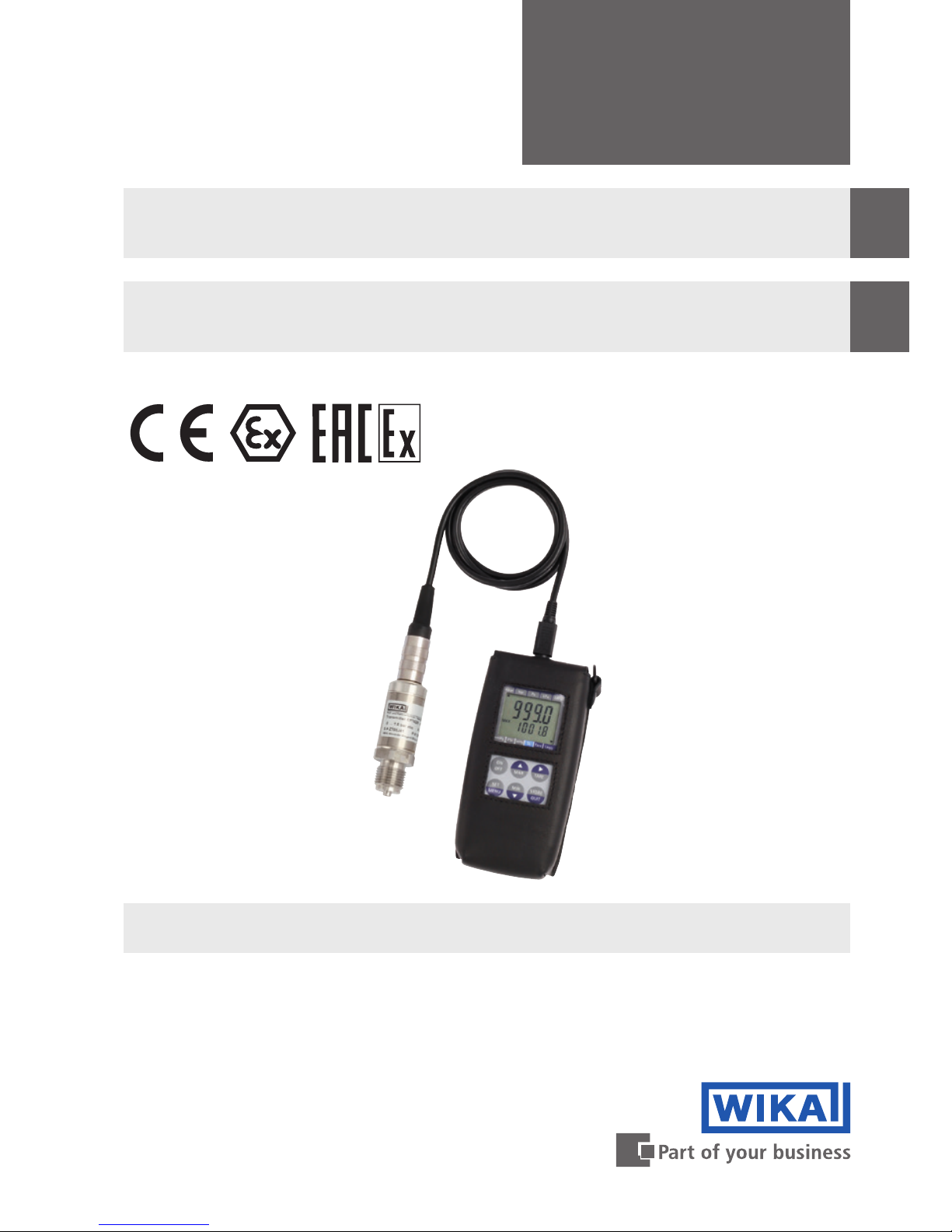
Intrinsically safe hand-held pressure indicator,
model CPH62I0-S1 and CPH62I0-S2
Eigensicheres Hand-Held Druckmessgerät,
Typ CPH62I0 und CPH62I0-S2
Intrinsically safe hand-held pressure indicator model CPH62I0-S1 with optional
model CPT62I0 reference pressure sensor
Page 2

2
11221801.04 10/2018 EN/DE
WIKA operating instructions, model CPH62I0
EN
DE
Operating instructions model CPH62I0-S1 and
CPH62I0-S2 Page 3 - 52
Betriebsanleitung Typ CPH62I0-S1 und
CPH62I0-S2 Seite 53 - 102
Further languages can be found at www.wika.com.
© 10/2018 WIKA Alexander Wiegand SE & Co. KG
All rights reserved. / Alle Rechte vorbehalten.
WIKA
®
is a registered trademark in various countries.
WIKA
®
ist eine geschützte Marke in verschiedenen Ländern.
Prior to starting any work, read the operating instructions!
Keep for later use!
Vor Beginn aller Arbeiten Betriebsanleitung lesen!
Zum späteren Gebrauch aufbewahren!
Page 3

3
WIKA operating instructions, model CPH62I0
EN
11221801.04 10/2018 EN/DE
Contents
1. General information 5
2. Short overview 6
2.1 Overview . . . . . . . . . . . . . . . . . . . . . . . . 6
2.2 Description . . . . . . . . . . . . . . . . . . . . . . . 6
2.3 Scope of delivery . . . . . . . . . . . . . . . . . . . . . 7
3. Safety 7
3.1 Explanation of symbols . . . . . . . . . . . . . . . . . . . 7
3.2 Intended use. . . . . . . . . . . . . . . . . . . . . . . 8
3.3 Improper use . . . . . . . . . . . . . . . . . . . . . . 8
3.4 Personnel qualification . . . . . . . . . . . . . . . . . . . 9
3.5 Labelling, safety marks . . . . . . . . . . . . . . . . . . . 9
3.5.1 Product label . . . . . . . . . . . . . . . . . . . . . . . . . . . . . . . . . . 9
3.5.2 Explanation of symbols. . . . . . . . . . . . . . . . . . . . . . . . . . . . .10
3.6 Ex marking . . . . . . . . . . . . . . . . . . . . . . . 10
3.6.1 Special conditions for use . . . . . . . . . . . . . . . . . . . . . . . . . . .11
3.6.2 Mains operation. . . . . . . . . . . . . . . . . . . . . . . . . . . . . . . . .12
3.6.3 Permitted batteries . . . . . . . . . . . . . . . . . . . . . . . . . . . . . . .13
4. Design and function 14
4.1 Display. . . . . . . . . . . . . . . . . . . . . . . . . 14
4.2 Function buttons and operation . . . . . . . . . . . . . . . .15
4.3 Electrical connections . . . . . . . . . . . . . . . . . . . 16
4.4 Voltage supply . . . . . . . . . . . . . . . . . . . . . . 17
4.5 Pressure sensors . . . . . . . . . . . . . . . . . . . . . 18
4.5.1 Available pressure sensors . . . . . . . . . . . . . . . . . . . . . . . . . .18
4.5.2 Connecting/changing pressure sensors . . . . . . . . . . . . . . . . . . .19
4.6 Serial or analogue interface. . . . . . . . . . . . . . . . . . 19
5. Transport, packaging and storage 21
5.1 Transport . . . . . . . . . . . . . . . . . . . . . . . .21
5.2 Packaging and storage . . . . . . . . . . . . . . . . . . . 21
6. Commissioning, operation 22
6.1 Commissioning . . . . . . . . . . . . . . . . . . . . . .22
6.2 Operation . . . . . . . . . . . . . . . . . . . . . . . . 22
6.3 Menu functions . . . . . . . . . . . . . . . . . . . . . .23
6.4 Configuring the instrument . . . . . . . . . . . . . . . . . .26
6.4.1 Pressure units (unit). . . . . . . . . . . . . . . . . . . . . . . . . . . . . .26
6.4.2 Sea-level (SL) and altitude (Alti) correction for absolute pressure sensor 26
6.4.3 Measurement types (rAtE). . . . . . . . . . . . . . . . . . . . . . . . . . .27
6.4.4 Averaging . . . . . . . . . . . . . . . . . . . . . . . . . . . . . . . . . . . .28
Contents
Page 4

4
WIKA operating instructions, model CPH62I0
EN
11221801.04 10/2018 EN/DE
Declarations of conformity can be found online at www.wika.com.
6.4.5 Zero point correction sensor 1 (OFS.1) or sensor 2 (OFS.2) . . . . . . . . .28
6.4.6 Scale correction sensor 1 (SCL.1) and sensor 2 (SCL.2) . . . . . . . . . . .28
6.4.7 Power-off function (P.oFF) . . . . . . . . . . . . . . . . . . . . . . . . . . .29
6.4.8 Instrument output (Ovt). . . . . . . . . . . . . . . . . . . . . . . . . . . . .29
6.4.9 Analogue output scaling with dAC.0 and dAC.1 (dAC.) . . . . . . . . . . . .29
6.4.10 Alarm (AL.). . . . . . . . . . . . . . . . . . . . . . . . . . . . . . . . . . . .30
6.4.11 Real-time clock (CLOC) . . . . . . . . . . . . . . . . . . . . . . . . . . . . .30
6.5 Operation of the logger function . . . . . . . . . . . . . . . . 31
6.5.1 Storing individual values (Func-Stor). . . . . . . . . . . . . . . . . . . . .32
6.5.2 Automatic recording with adjustable cycle time “Func-CYCL” . . . . . . . .33
7. Faults 36
8. Maintenance, cleaning and recalibration 39
8.1 Maintenance. . . . . . . . . . . . . . . . . . . . . . . 39
8.2 Battery replacement . . . . . . . . . . . . . . . . . . . .39
8.3 Cleaning . . . . . . . . . . . . . . . . . . . . . . . . 40
8.4 Recalibration. . . . . . . . . . . . . . . . . . . . . . . 40
9. Dismounting, return and disposal 41
9.1 Dismounting . . . . . . . . . . . . . . . . . . . . . . .41
9.2 Return . . . . . . . . . . . . . . . . . . . . . . . . .42
9.3 Disposal . . . . . . . . . . . . . . . . . . . . . . . . 42
10. Specifications 43
10.1 Complete measuring chain . . . . . . . . . . . . . . . . . 43
10.2 Digital indicator model CPH62I0 . . . . . . . . . . . . . . . 44
10.3 Reference pressure sensor model CPT62I0 . . . . . . . . . . .45
10.4 Safety-related characteristic values . . . . . . . . . . . . . . 46
10.5 Ex approvals . . . . . . . . . . . . . . . . . . . . . . 47
10.6 Certificates . . . . . . . . . . . . . . . . . . . . . . . 47
10.7 Dimensions in mm (in) . . . . . . . . . . . . . . . . . . .48
11. Accessories 50
Appendix 1: EU declaration of conformity model CPH62I0 51
Appendix 2: EU declaration of conformity model CPT62I0 52
Contents
Page 5

5
WIKA operating instructions, model CPH62I0
EN
11221801.04 10/2018 EN/DE
1. General information
1. General information
■
The models CPH62I0-S1 or CPH62I0-S2 intrinsically safe, hand-held pressure
indicators described in the operating instructions have been designed and
manufactured using state-of-the-art technology. All components are subject to
stringent quality and environmental criteria during production. Our management
systems are certified to ISO 9001 and ISO 14001.
■
These operating instructions contain important information on handling the instrument.
Working safely requires that all safety instructions and work instructions are observed.
■
Observe the relevant local accident prevention regulations and general safety
regulations for the instrument's range of use.
■
The operating instructions are part of the product and must be kept in the immediate
vicinity of the instrument and readily accessible to skilled personnel at any time. Pass
the operating instructions on to the next operator or owner of the instrument.
■
Skilled personnel must have carefully read and understood the operating instructions
prior to beginning any work.
■
The general terms and conditions contained in the sales documentation shall apply.
■
Subject to technical modifications.
■
Factory calibrations / DKD/DAkkS calibrations are carried out in accordance with
international standards.
■
Further information:
- Internet address: www.wika.de / www.wika.com
- Relevant data sheet:
CT 11.02
- Application consultant:
Tel.: +49 9372 132-0
Fax: +49 9372 132-406
info@wika.de
Page 6
6
WIKA operating instructions, model CPH62I0
EN
11221801.04 10/2018 EN/DE
2. Short overview
2. Short overview
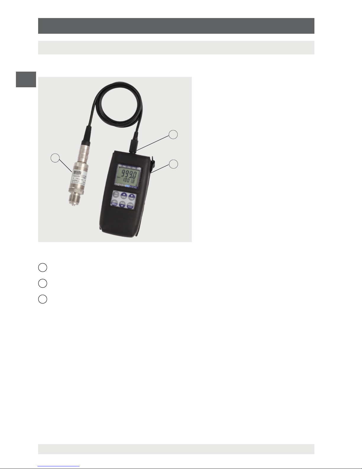
2.1 Overview
1
Sensor connection
2
Hand-held pressure indicator model CPH62I0-S1 or CPH62I0-S2 with leather case
(Ex protective cover)
3
Reference pressure sensor model CPT62I0
2.2 Description
The CPH62I0 hand-held pressure indicator can be used as a calibrator, and for any
application where an accurate pressure measurement is required, within hazardous
areas.
Model CPT62I0 reference pressure sensors with measuring ranges up to 1,000 bar
are available for the hand-held pressure indicator. This hand-held pressure indicator
automatically recognises the measuring range of the connected pressure sensor and
guarantees a high-accuracy pressure measurement.
In addition to pressure sensors for gauge and absolute pressure, differential pressure can
also be measured with the CPH62I0-S2 and two connected pressure sensors.
Selectable pressure units here are bar, mbar, psi, Pa, kPa, MPa, mmHg or inHg. An
integrated data logger and various other functions (such as Min, Max, Hold, Tare, zero
1
2
3
Page 7
7
WIKA operating instructions, model CPH62I0
EN
11221801.04 10/2018 EN/DE
2. Short overview / 3. Safety
point correction, alarm, power-off, variable measuring rate, sea level etc.) ensure that the
hand-held pressure indicator can be used for many different applications.
2.3 Scope of delivery
■
Hand-held pressure indicator, model CPH62I0-S1 or CPH62I0-S2, incl. 9 V battery
■
Leather case (Ex protective cover)
■
One sensor connection cable per channel, approx. 1.1 m (3.3 ft)
■
Calibration certificate for sensor
■
Choice of sensors
Cross-check scope of delivery with delivery note.
3. Safety
3.1 Explanation of symbols
WARNING!
... indicates a potentially dangerous situation that can result in serious injury
or death, if not avoided.
CAUTION!
... indicates a potentially dangerous situation that can result in light injuries or
damage to property or the environment, if not avoided.
DANGER!
... identifies hazards caused by electrical power. Should the safety
instructions not be observed, there is a risk of serious or fatal injury.
DANGER!
... indicates a potentially dangerous situation in the hazardous area that can
result in serious injury or death, if not avoided.
Information
... points out useful tips, recommendations and information for efficient and
trouble-free operation.
Page 8
8
WIKA operating instructions, model CPH62I0
EN
11221801.04 10/2018 EN/DE
3. Safety
3.2 Intended use
The CPH62I0 hand-held pressure indicator can be used as a calibrator, and for any
application where an accurate pressure measurement is required, within hazardous
areas.
To use the CPH62I0 in hazardous areas, it is imperative to insert the
hand-held pressure indicator into the leather case (Ex protective cover)
supplied. The press stud of the leather case (Ex protective cover) must be
closed.
The instrument has been designed and built solely for the intended use described here,
and may only be used accordingly.
The technical specifications contained in these operating instructions must be observed.
Improper handling or operation of the instrument outside of its technical specifications
requires the instrument to be taken out of service immediately and inspected by an
authorised WIKA service engineer.
Handle electronic precision measuring instruments with the required care (protect from
humidity, impacts, strong magnetic fields, static electricity and extreme temperatures,
do not insert any objects into the instrument or its openings). Plugs and sockets must be
protected from contamination.
The manufacturer shall not be liable for claims of any type based on operation contrary to
the intended use.
3.3 Improper use
WARNING!
Injuries through improper use
Improper use of the instrument can lead to hazardous situations and injuries.
▶
Refrain from unauthorised modifications to the instrument.
▶
Do not use the instrument with abrasive or viscous media.
▶
Only use the serial and analogue interfaces outside the hazardous areas.
▶
Only replace the batteries outside hazardous areas.
▶
Within hazardous areas, the accompanying leather case must be used!
Any use beyond or different to the intended use is considered as improper use.
Page 9
9
WIKA operating instructions, model CPH62I0
EN
11221801.04 10/2018 EN/DE
3. Safety
3.4 Personnel qualification
WARNING!
Risk of injury should qualification be insufficient
Improper handling can result in considerable injury and damage to
equipment.
▶
The activities described in these operating instructions may only be
carried out by skilled personnel who have the qualifications described
below.
Skilled personnel
Skilled personnel, authorised by the operator, are understood to be personnel who,
based on their technical training, knowledge of measurement and control technology and
on their experience and knowledge of country-specific regulations, current standards and
directives, are capable of carrying out the work described and independently recognising
potential hazards.
Special knowledge for working with instruments for hazardous areas:
The skilled personnel must have knowledge of ignition protection types, regulations and
provisions for equipment in hazardous areas.
Special operating conditions require further appropriate knowledge, e.g. of aggressive
media.
3.5 Labelling, safety marks
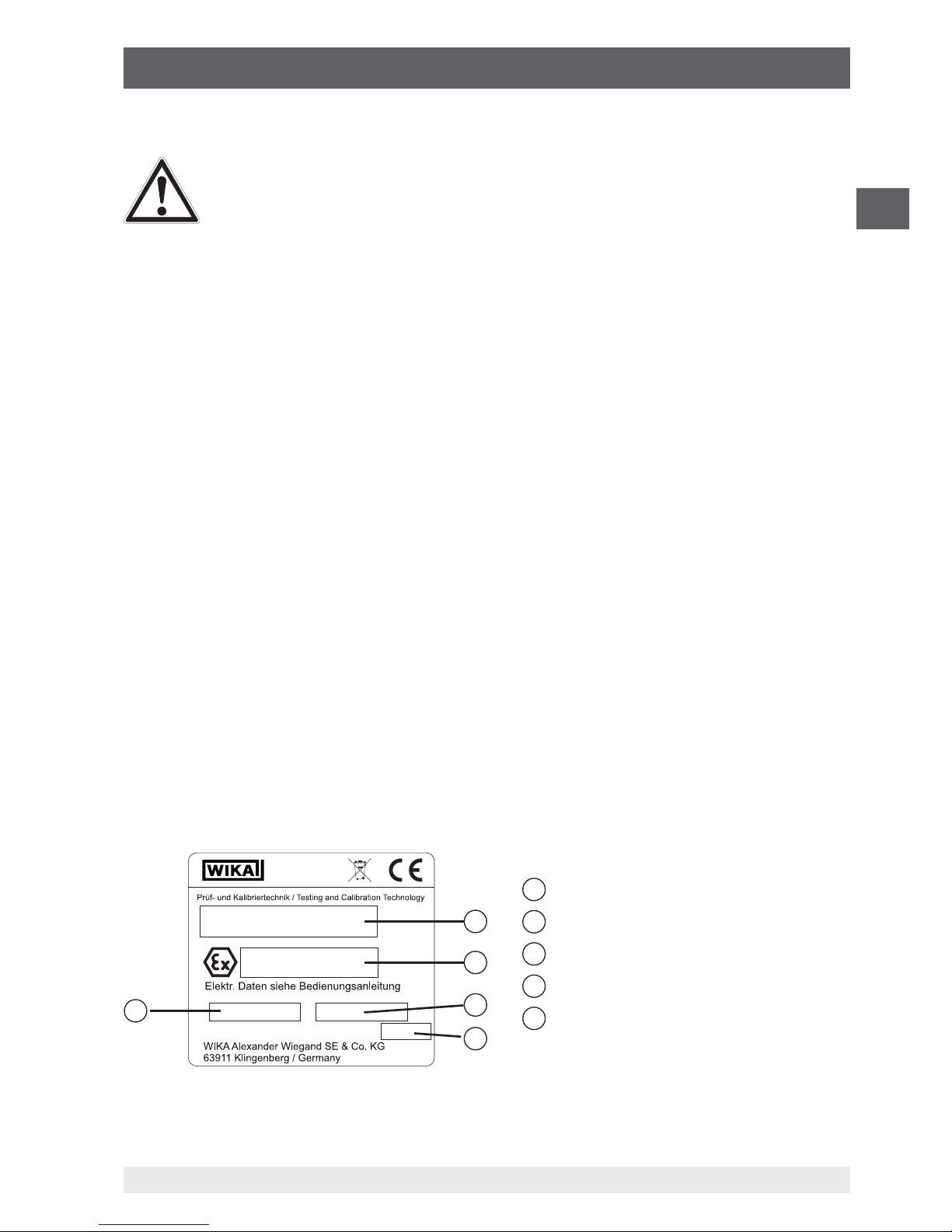
3.5.1 Product label
The operator is obliged to maintain the product label in a legible condition.
Product label for the hand-held pressure indicator
The product label is fixed on the rear of the hand-held.
1
2
3
4
5
1 Product name
2
Approval-related data
3
Article number
4
Date of manufacture
5
Serial number
Page 10
10
WIKA operating instructions, model CPH62I0
EN
11221801.04 10/2018 EN/DE
3. Safety
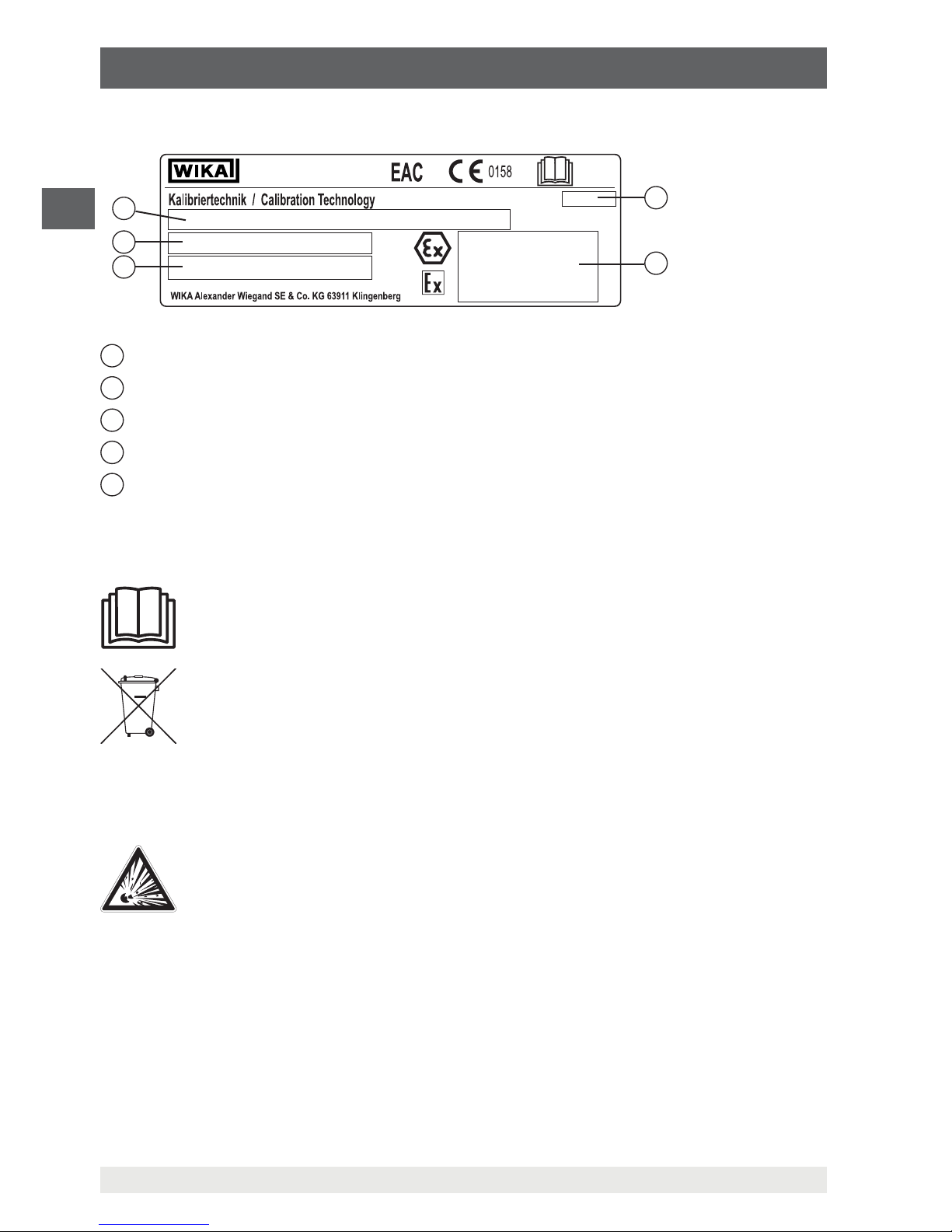
Product label for pressure sensor
1
Date of manufacture (month-year)
2
Approval-related data
3
Serial number and article number
4
Pressure measuring range and accuracy
5
Product name
3.5.2 Explanation of symbols
Before mounting and commissioning the hand-held pressure indicator,
ensure you read the operating instructions!
Do not dispose of with household waste. Ensure a proper disposal in
accordance with national regulations.
3.6 Ex marking
DANGER!
Danger to life due to loss of explosion protection
Non-observance of these instructions and their contents may result in the
loss of explosion protection.
▶
Observe the safety instructions in this chapter and further explosion
instructions in these operating instructions.
▶
Observe the information given in the applicable type examination
certificate and the relevant country-specific regulations for installation and
use in hazardous areas (e.g. IEC 60079-14, NEC, CEC).
▶
Operation of the serial and analogue interfaces is not permitted in
hazardous areas!
▶
Only use model CPT62I0 pressure sensors!
▶
Within hazardous areas, the accompanying leather case must be used!
5
3
4
2
1
Page 11
11
WIKA operating instructions, model CPH62I0
EN
11221801.04 10/2018 EN/DE
3. Safety
DANGER!
▶
Before reusing the hand-held pressure indicator as an intrinsically safe
instrument, prior to insertion into the leather case, make a general check
for external damage and functionality of the instrument and the leather
case!
▶
Ensure that the instrument is not exposed to environments that enable the
ingress of humidity, water, conducting liquids or dust.
▶
Only use the 9 V batteries listed, see chapter 3.6.3 “Permitted batteries”!
▶
Only replace the batteries outside the hazardous area, see chapter
8.2 “Battery replacement”!
▶
The permissible ambient temperature is -10 ... + 50 °C.
▶
The optionally available transport and storage case is not approved for
use within hazardous areas! This must always be stored outside the
hazardous area.
Check whether the classification is suitable for the application. Observe the relevant
national regulations.
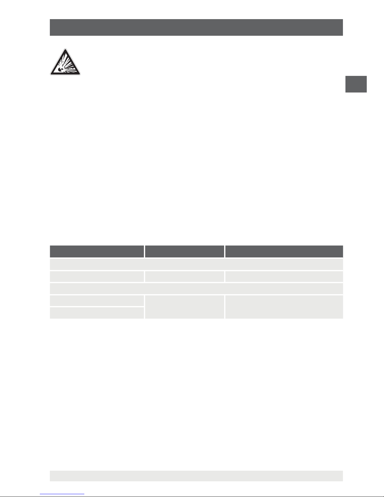
For applications that require category 2G instruments (potentially explosive gas
atmospheres), the following temperature class classification and ambient temperature
ranges apply:
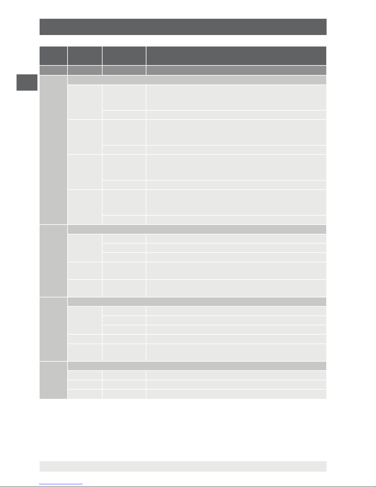
Marking Temperature class Ambient temperature range
Model CPH62I0-S1 or CPH62I0-S2 hand-held pressure indicator
II 2G Ex ib IIC T4 T1 ... T4 Ta = -10 ... +50 °C
Reference pressure sensor model CPT62I0
II 2G Ex ib IIC T4 T1 ... T4 Ta = -20 ... +50 °C
II 2G Ex ib IIC T4 Gb
3.6.1 Special conditions for use
Batteries
■
Only use the listed batteries, see chapter 3.6.3 “Permitted batteries”!
■
Only replace the batteries outside the hazardous area, see chapter 8.2 “Battery
replacement”!
Interface
■
Operation of the serial interface is not permitted in hazardous areas!
■
The connection and operation of the interfaces are only permitted outside hazardous
areas!
■
Only use the interface cables specified by WIKA!
Page 12

12
WIKA operating instructions, model CPH62I0
EN
11221801.04 10/2018 EN/DE
3. Safety
Pressure sensor
■
Only use model CPT62I0 pressure sensors! The use of other pressure sensors can
result in the destruction of the measuring instrument and of the pressure sensor.
■
When using two model CPT62I0 pressure sensors, make sure that these don't rest on
surfaces nor are screwed into items which are at a different potential!
■
For the electrical connection between the model CPT62I0 pressure sensor and the
CPH62I0-S1 or CPH62I0-S2 hand-held pressure indicator, use only the original WIKA
sensor connection cable intended for this. This also applies to the extension cable,
thus reaching a maximum permissible overall cable length of just under 5 m (16.4 ft).
Analogue output
■
The use of the analogue output is not permitted in hazardous areas!
■
Only connect passive voltmeters to the analogue output.
Equipotential bonding
■
All components (pressure sensor, power supply unit, interface, etc.) connected to the
instrument must be at the same potential or connected via equipotential bonding.
■
For use in potentially explosive atmospheres, only connect pressure sensors!
With two connected pressure sensors, take care that these are connected to the same
electrical potential, or an equipotential bonding exists.
Non-intrinsically safe use
The hand-held pressure indicator can also be used as a non-intrinsically safe instrument
for connection to non-intrinsically safe instruments (e.g. interface cables).
■
In this operating state also, only use approved accessories!
■
Before reusing the hand-held pressure indicator as an intrinsically safe instrument,
prior to insertion into the leather case, make a general check for external damage and
functionality of the instrument and the leather case!
Transport and storage cases
The optionally available transport and storage cases are not approved for use within
hazardous areas! The cases must always be stored outside the hazardous area.
3.6.2 Mains operation
DANGER!
Danger to life due to loss of explosion protection
Non-observance of these instructions and their contents may result in the
loss of explosion protection.
▶
Only use model GNG 10/3000 power supply units!
▶
The operation with an external power supply is not permitted in hazardous
areas!
Page 13
13
WIKA operating instructions, model CPH62I0
EN
11221801.04 10/2018 EN/DE
3. Safety
3.6.3 Permitted batteries
DANGER!
Danger to life due to loss of explosion protection
Non-observance of these instructions and their contents may result in the
loss of explosion protection.
▶
Only use the listed 9 V batteries!
▶
Only replace the batteries outside the hazardous area!
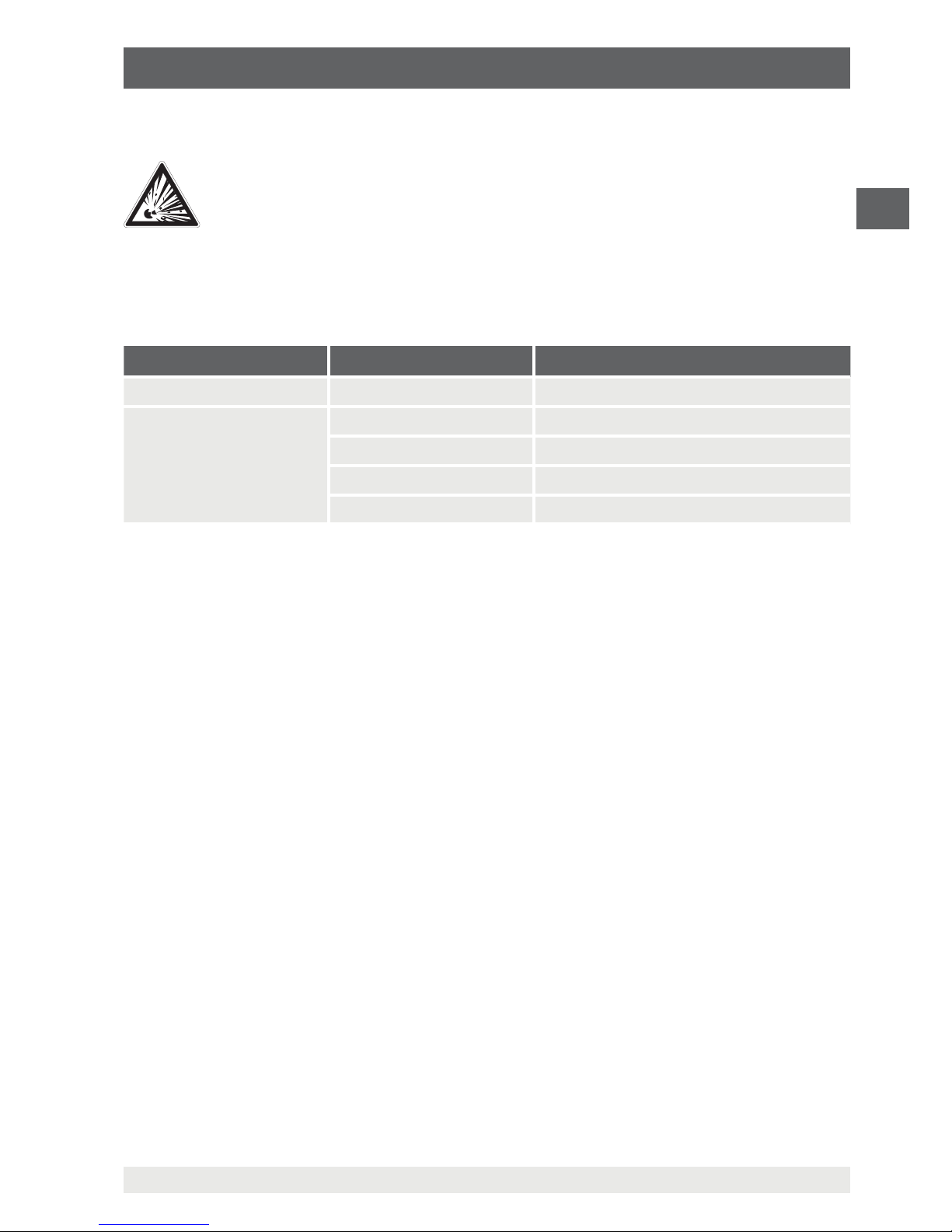
Approved batteries are:
Battery type Manufacturer Battery name
6F22 GB GREENCELL, 9 V (1604G)
6LF22
or
6LR61
GP SUPER alkaline, 9 V (1604A)
Duracell DURACELL PLUS, alkaline, 9 V
Varta Powerone alkaline, 9 V (No. 4122)
Varta INDUSTRIAL, alkaline, 9 V (No. 4022)
Page 14

14
WIKA operating instructions, model CPH62I0
EN
11221801.04 10/2018 EN/DE
4. Design and function
4. Design and function
4.1 Display
1
Main display: Current measured value for sensor 1
2
Secondary display: Current measured value for sensor 2 or differential value
between sensor 1 and sensor 2
3
Logg arrow: Logger is ready
Arrow blinking: Automatic recording (Logg CYCL) active
4
Tare arrow: Tare function is activated
5
SL arrow: Altitude correction (sea level) is activated
6
Display arrows for measured value units
7
Indication elements for showing the Min./Max. measured value, difference or hold
6
6
7
1
2
45 3
Page 15
15
WIKA operating instructions, model CPH62I0
EN
11221801.04 10/2018 EN/DE
4. Design and function
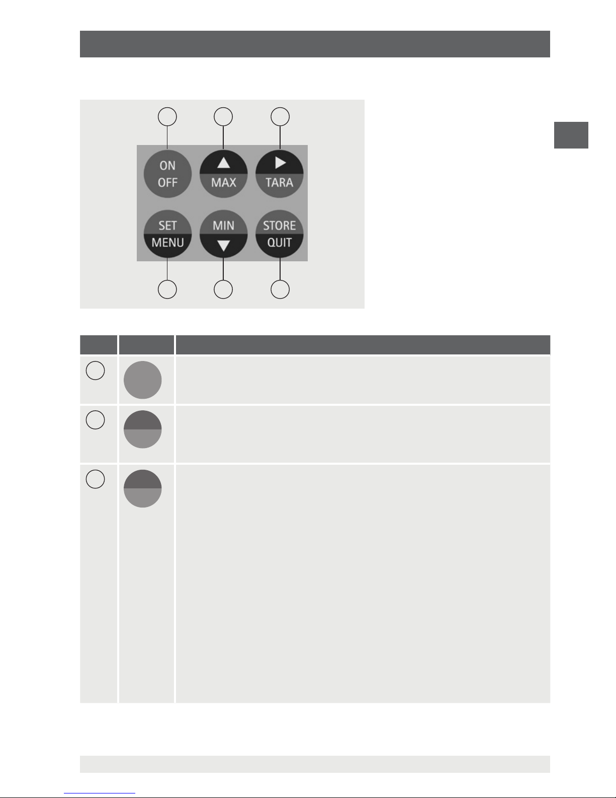
4.2 Function buttons and operation
Pos. Symbol Meaning
7
ON
OFF
On/Off button
Switching the CPH62I0-S1 or CPH62I0-S2 on and off
8
▲
MAX
Display of the respective max. memory value
By pressing the [MAX] button, the maximum value measured will be
displayed. Pressing it again hides it.
To clear the Max. memory, press the [MAX] button for > 2 seconds.
9
▲
TA R A
Activate the Tare function, zero point correction
■
Tare function
By pressing the [TARA] button, the display will be set to “0”. All
measurements from then on are displayed relative to the set tare value.
If the tare function is activated, the 'Tare' arrow will be displayed. To
deactivate, press and hold the [TARA] button for > 2 seconds.
⇒
By activating [TARA] the Min. and Max. memory will be deleted.
■
Zero point correction (for gauge pressure sensors)
When there is no pressure on the pressure ports, the instrument will display
a “0”. However, if there is a permanent deviation (when operating in troublefree ambient conditions), there is a possibility to carry out a permanent zero
point correction.
In order to carry out a zero point correction, press the [TARA] button for
approx. 5 seconds. (Only possible if the display value deviates from the
factory calibration by less than 2 %, e.g. 0 ... 25 bar (0 ... 360 psi)
⇒
Zero point correction up to 0.5 bar (7.3 psi) possible.
7
12
8
11
9
10
Page 16

16
WIKA operating instructions, model CPH62I0
EN
11221801.04 10/2018 EN/DE
4. Design and function
Pos. Symbol Meaning
⇒
The adjustment can only be carried out if the deviation is less than 500
digits. If a zero point correction has been made, this will be signalled
by the message 'nuLL-Corr' being displayed briefly as the instrument is
switched on.
■
Restoring the factory calibration
By pressing the [TARA] button for approx. 15 seconds, the factory settings
will be restored.
10
QUIT
STORE
Activate hold function or logger functions
(See chapter 6.5 “Operation of the logger function”)
■
Hold function
By pressing the [STORE/QUIT] button, the last measured value will be
shown in the lower display. Pressing it again hides the value again (only
when logger is deactivated).
■
Logger function
Activated by the [STORE/QUIT] button, only if the logger function has
been selected via the main menu (see chapter 6.5 “Operation of the logger
function”).
11
▲
MIN
Display the respective Min. memory
By pressing the [MIN] button, the minimum value measured will be displayed.
Pressing it again hides it.
To clear the Min. memory, press the [MIN] button for > 2 seconds.
12
MENU
SET
Enter configuration
By pressing the [SET/MENU] button for approx. 2 seconds, the settings
such as configuration, adjustment, alarm logger and system clock can be
accessed.
■
Differentiation
By pressing the [SET/MENU] button, the lower display will show the
difference of channel 1 to channel 2 (DIF = CH1 - CH2). Pressing it again
undoes this action. (Only with 2-channel version and 2 connected pressure
sensors).
Abbreviations, definitions
“XXX” Menu XXX will be selected
[XXX] Press button XXX
‚XXX‘ Display of a message 'XXX'
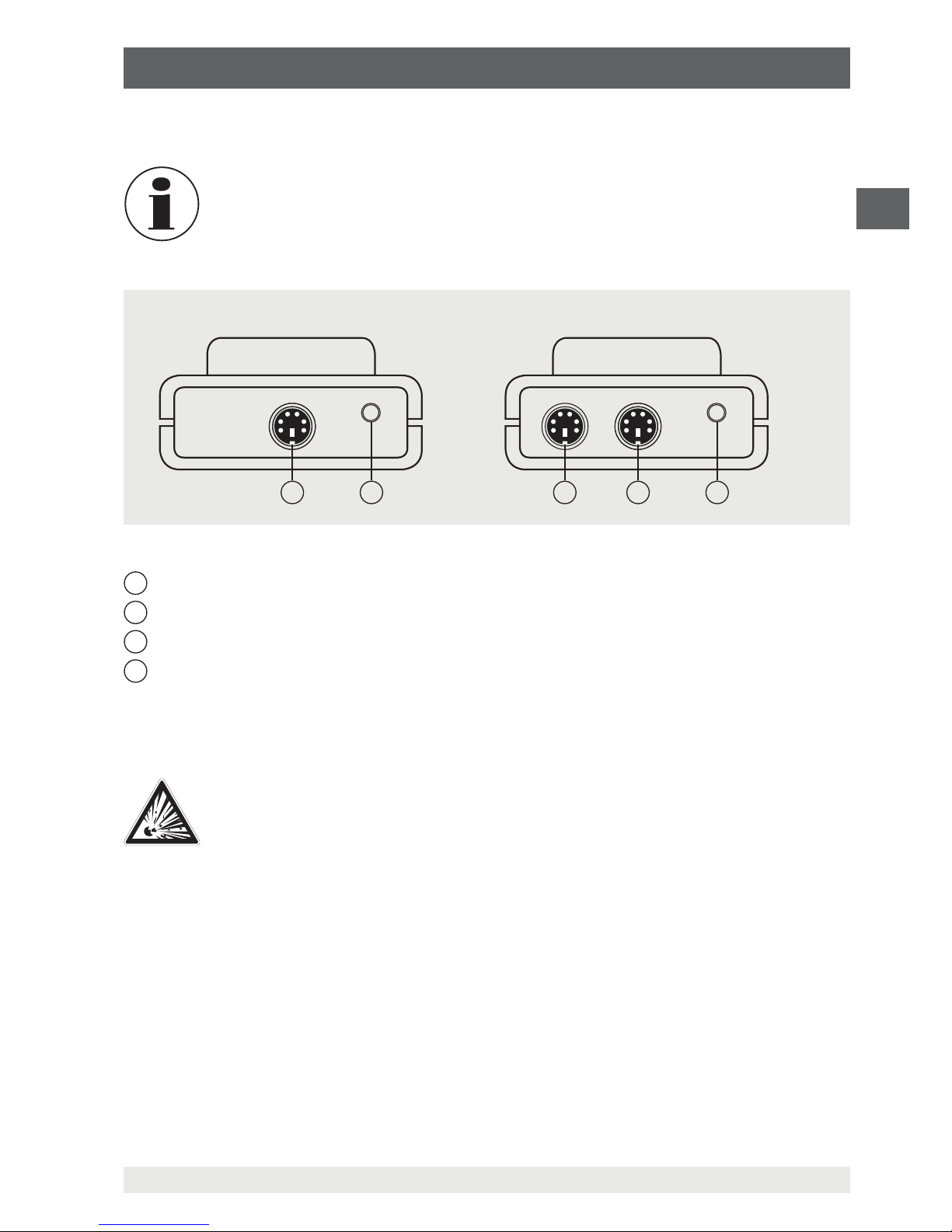
4.3 Electrical connections
On the upper edge of the instrument are located the connection sockets CH1 and CH2
(CH2 only with the 2-channel version) for the connection of model CPT62I0 pressure
sensors (see chapter 4.5 “Pressure sensors”), as is the socket for the connection of the
WIKA interface cable (see chapter 4.6 “Serial or analogue interface”).
Page 17
17
WIKA operating instructions, model CPH62I0
EN
11221801.04 10/2018 EN/DE
4. Design and function
The sockets for the connection of the interface can also be used for the function of
analogue output. For this, a corresponding analogue connection cable must be used.
The “interface” or “analogue output” operating mode must be congured via
menu and aects battery life!
1
Interface connector or optional analogue output
2
Connection channel 1 (only with CPH62I0-S1)
3
Connection channel 2 (only with CPH62I0-S2)
4
Connection channel 1 (only with CPH62I0-S2)
4.4 Voltage supply
DANGER!
Danger to life due to loss of explosion protection
Non-observance of these instructions and their contents may result in the
loss of explosion protection.
▶
Only use the listed batteries, see chapter 3.6.3 “Permitted batteries”!
▶
Only replace the batteries outside the hazardous area, see chapter
8.2 “Battery replacement”!
The voltage supply of the instrument is made via a 9 V battery. This is included in the
scope of delivery.
The battery life is approx. 300 hours of continuous operation with one sensor and a
measuring rate of 4/s.
1
2
1
34
Model CPH62I0-S1 Model CPH62I0-S2
Page 18

18
WIKA operating instructions, model CPH62I0
EN
11221801.04 10/2018 EN/DE
The battery indicator lights up
To avoid false readings, replace the batteries.
If “bAt” is displayed in the lower display, the battery has been run down and
must be replaced. However, the instrument function is still ensured for a
certain time.
If “bAt” is displayed in the upper display, the battery has been completely
run down.
If the instrument is not used for a long time, the battery should be removed.
The real-time clock has to be set again once the battery has been
reconnected.
The battery must only be used in a proper fashion and must be disposed
of properly in line with the current, national regulations. When storing the
instrument at over 50 °C (122 °F), the battery must be taken out.
4.5 Pressure sensors
DANGER!
Danger to life due to loss of explosion protection
Non-observance of these instructions and their contents may result in the
loss of explosion protection.
If third-party reference pressure sensors are used, they can damage the
hand-held pressure indicator and the reference pressure sensor.
▶
Only use model CPT62I0 reference pressure sensors!
▶
Only ever use the original connection cable from WIKA for the operation of
CPT62I0 reference pressure sensor.
4.5.1 Available pressure sensors
The hand-held has been designed so that all model CPT62I0 pressure sensors can
be connected without the need for any readjustment. A wide range of interchangeable
sensors is therefore available, with ranges of up to 1,000 bar (14,500 psi), see
10 “Specifications”.
4. Design and function
Page 19
19
WIKA operating instructions, model CPH62I0
EN
11221801.04 10/2018 EN/DE
4.5.2 Connecting/changing pressure sensors
CAUTION!
Damage to the instrument
For overpressure or gauge sensors, the pressure compensation vent hole is
found at the top of the sensor housing.
▶
This vent (with integrated diaphragm) must always remain clear!
Before switching the instrument on, connect the reference pressure sensor,
otherwise it may not be correctly identified by the instrument.
1. To connect or change the reference pressure sensor, switch off the instrument.
2. Connect the hand-held pressure indicator and the pressure sensor to each other
electrically using a separate sensor connection cable. Use the 7-pin plug contact on
the pressure sensor for this.
3. Connect the 7-pin connector to the reference pressure sensor in accordance with the
orientation guide and secure it through the connection sleeve.
Turn the connection sleeve clockwise without much force.
4. Connect the 6-pin M-DIN connector to the hand-held on CH1 or CH2 in accordance
with the orientation guide.
When connecting the sensor connection cable to the hand-held, the pressure sensor's
connector might not locate properly in the socket. In this case you should try holding the
connector by the bend protection, rather than by the connector sleeve.
▶
Connect the connector without tilt the threads.
⇒
If the connector is positioned correctly, it can be plugged in without any significant
effort.
▶
When removing the pressure sensor, do not pull on the sensor connection cable, but
only on the connector sleeve.
4.6 Serial or analogue interface
DANGER!
Danger to life due to loss of explosion protection
Non-observance of these instructions and their contents may result in the
loss of explosion protection.
Through working in flammable atmospheres, there is a risk of explosion
which can cause death.
▶
Operation of the serial or analogue interface is not permitted in hazardous
areas!
4. Design and function
Page 20

20
WIKA operating instructions, model CPH62I0
EN
11221801.04 10/2018 EN/DE
For data transfer to a computer, a galvanically -isolated interface adapter is available. This
is suitable for connection to a USB interface (USB driver needed).
The USB interface cable consists of a USB connector (model A) at one end of the cable
and a 3.5 mm stereo jack connector at the other end of the cable.
The cable is approx. 2 m (6.6 ft) long.
The CPH62I0-S1 or CPH62I0-S2 intrinsically safe version is in a protective
leather case (Ex protective cover). The interface connector is located under
the Ex protective cover.
4. Design and function
Page 21
21
WIKA operating instructions, model CPH62I0
EN
11221801.04 10/2018 EN/DE
5. Transport, packaging and storage
5. Transport, packaging and storage
5.1 Transport
Check the hand-held pressure indicator and the reference pressure sensor for any
damage that may have been caused by transport.
Obvious damage must be reported immediately.
CAUTION!
Damage through improper transport
With improper transport, a high level of damage to property can occur.
▶
When unloading packed goods upon delivery as well as during internal
transport, proceed carefully and observe the symbols on the packaging.
▶
With internal transport, observe the instructions in chapter 5.2 “Packaging
and storage”.
If the instrument is transported from a cold into a warm environment, the formation of
condensation may result in instrument malfunction. Before putting it back into operation,
wait for the instrument temperature and the room temperature to equalise.
5.2 Packaging and storage
Do not remove packaging until just before mounting.
Keep the packaging as it will provide optimum protection during transport (e.g. change in
use, sending for repair).
Permissible conditions at the place of storage:
■
Storage temperature: -20 ... +70 °C (-4 ... +158 °F)
■
Humidity: 0 ... 95 % relative humidity (non-condensing)
Avoid exposure to the following factors:
■
Direct sunlight or proximity to hot objects
■
Mechanical vibration, mechanical shock (putting it down hard)
■
Soot, vapour, dust and corrosive gases
Store the instrument in its original packaging in a location that fulfils the conditions
listed above. If the original packaging is not available, pack and store the instrument as
described below:
1. Wrap the instrument in an antistatic plastic film.
2. Place the instrument, along with the shock-absorbent material, in the packaging.
3. If stored for a prolonged period of time (more than 30 days), place a bag containing a
desiccant inside the packaging.
Page 22
22
WIKA operating instructions, model CPH62I0
EN
11221801.04 10/2018 EN/DE
6. Commissioning, operation
6. Commissioning, operation
Personnel: Skilled personnel
DANGER!
Danger to life from explosion!
Through working in flammable atmospheres, there is a risk of explosion
which can cause death.
▶
Only carry out set-up work in non-hazardous environments!
WARNING!
Physical injuries and damage to property and the environment caused
by hazardous media
Upon contact with hazardous media (e.g. oxygen, acetylene, flammable
or toxic substances), harmful media (e.g. corrosive, toxic, carcinogenic,
radioactive), and also with refrigeration plants and compressors, there is a
danger of physical injuries and damage to property and the environment.
Should a failure occur, aggressive media with extremely high temperature
and under high pressure or vacuum may be present at the instrument.
▶
For these media, in addition to all standard regulations, the appropriate
existing codes or regulations must also be followed.
6.1 Commissioning
Before switching the instrument on, connect the reference pressure sensor,
otherwise it may not be correctly identified by the instrument, see chapter
4.5.2 “Connecting/changing pressure sensors”.
Before switching on connect the reference pressure sensor(s) to the intended female
connector of the hand-held and make sure that a fully charged 9 V battery is inserted.
The connection sockets are marked on the instrument case with 1 or 2 correspondingly
(only with CPH62I0-S2). Next to these are located the serial or analogue interface.
6.2 Operation
On turning the instrument on, if the logger function is selected, the integrated clock‘s
time will be displayed briefly. If a zero point correction has been carried out, the display
will indicate this by showing “nuLL-Corr”.
Page 23

23
WIKA operating instructions, model CPH62I0
EN
11221801.04 10/2018 EN/DE
6. Commissioning, operation
After changing the battery the menu for setting the clock is displayed automatically
(‘CLOC’). Check the clock and adjust if necessary (see chapter 6.4.11 “Real-time clock
(CLOC)”).
6.3 Menu functions
Menu Parame-
ter
Values Meaning
[MENU]
▶ ▲ or ▼
SEt
ConF
Set Configuration: General settings
Unit
mbar, bar, ...
Display of unit
1) 2)
SL
oFF / on
Sea level: Switch sea-level correction on or off
1) 2)
ALti
-200 ... +9999
Altitude: Input of altitude above sea level [metre] (only if SL is
activated)
1) 2)
rAtE
Rate: Measuring rate (see chapter 6.4.3 “Measurement types (rAtE)”)
1)
SLo
Slow: Slow measurement (4 Hz filtered, low power
consumption)
1)
FASt
Fast: Fast measurement, filtered (> 1,000 Hz)
1)
P.dEt
Peak detection: fast measuring rate, unfiltered (> 1,000 Hz)
1)
t.AU6
1 ... 120
Time in seconds, calculated via the averaging function
3)
oFF
Averaging deactivated
3)
P.oFF
1 ... 120
Auto power-off delay in minutes.
If no button is pressed and there is no data transfer via the
interface, the instrument will switch itself off after this interval.
oFF
Auto power-off function deactivated (continuous operation)
Ovt
oFF
No output function, lowest power consumption
SEr
Instrument output is serial interface
dAC
Instrument output is analogue output 0 ... 1 V
Adr.
01, 11 ... 91
Communications address of the interface (only with Out =
SEr)
dAC.
CH1, CH2 or
CH DIF
Measuring input which should be used for the analogue
output (only with Out = dAC)
dAC.0
e.g. -5.00
...+5.00 mbar
Zero point setting for Out = dAC: Input of the measured value
at which the analogue output should output 0 V (only for Out
= dAC)
dAC.1
e.g. -5.00
...+5.00 mbar
Scale setting for Out = dAC: Input of the measured value
at which the analogue output should output 1 V (only for
Out = dAC)
1) If there is data in the logger memory, this menu item cannot be accessed. If these should be changed, the data must first be
deleted (see chapter 6.5 “Operation of the logger function”).
2) This menu can only be selected if an appropriate sensor is connected to connection 1. When using a second corresponding
sensor on connection 2 then the settings are adopted.
3) If the automatic recording is activated, this menu item cannot be accessed. If these should be changed, the cyclic data logger
must first be stopped (see chapter 6.5 “Operation of the logger function”).
Page 24
24
WIKA operating instructions, model CPH62I0
EN
11221801.04 10/2018 EN/DE
6. Commissioning, operation
Menu Parame-
ter
Values Meaning
[MENU]
▶ ▲ or ▼
SEt
CAL
Set Calibration: Adjustment of sensors
3)
OFS.1
Sensordep.,
e.g. -5.00 ...
+5.00 mbar
The zero point of sensor 1 will be displaced by this value
to compensate deviations of the probe or the measuring
instrument.
oFF
Zero point offset is deactivated (= 0.000)
SCL.1
e.g. -5.00
...+5.00 mbar
The measuring scale of sensor 1 will be changed by this
factor [%] to compensate deviations of the probe or the
measuring instrument.
oFF
Scale correction factor deactivated (= 0.000)
OFS.2
Sensordep.,
e.g. -5.00 ...
+5.00 mbar
The zero point of sensor 2 will be displaced by this value to
compensate for deviations of the probe or the measuring
instrument.
oFF
Zero point offset is deactivated (= 0.000)
SCL.2
e.g. -5.00
...+5.00 mbar
The measuring scale of sensor 2 will be changed by this
factor [%] to compensate deviations of the probe or the
measuring instrument.
oFF
Scale correction factor deactivated (= 0.000)
SEt
AL
.
Set Alarm: Alarm function configuration
4)
AL.
[1,2,DIF]
on
Alarm sensor is on; is indicated acoustically
no.So
Alarm sensor is on; is indicated acoustically
oFF
No alarm function
AL.Lo
[1,2,DIF]
Min-Range ...
... AL.Hi
Min. alarm limit (not when AL.oFF, Sensor min. is the lower
display range limit of the connected sensor)
AL.Hi
[1,2,DIF]
AL.Lo ...
... Max-Range
Max. alarm limit (not when AL.oFF, sensor max. is the upper
display range limit of the connected sensor)
SEt
Lo66
Set Logger: Logger function configuration
1)
Func
CYCL
Cyclic: Logger function “cyclic logger”
Stor
Store: Logger function “individual value logger”
oFF
No logger function
CYCL
1 ... 3600
Cycle time for cyclic logger [seconds]
Lo.Po
on / oFF
Low-power logger with very low current supply (only with
cyclic logger and slow measurement)
SEt
CLOC
Set Clock: Setting of real-time clock
CLOC
HH:MM
Setting the time hours:minutes
dAtE
TT.MM
Setting the time, day.month
YEAr
YYYY
Setting the year
1) If there is data in the logger memory, this menu item cannot be accessed. If these should be changed, the data must first be
deleted (see chapter 6.5 “Operation of the logger function”).
2) This menu can only be selected if an appropriate sensor is connected to connection 1. When using a second corresponding
sensor on connection 2 then the settings are adopted.
3) If the automatic recording is activated, this menu item cannot be accessed. If these should be changed, the cyclic data logger
must first be stopped (see chapter 6.5 “Operation of the logger function”).
4) If an alarm function limit is crossed (over or under), this is signalled by a “hooting” and a beeping.
Page 25

25
WIKA operating instructions, model CPH62I0
EN
11221801.04 10/2018 EN/DE
6. Commissioning, operation
MENU
SET
MENU
SET
MENU
SET
MENU
SET
MENU
SET
MENU
SET
MENU
SET
QUIT
STORE
QUIT
STORE
QUIT
STORE
QUIT
STORE
QUIT
STORE
QUIT
STORE
▲
TAR A
▲
TAR A
▲
TAR A
▲
TAR A
▲
TAR A
▲
TAR A
(Press for 2 seconds.)
Read
Lo66
Set
Conf
Set
CAL
Set
AL
Set
Lo66
Set
CLOC
(ring - shift)
Stored data
1)
Recall of the stored individual value logger data, see
chapter 6.5 “Operation of the logger function”
Configuration
Unit 2) / sea level 2) / measuring rate 2) / power-off /
interface address
Adjustment
3)
Of zero point and span
Alarm
3)
Min./Max. alarm visual
Logger
2)
Change over from hold on the logger function:
Individual value (SToR) or cyclic (CYCL)
System-clock
Time / day & month / year
1) Appears only if data has been stored in the individual value logger memory
2) Appears only if no data has been stored in the logger, see chapter 6.5 “Operation of the logger function”
3) If the automatic recording is activated, this menu item cannot be accessed. If these should be changed, the cyclic data logger
must first be stopped (see chapter 6.5 “Operation of the logger function”).
▲
MAX
▲
MIN
▲
TA RA
QUIT
STORE
Set parameter Next parameter Store or quit
Menu tree
Page 26

26
WIKA operating instructions, model CPH62I0
EN
11221801.04 10/2018 EN/DE
6. Commissioning, operation
6.4 Configuring the instrument
1. Press the [SET/MENU] button for 2 seconds.
⇒
The main menu “SEt” is accessed.
2. Keep pressing the [SET/MENU] button until the desired function is displayed.
3. With the [TARA] button, select the parameters.
4. With the [MIN] or [MAX] buttons, set the parameter.
5. With the [STORE/QUIT] button, confirm the entry.
6. Press the [SET/MENU] button.
⇒
Return to main menu.
6.4.1 Pressure units (unit)
Depending on the measuring range of the current pressure sensor, the pressure value
can be displayed in any one of the following units: mbar, bar, Pa, kPa, MPa, mmHg, inHg
or psi.
6.4.2 Sea-level (SL) and altitude (Alti) correction for absolute pressure sensor
With a connected absolute pressure sensor, the instrument measures absolute pressure.
This is not to be confused with the “air pressure at sea level” given by the weather station.
With this pressure indication, the altitude-dependent atmospheric pressure drop is
calculated. The instrument is capable of making this air pressure altitude correction.
Setting of “SL” and “Alti”
1. Press the [SET/MENU] button for 2 seconds.
⇒
The main menu “SEt” is accessed.
2. With the [TARA] button, select the “SL” parameters.
3. With the [MIN] or [MAX] buttons, activate the “SL” parameter.
4. With the [STORE/QUIT] button, confirm the entry.
5. With the [TARA] button, select the “Alti” parameters.
6. With the [MIN] or [MAX] buttons, enter the altitude.
7. With the [STORE/QUIT] button, confirm the entry.
8. Press the [SET/MENU] button.
⇒
Return to main menu.
The setting is only possible, if an absolute pressure sensor is connected to
sensor connection 1.
When the “Sea Level” function is activated, the arrow for 'SL' is indicated below in the
display. Once the altitude of the fixed location above sea level has been entered, the
instrument displays the absolute pressure at sea level.
Page 27

27
WIKA operating instructions, model CPH62I0
EN
11221801.04 10/2018 EN/DE
6. Commissioning, operation
When two absolute pressure sensors are connected, the “Sea Level” function
for both pressure sensors corresponds to the setting of pressure sensor 1.
6.4.3 Measurement types (rAtE)
The instrument supports three different measurement types for various purposes. Two of
these operate with an increased measuring rate of > 1,000 measurements/s.
6.4.3.1 Standard measurement (rAtE-SLo)
The measuring rate is 4 Hz. The averaging and filter functions are active.
Application range
■
Measurement of slowly changing or static pressures, e.g. calibration, leak testing,
atmospheric pressure measurement,
■
Highest measurement accuracy, insensitive to disturbances, low power consumption.
6.4.3.2 Peak value detection (rAtE-P.dEt)
The measuring rate is > 1,000 Hz and the measuring signal is displayed unfiltered.
Field of application in combination with logger function
■
Measurement of pressure spikes or fluctuating pressures with a resolution of < 1 ms.
■
The cyclic logger function records the arithmetic mean value, the highest and the
lowest pressure during the chosen time interval.
In this setting, there is an increased power consumption and the
measurement is susceptible to interference (also electromagnetic
interference).
6.4.3.3 Fast measurement = Fast (rAtE-FASt)
The measuring rate is > 1,000 Hz and the measuring signal is displayed filtered. As a
result, it is less sensitive to interference and the short-term spikes are filtered out. Other
than that, this function is identical to “rAtE-P.dEt”.
Page 28

28
WIKA operating instructions, model CPH62I0
EN
11221801.04 10/2018 EN/DE
6. Commissioning, operation
6.4.4 Averaging
The averaging function acts on the displayed values (display and interface). It is
completely independent of the averaging within the logger function (do not confuse
them!).
The averaging integrates the measured values during a chosen time interval and then
calculates the average display value.
The function is independent of the selected measuring rate (fast/slow measurement).
So long as a sufficiently long set time (in seconds) has not yet been measured in
order to calculate the mean value, “----” is shown in the display - in the lower display, a
'countdown' is displayed.
During the low-power logger operation, the averaging function is always deactivated.
Function of Min./Max. value memory in conjunction with the averaging function:
■
If averaging is activated and slow measurement, “rAtE-SLo”, is selected, the Min./
Max. memory value relates to the average display values.
■
If averaging is activated and fast measuring function is selected (“rAtE-FASt” or
“rAtE-P.dEt”), the Min./Max. memory value relates to the internal measured values (>
1,000 Hz measuring rate).
6.4.5 Zero point correction sensor 1 (OFS.1) or sensor 2 (OFS.2)
A zero point offset can be carried out for the respective measurement:
Displayed value = measured value – offset
Default setting
'off' = 0.0, i.e. no correction is made. The zero point correction, together with the slope
correction, is mainly used for the adjustment of sensor deviations. The entry is made in
the display unit.
6.4.6 Scale correction sensor 1 (SCL.1) and sensor 2 (SCL.2)
The scale of the corresponding measurement can be influenced by this factor (factor is in
%):
Displayed value = (measured value – offset) * (1+Scal/100)
Default setting
'off' = 0.000, i.e. no correction is made. The scale correction, together with the zero point
correction, is mainly used for the adjustment of sensor deviations.
Page 29
29
WIKA operating instructions, model CPH62I0
EN
11221801.04 10/2018 EN/DE
6. Commissioning, operation
6.4.7 Power-off function (P.oFF)
If no button is pressed and no serial communication occurs during the switch-off delay,
the instrument will automatically switch itself off. The switch-off delay can be set between
1 and 120 min. If “P.oFF” = “oFF” then the power-off function is deactivated.
6.4.8 Instrument output (Ovt)
DANGER!
Danger to life due to loss of explosion protection
Non-observance of these instructions and their contents may result in the
loss of explosion protection. Through working in flammable atmospheres,
there is a risk of explosion which can cause death.
▶
Operation of the serial or analogue interface is not permitted in hazardous
areas!
The output can be used as a USB or RS-232 interface or as an analogue output (0 ... 1 V).
6.4.9 Analogue output scaling with dAC.0 and dAC.1 (dAC.)
DANGER
Danger to life due to loss of explosion protection
Non-observance of these instructions and their contents may result in the
loss of explosion protection. Through working in flammable atmospheres,
there is a risk of explosion which can cause death.
▶
The use of the analogue output is not permitted in hazardous areas!
WARNING!
Damage to property through incorrect measuring instruments
By using incorrect measuring instruments, this damage could occur to the
hand-held.
▶
Only connect passive voltmeters to the analogue output.
Analogue output cannot be used during logger recordings.
With dAC.0 and dAC.1 the analogue output can be easily scaled.
▶
It must be ensured that the analogue output is not loaded too heavily, otherwise the
output value can be corrupted and the power consumption of the instrument increases
correspondingly.
Page 30
30
WIKA operating instructions, model CPH62I0
EN
11221801.04 10/2018 EN/DE
6. Commissioning, operation
Loads up to approx. 10 kΩ are harmless.
⇒
If the display exceeds the value set with dAC.1, then 1 V will be output.
⇒
If the display drops below the value set with dAC.0, then 0 V will be output.
⇒
In the event of an error (Err.1, Err.2, ----, etc.) an analogue signal slightly over 1 V will
be output.
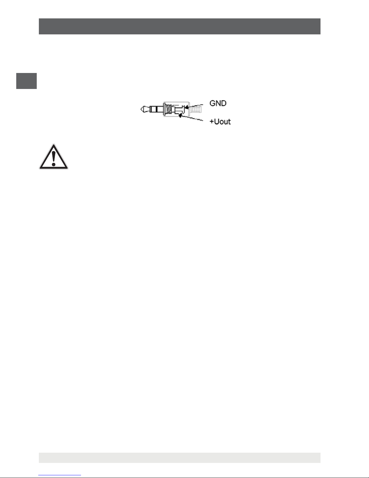
Jack connector wiring
WARNING!
Damage to property through incorrect jack connector
Using an incorrect jack connector or incorrect wiring can cause damage to
the hand-held.
▶
The 3rd connection must not be used.
▶
Only stereo jack connectors are permitted.
▶
Only use the original connection cable from WIKA.
6.4.10 Alarm (AL.)
There are 3 possible settings: off = “AL.oFF”, on = “AL.on”, or on = “AL.no.So”.
Under the following conditions, an alarm is given when the alarm function “AL.on” or “AL.
no.So” is active:
■
Value is below lower alarm limit “AL.Lo” or above upper alarm limit “AL.Hi”.
■
Sensor error (Sens-Erro)
■
Low battery, 'bAt'
■
Err.7: System error
In the event of an alarm, the display flashes, with interface access the 'PRIO' flag is set.
6.4.11 Real-time clock (CLOC)
The real-time clock is needed for the time allocation of the logger data. If required, check
the settings.
Checking the real-time clock
1. Press the [SET/MENU] button for 2 seconds.
⇒
The main menu “SEt” is accessed.
2. Keep pressing the [SET/MENU] button until “SEt-CLOC” is displayed.
3. With the [TARA] button, select the “CLOC” parameters.
4. With the [MIN] or [MAX] buttons, enter the time.
5. With the [TARA] button, select the “dAtE” parameters.
6. With the [MIN] or [MAX] buttons, enter the day and month.
7. With the [TARA] button, select the “YEAr” parameters.
Page 31

31
WIKA operating instructions, model CPH62I0
EN
11221801.04 10/2018 EN/DE
6. Commissioning, operation
8. With the [MIN] or [MAX] buttons, enter the year.
9. With the [STORE/QUIT] button, confirm the entry.
10. Press the [SET/MENU] button.
⇒
Return to main menu.
After changing the battery, the menu for setting the clock is automatically started after
switching on the instrument.
6.5 Operation of the logger function
Generally, the instrument supports two different logger functions which one activates via
the main menu. After activating the data logger in the main menu, the arrow is shown at
'Logg' in the main display. Subsequently, recording can be started as follows:
“Func-SToR”
▶
Press [STORE/QUIT] button.
⇒
A measuring result is recorded in each case.
“Func-CYCL”
▶
Press the [STORE/QUIT] button for 2 seconds.
⇒
'Lo66 rvn' shows in the display,
▶
Press [STORE/QUIT] button once more.
⇒
Recording is started.
⇒
The measuring results will automatically be recorded at the interval of the set
cycle time.
The logger records up to three measuring results:
■
Measured value or mean value (depending on selected function)
■
Min. value and max. value (Sensor 1, sensor 2, difference)
To evaluate the “Func-CYCL” data, WIKA’s GSoft (V 2.3 or higher) data logger evaluation
software must be used. The software also allows easy configuration and operation of the
logger.
When the logger function “Func-Stor” or “Func-CYCL” is activated (see menu navigation
for the main menu), the hold function is not available.
Min. and Max. value are, respectively, the minimum and the maximum measured value
during the last save operation. Therefore both the current pressure value and also any
pressure fluctuations can be accurately analysed.
Page 32

32
WIKA operating instructions, model CPH62I0
EN
11221801.04 10/2018 EN/DE
6. Commissioning, operation
6.5.1 Storing individual values (Func-Stor)
Each time the [STORE/QUIT] button is pressed, a measuring result will be recorded. The
data recorded can be viewed either on the display (an additional menu item “REAd-Lo66“
is displayed when accessing the configuration menu) or through the serial interface in a
PC (GSoft).
Storable data sets: 99
A data set consists of (max.):
■
Sensor 1: Current measured value at that data point
■
Sensor 1: Min. peak, Max. peak since last data point
■
Sensor 2 1): current measured value at that data point
■
Sensor 2 1): Min. peak, Max. peak since last data point
■
Difference sensor 1 - sensor 2 1): Measured value at that data point
■
Difference sensor 1 - sensor 2 1): Min. peak, Max. peak since last data point
■
Time and date stamp at that data point
1) Only valid for 2-channel version, CPH62I0-S2
With each recording, “St.XX” will be displayed briefly. XX represents the number of the
measuring result.
Delete stored data
1. Press the [STORE/QUIT] button for 2 seconds.
⇒
The main menu “CLr.” is accessed.
2. With the [MIN] or [MAX] button, select the desired function.
The following functions can be selected:
Delete all data sets Do not delete (cancel the
process)
Clear the last data set
3. With the [STORE/QUIT] button, confirm the selection.
4. Press the [SET/MENU] button.
⇒
Return to main menu.
Page 33

33
WIKA operating instructions, model CPH62I0
EN
11221801.04 10/2018 EN/DE
6. Commissioning, operation
Logger memory is full
If the logger memory is full, the display will show:
Reviewing individual values
In contrast to the cyclic logger function, individual values can also be viewed directly in
the display:
1. Press the [SET/MENU] button for 2 seconds.
⇒
Menu item “rEAd-Lo66” will be accessed.
2. With the [TARA] button, the last measuring result is displayed.
3. Press the [TARA] button again.
⇒
Individual values of the measuring result are displayed.
4. With the [MIN] or [MAX] buttons, recall some further measuring results.
5. Press the [TARA] button.
⇒
Individual values of the new measuring result are displayed.
6. Press the [SET/MENU] button.
⇒
Return to main menu.
6.5.2 Automatic recording with adjustable cycle time “Func-CYCL”
The logger cycle time is adjustable (see configuration). As an example “CYCL” = 1:00 a
measuring result will be stored every minute.
Additionally, with the measurement type “rAtE SLo”, a current-saving function is
selectable, “Lo.Po”. If this is “on”, it operates so that, while the logger is recording,
a measurement only occurs at the respective logger time. This reduces the power
consumption considerably and is therefore mainly recommended for long-term
measurements (e.g. leak testing).
Recordable measuring results: CPH62I0-S1: 10,000
CPH62I0-S2: 4,000
(at max. 64 recording sequences)
Cycle time: 1 ... 3,600 s (= 1 h),
adjustable in the configuration
A measuring result contains:
■
Slow measurements “rAtE-SLo”:
- Sensor 1: Current measured value at that data point
- Sensor 1: Min. peak, Max. peak since last data point
- Sensor 2
1)
: current value at that data point
- Sensor 2
1)
: Min. peak, Max. peak since last data point
- Difference (sensor 1 - sensor 2)
1)
: current value at that data point
- Difference sensor 1 - sensor 2
1)
: Min. peak, Max. peak since last data point
Page 34

34
WIKA operating instructions, model CPH62I0
EN
11221801.04 10/2018 EN/DE
■
Fast measurements “rAtE-FASt” or “rAtE-P.dEt”:
- Sensor 1: Arithmetic mean value since last data point
- Sensor 1: Min. peak, Max. peak since last data point
- Sensor 2
1)
: Arithmetic mean value since last data point
- Sensor 2
1)
: Min. peak, Max. peak since last data point
- Difference sensor 1 - sensor 2
1)
: arithmetical mean value since last data point
- Difference sensor 1 - sensor 2
1)
: Min. peak, Max. peak since last data point
1) Only valid for 2-channel version, CPH62I0-S2
Starting logger recording
1. Press the [STORE/QUIT] button for 2 seconds.
⇒
The display shows “Lo66 rvn”:
2. Press [STORE/QUIT] button once more.
⇒
Recording starts.
⇒
With each recording, the display will shortly show “St.XXXX”. Here, XXXX is the
number of the data set 1 ... 4,000 or 1 ... 10,000.
⇒
If the logger memory is full, the display will show:
⇒
The recording will be stopped automatically.
With the low-power-logger function “Lo.Po = on”, the instrument switches
itself off as soon as the logger memory is full.
Stopping the logger recording:
1. Press the [STORE/QUIT] button briefly.
⇒
A confirmation prompt then appears:
2. With the [MIN] or [MAX] button, select the desired function.
6. Commissioning, operation
Page 35

35
WIKA operating instructions, model CPH62I0
EN
11221801.04 10/2018 EN/DE
6. Commissioning, operation
The following functions can be selected:
Stop data logging Do not stop data logging
3. With the [STORE/QUIT] button, confirm the selection.
4. Press the [SET/MENU] button.
⇒
Return to main menu.
If, during a cyclic data logging, the measuring instrument is switched off, you
will automatically be asked whether the data logging should be stopped. The
instrument can only be switched off after the recording has been stopped.
The auto power-off function is deactivated during recording!
Clearing logger recording
1. Press the [STORE/QUIT] button for 2 seconds.
⇒
The display shows “Lo66 rvn”:
2. With the [MIN] or [MAX] buttons, change over the display.
⇒
The display shows “Lo66 CLr”:
3. Press [STORE/QUIT] button.
⇒
The option to clear the logger memory will be displayed:
4. With the [MIN] or [MAX] button, select the desired function.
Page 36

36
WIKA operating instructions, model CPH62I0
EN
11221801.04 10/2018 EN/DE
The following functions can be selected:
Delete all data sets Do not delete (cancel the
process)
Clear the last data set
5. With the [STORE/QUIT] button, confirm the selection.
6. Press the [SET/MENU] button.
⇒
Return to main menu.
6. Commissioning, operation / 7. Faults
7. Faults
Personnel: Skilled personnel
Protective equipment: Protective gloves and safety goggles
Tools: Spanner or torque spanner
DANGER!
Danger to life from explosion
Through working in flammable atmospheres, there is a risk of explosion
which can cause death.
▶
Only rectify faults in non-flammable atmospheres!
CAUTION!
Physical injuries and damage to property and the environment
If faults cannot be eliminated by means of the listed measures, the instrument
must be taken out of operation immediately.
▶
Ensure that pressure or signal is no longer present and protect against
accidental commissioning.
▶
Contact the manufacturer.
▶
If a return is needed, please follow the instructions given in chapter
9.2 “Return”.
Page 37

37
WIKA operating instructions, model CPH62I0
EN
11221801.04 10/2018 EN/DE
7. Faults
WARNING!
Physical injuries and damage to property and the environment caused
by hazardous media
Upon contact with hazardous media (e.g. oxygen, acetylene, flammable
or toxic substances), harmful media (e.g. corrosive, toxic, carcinogenic,
radioactive), and also with refrigeration plants and compressors, there is a
danger of physical injuries and damage to property and the environment.
Should a failure occur, aggressive media with extremely high temperature
and under high pressure or vacuum may be present at the instrument.
▶
For these media, in addition to all standard regulations, the appropriate
existing codes or regulations must also be followed.
▶
Wear the requisite protective equipment.
For contact details see chapter 1 “General information” or the back page of
the operating instructions.
Display Cause Measures
Low battery voltage, functioning is
only guaranteed for a short period of
time
Insert new battery, see chapter
8.2 “Battery replacement”
Battery is empty Insert new battery, see chapter
8.2 “Battery replacement”
SEnS
Erro
or
Err.9
There is no sensor connected Switch instrument off and connect
sensor.
Connected sensor or instrument is
defective
If second sensor available, check if
instrument is OK. Return defective
instrument/sensor to manufacturer
for repair.
Reading is significantly above or
below the measuring range
Check: Is the pressure within the
permissible measuring range of the
sensor?
Increase or decrease the pressure
correspondingly.
Check the pressure measuring range
of the sensor and, if necessary,
replace with a suitable sensor.
- - - -
- - - -
Logger data is being read by the
serial interface
As soon as the data transfer is
complete, the instrument will return to
normal measuring mode, no remedy
necessary.
Page 38

38
WIKA operating instructions, model CPH62I0
EN
11221801.04 10/2018 EN/DE
7. Faults
Display Cause Measures
No display or
undefinable
characters,
instrument is not
responding to
button press
Battery is empty. Insert new battery, see chapter
.8.2 “Battery replacement”
System error Disconnect battery, wait a short while,
reconnect
Instrument defect Send in for repair.
Err.1
Measured value above allowable
range
Check: Is the pressure over the
permissible measuring range of the
sensor?
⇒
Measured value too high!
⇒
Reduce pressure
Check the pressure measuring range
of the sensor and, if necessary,
replace with a suitable sensor with a
higher measuring range.
Sensor defect Send in for repair.
Err.2
Measured value below allowable
range.
Check: Is the pressure under the
permissible measuring range of the
sensor?
⇒
Measured value too low!
⇒
Reduce pressure
Check the pressure measuring range
of the sensor and, if necessary,
replace with a suitable sensor with a
lower measuring range.
Sensor defect Send in for repair
Err.3
Scale range exceeded. Check: Is the value over 9999
⇒
Value is too high!
⇒
Reduce value
Err.4
Under the scale range. Check: Is the value below -2000
(Tare?)
⇒
Value is too low!
⇒
Increase the value
Err.7
System error Send in for repair.
Err.11
Measured value could not be
calculated.
Select different unit.
Overrun has occurred. Select different unit.
Page 39

39
WIKA operating instructions, model CPH62I0
EN
11221801.04 10/2018 EN/DE
8. Maintenance, cleaning and recalibration
8. Maintenance, cleaning and recalibration
Personnel: Skilled personnel
Protective equipment: Protective gloves and safety goggles
Tools: Spanner or torque spanner
For contact details see chapter 1 “General information” or the back page of
the operating instructions.
8.1 Maintenance
The model CPH62I0 hand-held pressure indicator is maintenance-free.
Repairs must only be carried out by the manufacturer.
This does not apply to the battery replacement.
8.2 Battery replacement
DANGER!
Danger to life from explosion
Through working in flammable atmospheres, there is a risk of explosion
which can cause death.
▶
Only use the listed batteries, see chapter 3.6.3 “Permitted batteries”!
▶
Do not use rechargeable batteries!
▶
The instruments must not be opened in hazardous areas!
▶
Only replace the batteries outside the hazardous area!
▶
The battery cover must be closed and locked in place!
▶
Ensure the correct polarity.
The cover of the battery compartment is located on the underside of the hand-held.
Procedure
1. Switch off the instrument and remove it from the leather case (Ex protective cover).
Slide the lid of the battery compartment, on the back of the instrument, downwards.
2. Remove the empty battery and pull off the connection cable.
3. Connect the connection cable to the new battery and then insert this back into the
battery compartment.
⇒
Make sure that the connection cable is connected with the correct polarity.
⇒
Only use approved batteries, see chapter 3.6.3 “Permitted batteries”.
4. Slide the battery cover back on.
⇒
When closing the battery compartment make sure that the battery connection wires
are not jammed or damaged.
5. Insert the instrument back into the leather case (Ex protective cover).
Page 40

40
WIKA operating instructions, model CPH62I0
EN
11221801.04 10/2018 EN/DE
8. Maintenance, cleaning and recalibration
If the instrument is not used for a long time, remove the battery.
8.3 Cleaning
CAUTION!
Physical injuries and damage to property and the environment
Improper cleaning may lead to physical injuries and damage to property and
the environment. Residual media at the dismounted instrument can result in a
risk to persons, the environment and equipment.
▶
Wear the requisite protective equipment.
▶
Carry out the cleaning process as described below.
1. Prior to cleaning, isolate the instrument properly from the pressure source and switch
it off.
2. Clean the instrument with a moist cloth. Electrical connections must not come into
contact with moisture!
CAUTION!
Damage to property
Improper cleaning may lead to damage to the instrument!
▶
Do not use any aggressive cleaning agents.
▶
Do not use any hard or pointed objects for cleaning.
3. Wash or clean the dismounted instrument, in order to protect persons and the
environment from exposure to residual media.
8.4 Recalibration
DKD/DAkkS certificate - official certificates:
We recommend that the instrument is regularly recalibrated by the manufacturer, with
time intervals of approx. 12 months. The basic settings will be corrected if necessary.
Page 41

41
WIKA operating instructions, model CPH62I0
EN
11221801.04 10/2018 EN/DE
9. Dismounting, return and disposal
Personnel: Skilled personnel
Protective equipment: Protective gloves and safety goggles
Tools: Spanner or torque spanner
WARNING!
Physical injuries and damage to property and the environment
through residual media
Residual media at the model CPH62I0 hand-held pressure indicator or model
CPT62I0 reference pressure sensor can result in a risk to personnel, the
environment and equipment.
▶
Observe the information in the material safety data sheet for the
corresponding medium.
▶
Wash or clean the instrument, in order to protect personnel and the
environment from exposure to residual media.
9.1 Dismounting
WARNING!
Physical injuries and damage to property and the environment caused
by hazardous media
Upon contact with hazardous media (e.g. oxygen, acetylene, flammable
or toxic substances), harmful media (e.g. corrosive, toxic, carcinogenic,
radioactive), and also with refrigeration plants and compressors, there is a
danger of physical injuries and damage to property and the environment.
▶
Before storage of the instrument (following use) wash or clean it, in order
to protect people and the environment from exposure to residual media.
▶
Observe the information in the material safety data sheet for the
corresponding medium.
WARNING!
Physical injury
When dismounting, there is a danger from aggressive media and high
pressures.
▶
Observe the information in the material safety data sheet for the
corresponding medium.
▶
Wear the requisite protective equipment (only with the dismounting of the
pressure sensor).
▶
Only carry out dismounting in the depressurised state.
9. Dismounting, return and disposal
Page 42

42
WIKA operating instructions, model CPH62I0
EN
11221801.04 10/2018 EN/DE
9.2 Return
Strictly observe the following when shipping the instrument:
All instruments delivered to WIKA must be free from any kind of hazardous substances
(acids, bases, solutions, etc.) and must therefore be cleaned before being returned.
WARNING!
Physical injuries and damage to property and the environment
through residual media
Residual media at the model CPH62I0 hand-held pressure indicator or model
CPT62I0 reference pressure sensor can result in a risk to personnel, the
environment and equipment.
▶
With hazardous substances, include the material safety data sheet for the
corresponding medium.
▶
Clean the instrument, see chapter 8.3 “Cleaning”.
When returning the instrument, use the original packaging or a suitable transport
packaging.
To avoid damage:
1. Wrap the instrument in an antistatic plastic film.
2. Place the instrument, along with the shock-absorbent material, in the packaging.
Place shock-absorbent material evenly on all sides of the transport packaging.
3. If possible, place a bag, containing a desiccant, inside the packaging.
4. Label the shipment as transport of a highly sensitive measuring instrument.
Information on returns can be found under the heading “Service” on our local
website.
9.3 Disposal
Incorrect disposal can put the environment at risk.
Dispose of instrument components and packaging materials in an environmentally
compatible way and in accordance with the country-specific waste disposal regulations.
Do not dispose of with household waste. Ensure a proper disposal
in accordance with national regulations.
9. Dismounting, return and disposal
Page 43

43
WIKA operating instructions, model CPH62I0
EN
11221801.04 10/2018 EN/DE
10. Specifications
10. Specifications
DANGER!
Danger to life due to loss of explosion protection
The non-observance of the instructions for use in hazardous areas can lead
to the loss of the explosion protection.
▶
Adhere to the following limit values and instructions.
10.1 Complete measuring chain
Model CPH62I0 hand-held pressure indicator (complete measuring chain)
Measuring inputs 1 input for CPH62I0-S1
2 inputs for CPH62I0-S2
Measuring range
Gauge pressure mbar -600 ... 0 -600 ... +600 -400 ... 0 -400 ... +400
-250 ... 0 -250 ... +250 -100 ... +100 0 ... 100
0 ... 160 0 ... 250 0 ... 400 0 ... 600
bar -1 ... 0 -1 ... 1.5 -1 ... 3 -1 ... 5
-1 ... 9 -1 ... 15 -1 ... 24 -1 ... 39
0 ... 1 0 ... 1.6 0 ... 2.5 0 ... 4
0 ... 6 0 ... 10 0 ... 16 0 ... 25
0 ... 40 0 ... 60 0 ... 70 0 ... 100
0 ... 160 0 ... 250 0 ... 400 0 ... 600
0 ... 1,000
psi -9 ... 0 -9 ... +9 -4...0 -4 ... +4
-1.5...+1.5 -1.5 ... 0 0 ... 1.5 0 ... 2.5
0 ... 4 0 ... 6 0 ... 10 0 ... 14.5
0 ... 25 0 ... 40 0 ... 60 0 ... 90
0 ... 145 0 ... 250 0 ... 360 0 ... 580
0 ... 870 0 ... 1,450 0 ... 2,320 0 ... 3,630
0 ... 5,800 0 ... 8,700 0 ... 14,500
Absolute pressure bar
abs.
0 ... 0.25 0 ... 0.4 0 ... 0.6 0 ... 1
0 ... 1.6 0 ... 2.5 0 ... 4 0 ... 6
0 ... 10 0 ... 16 0 ... 25 0.8 ... 1.2
psi
abs.
0 ... 4 0 ... 9 0... 14.5 0 ... 25
0 ... 60 0 ... 90 0 ... 145 0 ... 250
Overpressure safety 3 times; ≤ 25 bar
2 times; > 25 bar ... ≤ 600 bar
1.5 times; > 600 bar
3 times; ≤ 360 psi
2 times; > 360 psi ... ≤ 8,700 psi
1.5 times; > 8,700 psi
Resolution dependent on pressure range (max. 4 1/2-digit)
Page 44

44
WIKA operating instructions, model CPH62I0
EN
11221801.04 10/2018 EN/DE
10. Specifications
Model CPH62I0 hand-held pressure indicator (complete measuring chain)
Accuracy of the
measuring chain
1)
0.2 % FS; {optional: 0.1 % FS} at reference conditions
2)
Pressure types Gauge pressure, {Absolute pressure of 0 ... 25 bar abs. (0 ... 360 psi
abs.) and vacuum ranges of -1 ... +24 bar (-14.5 ... 550 psi)}
Differential pressure measurement only with CPH62I0-S2, and two
model CPT62I0 reference pressure sensors connected
Sensor compatibility Compatible with model CPT62I0 reference pressure sensors
10.2 Digital indicator model CPH62I0
Digital indicator model CPH62I0
Display
Display Large 4 1/2-digit LC display for indication of two pressure values
and additional information
Indication range -19999 ... 19999 digits, depending on sensor used
Pressure units bar, mbar, psi, Pa, kPa, MPa, mmHg and inHg (depending on the
measuring range, freely selectable)
Functions
Measuring rate 4/s (“slow”); 1,000/s (“fast”); > 1,000/s unfiltered (peak value
detection), selectable
Memory Min./Max., integrated data logger
Functions via button press Min./Max. memory, Hold, Tare, zero point correction, logger (start/
stop)
Menu functions Min./Max. alarm (acoustic/visual), sea level (barometric air
pressure), power-off function, measuring rate, mean value filter
Mean value filter 1 ... 120 seconds, adjustable
Data logger Individual value logger: Up to 99 recordings incl. time via button
press
Cyclic logger: Automatic recording of up to 10,000 values incl.
time
Cycle time: selectable from 1 ... 3,600 seconds
Real-time clock integrated clock with date
Voltage supply
Power supply 9 V battery
Battery life > 300 hours of operation (1 sensor with a measuring rate of 4/s)
Permissible ambient conditions
Operating temperature -10 ... +50 °C (14 ... 122 °F)
Storage temperature -20 ... +70 °C (-4 ... +158 °F)
Relative humidity 0 ... 95 % r. h. (non-condensing)
Page 45

45
WIKA operating instructions, model CPH62I0
EN
11221801.04 10/2018 EN/DE
10. Specifications
Digital indicator model CPH62I0
Communication
Interface
3)
RS-232 or USB via interface cable
Analogue output
3)
DC 0 ... 1 V; configurable (selectable via menu alternative to
interface)
Case
Material impact-resistant ABS plastic, membrane keyboard, transparent
screen, leather case
Electrical connection Sensor cable: Bayonet connector, 7-pin
Interface: Stereo jack connector, 3.5 mm
Dimensions See technical drawing
Weight approx. 160 g (0.35 lbs) (incl. battery)
10.3 Reference pressure sensor model CPT62I0
Reference pressure sensor model CPT62I0
Process connection
4)
G ½ B; {flush (G 1 for 0.1 ... 1.6 bar (1.5 ... 23.2 psi)) or various
connection adapters on request)
Material
Wetted parts Stainless steel or Elgiloy
®
, (> 25 bar (360 psi) additionally with
NBR sealing)
Flush diaphragm version: Stainless steel {Hastelloy C4}; O-ring:
NBR {FKM/FPM or EPDM}
Internal transmission
medium
Synthetic oil (only for measuring ranges to 16 bar (250 psi) or
flush diaphragm)
{Halocarbon oil for oxygen applications}; {Listed by FDA for food
industry}
Sensor data
Accuracy
1)
≤ 0.2 % of span (at reference conditions)
2)
Compensated range 0 ... 80 °C (0 ... 176 °F)
Mean temperature
coefficient
≤ 0.2 % of span/10 K (outside the reference conditions)
{} Items in curved brackets are optional extras for an additional price.
1) It is defined by the total measurement uncertainty, which is expressed with the coverage factor (k = 2) and includes the following
factors: The intrinsic performance of the instrument, the measurement uncertainty of the reference instrument, long-term
stability, influence of ambient conditions, drift and temperature effects over the compensated range during a periodic zero point
correction.
2) Reference conditions: 15 ... 25 °C (59 ... 77 °F)
3) The use of the interface and analogue output is only permitted outside the hazardous area.
4) As an oxygen version, a flush diaphragm model is not available. In an oxygen version, the model CPT62I0 is only available in
overpressure ranges ≥ 0.25 bar (≥ 0.4 psi), with medium temperatures between -10 … +50 °C (14 … 122 °F) and using stainless
steel or Elgiloy
®
wetted parts.
Page 46

46
WIKA operating instructions, model CPH62I0
EN
11221801.04 10/2018 EN/DE
10. Specifications
Reference pressure sensor model CPT62I0
Permissible ambient conditions
Medium temperature
4)
-20 ... +50 °C (-4 ... +122 °F)
Operating temperature -20 ... +50 °C (-4 ... +122 °F)
Storage temperature -40 ... +80 °C (-40 ... +176 °F)
Relative humidity 0 ... 95 % r. h. (non-condensing)
Case
Material Stainless steel
Connection to the CPH62I0 via 1.1 m (3.3 ft) sensor connection cable (plug-and-play);
Optional: Extension cable approx. 3.8 m (12.5 ft), overall cable
length approx. 5 m (16.4 ft)
Ingress protection IP65
IP67 when connected
Dimensions See technical drawing
Weight approx. 220 g (0.49 lbs)
4) As an oxygen version, a flush diaphragm model is not available. In an oxygen version, the model CPT62I0 is only available in
overpressure ranges ≥ 0.25 bar (≥ 0.4 psi), with medium temperatures between -10 … +50 °C (14 … 122 °F) and using stainless
steel or Elgiloy
®
wetted parts.
10.4 Safety-related characteristic values
Connection values CPH62I0-S1 or CPH62I0-S2
Max. voltage Uo = DC 10.38 V
Max. current I
o
= 93 mA
Max. power P
o
= 240 mW
Max. internal capacitance C
o
= 1,240 nF
Max. internal inductance L
o
negligible
Power supply circuit CPT62I0
Max. input voltage Ui = DC 10.4 V
Max. input current I
i
= 100 mA
Max. input power P
i
= 500 mW
Max. internal capacitance C
i
= 600 nF
Max. internal inductance L
i
negligible
Page 47

47
WIKA operating instructions, model CPH62I0
EN
11221801.04 10/2018 EN/DE
10. Specifications
10.5 Ex approvals
Logo Description Country
EU declaration of conformity for CPH62I0-S1 and
CPH62I0-S2
■
EMC directive
■
EN 61326 emission (group 1, class B) and immunity (portable
equipment)
■
RoHS directive
■
ATEX directive
Hazardous areas
Ex i Zone 1 gas II 2G Ex ib IIC T4
T4 at -10 … +50 °C
European Union
EU declaration of conformity for CPT62I0
■
EMC directive
■
EN 61326 emission (group 1, class B) and immunity (portable
equipment)
■
Pressure equipment directive
■
PS > 200 bar; module A, pressure accessory
■
RoHS directive
■
ATEX directive
Hazardous areas
Ex i Zone 1 gas II 2G Ex ib IIC T4
II 2G Ex ib IIC T4 Gb
Ta = -20 ... +50 °C
European Union
EAC
■
EMC directive
■
Pressure equipment directive
■
Hazardous areas (see approval)
Eurasian
Economic
Community
10.6 Certificates
Certificate
Calibration Standard: 3.1 calibration certificate per DIN EN 10204
Option: DKD/DAkkS calibration certificate
Recommended
recalibration interval
1 year (dependent on conditions of use)
Approvals and certificates, see website
For further specifications see WIKA data sheet CT 11.02 and the order documentation.
Page 48

48
WIKA operating instructions, model CPH62I0
EN
11221801.04 10/2018 EN/DE
10. Specifications
10.7 Dimensions in mm (in)
142 (5,59)
71 (2,80)
25 (0,98)
36 (1,42)
Digital indicator, CPH62I0-S1 or CPH62I0-S2
Page 49

49
WIKA operating instructions, model CPH62I0
EN
11221801.04 10/2018 EN/DE
27
Ø 27 (Ø 1.06)
88.5 (3.48)
28.5
+0.3
(1.12
+0.01
)
20 (0.79)
3 (0.12)
3 (0.12)
G 1/2 B
Ø 17.5
(Ø 0.69)
Ø 6 (Ø 0.24)
CPT62I0 reference pressure sensor
10. Specifications
Page 50

50
WIKA operating instructions, model CPH62I0
EN
11221801.04 10/2018 EN/DE
11. Accessories
11. Accessories
Description Order code
CPH-A-6I-
9 V battery -B-
Sealing set
Consisting of 4 x G ½ USIT seals, 2 x G ¼ USIT seals
and plastic box
-D-
Plastic case
for 1 x hand-held, 3 x pressure sensors, accessories
-K-
for 1 x hand-held, 5 x pressure sensors, 1 x pneumatic
hand test pump CPP30, accessories
-L-
Transport case from aluminium
for 1 x hand-held, 5 x pressure sensors, 1 x hydraulic
hand spindle pump CPP1000-L, accessories
-M-
Cable
Sensor connection cable, approx. 1.1 m (3.3 ft) (Ex
version)
-S-
Extension cable for connection of sensors, approx. 3.8 m
(12.5 ft) to approx. 5 m (16.4 ft) (Ex version)
-V-
Interface cable
for RS-232 interfaces
-R-
for USB interfaces -U-
Calibration software
GSoft data logger evaluation software
-G-
Ordering information for your enquiry:
1. Order code: CPH-A-6I
2. Option:
⇓
[ ]
WIKA accessories can be found online at www.wika.com.
Page 51

51
WIKA operating instructions, model CPH62I0
EN
11221801.04 10/2018 EN/DE
Appendix 1: EU declaration of conformity model CPH62I0
Page 52

52
WIKA operating instructions, model CPH62I0
EN
11221801.04 10/2018 EN/DE
Appendix 2: EU declaration of conformity model CPT62I0
Page 53

53
WIKA Betriebsanleitung, Typ CPH62I0
DE
11221801.04 10/2018 EN/DE
Inhalt
1. Allgemeines 55
2. Kurzübersicht 56
2.1 Überblick . . . . . . . . . . . . . . . . . . . . . . . .56
2.2 Beschreibung . . . . . . . . . . . . . . . . . . . . . . 56
2.3 Lieferumfang. . . . . . . . . . . . . . . . . . . . . . . 57
3. Sicherheit 57
3.1 Symbolerklärung . . . . . . . . . . . . . . . . . . . . . 57
3.2 Bestimmungsgemäße Verwendung . . . . . . . . . . . . . . .58
3.3 Fehlgebrauch . . . . . . . . . . . . . . . . . . . . . . 58
3.4 Personalqualifikation . . . . . . . . . . . . . . . . . . . .59
3.5 Beschilderung, Sicherheitskennzeichnungen. . . . . . . . . . . . 59
3.5.1 Typenschild . . . . . . . . . . . . . . . . . . . . . . . . . . . . . . . . . . .59
3.5.2 Symbolerklärung . . . . . . . . . . . . . . . . . . . . . . . . . . . . . . . .60
3.6 Ex-Kennzeichnung. . . . . . . . . . . . . . . . . . . . .60
3.6.1 Besondere Bedingungen für die Verwendung . . . . . . . . . . . . . . . .61
3.6.2 Netzgerätebetrieb . . . . . . . . . . . . . . . . . . . . . . . . . . . . . . .63
3.6.3 Zugelassene Batterien . . . . . . . . . . . . . . . . . . . . . . . . . . . . .63
4. Aufbau und Funktion 64
4.1 Anzeige . . . . . . . . . . . . . . . . . . . . . . . . 64
4.2 Funktionstasten und Bedienung . . . . . . . . . . . . . . . . 65
4.3 Elektrische Anschlüsse . . . . . . . . . . . . . . . . . . . 66
4.4 Spannungsversorgung . . . . . . . . . . . . . . . . . . . 67
4.5 Drucksensoren . . . . . . . . . . . . . . . . . . . . . .68
4.5.1 Verfügbare Drucksensoren . . . . . . . . . . . . . . . . . . . . . . . . . .68
4.5.2 Drucksensoren anschließen/wechseln . . . . . . . . . . . . . . . . . . . .69
4.6 Serielle oder analoge Schnittstelle . . . . . . . . . . . . . . . 69
5. Transport, Verpackung und Lagerung 71
5.1 Transport . . . . . . . . . . . . . . . . . . . . . . . .71
5.2 Verpackung und Lagerung . . . . . . . . . . . . . . . . . .71
6. Inbetriebnahme, Betrieb 72
6.1 Inbetriebnahme . . . . . . . . . . . . . . . . . . . . . . 72
6.2 Betrieb. . . . . . . . . . . . . . . . . . . . . . . . . 72
6.3 Menüfunktionen . . . . . . . . . . . . . . . . . . . . . 73
6.4 Konfigurieren des Gerätes . . . . . . . . . . . . . . . . . . 76
6.4.1 Druckeinheiten (Unit) . . . . . . . . . . . . . . . . . . . . . . . . . . . . .76
6.4.2 Höhenkorrektur bei Absolutdruck-Sensor (SL) und (Alti) . . . . . . . . .76
6.4.3 Messarten (rAtE) . . . . . . . . . . . . . . . . . . . . . . . . . . . . . . . .77
6.4.4 Mittelwertbildung . . . . . . . . . . . . . . . . . . . . . . . . . . . . . . . .78
Inhalt
Page 54

54
WIKA Betriebsanleitung, Typ CPH62I0
DE
11221801.04 10/2018 EN/DE
Konformitätserklärungen finden Sie online unter www.wika.de.
6.4.5 Nullpunktkorrektur Sensor 1 (OFS.1) bzw. Sensor 2 (OFS.2) . . . . . . . . .78
6.4.6 Steigungskorrektur Sensor 1 (SCL.1) bzw. Sensor 2 (SCL.2). . . . . . . . .78
6.4.7 Abschaltverzögerung (P.oFF) . . . . . . . . . . . . . . . . . . . . . . . . .79
6.4.8 Geräteausgang (Ovt). . . . . . . . . . . . . . . . . . . . . . . . . . . . . .79
6.4.9 Analogausgang-Skalierung mit dAC.0 und dAC.1 (dAC.) . . . . . . . . . . .79
6.4.10 Alarm (AL.). . . . . . . . . . . . . . . . . . . . . . . . . . . . . . . . . . . .80
6.4.11 Echtzeituhr (CLOC) . . . . . . . . . . . . . . . . . . . . . . . . . . . . . . .80
6.5 Bedienung der Loggerfunktion. . . . . . . . . . . . . . . . . 81
6.5.1 Einzelwerte speichern (Func-Stor) . . . . . . . . . . . . . . . . . . . . . .82
6.5.2 Automatische Aufzeichnung mit einstellbarer Zykluszeit „Func-CYCL“ . . .83
7. Störungen 86
8. Wartung, Reinigung und Rekalibrierung 89
8.1 Wartung . . . . . . . . . . . . . . . . . . . . . . . . 89
8.2 Batteriewechsel. . . . . . . . . . . . . . . . . . . . . . 89
8.3 Reinigung. . . . . . . . . . . . . . . . . . . . . . . . 90
8.4 Rekalibrierung . . . . . . . . . . . . . . . . . . . . . . 90
9. Demontage, Rücksendung und Entsorgung 91
9.1 Demontage . . . . . . . . . . . . . . . . . . . . . . . 91
9.2 Rücksendung . . . . . . . . . . . . . . . . . . . . . . 92
9.3 Entsorgung . . . . . . . . . . . . . . . . . . . . . . . 92
10. Technische Daten 93
10.1 Gesamte Messkette. . . . . . . . . . . . . . . . . . . . 93
10.2 Digitales Anzeigegerät Typ CPH62I0 . . . . . . . . . . . . . . 94
10.3 Referenz-Drucksensor Typ CPT62I0 . . . . . . . . . . . . . . 95
10.4 Sicherheitstechnische Kennwerte . . . . . . . . . . . . . . . 96
10.5 Ex-Zulassungen . . . . . . . . . . . . . . . . . . . . . 97
10.6 Zertifikate/Zeugnisse . . . . . . . . . . . . . . . . . . . 97
10.7 Abmessungen in mm (in) . . . . . . . . . . . . . . . . . .98
11. Zubehör 100
Anlage 1: EU-Konformitätserklärung Typ CPH62I0 101
Anlage 2: EU-Konformitätserklärung Typ CPT62I0 102
Inhalt
Page 55

55
WIKA Betriebsanleitung, Typ CPH62I0
DE
11221801.04 10/2018 EN/DE
1. Allgemeines
1. Allgemeines
■
Das in der Betriebsanleitung beschriebene eigensichere Hand-Held Druckmessgerät
Typ CPH62I0-S1 oder CPH62I0-S2 wird nach dem aktuellen Stand der Technik konstruiert und gefertigt. Alle Komponenten unterliegen während der Fertigung strengen
Qualitäts- und Umweltkriterien. Unsere Managementsysteme sind nach ISO 9001 und
ISO 14001 zertifiziert.
■
Diese Betriebsanleitung gibt wichtige Hinweise zum Umgang mit dem Gerät.
Voraussetzung für sicheres Arbeiten ist die Einhaltung aller angegebenen
Sicherheitshinweise und Handlungsanweisungen.
■
Die für den Einsatzbereich des Gerätes geltenden örtlichen
Unfallverhütungsvorschriften und allgemeinen Sicherheitsbestimmungen einhalten.
■
Die Betriebsanleitung ist Produktbestandteil und muss in unmittelbarer Nähe des
Gerätes für das Fachpersonal jederzeit zugänglich aufbewahrt werden. Betriebsanleitung an nachfolgende Benutzer oder Besitzer des Gerätes weitergeben.
■
Das Fachpersonal muss die Betriebsanleitung vor Beginn aller Arbeiten sorgfältig
durchgelesen und verstanden haben.
■
Es gelten die allgemeinen Geschäftsbedingungen in den Verkaufsunterlagen.
■
Technische Änderungen vorbehalten.
■
Werkskalibrierungen / DKD/DAkkS-Kalibrierungen erfolgen nach internationalen
Normen.
■
Weitere Informationen:
- Internet-Adresse: www.wika.de / www.wika.com
- Zugehöriges Datenblatt:
CT 11.02
- Anwendungsberater:
Tel.: +49 9372 132-0
Fax: +49 9372 132-406
info@wika.de
Page 56

56
WIKA Betriebsanleitung, Typ CPH62I0
DE
11221801.04 10/2018 EN/DE
2. Kurzübersicht
2. Kurzübersicht
2.1 Überblick
1
Sensoranschluss
2
Hand-Held Druckmessgerät Typ CPH62I0-S1 oder CPH62I0-S2 mit Ledertasche
(Ex-Schutzhülle)
3
Referenz-Drucksensor Typ CPT62I0
2.2 Beschreibung
Das Hand-Held Druckmessgerät CPH62I0 kann als Kalibriergerät sowie für jede Anwendung, bei der eine genaue Druckmessung erforderlich ist, im explosionsgefährdeten
Bereich verwendet werden.
Für das Hand-Held Druckmessgerät stehen Referenz-Drucksensoren Typ CPT62I0
mit Messbereichen bis zu 1.000 bar zur Verfügung. Dieses erkennt automatisch
den Messbereich des jeweils angesteckten Drucksensors und gewährleistet eine
hochgenaue Druckmessung.
Neben Drucksensorik für Relativ- und Absolutdruck lässt sich mit dem CPH62I0-S2 und
zwei angeschlossenen Drucksensoren auch Differenzdruck messen.
Wählbare Druckeinheiten sind hierbei bar, mbar, psi, Pa, kPa, MPa, mmHg oder inHg.
Ein integrierter Datenlogger und diverse Funktionen, wie z. B. Min, Max, Hold, Tara,
1
2
3
Page 57

57
WIKA Betriebsanleitung, Typ CPH62I0
DE
11221801.04 10/2018 EN/DE
2. Kurzübersicht / 3. Sicherheit
Nullpunktkorrektur, Alarm, Power-off, variable Messrate, Sea Level etc., ermöglichen den
vielfältigen Einsatz des Hand-Held Druckmessgerätes.
2.3 Lieferumfang
■
Hand-Held Druckmessgerät Typ CPH62I0-S1 oder CPH62I0-S2 inkl. 9-V-Blockbatterie
■
Ledertasche (Ex-Schutzhülle)
■
Ein Sensoranschlusskabel ca. 1,1 m (3,3 ft) pro Kanal
■
Kalibrierzertifikat für Sensorik
■
Sensorik nach Wahl
Lieferumfang mit dem Lieferschein abgleichen.
3. Sicherheit
3.1 Symbolerklärung
WARNUNG!
... weist auf eine möglicherweise gefährliche Situation hin, die zum Tod oder
zu schweren Verletzungen führen kann, wenn sie nicht gemieden wird.
VORSICHT!
... weist auf eine möglicherweise gefährliche Situation hin, die zu geringfügigen oder leichten Verletzungen bzw. Sach- und Umweltschäden führen kann,
wenn sie nicht gemieden wird.
GEFAHR!
... kennzeichnet Gefährdungen durch elektrischen Strom. Bei Nichtbeachtung der Sicherheitshinweise besteht die Gefahr schwerer oder tödlicher
Verletzungen.
GEFAHR!
... weist auf eine möglicherweise gefährliche Situation im
explosionsgefährdeten Bereich hin, die zum Tod oder zu schweren Verletzungen führen kann, wenn sie nicht gemieden wird.
Information
... hebt nützliche Tipps und Empfehlungen sowie Informationen für einen
effizienten und störungsfreien Betrieb hervor.
Page 58

58
WIKA Betriebsanleitung, Typ CPH62I0
DE
11221801.04 10/2018 EN/DE
3. Sicherheit
3.2 Bestimmungsgemäße Verwendung
Das Hand-Held Druckmessgerät CPH62I0 kann als Kalibriergerät sowie für jede Anwendung, bei der eine genaue Druckmessung erforderlich ist, im explosionsgefährdeten
Bereich verwendet werden.
Zur Verwendung des CPH62I0 in explosionsgefährdeten Bereichen ist es
zwingend notwendig, das Hand-Held Druckmessgerät in die mitgelieferte
Ledertasche (Ex-Schutzhülle) zu stecken. Der Druckknopf der Ledertasche
(Ex-Schutzhülle) ist zu verschließen.
Das Gerät ist ausschließlich für den hier beschriebenen bestimmungsgemäßen Verwendungszweck konzipiert und konstruiert und darf nur dementsprechend verwendet
werden.
Die technischen Spezifikationen in dieser Betriebsanleitung sind einzuhalten. Eine
unsachgemäße Handhabung oder ein Betreiben des Gerätes außerhalb der technischen
Spezifikationen macht die sofortige Stilllegung und Überprüfung durch einen autorisierten
WIKA-Servicemitarbeiter erforderlich.
Elektronische Präzisionsmessgeräte mit erforderlicher Sorgfalt behandeln (vor Nässe,
Stößen, starken Magnetfeldern, statischer Elektrizität und extremen Temperaturen schützen, keine Gegenstände in das Gerät bzw. Öffnungen einführen). Stecker und Buchsen
vor Verschmutzung schützen.
Ansprüche jeglicher Art aufgrund von nicht bestimmungsgemäßer Verwendung sind
ausgeschlossen.
3.3 Fehlgebrauch
WARNUNG!
Verletzungen durch Fehlgebrauch
Fehlgebrauch des Gerätes kann zu gefährlichen Situationen und Verletzungen führen.
▶
Eigenmächtige Umbauten am Gerät unterlassen.
▶
Gerät nicht für abrasive und viskose Messstoffe verwenden.
▶
Die serielle und analoge Schnittstelle nur außerhalb des
explosionsgefährdeten Bereichen verwenden.
▶
Batteriewechsel nur außerhalb des explosionsgefährdeten Bereiches
durchführen.
▶
Im explosionsgefährdeten Bereich die zugehörige Ledertasche verwenden!
Jede über die bestimmungsgemäße Verwendung hinausgehende oder andersartige
Benutzung gilt als Fehlgebrauch.
Page 59

59
WIKA Betriebsanleitung, Typ CPH62I0
DE
11221801.04 10/2018 EN/DE
3. Sicherheit
3.4 Personalqualifikation
WARNUNG!
Verletzungsgefahr bei unzureichender Qualifikation
Unsachgemäßer Umgang kann zu erheblichen Personen- und Sachschäden
führen.
▶
Die in dieser Betriebsanleitung beschriebenen Tätigkeiten nur durch
Fachpersonal nachfolgend beschriebener Qualifikation durchführen
lassen.
Fachpersonal
Das vom Betreiber autorisierte Fachpersonal ist aufgrund seiner fachlichen Ausbildung,
seiner Kenntnisse der Mess- und Regelungstechnik und seiner Erfahrungen sowie
Kenntnis der landesspezifischen Vorschriften, geltenden Normen und Richtlinien in der
Lage, die beschriebenen Arbeiten auszuführen und mögliche Gefahren selbstständig zu
erkennen.
Besondere Kenntnisse bei Arbeiten mit Geräten für explosionsgefährdete Bereiche:
Das Fachpersonal muss Kenntnisse haben über Zündschutzarten, Vorschriften und
Verordnungen für Betriebsmittel in explosionsgefährdeten Bereichen.
Spezielle Einsatzbedingungen verlangen weiteres entsprechendes Wissen, z. B. über
aggressive Messstoffe.
3.5 Beschilderung, Sicherheitskennzeichnungen
3.5.1 Typenschild
Der Betreiber ist verpflichtet das Typenschild lesbar zu halten.
Typenschild für Hand-Held Druckmessgerät
Das Typenschild ist auf der Rückseite des Hand-Helds befestigt.
1
2
3
4
5
1
Produktname
2
Zulassungsrelevante Daten
3
Artikelnummer
4
Herstellungsdatum
5
Seriennummer
Page 60

60
WIKA Betriebsanleitung, Typ CPH62I0
DE
11221801.04 10/2018 EN/DE
3. Sicherheit
Typenschild für Drucksensor
1
Herstellungsdatum (Monat-Jahr)
2
Zulassungsrelevante Daten
3
Seriennummer und Artikelnummer
4
Druckmessbereich und Genauigkeit
5
Produktname
3.5.2 Symbolerklärung
Vor Montage und Inbetriebnahme des Hand-Held Druckmessgerätes
unbedingt die Betriebsanleitung lesen!
Nicht mit dem Hausmüll entsorgen. Für eine geordnete Entsorgung gemäß
nationaler Vorgaben sorgen.
3.6 Ex-Kennzeichnung
GEFAHR!
Lebensgefahr durch Verlust des Explosionsschutzes
Die Nichtbeachtung dieser Inhalte und Anweisungen kann zum Verlust des
Explosionsschutzes führen.
▶
Sicherheitshinweise in diesem Kapitel sowie weitere Explosionshinweise
in dieser Betriebsanleitung beachten.
▶
Die Angaben der geltenden Baumusterprüfbescheinigung sowie die
jeweiligen landesspezifischen Vorschriften zur Installation und Einsatz
in explosionsgefährdeten Bereichen (z. B. IEC 60079-14, NEC, CEC)
einhalten.
▶
Der Betrieb der seriellen und analogen Schnittstelle ist im
explosionsgefährdeten Bereich nicht zulässig!
▶
Nur Drucksensoren Typ CPT62I0 verwenden!
5
3
4
2
1
Page 61

61
WIKA Betriebsanleitung, Typ CPH62I0
DE
11221801.04 10/2018 EN/DE
3. Sicherheit
GEFAHR!
▶
Im explosionsgefährdeten Bereich die zugehörige Ledertasche verwenden!
▶
Vor der Wiederbenutzung des Hand-Held Druckmessgerätes als
eigensicheres Gerät, ist vor dem Einschieben in die Ledertasche eine
allgemeine Prüfung auf äußere Schäden und Funktionalität des Gerätes
und der Ledertasche vorzunehmen!
▶
Das Gerät keinen Umgebungen aussetzen, die das Eindringen von
Feuchtigkeit, Wasser, leitenden Flüssigkeiten oder Staub in das Gerät
ermöglichen.
▶
Nur die aufgelisteten 9-V-Batterien verwenden, siehe Kapitel
3.6.3 „Zugelassene Batterien“!
▶
Den Batteriewechsel nur außerhalb des explosionsgefährdeten Bereiches
durchführen, siehe Kapitel 8.2 „Batteriewechsel“!
▶
Die zulässige Umgebungstemperatur beträgt -10 ... +50 °C.
▶
Der optional erhältliche Transport- und Aufbewahrungskoffer ist nicht für
die Verwendung in explosionsgefährdeten Bereichen zugelassen! Dieser
ist stets außerhalb des explosionsgefährdeten Bereichs aufzubewahren.
Überprüfen, ob die Klassifizierung für den Einsatzfall geeignet ist. Die jeweiligen nationalen Vorschriften und Bestimmungen beachten.
Für Anwendungen, die Geräte der Kategorie 2G (explosionsfähige Gasatmosphären)
erfordern, gelten folgende Temperaturklasseneinteilung und Umgebungstemperaturbereiche:
Kennzeichnung Temperaturklasse Umgebungstemperaturbereich
Hand-Held Druckmessgerät Typ CPH62I0-S1 oder CPH62I0-S2
II 2G Ex ib IIC T4 T1 ... T4 Ta = -10 ... +50 °C
Referenz-Drucksensor Typ CPT62I0
II 2G Ex ib IIC T4 T1 ... T4 Ta = -20 ... +50 °C
II 2G Ex ib IIC T4 Gb
3.6.1 Besondere Bedingungen für die Verwendung
Batterien
■
Nur die aufgelisteten Batterien verwenden, siehe Kapitel 3.6.3 „Zugelassene Batterien“!
■
Den Batteriewechsel nur außerhalb des explosionsgefährdeten Bereiches durchführen, siehe Kapitel 8.2 „Batteriewechsel“!
Page 62

62
WIKA Betriebsanleitung, Typ CPH62I0
DE
11221801.04 10/2018 EN/DE
3. Sicherheit
Schnittstelle
■
Der Betrieb der seriellen Schnittstelle ist im explosionsgefährdeten Bereich nicht
zulässig!
■
Der Anschluss und Betrieb der Schnittstelle ist nur außerhalb des
explosionsgefährdeten Bereiches zulässig!
■
Nur die von WIKA bestimmten Schnittstellenkabel verwenden!
Drucksensor
■
Nur Drucksensoren Typ CPT62I0 verwenden! Mit anderen Drucksensoren kann es zur
Zerstörung des Messgerätes und des Drucksensors kommen.
■
Bei Verwendung von zwei Drucksensoren Typ CPT62I0 darauf achten, dass diese
nicht auf Oberflächen gelegt, bzw. eingeschraubt werden, die unterschiedliche Potentiale aufweisen!
■
Für die elektrische Verbindung zwischen Drucksensor Typ CPT62I0 und Hand-Held
Druckmessgerät CPH62I0-S1 oder CPH62I0-S2 nur das hierfür vorgesehene original
WIKA-Sensoranschlusskabel verwenden. Dies gilt ebenfalls für das Verlängerungskabel, womit die maximal zulässige Gesamtkabellänge von knapp 5 m (16,4 ft) erreicht
wird.
Analogausgang
■
Der Betrieb des Analogausganges ist im explosionsgefährdeten Bereich nicht zulässig!
■
Nur passive Spannungsmessgeräte am Analogausgang anschließen.
Potentialausgleich
■
Die am Gerät angeschlossenen Komponenten (Drucksensor, Netzteil, Schnittstelle)
nicht auf unterschiedliche Potentiale legen oder mittels Potentialausgleich verbinden.
■
Für den Ex-Betrieb nur Drucksensoren anschließen!
Bei zwei angeschlossenen Drucksensoren beachten, dass diese an dem selben elektrischen Potential angeschlossen sind oder ein Potentialausgleich besteht.
Nicht-eigensicherer Einsatz
Das Hand-Held Druckmessgerät ist auch als nicht-eigensicheres Gerät zum Anschluss
an nicht-eigensichere Geräte (z. B. Schnittstellenkabel) einsetzbar.
■
Auch in diesem Betriebszustand nur freigegeben Zubehörteile verwenden!
■
Vor der Wiederbenutzung des Hand-Held Druckmessgerätes als eigensicheres Gerät,
ist vor dem Einschieben in die Ledertasche eine allgemeine Prüfung des Gerätes und
der Ledertasche auf äußere Schäden und Funktionalität vorzunehmen!
Transport und Aufbewahrungskoffer
Die optional verfügbaren Transport- und Aufbewahrungskoffer sind nicht für die Verwendung in explosionsgefährdeten Bereichen zugelassen! Die Koffer sind stets außerhalb
des explosionsgefährdeten Bereichs aufzubewahren.
Page 63

63
WIKA Betriebsanleitung, Typ CPH62I0
DE
11221801.04 10/2018 EN/DE
3. Sicherheit
3.6.2 Netzgerätebetrieb
GEFAHR!
Lebensgefahr durch Verlust des Explosionsschutzes
Die Nichtbeachtung dieser Inhalte und Anweisungen kann zum Verlust des
Explosionsschutzes führen.
▶
Nur Netzteile des Types GNG 10/3000 verwenden!
▶
Der Betrieb des Gerätes mit externer Stromversorgung ist im Ex-Bereich
nicht zulässig!
3.6.3 Zugelassene Batterien
GEFAHR!
Lebensgefahr durch Verlust des Explosionsschutzes
Die Nichtbeachtung dieser Inhalte und Anweisungen kann zum Verlust des
Explosionsschutzes führen.
▶
Nur die aufgelisteten 9-V-Batterien verwenden!
▶
Den Batteriewechsel nur außerhalb des explosionsgefährdeten Bereiches
durchführen!
Zulässige Batterien sind:
Batterietyp Hersteller Batteriebezeichnung
6F22 GB GREENCELL, 9 V (1604G)
6LF22
oder
6LR61
GP SUPER Alkaline, 9 V (1604A)
Duracell DURACELL PLUS, Alkaline, 9 V
Varta Powerone Alkaline, 9 V (No. 4122)
Varta INDUSTRIAL, Alkaline, 9 V (No. 4022)
Page 64

64
WIKA Betriebsanleitung, Typ CPH62I0
DE
11221801.04 10/2018 EN/DE
4. Aufbau und Funktion
4. Aufbau und Funktion
4.1 Anzeige
1
Hauptanzeige: aktueller Messwert von Sensor 1
2
Nebenanzeige: aktueller Messwert von Sensor 2 oder Differenzwert zwischen
Sensor 1 und Sensor 2
3
Logg-Pfeil: Logger ist bereit
Pfeil blinkt: automatische Aufzeichnung (Logg CYCL) aktiv
4
Tara-Pfeil: Tara-Funktion ist aktiviert
5
SL-Pfeil: Höhenkorrektur (Sea Level) ist aktiviert
6
Anzeigepfeile für Messwerteinheiten
7
Anzeigeelemente zur Darstellung des Min-/Max-Messwertes, Differenz oder Hold
6
6
7
1
2
45 3
Page 65

65
WIKA Betriebsanleitung, Typ CPH62I0
DE
11221801.04 10/2018 EN/DE
4. Aufbau und Funktion
4.2 Funktionstasten und Bedienung
Pos. Symbol Bedeutung
7
ON
OFF
Ein-/Aus-Taste
Ein- und Ausschalten des CPH62I0-S1 oder CPH62I0-S2
8
▲
MAX
Aufruf des Max.-Speichers
Durch Drücken der Taste [MAX] wird der maximal gemessenen Wert
angezeigt. Erneutes Drücken blendet ihn wieder aus.
Zum Löschen des Max.-Wertes [MAX] für > 2 Sekunden drücken.
9
▲
TA R A
Aufruf der Tara-Funktion, Nullpunktkorrektur
■
Tara-Funktion
Durch Drücken der Taste [TARA] wird die Anzeige auf „0“ gesetzt. Alle
Messungen werden von nun an relativ zu dem gesetzten Tara-Wert
angezeigt. Ist die Tara-Funktion aktiviert, wird der Pfeil ‚Tare‘ angezeigt.
Zum Deaktivieren die Taste [TARA] für > 2 Sekunden gedrückt halten.
⇒
Beim Aktivieren von [TARA] werden die Min.- und Max.-Speicher
gelöscht.
■
Nullpunktkorrektur (für Relativdruck-Sensoren)
Wenn an den Druckstutzen kein Druck angelegt wird zeigt das Gerät eine
„0“ an. Sollte jedoch eine ständige Abweichung vorhanden sein (bei Betrieb
in störungsfreien Umgebungsbedingungen), so besteht die Möglichkeit
eine dauerhafte Nullpunktkorrektur durchzuführen.
Um eine Nullpunktkorrektur durchzuführen die Taste [TARA] für ca.
5 Sekunden lang drücken. (Nur möglich, wenn Anzeigewert weniger als
2 % von der Werkskalibrierung abweicht, z. B. 0 ... 25 bar (0 ... 360 psi)
⇒
Nullpunktkorrektur bis 0,5 bar (7,3 psi) möglich).
7
12
8
11
9
10
Page 66

66
WIKA Betriebsanleitung, Typ CPH62I0
DE
11221801.04 10/2018 EN/DE
4. Aufbau und Funktion
Pos. Symbol Bedeutung
⇒
Der Abgleich ist nur möglich, wenn die Abweichung weniger als 500
Digits beträgt. Wurde eine Nullpunktkorrektur durchgeführt, wird dies
beim Einschalten des Gerätes mit der Meldung ‚nuLL-Corr‘ signalisiert.
■
Wiederherstellen der Werkskalibrierung
Durch Drücken der Taste [TARA] für ca. 15 Sekunden wird die Werkseinstellung wieder hergestellt.
10
QUIT
STORE
Aufruf der Hold-Funktion bzw. der Loggerfunktionen
(Siehe Kapitel 6.5 „Bedienung der Loggerfunktion“)
■
Hold-Funktion
Durch Drücken der Taste [STORE/QUIT] wird der letzte Messwert in der
unteren Anzeige gehalten. Erneutes Drücken blendet den Wert wieder aus
(nur falls Logger deaktiviert).
■
Logger-Funktionen
Aktivierung über [STORE/QUIT]-Taste, falls im Hauptmenü von Hold auf
eine Logger Funktion umgeschaltet wurde (siehe Kapitel 6.5 „Bedienung
der Loggerfunktion“).
11
▲
MIN
Aufruf des Min.-Speichers
Durch Drücken der Taste [MIN] wird der minimal gemessenen Wert angezeigt.
Erneutes Drücken blendet ihn wieder aus.
Zum Löschen des Min.-Wertes [MIN] für > 2 Sekunden. drücken.
12
MENU
SET
Aufruf der Konfiguration
Durch Drücken der Taste [SET/MENU] für ca. 2 Sekunden können die
Einstellungen wie Konfiguration, Justage, Alarm Logger und System-Uhr
aufgerufen werden.
■
Differenzbildung
Durch Drücken der [SET/MENU]-Taste wird in der Nebenanzeige die
Differenz von Kanal 1 zu Kanal 2 (DIF = CH1 - CH2) angezeigt. Erneutes
Drücken macht den Vorgang wieder rückgängig. (Nur bei 2-Kanal-Ausführung und 2 angeschlossenen Drucksensoren).
Abkürzungen, Definitionen
„XXX“ Menü XXX wird aufgerufen
[XXX] Schaltfläche XXX drücken
‚XXX‘ Anzeige einer Meldung ‚XXX‘
4.3 Elektrische Anschlüsse
Am oberen Ende des Gerätes befinden sich die Anschlussbuchsen CH1 und CH2 (CH2
nur bei 2-Kanal-Ausführung) zum Anschluss der Drucksensoren Typ CPT62I0 (siehe
Kapitel 4.5 „Drucksensoren“) und die Buchse zum Anschluss des WIKA-Schnittstellenkabels (siehe Kapitel 4.6 „Serielle oder analoge Schnittstelle“).
Page 67

67
WIKA Betriebsanleitung, Typ CPH62I0
DE
11221801.04 10/2018 EN/DE
4. Aufbau und Funktion
Die Buchse zum Anschluss der Schnittstelle kann auch für die Funktion als
Analogausgang benutzt werden. Hierfür ist ein entsprechendes Analoganschlusskabel zu
verwenden.
Die jeweilige Betriebsart „Schnittstelle“ oder „Analogausgang“ muss konguriert werden und beeinusst die Batterielebensdauer!
1
Schnittstellenanschluss oder optionaler Analogausgang
2
Anschluss Kanal 1 (nur mit CPH62I0-S1)
3
Anschluss Kanal 2 (nur mit CPH62I0-S2)
4
Anschluss Kanal 1 (nur mit CPH62I0-S2)
4.4 Spannungsversorgung
GEFAHR!
Lebensgefahr durch Verlust des Explosionsschutzes
Die Nichtbeachtung dieser Inhalte und Anweisungen kann zum Verlust des
Explosionsschutzes führen.
▶
Nur die aufgelisteten Batterien verwendet, siehe Kapitel 3.6.3 „Zugelassene Batterien“!
▶
Den Batteriewechsel nur außerhalb des explosionsgefährdeten Bereiches
durchführen, siehe Kapitel 8.2 „Batteriewechsel“!
Die Spannungsversorgung des Gerätes erfolgt über eine 9-V-Blockbatterie. Diese ist im
Lieferumfang enthalten.
Die Batterielebensdauer beträgt bis zu 300 Stunden bei Dauerbetrieb mit einem Senosr
und einer Messrate von 4/s.
1
2
1
34
Typ CPH62I0-S1 Typ CPH62I0-S2
Page 68

68
WIKA Betriebsanleitung, Typ CPH62I0
DE
11221801.04 10/2018 EN/DE
Die Batterieanzeige leuchtet auf
Zur Vermeidung einer falschen Anzeige die Batterie ersetzen.
Wird in der unteren Anzeige „bAt“ angezeigt, so ist die Batterie verbraucht
und muss erneuert werden. Jedoch ist noch für eine gewisse Zeit die
Gerätefunktion gewährleistet.
Wird in der oberen Anzeige „bAt“ angezeigt, so ist die Batterie ganz
verbraucht.
Wird das Gerät längere Zeit nicht benutzt, sollte die Batterie herausgenommen werden.
Die Uhrzeit muss nachher jedoch wieder neu eingestellt werden.
Die Batterie ist nur sachgemäß zu benutzen und ordnungsgemäß den aktuellen, nationalen Vorschriften zu entsorgen. Bei Lagerung des Gerätes über
50 °C (122 °C) muss die Batterie entnommen werden.
4.5 Drucksensoren
GEFAHR!
Lebensgefahr durch Verlust des Explosionsschutzes
Die Nichtbeachtung dieser Inhalte und Anweisungen kann zum Verlust des
Explosionsschutzes führen.
Werden fremde Referenz-Drucksensoren eingesetzt, können diese das
Hand-Held Druckmessgerät und den Referenz-Drucksensor beschädigen.
▶
Nur Referenz-Drucksensoren des Typs CPT62I0 verwenden!
▶
Nur das original Sensor-Anschlusskabel von WIKA für den Betrieb des
Referenz-Drucksensors CPT62I0 verwenden.
4.5.1 Verfügbare Drucksensoren
Das Hand-Held ist so konzipiert, dass alle Drucksensoren Typ CPT62I0 ohne Neuabgleich angesteckt werden können. Somit stehen eine Vielzahl von austauschbarer Sensoren bis 1.000 bar (14.500 psi) zur Auswahl, siehe 10 „Technische Daten“.
4. Aufbau und Funktion
Page 69

69
WIKA Betriebsanleitung, Typ CPH62I0
DE
11221801.04 10/2018 EN/DE
4.5.2 Drucksensoren anschließen/wechseln
VORSICHT!
Beschädigung des Gerätes
Im hinteren Teil des Sensorgehäuses befindet sich, bei Überdruck- bzw.
Relativ-Drucksensoren, das Loch für den Druckausgleich.
▶
Diese Öffnung (mit integrierter Membrane) muss unbedingt frei bleiben!
Referenz-Drucksensor vor dem Einschalten des Gerätes anschließen, sonst
wird er vom Gerät evtl. nicht richtig erkannt.
1. Zum Anschließen oder Wechseln des Referenz-Drucksensors das Gerät ausschalten.
2. Hand-Held Druckmessgerät und Drucksensor mittels eines separaten Sensoranschlusskabels elektrisch miteinander verbinden. Hierfür den 7-poligen Steckkontakt
am Drucksensor benutzen.
3. Die 7-polige Steckverbindung am Referenz-Drucksensor gemäß der Orientierungsführung zusammenstecken und diese durch die Überwurfhülse sichern.
Überwurfhülse ohne größeren Kraftaufwand im Uhrzeigersinn drehen.
4. Den 6-poligen M-DIN-Stecker am Hand-Held an CH1 oder CH2 gemäß der Orientierungsführung anstecken.
Beim Anstecken des Sensoranschlusskabels am Hand-Held kann es vorkommen, dass
der Stecker des Drucksensors nicht richtig in die Buchse einrastet. In diesem Fall den
Stecker beim Anstecken nicht an Steckerhülse sondern am Knickschutz halten.
▶
Stecker nicht verkantet anschließen.
⇒
Bei richtig angesetztem Stecker kann dieser ohne größeren Kraftaufwand eingesteckt werden.
▶
Beim Abziehen des Drucksensors nicht am Sensoranschlusskabel ziehen, sondern
nur an der Steckerhülse.
4.6 Serielle oder analoge Schnittstelle
GEFAHR!
Lebensgefahr durch Verlust des Explosionsschutzes
Die Nichtbeachtung dieser Inhalte und Anweisungen kann zum Verlust des
Explosionsschutzes führen.
Durch Arbeiten in entzündlichen Atmosphären besteht Explosionsgefahr, die
zum Tod führen kann.
▶
Der Betrieb der seriellen oder analogen Schnittstelle ist im
explosionsgefährdeten Bereich nicht zulässig!
4. Aufbau und Funktion
Page 70

70
WIKA Betriebsanleitung, Typ CPH62I0
DE
11221801.04 10/2018 EN/DE
Für den Datentransfer zu einem Computer ist ein galvanisch getrennter Schnittstellenadapter erhältlich. Dieser ist zum Anschluss an eine USB-Schnittstelle (USB-Treiber
erforderlich) geeignet.
Das USB-Schnittstellenkabel besteht aus einem USB-Stecker (Typ A) an einem Ende
des Kabels und einem 3,5 mm Stereo-Klinkenstecker am anderen Ende des Kabels.
Das Kabel ist ca. 2 m (6,6 ft) lang.
Die eigensichere Version CPH62I0-S1 oder CPH62I0-S2 befindet sich in
einer Ledertasche (Ex-Schutzhülle). Der Schnittstellenanschluss befindet
sich somit unter der Ex-Schutzhülle.
4. Aufbau und Funktion
Page 71

71
WIKA Betriebsanleitung, Typ CPH62I0
DE
11221801.04 10/2018 EN/DE
5. Transport, Verpackung und Lagerung
5. Transport, Verpackung und Lagerung
5.1 Transport
Hand-Held Druckmessgerät und Referenz-Drucksensor auf eventuell vorhandene
Transportschäden untersuchen.
Offensichtliche Schäden unverzüglich mitteilen.
VORSICHT!
Beschädigungen durch unsachgemäßen Transport
Bei unsachgemäßem Transport können Sachschäden in erheblicher Höhe
entstehen.
▶
Beim Abladen der Packstücke bei Anlieferung sowie innerbetrieblichem
Transport vorsichtig vorgehen und die Symbole auf der Verpackung
beachten.
▶
Bei innerbetrieblichem Transport die Hinweise unter Kapitel 5.2 „Verpackung und Lagerung“ beachten.
Wird das Gerät von einer kalten in eine warme Umgebung transportiert, so kann durch
Kondensatbildung eine Störung der Gerätefunktion eintreten. Vor einer erneuten
Inbetriebnahme die Angleichung der Gerätetemperatur an die Raumtemperatur abwarten.
5.2 Verpackung und Lagerung
Verpackung erst unmittelbar vor der Montage entfernen.
Die Verpackung aufbewahren, denn diese bietet bei einem Transport einen optimalen
Schutz (z. B. wechselnder Einsatz, Reparatursendung).
Zulässige Bedingungen am Lagerort:
■
Lagertemperatur: -20 ... +70 °C (-4 ... +158 °F)
■
Feuchtigkeit: 0 ... 95 % relative Feuchte (keine Betauung)
Folgende Einflüsse vermeiden:
■
Direktes Sonnenlicht oder Nähe zu heißen Gegenständen
■
Mechanische Vibration, mechanischer Schock (hartes Aufstellen)
■
Ruß, Dampf, Staub und korrosive Gase
Das Gerät in der Originalverpackung an einem Ort lagern, der die oben gelisteten Bedingungen erfüllt. Wenn die Originalverpackung nicht vorhanden ist, dann das Gerät wie
folgt verpacken und lagern:
1. Das Gerät in eine antistatische Plastikfolie einhüllen.
2. Das Gerät mit dem Dämmmaterial in der Verpackung platzieren.
3. Bei längerer Einlagerung (mehr als 30 Tage) einen Beutel mit Trocknungsmittel der
Verpackung beilegen.
Page 72

72
WIKA Betriebsanleitung, Typ CPH62I0
DE
11221801.04 10/2018 EN/DE
6. Inbetriebnahme, Betrieb
6. Inbetriebnahme, Betrieb
Personal: Fachpersonal
GEFAHR!
Lebensgefahr durch Explosion!
Durch Arbeiten in entzündlichen Atmosphären besteht Explosionsgefahr, die
zum Tod führen kann.
▶
Rüstarbeiten nur in nicht-explosionsgefährdeter Umgebung durchführen!
WARNUNG!
Körperverletzungen, Sach- und Umweltschäden durch gefährliche
Messstoffe
Bei Kontakt mit gefährlichen Messstoffen (z. B. Sauerstoff, Acetylen, brennbaren oder giftigen Stoffen), gesundheitsgefährdenden Messstoffen (z. B.
ätzend, giftig, krebserregend, radioaktiv) sowie bei Kälteanlagen, Kompressoren besteht die Gefahr von Körperverletzungen, Sach- und Umweltschäden.
Am Gerät können im Fehlerfall aggressive Messstoffe mit extremer Temperatur und unter hohem Druck oder Vakuum anliegen.
▶
Bei diesen Messstoffen müssen über die gesamten allgemeinen Regeln
hinaus die einschlägigen Vorschriften beachtet werden.
6.1 Inbetriebnahme
Referenz-Drucksensor vor dem Einschalten des Gerätes anstecken, sonst wird er vom Gerät evtl. nicht richtig erkannt, siehe Kapitel
4.5.2 „Drucksensoren anschließen/wechseln“.
Vor dem Einschalten den oder die Referenz-Drucksensoren in die dafür vorgesehene
Buchse des Hand-Helds anstecken und sicherstellen dass eine volle 9-V-Blockbatterie
eingelegt ist.
Die Anschlussbuchsen sind entsprechend am Gerätegehäuse mit 1 oder 2 gekennzeichnet (nur bei CPH62I0-S2). Daneben befindet sich die serielle bzw. analoge Schnittstelle.
6.2 Betrieb
Beim Einschalten wird, falls eine Loggerfunktion gewählt wurde, kurz die Uhrzeit
angezeigt. Falls eine Nullpunktkorrektur durchgeführt worden ist, wird dies mit der Anzeige „nuLL-Corr“ signalisiert.
Page 73

73
WIKA Betriebsanleitung, Typ CPH62I0
DE
11221801.04 10/2018 EN/DE
6. Inbetriebnahme, Betrieb
Nach einem Batteriewechsel erscheint automatisch das Menü zur Einstel-
lung der Uhrzeit ‚CLOC‘. Ggf. die Uhrzeit überprüfen und korrigieren (siehe Kapitel
6.4.11 „Echtzeituhr (CLOC)“).
6.3 Menüfunktionen
Menu Para-
meter
Werte Bedeutung
[MENU]
▶ ▲ oder ▼
SEt
ConF
Set Configuration: Allgemeine Einstellungen
Unit
mbar, bar, ...
Anzeige der Einheit
1) 2)
SL
oFF / on
Sea Level: Meereshöhenkorrektur ein-/ausschalten
1) 2)
ALti
-200 ... +9999
Altitude: Meereshöhenkorrektur in [Meter] (nur wenn SL
aktiviert ist)
1) 2)
rAtE
Rate: Messgeschwindigkeit (siehe Kapitel 6.4.3 „Messarten (rAtE)“)
1)
SLo
Slow: langsame Messung (4 Hz gefiltert, geringer Stromverbrauch)
1)
FASt
Fast: schnelle Messung, gefiltert (> 1.000 Hz)
1)
P.dEt
Peak detection: schnelle Messung, ungefiltert (> 1.000 Hz)
1)
t.AU6
1 ... 120
Zeit in Sekunden, über der die Mittelwertbildung errechnet
wird
3)
oFF
Mittelwertbildung deaktiviert
3)
P.oFF
1 ... 120
Auto Power-Off (Abschaltverzögerung) in Minuten.
Wird keine Taste gedrückt und findet kein Datenverkehr über
die Schnittstelle statt, so schaltet sich das Gerät nach Ablauf
dieser Zeit automatisch ab.
oFF
Automatische Abschaltung deaktiviert (Dauerbetrieb)
Ovt
oFF
Keine Ausgabefunktion, niedrigster Stromverbrauch
SEr
Geräteausgang ist serielle Schnittstelle
dAC
Geräteausgang ist Analogausgang 0 ... 1 V
Adr.
01, 11 ... 91
Basisadresse der Schnittstelle (nur bei Out = SEr)
dAC.
CH1, CH2
oder CH DIF
Messeingang, der für die Analogausgabe verwendet werden
soll (nur bei Out = dAC)
dAC.0
z. B. -5.00 ...
+5.00 mbar
Nullpunkteinstellung bei Out = dAC: Eingabe des Messwertes bei dem der Analogausgang 0 V ausgeben soll (nur bei
Out = dAC)
dAC.1
z. B. -5.00 ...
+5.00 mbar
Steigungseinstellung bei Out = dAC: Eingabe des Messwertes bei dem der Analogausgang 1 V ausgeben soll (nur bei
Out = dAC)
1) Befinden sich Daten im Loggerspeicher, können diese Menüpunkte nicht aufgerufen werden. Sollen diese verändert werden,
müssen zunächst die Daten gelöscht werden (siehe Kapitel 6.5 „Bedienung der Loggerfunktion“).
2) Menü kann nur aufgerufen werden, wenn ein entsprechender Sensor an Anschluss 1 angesteckt ist. Bei einem zweiten entsprechenden Sensor an Anschluss 2 werden die Einstellungen übernommen.
3) Ist die automatische Aufzeichnung aktiviert, können diese Menüpunkte nicht aufgerufen werden. Sollen diese verändert werden,
muss der zyklische Datenlogger zunächst beendet werden (siehe Kapitel 6.5 „Bedienung der Loggerfunktion“).
Page 74

74
WIKA Betriebsanleitung, Typ CPH62I0
DE
11221801.04 10/2018 EN/DE
6. Inbetriebnahme, Betrieb
Menu Para-
meter
Werte Bedeutung
[MENU]
▶ ▲ oder ▼
SEt
CAL
Set Calibration: Sensorabgleich
3)
OFS.1
Sensordep.,
z. B. -5.00 ...
+5.00 mbar
Der Nullpunkt des Sensors 1 wird um diesen Wert verschoben, damit können Fühler- und Messgeräte-Abweichungen
ausgeglichen werden.
oFF
Nullpunkt-Offset ist deaktiviert (= 0.000)
SCL.1
z. B. -5.00 ...
+5.00 mbar
Die Messsteigung des Sensors 1 wird um diesen Faktor [%]
verändert, damit können Fühler- und Messgeräte-Abweichungen ausgeglichen werden.
oFF
Faktor ist deaktiviert (= 0.000)
OFS.2
Sensordep.,
z. B. -5.00 ...
+5.00 mbar
Der Nullpunkt des Sensors 2 wird um diesen Wert verschoben, damit können Fühler- und Messgeräte-Abweichungen
ausgeglichen werden.
oFF
Nullpunkt-Offset ist deaktiviert (= 0.000)
SCL.2
z. B. -5.00 ...
+5.00 mbar
Die Messsteigung des Sensors 2 wird um diesen Faktor [%]
verändert, damit können Fühler- und Messgeräte-Abweichungen ausgeglichen werden.
oFF
Faktor ist deaktiviert (= 0.000)
SEt
AL
.
Set Alarm: Einstellung der Alarmfunktion
4)
AL.
[1,2,DIF]
on
Alarm Sensor an; wird akustisch wiedergegeben
no.So
Alarm Sensor an; wird akustisch wiedergegeben
oFF
Keine Alarmfunktion
AL.Lo
[1,2,DIF]
Min-Range ...
... AL.Hi
Min-Alarm-Grenze (nicht wenn AL.oFF, Sensor-Min ist die
untere Anzeigebereichs-Grenze des angesteckten Sensors)
AL.Hi
[1,2,DIF]
AL.Lo ...
... Max-Range
Max-Alarm-Grenze (nicht wenn AL.oFF, Sensor-Max ist die
obere Anzeigebereichs-Grenze des angesteckten Sensors)
SEt
Lo66
Set Logger: Einstellung der Loggerfunktion
1)
Func
CYCL
Cyclic: Loggerfunktion zyklischer Logger
Stor
Store: Loggerfunktion Einzelwertlogger
oFF
Keine Loggerfunktion
CYCL
1 ... 3600
Zykluszeit in [Sekunden] bei zyklischem Logger
Lo.Po
on / oFF
Low-Power-Logger mit geringer Stromaufnahme (nur bei
zyklischem Logger und langsamer Messung)
SEt
CLOC
Set Clock: Einstellung der Echtzeituhr
CLOC
HH:MM
Einstellen der Uhrzeit Stunden:Minuten
dAtE
TT.MM
Einstellen des Datums Tag.Monat
YEAr
YYYY
Einstellen der Jahreszahl
1) Befinden sich Daten im Loggerspeicher, können diese Menüpunkte nicht aufgerufen werden. Sollen diese verändert werden,
müssen zunächst die Daten gelöscht werden (siehe Kapitel 6.5 „Bedienung der Loggerfunktion“).
2) Menü kann nur aufgerufen werden, wenn ein entsprechender Sensor an Anschluss 1 angesteckt ist. Bei einem zweiten entsprechenden Sensor an Anschluss 2 werden die Einstellungen übernommen.
3) Ist die automatische Aufzeichnung aktiviert, können diese Menüpunkte nicht aufgerufen werden. Sollen diese verändert werden,
muss der zyklische Datenlogger zunächst beendet werden (siehe Kapitel 6.5 „Bedienung der Loggerfunktion“).
4) Wird eine Alarmfunktion über- oder unterschritten, wird diese durch ein „Hupen“ also ein Piepsen signalisiert.
Page 75

75
WIKA Betriebsanleitung, Typ CPH62I0
DE
11221801.04 10/2018 EN/DE
6. Inbetriebnahme, Betrieb
MENU
SET
MENU
SET
MENU
SET
MENU
SET
MENU
SET
MENU
SET
MENU
SET
QUIT
STORE
QUIT
STORE
QUIT
STORE
QUIT
STORE
QUIT
STORE
QUIT
STORE
▲
TAR A
▲
TAR A
▲
TAR A
▲
TAR A
▲
TAR A
▲
TAR A
(2 Sekunden drücken.)
Read
Lo66
Set
Conf
Set
CAL
Set
AL
Set
Lo66
Set
CLOC
(ring - shift)
Speicherdaten
1)
Aufruf der gespeicherten Einzelwertlogger-Daten,
siehe Kapitel 6.5 „Bedienung der Loggerfunktion“
Konfiguration
Einheit 2) / Sea Level 2) / Messrate 2) / Power-off /
Schnittstellen-Adresse
Justage
3)
Von Nullpunkt und Spanne
Alarm
3)
Min/Max Alarm visuell
Logger
2)
Umschalten von Hold auf Logger-Funktion: Einzelwert
(SToR) bzw. zyklisch (CYCL)
System-Uhr
Uhrzeit / Tag & Monat / Jahr
1) Erscheint nur, wenn Daten im Einzelwert-Logger gespeichert sind
2) Erscheint nur, wenn keine Daten im Logger gespeichert sind, siehe Kapitel 6.5 „Bedienung der Loggerfunktion“
3) Ist die automatische Aufzeichnung aktiviert, können diese Menüpunkte nicht aufgerufen werden. Sollen diese verändert werden,
muss der zyklische Datenlogger zunächst beendet werden (siehe Kapitel 6.5 „Bedienung der Loggerfunktion“).
▲
MAX
▲
MIN
▲
TA RA
QUIT
STORE
Parameter
einstellen
Nächster Para-
meter
Übernahme oder
Abbruch
Menübaum
Page 76

76
WIKA Betriebsanleitung, Typ CPH62I0
DE
11221801.04 10/2018 EN/DE
6. Inbetriebnahme, Betrieb
6.4 Konfigurieren des Gerätes
1. Taste [SET/MENU] 2 Sekunden lang drücken.
⇒
Das Hauptmenü „SEt“ wird aufgerufen.
2. Die Taste [SET/MENU] erneut so lange drücken bis gewünschte Funktion erscheint.
3. Mit Taste [TARA] Parametern auswählen.
4. Mit Taste [MIN] oder [MAX] Parameter einstellen.
5. Mit Taste [STORE/QUIT] die Eingabe bestätigen.
6. Taste [SET/MENU] drücken.
⇒
Rücksprung zum Hauptmenü.
6.4.1 Druckeinheiten (Unit)
Abhängig vom Messbereich des aktuellen Drucksensors kann die Einheit: mbar, bar, Pa,
kPa, MPa, mmHg, inHg oder psi gewählt werden.
6.4.2 Höhenkorrektur bei Absolutdruck-Sensor (SL) und (Alti)
Bei angeschlossenem Absolutdrucksensor misst das Gerät den Absolutdruck. Dieser
ist jedoch nicht mit dem von Wetterstationen angegebenen „Luftdruck auf Meereshöhe“
zu verwechseln. Bei dieser Druckangabe wird die höhenbedingte Luftdruckabnahme
herausgerechnet. Das Gerät ist in der Lage, diese Luftdruck-Höhenkorrektur vorzunehmen.
Einstellen von „SL“ und „Alti“
1. Taste [SET/MENU] 2 Sekunden lang drücken.
⇒
Das Hauptmenü „SEt“ wird aufgerufen.
2. Mit Taste [TARA] Parametern „SL“ auswählen.
3. Mit Taste [MIN] oder [MAX] Parameter „SL“ aktivieren.
4. Mit Taste [STORE/QUIT] die Eingabe bestätigen.
5. Mit Taste [TARA] Parametern „ALti“ auswählen.
6. Mit Taste [MIN] oder [MAX] die Höhe eingeben.
7. Mit Taste [STORE/QUIT] die Eingabe bestätigen.
8. Taste [SET/MENU] drücken.
⇒
Rücksprung zum Hauptmenü.
Die Einstellung ist nur möglich wenn ein Absolutdrucksensor an Sensorbuchse 1 angeschlossen ist.
Bei aktivierter „Sea Level“-Funktion wird unten in der Anzeige der Pfeil für ‚SL‘ angezeigt.
Wurde die Höhe des Aufenthaltsortes über dem Meeresspiegel eingegeben, zeigt das
Gerät jetzt den Absolutdruck auf Meereshöhe bezogen an.
Page 77

77
WIKA Betriebsanleitung, Typ CPH62I0
DE
11221801.04 10/2018 EN/DE
6. Inbetriebnahme, Betrieb
Bei zwei angesteckten Absolutdrucksensoren wird die „Sea Level“-Funktion
für beide Drucksensoren entsprechend den Einstellung von Drucksensor 1
durchgeführt.
6.4.3 Messarten (rAtE)
Das Gerät unterstützt drei verschiedene Messarten für verschiedene Anwendungszwecke. Zwei davon arbeiten mit einer erhöhten Messfrequenz von > 1.000 Messungen/s.
6.4.3.1 Standardmessung (rAtE-SLo)
Die Messfrequenz beträgt 4 Hz. Das Mittelungsverfahren und der Messfilter sind aktiv.
Anwendungsbereich
■
Messen von langsamen Druckänderungen und statischen Drücken, z. B.
Kalibrierungen, Dichtheitsprüfungen, Luftdruckmessung u. ä.
■
Höchste Messgenauigkeit, störungsunempfindlich, niedriger Stromverbrauch.
6.4.3.2 Spitzenwertdetektion = Peak detection (rAtE-P.dEt)
Die Messfrequenz beträgt > 1.000 Hz und das Messsignal wird ungefiltert wiedergegeben.
Anwendungsbereich in Verbindung mit Logger-Funktion
■
Messen von Spitzendrücken und schnellen Druckschwankungen mit einer Auflösung
< 1 ms.
■
Bei zyklischer Loggerfunktion werden jeweils der arithmetische Mittelwert, der höchste
und der niedrigste Druck des Intervalls aufgezeichnet.
In dieser Einstellung entsteht ein erhöhter Stromverbrauch und die Messung
ist störungsempfindlich (auch gegenüber elektromagnetischen Störungen).
6.4.3.3 Schnelle Messung = Fast (rAtE-FASt)
Die Messfrequenz beträgt > 1.000 Hz und das Messsignal wird gefiltert wiedergegeben.
Dadurch ist es weniger störungsempfindlich und die kurze Spitzen werden herausgefil-
tert. Ansonsten ist diese Funktion identisch zur „rAtE-P.dEt“.
Page 78

78
WIKA Betriebsanleitung, Typ CPH62I0
DE
11221801.04 10/2018 EN/DE
6. Inbetriebnahme, Betrieb
6.4.4 Mittelwertbildung
Die Mittelwertbildung bezieht sich auf die Anzeigewerte (Display und Schnittstelle). Sie ist
komplett unabhängig von der Mittelwertbildung der Loggerfunktion (Nicht verwechseln!).
Die Mittelwertbildung integriert über eine einstellbare Zeit sämtliche Messwerte und
errechnet dann den resultierenden gemittelten Anzeigewert.
Die Funktion ist unabhängig von der Messart (schnelle/langsame Messung).
Solange noch nicht eine ausreichend lange eingestellte Zeit (in Sekunden) gemessen
wurde um den Mittelwert errechnen zu können, wird in der Anzeige „----“ angezeigt, in
der unteren Anzeige erscheint ein ‚Countdown‘.
Während des Low-Power-Loggerbetriebes ist die Mittelwertbildung immer deaktiviert.
Funktion des Min.-/Max.-Wertspeichers in Kombination mit der Mittelwertbildung:
■
Ist die Mittelwertbildung aktiviert, und die Messfunktion langsame Messung „rAtE-
SLo“ gewählt, so bezieht sich der Min.-/Max.-Wertspeicher auf die gemittelten Anzei-
gewerte.
■
Ist die Mittelwertbildung aktiviert, und eine schnelle Messfunktion „rAtE-FASt“ oder
„rAtE-P.dEt“ gewählt, so bezieht sich der Min.-/Max.-Wertspeicher auf die intern
gemessenen Werte (> 1.000 Hz Messfrequenz).
6.4.5 Nullpunktkorrektur Sensor 1 (OFS.1) bzw. Sensor 2 (OFS.2)
Für die entsprechende Messung kann ein Nullpunkt-Offset vorgenommen werden:
Angezeigter Wert = gemessener Wert – Offset
Standardeinstellung
‚off‘ = 0.0, d.h. es wird keine Korrektur vorgenommen. Die Nullpunktkorrektur wird
zusammen mit der Steigungskorrektur vor allem zum Abgleich von Sensorabweichungen
verwendet. Die Eingabe erfolgt in der eingestellten Anzeigeeinheit.
6.4.6 Steigungskorrektur Sensor 1 (SCL.1) bzw. Sensor 2 (SCL.2)
Die Steigung der entsprechenden Messung kann mit diesem Faktor beeinflusst werden
(Faktor ist in %):
Angezeigter Wert = (gemessener Wert – Offset) * (1+Scal/100)
Standardeinstellung
‚off‘ = 0.000, d.h. es wird keine Korrektur vorgenommen. Die Steigungskorrektur wird
zusammen mit der Nullpunktkorrektur vor allem zum Abgleich von Sensorabweichungen
verwendet.
Page 79

79
WIKA Betriebsanleitung, Typ CPH62I0
DE
11221801.04 10/2018 EN/DE
6. Inbetriebnahme, Betrieb
6.4.7 Abschaltverzögerung (P.oFF)
Wird für die Dauer der Abschaltverzögerung keine Taste gedrückt bzw. keine Schnittstellenkommunikation vorgenommen, so schaltet sich das Gerät automatisch ab. Die
Abschaltverzögerung ist zwischen 1 und 120 min wählbar. Ist „P.oFF“ = oFF“ so ist die
Abschaltverzögerung deaktiviert.
6.4.8 Geräteausgang (Ovt)
GEFAHR!
Lebensgefahr durch Verlust des Explosionsschutzes
Die Nichtbeachtung dieser Inhalte und Anweisungen kann zum Verlust des
Explosionsschutzes führen. Durch Arbeiten in entzündlichen Atmosphären
besteht Explosionsgefahr, die zum Tod führen kann.
▶
Der Betrieb der seriellen oder analogen Schnittstelle ist im
explosionsgefährdeten Bereich nicht zulässig!
Der Ausgang kann entweder als USB- oder RS-232-Schnittstelle oder als
Analogausgang (0 ... 1 V) verwendet werden.
6.4.9 Analogausgang-Skalierung mit dAC.0 und dAC.1 (dAC.)
GEFAHR
Lebensgefahr durch Verlust des Explosionsschutzes
Die Nichtbeachtung dieser Inhalte und Anweisungen kann zum Verlust des
Explosionsschutzes führen. Durch Arbeiten in entzündlichen Atmosphären
besteht Explosionsgefahr, die zum Tod führen kann.
▶
Der Betrieb des Analogausgangs ist im explosionsgefährdeten Bereich
nicht zulässig!
WARNUNG!
Sachschäden durch falsche Messgeräte
Bei Verwendung von falschen Messgeräten können diese Beschädigungen
am Hand-Held hervorrufen.
▶
Nur passive Spannungsmessgeräte am Analogausgang anschließen.
Der Analogausgang kann nicht bei einer Loggeraufzeichnung verwendet
werden.
Mit dAC.0 und dAC.1 kann der Analogausgang sehr einfach skaliert werden.
▶
Darauf achten, dass der Analogausgang nicht zu stark belastet wird, da sonst der
Ausgangswert verfälscht werden kann und die Stromaufnahme des Gerätes entsprechend steigt.
Page 80

80
WIKA Betriebsanleitung, Typ CPH62I0
DE
11221801.04 10/2018 EN/DE
6. Inbetriebnahme, Betrieb
Belastungen bis ca. 10 kΩ sind unbedenklich.
⇒
Überschreitet die Anzeige den mit dAC.1 eingestellten Wert, so wird 1 V ausgegeben.
⇒
Unterschreitet die Anzeige den mit dAC.0 eingestellten Wert, so wird 0 V ausgegeben.
⇒
Im Fehlerfall (Err.1, Err.2, ----, usw.) wird am Analogausgang eine Spannung leicht
über 1 V ausgegeben.
Klinkensteckerbelegung
WARNUNG!
Sachschäden durch falschen Klinkenstecker
Bei Verwendung von falschen Klinkenstecker oder durch falsche Beschaltung können diese Beschädungen am Hand-Held hervorrufen.
▶
Der 3. Anschluss darf nicht benutzt werden.
▶
Nur Stereo-Klinkenstecker sind zulässig.
▶
Nur das Original-Anschlusskabel von WIKA verwenden!
6.4.10 Alarm (AL.)
Es sind 3 Einstellungen möglich: aus = „AL.oFF“, an = „AL.on“ oder an = „AL.no.So“.
Bei folgenden Bedingungen wird bei aktiver Alarmfunktion „AL.on“ oder „AL.no.So“ ein
Alarm ausgegeben:
■
Untere „AL.Lo“ bzw. obere Alarmgrenze „AL.Hi“ unter- bzw. überschritten.
■
Sensorfehler (Sens-Erro)
■
Schwache Batterie ‚bAt‘
■
Err.7: Systemfehler
Im Alarmfall blinkt die Anzeige, bei Schnittstellenzugriffen wird das ‚PRIO‘-Flag gesetzt.
6.4.11 Echtzeituhr (CLOC)
Die Echtzeituhr wird für die zeitliche Zuordnung der Loggerdaten benötigt. Bei Bedarf die
Einstellungen kontrollieren.
Überprüfen der Echtzeituhr
1. Taste [SET/MENU] 2 Sekunden lang drücken.
⇒
Das Hauptmenü „SEt“ wird aufgerufen.
2. Taste [SET/MENU] erneut so lange drücken bis „SEt-CLOC“ erscheint.
3. Mit Taste [TARA] Parametern „CLOC“ auswählen.
4. Mit Taste [MIN] oder [MAX] die Uhrzeit eingeben.
5. Mit Taste [TARA] Parametern „dAtE“ auswählen.
6. Mit Taste [MIN] oder [MAX] den Tag und Monat eingeben.
7. Mit Taste [TARA] Parametern „YEAr“ auswählen.
Page 81

81
WIKA Betriebsanleitung, Typ CPH62I0
DE
11221801.04 10/2018 EN/DE
6. Inbetriebnahme, Betrieb
8. Mit Taste [MIN] oder [MAX] das Jahr eingeben.
9. Mit Taste [STORE/QUIT] die Eingabe bestätigen.
10. Taste [SET/MENU] drücken.
⇒
Rücksprung zum Hauptmenü.
Nach einem Batteriewechsel wird nach dem Einschalten des Gerätes automatisch das
Uhrzeit-Einstellungs-Menü gestartet.
6.5 Bedienung der Loggerfunktion
Grundsätzlich besitzt das Gerät zwei verschiedene Loggerfunktionen, die man über das
Hauptmenü aktiviert. Nach dem Aktiveren des Datenloggers im Hauptmenü erscheint
der Pfeil bei ‚Logg‘ in der Hauptanzeige. Anschließend kann wie folgt die Aufzeichnung
gestartet werden:
„Func-SToR“
▶
Taste [STORE/QUIT] drücken.
⇒
Es wird jeweils ein Messergebnis aufgezeichnet.
„Func-CYCL“
▶
Taste [STORE/QUIT] 2 Sekunden lang drücken.
⇒
Es erscheint ‚Lo66 rvn‘ im Display,
▶
Taste [STORE/QUIT] erneut drücken.
⇒
Aufzeichnung wird gestartet.
⇒
Die Messergebnisse werden automatisch im Abstand der eingestellten Zykluszeit
aufgezeichnet.
Der Logger zeichnet bis zu drei Messergebnisse auf:
■
Messwert oder Mittelwert (je nach gewählter Funktion)
■
Min.-Wert und Max.-Wert. (Sensor 1, Sensor 2, Differenz)
Zur Auswertung der „Func-CYCL“-Daten ist die Auswertesoftware GSoft (V 2.3 oder
höher) notwendig, mit der auch der Logger sehr einfach gestartet und eingestellt werden
kann.
Bei der aktivierten Loggerfunktion „Func-Stor“ oder „Func-CYCL“ (siehe Menüführung
des Hauptmenüs) steht die Hold-Funktion nicht zur Verfügung.
Min.- und Max.-Wert sind dabei die minimal bzw. maximal gemessenen Druckwerte
seit dem letzten Speichervorgang. Somit können sowohl der aktuelle Druckwert als auch
vorhandene Druckschwankungen sehr genau analysiert werden.
Page 82

82
WIKA Betriebsanleitung, Typ CPH62I0
DE
11221801.04 10/2018 EN/DE
6. Inbetriebnahme, Betrieb
6.5.1 Einzelwerte speichern (Func-Stor)
Jeweils ein Messergebnis wird aufgezeichnet, wenn die Taste [STORE/QUIT] gedrückt
wird. Die gespeicherten Daten können in der Anzeige selbst betrachtet werden (bei
Aufrufen der Konfiguration erscheint ein zusätzliches Menü: „REAd-Lo66“) oder mit Hilfe
der Schnittstelle in einen PC (GSoft) eingelesen werden.
Speicherbare Datensätze: 99
Ein Datensatz besteht max. aus:
■
Sensor 1: Messwert zum Zeitpunkt des Speicherns
■
Sensor 1: Min.-Peak, Max.-Peak seit dem letzten Speichern
■
Sensor 2 1): Messwert zum Zeitpunkt des Speicherns
■
Sensor 2 1): Min.-Peak, Max.-Peak seit dem letzten Speichern
■
Differenz Sensor 1 - Sensor 2 1): Messwert zum Zeitpunkt des Speicherns
■
Differenz Sensor 1 - Sensor 2 1): Min.-Peak, Max.-Peak seit dem letzten Speichern
■
Uhrzeit und Datum zum Zeitpunkt des Speicherns
1) Gilt nur für 2-Kanal-Version CPH62I0-S2
Bei jedem Speichern wird kurz „St.XX“ angezeigt. XX ist dabei die Nummer des Messergebnisses.
Gespeicherte Daten löschen
1. Taste [STORE/QUIT] 2 Sekunden lang drücken.
⇒
Das Hauptmenü „CLr.“ wird aufgerufen.
2. Mit Taste [MIN] oder [MAX] gewünschte Funktion auswählen.
Folgende Funktionen können ausgewählt werden:
Alle Datensätze löschen Nicht löschen (Vorgang abbre-
chen)
Den zuletzt aufgezeichneten
Datensatz löschen
3. Mit Taste [STORE/QUIT] die Auswahl bestätigen.
4. Taste [SET/MENU] drücken.
⇒
Rücksprung zum Hauptmenü.
Page 83

83
WIKA Betriebsanleitung, Typ CPH62I0
DE
11221801.04 10/2018 EN/DE
6. Inbetriebnahme, Betrieb
Loggerspeicher ist voll
Falls der Loggerspeicher voll ist, erscheint:
Einzelwerte betrachten
Im Gegensatz zur zyklischen Loggerfunktion können Einzelwerte auch direkt in der
Anzeige betrachtet werden:
1. Taste [SET/MENU] 2 Sekunden lang drücken.
⇒
Menüpunkt „rEAd-Lo66“ wird aufgerufen.
2. Mit Taste [TARA] letztes Messergebnis aufrufen.
3. Taste [TARA] erneut drücken.
⇒
Einzelne Werte des Messergebnis werden angezeigt.
4. Mit Taste [MIN] oder [MAX] Aufruf eines weiteren Messergebnisses.
5. Taste [TARA] drücken.
⇒
Einzelne Werte des neuen Messergebnisses werden angezeigt.
6. Taste [SET/MENU] drücken.
⇒
Rücksprung zum Hauptmenü.
6.5.2 Automatische Aufzeichnung mit einstellbarer Zykluszeit „Func-CYCL“
Die Logger-Zykluszeit ist einstellbar (siehe Konfiguration). Beispielsweise „CYCL“ = 1:00
jede Minute wird ein Messergebnis abgespeichert.
Zusätzlich ist bei Messart „rAtE-SLo“ eine Stromsparfunktion „Lo.Po“ wählbar. Ist diese
„on“ bewirkt dies, dass während der Logger aufzeichnet eine Messung nur zum jeweiligen
Logger-Zeitpunkt stattfindet. Dies senkt den Stromverbrauch erheblich und empfiehlt sich
daher vor allem für Langzeitmessungen (z. B. Dichtheitsprüfung).
Speicherbare Messergebnisse: CPH62I0-S1: 10.000
CPH62I0-S2: 4.000
(in max. 64 Aufzeichnungsreihen)
Zykluszeit: 1 ... 3.600 s (= 1 h),
einstellbar in der Konfiguration
Ein Messergebnis besteht aus:
■
Langsamen Messungen „rAtE-SLo“:
- Sensor 1: Messwert zum Zeitpunkt des Speicherns
- Sensor 1: Min.-Peak, Max.-Peak seit dem letzten Speichern
- Sensor 2
1)
: Momentaner Wert zum Zeitpunkt des Speicherns
- Sensor 2
1)
: Min.-Peak, Max.-Peak seit dem letzten Speichern
- Differenz Sensor 1 - Sensor 2
1)
: momentaner Wert zum Zeitpunkt des Speicherns
- Differenz Sensor 1 - Sensor 2
1)
: Min.-Peak, Max.-Peak seit dem letzten Speichern
Page 84

84
WIKA Betriebsanleitung, Typ CPH62I0
DE
11221801.04 10/2018 EN/DE
■
Schnellen Messungen „rAtE-FASt“oder „rAtE-P.dEt“:
- Sensor 1: arithmetischer Mittelwert seit dem letzten Speichern
- Sensor 1: Min.-Peak, Max.-Peak seit dem letzten Speichern
- Sensor 2
1)
: arithmetischer Mittelwert seit dem letzten Speichern
- Sensor 2
1)
: Min.-Peak, Max.-Peak seit dem letzten Speichern
- Differenz Sensor 1 - Sensor 2
1)
: arithmetischer Mittelwert seit dem letzten Speichern
- Differenz Sensor 1 - Sensor 2
1)
: Min.-Peak, Max.-Peak seit dem letzten Speichern
1) Gilt nur für 2-Kanal-Version CPH62I0-S2
Loggeraufzeichnung starten
1. Taste [STORE/QUIT] 2 Sekunden lang drücken.
⇒
Die Anzeige „Lo66 rvn“ erscheint:
2. Taste [STORE/QUIT] erneut drücken.
⇒
Aufzeichnung startet.
⇒
Bei jeder Aufzeichnung wird kurz die Anzeige ‚St.XXXX‘ angezeigt. XXXX steht
hierbei für die Nummer des Datensatzes 1 ... 4.000 bzw. 1 ... 10.000.
⇒
Falls der Loggerspeicher voll ist, erscheint:
⇒
Die Aufzeichnung wird automatisch angehalten.
Bei der Low-Power-Logger-Funktion „Lo.Po = on“ schaltet sich das Gerät ab,
sobald der Loggerspeicher gefüllt ist.
Loggeraufzeichnung stoppen
1. Taste [STORE/QUIT] kurz drücken.
⇒
Es erscheint dann eine Sicherheitsabfrage:
2. Mit Taste [MIN] oder [MAX] gewünschte Funktion auswählen.
6. Inbetriebnahme, Betrieb
Page 85

85
WIKA Betriebsanleitung, Typ CPH62I0
DE
11221801.04 10/2018 EN/DE
6. Inbetriebnahme, Betrieb
Folgende Funktionen können ausgewählt werden:
Aufzeichnung stoppen Die Aufzeichnung nicht
stoppen
3. Mit Taste [STORE/QUIT] die Auswahl bestätigen.
4. Taste [SET/MENU] drücken.
⇒
Rücksprung zum Hauptmenü.
Wird während einer zyklischen Aufzeichnung das Messgerät ausgeschaltet,
so wird automatisch nachgefragt, ob die Aufzeichnung gestoppt werden soll.
Nur bei gestoppter Aufzeichnung kann das Gerät abgeschaltet werden.
Die Auto-Power-Off Funktion ist bei laufender Aufzeichnung deaktiviert!
Loggeraufzeichnung löschen
1. Taste [STORE/QUIT] 2 Sekunden lang drücken.
⇒
Die Anzeige „Lo66 rvn“ erscheint:
2. Mit Taste [MIN] oder [MAX] die Anzeige umschalten.
⇒
Die Anzeige „Lo66 CLr“ erscheint:
3. Taste [STORE/QUIT] drücken.
⇒
Die Auswahl zum Löschen des Loggerspeichers wird angezeigt:
4. Mit Taste [MIN] oder [MAX] gewünschte Funktion auswählen.
Page 86

86
WIKA Betriebsanleitung, Typ CPH62I0
DE
11221801.04 10/2018 EN/DE
Folgende Funktionen können ausgewählt werden:
Alle Datensätze löschen Nicht löschen (Vorgang abbre-
chen)
Den zuletzt aufgezeichneten
Datensatz löschen
5. Mit Taste [STORE/QUIT] die Auswahl bestätigen.
6. Taste [SET/MENU] drücken.
⇒
Rücksprung zum Hauptmenü.
6. Inbetriebnahme, Betrieb / 7. Störungen
7. Störungen
Personal: Fachpersonal
Schutzausrüstung: Schutzhandschuhe und Schutzbrille
Werkzeuge: Schraubenschlüssel oder Drehmomentschlüssel
GEFAHR!
Lebensgefahr durch Explosion
Durch Arbeiten in entzündlichen Atmosphären besteht Explosionsgefahr, die
zum Tod führen kann.
▶
Störungen nur in nicht-entzündlichen Atmosphären beseitigen!
VORSICHT!
Körperverletzungen, Sach- und Umweltschäden
Können Störungen mit Hilfe der aufgeführten Maßnahmen nicht beseitigt
werden, Gerät unverzüglich außer Betrieb setzen.
▶
Sicherstellen, dass kein Druck bzw. Signal mehr anliegt und gegen
versehentliche Inbetriebnahme schützen.
▶
Kontakt mit dem Hersteller aufnehmen.
▶
Bei notwendiger Rücksendung die Hinweise unter Kapitel 9.2 „Rücksendung“ beachten.
Page 87

87
WIKA Betriebsanleitung, Typ CPH62I0
DE
11221801.04 10/2018 EN/DE
7. Störungen
WARNUNG!
Körperverletzungen, Sach- und Umweltschäden durch gefährliche
Messstoffe
Bei Kontakt mit gefährlichen Messstoffen (z. B. Sauerstoff, Acetylen, brennbaren oder giftigen Stoffen), gesundheitsgefährdenden Messstoffen (z. B.
ätzend, giftig, krebserregend, radioaktiv) sowie bei Kälteanlagen, Kompressoren besteht die Gefahr von Körperverletzungen, Sach- und Umweltschäden.
Am Gerät können im Fehlerfall aggressive Messstoffe mit extremer Temperatur und unter hohem Druck oder Vakuum anliegen.
▶
Bei diesen Messstoffen müssen über die gesamten allgemeinen Regeln
hinaus die einschlägigen Vorschriften beachtet werden.
▶
Notwendige Schutzausrüstung tragen.
Kontaktdaten siehe Kapitel 1 „Allgemeines“ oder Rückseite der Betriebsanleitung.
Anzeige Ursache Maßnahmen
Batteriespannung schwach, Funktion
ist nur noch kurze Zeit gewährleistet
Neue Batterie einsetzen, siehe
Kapitel 8.2 „Batteriewechsel“
Batterie ist leer Neue Batterie einsetzen, siehe
Kapitel 8.2 „Batteriewechsel“
SEnS
Erro
oder
Err.9
Es ist kein Sensor angeschlossen Gerät ausschalten und Sensor
anschließen.
Angesteckter Sensor oder Gerät ist
defekt
Mit evtl. vorhandenem 2. Sensor das
Gerät überprüfen. Defekten Sensor
bzw. defektes Gerät zur Reparatur
einschicken.
Messbereich weit über- oder unterschritten
Prüfen: liegt Druck in zulässigen
Messbereich des Sensors?
Druck entsprechend verringern oder
erhöhen.
Druckmessbereich des Sensors
überprüfen und evtl. durch einen
geeigneten Sensor ersetzen.
- - - -
- - - -
Loggerdaten werden über die Schnittstelle ausgelesen
Sobald Übertragung beendet ist,
arbeitet Gerät wieder im normalen
Messmodus, keine Abhilfe notwendig.
Page 88

88
WIKA Betriebsanleitung, Typ CPH62I0
DE
11221801.04 10/2018 EN/DE
7. Störungen
Anzeige Ursache Maßnahmen
Keine Anzeige bzw. wirre
Zeichen, Gerät
reagiert nicht auf
Tastendruck
Batterie ist leer. Neue Batterie einsetzen, siehe
Kapitel 8.2 „Batteriewechsel“
Systemfehler Batterie abklemmen, kurz warten,
wieder anstecken
Gerät defekt Zur Reparatur einschicken.
Err.1
Messbereich ist überschritten Prüfen: liegt der Druck über dem
zulässigen Messbereich des
Sensors?
⇒
Messwert ist zu hoch!
⇒
Druck verringern
Druckmessbereich des Sensors
überprüfen und evtl. durch einen
geeigneten Sensor mit höheren
Messbereich ersetzen.
Sensor defekt Zur Reparatur einschicken.
Err.2
Messbereich ist unterschritten. Prüfen: liegt der Druck unterhalb
des zulässigen Messbereich des
Sensors?
⇒
Messwert ist zu tief!
⇒
Druck verringern
Druckmessbereich des Sensors
überprüfen und evtl. durch einen
geeigneten Sensor mit niedrigerem
Messbereich ersetzen.
Sensor defekt Zur Reparatur einschicken
Err.3
Anzeigebereich ist überschritten. Prüfen: liegt der Wert über 9999
⇒
Wert ist zu hoch!
⇒
Wert verringern
Err.4
Anzeigebereich ist unterschritten. Prüfen: Anzeige unter -2000 (tara?)
⇒
Wert ist zu tief!
⇒
Wert erhöhen
Err.7
Systemfehler Zur Reparatur einschicken.
Err.11
Messwert konnte nicht berechnet
werden.
Andere Einheit wählen.
Überlauf ist aufgetreten. Andere Einheit wählen.
Page 89

89
WIKA Betriebsanleitung, Typ CPH62I0
DE
11221801.04 10/2018 EN/DE
8. Wartung, Reinigung und Rekalibrierung
8. Wartung, Reinigung und Rekalibrierung
Personal: Fachpersonal
Schutzausrüstung: Schutzhandschuhe und Schutzbrille
Werkzeuge: Schraubenschlüssel oder Drehmomentschlüssel
Kontaktdaten siehe Kapitel 1 „Allgemeines“ oder Rückseite der Betriebsanleitung.
8.1 Wartung
Das Hand-Held Druckmessgerät Typ CPH62I0 ist wartungsfrei.
Reparaturen sind ausschließlich vom Hersteller durchzuführen.
Ausgenommen ist der Austausch der Blockbatterie.
8.2 Batteriewechsel
GEFAHR!
Lebensgefahr durch Explosion
Durch Arbeiten in entzündlichen Atmosphären besteht Explosionsgefahr, die
zum Tod führen kann.
▶
Nur die aufgelisteten Batterien verwenden, siehe Kapitel
3.6.3 „Zugelassene Batterien“!
▶
Keine Akkus verwenden!
▶
Die Geräte nicht in explosionsgefährdeten Bereichen öffnen!
▶
Den Batteriewechsel nur außerhalb des explosionsgefährdeten Bereiches
durchführen!
▶
Die Batterieabdeckung muss geschlossen und eingerastet sein!
▶
Auf korrekte Polarität achten.
Der Deckel des Batteriefaches befindet sich auf der Unterseite des Hand-Helds.
Vorgehensweise
1. Das Gerät ausschalten und aus der Ledertasche (Ex-Schutzhülle) entnehmen. Den
Deckel des Batteriefaches auf der Geräterückseite nach unten herausschieben.
2. Leere Blockbatterie entnehmen und das Anschlusskabel abziehen.
3. Anschlusskabel auf neue Blockbatterie aufstecken und diese dann wieder in das
Batteriefach einlegen.
⇒
Darauf achten, dass das Anschlusskabel mit korrekter Polarität aufsteckt ist.
⇒
Nur zugelassene Blockbatterien verwenden, siehe Kapitel
3.6.3 „Zugelassene Batterien“.
Page 90

90
WIKA Betriebsanleitung, Typ CPH62I0
DE
11221801.04 10/2018 EN/DE
8. Wartung, Reinigung und Rekalibrierung
4. Batteriedeckel wieder einschieben.
⇒
Beim Schließen des Batteriefaches darauf achten, dass die Batterieanschlussdrähte nicht gequetscht oder beschädigt werden.
5. Das Gerät wieder in die Ledertasche (Ex-Schutzhülle) einstecken.
Wird das Gerät längere Zeit nicht benutzt, die Blockbatterie herausnehmen.
8.3 Reinigung
VORSICHT!
Körperverletzungen, Sach- und Umweltschäden
Eine unsachgemäße Reinigung führt zu Körperverletzungen, Sach- und
Umweltschäden. Messstoffreste am ausgebauten Gerät können zur Gefährdung von Personen, Umwelt und Einrichtung führen.
▶
Notwendige Schutzausrüstung tragen.
▶
Reinigungsvorgang wie folgt beschrieben durchführen.
1. Vor der Reinigung das Gerät ordnungsgemäß von der Druckversorgung trennen und
ausschalten.
2. Das Gerät mit einem feuchten Tuch reinigen. Elektrische Anschlüsse nicht mit Feuchtigkeit in Berührung bringen!
VORSICHT!
Sachbeschädigung
Eine unsachgemäße Reinigung führt zur Beschädigung des Gerätes!
▶
Keine aggressiven Reinigungsmittel verwenden.
▶
Keine harten und spitzen Gegenstände zur Reinigung verwenden.
3. Ausgebautes Gerät spülen bzw. säubern, um Personen und Umwelt vor Gefährdung
durch anhaftende Messstoffreste zu schützen.
8.4 Rekalibrierung
DKD/DAkkS-Schein - amtliche Bescheinigungen:
Es wird empfohlen, das Gerät in regelmäßigen Zeitabständen von ca. 12 Monaten durch
den Hersteller rekalibrieren zu lassen. Die Grundeinstellungen werden wenn notwendig
korrigiert.
Page 91

91
WIKA Betriebsanleitung, Typ CPH62I0
DE
11221801.04 10/2018 EN/DE
9. Demontage, Rücksendung und Entsorgung
Personal: Fachpersonal
Schutzausrüstung: Schutzhandschuhe und Schutzbrille
Werkzeuge: Schraubenschlüssel oder Drehmomentschlüssel
WARNUNG!
Körperverletzungen, Sach- und Umweltschäden durch Messstoffreste
Messstoffreste am Hand-Held Druckmessgerät Typ CPH62I0 oder
Referenz-Drucksensor Typ CPT62I0 können zur Gefährdung von Personen,
Umwelt und Einrichtung führen.
▶
Angaben im Sicherheitsdatenblatt für den entsprechenden Messstoff
beachten.
▶
Gerät spülen bzw. säubern, um Personen und Umwelt vor Gefährdung
durch anhaftende Messstoffreste zu schützen.
9.1 Demontage
WARNUNG!
Körperverletzungen, Sach- und Umweltschäden durch gefährliche
Messstoffe
Bei Kontakt mit gefährlichen Messstoffen (z. B. Sauerstoff, Acetylen, brennbaren oder giftigen Stoffen), gesundheitsgefährdenden Messstoffen (z. B.
ätzend, giftig, krebserregend, radioaktiv) sowie bei Kälteanlagen, Kompressoren besteht die Gefahr von Körperverletzungen, Sach- und Umweltschäden.
▶
Vor der Einlagerung das Gerät (nach Betrieb) spülen bzw. säubern, um
Personen und Umwelt vor Gefährdung durch anhaftende Messstoffreste
zu schützen.
▶
Angaben im Sicherheitsdatenblatt für den entsprechenden Messstoff
beachten.
WARNUNG!
Körperverletzung
Bei der Demontage besteht Gefahr durch aggressive Messstoffe und hohe
Drücke.
▶
Angaben im Sicherheitsdatenblatt für den entsprechenden Messstoff
beachten.
▶
Notwendige Schutzausrüstung tragen (nur bei der Demontage des
Drucksensors).
▶
Demontage nur im drucklosen Zustand durchführen.
9. Demontage, Rücksendung und Entsorgung
Page 92

92
WIKA Betriebsanleitung, Typ CPH62I0
DE
11221801.04 10/2018 EN/DE
9.2 Rücksendung
Beim Versand des Gerätes unbedingt beachten:
Alle an WIKA gelieferten Geräte müssen frei von Gefahrstoffen (Säuren, Laugen, Lösungen, etc.) sein und sind daher vor der Rücksendung zu reinigen.
WARNUNG!
Körperverletzungen, Sach- und Umweltschäden durch Messstoffreste
Messstoffreste am Hand-Held Druckmessgerät Typ CPH62I0 oder
Referenz-Drucksensor Typ CPT62I0 können zur Gefährdung von Personen,
Umwelt und Einrichtung führen.
▶
Bei Gefahrstoffen das Sicherheitsdatenblatt für den entsprechenden
Messstoff beilegen.
▶
Gerät reinigen, siehe Kapitel 8.3 „Reinigung“.
Zur Rücksendung des Gerätes die Originalverpackung oder eine geeignete
Transportverpackung verwenden.
Um Schäden zu vermeiden:
1. Das Gerät in eine antistatische Plastikfolie einhüllen.
2. Das Gerät mit dem Dämmmaterial in der Verpackung platzieren.
Zu allen Seiten der Transportverpackung gleichmäßig dämmen.
3. Wenn möglich einen Beutel mit Trocknungsmittel der Verpackung beifügen.
4. Sendung als Transport eines hochempfindlichen Messgerätes kennzeichnen.
Hinweise zur Rücksendung befinden sich in der Rubrik „Service“ auf unserer
lokalen Internetseite.
9.3 Entsorgung
Durch falsche Entsorgung können Gefahren für die Umwelt entstehen.
Gerätekomponenten und Verpackungsmaterialien entsprechend den landesspezifischen
Abfallbehandlungs- und Entsorgungsvorschriften umweltgerecht entsorgen.
Nicht mit dem Hausmüll entsorgen. Für eine geordnete Entsorgung gemäß
nationaler Vorgaben sorgen.
9. Demontage, Rücksendung und Entsorgung
Page 93

93
WIKA Betriebsanleitung, Typ CPH62I0
DE
11221801.04 10/2018 EN/DE
10. Technische Daten
10. Technische Daten
GEFAHR!
Lebensgefahr durch Verlust des Explosionsschutzes
Das Nichtbeachten der Angaben für den Einsatz in explosionsgefährdeten
Bereichen führt zum Verlust des Explosionsschutzes.
▶
Nachfolgende Grenzwerte und technische Angaben einhalten.
10.1 Gesamte Messkette
Hand-Held Druckmessgerät Typ CPH62I0 (gesamte Messkette)
Messeingänge 1 Eingang bei CPH62I0-S1
2 Eingänge bei CPH62I0-S2
Messbereich
Relativdruck mbar -600 ... 0 -600 ... +600 -400 ... 0 -400 ... +400
-250 ... 0 -250 ... +250 -100 ... +100 0 ... 100
0 ... 160 0 ... 250 0 ... 400 0 ... 600
bar -1 ... 0 -1 ... 1,5 -1 ... 3 -1 ... 5
-1 ... 9 -1 ... 15 -1 ... 24 -1 ... 39
0 ... 1 0 ... 1,6 0 ... 2,5 0 ... 4
0 ... 6 0 ... 10 0 ... 16 0 ... 25
0 ... 40 0 ... 60 0 ... 70 0 ... 100
0 ... 160 0 ... 250 0 ... 400 0 ... 600
0 ... 1.000
psi -9 ... 0 -9 ... +9 -4...0 -4 ... +4
-1,5...+1,5 -1,5 ... 0 0 ... 1,5 0 ... 2,5
0 ... 4 0 ... 6 0 ... 10 0 ... 14,5
0 ... 25 0 ... 40 0 ... 60 0 ... 90
0 ... 145 0 ... 250 0 ... 360 0 ... 580
0 ... 870 0 ... 1.450 0 ... 2.320 0 ... 3.630
0 ... 5.800 0 ... 8.700 0 ... 14.500
Absolutdruck bar
abs.
0 ... 0,25 0 ... 0,4 0 ... 0,6 0 ... 1
0 ... 1,6 0 ... 2,5 0 ... 4 0 ... 6
0 ... 10 0 ... 16 0 ... 25 0,8 ... 1,2
psi
abs.
0 ... 4 0 ... 9 0... 14,5 0 ... 25
0 ... 60 0 ... 90 0 ... 145 0 ... 250
Überdrucksicherheit 3-fach; ≤ 25 bar
2-fach; > 25 bar ... ≤ 600 bar
1,5-fach; > 600 bar
3-fach; ≤ 360 psi
2-fach; > 360 psi ... ≤ 8.700 psi
1,5-fach; > 8.700 psi
Auflösung abhängig vom Druckbereich (max. 4 1/2 Digit)
Page 94

94
WIKA Betriebsanleitung, Typ CPH62I0
DE
11221801.04 10/2018 EN/DE
10. Technische Daten
Hand-Held Druckmessgerät Typ CPH62I0 (gesamte Messkette)
Genauigkeit der Messkette
1)
0,2 % FS; {optional: 0,1 % FS} bei Referenzbedingungen
2)
Druckarten Relativdruck, {Absolutdruck von 0 ... 25 bar abs. (0 ... 360 psi abs.)
und Vakuummessbereiche von -1 ... +24 bar (-14,5 ... 550 psi)}
Differenzdruckmessung nur mit CPH62I0-S2 und zwei angeschlossenen Referenz-Drucksensoren Typ CPT62I0
Sensorkompatibilität Kompatibel mit Referenz-Drucksensoren Typ CPT62I0
10.2 Digitales Anzeigegerät Typ CPH62I0
Digitales Anzeigegerät Typ CPH62I0
Anzeige
Display 4 1/2-stellig, großes LC-Display, zur Anzeige von zwei
Druckwerten und Zusatzinformation
Display-Anzeigebereich -19999 ... 19999 Digits, je nach verwendetem Sensor
Druckeinheiten bar, mbar, psi, Pa, kPa, MPa, mmHg und inHg (abhängig vom
Messbereich frei wählbar)
Funktionen
Messrate 4/s („slow“); 1.000/s („fast“); > 1.000/s ungefiltert
(Spitzenwerterfassung), auswählbar
Speicher Min./Max., integrierter Datenlogger
Funktionen via Tastendruck Min.-/Max.-Speicher, Hold, Tara, Nullpunktkorrektur, Logger
(Start/Stopp)
Menüfunktionen Min.-/Max.-Alarm (akustisch/visuell), Sea Level (barometrischer
Luftdruck), Power-Off-Funktion, Messrate, Mittelwertfilter
Mittelwertfilter 1 ... 120 Sekunden, einstellbar
Datenlogger Einzelwertlogger: bis zu 99 Aufzeichnungen inkl. Uhrzeit via
Tastendruck
Zyklischer Logger: automatische Aufzeichnung von bis zu 10.000
Werten inkl. Uhrzeit
Zykluszeit: wählbar von 1 ... 3.600 Sekunden
Echtzeituhr integrierte Uhr mit Datum
Spannungsversorgung
Hilfsenergie 9-V-Blockbatterie
Batterielebensdauer > 300 Betriebsstunden (1 Sensor bei einer Messrate von 4/s)
Zulässige Umgebungsbedingungen
Betriebstemperatur -10 ... +50 °C (14 ... 122 °F)
Lagertemperatur -20 ... +70 °C (-4 ... +158 °F)
Relative Luftfeuchte 0 ... 95 % r. F. (nicht kondensierend)
Page 95

95
WIKA Betriebsanleitung, Typ CPH62I0
DE
11221801.04 10/2018 EN/DE
10. Technische Daten
Digitales Anzeigegerät Typ CPH62I0
Kommunikation
Schnittstelle
3)
RS-232 oder USB via Schnittstellenkabel
Analogausgang
3)
DC 0 ... 1 V; konfigurierbar (via Menü alternativ zur Schnittstelle
aktivierbar)
Gehäuse
Material schlagfester ABS-Kunststoff, Folientastatur, Klarsichtscheibe,
Ledertasche
Elektrischer Anschluss Sensorkabel: Bajonettstecker, 7-polig
Schnittstelle: Stereo-Klinkenstecker, 3,5 mm
Abmessungen Siehe technische Zeichnung
Gewicht ca. 160 g (0,35 lbs) (inkl. Batterie)
10.3 Referenz-Drucksensor Typ CPT62I0
Referenz-Drucksensor Typ CPT62I0
Prozessanschluss
4)
G ½ B; {frontbündig (G 1 für 0,1 ... 1,6 bar (1,5 ... 23,2 psi)) bzw.
diverse Anschlussadapter auf Anfrage}
Werkstoff
Messstoffberührte Teile CrNi-Stahl oder Elgiloy
®
, (> 25 bar (360 psi) zusätzlich mit
Dichtung NBR)
Frontbündige Ausführung: CrNi-Stahl {Hastelloy C4}; O-Ring:
NBR {FKM/FPM oder EPDM}
Internes Übertragungsmedium
Synthetisches Öl (nur bei Messbereichen bis 16 bar (250 psi)
oder frontbündige Membrane)
{Halocarbonöl für Sauerstoff-Ausführungen}; {FDA-gelistet für
Nahrungsmittelindustrie}
Sensordaten
Genauigkeit
1)
≤ 0,2 % der Spanne bei Referenzbedingungen
2)
Kompensierter Bereich 0 ... 80 °C (0 ... 176 °F)
Mittlerer Temperaturkoeffi-
zient
≤ 0,2 % der Spanne/10 K (außerhalb der Referenzbedingungen)
{} Angaben in geschweiften Klammern beschreiben gegen Mehrpreis lieferbare Sonderheiten.
1) Ist durch die Gesamt-Messunsicherheit definiert, welche durch den Erweiterungsfaktor (k = 2) ausgedrückt wird und folgende
Faktoren beinhaltet: die gerätespezifische Performance, Messunsicherheit des Referenzgerätes, Langzeitstabilität, Einfluss
durch Umgebungsbedingungen, Drift und Temperatureinflüsse über den kompensierten Bereich bei periodischer Nullpunktkorrektur.
2) Referenzbedingungen: 15 ... 25 °C (59 ... 77 °F)
3) Schnittstelle und Analogausgang dürfen nur außerhalb des explosionsgefährdeten Bereichs verwendet werden.
4) Als Sauerstoff-Ausführung ist eine frontbündige Version nicht erhältlich. In Sauerstoff-Ausführung ist der Typ CPT62I0 nur mög-
lich mit Überdruck-Messbereich ≥ 0,25 bar (≥ 0,4 psi), Messstofftemperatur -10 … +50 °C (14 ... 122 °F) und messstoffberührte
Teile in CrNi-Stahl oder Elgiloy
®
.
Page 96

96
WIKA Betriebsanleitung, Typ CPH62I0
DE
11221801.04 10/2018 EN/DE
10. Technische Daten
Referenz-Drucksensor Typ CPT62I0
Zulässige Umgebungsbedingungen
Messstofftemperatur
4)
-20 ... +50 °C (-4 ... +122 °F)
Betriebstemperatur -20 ... +50 °C (-4 ... +122 °F)
Lagertemperatur -40 ... +80 °C (-40 ... +176 °F)
Relative Luftfeuchte 0 ... 95 % r. F. (nicht kondensierend)
Gehäuse
Material CrNi-Stahl
Anschluss an das CPH62I0 via 1,1 m (3,3 ft) Sensoranschlusskabel (Plug-and-Play);
Optional: Verlängerungskabel ca. 3,8 m (12,5 ft), Gesamtkabellänge ca. 5 m (16,4 ft)
Schutzart IP65
IP67 im gesteckten Zustand
Abmessungen Siehe technische Zeichnung
Gewicht ca. 220 g (0,49 lbs)
4) Als Sauerstoff-Ausführung ist eine frontbündige Version nicht erhältlich. In Sauerstoff-Ausführung ist der Typ CPT62I0 nur mög-
lich mit Überdruck-Messbereich ≥ 0,25 bar (≥ 0,4 psi), Messstofftemperatur -10 … +50 °C (14 ... 122 °F) und messstoffberührte
Teile in CrNi-Stahl oder Elgiloy
®
.
10.4 Sicherheitstechnische Kennwerte
Anschlusswerte CPH62I0-S1 oder CPH62I0-S2
Max. Spannung Uo = DC 10,38 V
Max. Stromstärke I
o
= 93 mA
Max. Leistung P
o
= 240 mW
Max. innere Kapazität C
o
= 1.240 nF
Max. innere Induktivität L
o
vernachlässigbar
Versorgungsstromkreis CPT62I0
Max. Eingangsspannung Ui = DC 10,4 V
Max. Eingangsstrom I
i
= 100 mA
Max. Eingangsleistung P
i
= 500 mW
Max. innere Kapazität C
i
= 600 nF
Max. innere Induktivität L
i
vernachlässigbar
Page 97

97
WIKA Betriebsanleitung, Typ CPH62I0
DE
11221801.04 10/2018 EN/DE
10. Technische Daten
10.5 Ex-Zulassungen
Logo Beschreibung Land
EU-Konformitätserklärung für CPH62I0-S1 und CpH62I0-S2
■
EMV-Richtlinie
■
EN 61326 Emission (Gruppe 1, Klasse B) und Störfestigkeit
(tragbares Gerät)
■
RoHS-Richtlinie
■
ATEX-Richtlinie
Explosionsgefährdete Bereiche
Ex i Zone 1 Gas II 2G Ex ib IIC T4
T4 bei -10 … +50 °C
Europäische
Union
EU-Konformitätserklärung für CPT62I0
■
EMV-Richtlinie
■
EN 61326 Emission (Gruppe 1, Klasse B) und Störfestigkeit
(tragbares Gerät)
■
Druckgeräterichtlinie
■
PS > 200 bar; Modul A, durckhaltendes Ausrüstungsteil
■
RoHS-Richtlinie
■
ATEX-Richtlinie
Explosionsgefährdete Bereiche
Ex i Zone 1 Gas II 2G Ex ib IIC T4
II 2G Ex ib IIC T4 Gb
Ta = -20 ... +50 °C
Europäische
Union
EAC
■
EMV-Richtlinie
■
Druckgeräterichtlinie
■
Explosionsgefährdete Bereiche (siehe Zulassung)
Eurasische
Wirtschaftsgemeinschaft
10.6 Zertifikate/Zeugnisse
Zertifikat
Kalibrierung Standard: Kalibrierzertifikat 3.1 nach DIN EN 10204
Option: DKD/DAkkS-Kalibrierzertifikat
Empfohlenes
Rekalibrierungsintervall
1 Jahr (abhängig von den Nutzungsbedingungen)
Zulassungen und Zertifikate siehe Internetseite
Weitere technische Daten siehe WIKA-Datenblatt CT 11.02 und Bestellunterlagen.
Page 98

98
WIKA Betriebsanleitung, Typ CPH62I0
DE
11221801.04 10/2018 EN/DE
10. Technische Daten
10.7 Abmessungen in mm (in)
142 (5,59)
71 (2,80)
25 (0,98)
36 (1,42)
Digitales Anzeigegerät CPH62I0-S1 oder CPH62I0-S2
Page 99

99
WIKA Betriebsanleitung, Typ CPH62I0
DE
11221801.04 10/2018 EN/DE
27
Ø 27 (Ø 1.06)
88.5 (3.48)
28.5
+0.3
(1.12
+0.01
)
20 (0.79)
3 (0.12)
3 (0.12)
G 1/2 B
Ø 17.5
(Ø 0.69)
Ø 6 (Ø 0.24)
Referenz-Drucksensor CPT62I0
10. Technische Daten
Page 100

100
WIKA Betriebsanleitung, Typ CPH62I0
DE
11221801.04 10/2018 EN/DE
11. Zubehör
11. Zubehör
Beschreibung Bestellcode
CPH-A-6I-
9-V-Batterie -B-
Dichtungssatz
Bestehend aus 4 x USIT-Dichtung G ½, 2 x
USIT-Dichtung G ¼ und Kunststoffbehälter
-D-
Kunststoffkoffer
für 1 x Hand-Held, 3 x Drucksensoren, Zubehör
-K-
für 1 x Hand-Held, 5 x Drucksensoren, 1 x pneumatische
Handprüfpumpe CPP30, Zubehör
-L-
Transportkoffer aus Aluminium
für 1 x Hand-Held, 5 x Drucksensoren, 1 x hydraulische
Handspindelpumpe CPP1000-L, Zubehör
-M-
Kabel
Sensoranschlusskabel, ca. 1,1 m (3,3 ft)
(Ex-Ausführung)
-S-
Verlängerungskabel zum Anschluss der Sensoren,
ca. 3,8 m (12,5 ft) auf ca. 5 m (16,4 ft) (Ex-Ausführung)
-V-
Schnittstellenkabel
für RS-232-Schnittstellen
-R-
für USB-Schnittstellen -U-
Kalibriersoftware
Datenlogger-Auswertesoftware GSoft
-G-
Bestellangaben für Ihre Anfrage:
1. Bestellcode: CPH-A-6I
2. Option:
⇓
[ ]
WIKA-Zubehör finden Sie online unter www.wika.de.
 Loading...