

Page 1
Operating Instructions
Betriebsanleitung
Mode d’emploi
Manual de Instrucciones
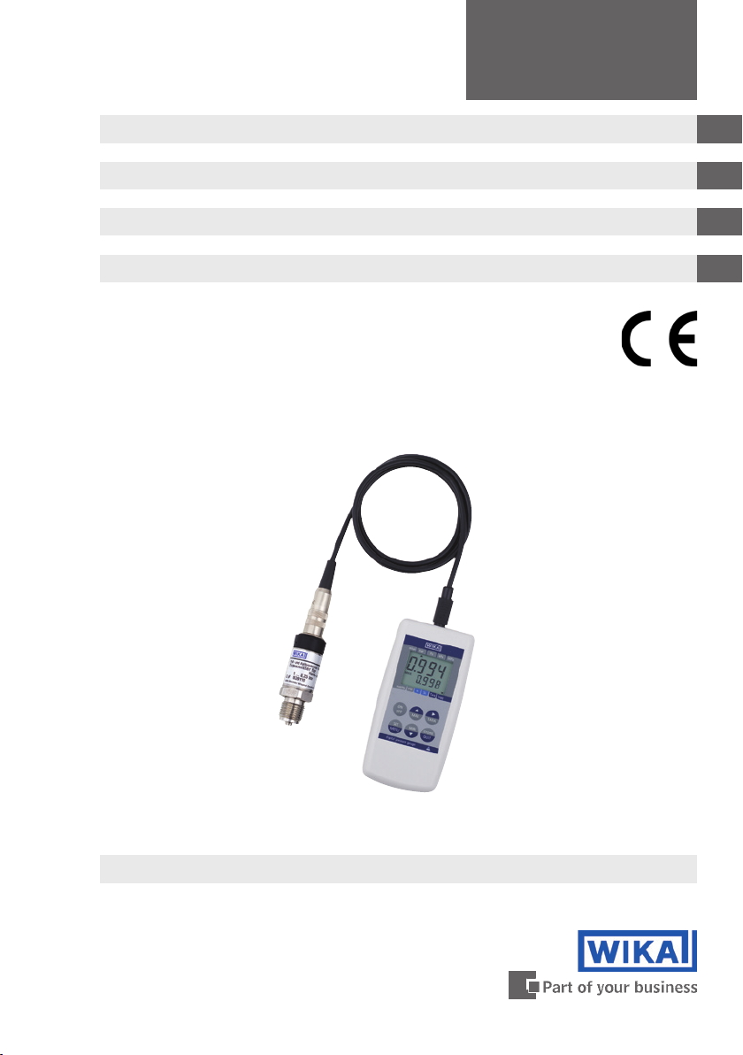
Hand-Held Pressure Indicator
Hand-Held Druckmessgerät
l'indicateur de pression portable
Manómetro portátil
CPH6200-S1
CPH6200-S2
GB
D
F
E
Model CPH6200-S1 / -S2
Page 2

Hand-Held Pressure Indicator Page 2 - 25
GB
D
Hand-Held Druckmessgerät Seite 26 - 49
F
l'indicateur de pression portable Page 50 - 73
E
Manómetro portátil Página 74 - 97
Information
This symbol provides you with information, notes and tips.
Warning!
This Symbol warns you against actions that can cause injury to
people or damage to the instrument.
11221780.1.3 01/2009 GB/D/F/E
2
Page 3

Hand-Held Pressure Indicator
CPH6200-S1 / CPH6200-S2
Contents
1. General 4
1.1 General safety instructions 5
1.2 Operation and maintenance advice 6
1.3 Electrical connections 7
1.4 Display 8
1.5 Basic operation 8
2. Configuration 12
2.1 (Unit) Choice of pressure units 13
2.2 (SL) Sea-level correction for absolute pressure sensors 13
2.3 (rAtE) Choice of measuring rates: „rAtE-Slo, -P.dEt, -FASt“ 13
2.3.1 rAtE-Slo: standard measuring 13
2.3.2 rAtE-P.dEt: peak detection 14
2.3.3 rAtE-FASt: fast filtered measuring 14
2.4 Averaging function 14
2.5 Zero correction sensor 1 (OFS.1) and sensor 2 (OFS.2) 15
2.6 Span correction sensor 1 (SCL.1) and sensor 2 (SCL.2) 15
2.7 (P.oFF) Power off function 15
2.8 (Out) Output 15
2.8.1 (Adr.) Serial communications address 15
2.8.2 (dAC.) Analogue output – scaling with dAC.0 and dAC.1 16
2.9 (AL.) Alarm 16
2.10 (CLOC) Real time clock 17
3. Operation of logger 17
3.1 “Func-Stor“: Storing discrete measurements 17
3.2 “Func-CYCL“: Automatic datalogging with adjustable cycletime
4. The serial interface 21
5. Available pressure sensors 21
6. Fault and system messages 22
7. Calibration services 23
8. Specifications 23
9. Accessories 25
19
GB
11221780.1.3 01/2009 GB/D/F/E
WIKA Operating Instructions Hand-Held Pressure Indicator 3
Page 4

Hand-Held Pressure Indicator
CPH6200-S1 / CPH6200-S2
GB
11221780.1.3 01/2009 GB/D/F/E
WIKA Operating Instructions Hand-Held Pressure Indicator4
1. General
In the following chapters detailed information on the hand-held pressure
indicator CPH6200 and its proper use can be found.
Should you require further information, or should there be problems
which are not dealt within detail in the operating instructions, please
contact the address listed on the last page.
Factory calibration of the instrument is according to relevant international standards.
The warranty period for the CPH6200 hand-held pressure indicator is 24
months according to the general terms of supply of ZVEI.
The guarantee is void if the appliance is put to improper use or if the
operating instructions are not observed or if an attempt is made to open
the appliance.
We also point out that the content of these operating instructions
neither forms part of an earlier or existing agreement, assurance or
legal relationship nor is meant to change these. All obligations of WIKA
Alexander Wiegand GmbH & Co. KG result from the respective sales
contract and the general business terms of WIKA Alexander Wiegand
GmbH & Co. KG.
WIKA is a registered trade mark of WIKA Alexander Wiegand GmbH &
Co. KG. Names of companies or products mentioned in this handbook
are registered trade marks of the manufacturer.
We reserve the right to effect reasonable changes on the basis of technical improvements.
Any reproduction of this manual or parts thereof by any means is
prohibited.
Version key regarding firmware and respective manual.
Manual Firmware
V 1.1 V 4.0 - V 4.9
V 1.2 V 5.0 - V 6.0
V 1.3 > V 6.0
© 2005 Copyright WIKA Alexander Wiegand GmbH & Co. KG
Page 5

Hand-Held Pressure Indicator
CPH6200-S1 / CPH6200-S2
1.1 General safety instructions
This device has been designed and tested in accordance with the
relevant safety regulations for electronic devices. However, its
trouble-free operation and reliability cannot be guaranteed unless
the standard safety measures and special safety advise given in this
manual is followed when using the device.
1. Trouble-free operation and reliability of the device can only be
guaranteed so long as the device is not subjected to any climatic
conditions other than those stated under “8. Specification“.
2. The device and sensors must be handled with care (don‘t throw, hit,
etc.). Protect plugs and sockets from contamination.
3. If the device is moved from a cold to a warm environment, condensa
tion may cause the equipment to fail. You should therefore ensure the
device temperature has adjusted to the ambient temperature before
trying to switch it on.
4. If the instrument is to be connected to other devices (e.g. via serial
interface) care must be taken when designing the equipment connections. It is possible that internal wiring within the external device (e.g.
connection of GND to Earth) may cause excessive voltages which
could harm or destroy the instrument or other connected devices.
If the device is operated with a faulty mains power supply (e.g.
short circuit from mains voltage to output voltage) this could result
in dangerous voltages at the device (e.g. at the sensor socket or
serial interface).
5. If there is any risk whatsoever involved in using it, the device must be
switched off immediately and marked accordingly to prevent re-use.
GB
-
Operator safety may be at risk if:
There is visible damage to the device
The device is not working as specified
The device has been stored under unsuitable conditions for an
extended period of time.
If there is any doubt, please return the device to the manufacturer for
repair or maintenance.
6. Customers must not attempt to alter or repair the device themselves.
Please return the device to the manufacturer for any repair or maintenance.
7. Any operation not included in the following instructions or outside the
specifications must not be attempted.
11221780.1.3 01/2009 GB/D/F/E
WIKA Operating Instructions Hand-Held Pressure Indicator 5
Page 6
Hand-Held Pressure Indicator
CPH6200-S1 / CPH6200-S2
GB
11221780.1.3 01/2009 GB/D/F/E
WIKA Operating Instructions Hand-Held Pressure Indicator
6
1.2 Operation and maintenance advice
Battery operation
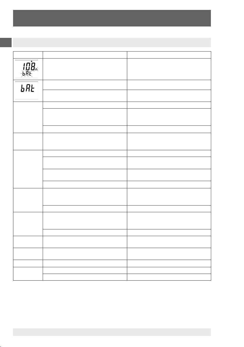
If ´bAt´ is shown in the lower display the battery is low and needs to
be replaced or recharged (using the appropriate battery charger as
shown in the current CPH6200 price list ).
The device will, however, work normally for a limited period. If ´bAt´
is shown in the upper display the voltage is too low to operate the
device; the battery will be completely flat.
A) If the device is not going to be used for some time, we advise that
the battery is removed.
B) The real time clock has to be set again after reconnect to the battery
Mains operation with power supply
When using a power supply please note that the operating voltage
must be 10.5 to 12 V DC. Do not use with higher voltages! Cheap
12 V-power supplies often have excessive no-load voltage, and
we therefore recommend using regulated-voltage power supplies.
Trouble-free operation can be ensured by using our own power
supply unit (see current CPH6200 price list). Before connecting the
power supply to the mains make sure that its operating voltage
matches the local mains voltage.
Connecting/Changing sensors
Only use sensors model CPT6200. Using other sensors can damage
the instrument! Switch off device before changing the sensor and
connect the sensor before turning the device back on, otherwise the
sensor may not be identified correctly.
The CPH6200 and the pressure transmitter are connected using a
discrete connecting cable. When changing the pressure transmitter,
always connect and disconnect at the transmitter end of the cable. To
connect the transmitter, rotate the plug till it locates in the guide slot,
allowing it to plug in. Then tighten the safety collar (by screwing it lightly
in a clockwise direction).
When connecting the cable to the CPH6200, the connector might not
locate properly in the socket. In this instance you should try holding the
plug by the cable strain relief, rather than by the connector housing. If
the plug is correctly located, it will slide in smoothly. To disconnect the
sensor hold it by the plug to release the connector lock. Do not pull the
cable to release it.
Page 7
Hand-Held Pressure Indicator
CPH6200-S1 / CPH6200-S2
For gauge sensors, the pressure compensation vent hole is found
at the top of the sensor housing. This vent (with integral membrane
seal) must be kept clear without fail.
Maintenance advice
Both the CPH6200 and sensors are manufactured using solidstate
technology, and contain no moving parts which could wear. If the
instrument housing has been opened, the warranty becomes invalid.
If cleaning is necessary, use a cloth wetted with mild detergent. Avoid
any solvents, caustic or abrasive substances.
As is normal for all measuring instruments, the accuracy of the device
should be tested at regular intervals (approx. once per year - see
Section 7).
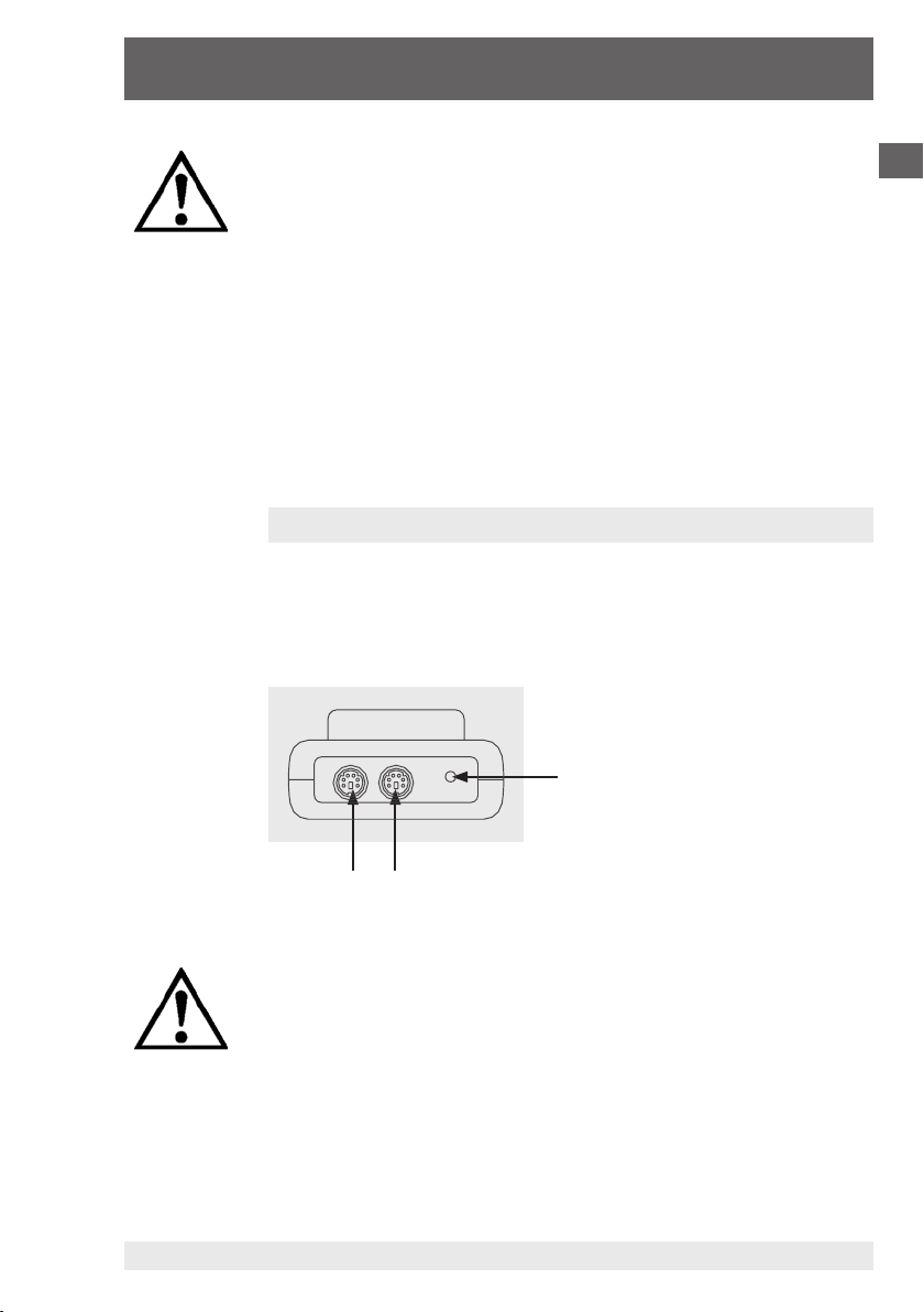
1.3 Electrical connections
On the upper edge of the device:
The connector sockets for attaching the CPH series pressure sensors,
CH1 and CH2 (CH2 only with the 2-channel version), are located on the
top edge of the CPH6200 (see Section 5), as is the socket for the WIKA
interface cable (see Section 4).
Connection for WIKA interface cable
or optional analogue output
GB
CH1 CH2 (only for 2-channel version: CPH6200-S2)
Operation as analogue output: connection via suitable cable.
The output mode has to be configured via menu and influences
battery life!
On the left side of the device:
The mains adapter socket for connecting the power supply unit (see
current CPH6200 price list) is located on the left side of the handheld
unit.
11221780.1.3 01/2009 GB/D/F/E
WIKA Operating Instructions Hand-Held Pressure Indicator 7
Page 8

Hand-Held Pressure Indicator
CPH6200-S1 / CPH6200-S2
GB
11221780.1.3 01/2009 GB/D/F/E
WIKA Operating Instructions Hand-Held Pressure Indicator
8
1.4 Display
1
2
6
3
4
5
1. Main display: shows the current measured value of CH1.
2. Lower display:
For 2-channel version shows the measured value
of CH2 or DIF (CH1-CH2). For 1 channel version it displays the min,
max or hold function values.
3. Logg:
shown if logger function is selected, flashes if cyclic logger is
running.
4. Tare:
5. SL:
6. Measuring unit:
indicates that tare function is activated.
indicates, that the sea level function is activated.
an arrow points to the chosen measuring unit.
1.5 Basic operation
On turning the device on; if the logger function is selected, the
integrated clock‘s time will be displayed briefly. If a zero point adjustment has been carried out, the display will indicate this by showing
"nuLL- Corr".
After changing the battery the menu for setting the clock is activated
automatically ('CLOC'). Check the clock and adjust if necessary (see
Section 2).
5
1
2
3
4
5
Page 9
Hand-Held Pressure Indicator
CPH6200-S1 / CPH6200-S2
1. On/Off key
2. Set/Menu: Enter Configuration Menu (press for 2 sec)
3. Tare: Activate tare function, zero point adjustment
4. Store/Quit: Activate hold function or logger function (see Section “3.
5. Min/Max: Display the respective min-/max-memory value in lower
Max-Function: Pressing ´Max´ shows the maximum measured value record-
Min-Function: Pressing ´Min´ shows the minimum measured value record-
Hold-Function:
Logger-Functions: Activated by the
Tare-Functions: By pressing ´Tare´, the display will be set to 0. All measure-
Operation of logger”.)
display
ed. Pressing it again hides it. To clear the max-memory press
the ´Max´ key for > 2 seconds.
ed. Pressing it again hides it. To clear the min-memory press
the ´Min´ key for > 2 seconds.
By pressing ´Store/Quit´ the instantaneous measured value
will be shown in the lower display. Pressing it again hides it.
(Only when the main menu item logger = ‘off‘ is selected).
been selected via the main menu (see Section “3. Operation
of logger”).
ments from then on will be displayed relative to the set tare
value. When the tare function is activated, the arrow ´Tare´
appears in the display. To deactivate the tare function press
´Tare´ for > 2 seconds.
´Store/Quit´
key, only if the logger has
Activating/deactivating tare clears the max- and min-memories.
Zero-Point Adjust: (for gauge pressure sensors only) If there is no pressure
applied to the pressure ports the device will display 0. If
there is a permanent offset (and the device is being used
under steady conditions), a permanent zero point adjustment can be carried out. To carry out the adjustment, press
´Tare´ for approx. 5 seconds. (Please note: A zeropoint
adjustment can only be made if the difference between the
display value and the factory calibration value is less than 2
%! E.g. for a measuring range of 0 ... 25 bar, => zeropoint
adjustment up to 0.5 bar possible). To revert to the factory
calibration, press ´Tare´ for approx. 15 seconds.
GB
A zero-point adjustment can only be carried out if the difference
between the value on display is less than 500 digits!
If a zero-point adjustment has been made, this will be signalled by the
message “nuLL-Corr“ being displayed briefly as the device is turned on.
Differential pressure: Pressing ´Set/Menu´ shows the difference between
the measured values of Channel 1 and Channel 2
(DIF=CH1-CH2) in the lower display. Pressing it again will
11221780.1.3 01/2009 GB/D/F/E
WIKA Operating Instructions Hand-Held Pressure Indicator 9
hide it (only with the 2-channel version and when 2 sensors
are connected).
Page 10
Hand-Held Pressure Indicator
CPH6200-S1 / CPH6200-S2
GB
11221780.1.3 01/2009 GB/D/F/E
WIKA Operating Instructions Hand-Held Pressure Indicator
10
Main Menu
Read*
Logg
Set
Conf
Set
CAL
Set
AL
(2 sec)
Stored data*
Recall of individually logged data and
respective time stamp (Func-STOR
configuration (see Section “3. Operation
of logger”).
Configuration
Unit** / Sea-Level** / Measuring rate** /
Power-off / interface-address
Calibration
Adjustment of zero and span
Alarm
Min/Max alarm visual with/without sound
Set**
Logg
Set
Cloc
(ring - shift)
* appears only if data (Func-STOR) is in the logger memory.
** appears only if the logger memory is empty (see Section “3. Operation of logger”).
Logger**
Switch from simple ‘Hold’ to ‘Logger’
function: Single-point values (STOR) or
Cyclic (CYCL)
System-clock
time / day & month / year
set parameter next store
parameter & quit
Page 11
Hand-Held Pressure Indicator
CPH6200-S1 / CPH6200-S2
Menu Param. Setting Meaning
„Menu“
SEt
ConF
SEt
CAL
►
▲ or ▼
Set Configuration: Generic settings
Unit
SL
Alti
rAtE
t.AVG
P.oFF
Out
Adr.
dAC.
dAC.0
dAC.1
mbar, bar, ... Unit: Unit of display
oFF / on Sea-level correction: on or off
-200 ... +9999 Altitude: Input of altitude above sea-level [m] (only if on)
Rate: Measuring rate (see chapter 2.3)
Slo Slow: Measuring rate (4 Hz filtered, low power consumption)
FASt Fast: Measuring rate, filtered (> 100 Hz)
P.dEt Peak detection: fast measuring rate, unfildered (> 100 Hz)
1 ... 120 Averaging interval in seconds, used by the averaging function off
oFF Averaging function deactivated
1 ... 120 Auto Power-Off delay in minutes. Device will automatically switch
oFF Auto Power-Off function inactive (continuous operation)
oFF Function of the output: No output function, lowest power
SEr Output is serial interface
dAC Output is analogue output 0 ... 1 V
01, 11 ... 91 Communicationsaddress of interface
CH1, CH2 or
CH DIF
eg. -5.00 ...
+5.00 mbar
eg. -5.00 ...
+5.00 mbar
itself off if, during this interval, no key is pressed, or there is no
serial communication.
consumption
Choice of the input to be the source for the analogue output (if
Out = dAC)
Enter desired value at which the analogue output potential should
be 0 V (if Out = dAC)
Enter desired value at which the analogue output potential should
be 1 V (if Out = dAC)
Set Calibration: Adjustment of sensors
OFS.1
SCL.1
OFS.2
SCL.2
Sensordep.,
e.g. -5.00 ...
+5.00 mbar
OFF Zero displacement inactive (=0.0 °)
eg. -5.00 ...
+5.00 mbar
OFF Scale correction factor inactive (=0.000)
Sensordep.,
e.g. -5.00 ...
+5.00 mbar
OFF Zero dispacement inactive (=0.0°)
eg. -5.00 ...
+5.00 mbar
OFF Scale correction factor inactive (=0.000)
The offset of sensor 1 will be displaced by this value to compensate for deviations in the probe or in the measuring device.
The measuring scale of sensor 1 will be changed by this factor
[%] to compensate deviations of temperature probe or measuring
device.
The offset of sensor 2 will be displaced by this value to compensate for deviations in the probe or in the measuring device.
The measuring scale of sensor 2 will be changed by this factor
[%] to compensate deviations of temperature probe or measuring
device.
GB
*, **
*, **
*, **
*
*
*
*
11221780.1.3 01/2009 GB/D/F/E
WIKA Operating Instructions Hand-Held Pressure Indicator 11
Page 12

Hand-Held Pressure Indicator
CPH6200-S1 / CPH6200-S2
GB
11221780.1.3 01/2009 GB/D/F/E
WIKA Operating Instructions Hand-Held Pressure Indicator12
Menu Param. Setting Meaning
„Menu“
SEt
AL.
SEt
LoGG
SEt
CLOC
►
▲ or ▼
Set Alarm: Alarm function configuration
AL.
[1,2,DIF]
AL.Lo
[1,2,DIF]
AL.Hi
[1,2,DIF]
Set Logger: Logger function configuration
Func
CYCL
Lo.Po
Set Clock: Setting of real time clock
CLOC
dAtE
YEAr
on Alarm function on, with audio alarm
no. So Alarm function on without audio alarm
oFF No alarm function
Min-Range ...
... AL.Hi
AL.Lo ...
... Max-Range
CYCL Cyclic: logger function ‘cyclic logger’
Stor Store: logger function ‘discrete value logger’
oFF No logger function
1 ... 3600 Cycle time for cyclic logger [seconds]
on / oFF Low-power logger with very low power consumption (only if
HH:MM Clock: set time hours:minutes
TT.MM Date: set time day.month
YYYY Year: set time year
Min alarm limit
(not when AL.oFF, Min-Range is the lower display range of the
connected sensor)
Max alarm limit
(not when AL.oFF, Max-Range is the upper display range of the
connected sensor)
*
*
*
*
*
*
cyclic logger with slow measuring rate)
*
* If there is existing data in the logger memory, the menus/parameters
cannot be accessed! If these need to be adjusted, the logger memory
must first be cleared! (see Section “3. Operation of logger”.)
** This menu can oly be invoked if a refering sensor is connected to
connection 1. When using a second sensor at connection 2 then
changes are taken over.
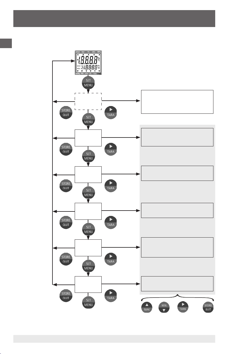
2. Configuration
To change device settings, press the ´Set/Menu´ key for 2 seconds. This
will access the configuration menu (main display: “SEt“).
Pressing the ´Set/Menu´ key again scrolls down the menus, pressing
the ´Tare´ key scrolls across to the associated parameters, which can
then be selected with the ´Tare´ key.
The parameters can be altered using the ´Min´ or ´Max´ keys. Pressing
the ´Set/Menu´ key again saves the settings and returns you to the main
configuration menu.
The ´Store/Quit´ key exits the configuration and returns you to standard
measuring mode.
Page 13

Hand-Held Pressure Indicator
CPH6200-S1 / CPH6200-S2
2.1 (Unit) Choice of pressure units
Depending on the pressure range, the pressure value can be displayed
in any one of the following units: mbar, bar, Pa, kPa, MPa, mmHg, inHg
or psi.
2.2 (SL) Sea-level correction for absolute pressure sensors
If an absolute pressure sensor is connected to the instrument, then the
device displays the true absolute pressure measured by the sensor. This
does not necessarily equate to the values given by weather stations,
which give the pressure at sea-level. Usually the sensor is situated
above sea-level and therefore, if the value at sea-level (zero) is to be
measured, the pressure loss resulting from the elevation above sealevel must be considered! To correct the displayed value activate the
“Sea-Level-Function“ (SL). (Setting is only possible, if the abs. Pressure
sensor is connected to sensor socket 1.) Then enter the sensor‘s height
above sea-level in metres (Alti). When activated, the display shows the
SL-arrow and the device displays the absolute pressure value relative to
sea-level.
When two absolute pressure sensors are connected, the sea level
function for both is corresponding to the setting of sensor 1.
2.3 (rAtE) Choice of measuring rates: “rAtE-Slo, -P.dEt, -FASt“
GB
Three options of measuring rate are supported. Two of them work with
high measuring frequencies of over 1000 measurements per second.
Whichever one of them was selected during configuration (see above),
this will be displayed in the lower display: “P.dEt“ or “FASt“.
2.3.1 rAtE-Slo: standard measuring
Measuring rate 4 Hz, averaging and filter functions are active.
Application: Measurement of slowly changing or static pressures, e.g.
leak testing, atmospheric pressure...
Highest accuracy, high noise immunity (EMI and unstable measuring
signals), low power consumption.
11221780.1.3 01/2009 GB/D/F/E
WIKA Operating Instructions Hand-Held Pressure Indicator 13
Page 14

Hand-Held Pressure Indicator
CPH6200-S1 / CPH6200-S2
GB
11221780.1.3 01/2009 GB/D/F/E
WIKA Operating Instructions Hand-Held Pressure Indicator14
2.3.2 rAtE-P.dEt: peak detection
Measuring rate > 1000 Hz, the value is displayed unfiltered.
Application with logger function: Measuring of pressure spikes or fluctuating pressures with a resolution of < 1.5 ms. The cyclic logger function
records the arithmetic mean value, the highest and the lowest peak
during the chosen time interval.
Higher power consumption, measuring is sensitive to noise (EMI,..).
2.3.3 rAtE-FASt: fast filtered measuring
Measuring rate > 1000 Hz, but the value is filtered slightly (higher noise
immunity than P.dEt, small peaks will be filtered out), apart from that,
identical behaviour to P.dEt.
2.4 Averaging function
The averaging function acts on the displayed values (LCD and serial
interface). It is completely independent of the averaging within the
logger function, please don‘t mix them up!
The averaging integrates the measured values during a chosen time
interval and then calculates the average display value. It is independent
of the selected measuring rate (slow, fast, peak detect).
Until sufficient values to calculate an average value have been collected
(dependant on selected averaging time), the upper display shows “----“,
the lower display shows a ´countdown´.
During an active low-power-logging procedure the average is always
deactivated.
Operation of min/max-value memory in conjunction with the averaging
function:
If averaging is activated and 'slow' measuring rate is selected (rAtE-
Slo), the min-/max-memory value relates to the average display
value.
If averaging is activated and 'fast' measuring rate is selected (rAtE-
FASt or P.dEt), the min-/max-memory value relates to the internal
measured values (pressure spikes can be detected).
Page 15

Hand-Held Pressure Indicator
CPH6200-S1 / CPH6200-S2
2.5 Zero correction sensor 1 (OFS.1) and sensor 2 (OFS.2)
A zero displacement can be carried out for the measured value:
value displayed = value measured - offset
Standard setting: ‘off‘ = 0.0°, i.e. no zero displacement will be carried
out. Together with the scale correction (see below) this factor is mainly
used to compensate for sensor deviations. Input is in the display unit.
2.6 Span correction sensor 1 (SCL.1) and sensor 2 (SCL.2)
The scale of the measuring can be influenced by this setting (factor is in %):
displayed value = measured value * (1+Scal/100)
Standard setting: ‘off‘ =0.000, i.e. value is not corrected. Together with
the zero displacement (see above) this factor is mainly used to compensate for sensor deviations.
2.7 (P.oFF) Power off function
If no key is pressed, and no serial communication occurs during the
interval set in configuration (P.off), the device will automatically switch
itself off to save battery power.
If P.oFF = oFF then the automatic power off is deactivated.
GB
2.8 (Out) Output
The output can be used as interface (RS-232 or USB) or as analogue
output (0 ... 1 V).
2.8.1 (Adr.) Serial communications address
This parameter has been included in preparation for future operation
with multi-point monitoring systems.
11221780.1.3 01/2009 GB/D/F/E
WIKA Operating Instructions Hand-Held Pressure Indicator 15
Page 16
Hand-Held Pressure Indicator
CPH6200-S1 / CPH6200-S2
GB
11221780.1.3 01/2009 GB/D/F/E
WIKA Operating Instructions Hand-Held Pressure Indicator16
2.8.2 (dAC.) Analogue output – scaling with (dAC.0) and (dAC.1)
Analogue output can not be used during logger recordings
With the dAC.0 and dAC.1 values the output can be rapidly scaled to
your efforts.
Keep in mind not to connect low-resistive loads to the output, otherwise the output value will be wrong and battery life is decreased. Loads
above ca 10 kΩ are uncritical. If the display exceeds the value set by
dAC.1, then the device will apply 1 V to the output. If the display falls
below the value set by dAC.0, then the device will apply 0 V to the
output. In case of an error (Err.1, Err.2, no sensor, etc.) the device will
apply slightly above 1 V to the output.
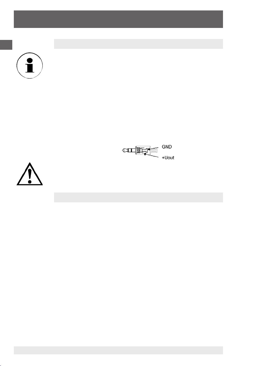
Plug wiring:
The 3rd contact has to be left floating! Only stereo plugs are
allowed!
2.9 (AL.) Alarm
There are three possible settings: Alarm off (AL.oFF), on with audio
alarm (AL.on), on without audio alarm (AL.no.So).
The following conditions will prompt an alarm to be displayed, if the
alarm function is activated (on or no.So):
Value is below lower alarm limit (AL.Lo) or above upper alarm limit
(AL.Hi).
Sensor error (Sens-Erro)
Low battery (bAt)
Fe 7: System error (always with sound)
When an alarm occurs, the alarm arrow flashes, and, during serial
communication, the 'PRIO'-flag is set within the transmitted message.
If the horn sound of one channel will be switched on/off (on or no.So),
then this horn sound setting will automatically be copied to the other
activated channels.
Page 17

Hand-Held Pressure Indicator
CPH6200-S1 / CPH6200-S2
2.10 (CLOC) Real time clock
The real time clock is needed for time-stamping each data point recorded within the logger function. As a result, the clock settings should be
checked regularly. If the battery has been replaced the appropriate
menu 'CLOC' will be accessed automatically.
3. Operation of logger
The device supports two different logger functions:
“Func-Stor“: each time the ´Store/Quit´ key is pressed a data point
will be recorded.
“Func-CYCL“: measurements will automatically be recorded at a
defined interval, set within the logger menu ‘CYCL‘ until
the logger is stopped or the logger memory becomes
full. Logging is started by pressing the ´Store/Quit´ key
for 2 seconds.
The logger records up to 3 measurement values for each interval:
Current or mean value (depending on logger setting, see below), Min-
Peak and Max-Peak. (Sensor 1, Sensor 2, difference)
To evaluate the data, WIKA's Data logger evaluation software GSOFT (V
2.3 or higher) must be used. The software also allows easy configuration
and operation of the logger.
GB
If the logger is selected (Func-STOR or Func-CYCL) the hold function is
deactivated; the ´Store/Quit´ key is then used solely for the operation of
the logger functions.
Min- and Max-Peak are, respectively, the minimum and the maximum
measured values during the last measurement interval. Therefore both
the instantaneous pressure values and the measured fluctuations can be
better analysed.
3.1 “Func-Stor“: Storing discrete measurements
In this mode, each time the ´Store/Quit´ key is pressed a measurement and its time stamp will be recorded. The data recorded can be
viewed either on the display (an additional menu item “REAd-LoGG“ is
displayed when scrolling through the Configuration menu) or through the
11221780.1.3 01/2009 GB/D/F/E
WIKA Operating Instructions Hand-Held Pressure Indicator 17
serial interface and a PC running the GSOFT-software.
Page 18

Hand-Held Pressure Indicator
CPH6200-S1 / CPH6200-S2
GB
11221780.1.3 01/2009 GB/D/F/E
WIKA Operating Instructions Hand-Held Pressure Indicator18
Max. number of measurements: 99
The data recorded includes the following values:
Sensor 1 instantaneous value at that data point
Sensor 1 Min-Peak, Max-Peak since last data point
Sensor 2* instantaneous value at that data point
Sensor 2* Min-Peak, Max-Peak since last data point
Instantaneous difference (Sensor 1 - Sensor 2)* at that data point
Min-Peak, Max-Peak of the difference (Sensor 1 - Sensor 2)*, Min-
Peak, Max-Peak since last data point
Time and date stamp of that data point
* Only for 2-channel version CPH6200-S2
After each recording “St. XX“ will be displayed for a short time. XX
represents the number of the data point.
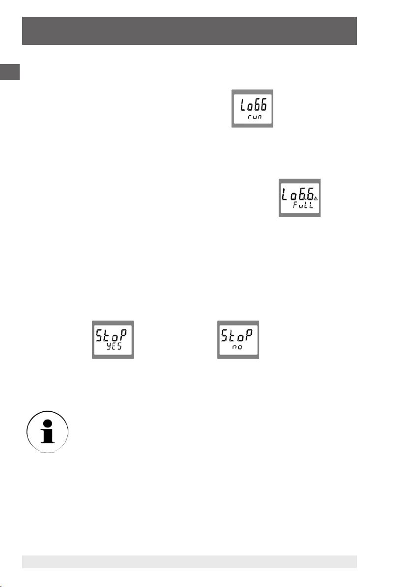
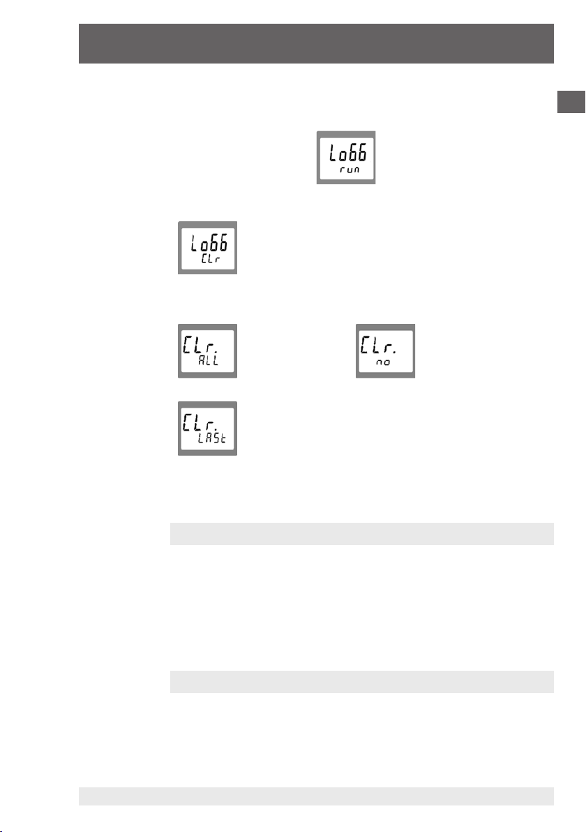
If the logger memory already contains data:
When the ´Store/Quit´ key is pressed for 2 seconds, the option to clear
the logger memory will be displayed:
clear clear nothing
all data points (cancel menu)
clear the last
data point
Use the ´Min´ or the ´Max´ key to display the required option. The
´Store/Quit´ key selects that choice.
If the logger memory is full, the display will show:
Viewing Recorded Measurements
Within the “LoGG-Stor“ function the measurements can be viewed
directly on the instrument display as well as through a computer (“FuncCYCL“ only allows for the data to be viewed on computer). Press the
´Set/Menu´ key for 2 seconds: The first menu displayed is now “rEAdLoGG“ (read logger data). By then pressing the ´Tare´ key, the last
measurement recorded will be displayed; pressing the ´Tare´ key again
scrolls between the different values related to this data point.
Pressing the ´Min´ key or ´Max´ key selects different data points.
Page 19

Hand-Held Pressure Indicator
CPH6200-S1 / CPH6200-S2
3.2 Func-CYCL“: Automatic datalogging with adjustable
cycle-time
The Logger cycle-time is adjustable (see Configuration). For example,
setting “CYCL“ = 60: A measurement is made every 60 seconds.
When the slow measurement “rAtE-Slo“ is chosen, additionally a low
power function is available: “Lo.Po“.
If “Lo.Po“ is on, the device only will take a measurement at the point of
time of the recording. In between the recordings the measuring shut‘s
down. This decreases the power consumption enormously and therefore is recommended e.g. for long time recordings where no mains
adapter is available.
Max. number of measurements: CPH6200-S1: 10000
CPH6200-S2: 4000
(at max. 64 recording sequences)
Cycle-time: 1 ... 3600 seconds (=1 h), selectable
from the configuration menu
A measurement contains:
Slow measuring rate (rAtE-SLo):
- Sensor 1 current value at that data point
- Sensor 1 Min-Peak, Max-Peak since last data point
- Sensor 2* instantaneous value at that data point
- Sensor 2* Min-Peak, Max-Peak since last data point
- Instantaneous difference (Sensor 1 - Sensor 2)* at that data point
- Min-Peak, Max-Peak of difference (Sensor 1 - Sensor 2)*, MinPeak, Max-Peak since last data point
GB
Fast measuring rate (rAtE-FASt, -P.dEt):
- Sensor 1 average since last data point
- Sensor 1 Min-Peak, Max-Peak since last data point
- Sensor 2* average since last data point
- Sensor 2* Min-Peak, Max-Peak since last data point
- Average difference (Sensor 1 - Sensor 2)* since last data point
- Min-Peak, Max-Peak of difference (Sensor 1 - Sensor 2)*,
Min-Peak, Max-Peak since last data point
* Only for 2-channel version CPH6200-S2
11221780.1.3 01/2009 GB/D/F/E
WIKA Operating Instructions Hand-Held Pressure Indicator 19
Page 20
Hand-Held Pressure Indicator
CPH6200-S1 / CPH6200-S2
GB
11221780.1.3 01/2009 GB/D/F/E
WIKA Operating Instructions Hand-Held Pressure Indicator20
Starting logging:
By pressing ´Store/Quit´ for 2 seconds the logger operation will be
called. The display will show:
By pressing ´Store/Quit´ again the recording will be initiated.
After that the display shows ‘St.XXXX‘ for a short time whenever a
measuring is recorded. XXXX is the number of the measuring 1 ... 4000
or 10000.
If the logger memory is full, the display will show:
The recording automatically will be stopped.
If the Low-Power-Logger-function is selected („Lo.Po = on“) the device
switches itself off as soon as the memory becomes full.
Stopping the logging manually:
By pressing the ´Store/Quit´ key, recording can be manually interrupted.
The following choice then appears:
Stop Do not stop
recording recording
The selection can be made by key: ´Max´ and key: ´Min´.
Key ´Store/Quit´ enters the choice.
If you try to switch off the instrument during a logging cycle, you
will also be asked if you wish to stop recording. The device can only
be switched off after the recording has been stopped!
The Auto-Power-Off-function is deactivated during logging!
Page 21
Hand-Held Pressure Indicator
CPH6200-S1 / CPH6200-S2
Clear data:
When the ´Store/Quit´ key is pressed for 2 seconds, the logger operation will be called.
The display will show:
By pressing the key ´Max´ or key ´Min´ the display will change to:
When ´Store/Quit´ is pressed, the choice for clearing the logger memory
will be displayed:
clear clear nothing
all recordings (cancel menu)
clear the last
recording sequence
The selection can be made by key ´Max´ or key ´Min´.
´Store/Quit´ enters the choice.
GB
4. The serial interface
For data transfer to a computer there are two electrically-isolated interface adapters available for the connection of the CPH6200 to a RS-232
or USB interface (USB-driver necessary).
WIKA‘s Data logger evaluation software GSOFT (see current CPH6200
price list) is used to display the data. To avoid transmission errors, there
are several security features implemented (e.g. CRC).
5. Available pressure sensors
The instrument has been designed so that all sensors model CPT6200
can be connected without the need for any configuration or recalibration. There is therefore a wide range of interchangeable sensors
11221780.1.3 01/2009 GB/D/F/E
WIKA Operating Instructions Hand-Held Pressure Indicator 21
available; with ranges of up to 1000 bar (see current price list for model
CPT6200 pressure transmitters).
Page 22
Hand-Held Pressure Indicator
CPH6200-S1 / CPH6200-S2
GB
11221780.1.3 01/2009 GB/D/F/E
WIKA Operating Instructions Hand-Held Pressure Indicator22
6. Fault and system messages
Display Meaning Remedy
Low battery power, device will only work
for a short while longer
Battery flat Replace battery
Replace battery
SEnS
Erro
or Err.9
- - - -
- - - -
No display
or strange
symbols,
device is not
responding to
input
Err.1
Err.2
Err.3
Err.4
Err.7
Err.11
Mains operation without battery: wrong
voltage
No sensor connected Switch off device and connect sensor
Connected sensor or device faulty If second sensor available, check if
Value extremely out of measuring range Check: pressure not within sensor range?
Logger data is being read by the serial
interface
Battery flat Replace battery
Mains operation without battery: wrong
voltage or polarity
System error Disconnect battery or power supply, wait
Instrument faulty Return to manufacturer for repair
Measured value above allowable range Check: Is the pressure outside the
Sensor faulty Return to manufacturer for repair
Measured value below allowable range Check: Is the pressure outside the
Sensor defective Return to manufacturer for repair
Display range overflow Check: value above 9999 -> to high to be
Display range underflow Check: value below ‚-2000‘ (Tare?) ->
System error Return to manufacturer for repair
Value coul not be calculated Choose different unit
Calculation overflow happened Choose different unit
Check power supply, change it if necessary
device is ok. Return defective device/
sensor to manufacturer for repair
When the data transfer is completed the
device will automatically return to normal
measuring display, no remedy necessary
Check power supply, change it if necessary
a while, re-connect
sensor‘s range? -> measured value to
high!
sensor‘s range? -> measured value to
low!
displayed!
to low!
Page 23

Hand-Held Pressure Indicator
CPH6200-S1 / CPH6200-S2
7. Calibration services
DKD-certificates - other certificates:
If the instrument requires calibration, we recommend returning it, along with its associated sensors, to the manufacturer. Only the manufacturer is able to verify the instrument‘s
basic settings and configuration, and if necessary correct them.
8. Specifications
Input 1: for CPH6200-S1; 2: for CPH6200-S2
Pressure range in bar 0.1 0.16 0.25 0.4 0.6 1.0 1.6 2.5 4.0 6.0
Overpressure safety in bar 1 1.5 2 2 4 5 10 10 17 35
Burst pressure in bar 2 2 2.4 2.4 4.8 6 12 12 20.5 42
Resolution in mbar 0.1 1
Pressure range in bar 10 16 25 40 60 100 160 250 400 600 1000
Overpressure safety in bar 35 80 50 80 120 200 320 500 800 1200 1500
Burst pressure in bar 42 96 250 400 550 800 1000 1200 1700 2400 3000
Resolution in bar 0.01 0.1 1
Type of pressure gauge {absolute 0.25 up to 16 bar & vacuum on request}
Accuracy of the measuring chain
Calibration* factory calibration certificate (optional: DKD calibration certificate)
Display large LCD display for display of 2 values and additional information
Range of display max. -19999 up to 99999, depending on sensors used
Units can be selected from the following: mbar, bar, Pa, kPa, MPa, mmHg, inHg, psi
CPH6200 Digital Instrument specific details:
Functions via key press Min-, Max-memory, Hold, Tare, Offset-correction, Logger (Start/Stop)
Functions via Menu Min-, Max-alarm (acoustic**/visual), Sea-level (barom. air pressure), Power-Off-
Data logger
Interface 1) (serial) RS-232 or USB interface via special interface cables
Power supply 9V-zinc-carbon battery, alternative**: 9V rechargeable battery or mains supply
Power consumption
Working temperature 0 ... 50 °C
Air humidity 0 ... 95 % relative humidity without moisture condensation
Storage temperature -20 ... +70 °C
Housing Impact-resistant ABS, membrane keyboard, transparent panels (CPH62I0 with
Weight Approx. 160 g
EMV- / CE-conformity The CPH6200 device corresponds to the essential protection requirements estab-
1) For the intrinsically safe version, the use of the interface is not permitted within an explosive atmosphere.
*) Calibrated in vertical mounting position with lower pressure connection.
**) Not available for the intrinsically safe version CPH62I0.
11221780.1.3 01/2009 GB/D/F/E
{} Items in curved brackets are optional extras at an additional price.
0.2 % FS +/- 1 digit at reference temperature of 20 °C (optional 0.1 %)
(dependent on range)
Function, measuring rate: 4/sec (“slow“); > 1000/sec (“fast“); > 1000/sec unfiltered (“peak-detect“) [via “peak-detect“ and min-/max-memory: pressure peaks
of 1.5 msec can be detected]
- discrete value-logger: up to 99 data points (incl. time-stamp) via key press
- cyclic-logger: automatic logging of up to 10000 values incl. time.
cycle-time: selectable between 1 ... 3600 seconds
Cycle-time slow: < 1.6 mA, fast: < 7.0 mA, Low-Power-Logger-Fct.: < 0.3 mA
cover)
lished in the regulations of the council for the approximation of legislation of the
member countries regarding electromagnetic compatibility (89/336/EWG).
GB
WIKA Operating Instructions Hand-Held Pressure Indicator 23
Page 24

Hand-Held Pressure Indicator
CPH6200-S1 / CPH6200-S2
GB
11221780.1.3 01/2009 GB/D/F/E
WIKA Operating Instructions Hand-Held Pressure Indicator24
CPT6200 Pressure Transmitter specific details:
Pressure connection G½ B; {flush diaphragm (G1 for 0.1 up to 1.6 bar) or various connection
Material wetted parts Wetted parts stainless steel, case stainless steel;
Internal transmission fluid Synthetic oil, (only for pressure ranges up to 16 bar or flush
One year stability 0.2 % of span at reference conditions
Permissible
- medium temperature
- ambient temperature 0 ... 50 °C
- storage temperature -40 ... +80 °C
Compensated range 0 ... 70 °C
Temperature coefficients
- mean TC of zero signal 0.2 %/10 K
- mean TC of span 0.2 %/10 K
Connection to CPH6200 via 1 m cable (plug and play); on request: up to 5 m
Weight approx. 220 g
2) O-ring made of Viton or EPDM for flush diaphragm with integrated cooling element.
3) The oxygen version must not be used with medium temperatures higher than 60 °C.
Cannot be manufactured for absolute pressure ranges < 1 bar abs.
{} Items in curved brackets are optional extras at an additional price.
adapters on request}
flush diaphragm version: stainless steel {Hastelloy C4};
O-Ring 2): NBR {FKM/FPM or EPDM}
diaphragm), {Halocarbon oil for oxygen applications}
{Listed by FDA for food industry}
3)
-25 ... +100 °C
3)
;
Page 25

Hand-Held Pressure Indicator
CPH6200-S1 / CPH6200-S2
9. Accessories
For accessories such as pressure pumps (pneumatic/hydraulic), flexible
pressure hose, pressure adapters, data logger-evaluation software Gsoft
or calibration software, power supply unit, battery charger, rechargeable
batteries, etc. see current “WIKA Testing and Calibration Technology
pricelist”.
GB
11221780.1.3 01/2009 GB/D/F/E
WIKA Operating Instructions Hand-Held Pressure Indicator 25
Page 26

D
Hand-Held Druckmessgerät
CPH6200-S1 / CPH6200-S2
11221780.1.3 01/2009 GB/D/F/E
WIKA Betriebsanleitung Hand-Held Druckmessgerät26
Information
Dieses Zeichen gibt Ihnen Informationen, Hinweise oder Tipps.
Warnung!
Dieses Symbol warnt Sie vor Handlungen, die Schäden an Personen
oder am Gerät verursachen können.
Page 27

Hand-Held Druckmessgerät
CPH6200-S1 / CPH6200-S2
Inhalt
1. Allgemeines 28
1.1 Allgemeine Sicherheitshinweise 29
1.2 Betriebs- und Wartungshinweise 30
1.3 Anschlüsse 31
1.4 Anzeige 32
1.5 Bedienung 32
2. Konfiguration des Gerätes 36
2.1 (Unit) Verschiedene Druckeinheiten 37
2.2 (SL) Höhenkorrektur bei Absolutdruck-Sensoren 37
2.3 (rAtE) Verschiedene Messarten: „rAtE-Slo, -P.dEt, -FASt“ 37
2.3.1 rAtE-Slo: Standardmessung 37
2.3.2 rAtE-P.dEt: Peak detection = Spitzenwertdetektion 38
2.3.3 rAtE-FASt: Fast = Schnelle Messung 38
2.4 Mittelwertbildung 38
2.5 Nullpunktkorrektur Sensor 1 (OFS.1) bzw. Sensor 2 (OFS.2) 39
2.6 Steigungskorrektur Sensor 1 (SCL.1) bzw. Sensor 2 (SCL.2) 39
2.7 (P.oFF) Abschaltverzögerung 39
2.8 (Out) Geräteausgang 39
2.8.1 (Adr.) Schnittstellen-Adresse 39
2.8.2 (dAC.) Analogausgang-Skalierung mit dAC.0 und dAC.1 40
2.9 (AL.) Alarm 40
2.10 (CLOC) Echtzeituhr 41
3. Bedienung der Loggerfunktion 41
3.1 „Func-Stor“: Einzelwerte speichern 41
3.2 „Func-CYCL“: Autom. Aufzeichnung mit einstellbarer Zykluszeit
4. Die serielle Schnittstelle 45
5. Verfügbare Drucksensoren 45
6. Fehler- und Systemmeldungen 46
7. Hinweis zum Kalibrierservice 47
8. Technische Daten 47
9. Zubehör 49
D
43
11221780.1.3 01/2009 GB/D/F/E
WIKA Betriebsanleitung Hand-Held Druckmessgerät 27
Page 28

D
Hand-Held Druckmessgerät
CPH6200-S1 / CPH6200-S2
11221780.1.3 01/2009 GB/D/F/E
WIKA Betriebsanleitung Hand-Held Druckmessgerät28
1. Allgemeines
In den folgenden Kapiteln erhalten Sie nähere Informationen zum
Hand-Held Messgerät CPH6200 und seinen ordnungsgemäßen Einsatz.
Sollten Sie weitere Informationen wünschen, oder treten besondere
Probleme auf, die in der Betriebsanleitung nicht ausführlich behandelt
werden, erhalten Sie Auskunft unter den auf der letzten Seite aufgelisteten Adressen.
Bei der Werkskalibrierung der Instrumente wurde sich an entsprechende
internationalen Normen orientiert.
Die Gewährleistungszeit für das Hand-Held Messgerät CPH6200
beträgt 24 Monate nach den Allgemeinen Lieferbedingungen des ZVEI.
Sämtliche Gewährleistungsansprüche verfallen, bei unsachgemäßer
Handhabung bzw. bei Nichtbeachtung der Betriebsleitungen oder bei
dem Versuch das Gerät zu öffnen.
Außerdem weisen wir darauf hin, dass der Inhalt dieser Betriebsanleitung nicht Teil einer früheren oder bestehenden Vereinbarung, Zusage
oder Rechtsverhältnisses ist oder diese abändern soll. Sämtliche
Verpflichtungen der WIKA Alexander Wiegand GmbH & Co. KG ergeben
sich aus dem jeweiligen Kaufvertrag und den Allgemeinen Geschäftsbedingungen der WIKA Alexander Wiegand GmbH & Co. KG.
WIKA ist ein eingetragenes Warenzeichen der WIKA Alexander Wiegand
GmbH & Co. KG.
Firmen- oder Produktnamen, die in diesem Handbuch erwähnt werden,
sind eingetragene Warenzeichen dieser Hersteller.
Zumutbare Änderungen aufgrund technischer Verbesserungen behalten
wir uns vor.
Eine Vervielfältigung dieses Handbuches oder Teilen davon ist untersagt.
Firmware - Betriebsanleitung-Versionsschlüssel
Manual Firmware
V 1.1 V 4.0 - V 4.9
V 1.2 V 5.0 - V 6.0
V 1.3 > V 6.0
© 2005 Copyright WIKA Alexander Wiegand GmbH & Co. KG
Page 29

Hand-Held Druckmessgerät
CPH6200-S1 / CPH6200-S2
1.1 Allgemeine Sicherheitshinweise
Dieses Gerät ist gemäß den Sicherheitsbestimmungen für elektronische Messgeräte gebaut und geprüft. Die Funktion und Betriebssicherheit des Gerätes kann nur dann gewährleistet werden, wenn
die nationalen Sicherheits- und Unfallverhütungsvorschriften sowie
die Sicherheitshinweise der Betriebsanleitung beachtet werden.
1. Die einwandfreie Funktion und Betriebssicherheit des Gerätes
kann nur unter den klimatischen Verhältnissen, die im Kapitel „8.
Technische Daten“ spezifiziert sind, eingehalten werden.
2. Gerät und Sensor müssen pfleglich behandelt werden (nicht werfen,
aufschlagen, etc.). Stecker und Buchsen sind vor Verschmutzung zu
schützen.
3. Wird das Gerät von einer kalten in eine warme Umgebung transpor
tiert, so kann durch Kondensatbildung eine Störung der Gerätefunktion eintreten. In diesem Fall muss die Angleichung der Gerätetemperatur an die Raumtemperatur vor einer erneuten Inbetriebnahme
abgewartet werden.
4. Konzipieren Sie die Beschaltung beim Anschluss an andere Geräte
besonders sorgfältig. Unter Umständen können interne Verbindungen in Fremdgeräten (z. B. Verbindung GND mit Erde) zu nicht
erlaubten Spannungspotentialen führen, die das Gerät selbst oder ein
angeschlossenes Gerät in seiner Funktion beeinträchtigen oder sogar
zerstören können.
Bei Betrieb mit einem defekten Netzgerät (z. B. Kurzschluss von
Netzspannung zur Ausgangsspannung) können am Gerät lebensgefährliche Spannungen auftreten!
5. Wenn anzunehmen ist, dass das Gerät nicht mehr gefahrlos betrie
ben werden kann, so ist es außer Betrieb zu setzen und vor einer
Wiederinbetriebnahme durch Kennzeichnung zu sichern.
-
-
D
Die Sicherheit des Benutzers kann durch das Gerät beeinträchtigt sein,
wenn es zum Beispiel:
Sichtbare Schäden aufweist.
Nicht mehr wie vorgeschrieben arbeitet.
Längere Zeit unter ungeeigneten Bedingungen gelagert wurde.
In Zweifelsfällen das Gerät grundsätzlich an den Hersteller zur Reparatur
bzw. Wartung einschicken.
6. Es dürfen am Gerät keine Veränderungen oder Reparaturen vom
Kunden vorgenommen werden. Zur Wartung oder Reparatur muss
das Gerät zum Hersteller eingesandt werden.
7. Ein anderer Betrieb als der in der folgenden Anleitung beschriebene
oder außerhalb der Spezifikationen, ist bestimmungswidrig und muss
11221780.1.3 01/2009 GB/D/F/E
WIKA Betriebsanleitung Hand-Held Druckmessgerät 29
deshalb ausgeschlossen werden.
Page 30

D
Hand-Held Druckmessgerät
CPH6200-S1 / CPH6200-S2
11221780.1.3 01/2009 GB/D/F/E
WIKA Betriebsanleitung Hand-Held Druckmessgerät30
1.2 Betriebs- und Wartungshinweise
Batteriebetrieb
Wird in der unteren Anzeige "bAt" angezeigt, so ist die Batterie
verbraucht und muss erneuert werden bzw. der Akku ist leer und
muss mit dem dafür vorgesehen Akkuladegerät (siehe aktuelle Preisliste CPH6200) geladen werden. Jedoch ist noch für eine gewisse Zeit
die Gerätefunktion gewährleistet. Wird in der oberen Anzeige "bAt"
angezeigt, so ist die Batterie ganz verbraucht. Batterie und Akku
sind nur sachgemäß zu benutzen und ordnungsgemäß den aktuellen,
nationalen Vorschriften zu entsorgen. Bei Lagerung des Gerätes über
50 °C muss die Batterie entnommen werden.
Wird das Gerät längere Zeit nicht benutzt, sollte die Batterie / der Akku
herausgenommen werden.
Die Uhrzeit muss nachher jedoch wieder neu eingestellt werden.
Netzgerätebetrieb
Beim Anschluss eines Netzgerätes muss dessen Spannung
zwischen 10,5 und 12 V DC liegen. Keine Überspannungen anlegen!
Einfache Netzgeräte können eine zu hohe Leerlaufspannung haben,
dies kann zu einer Fehlfunktion bzw. Zerstörung des Gerätes
führen! Wir empfehlen daher unser Netzgerät (siehe aktuelle Preisliste CPH6200) zu verwenden.
Vor dem Verbinden des Netzgerätes mit dem Stromversor-gungsnetz ist sicherzustellen, dass die am Netzgerät angegebene
Betriebsspannung mit der Netzspannung übereinstimmt.
Sensoren anstecken/wechseln
Nur Sensoren des Types CPT6200 verwenden! Mit anderen Sensoren
kann es zur Zerstörung des Messgerätes und des Sensors kommen.
Zum Sensorwechsel Gerät ausschalten. Sensor vor dem Einschalten
des Gerätes anstecken, sonst wird er vom Gerät evtl. nicht richtig
erkannt.
Digitalgerät und Sensor werden mittels eines separaten Verbindungskabels elektrisch miteinander verbunden. Für den Sensorwechsel sollte
bevorzugt der 7-polige Steckkontakt am Sensor benutzt werden.
Zum Anschluss eines Sensors stecken Sie die 7-polige Steckverbindung
am Sensor gemäß der Orientierungsführung zusammen und sichern Sie
diese durch die Überwurfhülse (Überwurfhülse ohne größeren Kraftaufwand in Uhrzeigersinn drehen).
Beim Anstecken des Kabels am Digitalgerät kann es vorkommen, dass
der Stecker nicht richtig in die Buchse einrastet. In diesem Fall den
Stecker beim Anstecken nicht an Steckerhülse sondern am Knickschutz
halten. Stecker nicht verkantet anstecken. Bei richtig angesetztem
Page 31

Hand-Held Druckmessgerät
CPH6200-S1 / CPH6200-S2
Stecker kann dieser ohne größeren Kraftaufwand eingesteckt werden.
Beim Abstecken des Sensors nicht am Kabel ziehen, sondern nur an der
Steckerhülse.
Im hinteren Teil des Sensorgehäuses befindet sich, bei Überdruckbzw. relativ Drucksensoren, das Loch für den Druckausgleich, diese
Öffnung (mit integrierter Membrane) muss unbedingt frei bleiben!
Wartung
Digitalgerät und Sensoren enthalten keinerlei Verschleißteile, so dass
das Öffnen der Geräte-Gehäuse nicht erforderlich ist und für die
Aufrechterhaltung der Gewährleistungsansprüche unbedingt unterbleiben sollte.
Für die Reinigung der Gehäuse-Oberflächen empfehlen wir ein weiches,
wenig fusselndes, in Seifenwasser angefeuchtetes Tuch.
Wie für Messmittel allgemein üblich, sollten sie in regelmäßigen Abständen (ca. 1 x jährlich) auf Einhaltung der Spezifikationen überprüft werden
(siehe Kapitel „7. Hinweis zum Kalibrierservice).
1.3 Anschlüsse
D
Am oberen Ende des Gerätes
befindet sich die Anschlussbuchse CH1 und CH2 (CH2 nur bei 2-Kanal
Ausführung) zum Anschluss der Drucksensoren der CPH-Serie (siehe
Kapitel 5) und die Buchse zum Anschluss des WIKA Schnittstellenkabels (siehe Kapitel 4).
Anschluss für WIKA Schnittstellenkabel (RS-232/USB) oder Optionaler
Analogausgang
CH1 CH2 (nur bei 2-Kanal-Ausführung: CPH6200-S2)
Betrieb als Analogausgang: Anschluss über entsprechendem
Analogkabel. Achtung: Die jeweilige Betriebsart muss konfiguriert
werden und beeinflußt die Batterielebensdauer!
An der linken Seite des Gerätes
befindet sich die Netzbuchse zum Anschluss des erhältlichen Netzge-
11221780.1.3 01/2009 GB/D/F/E
WIKA Betriebsanleitung Hand-Held Druckmessgerät 31
rätes (siehe aktuelle Preisliste CPH6200).
Page 32

D
Hand-Held Druckmessgerät
CPH6200-S1 / CPH6200-S2
11221780.1.3 01/2009 GB/D/F/E
WIKA Betriebsanleitung Hand-Held Druckmessgerät32
1.4 Anzeige
1. Hauptanzeige: zeigt den aktuellen Messwert an.
2. Nebenanzeige:
bzw. DIF an und bei 1-Kanal Ausführung werden hier Min-, Max- oder
Holdwerte angezeigt.
3. Logg:
bei laufendem Logger
4. Tara:
erscheint bei aktivierter Höhenkorrektur (Sea-Level)
5. SL:
6. Einheiten:
1
2
6
3
4
5
zeigt bei 2-Kanal Ausführung den Messwert von CH2
erscheint, falls Loggerfunktion ausgewählt wurde und blinkt
signalisiert, ob Tara-Funktion aktiviert ist.
ein Pfeil zeigt auf die gewählte Messeinheit
1.5 Bedienung
Beim Einschalten wird, falls eine Loggerfunktion gewählt wurde, kurz
die Uhrzeit angezeigt. Falls ein Nullpunktabgleich durchgeführt worden
ist, wird dies mit der Anzeige „nuLL-Corr“ signalisiert.
Nach einem Batteriewechsel erscheint automatisch das UhrzeitEinstellungs-Menü (‚CLOC‘). Überprüfen und korrigieren Sie ggf. die
Uhrzeit (siehe Kapitel „2. Konfigurieren des Gerätes“).
5
1
2
3
4
5
Page 33

Hand-Held Druckmessgerät
CPH6200-S1 / CPH6200-S2
1. Ein-/Ausschalter
2. Set/Menu: Aufruf der Konfiguration
3. Tara: Aufruf der Tara-Funktion, Nullpunktabgleich
4. Store/Quit: Aufruf der Hold-Funktion bzw. der Loggerfunktionen
(Siehe Kapitel „3. Bedienung der Loggerfunktion“.)
5. min/max: Aufruf des Min- bzw. Max-Speichers
D
Max-Speicher: Die Taste ´Max´ zeigt den maximal gemessenen Wert.
Min-Speicher: Die Taste ´Min´ zeigt den minimal gemessenen Wert.
Hold-Funktion: Durch Drücken der Taste ´Store/Quit´ wird der letzte
Logger-Funktionen: Aktivierung über ´Store/Quit´-Taste, falls im Haupt-
Tara-Funktion: Durch Drücken der Taste ´Tara´ wird die Anzeige auf 0
Beim Aktivieren von Tara werden Max.- & Min.-Speicher gelöscht.
Nullpunktabgleich: (für Relativdruck-Sensoren) Wenn an den Druckstut-
Erneutes Drücken blendet ihn wieder aus. Zum Löschen
des Max-Wertes ´Max´ für > 2 sec. drücken.
Erneutes Drücken blendet ihn wieder aus. Zum Löschen
des Min-Wertes ´Min´ für > 2 sec. drücken.
Messwert in der unteren Anzeige gehalten. Erneutes
Drücken blendet den Wert wieder aus (nur falls Logger
deaktiviert).
menü von Hold auf eine Logger Funktion umgeschaltet
wurde (siehe Kapitel „3. Bedienung der Loggerfunktion“).
gesetzt. Alle Messungen werden von nun an relativ zu
dem gesetzten Tara-Wert angezeigt. Ist die Tara-Funktion
aktiviert, wird der Pfeil ´Tara´ angezeigt. Zum Deaktivieren
die Taste ´Tara´ für > 2 sec. gedrückt halten.
zen kein Druck angelegt wird zeigt das Gerät 0 an. Sollte
jedoch doch eine ständige Abweichung vorhanden sein
(bei Betrieb in störungsfreien Umgebungsbedingungen),
so besteht die Möglichkeit einen dauerhaften Nullpunktabgleich durchzuführen. Um einen Nullpunktabgleich
durchzuführen die Taste ´Tara´ für ca. 7 sec. lang drücken.
(Nur möglich, wenn Anzeigewert weniger als 2 % von
der Werkskalibrierung abweicht, z. B. 0 ... 25 bar ->
Nullpunktabgleich bis 0,5 bar möglich). Wiederherstellen
der Werkskalibrierung: ´Tara´-Taste für ca. 15 sec. lang
drücken.
Abgleich ist nur möglich, wenn Abweichung weniger als 500 Digits beträgt.
Wurde ein Nullpunktabgleich durchgeführt, wird dies beim Einschalten des
Gerätes mit der Meldung „nuLL-Corr“ signalisiert.
Differenzbildung: Durch Drücken der ´Set/Menu´-Taste wird in
11221780.1.3 01/2009 GB/D/F/E
WIKA Betriebsanleitung Hand-Held Druckmessgerät 33
der Nebenanzeige die Differenz von Kanal 1- Kanal 2
(DIF=CH1-CH2) angezeigt. Erneutes Drücken macht den
Vorgang wieder rückgängig. (nur bei 2 Kanal Ausführung
und 2 angeschlossenen Sensoren).
Page 34

D
Hand-Held Druckmessgerät
CPH6200-S1 / CPH6200-S2
11221780.1.3 01/2009 GB/D/F/E
WIKA Betriebsanleitung Hand-Held Druckmessgerät34
Menüführung des Hauptmenüs
(2 sec)
Read*
Logg
Set
Conf
Set
CAL
Set
AL
Set**
Logg
Speicherdaten*
Aufruf der gespeicherten EinzelwertloggerDaten (Siehe Kapitel „3. Bedienung der
Loggerfunktion“)
Konfiguration
Einheit ** / Sea-Level** / Messrate** /
Power-off / Schnittstellen-Adresse
Justage
Von Nullpunkt und Spanne
Alarm
Min/Max Alarm visuell mit/ohne Hupe
Logger**
Umschalten von Hold auf Logger Fkt:
Einzelwert (STOR) bzw. zyklisch (CYCL)
Set
Cloc
(ring - shift)
* erscheint nur, wenn Daten im Einzelwert-Logger gespeichert sind
** erscheint nur, wenn keine Daten im Logger gespeichert sind (siehe „3. Bedienung der Loggerfunktion“).
System-Uhr
Uhrzeit / Tag & Monat / Jahr
Parameter Nächster Übernahme
einstellen Parameter & Abbruch
Page 35

Hand-Held Druckmessgerät
CPH6200-S1 / CPH6200-S2
Menu Param. Werte Bedeutung
„Menu“
SEt
ConF
SEt
CAL
►
▲ oder ▼
Set Configuration: Allgemeine Einstellungen
Unit
SL
Alti
rAtE
t.AVG
P.oFF
Out
Adr.
dAC.
dAC.0
dAC.1
mbar, bar, ... Unit: Anzeigeeinheit
oFF / on Sea-Level: Meereshöhen-Korrektur an/aus
-200 ... +9999
Slo
FASt Fast: schnelle Messung, gefiltert (> 100 Hz)
P.dEt Peak detection: schnelle Messung, ungefiltert (> 100 Hz)
1 ... 120 Zeit in Sekunden, über der die Mittelwertbildung errechnet wird
oFF Mittelwertbildung deaktiviert
1 ... 120 Auto Power-Off (Abschaltverzögerung) in Minuten. Wird keine
oFF Automatische Abschaltung deaktiviert (Dauerbetrieb)
oFF Keine Ausgabefunktion, niedrigster Stromverbrauch
SEr Geräteausgang ist serielle Schnittstelle
dAC Geräteausgang ist Analogausgang 0 ... 1 V
01, 11 ... 91 Basisadresse der Schnittstelle
CH1, CH2 or
CH DIF
eg. -5.00 ...
+5.00 mbar
eg. -5.00 ...
+5.00 mbar
Altitude: Meereshöhen-Korrektur in [m] (nur wenn SL an)
Rate: Messgeschwindigkeit (siehe Kapitel 2.3)
Slow: langsame Messung (4 Hz gefiltert, geringer Stromverbrauch)
Taste gedrückt und findet kein Datenverkehr über die Schnittstelle statt, so schaltet sich das Gerät nach Ablauf dieser Zeit
automatisch ab.
Messeingang, der für die Analogausgabe verwendet werden soll
(nur bei Out = dAC)
Nullpunkteinstellung bei Out = dAC: Eingabe des Messwertes bei
dem der Analogausgang 0 V ausgeben soll (nur bei Out = dAC)
Steigungseinstellung bei Out = dAC: Eingabe des Messwertes bei
dem der Analogausgang 1 V ausgeben soll (nur bei Out = dAC)
Set Calibration: Sensorabgleich
OFS.1
Sensordep.,
e.g. -5.00 ...
+5.00 mbar
Der Nullpunkt des Sensors 1 wird um diesen Wert
verschoben, damit können Fühler- und Messgeräte-Abweichungen ausgeglichen werden.
OFF Nullpuntverschiebung ist deaktiviert (= 0.0 °)
SCL.1
eg. -5.00 ...
+5.00 mbar
Die Mess-Steigung des Sensors 1 wird um diesen Faktor [%]
verändert, damit können Fühler- und Messgeräte-Abweichungen ausgeglichen werden.
OFF Faktor ist deaktiviert (= 0.000)
OFS.2
Sensordep.,
e.g. -5.00 ...
+5.00 mbar
Der Nullpunkt des Sensors 2 wird um diesen Wert
verschoben, damit können Fühler- und Messgeräte-Abweichungen ausgeglichen werden.
OFF Nullpunktverschiebung ist deaktiverit (= 0.0°)
SCL.2
eg. -5.00 ...
+5.00 mbar
Die Mess-Steigung des Sensors 2 wird um diesen Faktor [%]
verändert, damit können Fühler- und Messgeräte-Abweichungen ausgeglichen werden.
OFF Faktor ist deaktiviert (= 0.000)
*, **
*, **
*, **
*
*
*
*
D
11221780.1.3 01/2009 GB/D/F/E
WIKA Betriebsanleitung Hand-Held Druckmessgerät 35
Page 36

D
Hand-Held Druckmessgerät
CPH6200-S1 / CPH6200-S2
11221780.1.3 01/2009 GB/D/F/E
WIKA Betriebsanleitung Hand-Held Druckmessgerät36
Menu Param. Werte Bedeutung
►
▲ oder ▼
Set Alarm: Einstellung der Alarmfunktion
AL.
[1,2,DIF]
AL.Lo
[1,2,DIF]
AL.Hi
[1,2,DIF]
Set Logger: Einstellung der Loggerfunktion
Func
CYCL
Lo.Po
Set Clock: Einstellung der Echtzeituhr
CLOC
dAtE
YEAr
on Alarm Sensor an, mit Hupe
no. So Alarm Sensor an, ohne Hupe
oFF Keine Alarmfunktion
Min-Range ...
... AL.Hi
AL.Lo ...
... Max-Range
CYCL Cyclic: Loggerfunktion zyklischer Logger
Stor Store: Loggerfunktion Einzelwertlogger
oFF Keine Loggerfunktion
1 ... 3600 Zykluszeit in [Sekunden] bei zyklischem Logger
on / oFF Low-Power-Logger mit geringer Stromaufnahme (nur bei
HH:MM Clock: Einstellen der Uhrzeit Stunden:Minuten
TT.MM Date: Einstellen des Datums Tag.Monat
YYYY Year: Einstellen der Jahreszahl
„Menu“
SEt
AL.
SEt
LoGG
SEt
CLOC
Min-Alarm-Grenze (nicht wenn AL.oFF, Sensor-Min ist die untere
Anzeigebereichs-Grenze des angesteckten Sensors)
Max-Alarm-Grenze (nicht wenn AL.oFF, Sensor-Max ist die obere
Anzeigebereichs-Grenze des angesteckten Sensors)
*
*
*
*
*
*
zyklischem Logger und langsamer Messung)
*
* Befinden sich Daten im Loggerspeicher, können diese Menüpunkte,
nicht aufgerufen werden. Sollen diese verändert werden, müssen
zunächst die Daten gelöscht werden (siehe Kapitel 3).
** Menü kann nur aufgerufen werden, wenn ein entsprechender Sensor
an Anschluss 1 angesteckt ist. Bei einem zweiten entsprechenden
Sensor an Anschluss 2 werden die Einstellungen übernommen.
2. Konfigurieren des Gerätes
Zum Ändern von Einstellungen 2 sec lang die Taste ´Set/Menu´
drücken, dadurch wird das Menü (Hauptanzeige „SEt“) aufgerufen.
Mit ´Set/Menu´ wählen Sie das Menü und mit ´Tara´ können Sie zu den
zugehörigen Parametern springen, den Sie dann verändern können.
Die Einstellung der Parameter erfolgt mit den Tasten ´Min´ oder ´Max´.
Erneutes Drücken von ´Set/Menu´ wechselt zurück zum Hauptmenü
und speichert die Einstellungen.
Mit ´Store/Quit´ wird die Konfiguration beendet.
Page 37

Hand-Held Druckmessgerät
CPH6200-S1 / CPH6200-S2
2.1 (Unit) Verschiedene Druckeinheiten
Abhängig vom Messbereich des aktuellen Drucksensors kann die
Einheit: mbar, bar, Pa, kPa, MPa, mmHg, inHg oder psi gewählt werden.
2.2 (SL) Höhenkorrektur bei Absolutdruck-Sensoren
Bei angeschlossenem Absolutdrucksensor misst das Gerät den
Absolutdruck. Dieser ist jedoch nicht mit dem von Wetterstationen
angegebenen „Luftdruck auf Meereshöhe“ zu verwechseln! Bei dieser
Druckangabe wird die höhenbedingte Luftdruckabnahme herausgerechnet. Das Gerät ist in der Lage, diese Luftdruck-Höhenkorrektur vorzunehmen. Aktivieren Sie hierzu die „Sea-Level-Funktion“ (SL).
(Einstellung ist nur möglich wenn ein Absolutdrucksensor an Sensorbuchse 1 angeschlossen ist.)
Bei aktivierter Sea-Level-Funktion wird unten in der Anzeige der Pfeil
für „SL“ angezeigt. Wurde die Höhe des Aufenthaltsortes über dem
Meeresspiegel eingegeben (Alti), zeigt das Gerät jetzt den Absolutdruck
auf Meereshöhe bezogen an.
Bei 2 angesteckten Absolutdrucksensoren wird die Sea-Level-Funktion
für beide Sensoren entsprechend den Einstellung von Sensor 1 durchgeführt
2.3 (RatE) Verschiedene Messarten: „rAtE-Slo, -P.dEt, -FASt“
Das Gerät unterstützt 3 verschiede Messarten für verschiedene Anwendungszwecke. Zwei davon arbeiten mit einer erhöhten Messfrequenz
von > 1000 Messungen/sek. Ist eine der beiden aktiv, wird in der unteren
Anzeige entsprechend P.dEt oder FASt angezeigt.
D
2.3.1 rAtE-Slo: Standardmessung
Messfrequenz 4 Hz, Mittelungsverfahren und Messfilter sind aktiv.
Anwendungsbereich: Messen von langsamen Druckänderungen
und statischen Drücken, z. B. Kalibrierungen, Dichtheitsprüfungen,
Luftdruckmessungen u.ä. höchste Messgenauigkeit, störungsunempfindlich, niedriger Stromverbrauch.
11221780.1.3 01/2009 GB/D/F/E
WIKA Betriebsanleitung Hand-Held Druckmessgerät 37
Page 38

D
Hand-Held Druckmessgerät
CPH6200-S1 / CPH6200-S2
11221780.1.3 01/2009 GB/D/F/E
WIKA Betriebsanleitung Hand-Held Druckmessgerät38
2.3.2 rAtE-P.dEt: Peak detection = Spitzenwertdetektion
Messfrequenz > 1000 Hz, das Messsignal wird ungefiltert wiedergegeben. Anwendungsbereich in Verbindung mit Logger-Funktion: Messen
von Spitzendrücken und schnellen Druckschwankungen mit einer
Auflösung < 1,5 ms. Bei zyklischer Loggerfunktion werden jeweils der
arithmetische Mittelwert, der höchste und der niedrigste Druck des
Intervalls aufgezeichnet.
Erhöhter Stromverbrauch, Messung ist störungsempfindlich (auch
gegenüber elektromagnetischen Störungen).
2.3.3 rAtE-FASt: Fast = Schnelle Messung
Messfrequenz > 1000 Hz, aber das Messsignal wird gefiltert wiedergegeben (weniger störungsempfindlich, kurze Spitzen werden‚ herausgefiltert), ansonsten identisch zu „rAtE-P.dEt“.
2.4 Mittelwertbildung
Die Mittelwertbildung bezieht sich auf die Anzeigewerte (Display und
Schnittstelle). Sie ist komplett unabhängig von der Mittelwertbildung der
Loggerfunktion (bitte nicht verwechseln!).
Die Mittelwertbildung integriert über eine einstellbare Zeit sämtliche
Messwerte und errechnet dann den resultierenden gemittelten Anzeigewert. Die Funktion ist unabhängig von der Messart (schnelle/langsame
Messung).
Solange noch nicht eine ausreichend lange (eingestellte Zeit in Sekunden) gemessen wurde um den Mittelwert errechnen zu können, wird
in der Anzeige „----“ angezeigt, in der unteren Anzeige erscheint ein
‚Countdown‘.
Während des Low-Power-Loggerbetriebes ist die Mittelwertbildung
immer deaktiviert.
Funktion des Min/Max-Wertspeichers in Kombination mit der Mittelwertbildung:
Ist die Mittelwertbildung aktiviert, und die Messfunktion langsame
Messung (rAtE-Slo) gewählt, so bezieht sich der Min/Max-Wertspeicher auf die gemittelten Anzeigewerte.
Ist die Mittelwertbildung aktiviert, und eine schnelle Messfunktion
(rAtE-FASt oder -P.dEt) gewählt, so bezieht sich der Min/MaxWertspeicher auf die intern gemessenen Werte (> 1000 Hz Messfrequenz).
Page 39

Hand-Held Druckmessgerät
CPH6200-S1 / CPH6200-S2
2.5 Nullpunktkorrektur Sensor 1 (OFS.1) bzw. Sensor 2 (OFS.2)
Für die entsprechende Messung kann eine Nullpunktverschiebung
vorgenommen werden:
Angezeigter Wert = gemessener Wert – Offset
Standardeinstellung: ‚off‘ = 0.0, d.h. es wird keine Korrektur vorgenommen. Die Nullpunktkorrektur wird zusammen mit der Steigungskorrektur
(s.u.) vor allem zum Abgleich von Sensorabweichungen verwendet. Die
Eingabe erfolgt in der eingestellten Anzeigeeinheit.
2.6 Steigungskorrektur Sensor 1 (SCL.1) bzw. Sensor 2 (SCL.2)
Die Steigung der entsprechenden Messung kann mit diesem Faktor
beeinflusst werden (Faktor ist in %):
Angezeigter Wert = (gemessener Wert – Offset) * (1+Scal/100)
Standardeinstellung: ‚off‘ =0.000, d.h. es wird keine Korrektur vorgenommen. Die Steigungskorrektur wird zusammen mit der Nullpunktkorrektur (s.o.) vor allem zum Abgleich von Sensorabweichungen verwendet.
2.7 (P.oFF) Abschaltverzögerung
Wird für die Dauer der Abschaltverzögerung keine Taste gedrückt bzw.
keine Schnittstellenkommunikation vorgenommen, so schaltet sich das
Gerät automatisch ab.
Die Abschaltverzögerung ist zwischen 1 und 120 min wählbar.
Ist P.oFF = oFF, so ist die Abschaltverzögerung deaktiviert.
D
2.8 (Out) Geräteausgang
Der Ausgang kann entweder als Schnittstelle (RS-232 oder USB) oder
als Analogausgang (0 ... 1 V) verwendet werden.
2.8.1 (Adr.) Schnittstellen-Adresse
In Vorbereitung für Multiplexerbetrieb.
11221780.1.3 01/2009 GB/D/F/E
WIKA Betriebsanleitung Hand-Held Druckmessgerät 39
Page 40

D
Hand-Held Druckmessgerät
CPH6200-S1 / CPH6200-S2
11221780.1.3 01/2009 GB/D/F/E
WIKA Betriebsanleitung Hand-Held Druckmessgerät40
2.8.2 (dAC.) Analogausgang-Skalierung mit dAC.0 und dAC.1
Der Analogausgang kann nicht bei einer Loggeraufzeichnung verwendet
werden.
Mit dAC.0 und dAC.1 kann der Analogausgang sehr einfach skaliert
werden.
Es ist darauf zu achten, dass der Analogausgang nicht zu stark belastet
wird, da sonst der Ausgangswert verfälscht werden kann und die Stromaufnahme des Gerätes entsprechend steigt. Belastungen bis ca. 10 kΩ
sind unbedenklich. Überschreitet die Anzeige den mit dAC.1 eingestellten Wert, so wird 1 V ausgegeben Unterschreitet die Anzeige den mit
dAC.0 eingestellten Wert, so wird 0 V ausgegeben. Im Fehlerfall (Err.1,
Err.2, ----, usw.) wird am Analogausgang eine Spannung leicht über 1 V
ausgegeben.
Klinkensteckerbelegung:
Der 3. Anschluß darf nicht benutzt werden! Nur Stereo-Klinkenstecker sind zulässig!
2.9 (AL.) Alarm
Es sind 3 Einstellungen möglich: aus (AL.oFF), an mit Hupe (AL.on), an
ohne Hupe (AL.no.So).
Bei folgenden Bedingungen wird bei aktiver Alarmfunktion (on oder
no.So) ein Alarm ausgegeben:
Untere (AL.Lo) bzw. obere Alarmgrenze (AL.Hi) unter- bzw. überschritten.
Sensorfehler (Sens-Erro)
Schwache Batterie (bAt)
Fe 7: Systemfehler (wird immer mit Hupe gemeldet)
Im Alarmfall blinkt die Anzeige, bei Schnittstellenzugriffen wird das
‚PRIO'-Flag gesetzt.
Wird von einem Alarmkanal die Hupe zu oder abgeschaltet (on oder
no.So), so wird diese Hupeneinstellung für die restlichen aktivierten
Kanäle automatisch übernommen.
Page 41

Hand-Held Druckmessgerät
CPH6200-S1 / CPH6200-S2
2.10 (CLOC) Echtzeituhr
Die Echtzeituhr wird für die zeitliche Zuordnung der Loggerdaten benötigt. Kontrollieren Sie deshalb bei Bedarf die Einstellungen. Nach einem
Batteriewechsel wird nach dem Einschalten des Gerätes automatisch
das Uhrzeit-Einstellungs-Menü gestartet.
3. Bedienung der Loggerfunktion
Grundsätzlich besitzt das Gerät zwei verschiedene Loggerfunktionen,
die man über das Hauptmenü aktiviert:
„Func-STOR“: Jeweils ein Messergebnis wird aufgezeichnet, wenn die
Taste ´Store/Quit´ gedrückt wird.
„Func-CYCL“: Messergebnisse werden automatisch im Abstand der
eingestellten Zykluszeit aufgezeichnet, die Aufzeichnung
wird mit 2 sek. lang ´Store/Quit´ drücken gestartet.
Der Logger zeichnet bis zu drei Messergebnisse auf:
Messwert oder Mittelwert (je nach gewählter Funktion), Min.-Wert
und Max Wert. (Sensor 1, Sensor 2, Differenz)
Zur Auswertung der "Func-CYCL"-Daten benötigen sie die Auswerte-Software GSOFT (V 2.3 oder höher), mit der auch der Logger sehr
einfach gestartet und eingestellt werden kann.
Bei aktivierter Loggerfunktion: "Func-STOR" oder "Func-CYCL" (siehe
Menüführung des Hauptmenüs) steht die Hold Funktion nicht zur Verfügung.
D
Min.- und Max.-Wert sind dabei die minimal bzw. maximal gemessenen
Druckwerte seit dem letzten Speichervorgang. Somit können sowohl
der aktuelle Druckwert als auch vorhandene Druckschwankungen sehr
genau analysiert werden.
3.1 „Func-Stor“: Einzelwerte speichern
Jeweils ein Messergebnis wird aufgezeichnet, wenn die Taste ´Store/
Quit´ gedrückt wird. Die gespeicherten Daten können in der Anzeige
selbst betrachtet werden (bei Aufrufen der Konfiguration erscheint ein
zusätzliches Menü: „REAd-LoGG“) oder mit Hilfe der Schnittstelle in
einen PC eingelesen werden.
11221780.1.3 01/2009 GB/D/F/E
WIKA Betriebsanleitung Hand-Held Druckmessgerät 41
Page 42

D
Hand-Held Druckmessgerät
CPH6200-S1 / CPH6200-S2
11221780.1.3 01/2009 GB/D/F/E
WIKA Betriebsanleitung Hand-Held Druckmessgerät42
Speicherbare Datensätze: 99
Ein Datensatz besteht max. aus:
Sensor 1: Messwert zum Zeitpunkt des Speicherns
Sensor 1: Min.-Peak, Max-Peak seit dem letzten Speichern
Sensor 2*: Messwert zum Zeitpunkt des Speicherns
Sensor 2*: Min.-Peak, Max-Peak seit dem letzten Speichern
Differenz Sensor 1 - Sensor 2*: Messwert zum Zeitpunkt des Speicherns
Differenz Sensor 1 - Sensor 2*: Min.-Peak, Max-Peak seit dem
letzten Speichern
Uhrzeit und Datum zum Zeitpunkt des Speicherns
* Gilt nur für 2-Kanal-Version CPH6200-S2
Bei jedem Speichern wird kurz „St.XX“ angezeigt. XX ist dabei die
Nummer des Messergebnisses.
Wenn bereits Daten gespeichert wurden:
Wird Taste ´Store´ 2 sek. lang gedrückt, wird die Auswahl zum Löschen
des Loggerspeichers angezeigt:
Alle Datensätze Nicht löschen (Vor löschen (gang abbrechen)
Den zuletzt aufge zeichneten Daten satz löschen
Die Auswahl erfolgt mit Tasten ´Min´ bzw. ´Max´. Mit ´Store/Quit´ wird
die Auswahl quittiert.
Falls der Loggerspeicher voll ist, erscheint:
Einzelwerte betrachten
Im Gegensatz zur zyklischen Loggerfunktion können Einzelwerte
auch direkt in der Anzeige betrachtet werden: 2 sek. lang ´Set/Menu´
drücken: als erstes Menü wird jetzt „rEAd-LoGG“ (Logger auslesen)
angeboten. Nach Drücken der Taste ´Tare´ wird das letzte Messergebnis
gezeigt, das Wechseln zwischen den Werten eines Messergebnisses
erfolgt ebenfalls mit ´Tare´. Das Wechseln zu anderen Messergebnissen
erfolgt mit den Tasten ´Max´ oder ´Min´.
Page 43

Hand-Held Druckmessgerät
CPH6200-S1 / CPH6200-S2
3.2 „Func-CYCL“: Autom. Aufzeichnung mit einstellbarer
Zykluszeit
Die Logger-Zykluszeit ist einstellbar (siehe Konfiguration). Beispielsweise
„CYCL“ = 60: alle 60 Sekunden wird ein Messergebnis abgespeichert.
Zusätzlich ist bei Messart „rAtE-Slo“ eine Stromsparfunktion wählbar:
„Lo.Po“. Ist diese „on“ bewirkt dies, dass während der Logger aufzeichnet, eine Messung nur zum jeweiligen Logger-Zeitpunkt stattfindet. Dies
senkt den Stromverbrauch erheblich und empfiehlt sich daher vor allem
für Langzeitmessungen (z. B. Dichtigkeitsprüfungen), bei denen kein
Netzgerät zur Verfügung steht.
Speicherbare Messergebnisse: CPH6200-S1: 10000
CPH6200-S2: 4000
(in max. 64 Aufzeichnungsreihen)
Zykluszeit: 1 ... 3600 sek (= 1 h),
einstellbar in der Konfiguration
Ein Messergebnis besteht aus
Langsamen Messungen (rAtE-SLo):
- Sensor 1: Messwert zum Zeitpunkt des Speicherns
- Sensor 1: Min.-Peak, Max-Peak seit dem letzten Speichern
- Sensor 2*: Momentaner Wert zum Zeitpunkt des Speicherns
- Sensor 2*: Min.-Peak, Max-Peak seit dem letzten Speichern
- Differenz Sensor 1 - Sensor 2*: momentaner Wert zum Zeitpunkt
des Speicherns
- Differenz Sensor 1 - Sensor 2*: Min.-Peak, Max-Peak seit dem
letzten Speichern
D
Schnellen Messungen (rAtE-FASt, -P.dEt):
- Sensor 1: arithmetischer Mittelwert seit dem letzten Speichern
- Sensor 1: Min.-Peak, Max-Peak seit dem letzten Speichern
- Sensor 2*: arithmetischer Mittelwert seit dem letzten Speichern
- Sensor 2*: Min.-Peak, Max-Peak seit dem letzten Speichern
- Differenz Sensor 1 - Sensor 2*: arithmetischer Mittelwert seit dem
letzten Speichern
- Differenz Sensor 1 - Sensor 2*: Min.-Peak, Max-Peak seit dem
letzten Speichern
* Gilt nur für 2-Kanal-Version CPH6200-S2
11221780.1.3 01/2009 GB/D/F/E
WIKA Betriebsanleitung Hand-Held Druckmessgerät 43
Page 44

D
Hand-Held Druckmessgerät
CPH6200-S1 / CPH6200-S2
11221780.1.3 01/2009 GB/D/F/E
WIKA Betriebsanleitung Hand-Held Druckmessgerät44
Loggeraufzeichnung starten:
Durch 2 Sekunden Drücken der Taste ´Store/Quit´ wird die Loggerbedienung aufgerufen. In der Anzeige erscheint:
Durch erneutes kurzes Drücken der Taste ´Store/Quit´ wird die
Aufzeichnung gestartet.
Danach wird bei jeder Aufzeichnung kurz die Anzeige ‚St.XXXX‘
angezeigt. XXXX steht hierbei für die Nummer des Datensatzes 1 ...
4000 bzw. 10000.
Falls der Loggerspeicher voll ist, erscheint:
Die Aufzeichnung wird automatisch angehalten.
Bei der Low-Power-Logger-Funktion „Lo.Po = on“ schaltet sich das
Gerät ab, sobald der Loggerspeicher gefüllt ist.
Loggeraufzeichnung stoppen:
Durch kurzes Drücken von ´Store/Quit´ kann die Aufzeichnung gestoppt
werden. Es erscheint dann eine Sicherheitsabfrage:
Aufzeichnung Die Aufzeichnung
stoppen nicht stoppen
Die Auswahl erfolgt mit Tasten ´Min´ bzw. ´Max´. Mit ´Store/Quit´ wird
die Auswahl quittiert.
Wird versucht, ein mit zyklischer Aufzeichnung laufendes Messgerät auszuschalten, so wird automatisch nachgefragt, ob die
Aufzeichnung gestoppt werden soll. Nur bei gestoppter Aufzeichnung kann das Gerät abgeschaltet werden.
Die Auto-Power-Off Funktion ist bei laufender Aufzeichnung deaktiviert!
Page 45

Hand-Held Druckmessgerät
CPH6200-S1 / CPH6200-S2
Loggeraufzeichnung löschen:
Wird die Taste ´Store/Quit´ für 2 Sekunden gedrückt, so wird, die
Loggerbedienung aufgerufen.
In der Anzeige erscheint:
Durch kurzes Drücken der Taste ´Min´ bzw. ´Max´ wird auf die Anzeige
umgeschaltet.
Wird nun die Taste ´Store/Quit´ gedrückt, so wird die Auswahl zum
Löschen des Loggerspeichers angezeigt:
Alle Datensätze nichts löschen
lösche (Vorgang abbrechen)
die zuletzt aufge zeichnete Datenreihe
löschen
D
Die Auswahl erfolgt mit Tasten ´Min´ bzw. ´Max´. Mit ´Store/Quit´ wird
die Auswahl quittiert.
4. Die serielle Schnittstelle
Für den Datentransfer zu einem Computer existieren 2 galvanisch
getrennte Schnittstellenkonverter (siehe Preisliste Prüf- und Kalibriertechnik) einmal für den Anschluss an eine RS-232 und einmal für den
Anschluss an eine USB-Schnittstelle (USB-Treiber erforderlich).
5. Verfügbare Drucksensoren
Das Messgerät ist so konzipiert, dass alle Sensoren des Types CPT6200
ohne Neuabgleich angesteckt werden können. Somit stehen Ihnen eine
Vielzahl von austauschbarer Sensoren bis 1000 bar zur Auswahl (siehe
11221780.1.3 01/2009 GB/D/F/E
WIKA Betriebsanleitung Hand-Held Druckmessgerät 45
aktuelle Preisliste Druckmessumformer Typ CPT6200).
Page 46

D
Hand-Held Druckmessgerät
CPH6200-S1 / CPH6200-S2
11221780.1.3 01/2009 GB/D/F/E
WIKA Betriebsanleitung Hand-Held Druckmessgerät46
6. Fehler- und Systemmeldungen
Anzeige Bedeutung Abhilfe
Batteriespannung schwach, Funktion ist
nur noch kurze Zeit gewährleistet
Batterie ist leer Neue Batterie einsetzen
Bei Netzgerätebetrieb: falsche Spannung Netzgerät überprüfen/austauschen
Neue Batterie einsetzten
SEnS
Erro
or Err.9
- - - -
- - - -
Keine Anzeige
bzw. wirre
Zeichen, Gerät reagiert
nicht auf
Tastendruck
Err.1
Err.2
Err.3
Err.4
Err.7
Err.11
Es ist kein Sensor angesteckt Gerät ausschalten und Sensor anstecken
Angesteckter Sensor oder Gerät ist
defekt
Messbereich weit über- oder unterschritten
Loggerdaten werden über die Schnittstelle ausgelesen
Batterie ist leer Neue Batterie einsetzen
Netzgerätebetrieb: falsche Spannung/
Polung
Systemfehler Batterie und Netzgerät abklemmen, kurz
Gerät defekt Zur Reparatur einschicken
Messbereich ist überschritten Prüfen: liegt Druck über zul. Messbereich
Sensor defekt Zur Reparatur einschicken
Messbereich ist unterschritten Prüfen: liegt Druck über zul. Messbereich
Sensor defekt Zur Reparatur einschicken
Anzeigebereich ist überschritten Prüfen: liegt der Wert über 9999 -> Wert
Anzeigebereich ist unterschritten Prüfen: Anzeige unter -2000 (tara?)
Systemfehler Zur Reparatur einschicken
Messwert konnte nicht berechnet werden Andere Einheit wählen
Überlauf ist aufgetreten Andere Einheit wählen
Mit evtl. vorhandenem 2. Sensor das
Gerät überprüfen. Defekten Sensor bzw.
defektes Gerät zur Reparatur einschicken.
Prüfen: liegt Druck in zulässigen Messbereich des Sensors?
Sobald Übertragung beendet ist, arbeitet
Gerät wieder im normalen Messmodus,
keine Abhilfe notwendig
Netzgerät überprüfen/austauschen
warten, wieder anstecken
des Sensors?
-> Messwert ist zu hoch!
des Sensors?
-> Messwert ist zu tief!
ist zu hoch!
-> Wert ist zu tief!
Page 47

Hand-Held Druckmessgerät
CPH6200-S1 / CPH6200-S2
7. Hinweis zum Kalibrierservice
DKD-Schein - amtliche Bescheinigungen:
Soll das Messgerät einen Kalibrierschein erhalten, ist dieses mit dem zugehörigen Fühler
zum Hersteller einzuschicken. Nur der Hersteller kann die Grundeinstellungen überprüfen
und wenn notwendig korrigieren.
8. Technische Daten
Messeingänge 1 Eingang bei CPH6200-S1; 2 Eingänge bei CPH6200-S2
Messbereich in bar 0,1 0,16 0,25 0,4 0,6 1,0 1,6 2,5 4,0 6,0
Überlastgrenze in bar 1 1,5 2 2 4 5 10 10 17 35
Berstdruck in bar 2 2 2,4 2,4 4,8 6 12 12 20,5 42
Auflösung in mbar 0,1 1
Messbereich in bar 10 16 25 40 60 100 160 250 400 600 1000
Überlastgrenze in bar 35 80 50 80 120 200 320 500 800 1200 1500
Berstdruck in bar 42 96 250 400 550 800 1000 1200 1700 2400 3000
Auflösung in bar 0,01 0,1 1
Druckart Relativdruck {Absolutdruck von 0,25 bis 16 bar und Vakuummessbereiche auf
Messunsicherheit der
Messkette
Kalibrierung* Werkskalibrierschein (optional: DKD-Kalibrierschein)
Anzeige großes LCD-Display zur Anzeige von 2 viereinhalbstelligen Werten und Zusatzin-
Anzeigebereich maximal -1999 bis 9999 Digit, je nach verwendetem Sensor
Druckeinheiten mbar, bar, Pa, kPa, MPa, mmHg, inHg, psi (abhängig vom Messbereich wählbar)
CPH6200 Digitalgerät spezifische Angaben:
Funktionen via Tastendruck Min-, Max-Speicher, Hold, Tara, Nullpunkt-Abgleich, Logger (Start/Stop)
Funktionen via Menü Min-, Max-Alarm (akustisch**/visuell), Sea-Level (barom. Luftdruck), Power-Off-
Datenlogger - Einzelwertlogger: bis zu 99 Aufzeichnungen inkl. Uhrzeit via Tastendruck
Schnittstelle 1) (seriell) RS-232 oder USB-Schnittstelle via speziellem Schnittstellenkabel
Stromversorgung
Stromaufnahme
zul. Umgebungstemperatur 0 ... 50 °C
Relative Feuchte 0 ... 95 % r.F. (nicht betauend)
Lagertemperatur -20 ... +70 °C
Gehäuse schlagfestes ABS-Kunststoff, Folientastatur, Klarsichtscheibe (CPH62I0 mit
Gewicht ca. 160 g
EMV- / CE-Zulassung
1) Bei der eigensicheren Version darf die Schnittstelle nur außerhalb des explosionsgefährdetem Bereiches betrieben werden.
*) Kalibriert bei senkrechter Einbaulage, Druckanschluss nach unten.
**) Entfällt bei der eigensicheren Version CPH62I0.
11221780.1.3 01/2009 GB/D/F/E
{} Angaben in geschweiften Klammern beschreiben gegen Mehrpreis lieferbare Sonderheiten.
Anfrage}
0,2 % FS +/- 1 Digit bei Referenztemperatur von 20 °C (optional: 0,1 %)
formation
Funktion, Messrate: 4/sec („slow“); > 1000/sec („fast“); > 1000/sec ungefiltert
(„peak-detect“) [mittels „peak-detect“ werden im Min-/Max-Speicher Druckspitzen mit 1,5 msec Dauer erfasst],
- Zyklischer Logger: autom. Aufzeichnung von bis zu 10000 Werten inkl. Uhrzeit,
Zykluszeit: wählbar von 1 bis 3600 sec.
9V-Zink-Kohle-Batterie (Lieferumfang), alternativ**: 9V-Akku oder Netzversorgung
Messzyklus langsam: < 1,6 mA, schnell: < 7,0 mA, Low-Power-Logger-Fkt.: < 0,3 mA
Schutzhülle)
Das CPH6200 entspricht den grundlegenden Schutzanforderungen die in der Richtlinie des Rates zur Angleichung der Rechtsvorschriften der Mitgliederstaaten über die
elektromagnetische Verträglichkeit (89/336/EWG) festgelegt sind.
D
WIKA Betriebsanleitung Hand-Held Druckmessgerät 47
Page 48

D
Hand-Held Druckmessgerät
CPH6200-S1 / CPH6200-S2
11221780.1.3 01/2009 GB/D/F/E
WIKA Betriebsanleitung Hand-Held Druckmessgerät48
CPT6200 Drucktransmitter spezifische Angaben:
Druckanschluss G½ B; {frontbündig (G1 für 0,1 bis 1,6 bar) bzw. diverse Anschlussadapter auf
Werkstoff Messstoffberührte Teile CrNi-Stahl, Gehäuse CrNi-Stahl
Interne Übertragungsflüssigkeit
Stabilität pro Jahr 0,2 % d. Sp. bei Referenzbedingungen
zulässige
Messstofftemperatur
Umgebungstemperatur
Lagertemperatur -40 ... +80 °C
kompensierter Bereich 0 ... 70 °C
Temperaturkoeffizienten
- mittlerer TK des Nullpunktes 0,2 % / 10 K (< 0,4 für Messbereiche < 250 mbar)
- mittlerer TK der Messspanne 0,2 % / 10 K
Anschluss an das CPH6200 via 1 m Verbindungskabel; optional: bis zu 5 m
Gewicht ca. 220 g
2) O-Ring aus Viton oder EPDM bei frontbündiger Ausführung mit integrierter Kühlstrecke.
3) Bei Ausführung für Sauerstoff darf eine Messstofftemperatur von 60 °C nicht überschritten
werden. Nicht möglich bei Absolutdruck-Messbereichen < 1 bar abs.
{} Angaben in geschweiften Klammern beschreiben gegen Mehrpreis lieferbare Sonderheiten.
3)
Anfrage}
Frontbündige-Ausführung: CrNi-Stahl {Hastelloy C4};
O-Ring: NBR
Synthetisches Öl (Nur bei Messbereichen bis 16 bar oder frontbündige
Membrane), {Halocarbonöl für Sauerstoff-Ausführungen} 3);
{FDA-gelistet für Nahrungsmittelindustrie}
-25 ... +100 °C
0 ... 50 °C
2)
{FKM/FPM oder EPDM}
Page 49

Hand-Held Druckmessgerät
CPH6200-S1 / CPH6200-S2
9. Zubehör
Zubehör wie Druckerzeugung (pneumatisch/hydraulisch), Druckschläuche, Adapter, Dataloggerauswertesoftware GSoft oder Kalibriersoftware,
Prozess-Anschlussadapter, Netzgerät, Akkuladegerät, Akku, etc., finden
Sie in der aktuelle WIKA-Preisliste: Prüf- und Kalibriertechnik.
D
11221780.1.3 01/2009 GB/D/F/E
WIKA Betriebsanleitung Hand-Held Druckmessgerät 49
Page 50

l'indicateur de pression portable
CPH6200-S1 / CPH6200-S2
11221780.1.3 01/2009 GB/D/F/E
Mode d'emploi pour l'indicateur de pression portable WIKA50
F
Information
Ce signe indique des informations, des remarques ou des conseils.
Avertissement !
Ce symbole vous avertit d'actions qui sont susceptibles d'entraîner
des dommages physiques ou matériels.
Page 51

l'indicateur de pression portable
CPH6200-S1 / CPH6200-S2
Sommaire
1. Généralités 52
1.1 Consignes générales de sécurité 53
1.2 Conseils d'utilisation et d'entretien 54
1.3 Raccordement électrique 55
1.4 Afficheur 56
1.5 Commande 56
2. Configuration de l'appareil 60
2.1 (Unit) Choix de l'unité de pression 61
2.2 (SL) Rectification de l'altitude pour les transmetteurs de
pression absolue
2.3 (rAtE) Choix des types de mesure : « rAtE-Slo, -P.dEt, -FASt » 61
2.3.1 rAtE-Slo : mesure standard 61
2.3.2 rAtE-P.dEt : Peak detection = détection des valeurs de pointe 62
2.3.3 rAtE-FASt : Fast = mesure rapide 62
2.4 Calcul de la moyenne 62
Rectification du transmetteur 1 (OFS.1) ou du transmetteur 2
2.5
(OFS.2)
Correction de la pente du transmetteur 1 (SCL.1) ou du trans-
2.6
metteur 2 (SCL.2)
2.7 (P.oFF) Retard au déclenchement 63
2.8 (Out) Sortie de l'appareil 63
2.8.1 (Adr.) Adresse de l'interface 63
2.8.2 (dAC.) Sortie analogique-changer l'échelle avec dAC.0 et dAC.1 64
2.9 (AL.) Alarme 64
2.10 (CLOC) Horloge à heure réelle 65
3. Commande de la fonction d'enregistrement des données
(logger)
3.1 « Func-Stor » : enregistrement des valeurs individuelles 65
3.2 « Func-CYCL » : enregistrement autom. avec durée de cycle
réglable
4. L'interface sérielle 69
5. Transmetteurs de pression disponibles 69
6. Messages d'erreur et messages systèmes 70
7. Remarque relative au service d'étalonnage 71
8. Caractéristiques techniques 71
9. Accessoires 73
61
63
63
65
67
F
11221780.1.3 01/2009 GB/D/F/E
Mode d'emploi pour l'indicateur de pression portable WIKA 51
Page 52

l'indicateur de pression portable
CPH6200-S1 / CPH6200-S2
11221780.1.3 01/2009 GB/D/F/E
Mode d'emploi pour l'indicateur de pression portable WIKA52
F
1. Généralités
Dans les chapitres suivants, vous trouverez des informations détaillées
sur l'indicateur de pression portable CPH6200 et son utilisation appropriée. Dans le cas où vous auriez besoin de plus amples renseignements, ou si des problèmes particuliers n'étant pas traités de manière
circonstanciée dans le mode d'emploi venaient à apparaître, vous
obtiendrez tout renseignement utile aux adresses énumérées sur la
dernière page.
Lors de l'étalonnage des instruments en usine, les normes internationales correspondantes ont servi de base.
Conformément aux Conditions générales de livraison du ZVEI (Zentralverband der Elektronik-Industrie, Fédération centrale allemande de
l'industrie électronique), le délai de garantie pour l'appareil de mesure
portatif CPH6200 est de 24 mois. Toute prétention à l'exécution de la
garantie devient caduque en cas d'utilisation inadéquate et/ou de non
respect du modes d'emploi ou si quelqu'un essaie d'ouvrir l'appareil.
De plus, nous attirons votre attention sur le fait que le contenu du
présent mode d'emploi n'est partie intégrante d'aucune autre convention antérieure ou existante et d'aucun autre engagement ou lien de
droit antérieurs ou existants et qu'il ne doit pas les remplacer. Toutes
les obligations de la société WIKA Alexander Wiegand GmbH & Co. KG
résultent du contrat de vente particulier et des Conditions générales de
vente de la société WIKA Alexander Wiegand GmbH & Co. KG.
WIKA est une marque déposée de la société WIKA Alexander Wiegand
GmbH & Co. KG.
Les noms de sociétés ou de produits qui sont mentionnés dans le
présent manuel sont des marques déposées de ces fabricants.
Nous nous réservons le droit d'effectuer des modifications acceptables
dans le cadre d'améliorations techniques.
La reproduction complète ou partielle du présent manuel est interdite.
Firmware - clé de la version du mode d'emploi
Manuel Firmware
V 1.1 V 4.0 - V 4.9
V 1.2 V 5.0 - V 6.0
V 1.3 > V 6.0
© 2005 Copyright WIKA Alexander Wiegand GmbH & Co. KG
Page 53

l'indicateur de pression portable
CPH6200-S1 / CPH6200-S2
1.1 Consignes générales de sécurité
Cet appareil a été construit et vérifié en conformité avec les prescriptions de sécurité pour les appareils de mesure électroniques. Le
fonctionnement et la sécurité de fonctionnement de l'appareil ne
peuvent être garantis que lorsque les prescriptions nationales de
sécurité et de prévention contre les accidents ainsi que les consignes
de sécurité du présent mode d'emploi sont respectées.
1. Le fonctionnement et la sécurité de fonctionnement parfaits de l'appareil
ne peuvent être respectés que si les conditions climatiques décrites au
chapitre « Caractéristiques Techniques » sont observées.
2. L'appareil et le transmetteur doivent être manipulés avec soin (ne pas les
jeter, les poser brusquement, etc.). Il est impératif de protéger les prises
et raccords de souillures.
3. Si l'appareil est transporté d'un environnement froid dans un environnement chaud, la formation de condensation en résultant peut provoquer
un dérangement fonctionnel de l'appareil. Dans ce cas, il est nécessaire
d'attendre que la température de l'appareil se soit adaptée à la température ambiante avant une nouvelle mise en service.
4. Lors du raccordement à d'autres appareils, accordez un soin particulier
au branchement. Dans certaines conditions, des connexions internes
dans des appareils d'autres fabricants (p. ex. connexion GND à la terre)
peuvent provoquer des Tensions excessives pouvant altérer le fonctionnement de l'appareil ou d‘un appareil raccordé ou même le ou les
détruire.
F
En cas d'utilisation avec un appareil d'alimentation défectueux (p. ex.
court-circuit entre la tension du secteur et la tension de sortie), des
tensions pouvant entraîner la mort peuvent apparaître sur l'appareil !
5. S'il est probable que l'appareil ne peut plus être exploité sans danger, il
doit être mis hors service et un marquage correspondant doit le sécuriser
contre une nouvelle mise en service.
La sécurité de l'utilisateur peut être affectée par l'appareil, par exemple dans
le cas où il :
présente des dommages visibles,
ne fonctionne plus en conformité avec les prescriptions,
a été entreposé un certain temps dans des conditions non appropriées.
Dans le doute, il est impératif d'envoyer l'appareil pour réparation et/ou
entretien au fabricant.
6. Le client n'est pas habilité à procéder à des modifications ou à des
réparations sur l'appareil. L'appareil doit être envoyé au fabricant lorsque
des travaux d'entretien ou de réparation doivent être exécutés.
7. Une exploitation autre que celle qui est décrite dans le mode d'emploi
ci-après ou divergente des spécifications est contraire aux prescriptions
et doit donc être exclue.
11221780.1.3 01/2009 GB/D/F/E
Mode d'emploi pour l'indicateur de pression portable WIKA 53
Page 54

l'indicateur de pression portable
CPH6200-S1 / CPH6200-S2
11221780.1.3 01/2009 GB/D/F/E
Mode d'emploi pour l'indicateur de pression portable WIKA54
F
1.2 Conseils d'utilisation et d'entretien
Fonctionnement sur pile
Si l'indication « bAt » apparaît sur l'affichage inférieur, la pile est usée
et doit être remplacée ou bien l'accumulateur est vide et doit être
rechargé au moyen du chargeur prévu pour cela (voir liste de prix
CPH6200 en cours). Cependant, le fonctionnement de l'appareil est
encore garanti pendant un certain temps. Lorsque « bAt » apparaît
sur l'affichage supérieur, la pile est tout à fait vide. La pile et l'accumulateur doivent être utilisés seulement de manière appropriée et
éliminés correctement, conformément aux prescriptions nationales
actuelles. En cas de stockage de l'appareil au-delà de 50°C, la pile
doit être retirée.
Si l'appareil n'est pas utilisé pendant une période prolongée, il est
recommandé de retirer la pile / l'accumulateur.
Après avoir remis la batterie, il faut remettre l'horloge à l'heure.
Fonctionnement avec alimentation
Lors du raccordement d'une d'alimentation, vérifier que sa tension
est entre 10,5 V DC et 12 V DC. Ne pas appliquer de surtensions !
Des alimentations basiques peuvent avoir une tension en circuit
ouvert trop élevée, ceci peut entraîner un dysfonctionnement ou
la destruction de l'appareil ! C'est pourquoi nous recommandons
d‘utiliser notre alimentation (voir la liste de prix CPH6200 en cours).
Avant de raccorder l'alimentation au réseau électrique, il convient
de s‘assurer que la tension de service indiquée sur l'alimentation
correspond à la tension du secteur.
Connexion/Remplacement du transmetteur de pression
N'utiliser que des transmetteurs du type CPT6200 ! L'utilisation
d‘autres transmetteurs peut entraîner la destruction de l'appareil de
mesure et du transmetteur.
Pour changer le transmetteur, l'appareil doit être éteint. Connecter le
transmetteur avant de mettre l'appareil sous tension, sinon il ne sera
éventuellement pas reconnu correctement par l'appareil.
Le raccordement électrique du CPH6200 et du transmetteur est assuré
par un câble de raccordement séparé. Pour le remplacement du transmetteur, il est recommandé de connecter/déconnecter le câble du côté
du transmetteur.
Pour raccorder un transmetteur, brancher la prise sur le transmetteur en
s'orientant sur la marque de guidage et sécuriser celui-ci au moyen de
la douille-chapeau (tourner la douille-chapeau sans forcer dans le sens
des aiguilles d'une montre).
Lors du branchement du câble dans l'indicateur portable, il peut arriver
que le connecteur ne s'enclenche pas bien dans la prise. Dans ce cas,
pendant le branchement, ne pas tenir le connecteur par la douille, mais
par la protection contre le pliage. Tenir le connecteur bien droit pour
Page 55

l'indicateur de pression portable
CPH6200-S1 / CPH6200-S2
le brancher. Si le connecteur est bien mis en place, celui-ci peut être
branché sans effort important. Ne pas tirer sur le câble en sortant le
transmetteur, mais seulement sur la douille du connecteur.
Dans la partie arrière du boîtier du transmetteur, se trouve l'orifice
de compensation de pression sur les transmetteurs de surpression
ou de pressions relatives ; cet orifice (avec membrane intégrée) doit
impérativement rester ouvert !
Entretien
Le CPH6200 et les transmetteursne comportent aucune pièce d'usure si bien qu'il n'est pas nécessaire d'ouvrir les boîtiers des appareils
et que la validité des droits de garantie ne peut être maintenue si
l'appareil a été ouvert.
Pour le nettoyage de l'appareil, nous recommandons d'utiliser un chiffon
doux ne formant que peu de peluches humidifié avec de l'eau savonneuse.
Comme il est d'usage courant pour les fluides de mesure, il est recommandé de vérifier à intervalles réguliers (env. 1 par an) qu'ils satisfont
aux spécifications (voir point 7).
1.3 Raccordement électrique
F
Sur l'extrêmité supérieure de l'appareil
Sur l'extrémité supérieure se l'appareil se trouvent les prises CH1 et
CH2 (CH2 seulement sur la variante à 2 canaux) permettant le raccordement des transmetteurs de pression de la série CPH (voir chapitre 5) et
la prise pour le raccordement du câble interface WIKA (voir chapitre 4).
Raccordement pour le câble interface WIKA (RS-232/USB) ou sortie
analogique en option
CH1 CH2 (seulement sur la variante à 2 canaux : CPH6200-S2)
Utilisation comme sortie analogique : raccordement au moyen d'un
câble analogique approprié. Attention : le mode correspondant doit
être configuré et il a une influence sur la durée de vie de la pile !
Sur le côté gauche de l'appareil
Sur le coté gauche de l'appareil se trouve la prise pour le raccordement
11221780.1.3 01/2009 GB/D/F/E
Mode d'emploi pour l'indicateur de pression portable WIKA 55
de l'alimentation (voir liste de prix CPH6200 en cours).
Page 56

l'indicateur de pression portable
CPH6200-S1 / CPH6200-S2
11221780.1.3 01/2009 GB/D/F/E
Mode d'emploi pour l'indicateur de pression portable WIKA56
F
1.4 Afficheur
6
1
2
3
4
5
1. Afficheur principal : affiche la valeur mesurée actuelle.
2. Afficheur auxiliaire :
sur la variante à 2 canaux, affiche la valeur
mesurée de CH2 ou DIF et sur la variante à 1 canal, les valeurs Min,
Max ou Hold sont affichées.
3. Logg : apparaît dans le cas où la fonction enregistrement des données
a été sélectionnée et clignote lorsque l'enregistreur est en marche
4. Tara : signale si la fonction de tare est activée.
5. SL : apparaît lorsque la rectification de l'altitude est activée (Sea-Level)
6. Unités : une flèche indique l'unité de mesure sélectionnée
1.5 Commande
Lors de la mise sous tension, l'heure apparaît brièvement dans le cas
où une fonction enregistrement des données a été sélectionnée. Si un
équilibrage du point zéro a été effectué, ceci est signalé par le message
« nuLL-Corr ».
Après le changement de la pile, le menu de réglage de l'heure
apparaît automatiquement (« CLOC »). Vérifier et, le cas échéant, rectifier l'heure (voir chapitre 2).
5
1
2
3
4
5
1. Commutateur Marche/Arrêt
2. Set/Menu :
3. Tara : Activer de la fonction tare, équilibre du point zéro
Entrée dans le menu de configuration (presser pendant 2 sec.)
Page 57

l'indicateur de pression portable
CPH6200-S1 / CPH6200-S2
4. Store/Quit :
5. min/max : Afficher la valeur mémorisée Min ou Max sur l'afficheur
Mémoire Max :
Mémoire Min :
Fonction hold : en appuyant sur la touche
Fonctions de l'enregistreur de données :
Fonction tare : par actionnement de la touche ´Tara´ l'affichage est mis à 0.
Lorsque la fonction tare est activée, les mémoires Max. & Min. sont effacées.
Equilibrage du point zéro : (pour les transmetteurs de pression relative)
Appel de la fonction hold (figer une mesure à l'écran) ou la
fonction logger (enregistrement des données) (voir chapitre 3)
auxiliaire
La touche ´Max´ affiche la valeur maximale mesurée. En
l'actionnant une deuxième fois, on la cache. Pour supprimer
la valeur maximale, appuyer pendant > 2 sec. sur ´Max´.
La touche ´Min´ permet d'afficher la valeur minimale mesurée.
En l'actionnant une deuxième fois, on la cache. Pour effacer
la valeur mini, appuyer pendant > 2 sec. sur ´Min´.
dernière valeur mesurée sur l'afficheur auxiliaire. En l'actionnant une deuxième fois, on la cache (seulement si l'enregistrement de données est désactivé).
touche ´Store/Quit´ dans le cas où la commutation d'une
fonction hold (figer une mesure à l'écran) à une fonction
logger (enregistreur de données) a été faite dans le menu
principal (voir chapitre 3).
Toutes les mesures sont désormais affichées relativement
à la valeur de tare réglée. Si la fonction tare est activée, la
flèche ´Tara´ est affichée. Pour la désactiver, tenir la touche
´Tara´ appuyée pendant > 2 sec.
Lorsqu‘aucune pression n'est appliquée sur les ports
pression, l'appareil affiche 0. Cependant, dans le cas où une
déviation constante peut être observée (appareil utilisé dans
des conditions stables), il est possible d‘effectuer un équilibrage durable du point zéro. Pour effectuer un équilibrage
du point zéro, appuyer sur la touche ´Tara´ pendant env. 7
sec. (possible seulement lorsque la valeur affichée diverge
de moins de 2% de l'étalonnage usine, p. ex. 0 ... +25
bars -> équilibrage du point zéro jusque 0,5 bar possible).
Réinitialisation de l'étalonnage usine : appuyer sur la touche
´Tara´ pendant env. 15 sec.
´Store/Quit´
Activation en actionnant la
on maintient la
F
L'équilibrage n'est possible que si la divergence est inférieure à 500
digits. Si un équilibrage du point zéro a été effectué, ceci est signalé lors
de la mise sous tension de l'appareil par le message « nuLL-Corr ».
Calcul de la différence : en appuyant sur la touche ´Set/Menu´, on fait
11221780.1.3 01/2009 GB/D/F/E
Mode d'emploi pour l'indicateur de pression portable WIKA 57
afficher la différence entre le canal 1 et le canal 2 (DIF=CH1CH2) sur l'afficheur auxiliaire. En appuyant une nouvelle fois
sur la touche, on rétablit l'affichage antérieur. (seulement
sur la variante à 2 canaux et lorsque 2 transmetteurs sont
raccordés).
Page 58

l'indicateur de pression portable
CPH6200-S1 / CPH6200-S2
11221780.1.3 01/2009 GB/D/F/E
Mode d'emploi pour l'indicateur de pression portable WIKA58
F
Guidage par menu du menu principal
(2 sec)
Read*
Logg
Set
Conf
Set
CAL
Set
AL
Set**
Logg
Données mémorisées*
Rappel des valeurs individuelles mémorisées (voir chapitre 3)
Configuration
Unité** / Sea-Level** / Cadence de mesure** / Power-off / Adresse de l'interface
Etalonnage
Du point zéro et de l’échelle
Alarme
Alarme mini/maxi visuelle avec/sans signal
accoustique
Enregistreur de données**
Commuter de la fonction hold (figer une
mesure à l'écran) à la fonction logger
(enregistrer) : Valeur individuelle (STOR) ou
cyclique (CYCL)
Set
Cloc
(ring - shift)
* n'apparaît que si des données sont enregistrées dans l'enregistreur de données à valeurs individuelles
** n'apparaît que si aucune donnée n'est enregistrée dans l'enregistreur (voir chapitre 3)
Horloge du système
Heure / jour & mois / année
Paramètre Prochain Acceptation
régler paramètres & Interruption
Page 59

l'indicateur de pression portable
CPH6200-S1 / CPH6200-S2
Menu
« Menu »
SEt
ConF
Param.
►
Set Configuration : réglages généraux
Unit
SL
Alti
rAtE
t.AVG
P.oFF
Out
Adr.
dAC.
dAC.0
dAC.1
SEt
CAL
Set Calibration : équilibrage des transmetteurs
OFS.1
SCL.1
OFS.2
SCL.2
11221780.1.3 01/2009 GB/D/F/E
Valeurs Signification
▲ ou ▼
mbar, bar, ... Unit : unité d'affichage
oFF / on Sea-Level : rectification de l'altitude par rapport au niveau de la mer
-200 ... +9999 Altitude : rectification de l'altitude par rapport au niveau de la mer en
Slo Slow : mesure lente (4 Hz filtrés, faible consommation de courant)
FASt Fast : mesure rapide, filtrée (> 100 Hz)
P.dEt Pico detection : mesure rapide, non filtrée (> 100 Hz)
1 ... 120
oFF Calcul de la moyenne désactivé
1 ... 120
oFF Déconnexion automatique désactivée (fonctionnement permanent)
oFF Pas de fonction de sortie, consommation de courant la plus faible
SEr La sortie de l'appareil est une interface sérielle.
dAC La sortie de l'appareil est une sortie analogique 0 ... 1 V
01, 11 ... 91 Adresse de base de l'interface
CH1, CH2 or
CH DIF
p. ex. -5.00 ...
+5.00 mbars
p. ex. -5.00 ...
+5.00 mbars
En fonction du
transmetteur,
p. ex. -5.00 ...
+5.00 mbars
OFF Le décalage du point zéro est désactivé (= 0.0°)
p. ex. -5.00 ...
+5.00 mbars
OFF Le facteur est désactivé (= 0.000)
En fonction du
transmetteur,
p. ex. -5.00 ...
+5.00 mbars
OFF Le décalage du point zéro est désactivé (= 0.0°)
p. ex. -5.00 ...
+5.00 mbars
OFF Le facteur est désactivé (= 0.000)
Marche/Arrêt
[m] (seulement si SL est en marche)
Rate : vitesse de mesure (voir chapitre 2.3)
Temps en secondes pour lequel le calcul de la moyenne est effectué
Auto Power-Off (retard au déclenchement) en minutes. Si aucune
touche n'est appuyée et si aucune transmission de données n'a lieu via
l'interface, l'appareil se déconnecte automatiquement après ce délai.
Entrée de mesure qui doit être utilisée pour la sortie analogique
(seulement pour Out = dAC)
Réglage du point zéro pour Out = dAC : saisie de la mesure pour
la-quelle la sortie analogique doit émettre 0 V (seulement pour Out
= dAC)
Réglage de la pente de l'échelle pour Out = dAC : entrée de la
mesure pour laquelle la sortie analogique doit émettre 1 V (seulement pour Out = dAC)
Le point zéro du transmetteur 1 est décalé de cette valeur, ce qui
permet de compenser les divergences de la sonde et des appareils
de mesure.
La courbe de mesure du transmetteur 1 est modifiée de ce
facteur [%], ce qui permet de compenser les divergences de la
sonde et des appareils de mesure.
Le point zéro du transmetteur 2 est décalé de cette valeur, ainsi,
les divergences de la sonde et des appareils de mesure peuvent
être compensées.
La courbe de mesure du transmetteur 2 est modifiée de ce
facteur [%], ce qui permet de compenser les divergences de la
sonde et des appareils de mesure.
*, **
*, **
*, **
*
*
*
*
F
Mode d'emploi pour l'indicateur de pression portable WIKA 59
Page 60

l'indicateur de pression portable
CPH6200-S1 / CPH6200-S2
11221780.1.3 01/2009 GB/D/F/E
Mode d'emploi pour l'indicateur de pression portable WIKA60
F
Menu
« Menu »
SEt
AL.
SEt
LoGG
SEt
CLOC
Param.
Set Alarm : réglage de la fonction d'alarme
AL.
[1,2,DIF]
AL.Lo
[1,2,DIF]
AL.Hi
[1,2,DIF]
Set Logger : réglage de la fonction d'enregistrement
Func
CYCL
Lo.Po
Set Clock : réglage de l'horloge en temps réel
CLOC
dAtE
YEAr
Valeurs Signification
►
▲ ou ▼
on Fonction alarme en marche, avec signal sonore
no. So Fonction alarme en marche, sans signal sonore
oFF Pas de fonction d'alarme
Min-Range ...
... AL.Hi
AL.Lo ...
... Max-Range
CYCL
Stor Store : fonction d'enregistrement « enregistreur de données à valeur
oFF Pas de fonction d'enregistrement
1 ... 3600
on / oFF
HH:MM Clock : réglage de l'heure heures:minutes
TT.MM Date : réglage de la date jour.mois
YYYY Year : réglage de l'année
Limite alarme mini (si AL.oFF n'est pas enclenché, Sensor-Min est
la limite inférieure de l'étendue d'affichage du transmetteur enfiché)
Limite alarme maxi (si AL.oFF n'est pas enclenché, Sensor-Max est
la limite supérieure de l'étendue d'affichage du transmetteur enfiché)
Cyclic : fonction d'enregistrement « enregistreur de données cyclique »
individuelle »
Temps du cycle en [secondes] pour enregistreur de données cyclique
Enregistreur de données à faible consommation avec courant d'entrée
moindre (seulement sur enregistreur cyclique et pour mesure lente)
* Si des données se trouvent dans la mémoire de l'enregistreur, ces
points du menu ne peuvent pas être appelés. Si celles-ci doivent être
modifiées, les données doivent d'abord être supprimées (voir chapitre
3).
*
*
*
*
*
*
*
** Le menu ne peut être appelé que si un transmetteur approprié est
enfiché sur le contact 1. Si un transmetteur approprié est enfiché sur
le contact 2, les réglages sont repris.
2. Configuration de l'appareil
Pour modifier les réglages, appuyer pendant 2 sec sur la touche ´Set/
Menu´, ce qui appelle le menu (affichage principal « SEt »).
Avec ´Set/Menu´ vous sélectionnez le menu et avec ´Tara´, vous pouvez
sauter aux paramètres correspondants que vous pouvez alors modifier.
Le réglage des paramètres est effectué au moyen des touches ´Min´ ou
´Max´.
Un nouvel actionnement de ´Set/Menu´ fait revenir au menu principal et
enregistre les réglages.
La configuration est terminée par ´Store/Quit´.
Page 61

l'indicateur de pression portable
CPH6200-S1 / CPH6200-S2
2.1 (Unit) Choix de l'unité de pression
En fonction de l'étendue de mesure du transmetteur de pression utilisé,
il est possible de sélectionner comme unité : mbar, bar, Pa, kPa, MPa,
mmHg, inHg ou psi.
2.2 (SL) Rectification de l'altitude pour les transmetteurs de
pression absolue
Lorsque le transmetteur de pression absolue est raccordé, l'appareil mesure la pression absolue. Cependant, celui-ci ne doit pas être
confondu avec la « pression atmosphérique au niveau de la mer »
indiquée par les stations météorologiques ! Dans le cas de cette indication de la pression, la baisse de pression atmosphérique liée à l'altitude
est déduite. L'appareil est à même de procéder à cette rectification
d'altitude de la pression atmosphérique. Pour cela, activez la fonction «
Sea Level » (SL).
(Le réglage est possible uniquement lorsqu'un transmetteur de pression
absolue est raccordé à la prise pour transmetteur 1.)
Lorsque la fonction Sea Level est activée, la flèche représentant « SL
» apparaît dans le bas de l'afficheur. Une fois que l'altitude du lieu de
séjour au-dessus du niveau de la mer a été saisie (Alti), l'appareil indique
la pression absolue par rapport au niveau de la mer.
F
Lorsque 2 transmetteurs de pression absolue sont enfichés, la fonction
Sea Level est exécutée pour les deux transmetteurs en fonction du
réglage du transmetteur 1
2.3 (rAtE) Choix des types de mesure : « rAtE-Slo, -P.dEt, -FASt »
L'appareil permet 3 différents modes de mesure pour diverses applications. Deux d'entre eux travaillent avec une fréquence de mesure élevée
de > 1000 mesures/sec. Si l'un des deux modes est activé, P.dEt ou
FASt apparaît selon le cas dans le bas de l'afficheur.
2.3.1 rAtE-Slo = mesure standard
Fréquence de mesure 4 Hz, le procédé de calcul de la moyenne et le
filtre de mesure sont actifs. Domaine d'application : mesures de modifications de pression lentes et mesures de pressions statiques, p. ex.
étalonnages, contrôles d'étanchéité, mesures de pression atmosphérique etc. Grande précision des mesures, insensible aux perturbations,
11221780.1.3 01/2009 GB/D/F/E
Mode d'emploi pour l'indicateur de pression portable WIKA 61
faible consommation de courant.
Page 62

l'indicateur de pression portable
CPH6200-S1 / CPH6200-S2
11221780.1.3 01/2009 GB/D/F/E
Mode d'emploi pour l'indicateur de pression portable WIKA62
F
2.3.2 rAtE-P.dEt : Peak detection = détection des valeurs de pointe
Fréquence de mesure > 1000 Hz, le signal de mesure est reproduit sans
être filtré. Etendue d'application combinée avec la fonction enregistreur
de données : mesure de valeurs de pointe et de fluctuations rapides de
pression avec une résolution < 1,5 ms. En cas de fonction cyclique de
l'enregistreur de données, la moyenne arithmétique, la pression la plus
élevée et la plus basse de l'intervalle sont enregistrées.
Consommation de courant élevée, la mesure est sensible aux
perturbations (également aux perturbations électromagnétiques).
2.3.3 rAtE-FASt : Fast = mesure rapide
Fréquence de mesure > 1000 Hz, mais le signal de mesure est reproduit
après filtrage (moins sensible aux perturbations, les pointes brèves sont
filtrées), pour le reste identique à « rAtE-P.dEt ».
2.4 Calcul de la moyenne
Le calcul de la moyenne se rapporte aux valeurs d'affichage (écran
et interface). Il n'a aucun rapport avec le calcul de la moyenne de la
fonction enregistreur de données (à ne pas confondre !).
Le calcul de la moyenne intègre toutes les valeurs mesurées pendant
une période réglable et définit alors la valeur d'affichage en résultant. La
fonction est indépendante du mode de mesure (mesure rapide/lente).
Tant que la période (réglée en secondes) de mesure n'a pas été encore
assez longue pour pouvoir calculer la moyenne, « ---- » est affiché sur
l'écran, et un « countdown » apparaît dans le bas de l'afficheur.
Pendant l'exploitation de l'enregistreur de données à faible consommation, le calcul de la moyenne est toujours désactivé.
Fonction de la mémoire de valeurs mini/maxi combinée avec le calcul
de la moyenne :
Si le calcul de la moyenne est activé et si la fonction de mesure
choisie est la mesure lente (rAtE-Slo), la mémoire de valeurs mini/
maxi se rapporte aux valeurs moyennes d'affichage.
Si le calcul de la moyenne est activé et si une fonction de mesure
rapide est sélectionnée (rAtE-FASt ou -P.dEt), la mémoire de valeurs
mini/maxi se rapporte aux valeurs mesurées en interne (> 1000 Hz de
fréquence de mesure).
Page 63

l'indicateur de pression portable
CPH6200-S1 / CPH6200-S2
2.5 Rectification du transmetteur 1 (OFS.1) ou du transmetteur 2 (OFS.2)
Pour la valeur mesurée, il est possible de décaler le point zéro :
Valeur affichée = valeur mesurée – Offset
Réglage standard : « off » = 0.0, c.-à-d. qu'aucune rectification n'est
effectuée. La rectification du point zéro est utilisée avec la correction de
la pente (voir ci-dessous) en particulier pour l'équilibrage de divergences
du transmetteur. La saisie est effectuée dans l'unité d'affichage réglée.
2.6 Correction de la pente du transmetteur 1 (SCL.1) ou du
transmetteur 2 (SCL.2)
La pente de la courbe et la mesure correspondante peuvent être influencées au moyen de ce facteur (le facteur est en %) :
Valeur affichée = (valeur mesurée – Offset) * (1+Scal/100)
Réglage standard : « off » =0.000, c.-à-d. qu'aucune rectification n'est
effectuée. La rectification de la pente est utilisée avec la correction du
point zéro (voir ci-dessous) en particulier pour l'équilibrage de divergences du transmetteur.
2.7 (P.oFF) Retard au déclenchement
Si aucune touche n'est actionnée ou si aucune communication n'a lieu
via l'interface pendant la duré du retard de déclenchement, l'appareil se
met automatiquement hors tension.
Le retard de déclenchement peut être sélectionné entre 1 et 120 min.
Si P.oFF = oFF, le retard de déclenchement est désactivé.
F
2.8 (Out) Sortie de l'appareil
La sortie peut être utilisée soit comme interface (RS-232 ou USB) soit
comme sortie analogique (0 ... 1 V).
2.8.1 (Adr.) Adresse de l'interface
11221780.1.3 01/2009 GB/D/F/E
Mode d'emploi pour l'indicateur de pression portable WIKA 63
en préparation pour le mode multiplexeur.
Page 64

l'indicateur de pression portable
CPH6200-S1 / CPH6200-S2
11221780.1.3 01/2009 GB/D/F/E
Mode d'emploi pour l'indicateur de pression portable WIKA64
F
2.8.2 (dAC.) Sortie analogique-changer l'échelle avec dAC.0
et dAC.1
La sortie analogique ne peut pas être utilisée pendant un enregistrement
du logger.
Avec dAC.0 et dAC.1, il est très facile de changer l'échelle de la sortie
analogique.
Il convient de veiller à ce que la sortie analogique ne soit pas trop
chargée, sinon la valeur de sortie pourrait être erronée et la consommation de courant augmenterait en conséquence. Des charges jusque 10
kΩ env. sont inoffensives. Si l'affichage dépasse la valeur réglée avec
dAC.1, 1 V est émis. Si l'affichage est en-dessous de la valeur réglée
avec dAC.0, 0 V est émis. Dans le cas d'erreurs (Err.1, Err.2, ----, etc.),
une tension légèrement supérieure à 1 V est émise sur la sortie analogique.
Affectation des connecteurs jack :
Le 3e raccordement ne doit pas être utilisé ! Seuls des connecteurs
jack stéréo sont autorisés !
2.9 (AL.) Alarme
3 réglages sont possibles : arrêt (AL.oFF), marche avec signal acoustique (AL.on), marche sans signal acoustique (AL.no.So).
Dans les conditions suivantes, une alarme est émise si la fonction
d'alarme est activée (on ou no.So) :
Limite d'alarme inférieure (AL.Lo) ou supérieure (AL.Hi) dépassée vers
le bas ou vers le haut.
Erreur sur le transmetteur (Sens-Erro)
Pile faible (bAt)
Fe 7 : erreur système (est toujours signalée avec signal acoustique)
En cas d'alarme, l'affichage clignote, le drapeau « PRIO »est affiché en
cas d'opérations d'accès sur l'interface.
Si le signal acoustique est mis dans le circuit ou hors circuit (on ou
no.So) par un canal d'alarme, ce réglage du signal acoustique est repris
automatiquement pour les autres canaux activés.
Page 65

l'indicateur de pression portable
CPH6200-S1 / CPH6200-S2
2.10 (CLOC) Horloge à heure réelle
L'horloge à heure réelle est nécessaire pour la répartition temporelle des
données de l'enregistreur de données. C'est pourquoi il est recommandé de contrôler les réglages au besoin. Après le changement de la pile,
le menu de réglage de l'heure démarre automatiquement après la mise
en marche de l'appareil.
3. Commande de la fonction d'enregistrement des
données (logger)
Par principe, l'appareil dispose de deux fonctions d'enregistrement de
données différentes que l'on active via le menu principal :
« Func-STOR » : Un résultat de mesure est enregistré à chaque fois
que la touche ´Store/Quit´ est actionnée.
« Func-CYCL » : Les résultats de la mesure sont enregistrés automa-
tiquement à l'intervalle de la durée cyclique réglée,
l'enregistrement est démarré en appuyant 2 sec. sur
´Store/Quit´.
Le logger enregistre jusque trois résultats de mesure :
Valeur mesurée ou moyenne (selon la fonction sélectionnée), valeur
mini et valeur maxi (transmetteur 1, transmetteur 2, différence)
F
Pour analyser les données « Func-CYCL », vous avez besoin du
logiciel d'analyse GSOFT (V 2.3 ou plus), grâce auquel l'enregistreur de
données peut aussi être démarré et réglé très simplement.
Lorsque la fonction logger : « Func-STOR » ou « Func-CYCL » est
activée (voir le guidage par le menu du menu principal), la fonction hold
n'est pas disponible.
Les valeurs mini et maxi sont ici les valeurs de pression maximales et
minimales mesurées depuis la dernière mémorisation. Ainsi, la valeur de
pression actuelle tout autant que les fluctuations de pression existantes
peut être analysées avec un haut niveau de précision.
3.1 « Func-Stor » : enregistrement des valeurs individuelles
Un résultat de mesure est enregistré à chaque fois que la touche ´Store/
Quit´ est actionnée. Les données enregistrées peuvent être consultées
sur l'afficheur même (après l'appel de la configuration, un menu supplémentaire apparaît : « REAd-LoGG ») ou être transmises à un PC à l'aide
11221780.1.3 01/2009 GB/D/F/E
Mode d'emploi pour l'indicateur de pression portable WIKA 65
de l'interface.
Page 66

l'indicateur de pression portable
CPH6200-S1 / CPH6200-S2
11221780.1.3 01/2009 GB/D/F/E
Mode d'emploi pour l'indicateur de pression portable WIKA66
F
Enregistrements de données pouvant être mis en mémoire : 99
Un enregistrement de données comporte au maximum :
Transmetteur 1 : valeur mesurée au moment de l'enregistrement
Transmetteur 1 : valeur de pointe mini., valeur de pointe maxi. depuis
le dernier enregistrement
Transmetteur 2 : valeur mesurée au moment de l'enregistrement
Transmetteur 2 : valeur de pointe mini, valeur de pointe maxi depuis
le dernier enregistrement
Différence transmetteur 1 - transmetteur 2* : valeur mesurée au
moment de l'enregistrement
Différence transmetteur 1 - transmetteur 2* : valeur de pointe mini,
valeur de pointe maxi depuis le dernier enregistrement
Heure et date au moment de l'enregistrement
* Valable seulement pour la variante à 2 canaux CPH6200-S2
Lors de chaque enregistrement, « St.XX » est brièvement affiché. XX est
ici le numéro du résultat de la mesure.
Si des données ont déjà été enregistrées :
Si on appuie pendant 2 sec. sur la touche ´Store´, la sélection permettant d'effacer la mémoire de l'enregistreur de données est affichée :
Effacer tous les Ne pas effacer
enregistrements (interrompre le proces sus d'effacement)
Effacer le dernier enregistrement
de données mis en mémoire
La sélection est faite au moyen des touches ´Min´ et ´Max´. Le choix est
validé au moyen de ´Store/Quit´.
Si la mémoire de l'enregistreur de données est pleine, apparaît :
Consulter les valeurs individuelles
Contrairement à la fonction enregistreur cyclique, les valeurs individuelles peuvent être consultées aussi bien directement sur l'afficheur
que sur un ordinateur : appuyer pendant 2 sec. sur ´Set/Menu´ : «
rEAd-LoGG » (lire les données dans l'enregistreur) est proposé comme
premier menu. Après que l'opérateur ait appuyé sur la touche ´Tare´, le
dernier résultat mesuré est affiché ; la commutation entre les valeurs
d'un résultat de la mesure est également effectué au moyen de ´Tare´.
La commutation vers d'autres résultats de la mesure se fait au moyen
des touches ´Max´ ou ´Min´.
Page 67

l'indicateur de pression portable
CPH6200-S1 / CPH6200-S2
3.2 « Func-CYCL » : enregistrement autom. avec durée de
cycle réglable
La durée du cycle de l'enregistreur de données est réglable (voir configuration). Par exemple « CYCL » = 60 : toutes les 60 secondes, une
mesure est mise en mémoire.
De plus, pour le mode de mesure « rAtE-Slo », une fonction d'économie
de courant peut être sélectionnée : « Lo.Po ». Si celle-ci est réglée sur
« on », cela entraîne que, pendant que le logger enregistre, une mesure
n'a lieu qu'au moment respectif indiqué par l'enregistreur de données.
Ceci fait considérablement baisser la consommation de courant et est
donc recommandé en particulier pour des mesures longue durée (p. ex.
des contrôles d'étanchéité) pour lesquelles aucun appareil d'alimentation n'est disponible.
Résultats de mesure enregistrables :
CPH6200-S1: 10000
CPH6200-S2 : 4000
(sur 64 séries d'enregistrements au maximum)
Durée du cycle : 1 ... 3600 sec (= 1 h),
réglable dans la configuration
Un résultat de mesure est composé de
mesures lentes (rAtE-SLo) :
- Transmetteur 1 : valeur mesurée au moment de l'enregistrement
- Transmetteur 1 : valeur de pointe mini, valeur de pointe maxi depuis
le dernier enregistrement
- Transmetteur 2* : valeur actuelle au moment de l'enregistrement
- Transmetteur 2* : valeur de pointe mini, valeur de pointe maxi
depuis le dernier enregistrement
- Différence transmetteur 1 - transmetteur 2* : valeur actuelle au
moment de l'enregistrement
- Différence transmetteur 1 - transmetteur 2* : valeur de pointe mini,
valeur de pointe maxi depuis le dernier enregistrement
F
mesures rapides (rAtE-FASt, -P.dEt) :
- Transmetteur 1 : moyenne arithmétique depuis le dernier enregistrement
- Transmetteur 1 : valeur de pointe mini, valeur de pointe maxi depuis
le dernier enregistrement
- Transmetteur 2 : moyenne arithmétique depuis le dernier enregistrement
- Transmetteur 2* : valeur de pointe mini, valeur de pointe maxi
depuis le dernier enregistrement
- Différence transmetteur 1 - transmetteur 2* : moyenne arithmétique
depuis le dernier enregistrement
- Différence transmetteur 1 - transmetteur 2* : valeur de pointe mini,
valeur de pointe maxi depuis le dernier enregistrement
11221780.1.3 01/2009 GB/D/F/E
Mode d'emploi pour l'indicateur de pression portable WIKA 67
* Valable seulement pour la variante à 2 canaux CPH6200-S2
Page 68

l'indicateur de pression portable
CPH6200-S1 / CPH6200-S2
11221780.1.3 01/2009 GB/D/F/E
Mode d'emploi pour l'indicateur de pression portable WIKA68
F
Démarrer l'enregistrement logger :
En appuyant 2 secondes sur la touche ´Store/Quit´ on appelle la
commande de l'enregistreur de données. Sur l'afficheur, apparaît :
En appuyant brièvement une nouvelle fois sur la touche ´Store/Quit´, on
démarre l'enregistrement.
Ensuite, l'affichage ‚St.XXXX‘ apparaît brièvement lors de chaque
enregistrement. XXXX représente ici le numéro de l'enregistrement de
données 1 ... 4000 ou 10000.
Si la mémoire de l'enregistreur de données est pleine, apparaît :
L'enregistrement est interrompu automatiquement.
La fonction enregistreur faible consommation « Lo.Po = on » met l'appareil hors circuit dès que la mémoire de l'enregistreur de données est
pleine.
Arrêter l'enregistrement logger manuellement :
En appuyant brièvement sur ´Store/Quit´, on peut arrêter l'enregistrement. Une demande de confirmation apparaît alors :
Stopper Ne pas stopper
l'enregistrement l'enregistrement
La sélection est faite au moyen des touches ´Min´ et ´Max´. Le choix est
validé par ´Store/Quit´.
Si on essaie de déconnecter un appareil de mesure avec un
enregistrement cyclique en cours, il apparaît automatiquement une
boîte de dialogue dans laquelle on doit indiquer si l'enregistrement
doit être arrêté. L'appareil ne peut être déconnecté que si l'enregistrement est arrêté.
La fonction Auto-Power-Off est désactivée pendant l'enregistrement !
Page 69

l'indicateur de pression portable
CPH6200-S1 / CPH6200-S2
Effacer l'enregistrement logger :
En actionnant la touche ´Store/Quit´ pendant 2 secondes, on appelle la
commande de l'enregistreur de données.
Sur l'afficheur, apparaît :
En actionnant brièvement sur la touche ´Min´ ou ´Max´, on commute sur
l'afficheur.
En appuyant sur la touche ´Store/Quit´, on affiche la sélection permettant d'effacer la mémoire de l'enregistreur de données :
Effacer tous les Ne rien effacer
enregistrements (interrompre l'opération)
Effacer la dernière série de
données enregistrée
F
La sélection est faite au moyen des touches ´Min´ et ´Max´. Le choix est
validé avec ´Store/Quit´.
4. L'interface sérielle
Pour le transfert de données vers un ordinateur, il existe 2 convertisseurs d'interface galvaniquement isolés, l'un pour le raccordement à un
RS-232 et l'autre pour le raccordement à une interface USB (gestionnaire de périphérie USB nécessaire).
5. Transmetteurs de pression disponibles
L'instrument de mesure est conçu de telle manière que tous les transmetteurs du type CPT6200 peuvent être connectés sans nouvel réétalonnage. Ainsi, vous avez le choix entre une multitude de transmetteurs
interchangeables jusque 1000 bars (voir la liste de prix pour le transmetteur de pression type CPT6200 en cours).
11221780.1.3 01/2009 GB/D/F/E
Mode d'emploi pour l'indicateur de pression portable WIKA 69
Page 70

l'indicateur de pression portable
CPH6200-S1 / CPH6200-S2
11221780.1.3 01/2009 GB/D/F/E
Mode d'emploi pour l'indicateur de pression portable WIKA70
F
6. Messages d'erreur et messages systèmes
Afficheur Signification Remède
Tension de la pile faible, la fonction n'est
plus garantie que pour un bref laps de
temps
La pile est vide Mettre une nouvelle pile en place
Mettre une nouvelle pile en place
SEnS
Erro
or Err.9
- - - -
- - - -
Pas d'affichage ou
caractères
indéchiffrables, l'appareil
ne réagit pas
lorsqu'on
appuie sur les
touches
Err.1
Err.2
Err.3
Err.4
Err.7
Err.11
En exploitation avec alimentation :
tension erronée
Aucun transmetteur n‘est connecté Déconnecter l'appareil et connecter un trans-
Le transmetteurenfiché ou l'appareil est
défectueux
Etendue de mesure fortement dépassée
vers le haut ou vers le bas
Les données de l'enregistreur sont lues
via l'interface
La pile est vide Mettre une nouvelle pile en place
En exploitation avec alimentation :
tension / polarité erronée
Erreur de système Débrancher la pile et l'appareil d'alimentation,
Appareil défectueux Envoyer en réparation
L'étendue de mesure est dépassée Vérifier : la pression est-elle supérieure à. l'éten-
Transmetteur défectueux Envoyer en réparation
Etendue de mesure dépassée vers le
bas
Transmetteur défectueux Envoyer en réparation
L'étendue d'affichage est dépassée
Etendue d'affichage dépassée vers le
bas
Erreur de système Envoyer en réparation
Le résultat de la mesure n'a pas pas pu
être calculé
Un dépassement de capacité est apparu Sélectionner une autre unité
Vérifier/remplacer l'alimentation
metteur
Contrôler l'appareil avec un 2e transmetteur
s'il est disponible. Envoyer le transmetteur ou
l'appareil défectueux en réparation.
Vérifier : la pression correspond-elle à l'étendue
de mesure admissible du transmetteur ?
Dès que la transmission est terminée, l'appareil
travaille de nouveau en mode normal de
mesure, aucune action corrective n'est nécessaire
Vérifier / remplacer l'appareil d'alimentation
attendre un peu, rebrancher
due de mesure admissible du transmetteur ?
-> La valeur mesurée est trop élevée !
Vérifier : la pression est-elle supérieure à l'étendue de mesure admissible du transmetteur ?
-> La valeur mesurée est trop basse !
Vérifier : la valeur est-elle supérieure à 9999 ?
-> La valeur est trop élevée !
Vérifier : affichage inférieur à -2000 (tare ?)
-> Valeur trop faible !
Sélectionner une autre unité
Page 71

l'indicateur de pression portable
CPH6200-S1 / CPH6200-S2
7. Remarque relative au service d'étalonnage
Certificat du DKD (Deutscher Kalibrierdienst, service allemand d'étalonnage) - certificats
officiels : Si un certificat d'étalonnage doit être délivré pour l'appareil, celui-ci doit être
envoyé avec la sonde correspondante chez le fabricant. Seul le fabricant peut vérifier les
réglages de base et les corriger si nécessaire.
8. Caractéristiques techniques
Entrées de mesure 1 Entrée sur CPH6200-S1; 2 entrées sur CPH6200-S2
Etendue de mesure en bar
Surpression admissible en bar
Pression de rupture en bar
Résolution en mbar
Etendue de mesure en bar
Surpression admissible en bar
Pression de rupture en bar
Résolution en bar 0,01 0,1 1
Type de pression Pression relative {pression absolue de 0,25 à 16 bars & étendues de mesure du
Précision de mesure de la
chaîne de mesure
Etalonnage* Certificat d'étalonnage du fabricant (en option : certificat d'étalonnage DKD)
Afficheur grand écran LCD pour l'affichage de 2 valeurs de quatre signes et demi et
Etendue d'affichage au maximum -1999 à 9999 digit, en fonction du transmetteur utilisé
Unités de pression mbar, bar, Pa, kPa, MPa, mmHg, inHg, psi (à sélectionner en fonction de l'éten-
0,1 0,16 0,25 0,4 0,6 1,0 1,6 2,5 4,0 6,0
1 1,5 2 2 4 5 10 10 17 35
2 2 2,4 2,4 4,8 6 12 12 20,5 42
0,1 1
10 16 25 40 60 100 160 250 400 600 1000
35 80 50 80 120 200 320 500 800 1200 1500
42 96 250 400 550 800 1000 1200 1700 2400 3000
vide sur demande}
0,2% FS +/- 1 digit à la température de référence de 20°C (en option : 0,1%)
d'informations supplémentaires
due de mesure)
F
1) Sur la variante à sécurité intrinsèque, l'utilisation de l'interface n'est permise qu'à l'extérieur de la zone potentiellement
explosive.
*) Etalonnage en position verticale, raccord de pression vers le bas.
**) Ne concerne pas la variante à sécurité intrinsèque CPH62I0.
{} Les indications dans des accolades décrivent des particularités disponibles contre majoration de prix.
11221780.1.3 01/2009 GB/D/F/E
Mode d'emploi pour l'indicateur de pression portable WIKA 71
Page 72

l'indicateur de pression portable
CPH6200-S1 / CPH6200-S2
11221780.1.3 01/2009 GB/D/F/E
Mode d'emploi pour l'indicateur de pression portable WIKA72
F
appareil numérique CPH6200 indications spécifiques :
Fonctions appelées par
pression sur une touche
Fonctions enclenchées/
déclenchées via le menu
Logiciel d'évaluation de
l'enregistreur de données
Interface 1) (sérielle) Interface RS-232 ou USB via câble d'interface spécial
Alimentation Pile 9V zinc charbon (livrée avec l'appareil), en alternative** : accumulateur 9 V ou
Courant d'entrée Cycle de mesure lent : < 1,6 mA, rapide : < 7,0 mA, fonction enregistreur de données
Température ambiante adm. 0 ... 50 °C
Humidité relative 0 ... 95 % HR (sans condensation)
Température de stockage -20 ... +70 °C
Boîtier Plastique ABS résistant aux chocs, écran à effleurement, vitre transparente (CPH62I0
Poids env. 160 g
Approbation « CE » avec
compatibilité électromagnétique.
Transmetteur de pression CPT6200 données spécifiques :
Raccord de pression G ½ B; {affleurant (G 1 pour 0,1 à 1,6 bars) et/ou divers adaptateurs de raccorde-
Matériau Pièces en acier inox en contact avec le fluide, boîtier en acier inox
Liquide de transmission interne Huile synthétique (seulement pour les étendues de mesure allant jusque 16 bars
Stabilité par an 0,2 % de la fourchette dans les conditions de référence
Température du fluide de
mesure admissible
Température ambiante 0 ... 50 °C
Température de stockage -40 ... +80 °C
Etendue compensée 0 ... 70 °C
Coefficients de température
- coeff. de temp. moyen du
point zéro
- coeff. de temp. moyen de la
fourchette de mesure
Raccordement au CPH6200
Poids env. 220 g
1) Sur la variante à sécurité intrinsèque, l'utilisation de l'interface n‘est permise qu'à l'extérieur de la zone potentiellement explosive.
2) Joint torique en Viton ou EPDM en exécution effleurante avec élément de refroidissement intégrée.
3) Sur la variante pour oxygène, la température du fluide de mesure ne doit pas excéder 60 °C. Impossible pour les étendues de
mesure en pression absolue < 1 bar abs.
*) Etalonnage en position verticale, raccord de pression vers le bas.
**) Ne concerne pas la variante à sécurité intrinsèque CPH62I0.
{} Les indications dans des accolades décrivent des particularités disponibles contre majoration.
3)
Mémoire Min, Max, Hold, Tare, équilibrage du point zéro, enregistreur de données,
(marche/arrêt)
Alarme Min, Max (acoustique**/visuelle), Sea-Level (pression atmosphérique barom. ),
fonctions de mise hors tension, cadence de mesure : 4/sec (« slow ») ;
> 1000/sec (« fast ») ; > 1000/sec non filtré (« peak-detect ») [au moyen de « peakdetect », des pointes de pression d'une durée de de 1,5 msec. sont saisies dans la
mémoire Min/Max],
- Enregistreur de données individuelles : jusque 99 enregistrements y compris l'heure
par actionnement de la touche
- Enregistreur de données cyclique : enregistrement autom. de 10000 mesures maxi.
y compris. heure, durée du cycle : sélection possible de 1 à 3600 sec.
alimentation réseau
à faible consommation : < 0,3 mA
avec housse de protection)
L'appareil CPH6200 correspond aux exigences fondamentales de protection définies
dans la directive du Conseil concernant le rapprochement des législations des États
membres. relative à la compatibilité électromagnétique (89/336/CEE).
ment sur demande}
Exécution affleurante : acier inox {Hastelloy C4} ; joint torique :
2)
NBR
{FKM/FPM ou EPDM}
ou pour une membrane affleurante), {fluide halocarbone pour les variantes à
oxygène}
-25 ... +100 °C
0,2 % / 10 K (< 0,4 pour des étendues de mesure < 250 mbars)
0,2 % / 10 K
au moyen d'un câble de raccordement de 1 m de longueur ; en option jusqu’à 5 m
3)
; {listée par la FDA pour l'industrie alimentaire}
Page 73

l'indicateur de pression portable
CPH6200-S1 / CPH6200-S2
9. Accessoires
Vous trouverez des accessoires tels que des pompes (pneumatique/
hydraulique), des tuyaux à air comprimé, des adaptateurs, le logiciel
d'évaluation de l'enregistreur de données datalogger GSoft ou le logiciel
d'étalonnage, l'adaptateur pour le raccord de process, l'alimentation, le
chargeur pour accumulateurs, les accumulateurs etc. dans le tarif WIKA
en cours.
F
11221780.1.3 01/2009 GB/D/F/E
Mode d'emploi pour l'indicateur de pression portable WIKA 73
Page 74

Manómetro portátil
CPH6200-S1 / CPH6200-S2
11221780.1.3 01/2009 GB/D/F/E
WIKA Manual de instrucciones manómetro portátil74
E
Información
Este signo indica informaciones, indicaciones o consejos.
¡Advertencia!
Este símbolo advierte sobre acciones que pueden provocar daños
personales o al equipo.
Page 75

Manómetro portátil
CPH6200-S1 / CPH6200-S2
Contenido
1. Información general 76
1.1 Instrucciones generales de seguridad 77
1.2 Indicaciones de operación y mantenimiento 78
1.3 Conexiones 79
1.4 Visualización 80
1.5 Manejo 80
2. Configuración del aparato 84
2.1 (Unit) Diferentes unidades de presión 85
2.2 (SL) Corrección de altura en sensores de presión absoluta 85
2.3 (rAtE) Diferentes tipos de medición: "rAtE-Slo, -P.dEt, -FASt" 85
2.3.1 rAtE-Slo: Medición estándar
2.3.2 rAtE-P.dEt: Pico detection = Detección del valor máximo
2.3.3 rAtE-FASt: Fast = Medición rápida
2.4 Determinación del valor promedio 86
2.5 Corrección del punto cero, sensor 1 (OFS.1) o sensor 2 (OFS.2) 87
2.6 Corrección del span del sensor 1 (SCL.1) o sensor 2 (SCL.2) 87
2.7 (P.oFF) Retardo de apagado 87
2.8 (Out) Salida del aparato 87
2.8.1 (Adr.) Direcciones de los puertos
2.8.2 (dAC.) Salida analógica - escalada con dAC.0 y dAC.1
2.9 (AL.) Alarma 88
2.10 (CLOC) Reloj de tiempo real 89
3. Manejo de la función registrador 89
3.1 „Func-Stor“: Almacenar valores individuales 89
3.2 „Func-CYCL“: Registro autom. con tiempo de ciclo ajustable 91
4. Puerto serie 93
5. Sensores de presión disponibles 93
6. Mensajes de fallos y del sistema 94
7. Indicación sobre el servicio de calibración 95
8. Datos técnicos 95
9. Accesorios 97
E
85
86
86
87
88
11221780.1.3 01/2009 GB/D/F/E
WIKA Manual de instrucciones manómetro portátil 75
Page 76

Manómetro portátil
CPH6200-S1 / CPH6200-S2
11221780.1.3 01/2009 GB/D/F/E
WIKA Manual de instrucciones manómetro portátil76
E
1. Información general
Los capítulos siguientes contienen informaciones más detalladas sobre
el manómetro portátil CPH6200 y su utilización correcta. Para obtener
más informaciones y en caso de problemas particulares no explicados
detalladamente en el manual de instrucciones, contactar las direcciones
alistadas en la última página.
La calibración de fábrica de los instrumentos se orienta por las correspondientes normas internacionales.
El período de garantía del manómetro portátil CPH6200 es de 24
meses, según las condiciones de suministro de la ZVEI (asociación
federal de la industria electrotécnica). En caso de manejo incorrecto,
al no aplicar el manual de instrucciones, al abrir el aparato y al soltar
racores u otras piezas se pierden todos los derechos de garantía.
Además, señalamos que el contenido de este manual de instrucciones
no es parte de un acuerdo, una confirmación o relaciones jurídicas
precedentes o existentes ni debe modificarlos. Todas las obligaciones
de la empresa WIKA Alexander Wiegand GmbH & Co. KG resultan del
contrato de compraventa correspondiente y de las condiciones comerciales generales de WIKA Alexander Wiegand GmbH & Co. KG.
WIKA es una marca registrada de WIKA Alexander Wiegand GmbH &
Co. KG.
Los nombres de las empresas y de los productos mencionados en este
manual son marcas registradas del fabricante.
Nos reservamos el derecho a realizar modificaciones aceptables al
servicio del perfeccionamiento técnico.
Está prohibido reproducir el manual o partes de él.
Firmware - Clave de versión del manual de instrucciones
Manual Firmware
V 1.1 V 4.0 - V 4.9
V 1.2 V 5.0 - V 6.0
V 1.3 > V 6.0
© 2005 copyright WIKA Alexander Wiegand GmbH & Co. KG
Page 77

Manómetro portátil
CPH6200-S1 / CPH6200-S2
1.1 Indicaciones generales de seguridad
Este aparato ha sido construido y probado conforme a las normas
de seguridad para instrumentos de medida electrónicos. El
funcionamiento y la seguridad del aparato pueden garantizarse
únicamente si se observan las normativas sobre la prevención
de accidentes, como asimismo las indicaciones de seguridad del
manual de instrucciones.
1. El funcionamiento impecable y la seguridad del aparato pueden
asegurarse únicamente en las condiciones climáticas especificadas
en el capítulo "Datos técnicos".
2. El aparato y el sensor deben tratarse con precaución (no arrojarlos,
golpearlos, etc.). Deben protegerse de la suciedad las clavijas y
hembrillas.
3. Si se transporta el aparato de un ambiente frío a uno caliente, puede
producirse un fallo de funcionamiento en el mismo. En tal caso, hay
que esperar que la temperatura del aparato se adapte a la temperatura ambiente antes de ponerlo nuevamente en funcionamiento.
4. En caso de conexión a otros aparatos, diseñe con especial cuidado
el modo de conexión. En ciertas circunstancias, algunas conexiones internas en aparatos de terceros (p. ej. conexión de toma a
tierra) pueden llevar a potenciales de tensión no permitidos, los
que pueden afectar el funcionamiento del aparato mismo o de otro
aparato conectado, o incluso destruirlos.
E
¡Si se hace funcionar con una fuente de alimentación defectuosa (p.
ej. cortocircuito de la tensión de red a la tensión de salida), pueden
generarse tensiones peligrosas para el aparato!
5. Si se supone que ya no es posible utilizar el aparato sin riesgos, hay
que ponerlo fuera de servicio y protegerlo con una identificación
clara, para que no sea puesto nuevamente en servicio.
El aparato puede afectar la seguridad del usuario, si p.ej.:
Presenta daños visibles.
Ya no funciona como prescrito.
Ha sido almacenado en condiciones inadecuadas por mucho tiempo.
En caso de duda, siempre enviar el aparato al fabricante para trabajos
de reparación o mantenimiento.
6. El cliente no debe realizar modificaciones ni reparaciones en el
aparato. Para trabajos de mantenimiento y reparación hay que enviar
el aparato al fabricante.
7. La utilización del aparato en forma distinta a lo descrito en las
instrucciones siguientes o fuera de las especificaciones constituye
11221780.1.3 01/2009 GB/D/F/E
WIKA Manual de instrucciones manómetro portátil 77
un uso contrario al fin previsto y debe, por lo tanto, ser evitada.
Page 78

Manómetro portátil
CPH6200-S1 / CPH6200-S2
11221780.1.3 01/2009 GB/D/F/E
WIKA Manual de instrucciones manómetro portátil78
E
1.2 Indicaciones de operación y mantenimiento
Funcionamiento con baterías
Si en el indicador inferior se visualiza "bAt", ello significa que la pila
está gastada y debe sustituirse, o que la batería está descargada y
debe recargarse con el cargador previsto para tal fin (véase la lista
de precios vigente para el CPH 6200). Sin embargo, la continiudad
del funcionamiento del aparato está asegurada todavía por un cierto
tiempo. Si en el indicador superior se visualiza "bAt", ello es señal
de que la pila/batería está completamente consumida. Pila y batería
deben utilizarse sólo adecuadamente y eliminarse debidamente
conforme a la normativa nacional vigente. En caso de guardar el
aparato a más de 50 ºC debe retirarse la pila/batería.
Si el aparato no se utiliza por un tiempo prolongado, debería retirársele
la pila/batería.
Al reanudar el funcionamiento, deberá ajustarse nuevamente la hora.
Funcionamiento con fuente de alimentación
Si se conecta una fuente de alimentación, éste debe tener una
tensión de entre 10,5 y 12 V DC. ¡No aplicar sobretensión! ¡Las
fuente de alimentación ordinarias pueden tener una tensión en
vacío demasiado elevada, lo que puede provocar un funcionamiento incorrecto e incluso la destrucción del aparato! Por ello
recomendamos el empleo de nuestra fuente de alimentación (véase
la lista de precios vigente para el CPH 6200).
Antes de conectar la fuente de alimentación a la red de suministro
de corriente debe verificarse si la tensión de trabajo indicada en
dicha fuente coincide con la tensión de red.
Conectar/cambiar los sensores
¡Utilizar únicamente sensores modelo CPT 6200! El uso de otros
sensores puede ocasionar la destrucción del manómetro y del
sensor. Para cambiar el sensor, apagar previamente el aparato.
Conectar el sensor antes de encender el aparato, pues de otro modo
éste puede eventualmente no reconocerlo correctamente.
El aparato digital y el sensor van conectados eléctricamente mediante un cable de conexión separado. Para el cambio de sensor debe
emplearse preferentemente el contacto de clavija de 7 polos en el
sensor. Para conectar un sensor enchufe el conector de 7 polos del
sensor según la guía de orientación y asegúrelo con el manguito de
cierre (girar la vaina de cierre en el sentido horario, sin aplicar mucha
fuerza).
Al conectar el cable al aparato digital puede suceder que la clavija no
encaje correctamente en la hembrilla. En tal caso, sostener la clavija
no del manguito sino de la protección contra doblado. No conectar
la clavija ladeada. Cuando la clavija está en posición correcta, puede
Page 79

Manómetro portátil
CPH6200-S1 / CPH6200-S2
enchufársela sin mayor empleo de fuerza. Al desconectar el sensor no
tirar del cable, sino del manguito.
En sensores de sobrepresión o de presión relativa, se encuentra en
la parte posterior de la caja el agujero para la compensación de
presión. ¡Dicha abertura (con membrana integrada) debe permanecer libre sin excepción!
Mantenimiento
El aparato digital y los sensores no contienen ningún tipo de piezas
de desgaste, de modo que no se requiere abrir las cajas de los
mismos, lo que por otra parte debería evitarse para no afectar las
condiciones de la garantía.
Para la limpieza de la superficie de las cajas recomendamos emplear un
paño suave, de poca pelusa, humedecido en agua con jabón.
Como es usual en instrumentos de medición, éstos deberían revisarse a
intervalos regulares (aprox. una vez al año), para comprobar si cumplen
con las especificaciones (véase punto 7).
1.3 Conexiones
En la parte superior del aparato
se encuentran los zócalos de conexión CH1 y CH2 (CH2 solamente en
el modelo de 2 canales) para conexión de los sensores de presión de la
serie CPH (véase el capítulo 5) y el zócalo para conexión del cable de
interfaz WIKA (véase el capítulo 4).
Conexión para cable de interfaz
WIKA (RS-232/USB) o salida análoga opcional
E
CH1 CH2 (sólo en el modelo de 2 canales: CPH6200-S2)
Operación como salida análoga: conexión por medio del correspondiente cable análogo. ¡Atención: el respectivo modo de operación debe ser configurado e influencia la vida útil de la pila!
En el lado izquierdo del aparato
se encuentra el zócalo para conexión de la fuente de alimentación
11221780.1.3 01/2009 GB/D/F/E
WIKA Manual de instrucciones manómetro portátil 79
suministrable (véase la actual lista de precios del CPH 6200).
Page 80

Manómetro portátil
CPH6200-S1 / CPH6200-S2
11221780.1.3 01/2009 GB/D/F/E
WIKA Manual de instrucciones manómetro portátil80
E
1.4 Visualización
1. Indicador principal: indica el actual valor de lectura.
Indicador secundario: en la versión de 2 canales indica el valor
2.
de lectura de CH2 o DIF, mientras que en la variante de 1 canal se
indican aquí los valores de retención mín. y máx.
Logg: aparece cuando se seleccionó la función registrador y parpa-
3.
dea mientras éste trabaja
Tara: indica si está activada la función de tara.
4.
SL: aparece cuando la corrección de altura está activada (nivel del
5.
mar)
Unidades: una flecha indica la unidad de medida seleccionada
6.
1
2
6
3
4
5
1.5 Manejo
Al encenderlo se visualiza brevemente la hora, en caso de que se haya
seleccionado una función del registrador. Si se llevó a cabo un ajuste
del punto cero, ello se indica mediante la visualización "nuLL-Corr".
Depués de un cambio de pila aparece automáticamente el menú de
ajuste del reloj ('CLOC'). Verifique la hora y corríjala en caso necesario
(véase el capítulo 2).
5
1
2
3
4
5
Page 81

Manómetro portátil
CPH6200-S1 / CPH6200-S2
1. Interruptor de encendido/apagado
2. Set/Menu: Llamada de la configuración
3. Tara: Llamada de la función de tara, ajuste del punto cero
4. Store/Quit: Llamada de la función Hold o de las funciones del regis
5. min/max: Llamada de la memoria mín. o máx.
trador (véase el capítulo 3)
-
Memoria máx.: La tecla 'Max' indica el valor máximo medido. Pulsando
nuevamente, desaparece la visualización de dicho valor.
Para borrar el valor máximo, pulsar 'Max' por > 2 seg.
Memoria mín.: La tecla 'Min' indica el valor mínimo medido. Pulsando
nuevamente, desaparece la visualización de dicho valor.
Para borrar el valor mínimo, pulsar 'Min' por > 2 seg.
Función Hold: Pulsando la tecla 'Store/Quit' se mantiene el último valor
de lectura en el indicador inferior. Pulsando nuevamente,
desaparece la visualización de dicho valor (sólo si está
desactivado el registrador).
Funciones del registrador: Activación mediante la tecla 'Store/Quit', en
caso de que en el menú principal se haya conmutado de
Hold a una función del registrador (véase el capítulo 3).
Función de tara: Pulsando la tecla 'Tara' se coloca el indicador en 0.
A partir de ahora, todas las mediciones se indican en
relación al valor de tara fijado. Cuando la función Tara
está activada, se visualiza la flecha 'Tara'. Para desacti-
varla, mantener pulsada la tecla 'Tara' por > 2 seg.
Al activar Tara se borran las memorias máx. y mín.
Ajuste del punto cero: (para sensores de presión relativa) Cuando no se
aplica presión en las conexiones de presión, el aparato
indica 0. Sin embargo, si existe una discrepancia permanente (operando en condiciones de entorno libres de
perturbaciones), existe la posibilidad de efectuar un ajuste
del punto cero duradero. Para llevar a cabo un ajuste del
punto cero, pulsar la tecla 'Tara' durante aprox. 7 seg.
(Únicamente posible cuando el valor indicado difiere
menos del 2 % de la calibración de fábrica, p. ej. 0 ... +25
bar -> ajuste del punto cero posible hasta 0,5 bar). Para
restablecer la calibración de fábrica: pulsar la tecla 'Tara'
durante aprox. 15 seg.
E
Es posible el ajuste únicamente cuando la discrepancia es inferior a
500 dígitos. Si se llevó a cabo un ajuste del punto cero, ello se indica al
encender el aparato mediante el mensaje "nuLL-Corr".
Substracción: Pulsando la tecla 'Set/Menu' se visualiza en el indicador
11221780.1.3 01/2009 GB/D/F/E
WIKA Manual de instrucciones manómetro portátil 81
secundario la diferencia de canal 1 - canal 2 (DIF=CH1CH2). Pulsándola nuevamente se vuelve atrás dicha
operación. (sólo en la variante de 2 canales y con 2
sensores conectados).
Page 82

Manómetro portátil
CPH6200-S1 / CPH6200-S2
11221780.1.3 01/2009 GB/D/F/E
WIKA Manual de instrucciones manómetro portátil82
E
Guía de menú del menú principal
Read*
Logg
Set
Conf
(2 seg)
Datos de memoria*
Llamado de los datos almacenados en el
registrador de datos individuales (véase el
capítulo 3)
Configuración
Unidad** / Nivel del mar** / Veloc. de
med.** / Power-off / Dirección de los
puertos
Set
CAL
Set
AL
Set**
Logg
Set
Cloc
(ring - shift)
* aparece sólo cuando hay datos almacenados en el registrador de valores individuales
** aparece sólo cuando no hay datos almacenados en el registrador (véase el capítulo 3)
Ajuste
De punto cero y margen
Alarma
Alarma mín./máx. visual con/sin bocina
Registrador**
Conmutación de función Hold a Logger
(registrador):
Valor individual (STOR) o cíclico (CYCL)
Hora del sistema
Hora/día y mes/año
Ajustar Próximo Aceptar
parámetro parámetro y cancelar
Page 83

Manómetro portátil
CPH6200-S1 / CPH6200-S2
Menú Parám. Valores Significado
"Menú"
SEt
ConF
SEt
CAL
11221780.1.3 01/2009 GB/D/F/E
►
▲ o ▼
Set Configuration: configuración general
Unit
SL
Alti
mbar, bar, ...
oFF / on
-200 ... +9999
rAtE
Slo
FASt
P.dEt
t.AVG
P.oFF
Out
Adr.
dAC.
dAC.0
dAC.1
1 ... 120
oFF
1 ... 120
oFF
oFF
SEr
dAC
01, 11 ... 91
CH1, CH2 or
CH DIF
eg. -5.00 ...
+5.00 mbar
eg. -5.00 ...
+5.00 mbar
Set Calibration: ajuste de sensor
OFS.1
Sensordep.,
e.g. -5.00 ...
+5.00 mbar
OFF El desplazamiento del punto cero está desactivado (= 0,0 %)
SCL.1
eg. -5.00 ...
+5.00 mbar
OFF
OFS.2
Sensordep.,
e.g. -5.00 ...
+5.00 mbar
OFF El desplazamiento del punto cero está desactivado (= 0,0)
SCL.2
eg. -5.00 ...
+5.00 mbar
OFF El factor está desactivado (= 0,000)
Unit: unidad de visualización
Sea-Level: corrección de la altura al nivel del mar activada/
desactivada
Altitude: corrección de la altura la nivel del mar en [m] (sólo
cuando SL está activado)
Rate: velocidad de medición (véase el capítulo 2.3)
Slow: medición lenta (4 Hz filtrada, reducido consumo de
corriente)
Fast: medición rápida, filtrada (> 100 Hz)
Pico detection: medición rápida, sin filtrar (> 100 Hz)
Tiempo en segundos sobre el que se calcula el promedio
Determinación del valor promedio desactivada
Auto Power-Off (retardo de apagado) en minutos. Si no pulsa
ninguna tecla y no tiene lugar un intercambio de datos a través
del puerto, el aparato de apaga automáticamente una vez
transcurrido dicho lapso de tiempo.
Apagado automático desactivado (funcionamiento continuo)
Sin función de entrega, mínimo consumo de corriente
La salida del aparato es un puerto serial
La salida del aparato es una salida análoga de 0 ... 1 V
Dirección básica del puerto
Entrada de medición que debe emplearse para la salida análo-
ga (sólo para Out = dAC)
Ajuste del punto cero para Out = dAC: introducción del valor
de lectura para el cual la salida análoga debe entregar 0 V
(sólo para Out = dAC)
Ajuste de span para Out = dAC: introducción del valor de
lectura para el cual la salida análoga debe entregar 1 V (sólo
para Out = dAC)
El punto cero del sensor 1 se desplaza en este valor; con ello
pueden compensarse discrepancias de sensor y manómetro.
El span de medida del sensor 1 se modifica en este factor
[%]; con ello pueden compensarse discrepancias de sensor y
manómetro.
El factor está desactivado (= 0,000)
El punto cero del sensor 2 se desplaza en este valor; con ello
pueden compensarse discrepancias de sensor y manómetro.
El span de medida del sensor 2 se modifica en este factor
[%]; con ello pueden compensarse discrepancias de sensor y
manómetro.
*, **
*, **
*, **
*
*
*
*
E
WIKA Manual de instrucciones manómetro portátil 83
Page 84

Manómetro portátil
CPH6200-S1 / CPH6200-S2
11221780.1.3 01/2009 GB/D/F/E
WIKA Manual de instrucciones manómetro portátil84
E
Menú Parám. Valores Significado
"Menú"
SEt
AL.
SEt
LoGG
SEt
CLOC
►
▲ o ▼
Set Alarm: ajuste de la función de alarma
AL.
[1,2,DIF]
AL.Lo
[1,2,DIF]
AL.Hi
[1,2,DIF]
Set Logger: ajuste de la función registrador
Func
CYCL
Lo.Po
Set Clock: ajuste del reloj de tiempo real
CLOC
dAtE
YEAr
on
no. So
oFF
Min-Range ...
... AL.Hi
AL.Lo ...
... Max-Range
CYCL
Stor
oFF
1 ... 3600
on / oFF
HH:MM
TT.MM
YYYY
Sensor de alarma activado, con bocina
Sensor de alarma activado, sin bocina
Sin función de alarma
Límite mín. de alarma (no cuando AL.oFF; Sensor-Min es el
límite inferior del rango de visualización del sensor conectado)
Límite máx. de alarma (no cuando AL.oFF; Sensor-Max es el
límite superior del rango de visualización del sensor conectado)
Cyclic: función registrador con registrador cíclico
Store: función registrador con registrador de valores individu-
ales
Sin función registrador
Tiempo de ciclo en [segundos] en el registrador cíclico
Low-Power-Logger con reducido consumo de corriente (sólo
con registrador cíclico y medición lenta)
Clock: ajuste de la hora horas:minutos
Date: ajuste de la fecha día.mes
Year: ajuste del año
*
*
*
*
*
*
*
* Si hay datos en la memoria del registrador, no pueden llamarse estos
puntos de menú. Si hay que modificar éstos, entonces deben borrarse
primero los datos (véase el capìtulo 3).
** El menú puede llamarse únicamente si está conectado un sensor
correspondiente en el enchufe 1. Si hay un sensor correspondiene en el
enchufe 2, se adoptan los ajustes.
2. Configuración del aparato
Para modificar ajustes, mantener pulsada durante 2 seg. la tecla 'Set/
Menu' con ello se llama el menú ("SEt" en el indicador principal).
Con 'Set/Menu' selecciona el menú y con 'Tara' puede saltar hacia los
correspondientes parámetros, los cuales puede entonces modificar.
El ajuste de los parámetros se efectúa con las teclas 'Min' o 'Max'.
Pulsando nuevamente 'Set/Menu' se vuelve al menú principal y se
guardan los ajustes.
Con 'Store/Quit' se finaliza la configuración.
Page 85

Manómetro portátil
CPH6200-S1 / CPH6200-S2
2.1 (Unit) Diferentes unidades de presión
La unidad puede seleccionarse dependiendo del rango de medición del
actual sensor de presión: mbar, bar, Pa, kPa, MPa, mmHg, inHg o psi.
2.2 (SL) Corrección de altura en sensores de presión absoluta
Con el sensor de presión absoluta conectado, el aparto mide la presión
absoluta. ¡Ésta no debe confundirse sin embargo con la "presión atmosférica a nivel del mar" que indican las estaciones meteorológicas! En
esta indicación de presión se extrae la disminución de presión debida a
la altura. El aparato está en condiciones de efectuar dicha corrección de
la presión atmosférica en función de la altura. Para ello, active la función
"Sea-Level" (SL).
(El ajuste sólo es posible cuando está conectado un sensor de presión
absoluta en el zócalo del sensor 1).
Con la función Sea-Level activada se visualiza abajo en el indicador la
flecha para "SL". Si se introdujo la altura sobre el nivel del mar (Alti) del
lugar donde se encuentra el manómetro, éste indica ahora la presión
absoluta al nivel del mar.
Con 2 sensores de presión absoluta conectados, la función Sea-Level
se lleva a cabo para ambos sensores según el ajuste del sensor 1.
E
2.3 (rAtE) Diferentes tipos de medición: "rAtE-Slo, -P.dEt, -FASt"
El aparato admite 3 diferentes tipos de medición para distintas aplicaciones. Dos de ellos trabajan con una frecuencia de medición más
elevada de > 1.000 mediciones/seg. Si uno de ambos está activo, en el
indicador inferior se visualiza P.dEt o FASt, respectivamente.
2.3.1 rAtE-Slo: Medición estándar
Frecuencia de medición 4 Hz, procedimiento de promediación y filtro de
medición están activos. Campo de aplicación: medición de variaciones
de presión lentas y presiones estáticas, p. ej. calibraciones, pruebas de
hermeticidad, mediciones de presión atmosférica y similares. Máxima
precisión de medición, insensible a las perturbaciones, bajo consumo
de corriente.
11221780.1.3 01/2009 GB/D/F/E
WIKA Manual de instrucciones manómetro portátil 85
Page 86

Manómetro portátil
CPH6200-S1 / CPH6200-S2
11221780.1.3 01/2009 GB/D/F/E
WIKA Manual de instrucciones manómetro portátil86
E
2.3.2 rAtE-P.dEt: Pico detection = Detección del valor máximo
Frecuencia de medición > 1.000 Hz, la señal de medición se reproduce
sin filtro. Campo de aplicación en combinación con función registrador:
medición de presiones máximas y variaciones de presión rápidas con
una resolución < 1,5 ms. En la función registrador cíclico se registran
el respectivo valor aritmético promedio, así como la presión máxima y
mínima del intervalo.
Mayor consumo de corriente, la medición es sensible a las perturbaciones (también con respecto a perturbaciones electromagnéticas).
2.3.3 rAtE-FASt: Fast = Medición rápida
Frecuencia de medición > 1.000 Hz, pero la señal de medición se reproduce filtrada (menos susceptible a las perturbaciones, las crestas cortas
son filtradas); por lo demás, idéntica a "rAtE-P.dEt".
2.4 Determinación del valor promedio
La determinación del valor promedio se refiere a los valores de lectura
(pantalla e interfaz). Es totalmente independiente de la determinación
del valor promedio de la función registrador (¡no confundirlas!)
La determinación del valor promedio integra a lo largo de un tiempo
ajustable todos los valores de lectura y calcula entonces el valor
promedio resultante indicado. La función es independiente del tipo de
medición (medición rápida/lenta).
En tanto no se haya medido un tiempo suficientemente largo (ajustado
en segundos) para poder calcular el valor promedio, en el indicador se
visualiza "----", y en el indicador inferior aparece una cuenta regresiva.
Durante el funcionamiento del registrador con Low-Power la determinación de valor promedio está siempre desactivada.
Función de la memoria de valores mín./máx. en combinación con la
determinación del valor promedio:
Si está activada la determinación de valor promedio y seleccionada
la función de medición lenta (rAtE-Slo), la memoria de valores mín./
máx. se refiere a los valores promedio indicados.
Si está activada la determinación del valor promedio y seleccionada
la función de medición rápida (rAtE-FASt o rAtE-P.dET), la memoria
de valores mín./máx. se refiere a los valores medidos internamente
(frecuencia de medición > 1.000 Hz).
Page 87

Manómetro portátil
CPH6200-S1 / CPH6200-S2
2.5 Corrección del punto cero, sensor 1 (OFS.1) o sensor 2 (OFS.2)
Para la medición correspondiente puede llevarse a cabo un desplazamiento del punto cero:
Valor indicado = valor medido - desplazamiento
Ajuste estándar: 'off' = 0,0, es decir, no se efectúa corrección alguna. La
corrección del punto cero se emplea junto con la corrección del span
(ver más abajo), sobre todo para compensar discrepancias del sensor. La
introducción se efectúa en la unidad de visualización ajustada.
2.6 Corrección del span del sensor 1 (SCL.1) o sensor 2 (SCL.2)
El span de la medición correspondiente puede influenciarse con este
factor (el factor está en %):
Valor indicado = (valor medido - desplazamiento) * (1 + Scal/100)
Ajuste estándar: 'off' = 0,000, es decir, no se efectúa corrección alguna.
La corrección del span se efectúa junto con la corrección del punto
cero (ver más arriba), sobre todo para compensar las discrepancias del
sensor.
2.7 (P.oFF) Retardo de apagado
Si en el transcurso del retardo de apagado no se pulsa ninguna tecla
o no se efectúa una comunicación a través de la interfaz, el aparato se
apaga automáticamente.
El retardo de apagado puede seleccionarse entre 1 y 120 min.
Si P.oFF = oFF, entonces está desactivado el retardo de apagado.
E
2.8 (Out) Salida del aparato
La salida puede emplearse como interfaz (RS-232 o USB) o como salida
analógica (0 ... 1 V).
2.8.1 (Adr.) Direcciones de los puertos
En preparación para operación del Multiplexer
11221780.1.3 01/2009 GB/D/F/E
WIKA Manual de instrucciones manómetro portátil 87
Page 88

Manómetro portátil
CPH6200-S1 / CPH6200-S2
11221780.1.3 01/2009 GB/D/F/E
WIKA Manual de instrucciones manómetro portátil88
E
2.8.2 (dAC.) Salida analógica - escalada con dAC.0 y dAC.1
La salida analógica no puede emplearse durante el trabajo del registrador.
Con dAC.0 y dAC.1 puede escalarse la salida analógica muy fácilmente.
Debe prestarse atención a que la salida analógica no se recargue
demasiado, ya que puede falsearse el valor de salida, además de
aumentar correspondientemente el consumo de corriente del aparato.
Solicitaciones de hasta aprox. 10 kW no revisten ningún problema. Si el
indicador sobrepasa el valor ajustado con dAC.1, se entrega 1 V; si el
indicador está por debajo del valor ajustado con dAC.0, se entrega 0 V.
En caso de fallo (Err.1, Err.2, ---, etc.) se entrega en la salida analógica
una tensión ligeramente superior a 1 V.
Asignación del enchufe de trinquete:
¡La tercera conexión no debe utilizarse! ¡Únicamente están permitidas clavijas de trinquete para estéreo!
2.9 (AL.) Alarma
Hay 3 ajustes posibles: apagada (AL.oFF), encendida con bocina (AL.
on) y sin bocina (AL.no.So).
En las siguientes condiciones se emite una alarma, estando activada la
función de alarma (on ó no.So):
Se sobrepasó el límite superior (AL.Lo) o no se alcanzó el límite
inferior (AL.Hi) de alarma.
Error de sensor (Sens-Erro)
Pila débil (bAt)
Fe 7: error de sistema (se avisa siempre con bocina)
En caso de alarma parpadea el indicador; en accesos a la interfaz se
coloca la señal 'PRIO'.
Si la bocina es conectada o desconectada por un canal de alarma (on ó
no.So), dicho ajuste de la bocina se adopta automáticamente para los
restantes canales activados.
Page 89

Manómetro portátil
CPH6200-S1 / CPH6200-S2
2.10 (CLOC) Reloj de tiempo real
El reloj de tiempo real se requiere para el ordenamiento temporal de los
datos del registrador. Controle por ello los ajustes en caso necesario.
Depués de un cambio de pila aparece automáticamente el menú de
ajuste del reloj ('CLOC') al encender el aparato.
3. Manejo de la función registrador
El aparato posee básicamente dos diferentes funciones de registrador,
las que se activan desde el menú principal:
„Func-Stor“: se registra un resultado de medición cada vez que se
pulsa la tecla 'Store/Quit'.
„Func-CYCL“: los resultados de medición se registran automáticamen-
te en los intervalos ajustados para el tiempo de ciclo; el
registro se inicia pulsando durante 2 segundos 'Store/
Quit'.
El registrador hace constar hasta tres resultados de medición:
Valor de lectura o valor promedio (según la función seleccionada),
valor mín. y valor máx. (sensor 1, sensor 2, diferencia).
Para evaluar los datos de "Func-CYCL" se requiere el software de
evaluación GSOFT (V 2.3 o superior), con el cual también puede iniciarse y ajustarse muy fácilmente el registrador.
Con la función registrador activada: : "Func-STOR" o "Func-CYCL"
(véase la guía de menú del menú principal), no está disponible la
función Hold.
Valor mín.- y máx. son aquí las presiones mínimas y máximas medidas
desde la última operación de almacenado. Con ello pueden analizarse
con mucha precisión tanto la presión actual como las oscilaciones de
presión existentes.
E
3.1 “Func-Stor”: Almacenar valores individuales
Se registra un resultado de medición cada vez que se pulsa la tecla
'Store/Quit'. Los datos almacenados pueden contemplarse en el
indicador mismo (al llamar la configuración aparece un menú adicional:
"REAd-LoGG") o en un ordenador por medio de la interfaz.
11221780.1.3 01/2009 GB/D/F/E
WIKA Manual de instrucciones manómetro portátil 89
Page 90

Manómetro portátil
CPH6200-S1 / CPH6200-S2
11221780.1.3 01/2009 GB/D/F/E
WIKA Manual de instrucciones manómetro portátil90
E
Juegos de datos almacenables: 99
Un juego de datos se compone como máx. de:
Sensor 1: valor de lectura al momento de almacenar
Sensor 1: Pico mín., Pico máx. desde la última operación de almacenado
Sensor 2*: valor de lectura al momento de almacenar
Sensor 2*: Pico mín., Pico máx. desde la última operación de
almacenado
Diferencia sensor 1 - sensor 2*: valor de lectura al momento de
almacenar
Diferencia sensor 1 - sensor 2*: Pico mín., Pico máx. desde la última
operación de almacenado
Hora y fecha al momento de almacenar
* Vale únicamente para el modelo de 2 canales CPH6200-S2
En cada operación de almacenado se visualiza brevemente "StXX". XX
representa aquí el número del resultado de medición.
Cuando ya se almacenaron datos:
Manteniendo pulsada la tecla 'Store' durante 2 seg. se visualiza la
selección para borrar la memoria del registrador:
Borrar todos los No borrar (cancelar
juegos de datos la operación)
Borrar el último juego de datos
registrado
La selección se efectúa con las teclas 'Min' o 'Max' y se confirma con
'Store/Quit'.
En caso de que la memoria del registrador esté llena, aparece:
Considerar valores individuales
En oposición a la función cíclica del registrador, los valores individuales pueden contemplarse también directamente en el indicador: pulsar
durante 2 segundos 'Set/Menu': como primer menú se ofrece ahora
"rEAd-LoGG" (leer registrador). Después de pulsar la tecla 'Tara' se
visualiza el último resultado de medición; también el cambio entre los
valores de un resultado de medición se efectúa con 'Tara'. El cambio a
otros resultados de medición se efectúa con las teclas 'Max' o 'Min'.
Page 91

Manómetro portátil
CPH6200-S1 / CPH6200-S2
3.2 “Func-CYCL”: Registro autom. con tiempo de ciclo ajustable
El tiempo de ciclo del registrador es ajustable (véase configuración).
Por ejemplo, "CYCL = 60: cada 60 segundos se guarda un resultado de
medición".
Adicionalmente, en el tipo de medición "rAtE-Slo" puede seleccionarse
una función de ahorro de corriente: "Lo.Po". Cuando la misma está
en "on", lleva a que, mientras el registrador trabaja, tenga lugar una
medición sólo en el respectivo momento de registro. Esto disminuye
considerablemente el consumo de corriente y es recomendable por ello
sobre todo para mediciones a largo plazo (p. ej. pruebas de hermeticidad), en las cuales no se dispone de una fuente de alimentación.
Resultados de medición almacenables:
CPH6200-S1: 10.000
CPH6200-S2: 4.000
(en 64 series de registro como máx.)
Tiempo de ciclo: 1 ... 3.600 seg (= 1h), ajustable en la configuración
Un resultado de medición se compone de:
Mediciones lentas (rAtE-SLo):
- Sensor 1: valor de lectura al momento de almacenar
- Sensor 1: Pico mín., Pico máx. desde la última operación de
almacenado.
- Sensor 2*: valor actual al momento de almacenar
- Sensor 2*: Pico mín., Pico máx. desde la última operación de
almacenado.
- Diferencia sensor 1 - sensor 2*: valor actual al momento de almacenar
- Diferencia sensor 1 - sensor 2*: Pico mín., Pico máx. desde la
última operación de almacenado
E
Mediciones rápidas (rAtE-FASt, -P.dEt):
- Sensor 1: valor promedio aritmético desde la última operación de
almacenado
- Sensor 1: Pico mín., Pico máx. desde la última operación de
almacenado
- Sensor 2*: valor promedio aritmético desde la última operación de
almacenado
- Sensor 2*: Pico mín., Pico máx. desde la última operación de
almacenado
- Diferencia sensor 1 - sensor 2*: valor promedio aritmético desde la
última operación de almacenado
- Diferencia sensor 1 - sensor 2*: Pico mín., Pico máx. desde la
última operación de almacenado
11221780.1.3 01/2009 GB/D/F/E
WIKA Manual de instrucciones manómetro portátil 91
* Vale únicamente para el modelo de 2 canales CPH6200-S2
Page 92

Manómetro portátil
CPH6200-S1 / CPH6200-S2
11221780.1.3 01/2009 GB/D/F/E
WIKA Manual de instrucciones manómetro portátil92
E
Iniciar actividad del registrador:
Pulsando la tecla 'Store/Quit' durante 2 seg. se llama el manejo del
registrador. En el indicador se visualiza:
Pulsando nuevamente y en forma breve la tecla 'Store/Quit' se inicia el
registro.
Después, con cada registro se visualiza brevemente la indicación 'St.
XXXX'. XXXX representa aquí el número del juego de datos 1 ... 4.000 ó
10.000.
En caso de que la memoria del registrador esté llena, aparece:
El registro se detiene automáticamente.
En la función Low-Power-Logger "Lo.Po = on" el aparato se apaga tan
pronto la memoria del registrador está llena.
Detener actividad del registrador:
El registro puede detenerse pulsando brevemente 'Store/Quit'. Aparece
entonces un consulta de seguridad:
Detener No detener
el registro el registro
La selección se efectúa con las teclas 'Min' o 'Max' y se confirma con
'Store/Quit'.
Si se intenta apagar un manómetro que está funcionando con
registro cíclico, éste consultará automáticamente si realmente se
desea detener el registro. El aparato puede apagarse únicamente
estando detenido el registro.
¡La función Auto-Power-Off está desactivada mientras se está
registrando!
Page 93

Manómetro portátil
CPH6200-S1 / CPH6200-S2
Borrar registro del registrador:
Pulsando la tecla 'Store/Quit' durante 2 seg. se llama el manejo del
registrador.
En el indicador se visualiza:
Pulsando brevemente la tecla 'Min' o 'Max' se cambia a la visualización.
Pulsando ahora la tecla 'Store/Quit' se visualiza la selección para borrar
la memoria del registrador:
Borrar todos los No borrar (cancelar
datos (la operación)
borrar la última serie de datos
registrada
La selección se efectúa con las teclas 'Min' o 'Max' y se confirma con
'Store/Quit'.
4. Puerto serie
Para la transferencia de datos a un ordenador existen 2 convertidores
de interfaz separados galvánicamente (véase la lista de precios de
prueba y calibración), uno para conectar a un puerto RS-232 y otro para
un puerto USB (requiere controlador para USB).
E
5. Sensores de presión disponibles
El manómetro está concebido de manera que todos los sensores del
modelo CPT6200 puedan conectarse sin nuevo ajuste. Con ello, se
dispone de una gran selección de sensores intercambiables de hasta
1.000 bar (véase la lista de precios vigente para transductores de
11221780.1.3 01/2009 GB/D/F/E
WIKA Manual de instrucciones manómetro portátil 93
presión modelo CPT6200).
Page 94

Manómetro portátil
CPH6200-S1 / CPH6200-S2
11221780.1.3 01/2009 GB/D/F/E
WIKA Manual de instrucciones manómetro portátil94
E
6. Mensajes de fallos y del sistema
Visualización
SEnS
Erro
or Err.9
- - - -
- - - -
La pila está
agotada
o signos
confusos; el
aparato no
reacciona
al pulsar las
teclas
Err.1
Err.2
Err.3
Err.4
Err.7
Err.11
Significado Remedio
Tensión de la pila débil, el funcionamiento está asegurado sólo por un breve
tiempo más.
La pila está vacía Reemplazar la pila por una nueva
En el funcionamiento con fuente de
alimentación: tensión equivocada
No hay sensor conectado Apagar el aparato y conectar el sensor
El sensor conectado o el aparato está
defectuoso
Rango de medición ampliamente sobrepasado o no alcanzado
Los datos del registrador se leen a través
de la interfaz
La pila está vacía Reemplazar la pila por una nueva
Funcionamiento con fuente de alimenta-
ción: tensión/polaridad equivocada
Error de sistema Desconectar pila y fuente de alimen-
Aparato defectuoso Enviar a reparación
Se sobrepasó el rango de medición Revisar: ¿Está la presión por encima del
Sensor defectuoso Enviar a reparación
No se alcanza el rango de medición Revisar: ¿Está la presión por encima del
Sensor defectuoso Enviar a reparación
Se sobrepasó el Rango de visualización Revisar: sie el valor es superior a 9999
No se alcanza el rango de visualización Revisar: indicador por debajo de -2000
Error de sistema Enviar a reparación
No pudo calcularse el valor de lectura Escoger otra unidad
Se produjo rebose Escoger otra unidad
Reemplazar la pila por una nueva
Revisar/reemplazar la fuente de alimentación
Revisar el aparato empleando el segundo sensor eventualmente disponible.
Enviar a reparación el sensor o aparato
defectuoso.
Revisar: ¿Está la presión dentro del
rango de medición admisible del sensor?
Tan pronto finaliza la transmisión,
el aparato funciona nuevamente en
el modo de medición normal; no se
requiere medida adicional alguna
Revisar/reemplazar la fuente de alimentación
tación, esperar un momento y volver a
conectarlos
rango de medición admisible del sensor?
-> ¡valor de lectura demasiado alto!
rango de medición admisible del sensor?
-> ¡valor de lectura demasiado bajo!
-> ¡el valor es demasiado alto!
(¿tara?)
-> ¡el valor es demasiado bajo!
Page 95

Manómetro portátil
CPH6200-S1 / CPH6200-S2
7. Indicación sobre el servicio de calibración
Certificado DKD - certificados oficiales:
Si se requiere un certificado de calibración para el manómetro, debe enviárselo al fabricante junto con el correspondiente sensor. Únicamente el fabricante puede revisar la
configuración básica y corregirla en caso necesario.
8. Datos técnicos
Entradas de medición 1 entrada en el CPH6200-S1; 2 entrada en el CPH6200-S2
Rango de medición en bar 0,1 0,16 0,25 0,4 0,6 1,0 1,6 2,5 4,0 6,0
Límite de sobrecarga en bar 1 1,5 2 2 4 5 10 10 17 35
Explosión en bar 2 2 2,4 2,4 4,8 6 12 12 20,5 42
Resolución en mbar 0,1 1
Rango de medición en bar 10 16 25 40 60 100 160 250 400 600 1000
Límite de sobrecarga en bar 35 80 50 80 120 200 320 500 800 1200 1500
Explosión en bar 42 96 250 400 550 800 1000 1200 1700 2400 3000
Resolución en bar 0,01 0,1 1
Tipo de presión Presión relativa {presión absoluta de 0,25 a 16 bar y rangos de medición de vacío sobre
Inseguridad de medición de
la cadena de medición
Calibración* Certificado de calibración de fábrica (optativo: certificado de calibración DKD)
Visualización pantalla LCD grande para visualización de 2 valores de cuatro dígitos y medio, e infor-
Rango de visualización máximo -1999 hasta 9999 dígitos, según el sensor empleado
Unidades de presión mbar, bar, Pa, kPa, MPa, mmHg, inHg, psi (seleccionables dependiendo del rango de
Datos específicos del aparato digital CPH6200:
Funciones a través de teclas
Funciones a través del menú Alarma mín., máx. (acústica**/visual), Sea-Level (baróm. presión atmoférica), función
Registrador de datos - Registrador de valores individuales: hasta 99 registros incl. hora, a través del teclado
Puerto 1) (serial) RS-232 o puerto USB por medio del cable de interfaz
Alimentación de corriente Pila de cinc-carbono de 9 V (incluida en el volumen de suministro); alternativa**: batería
Consumo de corriente Ciclo de medición lento: < 1,6 mA, rápido: < 7,0 mA, función Low-Power-Logger: < 0,3
Temperatura ambiental admis.
Humedad relativa ambiente 0 ... 95 % r.F. (no condensable)
Temperatura de almacena-
miento
Caja plástico ABS resistente a los golpes, teclado de lámina, visor transparente (CPH6210
Peso aprox. 160 g
Aprobación EMV/CE El CPH6200 cumple con los requisitos básicos de protección especificados en la
1) En la versión con seguridad propia, la interfaz debe operarse sólo fuera del área potencialmente explosiva.
*) Calibrado en posición vertical, toma de presión hacia abajo.
**) No se aplica a la versión con seguridad propia CPH6210
11221780.1.3 01/2009 GB/D/F/E
{ } Las indicaciones entre abrazaderas {} describen extras opcionales que se pueden suministrar a un precio adicional.
demanda}
0,2 % FS +/- 1 dígito a temperatura de referencia de 20 °C (opcional: 0,1 %)
mación adicional
medición)
Memoria mín., máx., hold, tara, ajuste del punto cero, registrador (inicio/detención)
Power-Off, velocidad de medición: 4/seg ("slow"); > 1000/seg ("fast"); > 1000/seg sin
filtrar ("Pico detect") [mediante „Pico-detect“ se registran en la memoria mín./máx.
picos de presión con 1,5 mseg de duración],
- Registrador cíclico: registro automático de hasta 10000 valores, incl. hora; tiempo de
ciclo: seleccionable de 1 a 3.600 seg.
de 9 V o alimentación de red
mA
0 ... 50 °C
-20 ... +70 °C
con funda protectora)
directiva del Consejo para la armonización de las normas legales sobre compatibilidad
electromagnética de los estados miembros (89/336/CEE).
E
WIKA Manual de instrucciones manómetro portátil 95
Page 96

Manómetro portátil
CPH6200-S1 / CPH6200-S2
11221780.1.3 01/2009 GB/D/F/E
WIKA Manual de instrucciones manómetro portátil96
E
Datos específicos del transmisor de presión CPT6200:
Toma de presión G½ B; {a ras con el frente (G 1 para 0,1 a 1,6 bar) o diferentes adapta-
Material Piezas en contacto con la sustancia a medir de acero CrNi, lo mismo
Líquido interno de transmisión Aceite sintético (sólo en ran
Estabilidad anual 0,2 % d. Sp. en condiciones de referencia
Temperatura
admisible de la substancia a medir 3)-25 ... +100 °C
Temperatura ambiental 0 ... 50 °C
Temperatura de almacenamiento -40 ... +80 °C
Zona compensada 0 ... 70 °C
Coeficientes de temperatura
CT medio del punto cero 0,2 % / 10 K (< 0,4 para rangos de medición < 250 mbar)
CT medio del margen de medición 0,2 % / 10 K
Conexión al CPH6200 a través de un cable de conexión de 1 m, opcionalmente hasta 5 m
Peso aprox. 220 g
2) Junta tórica de vitón o EPDM en la variante con membrana aflorante , con tramo de enfriamiento integrado.
3) En el modelo para oxígeno, la temperatura de la sustancia a medir no tiene que sobrepasar los 60 ºC. No
es posible con rangos de medición de presión absoluta < 1 bar abs.
{ } Las indicaciones entre abrazaderas {} describen extras opcionales que se pueden suministrar a un precio
adicional.
dores de empalme sobre demanda}
que la caja
Variante con membrana aflorante : acero CrNI {Hastelloy C4}; junta
tórica: NBR 2) {FKM/FPM o EPDM}
frontal al ras), {aceite de carbono halógeno en variantes para oxígeno} 3);
{Listado en FDA para industri
gos de medición hasta 16 bar o membrana
a alimenticia}
Page 97

Manómetro portátil
CPH6200-S1 / CPH6200-S2
9. Accesorios
En la lista de precios WIKA vigente: Prueba y calibración, encontrará
accesorios como generación de presión (neumática/hidráulica), tubos
flexibles para aire comprimido, adaptadores, software de evaluación
para registrador de datos GSoft o software para calibración, adaptadores de conexión para procesos, fuente de alimentación, cargador de
batería, batería, etc.
E
11221780.1.3 01/2009 GB/D/F/E
WIKA Manual de instrucciones manómetro portátil 97
Page 98

11221780.1.3 01/2009 GB/D/F/E
98 WIKA Betriebsanleitung Hand-Held Druckmessgerät
Page 99

WIKA Global
Europe
Austria
WIKA Messgerätevertrieb
Ursula Wiegand GmbH & Co. KG
1230 Vienna
Phone: (+43) 1-86 91 631
Fax: (+43) 1-86 91 634
E-mail: info@wika.at
www.wika.at
Benelux
WIKA Benelux
6101 WX Echt
Phone: (+31) 475-535 500
Fax: (+31) 475-535 446
E-mail: info@wika.nl
www.wika.nl
Bulgaria
WIKA Bulgaria EOOD
1309 Sofia
Phone: (+359) 2 82138-10
Fax: (+359) 2 82138-13
E-mail: t.antonov@wika.bg
Croatia
WIKA Croatia d.o.o.
Hrastovička 19
10250 Zagreb-Lučko
Phone: (+385) 1 6531034
Fax: (+385) 1 6531357
E-mail: info@wika.hr
Finland
WIKA Finland Oy
00210 Helsinki
Phone: (+358) 9-682 49 20
Fax: (+358) 9-682 49 270
E-mail: info@wika.fi
www.wika.fi
France
WIKA Instruments s.a.r.l.
95610 Eragny-sur-Oise
Phone: (+33) 1-34 30 84 84
Fax: (+33) 1-34 30 84 94
E-mail: info@wika.fr
www.wika.fr
Italy
WIKA Italiana SRL
20020 Arese (Milano)
Phone: (+39) 02-93 86 11
Fax: (+39) 02-93 86 174
E-mail: info@wika.it
www.wika.it
Poland
WIKA Polska S.A.
87-800 Wloclawek
Phone: (+48) 542 30 11 00
Fax: (+48) 542 30 11 01
E-mail: info@wikapolska.pl
www.wikapolska.pl
Romania
WIKA Instruments Romania S.R.L.
Bucuresti, Sector 5
Calea Rahovei Nr. 266-268
Corp 61, Etaj 1
Phone: (+40) 21 4563138
Fax: (+40) 21 4563137
E-mail: m.anghel@wika.ro
Russia
ZAO „WIKA Mera“
127015 Moscow
Phone: (+7) 495-648 01 80
Fax: (+7) 495-648 01 81
E-mail: info@wika.ru
www.wika.ru
Serbia
WIKA Merna Tehnika d.o.o.
Sime Solaje 15
11060 Belgrade
Phone: (+381) 11 27 63 722
Fax: (+381) 11 75 36 74
E-mail: info@wika.co.yu
www.wika.co.yu
Spain
Instrumentos WIKA, S.A.
C/Josep Carner, 11-17
08205 Sabadell (Barcelona)
Phone: (+34) 902 902 577
Fax: (+34) 933 938 666
E-mail: info@wika.es
www.wika.es
Switzerland
Manometer AG
6285 Hitzkirch
Phone: (+41) 41-919 72 72
Fax: (+41) 41-919 72 73
E-mail: info@manometer.ch
www.manometer.ch
Turkey
WIKA Alexander Wiegand GmbH
& Co. KG
Türkiye (Istanbul) irtibat bürosu
Zümrütevler Mah.
Hanimeli Cad. No. 4 Kat: 4
Maltepe - Istanbul
Phone: (+90) 216/305 46 24
Fax: (+90) 216/305 36 19
E-mail: info@wika.com.tr
www.wika.com.tr
Ukraine
WIKA Pribor GmbH
83016 Donetsk
Phone: (+38) 062 345 34 16
Fax: (+38) 062 345 34 17
E-mail: info@wika.ua
www.wika.ua
United Kingdom
WIKA Instruments Ltd
Merstham, Redhill RH13LG
Phone: (+44) (0) 1737 644 008
Fax: (+44) (0) 1737 644 403
E-mail: info@wika.co.uk
www.wika.co.uk
North America
Canada
WIKA Instruments Ltd.
Head Office
Edmonton, Alberta, T6N 1C8
Phone: (+1) 780-463 70 35
Fax: (+1) 780-462 00 17
E-mail: info@wika.ca
www.wika.ca
Mexico
Instrumentos WIKA Mexico S.A.
de C.V.
01210 Mexico D.F.
Phone: (+52) 555 020 53 00
Fax: (+52) 555 020 53 01
E-mail: ventas@wika.com
www.wika.com.mx
USA
WIKA Instrument Corporation
Lawrenceville, GA 30043
Phone: (+1) 770-513 82 00
Fax: (+1) 770-338 51 18
E-mail: info@wika.com
www.wika.com
11221780.1.3 01/2009 GB/D/F/E
WIKA Betriebsanleitung Hand-Held Druckmessgerät
99
Page 100

WIKA Global
South America
Argentina
WIKA Argentina S.A.
Buenos Aires
Phone: (+54) 11-4730 18 00
Fax: (+54) 11-4761 00 50
E-mail: info@wika.com.ar
www.wika.com.ar
Brazil
WIKA do Brasil Ind. e Com. Ltda.
CEP 18560-000 Iperó - SP
Phone: (+55) 15-3459 97 00
Fax: (+55) 15-3266 16 50
E-mail: marketing@wika.com.br
www.wika.com.br
Africa / Middle East
Egypt
WIKA Alexander Wiegand GmbH
& Co. KG
El-Serag City Towers
Tower #2, Office#67
Nasr City, Cairo
Phone: (+20) 2 2287 6219
Fax: (+20) 2 2273 3140
E-mail: ahmed.azab@wika.de
South Africa
WIKA Instruments (Pty.) Ltd.
Gardenview, Johannesburg 2047
Phone: (+27) 11-621 00 00
Fax: (+27) 11-621 00 59
E-mail: sales@wika.co.za
www.wika.co.za
United Arab Emirates
WIKA Middle East FZE
Jebel Ali, Dubai
Phone: (+971) 4 - 883 90 90
Fax: (+971) 4 - 883 91 98
E-mail: wikame@emirates.net.ae
Asia
China
WIKA International Trading
(Shanghai) Co., Ltd.
200001 Shanghai
Phone: (+86) 21 - 53 85 25 72
Fax: (+86) 21 - 53 85 25 75
E-mail: info@wika.com.cn
India
WIKA Instruments India Pvt. Ltd.
Village Kesnand, Wagholi
Pune - 412 207
Phone: (+91) 20 - 66 29 32 00
Fax: (+91) 20 - 66 29 33 25
E-mail: sales@wika.co.in
www.wika.co.in
Japan
WIKA Japan K. K.
Tokyo 105-0023
Phone: (+81) 3-54 39 66 73
Fax: (+81) 3-54 39 66 74
E-mail: t-shimane@wika.co.jp
Kazakhstan
TOO WIKA Kazakhstan
050050 Almaty
Phone: (+7) 32 72 33 08 48
Fax: (+7) 32 72 78 99 05
E-mail: info@wika.kz
Korea
WIKA Korea Ltd.
Seoul 153-023
Phone: (+82) 2 - 8 69 05 05
Fax: (+82) 2 - 8 69 05 25
E-mail: info@wika.co.kr
Malaysia
WIKA Instrumentation (M) Sdn. Bhd.
47100 Puchong, Selangor
Phone: (+03) 80 63 10 80
Fax: (+03) 80 63 10 70
E-mail: info@wika.com.my
www.wika.com.my
Singapore
WIKA Instrumentation Pte. Ltd.
569625 Singapore
Phone: (+65) 68 44 55 06
Fax: (+65) 68 44 55 07
E-mail: info@wika.com.sg
www.wika.com.sg
Taiwan
WIKA Instrumentation Taiwan Ltd.
Pinjen, Taoyuan
Phone: (+886) 3 420 6052
Fax: (+886) 3 490 0080
E-mail: info@wika.com.tw
www.wika.com.tw
Australia
Australia
WIKA Australia Pty. Ltd.
Rydalmere, NSW 2116
Phone: (+61) 2 - 88 45 52 22
Fax: (+61) 2 - 96 84 47 67
E-mail: sales@wika.com.au
www.wika.com.au
New Zealand
Process Instruments Limited
Unit 7 / 49 Sainsbury Road
St Lukes - Auckland 1025
Phone: (+64) 9 - 847 90 20
Fax: (+64) 9 - 846 59 64
E-mail: info@wika.co.nz
www.wika.co.nz
WIKA Alexander Wiegand GmbH & Co. KG
Alexander-Wiegand-Strasse 30
63911 Klingenberg • Germany
Phone (+49) 93 72/132-9986
Fax (+49) 93 72/132-217
E-Mail testequip@wika.de
www.wika.de
100 WIKA Betriebsanleitung Hand-Held Druckmessgerät
11221780.1.3 01/2009 GB/D/F/E
 Loading...