

Page 1
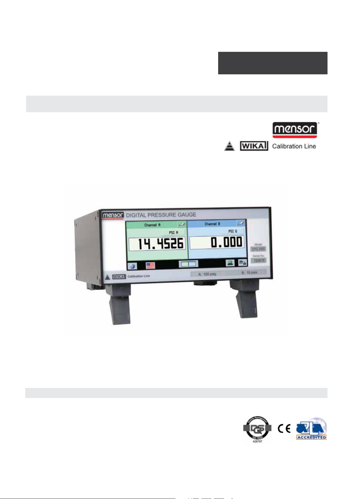
Digital Pressure Gauge
SERIES CPG 2500
Operating Instructions
Digital Pressure Gauge Series CPG 2500 PN 0017851001 F
Page 2
Digital Pressure Gauge
SERIES CPG 2500
This Warning symbol indicates that danger of injury for
persons and the environment and/or considerable damage
!
Warning
!
Caution
(mortal danger, danger of injury) will occur if the respective
safety precautions are not taken.
This Caution symbol indicates danger for the system and
material if the respective safety precautions are not taken.
i
Notice
This Notice symbol does not indicate safety notices but
information for a better understanding of the facts.
2 Mensor/WIKA Operating Instructions Series CPG 2500
Page 3

Digital Pressure Gauge
SERIES CPG 2500
Table of Contents
1. General Information 7
1.1 Warranty 7
1.2 Important Notice 7
1.3 FCC Radio Frequency Emission Notice 8
1.4 Trademarks and Copyrights 8
1.5 Software License Agreement 8
1.6 Mensor Service Plus 9
1.6.1 After the Warranty 9
1.6.2 Calibration Services 9
1.6.3 Accreditations 9
1.7 Packaging for Shipment 9
2. Safety Notices 10
2.1 User Responsibiliities 10
2.2 General Safety Notices 10
2.1 Warnings and Caution Notices 11
3. Product Description 13
3.1 General Description 13
3.2 Features 13
3.3 Front Panel 14
3.4 Display 14
3.5 Chassis Assembly 15
3.6 Turning on the CPG 2500 15
4. Specifications 17
5. Installation 19
5.1 Unpacking the Instrument 19
5.2 Dimensions 19
5.3 Mounting 19
5.4 Rear Panel 20
5.5 Pressure Connections 20
5.5.1 Pressure Port 21
5.5.3 Remote Bus Connections 21
Mensor/WIKA Operating Instructions Series CPG 2500 3
Page 4

Digital Pressure Gauge
SERIES CPG 2500
5.6 Power Up 21
6. Local Operation 23
6.1 General Operation 23
6.2 Keys and Tabs 23
6.3 Display Screen Features 23
6.4 Tool Bar 24
6.4.1 Contact and Version Information Key 24
6.4.2 Language selection Key 24
6.4.3 Main screen view Key 25
6.4.4 Remote setup Key 26
6.4.5 Remote status Key 26
6.5 Channel Frames 26
6.5.1 Presure reading window 26
6.5.2 Channel setup Key 26
6.5.2.1 Display Tab 27
6.5.2.1.1 Adjust Function 27
6.5.2.1.2 Measure Function 27
6.5.2.2 Sensor Tab 28
6.5.2.2.1 Standard Pressure Display Mode 28
6.5.2.2.2 Delta Pressure Display Mode 29
6.5.2.2.2.1 Display Tab (Delta) 29
6.5.2.2.2.2 Sensor Tab (Delta) 30
6.5.2.2.2.3 Adjust Tab (Delta) 30
6.5.2.2.2.4 Data Tab (Delta) 30
6.5.2.3 Adjust Tab 31
6.5.2.3.1 Zero 31
6.5.2.3.2 Head Correction 31
6.5.2.4 Data Tab 32
6.5.3 Pressure Units Key 33
6.5.3.1 English Tab 33
6.5.3.2 Metric Tab 34
6.5.3.3 User units Tab 34
4 Mensor/WIKA Operating Instructions Series CPG 2500
Page 5

Digital Pressure Gauge
SERIES CPG 2500
7. Remote Operation 35
7.1 Remote Setup 35
7.1.1 Instrument Tab 35
7.1.1.1 Emulation Mode 35
7.1.1.2 Channel 35
7.1.2 Ethernet Tab 36
7.1.3 Serial Tab 37
7.1.3.1 Cable Requirements 37
7.1.3.2 Command and Query Format 38
7.1.3.3 Command Set Definitions 38
7.1.3.4 Output Formats 39
7.1.3.5 Commands and Queries 39
7.1.3.6 Units Command Syntax 44
7.1.3.7 CPG 2500 Error Codes 45
7.1.3.8 Remote Emulation 46
7.1.3.8.1 DPG 2100 Emulated Commands and Queries 46
7.1.3.8.2 Units Command Syntax for DPG 2100 Measurement Units 52
7.1.3.8.3 DPG II Models 14000/15000 Terse Message Set Emulation 54
7.1.3.8.4 General SCPI WIKA Commands 58
7.1.3.8.4.1 Error Messages and Error Codes 60
7.1.4 IEEE-Tab (option) 61
7.1.4.1 GPIB Capability Codes 61
7.1.4.2 Interface Functions 62
7.1.4.3 IEEE-488.2 Commands 62
8. Options 63
8.1 Barometric Reference Transducer 63
8.1.1 Gauge Pressure Emulation 63
8.1.2 Absolute Pressure Emulation 63
8.1.3 Calibration 64
8.1.4 Specifications 64
8.2 Barometer 64
8.2.1 Zero and Sea Level Adjustment 64
8.2.2 Calibration 66
Mensor/WIKA Operating Instructions Series CPG 2500 5
Page 6

Digital Pressure Gauge
SERIES CPG 2500
8.2.3 Specifications 66
8.3 Analog Output 66
8.3.1 Command Set for Analog Output Option 67
8.3.2 Zero and Span Adjustment 68
8.3.3 Specifications 69
8.4 IEEE-488 (GPIB) (see 7.1.4) 70
8.5 Rack Mount Kit (optional accessory) 70
9. Maintenance 71
9.1 Beyond the Warranty 71
9.2 Spare Parts 72
9.3 Replacing the fuse 72
10. Calibration 73
10.1 Environment 73
10.2 Pressure Standards 73
10.3 Calibration Medium 73
10.4 Setup 74
10.5 Calibration Process 75
10.5.1 Sensor Tab 76
10.5.2 Utility Tab 76
10.5.2.1 Zero and Head Correction 76
10.5.2.2 Restore Factory Cal 77
10.5.2.3 Change Password 77
10.5.2.4 Date of Calibration 77
10.5.3 Edit Tab 78
10.5.4 Calibrate Tab 78
10.5.4.1 Procedure 1: ‘As found’ Data 79
10.5.4.2 Procedure 2: Active Calibration 79
11. Appendix 81
11.1 Measurement Units 81
11.2 Conversion Factors, psi 82
11.3 Conversion Factors, millitorr 84
11.4 Conversion Factors, pascal 85
6 Mensor/WIKA Operating Instructions Series CPG 2500
Page 7

Digital Pressure Gauge
SERIES CPG 2500
1. General Information
1.1 Warranty
All products manufactured by Mensor® Corporation (Mensor) are warranted to be free
of defects in workmanship and materials for a period of one year from the date of shipment. No other express warranty is given, and no affirmation of Seller, by words or actions, shall constitute a warranty. SELLER DISCLAIMS ANY IMPLIED WARRANTIES OF
MERCHANTABILITY OR FITNESS FOR ANY PARTICULAR PURPOSES WHATSOEVER.
If any defect in workmanship or material should develop under conditions of normal use
and service within the warranty period, repairs will be made at no charge to the original purchaser, upon delivery of the product(s) to the factory, shipping charges prepaid.
If inspection by Mensor or its authorized representative reveals that the product was
damaged by accident, alteration, misuse, abuse, faulty installation or other causes
beyond the control of Mensor, this warranty does not apply. The judgment of Mensor
will be final as to all matters concerning condition of the product, the cause and nature
of a defect, and the necessity or manner of repair. Service, repairs or disassembly of the
product in any manner, performed without specific factory permission, voids this warranty.
MENSOR MAKES NO WARRANTY OF ANY KIND WITH REGARD TO THIS MANUAL,
INCLUDING, BUT NOT LIMITED TO, THE IMPLIED WARRANTIES OF MERCHANTABILITY AND FITNESS FOR A PARTICULAR PURPOSE. Mensor shall not be liable for
errors contained herein or for incidental or consequential damages in connection with
the furnishing, performance, or use of this material.
1.2 Important Notice
The product specifications and other information contained in this manual are subject to
change without notice.
Mensor has made a concerted effort to provide complete and current information for
the proper use of the equipment. If there are questions regarding this manual or the
proper use of the equipment, contact Mensor at:
TEL 1.512.396.4200 WEB SITE www.mensor.com
TEL 1.800.984.4200 (U.S.A. only) E-MAIL sales@mensor.com
FAX 1.512.396.1820 tech.support@mensor.com
Copyright © 2005, Mensor Corporation. All rights reserved.
Mensor/WIKA Operating Instructions Series CPG 2500 7
Page 8

Digital Pressure Gauge
SERIES CPG 2500
1.3 FCC Radio Frequency Emission Notice
This equipment has been tested and found to comply with the limits for a Class A digital
device, pursuant to part 15 of the FCC Rules. These limits are designed to provide
reasonable protection against harmful interference when the equipment is operated in a
commercial environment. This equipment generates, uses, and can radiate radio frequency energy and, if not installed and used in accordance with the instruction manual,
may cause harmful interference to radio communications. Operation of this equipment
in a residential area is likely to cause harmful interference in which case the user will be
required to correct the interference at his or her own expense.
USE SHIELDED CABLES TO CONNECT EXTERNAL DEVICES TO THIS INSTRUMENT
TO MINIMIZE RF RADIATION.
1.4 Trademarks and Copyrights
Mensor is a registered trademark of Mensor Corporation. All other brand and product
names are trademarks or registered trademarks of their respective companies. ©2007,
Mensor Corporation. All rights reserved.
Korean font: Copyright (C) 1987, 1988; Daewoo Electronics Co., Ltd.
Chinese font: Copyright (C) 1988; The Institute of Software, Academia Sinica. Correspondence address: P.O. Box 8718, Beijing, China 100080.
1.5 Software License Agreement
This product contains intellectual property, i.e., software programs, that are licensed for
use by the end user/customer (hereinafter “end user”).
This is not a sale of such intellectual property.
The end user shall not copy, disassemble or reverse compile the software program.
The software programs are provided to the end user “as is”
without warranty of any kind, either express or implied, includ-
i
Notice
Mensor and its suppliers shall not be held to any liability for any damages suffered or
incurred by the end user (including, but not limited to, general, special, consequential
ing, but not limited to, warranties of merchantability and fitness
for a particular purpose. The entire risk of the quality and performance of the software program is with the end user.
8 Mensor/WIKA Operating Instructions Series CPG 2500
Page 9

Digital Pressure Gauge
SERIES CPG 2500
or incidental damages including damages for loss of business profits, business interruption, loss of business information and the like), arising from or in connection with the
delivery, use or performance of the software program.
1.6 Mensor Service Plus
If you have problems and you don’t find the answer in this manual, contact Mensor at
1.800.984.4200 (USA only) or 1.512.396.4200 for personal assistance, or at any of the
contact addresses listed on the rear cover of this manual. We are ready to help.
1.6.1 After the Warranty
Mensor’s concern with the performance of this instrument is not limited to the warranty
period. We provide complete repair, calibration and certification services after the warranty for a nominal fee.
1.6.2 Calibration Services
In addition to servicing our own products Mensor can perform a complete pressure
calibration service, up to 20,000 psi, for all of your pressure instruments. This service
includes an accredited calibration.
1.6.3 Accreditations
Mensor Corporation is registered to ISO 9001:2008. The calibration program at Mensor
is accredited by A2LA, as complying with both the ISO/IEC 17025:2005 and the ANSI/
NCSL Z540-1-1994 standards.
1.7 Packaging for Shipment
If the product must be shipped to a different location or returned to Mensor for any
reason through a common carrier it must be packaged properly to minimize the risk of
damage.
The recommended method of packing is to place the instrument in a container, surrounded on all sides with at least four inches of shock attenuation material such as
styrofoam peanuts.
Mensor/WIKA Operating Instructions Series CPG 2500 9
Page 10

Digital Pressure Gauge
SERIES CPG 2500
2. Safety Notices
2.1 User Responsibilities
To ensure safety, the user must make sure that:
• The system is used properly, no dangerous media are used and that all technical
specifications are observed.
• The system is operated in perfect operating condition.
• This operation manual is legible and accessible to the user at the system’s location.
• The system is operated, serviced and repaired only by authorized and qualified personnel.
• The operator receives instruction on industrial safety and environmental protection,
and is knowledgeable of the operating instructions and the safety notices contained
therein.
2.2. General Safety Notices
The system should only be operated by trained personnel who are
familiar with this manual and the operation of the instrument.
i
Notice
WARNING: A condition for trouble-free and safe operation of this
system is proper transport, proper storage, installation, assembly
!
Warning
and proper use as well as careful operation and maintenance.
Any operation not described in the following instructions should
be prohibited. The system must be handled with care required for
an electronic precision instrument (protect from humidity, impacts,
strong magnetic fields, static electricity and extreme temperatures).
Do not insert any objects into the instrument.
The system is powered via the power cable with a voltage that can
cause physical injury. Even after disconnecting the system from the
power supply, dangerous voltages can temporarily occur due to
capacitance.
Extreme care must be taken with pressure connections when using
hazardous or toxic media.
Repairs must only be performed by authorized service personnel.
10 Mensor/WIKA Operating Instructions Series CPG 2500
Page 11
Digital Pressure Gauge
SERIES CPG 2500
i
Notice
2.3 Warnings and Caution Notices
!
Warning
!
Warning
Additional safety notices are found throughout this manual.
WARNING: HIGH PRESSURE! High pressure gases are potentially
hazardous. Energy stored in these gases and liquids can be released
suddenly and with extreme force. High pressure systems should be
assembled and operated only by personnel who have been trained in
proper safety practices.
WARNING: NOT EXPLOSION PROOF! Installation of this instrument
in an area requiring devices rated as intrinsically safe is not recommended.
WARNING: POSSIBLE INJURY! The tubing, valves, and other appara-
!
Warning
!
Caution
Mensor/WIKA Operating Instructions Series CPG 2500 11
tus attached to the gauge must be adequate for the maximum pressure which will be applied, otherwise physical injury to the operator
or bystanders is possible.
CAUTION: USE THE PROPER PRESSURE MEDIUM! Use only clean,
dry, non-corrosive gases unless otherwise specified by mensor. This
instrument is not designed for oxygen use.
Page 12

Digital Pressure Gauge
SERIES CPG 2500
CAUTION: As with most sensitive electronic equipment, switch the
!
Caution
Additional Warning and Caution notices are found throughout this manual.
power switch off before connecting or disconnecting to a power
source to prevent data loss.
CAUTION: ESD PROTECTION REQUIRED. The proper use of grounded work surfaces and personal wrist straps are required when
coming into contact with exposed circuits (printed circuit boards) to
prevent static discharge to sensitive electronic components.
12 Mensor/WIKA Operating Instructions Series CPG 2500
Page 13
Digital Pressure Gauge
SERIES CPG 2500
3. Product Description
3.1 General Description
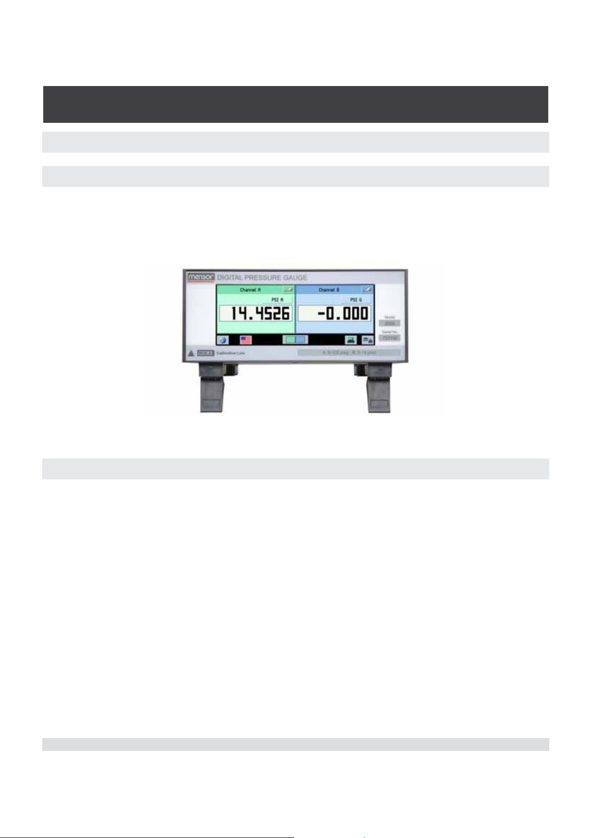
The CPG 2500 Digital Pressure Gauge is a multi-channel pressure system designed
to test and calibrate a variety of pressure devices in either absolute or gauge pressure
modes. The CPG 2500 can have two independent measurement channels plus an optional barometric reference.
Figure 3.1 - Front View
3.2 Features
Here is a short list of significant features designed into the CPG 2500:
1. Up to two highly stable, temperature compensated, pressure transducers.
2. An optional internal high accuracy barometric reference transducer provides gauge
pressure emulation for all of the absolute ranges and absolute pressure emulation for
gauge ranges.
3. A color HVGA display with a touch screen for intuitive operator interface.
4. Multiple languages; change the language for on-screen text and number/date for-
mats by simply touching one of the “national flag” icons available on the display. The
current language selections available are listed in Section 6, Local Operation, under
the heading “Language selection key”.
Operate the CPG 2500 while it is either sitting on a bench or mounted in a standard
equipment rack. Use either front panel input (Local Operation), or send commands and
queries over a bus from a separate “host” controller (Remote Operation).
Mensor/WIKA Operating Instructions Series CPG 2500 13
Page 14

Digital Pressure Gauge
SERIES CPG 2500
3.3 Front Panel
The CPG 2500 front panel includes a 6.2 inch color Half Video Graphics Array (HVGA)
liquid crystal display featuring touch screen technology. Operator input is accomplished
by pressing the words or icons presented on the display. There are no discrete keypads
or switches on the front panel.
On the lower right hand side of the front panel there are labels which show the model
number, serial number, and calibrated pressure ranges of the internal transducers.
3.4 Display
When the CPG 2500 is powered up it takes about one minute to initialize, then displays
a screen similar to the one shown in “6.3 - Display Screen Features”. The display is
made up of rectangles that display text or icons.
Keys, Tabs, Labels and Windows: In this manual a key is a small rectangle which
acts as a switch when pressed. Keys have borders with a three dimensional, shadowed
effect. Tabs are a group of touch points, each of which will overlay most of the screen
with one page related to its title subject. Small rectangles with double line borders that
display information, but do not respond to being touched, are called Labels or Windows.
Keys cause something to change when they are touched. Each key has a characteristic response when actuated; either an instant, single step response when the key is
pressed, or a delayed response when released. Operators will quickly become accustomed to the particular characteristics of the frequently used keys. Some keys become
labels under certain conditions, then resume their key function in other circumstances.
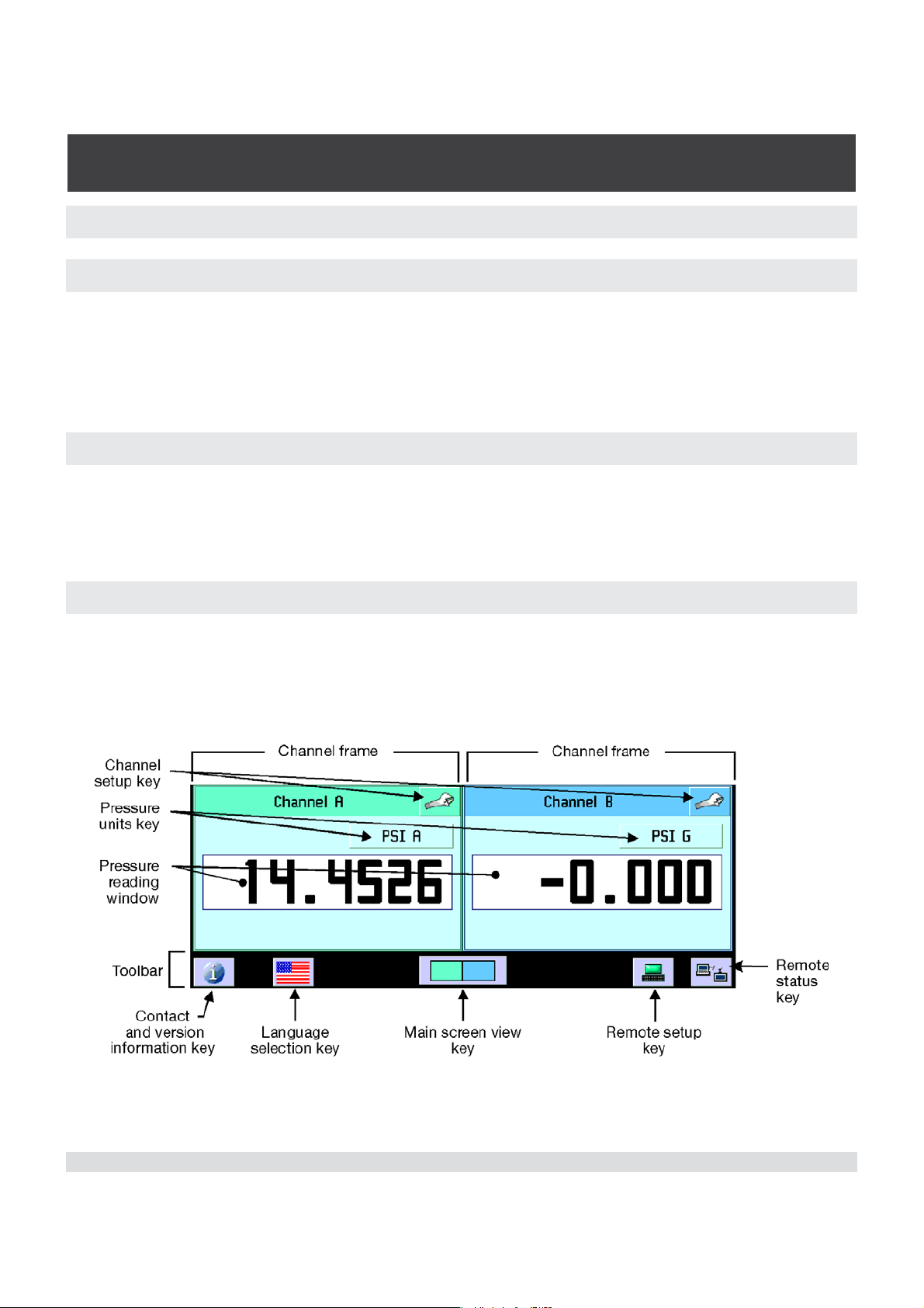
Main Screen: The main screen appears after power-up. This screen contains the channel frames and toolbar.
Channel Frame(s): The channel frames contain information specific to a channel. The
channel frames are color coded with channel A being green and channel B being blue.
The Delta channel is yellow. If only one channel is installed, a wide frame will be displayed in the color of the channel selected. The channel frame contains the channel
setup key (wrench icon), the channel title bar, the calibration function key (if enabled),
the engineering units key, the pressure reading window, and the display function windows/keys (if enabled).
Toolbar Keys: The toolbar at the bottom of the screen has the Contacts and Version
Information key (brings up a corporate information display), the language selection key,
the main screen view key, the remote setup key, and the remote status key.
14 Mensor/WIKA Operating Instructions Series CPG 2500
Page 15
Digital Pressure Gauge
SERIES CPG 2500
3.5 Chassis Assembly
The chassis assembly acts as the housing for the system. The system has no userserviceable parts except for the fuse, and therefore the chassis should not be opened
except by qualified repair personnel at Mensor or certified service locations for any
other reason.
3.6 Turning on the CPG 2500
You can confirm that your CPG 2500 is operational right now. Apply power to the power
connector on the rear of the instrument with the included power adapter, remove any
plastic plugs from the rear panel pressure ports, and press the power switch to ON. The
system will go through an initialization process and then a display will appear similar to
the screen shown below.
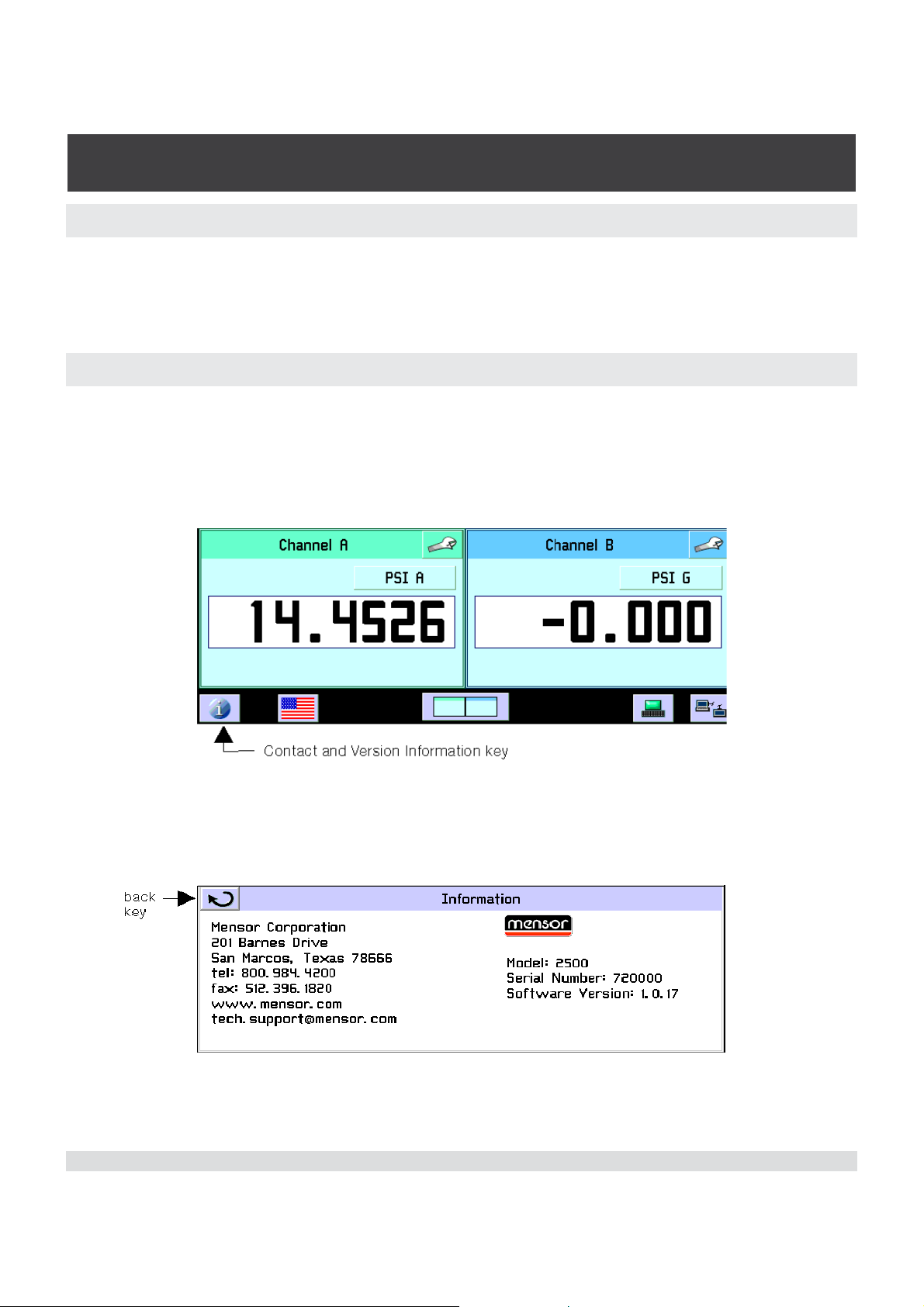
Touch the Contact and Version Information key on the toolbar and a window will appear
listing the Mensor customer service contact and software version information. Press the
back key to return to the main screen.
Mensor/WIKA Operating Instructions Series CPG 2500 15
Page 16

Digital Pressure Gauge
SERIES CPG 2500
NOTES
16 Mensor/WIKA Operating Instructions Series CPG 2500
Page 17
Digital Pressure Gauge
SERIES CPG 2500
4. Specifications
Accuracy specifications presented herein are obtained by comparison with primary
standards traceable to the National Institute of Standards and Technology (NIST). These
specifications are obtained in accordance with the ISO Guide to the Expression of
Uncertainty in Measurement (GUM). The calibration program at Mensor is accredited
by the American Association of Laboratory Accreditation (A2LA) as complying with both
the ISO/IEC 17025:2005 and the ANSI/NCSL Z540-1-1994 standards. If there is an
exception to the requirements and recommendations of Z540 during a calibration the
exception is noted on the individual calibration certificate.
Mensor reserves the right to change specifications without notice.
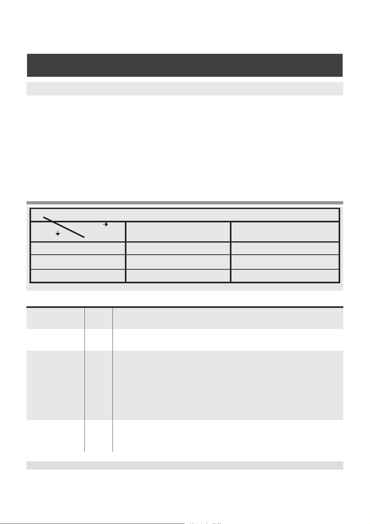
This table shows available ranges in psi corresponding to the mode and total uncertainty.
Total
Mode
Gauge
Bi Directional
Absolute
*0.01% IntelliScale-50 (0.01% IS-50) is defined as a total uncertainty of 0.005% of full scale (FS) from 0% to 50% of FS
and 0.01% of reading from 50% to 100% of FS.
Compensated
Uncertainty
°C 15 ... 45
0.01% FS 0.01% IS-50*
0...36 to 0...10,000 0...15 to 0...6,000
-0.18 ... 0.18 to -15 to 10,000 Not available
0...5 to 0...10,000 0...15 to 0...6,000
temp range
Calibration
days 180
interval
Pressure
units
psi, inHg @ 0°C and 60°F, inH
@ 4°C, 20°C and 60°F, mTorr, inSW @ 0°C, ftSW @ 0°C, ATM,
bar, mbar, mmH
O @ 4°C, cm H2O @ 4°C, MH2O @ 4°C,
2
mmHg @ 0°C, cmHg @ 0°C, Torr, kPa, Pa, Dy/cm
2
cm
, mSW @ 0°C, OSI, PSF, TSF, TSI, μHg @ 0°C, hPa, mPa,
mmH
0 20°C, cmH2O 20°C, MH2O 20°C. All seawater units
2
O @ 4°C, 20°C and 60°F, ftH2O
2
2
, g/cm2, kg/
are 3.5% salinity.
Pneumatic
interfaces
To 6000 psi: 7/16 - 20 female SAE/MS. 1/8” FNPT adapters
provided. Ranges >6000 psi: Autoclave F250C/HIP HF4.
6IJIVIRGITSVXWXERHEVH TWM*7STXMSREPTWM*7
Mensor/WIKA Operating Instructions Series CPG 2500 17
Page 18

Digital Pressure Gauge
SERIES CPG 2500
Pressure
media
Clean, dry, non-corrosive, non-conbustible, non-oxidizing
gases. Not suitable for oxygen use
Display 6.2” color LCD with 4 wire resistive touch screen
Resolution digits 6 significant digits (up to 1 ppm); user selectable.
Warmup time min Approximately 15 minutes to achieve full accuracy depending
on environment.
Remote user
interfaces
Power input
requirements
Operating
temp range
Storage
temp range
Orientation
°C 0° ... 50
°C 0° ... 70.
Standard: RS-232 and Ethernet
Optional: IEEE-488 and Analog Output
+5 VDC, 3 A min.
Fuses: Littelfuse® 0454 002
Note: This is not the compensated temperature range.
Minimal vibration. Non-condensing humidity.
Negligible, can be removed with re-zeroing.
effects
Weight lbs. <5
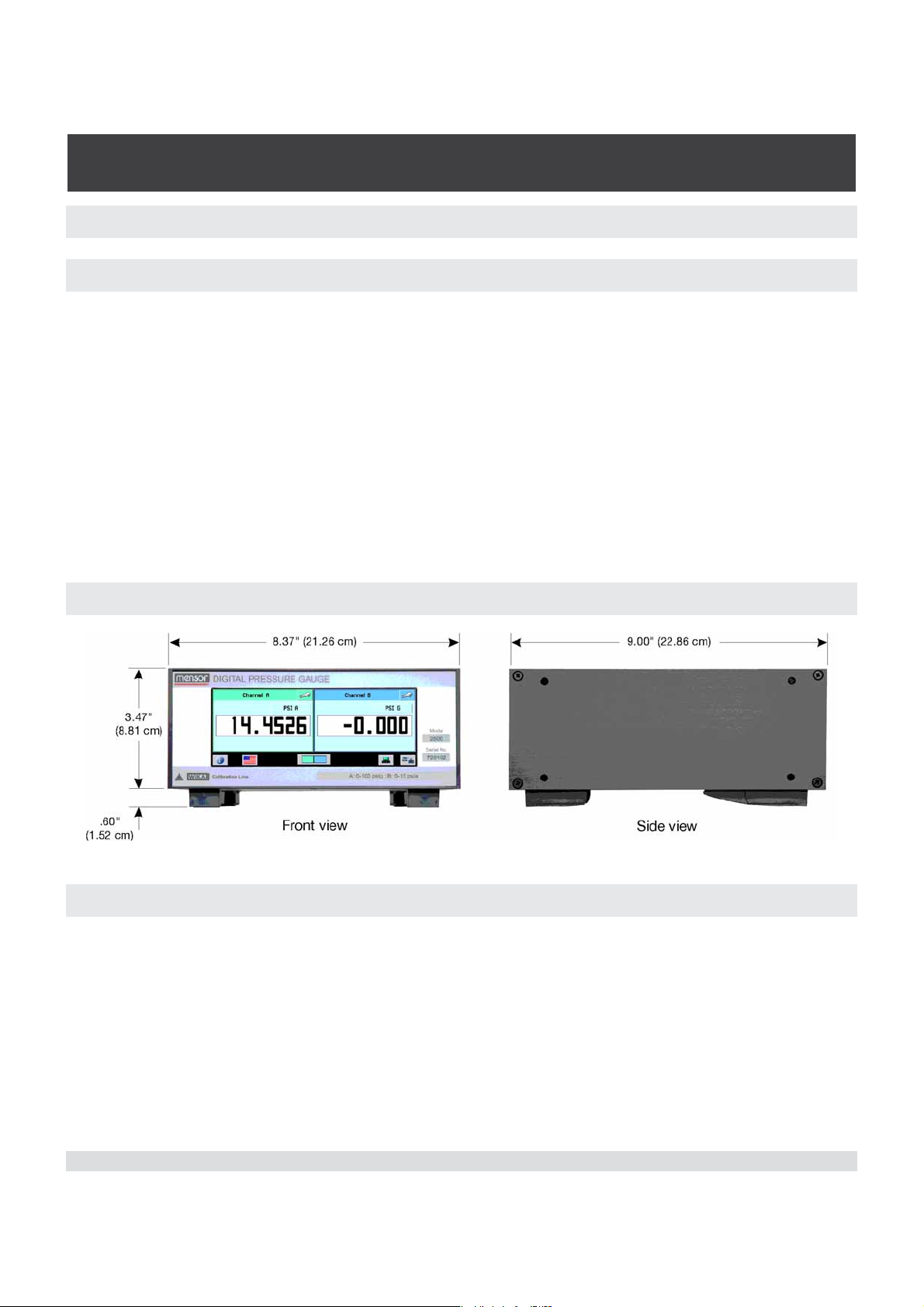
Dimensions in.
(cm)
8.37” wide x 3.47” high x 9.00” deep (21.26 cm x 8.81 cm x
22.86 cm).
Half rack width x 2U x 9” deep.
Feet: .96 wide x .60” high x 3.10” deep (2.44 cm x 1.52 cm x
7.87 cm).
Compliance The CPG 2500 is compliant to:
EN 61326-1:1997
EN 61326-1:A1:1998
EN 61326-1:A2:2000
EN 61000-3-2:2000
EN 61000-3-3:1995
Reading rate 50ms, 20 readings per second
Operating
5 to 95% RH non-condensing
environment
Options Optional Output: Barometric Reference Transducer, Barom-
eter, IEEE-488 GPIB Interface, Analog Output.
Optional Accessories: Rack Mount Kit
18 Mensor/WIKA Operating Instructions Series CPG 2500
Page 19
Digital Pressure Gauge
SERIES CPG 2500
5. Installation
5.1 Unpacking the Instrument
In addition to functional testing, each unit is inspected for appearance prior to leaving
the factory. Upon receipt, please examine the transducer for shipping damage. Report
any apparent damage to the carrier immediately.
In addition to this manual you should have:
• CPG 2500 Digital Pressure Gauge;
• Power Supply;
• 1/8 inch FNPT fitting adapters;
• Any accessories ordered;
• An envelope containing the Calibration Certificate.
5.2 Dimensions
5.3 Mounting
The instrument can be set up on a table top or it can be rack-mounted. Rack mount
adapters are optional on the CPG 2500 (see Section 8, Options).
The special sensors used in the CPG 2500 are relatively insensitive to tilt and vibration.
However to further assure stability and accuracy, avoid mounting the instrument on
surfaces subject to excessive motor or machinery vibration.
Mensor/WIKA Operating Instructions Series CPG 2500 19
Page 20
Digital Pressure Gauge
SERIES CPG 2500
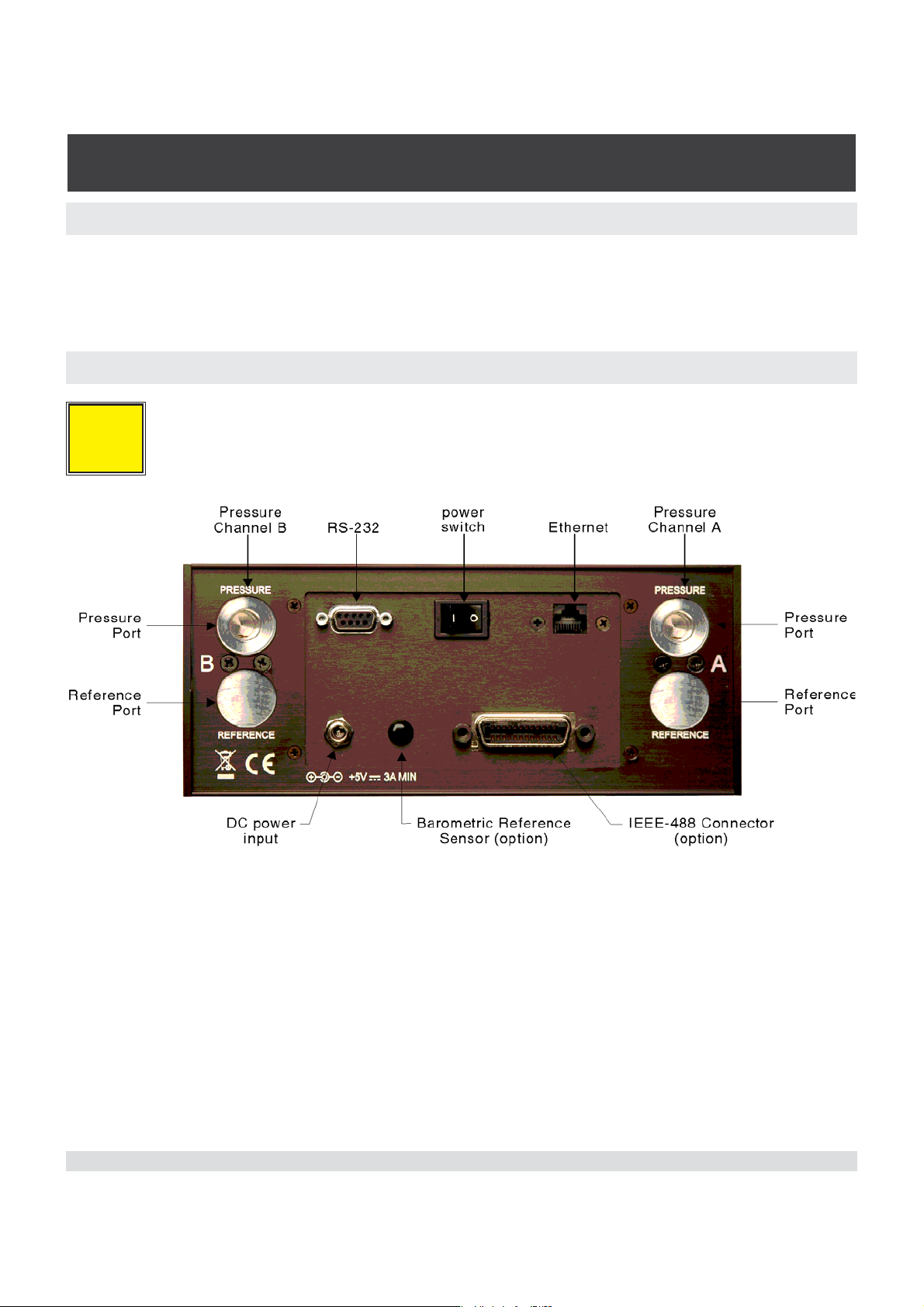
5.4 Rear Panel
Up to five pneumatic pressure ports are located on the rear panel. Positioned between
the pressure ports are the ethernet and RS-232 connectors and the power switch. Optional connectors could be a GPIB connector, a barometric reference hose barb, or an
analog output connector.
5.5 Pressure Connections
When making up a connection to an o-ring adapter fitting port use a
back-up wrench to prevent over-stressing the threads in the mani-
i
Notice
fold block.
All of the primary pressure ports on the rear are female 7/16 - 20 SAE/MS straight
threads per MS16142 and SAE J514 table 14. They require a tube fitting boss seal with
an o-ring per MS33656. Mensor provides female 1/8” NPT adapter fittings with the
instrument. The pressure connections can be made to these adapters with the proper
mating hardware. We recommend the use of either Loctite® Hydraulic Sealant or new
teflon tape on the threads of any male pipe fitting. Do not use sealant on fittings sealed
with an o-ring. The integrity of each seal is particularly important since even microscopic leaks can cause errors in pressure measurements.
20 Mensor/WIKA Operating Instructions Series CPG 2500
Page 21

Digital Pressure Gauge
SERIES CPG 2500
5.5.1 Pressure Port
Connect a device to be tested to the PRESSURE port. The CPG 2500 will precisely
measure the pressure at this port up to the full scale range of the sensor.
5.5.2 Reference Port
On low pressure (< 20 psi) gauge units this port is available to connect to the reference
side of the transducer. The maximum value is equal to or less than the range of the
sensor or 20 psi, whichever is less. This port is normally left open to atmosphere but
may be connected to a stable reference pressure. It is optionally available on all gauge
ranges <= 6000 psi.
5.5.3 Remote Bus Connections
See Section 7, Remote Operation, for connections and commands for operation over
the Ethernet or RS-232 serial port.
5.6 Power Up
After the pressure connections are secure, apply power to the power connector on the
rear of the instrument and switch the power switch ON. The instrument will go through
an initialization process and system check. As soon as the system check is completed
the system will default to a screen similar to the one shown in Section 6.3 - Display
Screen Features. Allow at least 15 minutes of warm up before performing critical pressure measurements.
Mensor/WIKA Operating Instructions Series CPG 2500 21
Page 22

Digital Pressure Gauge
SERIES CPG 2500
NOTES
22 Mensor/WIKA Operating Instructions Series CPG 2500
Page 23
Digital Pressure Gauge
SERIES CPG 2500
6. Local Operation
6.1 General Operation
This section describes the procedures for operating the CPG 2500 from the front panel.
Instructions for operating the device remotely from an external computer are covered in
Section 7, Remote Operation. By following the procedures provided in these two sections and Section 10, Calibration, you can expect your CPG 2500 to deliver maximum
accuracy and dependability for many years of useful service.
6.2 Keys and Tabs
Local operation is accomplished by observing the data presented in the display, then
pressing the on-screen key or tab for the desired function. The back key is in the upper
left corner of all screens except for the main screen. It is used to return to the previous
screen.
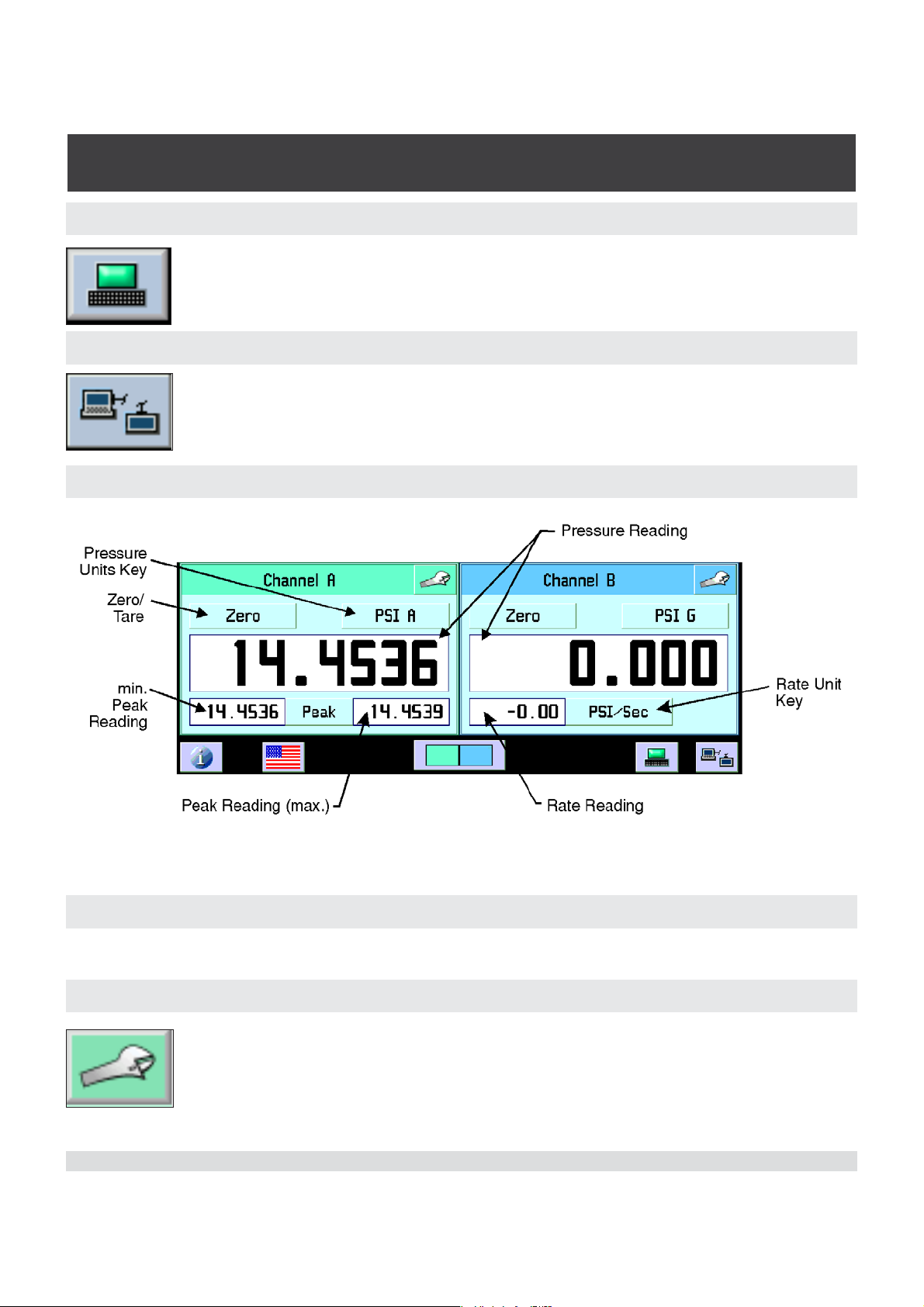
6.3 Display Screen Features
The screen shown below provides a brief description of the features shown on a dual
channel display after initialization. Additional keys will appear on this screen if activated
(zero, tare, peak and rate). All of the CPG 2500 screen features are described in more
detail throughout this manual.
Figure 6.3 - Display Screen Features
Mensor/WIKA Operating Instructions Series CPG 2500 23
Page 24
Digital Pressure Gauge
SERIES CPG 2500
6.4 Toolbar
6.4.1 Contact and Version Information Key
Press this key to display Mensor contact, instrument and software
version information.
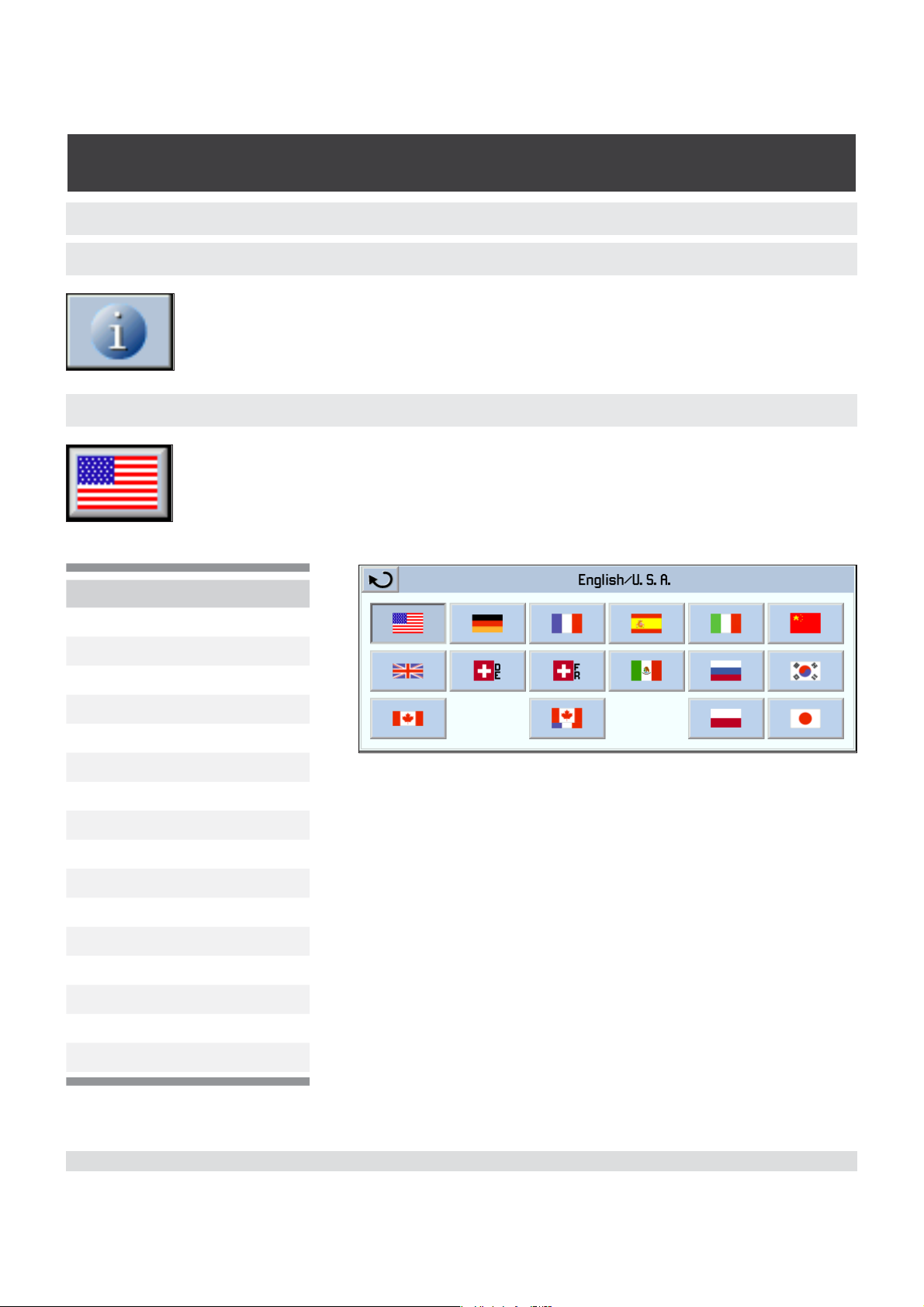
6.4.2 Language Selection Key
The flag icon on the toolbar is a key that indicates the language used in
all screens. Press this key to select the language used for local operation. The current language selections available are:
Language Country
English
German Germany
French France
Spanish Spain
Italian Italy
Chinese China
English Great Britain
German Switzerland
French Switzerland
Spanish Mexico
Russian Russia
Korean Korea
English Canada
French Canada
Polish Poland
Japanese Japan
USA
24 Mensor/WIKA Operating Instructions Series CPG 2500
Page 25
Digital Pressure Gauge
SERIES CPG 2500
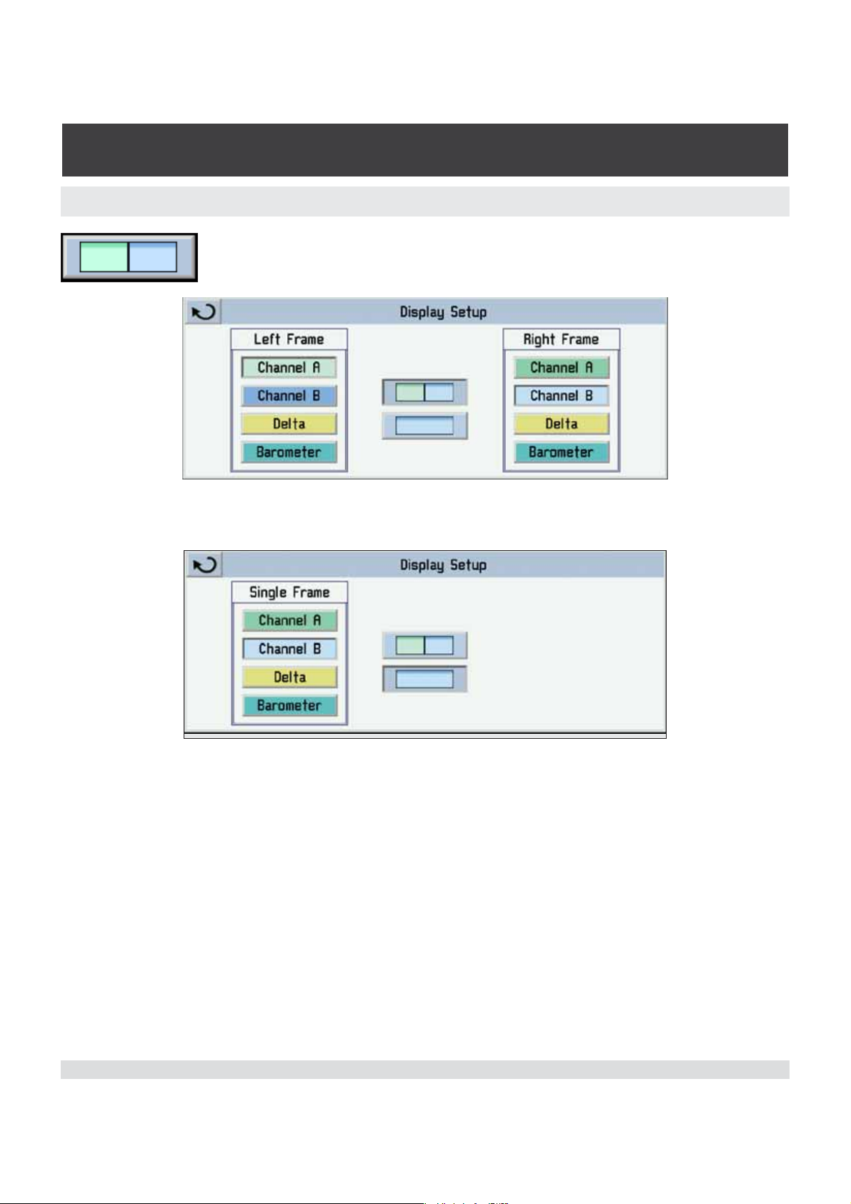
6.4.3 Main Screen View Key
Press this key to configure the channel displayed on the main
screen.
Select a channel to display on the left and right frames or press the single channel
display key in the middle to select a single channel.
To return to a dual channel display screen press the dual channel display key, select the
desired channels and return to the main screen by pressing the back key.
Mensor/WIKA Operating Instructions Series CPG 2500 25
Page 26
Digital Pressure Gauge
SERIES CPG 2500
6.4.4 Remote Setup Key
Press this key to set the operating parameters for Instrument emulation,
Ethernet, Serial RS-232 or optional IEEE-488. For further information see
Section 7, Remote Operation.
6.4.5 Remote Status Key
Press this key to view the remote communications monitor. The remote
monitor displays detailed information that is helpful to troubleshoot
programs.
6.5 Channel Frames
6.5.1 Pressure Reading window
This window always displays the current pressure reading.
6.5.2 Channel Setup Key
Press this key to access setup functions for a channel. The channel
setup screen has four tabs that group related types of settings.
26 Mensor/WIKA Operating Instructions Series CPG 2500
Page 27
Digital Pressure Gauge
SERIES CPG 2500
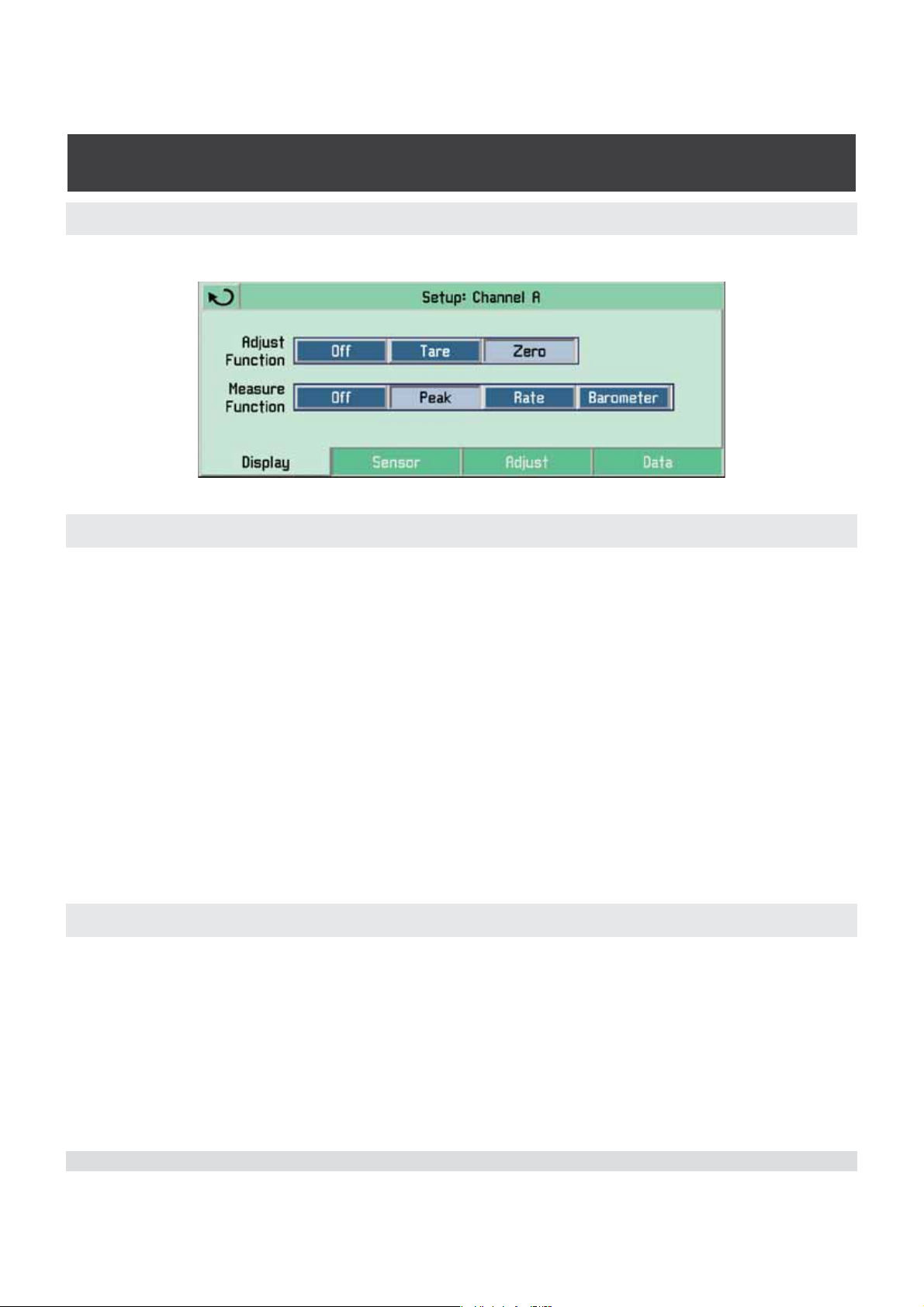
6.5.2.1 Display Tab
Press the display tab to configure the measure and adjust functions.
6.5.2.1.1 Adjust Function
The adjust function will add a Tare or Zero key on the upper left above the pressure
reading window. If these features are not desired, select Off.
Tare: Allows the user to temporarily set the measured pressure reading to zero. Press
the key again to return the reading to the true pressure.
Non-Password Protected Zero: Allows the user to zero the measured pressure reading. On gauge transducers, vent the pressure port to atmosphere and press the Zero
key. When the Zero key is pressed on an absolute sensor, a number entry keypad is displayed to allow the user to enter the applied pressure. When power is cycled the zero is
saved in the sensor through the password protected zero function (see Section 6.5.2.3 -
Adjust Tab). It will also return to the most recent factory calibrated zero when the “Reset
Factory Cal, OK” key is pressed (see Section 10.5.2 - Utility Tab). This feature must be
enabled in the Adjust settings to be available. See Section 6.5.2.3 - Adjust Tab for more
information.
6.5.2.1.2 Measure Function
The measure function will add peak, rate or the optional barometric sensor reading below the pressure reading window. If these features are not desired, select Off.
Peak: Displays the highest and lowest pressure points since the last reset or power up.
Rate: Reports the rate at which the measured pressure is changing. Press the Rate Unit
key on the main menu screen to select among the four time scales: second, minute,
hour and three hours.
Mensor/WIKA Operating Instructions Series CPG 2500 27
Page 28

Digital Pressure Gauge
SERIES CPG 2500
Barometer: If this optional feature was ordered with your CPG 2500, press Barometer
to display the atmospheric pressure reading.
6.5.2.2 Sensor Tab
6.5.2.2.1 Standard Pressure Display Mode
Press the sensor tab to select the pressure reading filter, the pressure measurement
type and resolution.
Filter: The Filter is an electronic filter to smooth out the pressure readings. Because of
differences in resolution, greater filtering may display a more stable reading for some
pressure units. Select the best filter for the current units.
Measure Type: If the Instrument is equipped with the optional barometric reference
sensor, the user can select Gauge or Absolute pressure emulation.
Resolution: The resolution key allows the user to select the number of significant digits
that will be displayed on the main screen.
28 Mensor/WIKA Operating Instructions Series CPG 2500
Page 29

Digital Pressure Gauge
SERIES CPG 2500
6.5.2.2.2 Delta Pressure Display Mode
This feature is available for a CPG 2500 when equipped with two primary sensors.
Delta Function: The delta function is selected from the Main Screen View (see Section
6.4.3).
To setup the delta function press the channel setup key from the delta
channel displayed. The delta setup screen will appear.
6.5.2.2.2.1 Display Tab (Delta)
The adjust and measure functions can be selected from this screen.
Mensor/WIKA Operating Instructions Series CPG 2500 29
Page 30

Digital Pressure Gauge
SERIES CPG 2500
6.5.2.2.2.2 Sensor Tab (Delta)
The delta function can be selected for a displayed channel, along with a different resolution.
6.5.2.2.2.3 Adjust Tab (Delta)
The adjust tab has no function in delta setup.
6.5.2.2.2.4 Data Tab (Delta)
The data tab resets the selected channel to default settings.
30 Mensor/WIKA Operating Instructions Series CPG 2500
Page 31

Digital Pressure Gauge
SERIES CPG 2500
6.5.2.3 Adjust Tab
This tab is for adjusting zero and head pressure correction and setting access to those
features. These features can be locked out by pressing the key icon. A password screen
will appear. Enter the correct password. Next select the utility tab. The padlocks can
then be toggled on or off.
6.5.2.3.1 Zero
Zero can be adjusted on this tab and the main screen view (if selected) when the padlock icon is unlocked. Press the Zero key to enter a zero pressure offset.
6.5.2.3.2 Head Correction
Head correction can be adjusted on this tab when the padlock icon is unlocked. Press
the Head Correction key to modify the head pressure correction settings.
Four parameters may be set to reflect conditions at the operator’s site. Press either
English or Metric units for entering head pressure correction information into the CPG
2500. Press the Head Correction key and the following screen will appear:
Mensor/WIKA Operating Instructions Series CPG 2500 31
Page 32

Digital Pressure Gauge
SERIES CPG 2500
i
Notice
Height: Enter the difference in height between the center of the measure/control port of
the CPG 2500 and the reference level of the Device Under Test (DUT). If the reference
level of the DUT is lower than the center of the measure/control port of the CPG 2500,
enter a positive height. If it is higher, enter a negative height.
Gas Density: If nitrogen (N2) or dry air are being used as a pressure media, press the
appropriate selection. If another gas is being used, enter the density for the gas at standard pressure and temperature in either lb/cubic foot (english) or kg/liter (metric) units.
Gas Temperature: Enter the average gas temperature in degrees F or C. If unsure of
the gas temperature use 68 F.
Local Gravity: Enter the local gravity acceleration value. If unsure, press the Standard
gravity key.
Limits:
Height ±1200 inches
Density 0 to 1 lb/cu ft
Temperature 0 to 120 °F
Gravity 32 to 32.4 ft/sec²
Head correction parameters are stored separately for each channel.
6.5.2.4 Data Tab
Press the data tab to display the sensor data.
32 Mensor/WIKA Operating Instructions Series CPG 2500
Page 33

Digital Pressure Gauge
SERIES CPG 2500
Sensor information is displayed showing the serial number, date of calibration, minimum
and maximum range, and the pressure units. If the Analog option is installed, the maximum and minimum values will be displayed.
Press the Default key to reset the instrument to the following conditions:
• Clear peak maximum and peak minimum values
• Set sensor filter to Normal
• Set resolution to six significant figures.
6.5.3 Pressure Units Key
Above the pressure reading window on the channel frame is the Units
key. Touch the key to select from tables of English, Metric and User
Defined Units. The current unit is shown selected. Touch any other
pressure unit key to select that unit. Press the back key to return to
the main screen. All the displayed pressure values for the channel will
change to the newly selected unit.
6.5.3.1 English Tab
Mensor/WIKA Operating Instructions Series CPG 2500 33
Page 34

Digital Pressure Gauge
SERIES CPG 2500
6.5.3.2 Metric Tab
6.5.3.3 User Units Tab
To enter customized user units, press the User Units tab. Choose PSI or pascal as a
base unit and then enter a scaling factor by pressing the number key. Select from these
two units by pressing User 1 or User 2.
34 Mensor/WIKA Operating Instructions Series CPG 2500
Page 35

Digital Pressure Gauge
SERIES CPG 2500
7. Remote Operation
Use the following screens to set the operating parameters for Instrument emulation,
Ethernet, Serial (RS-232) and IEEE-488 (GPIB) information.
7.1 Remote Setup
Press the Remote Setup key (computer icon) on the toolbar to configure
remote communication parameters for the CPG 2500.
7.1.1 Instrument Tab
Press the Instrument tab to set the remote communication emulation mode and for
channel selection.
7.1.1.1 Emulation Mode
Mensor: The default command set is Mensor.
2100: The DPG 2100 remote emulation commands and queries information are listed
under the heading ‘Remote Emulation’ in this section.
SCPI WIKA: The SCPI WIKA mode emulates the WIKA command set in SCPI format.
7.1.1.2 Channel
Press this key to select the active remote channel as A or B. This feature is useful for
customers replacing two single channel instruments with a dual channel CPG 2500. The
user selects the channel to be active during remote communications.
Mensor/WIKA Operating Instructions Series CPG 2500 35
Page 36

Digital Pressure Gauge
SERIES CPG 2500
7.1.2 Ethernet Tab
Press the Ethernet tab to set up the Ethernet parameters.
!
Caution
!
Caution
The Ethernet communication port allows the CPG 2500 to communicate with computers using 10/100Based-T specifications.
Connecting directly to a PC requires a crossover Ethernet cable. Hub or router connection requires a straight Ethernet cable.
Before using Ethernet communication, four parameters must be set up: IP, Netmask,
Gateway, and Port.
CAUTION: Please contact your network administrator for
proper settings.
CAUTION: Please consult your computer resources department
prior to connecting this instrument to your network to verify there
are no conflicts with existing IP addresses.
36 Mensor/WIKA Operating Instructions Series CPG 2500
Page 37

Digital Pressure Gauge
SERIES CPG 2500
7.1.3 Serial Tab
Press this tab to set up the serial port parameters. The serial communication port allows
the CPG 2500 to communicate in RS-232 format with computers, terminals, PDAs, or
similar hosts.
These parameters should be set to match your host computer. Default settings are:
57600 baud, 8 data bits, 1 stop bit, no parity, and no echo.
If the echo checkbox is checked, the CPG 2500 will immediately echo back characters
sent over the serial port.
7.1.3.1 Cable Requirements
RS-232 communications are transmitted over a three conductor, shielded cable terminated in a standard DB9 connector on the instrument end, and a different gender connector on the host end. The proper pin-outs are shown in the following illustration.
CAUTION: When replacing an existing DPG 2100, the serial cable
should be replaced with a straight cable or a null-modem inserted in
!
Caution
the line.
Mensor/WIKA Operating Instructions Series CPG 2500 37
Page 38

Digital Pressure Gauge
SERIES CPG 2500
7.1.3.2 Command and Query Format
Commands must be sent in ASCII format and terminated with either a carriage return
(<cr>), linefeed (<lf>), or both. Commands are not case sensitive. Each query returns a
response. If an error is detected the response will include an error flag.
Command or Query field: Unless otherwise specified, commands are typically converted to queries by appending a question mark to the command. Table 7.1.3.5 lists all
of the CPG 2500 command or query keywords.
Data field: The data field is either in ASCII {string} or numeric {value} form. In the case
of multiple data fields, commas are required to separate the fields. Queries do not have
a data field. String (text) or value (numeric) data are acceptable in any of the following
formats:
Examples of {string} data: ON, OFF, mBar, inHg
Examples of {value} data: 1, 1.0, -5.678, 25.68324e-5
7.1.3.3 Command Set Definitions
In this manual a data entry made up of alpha characters is defined as a string, as opposed to data containing only numbers, such as “Enter 1 for ON or 0 for OFF” where 1
and 0 are defined as values.
Command: Any command or query listed in Table 7.1.3.5. For commands that take
boolean data the following strings are acceptable:
01
False True
No Yes
Off On
Separator: Space (SP).
Data: ASCII representations of numbers, {value}, or alpha characters, {string}, data as
defined above. When sending code a literal variable replaces the brackets and the enclosed character(s) shown in the following examples.
Termination: Linefeed (LF) or carriage return (CR) is used to signal the end of a command statement. For IEEE-488.2 operation “EOI” is an acceptable alternative.
Always send commands in one of the following formats:
1. [Command] [Termination];
2. [Command] [Separator] [Data] [Termination];
38 Mensor/WIKA Operating Instructions Series CPG 2500
Page 39

Digital Pressure Gauge
SERIES CPG 2500
3. Queries are special instructions in the form: [Command?] [Termination] where the
question mark, “?”, immediately precedes the terminator.
When a valid query is received, the CPG 2500 will return {data} terminated by CR and
LF. Floating point data is returned in the current engineering units in exponential format.
7.1.3.4 Output Formats
Pressure readings are returned in exponential notation in a format according to the
OUTFORM command as follows. Outform applies to both pressure channels.
1. <sp> pressure value <cr><lf>
2. <sp> pressure, units number,STANDBY <cr><lf>
3. <sp> pressure, pressure rate <cr><lf>
4. <sp> pressure, minimum peak, maximum peak <cr><lf>
7.1.3.5 Commands and Queries
Table 7.1.3.5 lists all of the current CPG 2500 commands and queries.
Channel specific commands are sent to only the active channel.
i
Notice
Optional emulation modes are available in which a CPG 2500 can emulate remote functions of different brands of pressure gauges. Please contact Mensor for more details.
Command or
Query
? none Returns data per the current output form.
ACQUIRE? 15 char string.
ADDRESS 0-31 Sets the GPIB Address
See ‘CHAN’ command.
Table 7.1.3.5 - CPG 2500 Commands and Queries
Data Response/Function
This command is used when multiple
Example:
Acquire? Test_stand_1
Returns:
<sp>(yes or no),CCC...
CCC<cr><lf>
computers would like to control the instru-
ment. Yes if acquisition is successful. No if
instrument is being controlled with another
computer. CCC... = name of controlling
computer. See: RELEASE? and UNLOCK
ADDRESS? <sp> xx <cr><lf> Returns the GPIB Address.
Mensor/WIKA Operating Instructions Series CPG 2500 39
Page 40

Digital Pressure Gauge
SERIES CPG 2500
A? <sp>n.nnnnne+nn<cr><lf> Returns the A channel pressure reading.
AR? <sp>n.nnnnne+nn<cr><lf> Returns the A channel rate.
BARO? <sp>n.nnnnne+nn<cr><lf> Returns reading from barometric sensor
B? <sp>n.nnnnne+nn<cr><lf> Returns the B channel pressure reading.
BR? <sp>n.nnnnne+nn<cr><lf> Returns the B channel rate.
CALDISABLE yes,no Sets whether or not calibration of the ac-
tive channel is disabled.
CALDISABLE? <sp>(yes or no)<cr><lf> Returns whether or not calibration of the
active channel is disabled.
CERR none Clears the error queue.
CHAN A or B Sets the active channel on the instrument.
CHAN? <sp>A or B or D or
Baro<cr><lf>
CHAN D none Sets the active channel to the Delta chan-
CHANFUNC Press, peak, rate, baro Sets the alternate function mode of the
CHANFUNC? <sp>CCCCC…<cr><lf> Returns the alternate function mode of the
DECPT? <sp>n<c><lf> Returns the number of decimal points for
DEFAULT none Sets the default values.
DELTAFUNC A-B none Sets the delta to be the result of the chan-
DELTAFUNC B-A none Sets the delta to be the result of the chan-
DELTAFUNC A+B none Sets the delta to be the result of the chan-
Returns which channel is active.
nel.
active channel.
channel.
the active channel (see RESOLUTION).
nel A reading - channel B reading.
(Chan D must be in the active channel).
nel B reading - channel A reading.
(Chan D must be in the active channel).
nel A reading + channel B reading.
(Chan D must be in the active channel).
DELTAFUNC? <sp>{A-B or B-A}<cr><lf> Returns delta function as one of the above
options. (Chan D must be in the active
channel).
40 Mensor/WIKA Operating Instructions Series CPG 2500
Page 41

Digital Pressure Gauge
SERIES CPG 2500
DOC mm/dd/yyyy Sets the date of cal for the active channel.
DOC? <sp>mmddyy<cr><lf> Returns the date of cal for the active chan-
nel.
DOM? <sp>mm/dd/yyyy<cr><lf> Returns the date of manufacture.
FILTER Off, Low, Normal, High Sets the reading filter 0, 80%, 92%, 95%.
FILTER? <sp> (filter)<cr><lf> Returns the reading filter.
GASDENSITY Value in lb/cuft Sets the head pressure gas density.
GASDENSITY? <sp>n.nnnnne+nn<cr><lf> Gets the head pressure gas density.
GASTEMP Value in degrees F Sets the head pressure gas temperature.
GASTEMP? <sp>n.nnnnne+nn<cr><lf> Gets the head pressure gas temperature.
GATEWAY nnn.nnn.nnn.nnn Sets the Ethernet gateway address.
GATEWAY? <sp>nnn.nnn.nnn.nnn
<cr><lf>
HEIGHT Value in inches Sets the head pressure height.
HEIGHT? <sp>n.nnnnne+nn<cr><lf> Gets the head pressure height.
ID? <sp> MENSOR, 2500,
ssssss,v.v.vv
IP nnn.nnn.nnn.nnn Sets the IP address of the instrument.
IP? <sp>nnn.nnn.nnn.nnn
<cr><lf>
KEYLOCK yes or no Locks or unlocks keyboard.
KEYLOCK? <sp>(yes or no)<cr><lf> Returns yes or no.
LISTRANGE? PRI,1, min,max Returns the range of the installed sensor
LOCALGRAVITY value in ft/s^2 Sets the local gravity in feet/sec^2.
LOCALGRAVITY? <sp>n.nnnnne+nn<cr><lf> Returns the local gravity in feet/sec^2.
NETMASK nn.nnn.nnn.nnn Sets the Ethernet network mask.
NETMASK? <sp>nnn.nnn.nnn.nnn
<cr><lf>
Gets the Ethernet gateway address.
Ssssss is the serial number, v.v.vv is the
CPG 2500 software version.
Returns the IP address of the instrument.
for the active channel.
Gets the Ethernet network mask.
OUTFORM 1 to 4 - (see Table 7.1.3.6) Sets the output format.
OUTFORM? <sp>X<cr><lf> Returns the output format (see 7.1.3.4).
Mensor/WIKA Operating Instructions Series CPG 2500 41
Page 42

Digital Pressure Gauge
SERIES CPG 2500
PEAKMAX? <sp>n.nnnnne+nn<cr><lf> Returns the maximum pressure since
peakreset was sent.
PEAKMIN? <sp>n.nnnnne+nn<cr><lf> Returns the minimum pressure since
peakreset was sent.
PEAKRESET none Resets the peak values.
PORT nnnnnn Sets the Ethernet port of the instrument.
PORT? <sp>nnnnn<cr><lf> Returns the Ethernet port of the instru-
ment.
PTYPE Absolute, Gauge or
Differential
PTYPE? <sp>CCCCC<cr><lf> Returns “Absolute” or “Gauge” for the
RANGEMAX? <sp>XXXXXXX<cr><lf> Returns the maximum range of the active
RANGEMIN? <sp>XXXXXXX<cr><lf> Returns the minimum range of the active
RATE? <sp>XXXXXXX<cr><lf> Returns the rate reading of the instrument
RDECPT? <sp>n<cr><lf> Returns the number of rate decimal points
RELEASE? 15 char string
Example:
Release? Test_stand_1
Returns: <sp>(yes or no),
CCC…CCC<cr><lf>
Sets the instrument pressure type - only
works if the optional barometric sensor is
installed.
pressure type.
transducer in the current units.
transducer in the current units.
in current units/second.
for the active channel. (see RESOLUTION)
This command is used to release control
of the instrument in a multiple computer
environment. Yes if release is successful.
No if instrument is being controlled with
another computer. CCC… = name of con-
trolling computer or AVAILABLE.
See: ACQUIRE? and UNLOCK
RESOLUTION n Sets the number of significant digits.
See DECPT?
RESOLUTION? <sp>n<cr><lf> Returns the number of significant digits.
See DECPT?
RFILTER value in % Sets the % of the rate filter.
RFILTER? <sp>n.nnnnne+nn<cr><lf> Returns the rate filter.
RWINDOW value in current units Sets rate exponential filter window.
42 Mensor/WIKA Operating Instructions Series CPG 2500
Page 43

Digital Pressure Gauge
SERIES CPG 2500
RWINDOW? <sp>n.nnnnne+nn<cr><lf> Returns rate exponential filter window.
SBAUD 9600, 19200, 38400, 57600 Sets the serial baud rate.
SBAUD? <sp>XXXX<cr><lf> Returns the serial baud data.
SCREENSRC A, B, or A,B, or B,A, or
Delta,A, or Delta,B
SCREENSRC? <sp>{A,B or A,Delta or
Delta,B}<cr><lf>
SDATA 7 or 8 Sets the serial data bits.
SDATA? <sp>X<cr><lf> Returns the serial data bits number.
SENSORID? <sp>Mensor QRS,SN
XXXXXX,VER V.VV
SPAN desired pressure or ? Sets span on active channel or for ?,
SPAN? <sp>XXXXXXX<cr><lf> Returns span scale factor for active chan-
SPARITY even, odd, none Sets the serial parity.
SPARITY? <sp>CCCC<cr><lf> Returns the serial parity.
SSTOP 1 or 2 Sets the serial stop bits.
SSTOP? <sp>X<cr><lf> Returns the serial stop bits.
Sets the CPG 2500 display mode.
Returns screen source as one of the
above options.
Returns the active sensor’s serial number
and firmware version.
clears previous value, must be >50% FS
and has a 1% limit.
nel.
UNITS units code or text in Table
7.1.3.6.
UNITS? <sp>CCCC<cr><lf> Returns the pressure units of the active
UNLOCK none Releases Acquire locks. See ACQUIRE?
WINDOW value in current units Sets the exponential filter window for the
WINDOW? <sp>n.nnnnne+nn<cr><lf> Returns the exponential filter window for
ZERO desired pressure or ? Sets zero to set pressure or for ?, clears
ZERO? <sp>xxxxxxx<cr><lf> Returns zero offset for active channel.
Mensor/WIKA Operating Instructions Series CPG 2500 43
Sets the engineering units for the active
channel.
channel in a text string.
and RELEASE?
active channel.
the active channel.
previous value.
Page 44

Digital Pressure Gauge
SERIES CPG 2500
7.1.3.6 Units Command Syntax for Measurement Units
Table 7.1.3.6 - UNITS Command Syntax for CPG 2500 Measurement Units
n Description Output Format Type
1 pounds per square inch PSI English
2 inches of mercury @ 0°C INHG English
3 inches of mercury @ 60°F INHG English
4 inches of water @ 4°C INH2O English
5 inches of water @ 20°C INH2O English
6 inches of water @ 60°F INH2O English
7 feet of water @ 4°C FTH2O English
8 feet of water @ 20°C FTH2O English
9 feet of water @ 60°F FTH2O English
10 millitorr MTORR Metric
11 inches of sea water @ 0°C INSW English
12 feet of sea water @ 0°C FTSW English
13 atmospheres ATM English
14 bars BAR Metric
15 millibars MBAR Metric
16 millimeters of water @ 4°C MMH2O Metric
17 centimeters of water @ 4°C CMH2O Metric
18 meters of water @ 4°C MH2O Metric
19 millimeters of mercury @ 0°C MMHG Metric
20 centimeters of mercury @ 0°C CMHG Metric
21 torr TORR Metric
22 kilopascals KPA Metric
23 pascals PA Metric
24 dynes per square centimeter DY/CM
25 grams per square centimeter G/CM
26 kilograms per square centimeter KG/CM
2
2
2
Metric
Metric
Metric
27 meters of sea water @ 0°C MSW Metric
28 ounce per square inch OSI English
44 Mensor/WIKA Operating Instructions Series CPG 2500
Page 45

Digital Pressure Gauge
SERIES CPG 2500
29 pounds per square foot PSF English
30 tons per square foot TSF English
32 micron of mercury @ 0°C mHG Metric
33 tons per square inch TSI English
34 hectapascals HPA Metric
36 megapascals MPA Metric
37 millimeters of water @ 20°C MMH2O Metric
38 centimeters of water @ 20C CMH2O Metric
39 meters of water @ 20°C MH2O Metric
7.1.3.7 CPG 2500 Error Codes
Table 7.1.3.7 - CPG 2500 Error Codes
Code Serial Poll Byte Description Error String Returned
E00 00h No errors NO ERRORS
E05 45h Parameter error EGPIB PARAMETER ERROR: String that was sent
E07 47h Syntax error EGPIB SYNTAX ERROR: String that was sent
Mensor/WIKA Operating Instructions Series CPG 2500 45
Page 46

Digital Pressure Gauge
SERIES CPG 2500
7.1.3.8 Remote Emulation
The Mensor DPG 2100 is the previous generation instrument similar to the CPG 2500.
There is some compatibility between the CPG 2500 and a DPG 2100 in that the CPG
2500 will respond to many of the remote instructions as if it were the older instrument.
The DPG 2100 commands will operate only on the currently active control channel.
A B channel selection: This channel selection sets the active remote channel to A or
B and is useful for customers using a CPG 2500 to replace two single channel instruments. The user can select the channel here first, then begin their normal program.
Table 7.1.3.8.1 is a list of the remote commands and queries which the CPG 2500 will
recognize and respond to.
A space between elements in a command indicate a required delimiter. Use either a
space, comma, or tab where such a delimiter is indicated. A full description of the syntax and use for each of these commands and queries are presented in the DPG 2100
manual.
All pressure values will be in the currently active pressure units
i
Notice
7.1.3.8.1 DPG 2100 Emulated Commands and Queries
Command or
Query
ACCURACY? accuracy? lf Returns the uncertainty specification of the active
unless otherwise stated.
Table 7.1.3.8.1 - DPG 2100 Emulated Commands and Queries
Data Response/Function
sensor.
The instrument returns <value><text><cr><lf> .
46 Mensor/WIKA Operating Instructions Series CPG 2500
Page 47

Digital Pressure Gauge
SERIES CPG 2500
ADDRESS address sp
<value>lf
C not emulated
DEFAULT defaultlf Returns the CPG 2500 default values set at the
DIGITS digits sp <value>lf Sets the bus and display output resolution to ei-
Sets the device IEEE-488 address just as the address key does in local operation. The address
can be any number from 0 through 30. Single digit
numbers can be preceded by a zero (01, etc.), but
the zero is not required. The command is address
sp <value><lf> where <value> is a number from 0
to 30.
Note: Allow at least 0.1 second between an address change command and the next command to
allow the system to complete the change.
factory.
ther five digits (full scale converted between 5,000
to 50,000 parts) or six digits (full scale between
50,000 to 500,000 parts). Send digits sp <value>lf
where <value> is 5 for five digits, or 6 for six digits
of resolution.
DIGITS? digits?lf The digits query returns the number of digits in the
output resolution.
Returns: <value><cr><lf> where <value> is either
5 or 6, same as above.
DISPLAY display sp<value>lf This command sets the display format.
Returns value<cr><lf> where <value> is:
0 normal
1 rate/second
2 rate/minute
3 hourly change
4 peak (min.)
5 peak (max.
6 rate/3 hour
7 tare (see below):
Display 7 is a toggle switch. If DISPLAY 7 is
sent to turn on the tare feature, DISPLAY 7
must be sent to disable it.
Mensor/WIKA Operating Instructions Series CPG 2500 47
Page 48

Digital Pressure Gauge
SERIES CPG 2500
DISPLAY? display?lf To determine the current display setting; Returns
<value><cr><lf> where <value> is 0 to 7, same as
above.
DOC doc sp <mm/dd/
yy>lf
DOC? doc?lf Returns the last eight characters saved under the
ECHO echolf Turns on or off the echo string of serial com-
This command allows the user to replace the
date of calibration in memory each time the unit
is re-calibrated. Before sending DOC the master
password must be invoked. where: mm is a two
digit value from 01 to 12 for the month, dd is a two
digit value from 01 to 31 for the day, yy is a two
digit value designating the current year.
Note: There is no error checking associated with
this command. This means that the system will
accept entries which are obviously invalid. After
entering and checking a new date of calibration
use the SAVE command to save the data to nonvolatile memory.
DOC command.
mands. Send echolf where <value> is 1 to turn
on the echo, 0 to turn off the echo. Echo on is the
factory default. The on or off state can be saved
with the SAVE command.
ERROR? error?lf If there is an error, this query will return an error
message from the CPG 2500.
FILTER filter sp <value>lf The filter command sets the percentage of expo-
nential filtering applied to the pressure readings.
Send filter sp <value> lf where <value> is a number from 0 to 99.99 (percent filtering).
FILTER? FILTER?lf This query returns the percentage of exponential
filtering currently applied to the pressure reading.
The instrument returns <value><cr><lf> where
<value> is a value from 0 (no filtering) to 99.99
(max filter).
ID? ID?lf Returns ID string of the CPG 2500.
48 Mensor/WIKA Operating Instructions Series CPG 2500
Page 49

Digital Pressure Gauge
SERIES CPG 2500
KEYLOCK Keylock sp <value> lfInvoking the KEYLOCK command makes the front
panel keys inoperative. Where <value> is 1 to lock
out the front panel keys, 0 to enable front panel
key functions.
LINEREV not emulated
MODEL? model?lf This query returns the CPG 2500 model number.
OPT? opt?lf Returns the type of any installed options for the
CPG 2500.
OUTFORM outform sp <value> lfThe OUTFORM command sets a particular output
format as shown below. This command affects
only the remote return string; it has no effect on
the front panel display.
Where <value> is:
0: Returns pressure, rate, or peak values in fixed
decimal format, which is the default format.
1: Returns pressure and temperature data in
counts for factory use.
2: Returns output pressure, pressure rate, or peak
values.
Use the SAVE command to retain the latest OUTFORM configuration.
RANGENEG? rangeneg?lf This query will return the lower range of the active
channel.
RANGEPOS? rangepos?lf Returns the upper range of the active channel.
RFILTER rfilter sp lf Sets the percentage of exponential filtering ap-
plied to the pressure rate reading. Where <value>
is a value from 0 to 99.99 (percent of FS).
RFILTER? rfilter?lf Returns the percentage of exponential filtering ap-
plied to the pressure rate reading.
RWINDOW rwindow sp <val-
ue> lf
RWINDOW? rwindow?lf The rwindow query returns the pressure rate filter
Mensor/WIKA Operating Instructions Series CPG 2500 49
Sets the pressure rate filter window.
Where <value> is a value in the current units
within the range of the instrument.
window setting. The DPG returns <value><cr><lf>
where <value> is a value in the current units within
its range.
Page 50

Digital Pressure Gauge
SERIES CPG 2500
SAVE SAVElf Send a SAVE command to preserve changes
made to variable parameters. Without the SAVE
command recent changes will remain in effect only
as long as the power is continuous, or until later
changes displace them. If there is a power interruption (power OFF) before the SAVE command
is issued, the next power up will return the instrument to its last saved settings.
SEA_LEVEL SEA_LEVEL sp
<value>lf
SEA_LEVEL sp
<text>lf
[Baro]: This command is used to insert a local
elevation correction for barometric pressure readings. The command must be preceded by either
the PWSL or the PW password. If the adjustment
command is sent before the required password,
“SEA LEV CAL DISABLED” will appear briefly
on the display and the adjustment value will not
be accepted. The command value is in FEET if
pressure units are English or a value in METERS if
pressure units are Metric. The sea level correction
may not be immediately reflected in the output. A
SEA_LEVEL switch command allows the correction to be alternately applied to, or removed from
the pressure reading.
Send SEA_LEVEL sp <text> lf where <text> is:
y to have the correction added to the output;
n to remove the correction from the output, but
still retain the latest value for future use.
Use the SAVE command to save both the sea level
value and the switch settings.
SEA_LEVEL? SEA_LEVEL? lf [Baro]: Returns the current elevation correction.
Returns: <value><text><cr><lf> where <value> is
the sea level correction value and where <text> is
FEET or METERS (units).
50 Mensor/WIKA Operating Instructions Series CPG 2500
Page 51

Digital Pressure Gauge
SERIES CPG 2500
SPAN SPAN sp <value> lf Use the SPAN command to correct the pressure
reading at FS. This command first requires the
PW password to be issued. Send the true pressure value while maintaining at least 50% of the
FS pressure on the pressure port. (Refer to the
Maintenance and Calibration sections for details
on calibrating an instrument.)
Where <value> is true pressure value in current
engineering units.
SPAN? SPAN? lf The SPAN query will return the span correction
scale factor. Returns <value><cr><lf> where
<value> is a multiplication factor from 0.90000 to
1.10000.
TARE TARE sp <value> lf TARE sets the tare offset in the current engineering
units. Either the PWT or the PW password must
be sent before the first occurrence of the TARE
command. Where <value> is a value between +/-
7.0000 psi.
TARE? TARE?lf Returns the current tare calibration variable.
Returns <value><cr><lf> where <value> is the
current TARE offset in the current units.
TYPE? type?lf Returns the type of pressure sensor in the instru-
ment:
ABSOLUTE PRESSURE<cr><lf> for an absolute
sensor,
or: GAUGE PRESSURE<cr><lf> for a gauge pressure sensor.
UNITS UNITS sp<value> lf This command selects the engineering units to be
output on the bus and the display for all subsequent pressure readings.
Where <value> is a one or two digit units code
number from the ‘n’ column of Table 7.1.3.6.
UNITS? units?lf This query returns the units code and the ASCII
string for the units as <value><text><cr><lf>
where <value> is: the units code from column “n”
(see Table 7.1.3.6) and where <text> is the corresponding ascii string listed under ‘Output Format.
Mensor/WIKA Operating Instructions Series CPG 2500 51
Page 52

Digital Pressure Gauge
SERIES CPG 2500
UNITS_TABLE not emulated
UNITS_TABLE? UNITS_TABLE? lf not emulated
WINDOW window sp
<value>lf
WINDOW? window?lf Returns the filter window setting for the pressure
ZERO zero sp <value>lf This command requires that the PWZ or the PW
ZERO? ZERO?lf Returns the current zero calibration offset where
Sets the filter window for pressure readings where
<value> is a value in the current measurement
units within the range of the instrument.
reading.
The instrument returns <value><cr><lf> where
<value> is a value in the current units within the
range of the instrument.
password must be issued before the first occurrence of the zero command. The zero command
sets the DPG zero offset to <value> in the current
units where <value> is a value between +/- 17 psi.
<value> is current zero value in current measurement units.
7.1.3.8.2 UNITS Command Syntax for DPG 2100 Measurement Units
Table 7.1.3.8.2 - UNITS Command Syntax for DPG 2100 Measurement Units
N Description Output Format Type
1 pounds per square inch PSI English
2 inches of mercury @ 0°C INHG English
3 inches of mercury @ 60°F INHG English
4 inches of water @ 4°C INH2O English
5 inches of water @ 20°C INH2O English
6 inches of water @ 60°F INH2O English
7 feet of water @ 4°C FTH2O English
8 feet of water @ 20°C FTH2O English
52 Mensor/WIKA Operating Instructions Series CPG 2500
Page 53

Digital Pressure Gauge
SERIES CPG 2500
9 feet of water @ 60°F FTH2O English
10 millitorr MTORR Metric
11 inches of sea water @ 0°C INSW English
12 feet of sea water @ 0°C FTSW English
13 atmospheres ATM English
14 bars BAR Metric
15 millibars MBAR Metric
16 millimeters of water @ 4°C MMH2O Metric
17 centimeters of water @ 4°C CMH2O Metric
18 meters of water @ 4°C MH2O Metric
19 millimeters of mercury @ 0°C MMHG Metric
20 centimeters of mercury @ 0°C CMHG Metric
21 torr TORR Metric
22 kilopascals KPA Metric
23 pascals PA Metric
24 dynes per square centimeter DY/CM
25 grams per square centimeter G/CM
26 kilograms per square centimeter KG/CM
2
2
2
Metric
Metric
Metric
27 meters of sea water @ 0°C MSW Metric
28 ounce per square inch OSI English
29 pounds per square foot PSF English
30 tons per square foot TSF English
32 micron of mercury @ 0°C mHG Metric
33 tons per square inch TSI English
34 hectapascals HPA Metric
36 megapascals MPA Metric
37 millimeters of water @ 20°C MMH2O Metric
38 centimeters of water @ 20°C CMH2O Metric
39 meters of water @ 20°C MH2O Metric
Mensor/WIKA Operating Instructions Series CPG 2500 53
Page 54

Digital Pressure Gauge
SERIES CPG 2500
7.1.3.8.3 DPG II Models 14000/15000 Terse Message Set Emulation
The following device dependent messages include the original terms enabled for the
DPGII. Most of these terms have an equivalent message in the above, expanded message list. When sending a terse message to the CPG 2500, transmit the message followed by an X. The X signals the CPG 2500 to execute the command contained in the
message.
A Command (used with RATE option; same as RATE_WINDOW command):
The A command sets the pressure rate filter window from 0 to 9 percent of full scale.
The command format is: AnX where n = 0 to 9
C Command no equivalent expanded command): The C command is not emulated.
E Command (no equivalent expanded command): The E command is not emulated.
F Command (used with RATE option; same as RATE_FILTER command)
Q Command (similar to some expanded commands):
The Q command is a request for data from the CPG 2500. The output data will be formatted according to the specific form of the Q command. Output formats 0 and 1 will
remain selected until changed by a subsequent Q command. Output formats 2 through
7 will be in effect for one output cycle only, after which the format will revert to 0 or 1,
whichever was last being used.
The syntax for the Q command is QnX where n is a number (0 - 7) as described in the
following table. The table also lists the resulting output format for each value of n.
space = an ASCII space character (32 dec)
<cr> = an ASCII carriage return (13 dec)
<lf> = an ASCII linefeed (10 dec)
EOI (End Of Instruction) is set with the <lf> (on the GPIB)
The Q1X command changes the output units to counts, and Q0X
i
Notice
54 Mensor/WIKA Operating Instructions Series CPG 2500
resets it to default units.
Page 55

The ‘Q’ Command Data/Output Format
n Description Output Format
Digital Pressure Gauge
SERIES CPG 2500
0 Pressure reading in the se-
lected units. This is the default
output format.
1 Raw A/D readings (for factory
use)
2 Unit ID Unit ID for the CPG 2500
3 Pressure range and measure-
ment units
4 Error status code CPG 2500’s error codes
5 Calibration data not emulated
6 Pressure rate or peak indica-
tion
NNNNNNN<cr><lf>where each N is a number (0
through 9), +,-,decimal point, or a space. If the pressure rate or peak monitor option is being used the
output format is NNNNNNN,NNNNNNN<cr><lf>. The
data before the comma is the pressure and the data
after the comma is the pressure rate or peak.
nnnnnnn,nnnnnnn<cr><lf> where each n is a number
(0 through 9) or a space.
NNNNNNN,NNNNNNN, @@@@@@@<cr><lf> where
each N is a number (0 through 9), decimal point, or a
space and each @ is an alpha-numeric character. The
output string represents the minimum pressure, maximum pressure and the pressure units.
nnnn where each n is a number (0 through 9) valid only
if optional pressure rate or peak is enabled. The meaning of each digit is shown under the related feature in
the Options section of the DPG II manual.
7 Zero and span corrections ZZZZZZZ,SSSSSSS<cr><lf> where ZZZZZZZ is the
zero correction and SSSSSSS is the span correction.
8 Calibration coefficients not emulated
S Command: same as SPAN command.
T Command: used with RATE option; similar to DISPLAY command.
Mensor/WIKA Operating Instructions Series CPG 2500 55
Page 56

Digital Pressure Gauge
SERIES CPG 2500
U Command: same as UNITS command.
The U command selects the measurement units to be output on the bus and the display. The syntax for the U command is UnX where n is a number as described in the
table below.
The ‘U’ Command Syntax for Measurement Units
n Description Output Format Type
0 internal counts COUNTS raw data
1 pounds per square inch PSI English
2 inches of mercury @ 0°C INHG English
3 inches of mercury @ 60°F INHG English
4 inches of water @ 4°C INH
5 inches of water @ 20°C INH
6 inches of water @ 60°F INH
7 feet of water @ 4°C FTH
8 feet of water @ 20°C FTH
9 feet of water @ 60°F FTH
O English
2
O English
2
O English
2
O English
2
O English
2
O English
2
10 millitorr MTORR Metric
11 inches of sea water INSW English
12 feet of sea water FTSW English
13 atmospheres ATM English
14 bars BAR Metric
15 millibars MBAR Metric
16 millimeters of water @ 4°C MMH
17 centimeters of water @ 4°C CMH
18 meters of water @ 4°C MH
O Metric
2
O Metric
2
O Metric
2
19 millimeters of mercury @ 0°C MMHG Metric
20 centimeters of mercury @ 0°C CMHG Metric
21 torr TORR Metric
22 kilopascals KPA Metric
23 pascals PA Metric
24 dynes per square centimeter DY/CM
56 Mensor/WIKA Operating Instructions Series CPG 2500
2
Metric
Page 57

Digital Pressure Gauge
SERIES CPG 2500
25 grams per square centimeter G/CM
26 kilograms per square centimeter KG/CM
2
2
Metric
Metric
27 meters of sea water MSW Metric
28 ounce per square inch OSI English
29 pounds per square foot PSF English
30 tons per square foot TSF English
31 percent of full scale %FS English
32 micron of mercury @ 0°C mHG Metric
33 tons per square inch TSI English
34 hectapascals HPA Metric
W Command: not emulated.
Z Command: same as ZERO command.
Mensor/WIKA Operating Instructions Series CPG 2500 57
Page 58

Digital Pressure Gauge
SERIES CPG 2500
7.1.3.8.4 General SCPI WIKA Commands
STATus
:OPERation
:CONDition? Returns an integer value representing instru-
ment status that can be decoded.
Bit 0: Zeroing active.
Bit 1: Control Setpoint has not been reached.
Bit 2: Reserved 0.
Bit 3: Reserved 0.
Bit 4: Measuring. The instrument is actively
measuring.
MEASure
[:PRESsure] [z]? Returns the pressure in the current units from
the specified sensor, or active sensor if [z] is
omitted.
:TEMPerature[z]? Returns the temperature in deg. C. from the
specified sensor, or active sensor if [z] is omitted.
:RATE[z]? Returns the pressure rate in the current units
from the specified sensor, or active sensor if [z]
is omitted.
:BAROmetric? Returns the barometric pressure in the current
unit, if a barometer sensor is installed.
CALibration
:MODE? Returns 1 if the sensor has been calibrated or 0
if not.
:DATE? Returns the stored calibration date.
:DATE <i,i,i> Sets the calibration date (YYYY,MM,DD).
:ZERO? Returns current zero point correction in bar.
:ZERO <n> Sets the zero so the currently measured
pressure matches the commanded value in the
current unit. Limited to +/-5% FS.
ZERO:RUN Vents the instrument and sets zero so the
currently measured pressure = 0.
58 Mensor/WIKA Operating Instructions Series CPG 2500
Page 59

Digital Pressure Gauge
SERIES CPG 2500
SENSE
[:PRESsure] [z] Selects the sensor to read or modify or active
sensor if [z] is omitted.
:NAME? Returns the accuracy and range of the sensor.
:MODE? Returns pressure type “ABSOLUTE” or
“GAUGE”
:MODE ABS/GAUGE Sets the pressure type to absolute or gauge.
:ABS? Returns native sensor type “1” for absolute, ”0”
for gauge.
:RESolution? Returns the FS-related relative resolution of the
sensor.
:RANGE
[:UPPer]? Returns the maximum range of the primary
sensor.
:LOWer? Returns the minimum range of the primary
sensor.
:Unit
[:NAME]? Returns a string representing the native units
of the sensor.
:VALue? Returns the conversion factor of the native units
of the sensor to the current unit.
:REFerence
[:HEIGht] <n> Sets the head height correction [mm].
:MODE? Returns head correction mode - “OFF”, “GAS”,
LIQUIT”.
:MODE OFF/GAS/LIQUIT Sets the head correction mode.
:MEDIUM <n> Sets the density of the medium at 20°C &
1bar(abs) [kg/m
units).
3
] (or equivalent value in current
SYSTem
:DATE <i,i,i> Sets the system date (YYYY,MM,DD).
:TIME <i,i,i> Sets the system time (hh,mm,ss).
:ERRor[:NEXT]? Return: error#, “description”.
:KLOCk ON/OFF/1/0 Lock or unlock keyboard.
:SAVe Saves settings to non-volatile memory.
:VERSion? Return of the SCPI-standard.
Mensor/WIKA Operating Instructions Series CPG 2500 59
Page 60

Digital Pressure Gauge
SERIES CPG 2500
TEST
:ELECtronic? Returns electronics status.
:RELay<n>? Returns whether relay 1 to 3 is closed or not.
:RELay<n> ON/OFF Turns relay 1 to 3 on or off.
UNIT
:NAME<n>? Returns the name of the unit with index n.
:FACTOR<n>? Returns the conversion factor to the current unit
:INDEX<n>? index unit
with index n.
0 bar
1 mbar
2Pa
3 psi
4 atm
5 kp/cm2
6 lbf/ft2
7 kPa
8 cmH2O(4°C)
9 inH2O(4°C)
10 inH2O(20°C)
11 inH2O(60°F)
12 ftH2O(4°C)
13 mmHg(0°C)
14 cmHg(0°C)
15 inHg(0°C)
16 inHg(60°F)
17 - -
18 - -
19 - -
20 - -
7.1.3.8.4.1 Error Messages and Error Codes
Recognized command: displayed at the device in the headline with “Remote...”. In case
of error “Remote error...” is displayed. Maximum of 100 errors are stored and can be
retrieved successfully.
60 Mensor/WIKA Operating Instructions Series CPG 2500
Page 61

Digital Pressure Gauge
SERIES CPG 2500
7.1.4 IEEE-488 Tab (Option)
Press the Remote Setup key and the remote setup screen will appear with an IEEE-488
tab on the bottom. Press the IEEE-488 tab and the following screen will appear.
This screen is for setting the IEEE-488 address. Touch the numeric value box and a
number entry keypad will appear for you to enter your new IEEE-488 address and then
press [OK].
The manufacturer of the host IEEE-488 interface board provides software to allow
communication between the board and various programming languages. An interactive
program for debugging is usually provided as well. Refer to the board manufacturer’s
documentation for more information.
7.1.4.1 GPIB Capability Codes
SH1 Full source handshake capability
AH1 Full acceptor handshake capability
T6 Talker with serial poll and unaddress if MLA
L4 Listener with unaddress if MTA
SR1 Full service request capability
L1 Full remote/local capability including LLO
PO No parallel poll capability
DC1 Full device clear capability
DT1 Full device trigger capability
C0 No controller capability
E2 Tri-state outputs
Mensor/WIKA Operating Instructions Series CPG 2500 61
Page 62

Digital Pressure Gauge
SERIES CPG 2500
7.1.4.2 Interface Functions
The CPG 2500 responds to the following IEEE.488.2 interface functions:
SRQ Service Request: A service request is asserted whenever an error is encoun-
tered. When the bus controller issues a serial poll the error will be cleared. If the
host IEEE board includes automatic serial polling capability, turn this feature off
in order to view all errors.
LLO Local Lockout: The front panel keyboard of the CPG 2500 may be locked by
sending LLO or the command KEYLOCK ON.
GET Group Execute Trigger: When this message is received, the CPG 2500 will save
the current readings until the next time it is addressed as a talker.
GTL Go To Local: A GTL message will cause the CPG 2500 to return to local opera-
tion and unlock the keyboard.
DCL Device Clear: When this message is received, the CPG 2500 will clear all errors
and buffers and remain in the Remote mode.
SDC Selected Device Clear: The effect is the same as DCL.
EOI End or Identify: May be used as a command or query terminator in the place of,
or concurrent with, a terminating linefeed.
7.1.4.3 IEEE-488.2 Commands
Command or Query Response / Function
*IDN? Returns identification string
*RST Reset to known state (default+psi)
*TST? Returns 1
*OPC Operation completed
*WAI Returns operation completed state
*CLS Clear status and error queue
*ESE Enable status event
*ESE? Returns enable status even value
*ESR Event status register
*ESR? Returns even status register value
*SRE Service request enable
*SRE? Returns service request enable value
*STB? Returns status byte
62 Mensor/WIKA Operating Instructions Series CPG 2500
Page 63

Digital Pressure Gauge
SERIES CPG 2500
8. Options
• Barometric Reference Transducer
• Barometer
• Analog Output
• IEEE-488 (see “7.1.4 - IEEE-488” in Section 7, Remote Operation)
• Rack Mount Kit (optional accessory)
8.1 Barometric Reference Transducer
The Barometric Reference Transducer is a very stable, absolute pressure sensor used to
accurately measure local atmospheric pressure.
The CPG 2500 uses the barometric pressure measured by the installed barometric reference sensor in both channels and allows pressure type emulation on both channels.
8.1.1 Gauge Pressure Emulation
On absolute units set the CPG 2500 for gauge pressure measurement by touching the
Channel Setup key, then the sensor tab, press [gauge], and then touch the back key.
The operation screen now shows units ‘GE’ in place of units ‘A’. The “GE” indicates that
the measurement and control values are in gauge emulation pressure units.
In the gauge emulation mode the atmospheric pressure reading from the barometric reference transducer is subtracted from the absolute pressure reading of the active channel to emulate a gauge pressure.
The barometric reference sensor has six significant digits. If a very low pressure gauge
sensor is active and is used in absolute emulation, the combined output may appear
quite noisy because of the resolution of the barometric reference.
Emulation mode uncertainty is the combined uncertainty of the barometric reference
transducer and the active transducer.
8.1.2 Absolute Pressure Emulation
On gauge units set the CPG 2500 for absolute pressure measurement by touching the
Channel Setup key, then the sensor tab, press [absolute], and then touch the back key.
The operation screen now shows units ‘AE’ in place of units ‘G’. The “AE” indicates that
the measurement and control values are in absolute emulation pressure units.
Mensor/WIKA Operating Instructions Series CPG 2500 63
Page 64

Digital Pressure Gauge
SERIES CPG 2500
In absolute emulation mode the atmospheric pressure reading from the barometric
reference transducer is added to the gauge pressure reading of the active channel to
emulate absolute pressure.
8.1.3 Calibration
The Barometric Reference Transducer can be calibrated in exactly the same manner as
the other installed sensors as described in Section 10, Calibration.
8.1.4 Specifications
Accuracy: 0.01% of reading. Uncertainties include all pressure effects, temperature effects over the calibrated range and calibration stability for six months after re-zeroing.
Pressure Range: The standard Barometric Reference Transducer is calibrated from 11
to 17 psia.
Resolution: 6 digits.
8.2 Barometer
The CPG 2500 can be ordered as a Barometer. It is a very stable, absolute pressure
sensor used to accurately measure local atmospheric pressure. The channel setup information as explained in this manual also applies to the Barometer. The only difference
will be the adjust tab setup for zero and sea level adjustment.
8.2.1 Zero and Sea Level Adjustment
Zero: Zero can be adjusted on this tab and the main screen view (if selected) when the
padlock icon is unlocked. Press the Zero key to enter a zero pressure offset.
Sea Level: Sea level correction can be adjusted on this tab and the main screen view (if
selected) when the padlock icon is unlocked. Press the sea level key to modify the sea
level correction settings.
The elevation offset pressure will always be positive unless the Barometer is below sea
level. The following table shows the calculated pressure values at various elevations.
64 Mensor/WIKA Operating Instructions Series CPG 2500
Page 65

Digital Pressure Gauge
SERIES CPG 2500
Table 8.2.1 - Standard Sea Level Pressure at Various Elevations*
ELEVATION PRESSURE UNITS
FEET METERS PSI INHG 0C MMHG 0C
-3000 -914.40 16.36067 33.31075 846.09349
-2500 -762.00 16.07310 32.72524 831.22156
-2000 -609.60 15.78963 32.14809 816.56201
-1500 -457.20 15.51023 31.57922 802.11253
-1000 -304.80 15.23484 31.01852 787.87078
-900 -274.32 15.18024 30.90735 785.04716
-800 -243.84 15.12580 30.79651 782.23174
-700 -213.36 15.07151 30.68599 779.42450
-600 -182.88 15.01739 30.57579 776.62542
-500 -152.40 14.96342 30.46591 773.83449
-400 -121.92 14.90961 30.35635 771.05169
-300 -91.44 14.85596 30.24711 768.27699
-200 -60.96 14.80246 30.13819 765.51039
-100 -30.48 14.74912 30.02958 762.75185
0 0 14.69594 29.92130 760.00138
100 30.48 14.64291 29.81333 757.25894
200 60.96 14.59003 29.70567 754.52451
300 91.44 14.53731 29.59833 751.79809
400 121.92 14.48475 29.49131 749.07965
500 152.40 14.43233 29.38460 746.36918
600 182.88 14.38008 29.27820 743.66666
700 213.36 14.32797 29.17211 740.97206
800 243.84 14.27602 29.06634 738.28537
900 274.32 14.22422 28.96087 735.60658
1000 304.80 14.17257 28.85572 732.93567
2000 609.60 13.66441 27.82108 706.65580
3000 914.40 13.17110 26.81669 681.14420
4000 1219.20 12.69231 25.84186 656.38356
5000 1524.00 12.22771 24.89593 632.35686
6000 1828.80 11.77698 23.97823 609.04734
7000 2133.60 11.33980 23.08812 586.43850
8000 2438.40 10.91585 22.22495 564.51410
Mensor/WIKA Operating Instructions Series CPG 2500 65
Page 66

Digital Pressure Gauge
SERIES CPG 2500
9000 2743.20 10.50483 21.38811 543.25820
10000 3048.00 10.10644 20.57696 522.65508
15000 4572.00 8.29351 16.88579 428.89932
20000 6096.00 6.75340 13.75009 349.25242
25000 7620.00 5.45352 11.10351 282.02934
30000 9144.00 4.36410 8.88542 225.68990
*Standard sea level pressure: 0 feet = 29.92126 inches HgA (0 meters = 1013.25 mbar).
8.2.2 Calibration
The Barometer can be calibrated in exactly the same manner as the other installed sensors as described in Section 10, Calibration.
8.2.3 Specifications
Accuracy: 0.01% of reading. Uncertainties include all pressure effects, temperature
effects over the calibrated range and calibration stability for six months after
re-zeroing.
Pressure Range: The Barometer is calibrated from 11 to 17 psia.
Resolution: 6 digits.
66 Mensor/WIKA Operating Instructions Series CPG 2500
Page 67

Digital Pressure Gauge
SERIES CPG 2500
8.3 Analog Output
The CPG 2500 can be configured at the time of manufacture to have voltage output that
is directly proportional to the full scale pressure range of the A and/or B channel pressure transducer(s) in the instrument. This output is available from a 4-position removable connection on the rear panel.
Connector pinouts - Analog Option
Pin 1 Channel B Signal +
Pin 2 Channel B Signal -
Pin 3 Channel A Signal -
Pin 4 Channel A Signal +
The analog signal is set at the factory to one of the following ranges:
-1 to +1 vdc 0 to +1 vdc
0 to +5 vdc 0 to +10 vdc
The formula to derive the measured pressure from the output voltage is:
voltage span
x measured pressure + voltage minimum
pressure span
The following example shows output voltages for two pressure values using a 0 to 250
psia full scale transducer with a 10 VDC analog signal:
Analog Output True Pressure
0.5868 volts 14.67 psia
5.0000 volts 125.000 psia
Mensor/WIKA Operating Instructions Series CPG 2500 67
Page 68

Digital Pressure Gauge
SERIES CPG 2500
8.3.1 Command Set for Analog Output Option
Commands can be used over any of the communications ports available.
Table 8.3.1 - Command Set for Analog Output
Command or Query Data Response/Function
Analogdoc mmddyy Sets date of cal for the analog
output
Analogdoc? <sp>mmddyy<cr><lf> Returns date of cal for the ana-
log output.
Analogsn? 38 char string is returned Returns analog board type, se-
rial number and version.
Analogspan numeric value<cr><lf> Sets analog span, value ranges
between .9996 and 1.0004.
Analogspan? <sp>value<cr><lf> Returns analog span adjust
value.
Analogvmin? <sp>value<cr><lf> Returns analog output minimum
voltage range.
Analogvmax? <sp>value<cr><lf> Returns analog output maximum
voltage range.
Analogzero numeric value<cr><lf> Sets analog zero, value ranges
between -0.0004 to +0.0004.
Analogzero? <sp>value<cr><lf> Returns analog zero adjust
value.
Analogsave no parameter req’d Saves all parameters changed
by above commands.
8.3.2 Zero and Span Adjustment
1. Determine the current analog output correction factors:
Send: Analogzero? and Analogspan?
Record these factors for comparison of performance between calibrations.
2. Clear the current correction factors:
Send: Analogzero 0 and Analogspan 1
68 Mensor/WIKA Operating Instructions Series CPG 2500
Page 69

Digital Pressure Gauge
SERIES CPG 2500
3. Connect a DMM to the analog output connector on the rear panel of the instrument. Apply a known true pressure at or near zero and take a reading with the DMM.
Calculate the equivalent analog output voltage for the applied pressure using the
formula:
voltage span
x measured pressure + voltage minimum
pressure span
Subtract this value from the DMM reading. Send the resulting offset value to the
transducer with the Analogzero command.
4. Apply a known true pressure at or near the full scale pressure of the transducer. Take
a reading with the DMM. Calculate the equivalent analog output voltage for the applied pressure using the formula:
voltage span
x measured pressure + voltage minimum
pressure span
Divide the calculated value by the reading of the DMM. The resulting value is the
span correction factor and should be loaded into the transducer using the Analogspan command.
5. Send a Analogsave command to the transducer to move the correction factors to
non-volatile memory.
6. The analog output can also be calibrated using a local user interface. Press the
channel setup key, the adjust tab, and then the calibration functions key. A password screen will appear. Enter the correct password. The calibrate screen will appear. Press the sensor tab and then press the appropriate analog button. The analog
calibration screen will appear. Zero and span can now be adjusted using the + and
- buttons. The voltage will actively change as the adjust buttons are pressed.
8.3.3 Specifications
Resolution: 0-1 VDC 1 part per 80,000 minimum
0-5 VDC 1 part per 400,000 minimum
0-10 VDC 1 part per 800,000 minimum
Update Rate: 150mS
Mensor/WIKA Operating Instructions Series CPG 2500 69
Page 70

Digital Pressure Gauge
SERIES CPG 2500
Uncertainties: 0-1 VDC 0.010% FS
0-5 VDC 0.010% FS
0-10 VDC 0.010% FS
Minimum input impedance of the device measuring the analog output is 1 Megaohm.
8.4 IEEE-488 (GPIB)
The information for this option has been provided in Section 7, Remote Operation.
8.5 Rack Mount Kit (optional accessory)
A rack mount kit allows the customer to install a CPG 2500 into a standard 19” instrument rack. It includes rack mount angles as well as rack mount adapter panels and
hardware to mount the instrument.
(8) 6-32x3/8”
screws
(4) 10-32x3/8”
screws
70 Mensor/WIKA Operating Instructions Series CPG 2500
(2) 10-32x3/8”
coupling screws
Page 71

Digital Pressure Gauge
SERIES CPG 2500
9. Maintenance
The CPG 2500 was designed for maintenance-free operation. User maintenance is not
recommended beyond replacement of parts listed in Table 9.2. If you have questions
not covered by this manual, call 1.800.984.4200 (USA only), or 1.512.396.4200 for assistance, or send an e-mail to tech.support@mensor.com.
9.1 Beyond the Warranty
Take advantage of Mensor’s expert product care. Mensor Corporation provides complete maintenance and calibration services, available for a nominal fee. Our service staff
is knowledgeable in the innermost details of all of our instruments. We maintain units
that are in operation in many different industries and in a variety of applications, and
by users with a wide range of requirements. Many of these instruments have been in
service for over twenty years, and continue to produce excellent results. Returning your
instrument to Mensor for service benefits you in several ways:
• Our extensive knowledge of the instrument assures you that it will receive expert
care.
• In many cases we can economically upgrade an older instrument to the latest im-
provements.
• Servicing our own instruments which are used in “real world” applications keeps us
informed as to the most frequent services required. We use this knowledge in our
continuing effort to design better and more robust instruments.
Mensor/WIKA Operating Instructions Series CPG 2500 71
Page 72

Digital Pressure Gauge
SERIES CPG 2500
9.2 Spare Parts
Table 9.2 lists the spare parts for the CPG 2500 that can be ordered from Mensor.
Table 9.2 Spare Parts List
Part Description Part Number
Manual 0017851001
Fuse Littelfuse® 0454 002
Power Supply 4901000029
Fitting adapter 7/16-20 to 1/8 FNPT 6000602015
Fitting adapter 7/16-20 to 1/4 FNPT 0012688001
O-ring seals for 7/16-20 fitting 4250010020
Kit - Rack Mount adapter, single unit 0017839001
9.3 Replacing the Fuse
A spare fuse has been provided and is located on the circuit board as shown below.
!
Caution
1. Power off the instrument.
2. Remove the instrument
cover and locate the circuit
board.
3. Remove the spare fuse.
Replace the fuse of F1 with
the spare.
4. If the instrument blows the
replacement fuse, please
return the instrument for
service.
In the event the fuse requires replacement, power down the instrument before proceeding!
72 Mensor/WIKA Operating Instructions Series CPG 2500
Page 73

Digital Pressure Gauge
SERIES CPG 2500
10. Calibration
The CPG 2500 automatically adjusts the pressure reading for the effects of temperature
and non-linearity within the calibrated temperature range of 15-45°C. The process is
referred to as dynamic compensation because each reading is so adjusted before it is
output to the display or to a communication bus. Thus, a calibrated CPG 2500 operated
within its temperature band, and with proper zero and span adjustments, will provide
accurate pressure measurements.
The CPG 2500 should have the calibration verified periodically to insure stability. The
recommended calibration cycle is six months.
10.1 Environment
For maximum accuracy, allow the CPG 2500 to warm up a minimum of 15 minutes in
ambient temperature within the compensated range prior to a calibration. In addition
the instrument should be at rest on a stable platform that is free of excessive vibration
and shock.
10.2 Pressure Standards
Mensor recommends the use of appropriately accurate primary pressure standards
when calibrating this instrument. Such standards should be sufficient so that when the
techniques of the ISO Guide to the Expression of Uncertainty in Measurement (GUM)
are applied, the instrument meets its accuracy statements as required by ISO/IEC
17025:2005, or other applicable standards.
10.3 Media
The recommended calibration medium is dry nitrogen or clean dry instrument air. A
height variation between the standard and the CPG 2500 can cause significant errors.
See “6.5.2.3.2 - Head Correction” in Section 6, Local Operation, for further information.
Mensor/WIKA Operating Instructions Series CPG 2500 73
Page 74

Digital Pressure Gauge
SERIES CPG 2500
10.4 Setup
The following illustration for calibration setup shows a typical setup for either local or
remote calibration for an absolute or gauge pressure instrument. The ‘Optional Computer’ is required only for performing a remote calibration.
The ‘Pressure Standard’ is normally a deadweight test instrument, and the ‘Volume
Controller’ refers to a hand operated variable-volume pressure vernier device. A diaphragm type vacuum gauge is recommended over the gauge tube type of vacuum
sensor for calibrating sub-atmospheric pressures. A vacuum source with the capacity to
generate 600 millitorr is recommended.
74 Mensor/WIKA Operating Instructions Series CPG 2500
Page 75

Digital Pressure Gauge
SERIES CPG 2500
10.5 Calibration
The calibration screen is password protected, and will require the operator to enter a
password before proceeding.
Touch the channel setup key. Then touch the adjust tab.
Next, press the key and the password entry screen will appear.
The password installed at the factory is 1 2 3 4 5 6. The operator can change this password as described in 10.5.2 - Utility Tab.
Mensor/WIKA Operating Instructions Series CPG 2500 75
Page 76

Digital Pressure Gauge
SERIES CPG 2500
10.5.1 Sensor Tab
Press the Sensor tab to view information about the installed sensors. The radio buttons
allow the operator to select which sensor information is displayed and which sensor is
active in the calibration screens.
10.5.2 Utility Tab
The Utility tab allows the user to perform certain administrative features for the CPG
2500.
10.5.2.1 Zero and Head Correction
The padlocks indicate if the feature is accessible from the Channel Setup/Adjust tab.
The padlock will change from locked to unlocked when pressed.
To adjust the Zero or Head Correction, see 6.5.2.3 - Channel Setup/Adjust tab in Section 6, Local Operation.
76 Mensor/WIKA Operating Instructions Series CPG 2500
Page 77

Digital Pressure Gauge
SERIES CPG 2500
10.5.2.2 Restore Factory Cal
Press OK to restore the factory settings.
10.5.2.3 Change Password
1. Press this key to change the password. A number entry screen will be displayed. Enter from one to six digits for a new password. As each number is pressed it appears
in the password window.
CAUTION: The password is seldom used and is easily forgotten.
!
Caution
2. Before proceeding, review the displayed digits for accuracy. A mistake here could
prevent future access to this screen.
After a change, write down aned save the new number. If the password is lost, contact mensor.
3. When satisfied that the new password is correct, and a written copy has been
stored, press Enter to complete the entry.
4. Confirm the new password by pressing the back key, then returning to the Calibration screen. If this screen can’t be accessed by using either the old or the new password contact Mensor.
10.5.2.4 Date of Calibration
Press the ‘Date of Calibration’ to enter the date of calibration in a (mm/dd/yyyy) format.
Press the back key to save the new date of calibration in the sensor.
Mensor/WIKA Operating Instructions Series CPG 2500 77
Page 78

Digital Pressure Gauge
SERIES CPG 2500
10.5.3 Edit Tab
Press the Edit tab to adjust the calibration with known data.
10.5.4 Calibrate Tab
Press the Calibrate tab to adjust the sensor by applying a calibrated pressure.
Follow the instructions below according to which procedure is required. Procedure 1
should be used when you have ‘as found’ data. (If you pressed “Restore Factory Cal”
you will have to re-generate the data. The values can be entered with no pressure applied to the external port). Procedure 2 should be used when doing an active calibration.
78 Mensor/WIKA Operating Instructions Series CPG 2500
Page 79

Digital Pressure Gauge
SERIES CPG 2500
10.5.4.1 Procedure 1: For ‘as found’ data
1. Press the Calibrate/Edit tab. The pressure points should be within 20% of the minimum and maximum range of the channel.
2. Enter the points from the pressure standard in the first column (desired).
3. Enter the ‘as found’ readings of the 2500 in the second column (actual).
Press [apply].
The second column will now contain the data from the first column. The readings
should now be correct.
10.5.4.2 Procedure 2: For an active calibration
1. Go to the Calibrate/Calibrate tab. The pressure points should be within 20% of the
min and max range of the channel.
2. Enter the standard (deadweight points) in the first column (desired).
3. Apply the first pressure to the instrument. When the pressure is within 1% full scale
of the value in the first column the active column value will become live. (The actual
column value will change from an indicator to a button and the value will start updating. Indicators have a plain black border and buttons have raised 3d borders). When
the pressure is stable, press the actual column button, locking in the actual pressure.
The index will now turn green.
4. Apply the second pressure to the instrument. When the pressure is within 1% full
scale of the value in the first column, the actual column value will change from an
indicator to a button.
5. When the pressure is stable, press the actual column button, locking in the actual
pressure. When both indices are green, press [apply]. The readings should now be
correct.
Mensor/WIKA Operating Instructions Series CPG 2500 79
Page 80

Digital Pressure Gauge
SERIES CPG 2500
NOTES
80 Mensor/WIKA Operating Instructions Series CPG 2500
Page 81

Digital Pressure Gauge
SERIES CPG 2500
11. Appendix
Table 11.1 - Measurement Units (unitno)
Code Description Output Format
1 pounds per square inch PSI
2 inches of mercury @ 0°C inHg 0°C
3 inches of mercury @ 60°F inHg 60°F
4 inches of water @ 4°C inH2O 4°C
5 inches of water @ 20°C inH2O 20°C
6 inches of water @ 60°F inH2O 60°F
7 feet of water @ 4°C ftH2O 4°C
8 feet of water @ 20°C ftH2O 20°C
9 feet of water @ 60°F ftH2O 60°F
10 millitorr mTorr
11 inches of seawater @ 0°C 3.5% salinity inSW
12 feet of seawater @ 0°C 3.5% salinity ftSW
13 atmospheres ATM
14 bars Bar
15 millibars mBar
16 millimeters of water @ 4°C mmH2O 4°C
17 centimeters of water @ 4°C cmH2O 4°C
18 meters of water @ 4°C MH2O 4°C
19 millimeters of mercury @ 0°C mmHg 0°C
20 centimeters of mercury @ 0°C cmHg 0°C
21 torr Torr
22 kilopascals kPa
23 pascals PA
24 dyne per square centimeter Dy/cm2
25 grams per square centimeter gm/cm2
26 kilograms per square centimeter kg/cm2
27 meters of seawater @ 0°C 3.5% salinity MSW
28 ounce per square inch OSI
Mensor/WIKA Operating Instructions Series CPG 2500 81
Page 82

Digital Pressure Gauge
SERIES CPG 2500
29 pounds per square foot PSF
30 tons per square foot TSF
31 percent of full scale %FS
32 micron HG @ 0°C μHg 0°C
33 ton per square inch TSI
34 n/a n/a
35 hectopascals hPa
36 megapascals MPa
37 millimeters of water @ 20°C mmH2O 20°C
38 centimeter of water @ 20°C cmH2O 20°C
39 meters of water @ 20°C MH2O 20°C
n/a User Units 1 User defined
n/a User Units 2 User defined
11.2 Conversion Factors, PSI
The values listed in the column “To convert from PSI” are the values imbedded in the instrument program. The values listed under “To convert to PSI” are internally calculated
approximations based on the imbedded values.
Table 11.2 - Conversion Factors, PSI
Code Pressure Unit To convert from PSI To convert to PSI
1 PSI 1 1
2 inHg 0°C 2.036020 0.4911544
3 inHg 60°F 2.041772 0.4897707
4 inH2O 4°C 27.68067 0.03612629
5 inH2O 20°C 27.72977 0.03606233
6 inH2O 60°F 27.70759 0.03609119
7 ftH2O 4°C 2.306726 0.4335149
8 ftH2O 20°C 2.310814 0.4327480
9 ftH2O 60°F 2.308966 0.4330943
10 mTorr 51715.08 0.00001933672
82 Mensor/WIKA Operating Instructions Series CPG 2500
Page 83

Digital Pressure Gauge
SERIES CPG 2500
11 inSW 0°C 3.5% salinity 26.92334 0.03714250
12 ftSW 0°C 3.5% salinity 2.243611 0.445710
13 ATM 0.06804596 14.69595
14 Bar 0.06894757 14.50377
15 mBar 68.94757 0.01450377
16 mmH2O 4°C 703.0890 0.001422295
17 cmH2O 4°C 70.30890 0.01422295
18 MH2O 4°C 0.7030890 1.422295
19 mmHg 0°C 51.71508 0.01933672
20 cmHg 0°C 5.171508 0.1933672
21 Torr 51.71508 0.01933672
22 kPa 6.894757 0.1450377
23 PA 6894.757 0.0001450377
24 Dy/cm2 68947.57 0.00001450377
25 gm/cm2 70.30697 0.01422334
26 kg/cm2 0.07030697 14.22334
27 MSW 0°C 3.5% salinity 0.6838528 1.462303
28 OSI 16 0.0625
29 PSF 144 0.006944444
30 TSF 0.072 13.88889
31 %FS (PSI / RANGE) x 100 (% FS x RANGE) / 100
32 μHg 0°C 51715.08 0.00001933672
33 TSI 0.0005 2000
35 hPa 68.94757 0.01450377
36 MPa 0.006894757 145.0377
37 mmH2O 20°C 704.336 0.001419777
38 cmH2O 20°C 70.4336 0.01419777
39 MH2O 20°C 0.704336 1.419777
Mensor/WIKA Operating Instructions Series CPG 2500 83
Page 84

Digital Pressure Gauge
SERIES CPG 2500
11.3 Conversion Factors, Millitorr
The following table lists factors which should be used as multipliers when converting
other pressure units to or from millitorr.
Table 11.3 - Conversion Factors, millitorr
Code Pressure Unit To convert from millitorr To convert to millitorr
1 PSI 0.00001933672 51715.08
2 inHg 0°C 0.00003936995 25400.08909
3 inHg 60°F 0.00003948117 25328.53093
4 inH2O 4°C 0.0005352534 1868.273977
5 inH2O 20°C 0.0005362028 1864.966281
6 inH2O 60°F 0.0005357739 1866.458778
7 ftH2O 4°C 0.00004460451 22419.25773
8 ftH2O 20°C 0.00004468356 22379.59744
9 ftH2O 60°F 0.00004464783 22397.50637
10 mTorr 1.0 1.000000022
11 inSW 0°C 3.5% salinity 0.0005206091 1920.827359
12 ftSW 0°C 3.5% salinity 0.00004338408 23049.92831
13 ATM 0.000001315786 760002.2299
14 Bar 0.000001333220 750063.6259
15 mBar 0.001333220 750.0636259
16 mmH2O 4°C 0.0135954 73.5540997
17 cmH2O 4°C 0.001359544 735.5409971
18 MH2O 4°C 0.00001359544 73554.09971
19 mmHg 0°C 0.001 1000.000022
20 cmHg 0°C 0.0001 10000.00022
21 Torr 0.001 1000.000022
22 kPa 0.0001333220 7500.636259
23 PA 0.1333220 7.500636259
24 Dy/cm2 1.333220 0.750063626
25 gm/cm2 0.001359506 735.561166
26 kg/cm2 0.000001359506 735561.166
84 Mensor/WIKA Operating Instructions Series CPG 2500
Page 85

Digital Pressure Gauge
SERIES CPG 2500
27 MSW 0°C 3.5% salinity 0.00001322347 75623.11663
28 OSI 0.0003093875 3232.1992
29 PSF 0.002784488 359.132477
30 TSF 0.000001392244 718265.0575
32 μHg 0°C 1.0 1.000000022
33 TSI n/a n/a
35 hPa 0.001333220 750.0636259
36 MPa 0.0000001333220 7500636.259
37 mmH2O 20°C 0.01361955 73.42388114
38 cmH2O 20°C 0.001361955 734.2388114
39 MH2O 20°C 0.00001361955 73423.88114
11.4 Conversion Factors, Pascal
The following table lists factors which should be used as multipliers when converting
other pressure units to or from Pascal.
11.4 - Conversion Factors, Pascal
Unit No. Pressure Unit To convert from Pascal To convert to Pascal
1 PSI 1.450377E-04 6.894757E+03
2 inHg 0°C 2.952997E-04 3.386390E+03
3 inHg 60°F 2.961339E-04 3.376850E+03
4 inH2O 4°C 4.014741E-03 2.490820E+02
5 inH2O 20°C 4.021862E-03 2.486410E+02
6 inH2O 60°F 4.018645E-03 2.488400E+02
7 ftH2O 4°C 3.345622E-04 2.988980E+03
8 ftH2O 20°C 3.351551E-04 2.983692E+03
9 ftH2O 60°F 3.348871E-04 2.986080E+03
10 mTorr 7.500636E+00 1.333220E-01
11 inSW 0°C 3.5% sal 3.904899E-03 2.560885E+02
12 ftSW 0°C 3.5% sal 3.254082E-04 3.073062E+03
13 ATM 9.869230E-06 1.013250E+05
14 Bar 1.00000E-05 1.00000E+05
Mensor/WIKA Operating Instructions Series CPG 2500 85
Page 86

Digital Pressure Gauge
SERIES CPG 2500
15 mBar 1.00000E-02 1.00000E+02
16 mmH2O 4°C 1.019744E-01 9.806378E+00
17 cmH2O 4°C 1.019744E-02 9.806378E+01
18 MH2O 4°C 1.019744E-04 9.806378E+03
19 mmHg 0°C 7.500636E-03 1.333220E+02
20 cmHg 0°C 7.500636E-04 1.333220E+03
21 Torr 7.500636E-03 1.333220E+02
22 kPa 1.00000E-03 1.00000E+03
23 PA 1.00000E+00 1.00000E+00
24 Dy/cm2 1.00000E+01 1.00000E-01
25 gm/cm2 1.019716E-02 9.806647E+01
26 kg/cm2 1.019716E-05 9.806647E+04
27 MSW 0°C 3.5% sal 9.918444E-05 1.008222E+04
28 OSI 2.320603E-03 4.309223E+02
29 PSF 2.088543E-02 4.788025E+01
30 TSF 1.044271E-05 9.576052E+04
32 μHg 0°C 7.500636E+00 1.333220E-01
33 TSI 7.251885E-08 1.378951E+07
35 hPa 1.00000E-02 1.00000E+02
36 MPa 1.00000E-06 1.00000E+06
37 mmH2O 20°C 1.021553E-01 9.789017E+00
38 cmH2O 20°C 1.021553E-02 9.789017E+01
39 MH2O 20°C 1.021553E-04 9.789017E+03
86 Mensor/WIKA Operating Instructions Series CPG 2500
Page 87

Page 88

CPG 2500 Operation Manual
Part Number 0017851001 F
June, 2010
Mensor Corporation
201 Barnes Drive
San Marcos, Texas 78666
Phone: 512.396.4200
Fax: 512.396.1820
Web site: www.mensor.com
email: sales@mensor.com
 Loading...