

Page 1
Operating instructions
Pneumatic High Pressure Controller, Model CPC7000
EN
Pneumatic High Pressure Controller, Model CPC7000
Page 2

EN
Operating instructions model CPC7000 Page 3 - 89
Further languages can be found at www.wika.com
© 08/2017, Mensor, LP. All rights reserved.
Mensor is a registered trademark of Mensor, LP.
All other brand and product names are trademarks or registered trademarks of their respective companies.
Prior to starting any work, read the operating instructions!
Keep for later use!
2
WIKA operating instructions pneumatic high pressure controller, model CPC7000
0019104001D 10/2017 EN
Page 3

Contents
Contents
1. General Information 7
1.1 Warranty . . . . . . . . . . . . . . . . . . . . . . . . . . . . . . . . . . . .7
1.2 Radio Frequency Emission Notices . . . . . . . . . . . . . . . . . . . . . . . . . . . 8
1.2.1 FCC Emission Notice . . . . . . . . . . . . . . . . . . . . . . . . . . . . . . 8
1.2.2 CE Emission Notice . . . . . . . . . . . . . . . . . . . . . . . . . . . . . . .8
1.3 Software License Agreement. . . . . . . . . . . . . . . . . . . . . . . . . . . . . . 8
1.4 Mensor Service Plus . . . . . . . . . . . . . . . . . . . . . . . . . . . . . . . . 8
1.4.1 After the Warranty . . . . . . . . . . . . . . . . . . . . . . . . . . . . . . . 8
1.4.2 Calibration Services. . . . . . . . . . . . . . . . . . . . . . . . . . . . . . . 8
1.4.3 Certifications and Accreditations . . . . . . . . . . . . . . . . . . . . . . . . . . 8
2. Short Overview 9
2.1 Features. . . . . . . . . . . . . . . . . . . . . . . . . . . . . . . . . . . . . 9
2.2 Turning On . . . . . . . . . . . . . . . . . . . . . . . . . . . . . . . . . . . 10
2.3 Front Panel. . . . . . . . . . . . . . . . . . . . . . . . . . . . . . . . . . . 11
2.3.1 Power Switch . . . . . . . . . . . . . . . . . . . . . . . . . . . . . . . . 11
2.3.2 USB Port . . . . . . . . . . . . . . . . . . . . . . . . . . . . . . . . . 11
2.4 Display . . . . . . . . . . . . . . . . . . . . . . . . . . . . . . . . . . . . 12
2.5 Scope of Delivery . . . . . . . . . . . . . . . . . . . . . . . . . . . . . . . . 12
3. Safety 13
3.1 Explanation of Symbols . . . . . . . . . . . . . . . . . . . . . . . . . . . . . . 13
3.2 Intended Use . . . . . . . . . . . . . . . . . . . . . . . . . . . . . . . . . . 13
3.3 Improper Use . . . . . . . . . . . . . . . . . . . . . . . . . . . . . . . . . . 14
3.4 Responsibility of the Operator . . . . . . . . . . . . . . . . . . . . . . . . . . . . 14
3.5 Personnel Qualification. . . . . . . . . . . . . . . . . . . . . . . . . . . . . . . 14
3.6 Personal Protective Equipment . . . . . . . . . . . . . . . . . . . . . . . . . . . . 16
3.7 Labelling, Safety Marks . . . . . . . . . . . . . . . . . . . . . . . . . . . . . . 16
3.7.1 Product Label . . . . . . . . . . . . . . . . . . . . . . . . . . . . . . . . 16
3.7.2 Symbols. . . . . . . . . . . . . . . . . . . . . . . . . . . . . . . . . . 16
3.8 Warnings and Cautions . . . . . . . . . . . . . . . . . . . . . . . . . . . . . . 17
4. Transport, Packaging and Storage 18
4.1 Transport . . . . . . . . . . . . . . . . . . . . . . . . . . . . . . . . . . . 18
4.2 Packaging and storage. . . . . . . . . . . . . . . . . . . . . . . . . . . . . . . 18
5. Installation 19
5.1 Mounting . . . . . . . . . . . . . . . . . . . . . . . . . . . . . . . . . . . 19
5.2 Rear Panel . . . . . . . . . . . . . . . . . . . . . . . . . . . . . . . . . . . 19
5.2.1 Rear Panel . . . . . . . . . . . . . . . . . . . . . . . . . . . . . . . . . 19
5.2.2 Supply Port. . . . . . . . . . . . . . . . . . . . . . . . . . . . . . . . . 20
5.2.3 VENT PROP Port . . . . . . . . . . . . . . . . . . . . . . . . . . . . . . 20
5.2.4 VENT NO Port. . . . . . . . . . . . . . . . . . . . . . . . . . . . . . . . 20
5.2.5 Measure / Control Port . . . . . . . . . . . . . . . . . . . . . . . . . . . . . 20
5.2.6 Vent Ref Port . . . . . . . . . . . . . . . . . . . . . . . . . . . . . . . . 20
5.2.7 Barometric Reference Port . . . . . . . . . . . . . . . . . . . . . . . . . . . 20
5.2.8 Optional: Barometric Sensor Port . . . . . . . . . . . . . . . . . . . . . . . . . 20
5.2.9 Remote Communication Connections. . . . . . . . . . . . . . . . . . . . . . . . 20
5.2.10 Power Up . . . . . . . . . . . . . . . . . . . . . . . . . . . . . . . . . 20
6. Operation 21
6.1 General Operation . . . . . . . . . . . . . . . . . . . . . . . . . . . . . . . . 21
0019104001D 10/2018 EN
6.1.1 Setup Applications . . . . . . . . . . . . . . . . . . . . . . . . . . . . . . 21
EN
WIKA operating instructions pneumatic high pressure controller, model CPC7000
3
Page 4

EN
Contents
6.1.2 Display Screen Features . . . . . . . . . . . . . . . . . . . . . . . . . . . . 21
6.2 Initial Setup. . . . . . . . . . . . . . . . . . . . . . . . . . . . . . . . . . . 22
6.2.1 Contact and Version Information Application . . . . . . . . . . . . . . . . . . . . . 22
6.2.2 Language Selection . . . . . . . . . . . . . . . . . . . . . . . . . . . . . . 22
6.3 Application Selection and Parameter Inputs. . . . . . . . . . . . . . . . . . . . . . . . 23
6.4 Applications . . . . . . . . . . . . . . . . . . . . . . . . . . . . . . . . . . 24
6.4.1 Home Applications . . . . . . . . . . . . . . . . . . . . . . . . . . . . . . 24
6.4.1.1 Range Hold/ Autorange . . . . . . . . . . . . . . . . . . . . . . . . . . . 25
6.4.1.2 Control Setpoint . . . . . . . . . . . . . . . . . . . . . . . . . . . . . 25
6.4.1.3 Units and Pressure Type . . . . . . . . . . . . . . . . . . . . . . . . . . . 28
6.4.1.4 Bar Graph . . . . . . . . . . . . . . . . . . . . . . . . . . . . . . . 28
6.4.1.5 Auxiliary Displays . . . . . . . . . . . . . . . . . . . . . . . . . . . . . 29
6.4.1.6 Zero Button . . . . . . . . . . . . . . . . . . . . . . . . . . . . . . . 29
6.4.1.7 Tare Button . . . . . . . . . . . . . . . . . . . . . . . . . . . . . . . 30
6.4.1.8 Operating Mode Selection . . . . . . . . . . . . . . . . . . . . . . . . . . 31
6.4.2 Settings Application . . . . . . . . . . . . . . . . . . . . . . . . . . . . . . 31
6.4.2.1 Languages . . . . . . . . . . . . . . . . . . . . . . . . . . . . . . . 32
6.4.2.2 Brightness . . . . . . . . . . . . . . . . . . . . . . . . . . . . . . . 32
6.4.2.3 Volume . . . . . . . . . . . . . . . . . . . . . . . . . . . . . . . . 33
6.4.2.4 User Base Units/ Base Units Multiplier . . . . . . . . . . . . . . . . . . . . . . 33
6.4.2.5 Barometer Units . . . . . . . . . . . . . . . . . . . . . . . . . . . . . 34
6.4.2.6 Configuration . . . . . . . . . . . . . . . . . . . . . . . . . . . . . . 34
6.4.3 Control Settings Application . . . . . . . . . . . . . . . . . . . . . . . . . . . 35
6.4.3.1 Control Limits . . . . . . . . . . . . . . . . . . . . . . . . . . . . . . 35
6.4.3.2 Stability Parameters . . . . . . . . . . . . . . . . . . . . . . . . . . . . 36
6.4.3.3 Rate Setpoint . . . . . . . . . . . . . . . . . . . . . . . . . . . . . . 36
6.4.3.4 Rate Stability Parameters . . . . . . . . . . . . . . . . . . . . . . . . . . 37
6.4.3.5 Vent Rate . . . . . . . . . . . . . . . . . . . . . . . . . . . . . . . . 37
6.4.3.6 Vent Limit . . . . . . . . . . . . . . . . . . . . . . . . . . . . . . . . 38
6.4.3.7 Control Volume . . . . . . . . . . . . . . . . . . . . . . . . . . . . . . 38
6.4.4 Display Settings Application . . . . . . . . . . . . . . . . . . . . . . . . . . . 39
6.4.4.1 Reading Filter . . . . . . . . . . . . . . . . . . . . . . . . . . . . . . 39
6.4.4.2 Reading Resolution . . . . . . . . . . . . . . . . . . . . . . . . . . . . 40
6.4.4.3 Bar Graph . . . . . . . . . . . . . . . . . . . . . . . . . . . . . . . 40
6.4.4.4 Cal Function . . . . . . . . . . . . . . . . . . . . . . . . . . . . . . . 40
6.4.5 Remote Application . . . . . . . . . . . . . . . . . . . . . . . . . . . . . . 41
6.4.5.1 Remote Command Set . . . . . . . . . . . . . . . . . . . . . . . . . . . 41
6.4.5.2 Remote Communication Settings. . . . . . . . . . . . . . . . . . . . . . . . 42
6.4.6 Step Settings Application . . . . . . . . . . . . . . . . . . . . . . . . . . . . 43
6.4.6.1 Preset Steps . . . . . . . . . . . . . . . . . . . . . . . . . . . . . . . 44
6.4.7 Programs Application . . . . . . . . . . . . . . . . . . . . . . . . . . . . . 45
6.4.7.1 Edit Programs . . . . . . . . . . . . . . . . . . . . . . . . . . . . . . 45
6.4.8 Favorites Application . . . . . . . . . . . . . . . . . . . . . . . . . . . . . 47
6.4.9 Information Application . . . . . . . . . . . . . . . . . . . . . . . . . . . . 47
6.4.10 Troubleshooting Application . . . . . . . . . . . . . . . . . . . . . . . . . . . 48
6.4.11 Digital I/O Application . . . . . . . . . . . . . . . . . . . . . . . . . . . . . 49
6.4.12 Leak Test Application . . . . . . . . . . . . . . . . . . . . . . . . . . . . . 50
6.4.13 Switch Test Application . . . . . . . . . . . . . . . . . . . . . . . . . . . . . 51
6.4.14 Burst Test Application . . . . . . . . . . . . . . . . . . . . . . . . . . . . . 52
6.4.15 Service Application . . . . . . . . . . . . . . . . . . . . . . . . . . . . . . 53
0019104001D 10/2018EN
4
WIKA operating instructions pneumatic high pressure controller, model CPC7000
Page 5

6.4.16 Unlocked Service Application . . . . . . . . . . . . . . . . . . . . . . . . . . 54
7. Remote Operation 55
7.1 Digital I/O . . . . . . . . . . . . . . . . . . . . . . . . . . . . . . . . . . . 55
7.1.1 Digital I/O Specifications . . . . . . . . . . . . . . . . . . . . . . . . . . . . 55
7.2 Remote Operating Parameters . . . . . . . . . . . . . . . . . . . . . . . . . . . . 56
7.3 Command Set. . . . . . . . . . . . . . . . . . . . . . . . . . . . . . . . . . 56
7.4 IEEE-488 . . . . . . . . . . . . . . . . . . . . . . . . . . . . . . . . . . . 56
7.4.1 IEEE-488.2 Commands . . . . . . . . . . . . . . . . . . . . . . . . . . . . 56
7.5 Ethernet . . . . . . . . . . . . . . . . . . . . . . . . . . . . . . . . . . . . 56
7.6 Serial . . . . . . . . . . . . . . . . . . . . . . . . . . . . . . . . . . . . . 57
7.6.1 Serial Cable Requirements . . . . . . . . . . . . . . . . . . . . . . . . . . . 57
7.7 Mensor Command Set . . . . . . . . . . . . . . . . . . . . . . . . . . . . . . . 58
7.8 Command and Query Format . . . . . . . . . . . . . . . . . . . . . . . . . . . . 58
7.9 Command Set Definitions . . . . . . . . . . . . . . . . . . . . . . . . . . . . . . 58
7.10 Output Formats . . . . . . . . . . . . . . . . . . . . . . . . . . . . . . . . . 58
7.11 CPC7000 Commands and Queries . . . . . . . . . . . . . . . . . . . . . . . . . . 59
7.11.1 Units Command Syntax for Measurement Units . . . . . . . . . . . . . . . . . . . . 66
7.11.2 CPC7000 Error Codes . . . . . . . . . . . . . . . . . . . . . . . . . . . . . 67
7.11.3 SCPI Commands and Queries . . . . . . . . . . . . . . . . . . . . . . . . . . 67
7.11.4 SCPI Commands Error Messages and Error Codes . . . . . . . . . . . . . . . . . . . 70
8. Faults 71
9. Maintenance and Recalibration 72
9.1 Maintenance . . . . . . . . . . . . . . . . . . . . . . . . . . . . . . . . . . 72
9.1.1 Beyond the Warranty . . . . . . . . . . . . . . . . . . . . . . . . . . . . . 72
9.1.2 Transducer Removal . . . . . . . . . . . . . . . . . . . . . . . . . . . . . 72
9.1.3 Barometric Sensor (optional) Removal . . . . . . . . . . . . . . . . . . . . . . . 74
9.1.4 Cleaning . . . . . . . . . . . . . . . . . . . . . . . . . . . . . . . . . 74
9.2 Recalibration . . . . . . . . . . . . . . . . . . . . . . . . . . . . . . . . . . 75
9.2.1 Calibration Services by Mensor or WIKA worldwide . . . . . . . . . . . . . . . . . . . 75
9.2.2 Environment . . . . . . . . . . . . . . . . . . . . . . . . . . . . . . . . 75
9.2.3 Pressure Standards . . . . . . . . . . . . . . . . . . . . . . . . . . . . . . 75
9.2.4 Media . . . . . . . . . . . . . . . . . . . . . . . . . . . . . . . . . . 75
9.2.5 Setup. . . . . . . . . . . . . . . . . . . . . . . . . . . . . . . . . . . 76
9.2.6 Calibration Data . . . . . . . . . . . . . . . . . . . . . . . . . . . . . . . 77
9.2.7 One Point Cal Application . . . . . . . . . . . . . . . . . . . . . . . . . . . . 77
9.2.8 Two Point Cal Application . . . . . . . . . . . . . . . . . . . . . . . . . . . . 78
9.2.9 Linearization . . . . . . . . . . . . . . . . . . . . . . . . . . . . . . . . 79
9.2.10 Head Pressure . . . . . . . . . . . . . . . . . . . . . . . . . . . . . . . 80
10. Dismounting, Return and Disposal 82
10.1 Dismounting . . . . . . . . . . . . . . . . . . . . . . . . . . . . . . . . . . 82
10.2 Return . . . . . . . . . . . . . . . . . . . . . . . . . . . . . . . . . . . . 83
10.3 Disposal. . . . . . . . . . . . . . . . . . . . . . . . . . . . . . . . . . . . 83
11. Specifications 84
11.1 Measure Specification . . . . . . . . . . . . . . . . . . . . . . . . . . . . . . . 84
11.2 Base Instrument . . . . . . . . . . . . . . . . . . . . . . . . . . . . . . . . . 84
11.3 Approvals and Certificates . . . . . . . . . . . . . . . . . . . . . . . . . . . . . 85
11.4 Dimensions in mm (in) . . . . . . . . . . . . . . . . . . . . . . . . . . . . . . . 86
11.4.1 Desktop . . . . . . . . . . . . . . . . . . . . . . . . . . . . . . . . . . 86
0019104001D 10/2018 EN
11.4.2 19” Rackmount . . . . . . . . . . . . . . . . . . . . . . . . . . . . . . . 86
EN
WIKA operating instructions pneumatic high pressure controller, model CPC7000
5
Page 6

12. Accessories 87
12.1 Barometric Reference Sensor . . . . . . . . . . . . . . . . . . . . . . . . . . . . 87
12.1.1 Gauge Pressure Emulation . . . . . . . . . . . . . . . . . . . . . . . . . . . 87
12.1.2 Absolute Pressure Emulation . . . . . . . . . . . . . . . . . . . . . . . . . . 87
EN
12.1.3 Emulation Mode Accuracy . . . . . . . . . . . . . . . . . . . . . . . . . . . 87
12.1.4 Barometric Reference Calibration . . . . . . . . . . . . . . . . . . . . . . . . . 87
12.2 Additional Transducers . . . . . . . . . . . . . . . . . . . . . . . . . . . . . . . 87
12.3 19” Rackmount . . . . . . . . . . . . . . . . . . . . . . . . . . . . . . . . . 88
12.4 Fittings . . . . . . . . . . . . . . . . . . . . . . . . . . . . . . . . . . . . 88
12.5 Pressure Booster. . . . . . . . . . . . . . . . . . . . . . . . . . . . . . . . . 88
13. Appendix 89
13.1 Measurement Units . . . . . . . . . . . . . . . . . . . . . . . . . . . . . . . . 89
13.2 Conversion Factors, PSI . . . . . . . . . . . . . . . . . . . . . . . . . . . . . . 90
13.3 Conversion Factors, Millitorr . . . . . . . . . . . . . . . . . . . . . . . . . . . . . 91
13.4 Conversion Factors, Pascal . . . . . . . . . . . . . . . . . . . . . . . . . . . . . 92
Declarations of conformity can be found online at www.wika.com.
6
WIKA operating instructions pneumatic high pressure controller, model CPC7000
0019104001D 10/2018EN
Page 7

1. General information
1. General Information
■
The CPC7000 pneumatic high pressure controller described in the operating instructions has been designed and manufactured
using state-of-the-art technology. All components are subject to stringent quality and environmental criteria during production.
Our management systems are certified to ISO 9001 and ISO 14001.
■
These operating instructions contain important information on handling the instrument. Working safely requires that all safety
instructions and work instructions are observed.
■
Observe the relevant local accident prevention regulations and general safety regulations for the instrument's operating range.
■
The operating instructions are part of the instrument and must be kept in the immediate vicinity of the instrument and readily
accessible to skilled personnel at any time. Pass the operating instructions onto the next operator or owner of the instrument.
■
Skilled personnel must have carefully read and understood the operating instructions prior to beginning any work.
■
The general terms and conditions contained in the sales documentation shall apply.
■
Subject to technical modifications.
■
Factory calibrations / DKD/DAkkS calibrations are carried out in accordance with international standards.
EN
■
Further information:
Mensor Corporation
- Internet address: www.mensor.com
- Relevant data sheet: CT 27.63
- Application consultant: Tel.: (+1) 512-396-4200
(+1) 800-984-4200 (USA only)
Fax: (+1) 512-396-1820
E-Mail: sales@mensor.com
tech.support@mensor.com
WIKA Alexander Wiengand SE & Co. KG
- Internet address: www.wika.de / www.wika.com
- Relevant data sheet: CT 27.63
- Application consultant: Tel.: (+49) 9372/132-5015
E-Mail: CTsales@wika.com
1.1 Warranty
All products manufactured by Mensor are warranted to be free of defects in workmanship and materials for a period of two year
from the date of shipment. No other express warranty is given, and no affirmation of Seller, by words or actions, shall constitute
a warranty. SELLER DISCLAIMS ANY IMPLIED WARRANTIES OF MERCHANTABILITY OR FITNESS FOR ANY PARTICULAR
PURPOSES WHATSOEVER. If any defect in workmanship or material should develop under conditions of normal use and service
within the warranty period, repairs will be made at no charge to the original purchaser, upon delivery of the product(s) to the
factory, shipping charges prepaid. If inspection by Mensor or its authorized representative reveals that the product was damaged
by accident, alteration, misuse, abuse, faulty installation or other causes beyond the control of Mensor, this warranty does not
apply. The judgment of Mensor will be final as to all matters concerning condition of the product, the cause and nature of a defect,
and the necessity or manner of repair. Service, repairs or disassembly of the product in any manner, performed without specific
0019104001D 10/2018 EN
WIKA operating instructions pneumatic high pressure controller, model CPC7000
7
Page 8
1. General Information
factory permission, voids this warranty.
MENSOR MAKES NO WARRANTY OF ANY KIND WITH REGARD TO THIS MANUAL, INCLUDING, BUT NOT LIMITED TO, THE
IMPLIED WARRANTIES OF MERCHANTABILITY AND FITNESS FOR A PARTICULAR PURPOSE. Mensor shall not be liable for
errors contained herein or for incidental or consequential damages in connection with the furnishing, performance, or use of this
material.
EN
1.2 Radio Frequency Emission Notices
USE SHIELDED CABLES TO CONNECT EXTERNAL DEVICES TO THIS INSTRUMENT TO
MINIMIZE RF RADIATION
1.2.1 FCC Emission Notice
This equipment has been tested and found to comply with the limits for a Class A digital device, pursuant to part 15 of the FCC
Rules. These limits are designed to provide reasonable protection against harmful interference when the equipment is operated in
a commercial environment. This equipment generates, uses, and can radiate radio frequency energy and, if not installed and used
in accordance with the instruction manual, may cause harmful interference to radio communications. Operation of this equipment
in a residential area is likely to cause harmful interference in which case the user will be required to correct the interference at his
or her own expense.
1.2.2 CE Emission Notice
This equipment is of the emission class A, intended for operation in industrials environments. It can cause interference under
certain circumstances if operated in other environments, i.e. residential or commercial areas. In this case, the user may be asked to
take appropriate measures to correct it.
1.3 Software License Agreement
This product contains intellectual property, i.e. software programs, that are licensed for use by the end user/customer (hereinafter
“end user”).
This is not a sale of such intellectual property.
The end user shall not copy, disassemble or reverse compile the software program.
The software programs are provided to the end user “as is” without warranty of any kind, either express
or implied, including, but not limited to, warranties of merchantability and fitness for a particular purpose.
The entire risk of the quality and performance of the software program is with the end user.
Mensor and its suppliers shall not be held to any liability for any damages suffered or incurred by the end user (including, but
not limited to, general, special, consequential or incidental damages including damages for loss of business profits, business
interruption, loss of business information and the like), arising from or in connection with the delivery, use or performance of the
software program.
1.4 Mensor Service Plus
1.4.1 After the Warranty
Mensor’s concern with the performance of this instrument is not limited to the warranty period. We provide complete repair,
calibration and certification services after the warranty for a nominal fee.
1.4.2 Calibration Services
In addition to servicing our own products Mensor can perform a complete pressure calibration service, up to 20,000 psi, for all of
your pressure instruments. This service includes an accredited calibration.
1.4.3 Certifications and Accreditations
Mensor is registered to ISO 9001:2008. The calibration program at Mensor is accredited by A2LA, as complying with both the ISO/
IEC 17025:2005 and the ANSI/NCSL Z540-1-1994 standards.
8
WIKA operating instructions pneumatic high pressure controller, model CPC7000
0019104001D 10/2018EN
Page 9
2. Short Overview
2. Short Overview
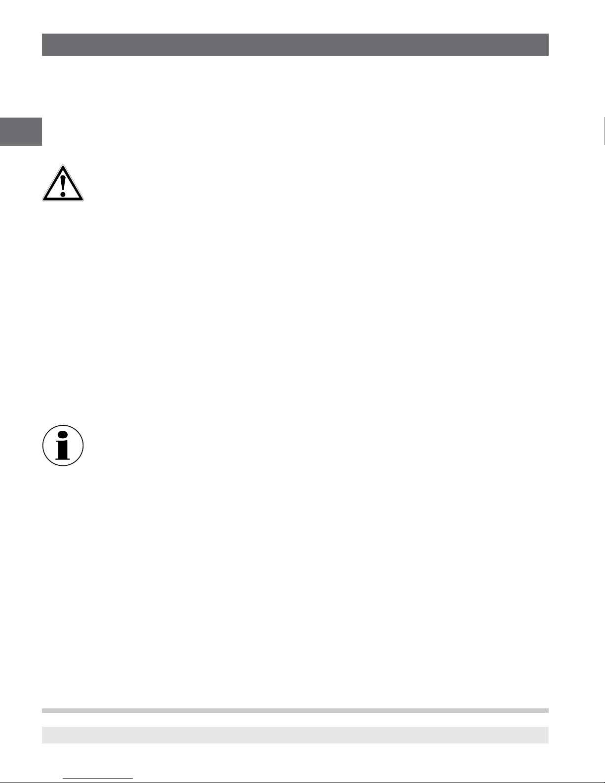
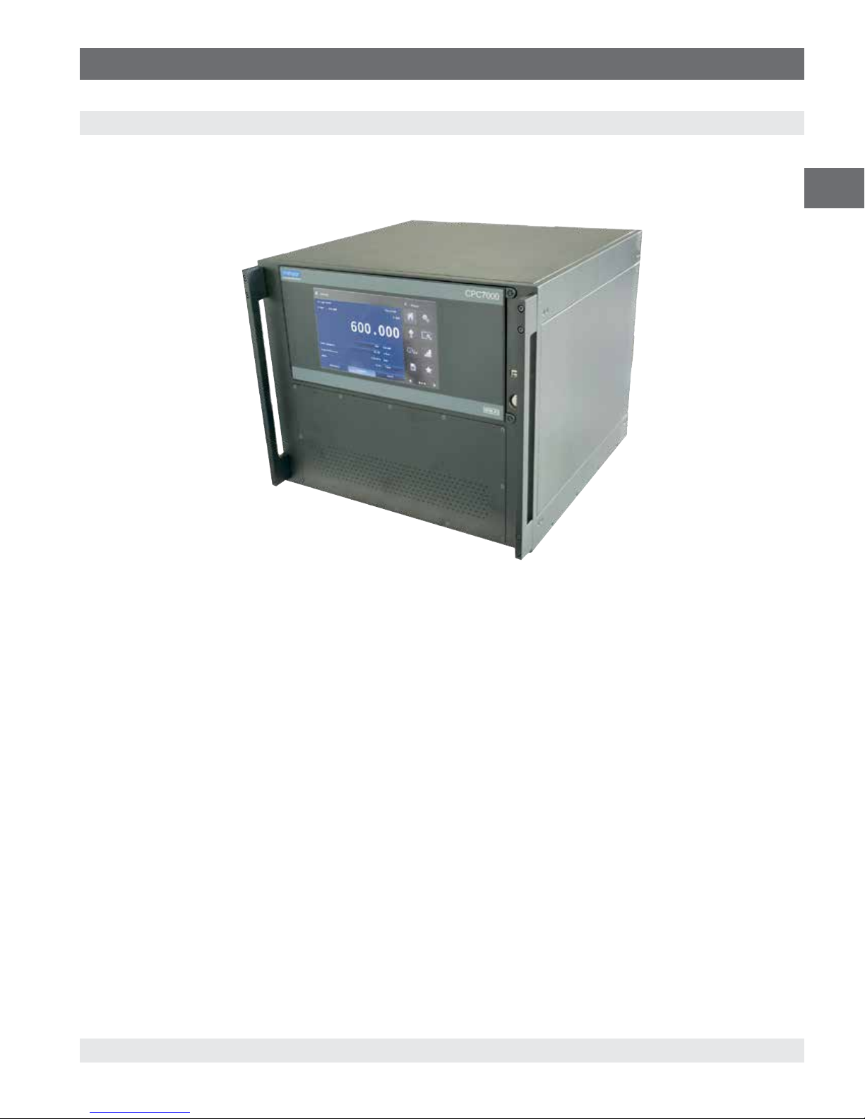
The CPC7000 pneumatic high pressure controller is a multi-range automatic pressure controller designed to test and calibrate a
variety of pressure devices such as pressure gauges, pressure switches, sensors, transducers and transmitters in either absolute
or gauge pressure modes. The CPC7000 can have up to three internal pressure reference transducers and an optional barometric
reference for gauge or absolute emulation. The CPC7000 is available as a desktop or a rack mountable instrument.
EN
Figure 2.1 Desktop version
2.1 Features
Here is a short list of significant features designed into the CPC7000:
■
Up to three removable / interchangeable, highly stable, temperature compensated, internal pressure transducers
■
Operating pressure range from 0… 700 bar (0 … 10,000 psi)
■
0.01% Intelliscale-50 accuracy
■
Easily removable transducers from the front of the CPC7000 This facilitates “out of instrument” recalibration of individual
transducers using the optional calibration sled
■
An optional removable / interchangeable internal high accuracy barometric reference transducer providing gauge pressure
emulation for absolute ranges and absolute pressure emulation for gauge ranges
■
8.9” color LCD display with touch screen
■
Multiple languages; change the language for on-screen text and number/date formats by simply touching one of the “national
flag” icons available in the setup screen.
■
Desk top or rack mount
■
Local operation, or command and read remotely
0019104001D 10/2018 EN
WIKA operating instructions pneumatic high pressure controller, model CPC7000
9
Page 10
2. Short overview
2.2 Turning On
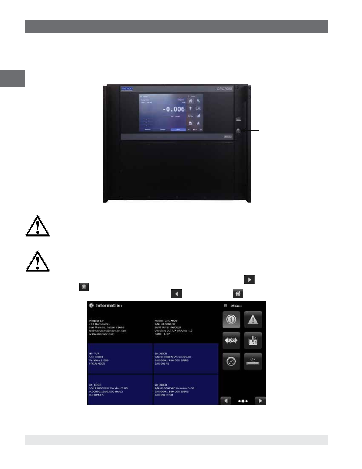
You can confirm that your CPC7000 is operational right now. Apply power to the power connector on the rear of the instrument
with the included power cord, remove any plastic plugs from the rear panel pressure ports, and press the power switch to ON. The
system will go through an initialization process, which takes about 30 seconds, and then a display will appear similar to the screen
shown below
EN
Power Switch ON/
OFF
Earth Ground! Any power adaptors or surge protection devices that negate the protective earth ground
should not be used. The power cord must be accessible and contain a protective earth ground. Do not
position the equipment so that it is difficult to remove the power cord.
Ventilation! Do not block airflow to ventilating fans located on rear of instrument.
To see information about the configuration of your new CPC7000, touch the Next Page Button [
Application (App) icon [
transducers that are installed. Press the Previous Page Button [
] on the menu and a window will appear listing the Mensor contact information, model number and the
] then the Home App [ ] to return to the main screen.
] then the Information
10
WIKA operating instructions pneumatic high pressure controller, model CPC7000
Figure 2.2 Information application
0019104001D 10/2018EN
Page 11
2. Short overview
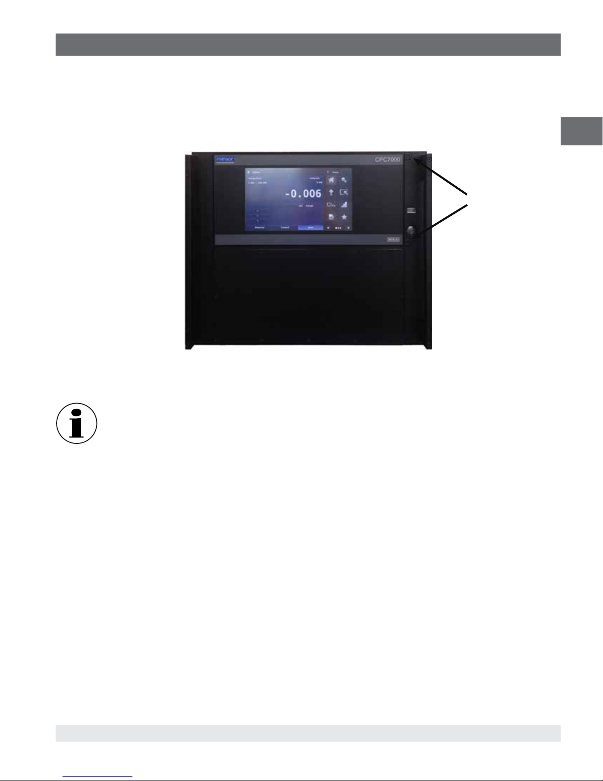
2.3 Front Panel
The CPC7000 front panel includes an 8.9” color LCD display with touch screen. Operator input is accomplished by pressing the
words or symbols and the App icons presented on the display. There is a single discrete on/off button and a USB on the right hand
side. The front panel is hinged for easy access to remove or replace the transducers inside. The instructions for accessing the
transducers are provided in Section 9.4 Transducer removale. The front panel also shows the model number designation and brand
logos
Screws to open
front panel
EN
2.3.1 Power Switch
The power switch is a two-state device with an action similar to that of a ball point pen. Push the button with enough force to latch it
in to turn the unit ON. Push it again to release it to turn the system OFF.
If power to the instrument is interrupted while ON it will shut down until the power is restored, then
immediately resume operation
2.3.2 USB Port
The front panel USB port is the Host USB and is intended for future expansion or software upgrades.
0019104001D 10/2018 EN
WIKA operating instructions pneumatic high pressure controller, model CPC7000
11
Page 12
2. Short overview
2.4 Display
The display is made up of two sections. In the main screen (“Home Application”), the left three fourths shows the operating screen
displaying the active pressure reading, units, mode (absolute or gauge), active range of the internal transducer, pressure control
setpoint, a bar graph (if enabled), an auto zero or tare button (if enabled) and any auxiliary displays that have been chosen. The
right one fourth of the screen has Application Icons (“Apps”) for setting general instrument settings, control settings, display
EN
settings, program settings, favorites plus a “Next Page” button [
for remote communication, troubleshooting, switch test, leak test, digital I/O and service applications.
Active transducer range
Optional Zero or Tare
Current Value
Units and Mode
Auxiliary Displays
] that, when pressed, shows a second and third page of icons
{
Operating Modes
Operating Screen Settings Apps
Buttons, Labels and Windows: The CPC7000 touch screen has many buttons with relevant graphic icons or text which, when
touched, will open a related window where changes can be made or information viewed. Some of these buttons will toggle from
one state to another, others present choices or display a numerical data entry screen. Text or icons that are displayed, but do not
respond to being touched, are called labels or windows. Operators will quickly become accustomed to the particular characteristics
of the frequently used buttons.
Main Screen: The main screen or “Home Application”, appears after power-up. This screen contains the operating screen and
Settings application screen. It will remain as configured after a power cycle.
Operating screen: The operating screen (left 3/4 of the main screen) contains information relevant
to the measurement. Up to three auxiliary displays can be shown simultaneously along with the current pressure value
2.5 Scope of Delivery
■
Pneumatic high pressure controller model CPC7000
■
Power cord with 1.5 m (5 ft) length
■
Operating instruction
■
Factory calibration certificate
Cross-check scope of delivery with delivery note.
12
WIKA operating instructions pneumatic high pressure controller, model CPC7000
0019104001D 10/2018EN
Page 13
3. Safety
3. Safety
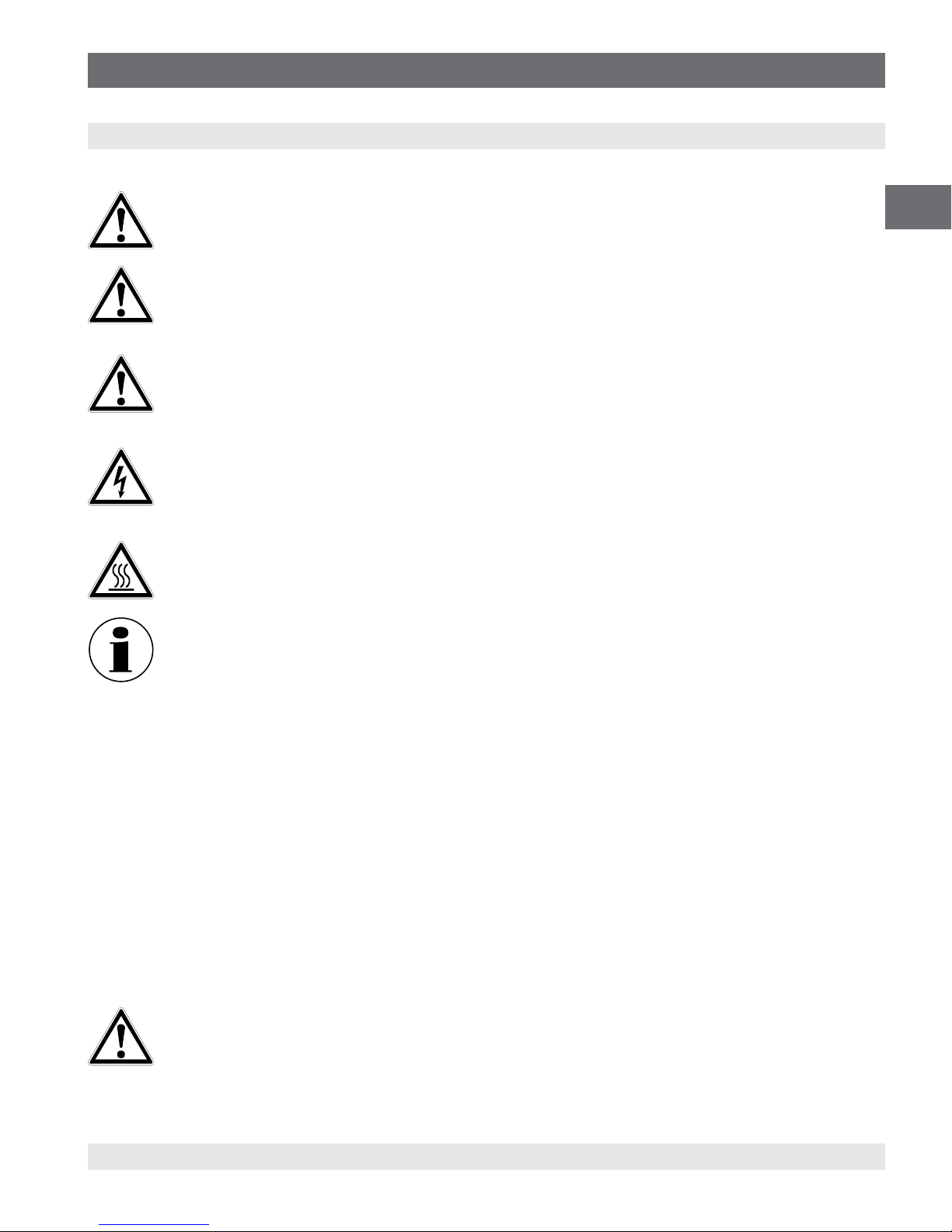
3.1 Explanation of Symbols
DANGER!
... indicates a directly dangerous situation resulting in serious injury or death, if not avoided.
WARNING!
... indicates a potentially dangerous situation that can result in serious injury or death, if not avoided.
CAUTION!
... indicates a potentially dangerous situation that can result in light injuries or damage to property or the environment,
if not avoided.
DANGER!
... identifies hazards caused by electrical power. Should the safety instructions not be observed, there is a risk of
serious or fatal injury.
WARNING!
... indicates a potentially dangerous situation that can result in burns, caused by hot surfaces or liquids, if not avoided.
Information
... points out useful tips, recommendations and information for efficient and trouble-free operation.
EN
3.2 Intended Use
The CPC7000 pneumatic high pressure controller is designed to automate the testing and calibration of pressure devices and
instruments for pressures up to 10,000 psi. Up to three removable / interchangeable pressure transducers are available in full
scale (FS) ranges from 1500 to 10,000 psi (100 to 700 bar) gauge or absolute. Each transducer module is configured with its own
calibration parameters on board and have 0.01% FS or optional 0.01% IS-50 uncertainty.
The three transducers, in combination with the special control valve regulator, provide a dynamic output. The operator can choose
to control pressure either using a single, selected transducer or auto-range control across all three transducers. The three ranges
can be chosen to optimize uncertainty levels across the full pressure span of the instrument.
In addition to the capacity for three active ranges, a fourth, barometric transducer is available as an option. With this option installed
a CPC7000, with absolute or gauge pressure transducers, can emulate pressure of the opposite type.
The operational safety on the instrument is achieved with relief valves and blow out disks to ensure overpressure protection along
with automatic venting of unused transducers.
CAUTION!
Instrument is intended to be used with pressure media Nitrogen (Class 2.8 or better) only.
0019104001D 10/2018 EN
WIKA operating instructions pneumatic high pressure controller, model CPC7000
13
Page 14
3. Safety
CAUTION!
Instrument is intended to be used up to a maximum altitude of 2,000 meters
EN
CAUTION!
Instrument is intended to be used just indoors and in a dry environment
WARNING!
The pressurized volume of the device under test including any tubing and manifold should not exceed 100 cc.
This instrument is not permitted to be used in hazardous areas!
The instrument has been designed and built solely for the intended use described here, and may only be used accordingly.
The technical specifications contained in these operating instructions must be observed. Improper handling or operation of the
instrument outside of its technical specifications requires the instrument to be taken out of service immediately and inspected by
an authorised WIKA service engineer.
Handle electronic precision measuring instruments with the required care (protect from humidity, impacts, strong magnetic fields,
static electricity and extreme temperatures, do not insert any objects into the instrument or its openings). Plugs and sockets must
be protected from contamination.
The manufacturer shall not be liable for claims of any type based on operation contrary to the intended use.
3.3 Improper Use
WARNING!
Injuries through improper use
Improper use of the instrument can lead to hazardous situations and injuries.
▶
Refrain from unauthorised modifications to the instrument.
▶
Do not use the instrument within hazardous areas.
▶
Do not use the instrument with abrasive or viscous media.
Any use beyond or different to the intended use is considered as improper use. Do not use this instrument in safety or emergency
stop devices.
3.4 Responsibility of the Operator
The instrument is used in the industrial sector. The operator is therefore responsible for legal obligations regarding safety at work.
The safety instructions within these operating instructions, as well as the safety, accident prevention and environmental protection
regulations for the application area must be maintained.
The operator is obliged to maintain the product label in a legible condition.
To ensure safe working on the instrument, the operating company must ensure
■
that the operating personnel are regularly instructed in all topics regarding work safety, first aid and environmental protection
and know the operating instructions and in particular, the safety instructions contained therein.
■
that the instrument is suitable for the particular application in accordance with its intended use.
■
that personal protective equipment is available.
14
WIKA operating instructions pneumatic high pressure controller, model CPC7000
0019104001D 10/2018EN
Page 15

3. Safety
3.5 Personnel Qualification
WARNING!
Risk of injury should qualification be insufficient
Improper handling can result in considerable injury and damage to equipment.
▶
The activities described in these operating instructions may only be carried out by skilled personnel who have the
qualifications described below.
Skilled personnel
Skilled personnel, authorised by the operator, are understood to be personnel who, based on their technical training, knowledge
of measurement and control technology and on their experience and knowledge of country-specific regulations, current standards
and directives, are capable of carrying out the work described and independently recognising potential hazards.
Operating personnel
The personnel trained by the operator are understood to be personnel who, based on their education, knowledge and experience,
are capable of carrying out the work described and independently recognising potential hazards.
Special knowledge for working with instruments for hazardous areas:
The skilled (electrical) personnel must have knowledge of ignition protection types, regulations and provisions for equipment in
hazardous areas.
EN
0019104001D 10/2018 EN
WIKA operating instructions pneumatic high pressure controller, model CPC7000
15
Page 16
3. Safety
3.6 Personal Protective Equipment
The personal protective equipment is designed to protect the skilled personnel from hazards that could impair their safety or health
during work. When carrying out the various tasks on and with the instrument, the skilled personnel must wear personal protective
equipment.
EN
Wear safety goggles!
Protect eyes from flying particles and liquid splashes.
Wear safety shoes!
Protect feet from falling objects or objects lying around, as well as against toxic or hazardous liquids and aggressive
media.
3.7 Labelling, Safety Marks
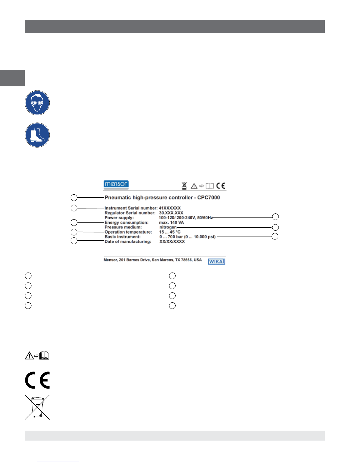
3.7.1 Product Label
1
2
4
6
8
1
Model
2
Serial number (Instrument and Regulator)
3
Power supply
4
Energy consumption
3.7.2 Symbols
Before mounting and commissioning the instrument, ensure you read the operating instructions!
CE, Communauté Européenne
Instruments bearing this mark comply with the relevant European directives.
5
Pressure medium
6
Operating temperature
7
Pressure rating
8
Date of manufacturing
3
5
7
This marking on the instruments indicates that they must not be disposed of in domestic waste. The disposal is
carried out by return to the manufacturer or by the corresponding municipal authorities (see EU directive 2012/19/
16
WIKA operating instructions pneumatic high pressure controller, model CPC7000
0019104001D 10/2018EN
Page 17
4. Transport, Packaging and Storage
EU).
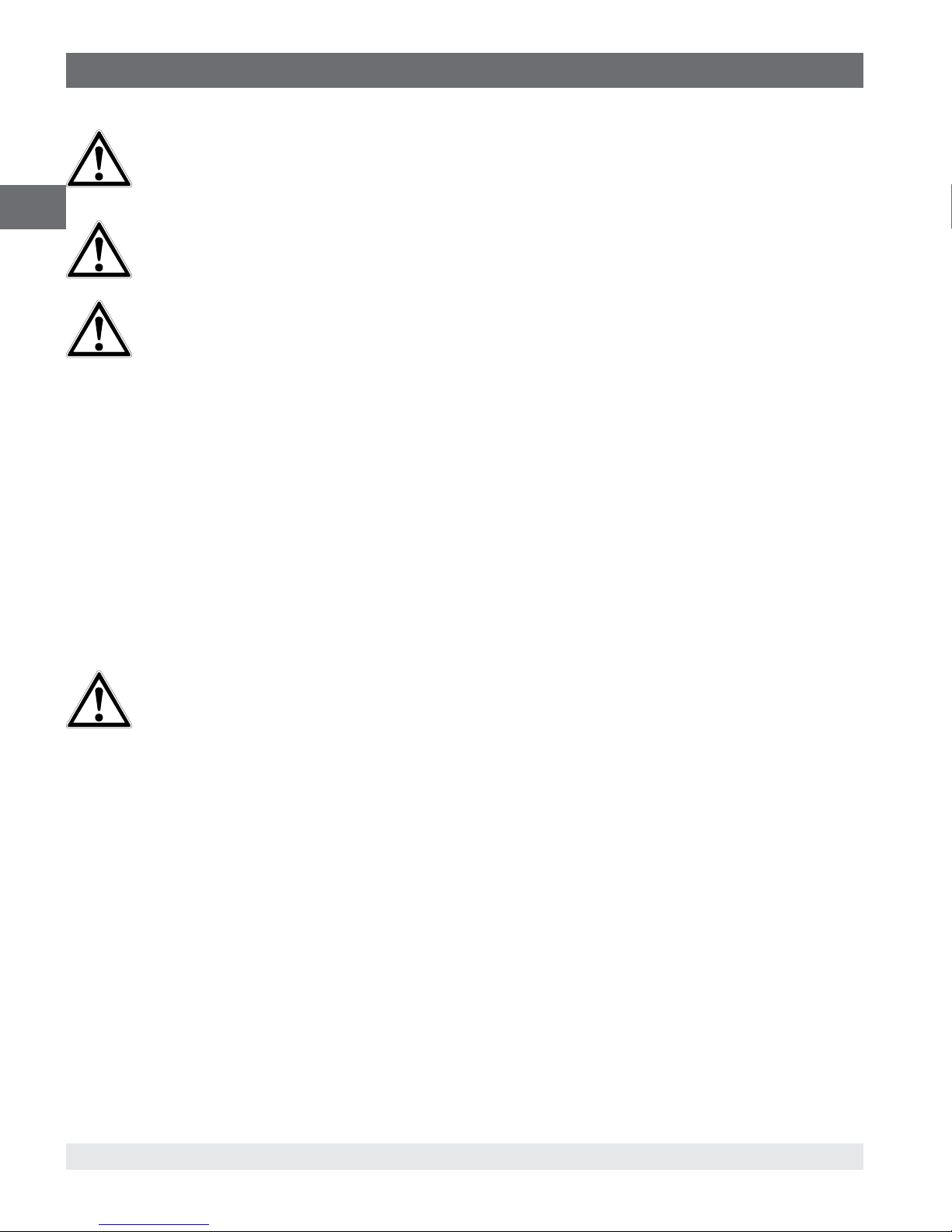
3.8 Warnings and Cautions
WARNING!
HIGH PRESSURE! High pressure gases are potentially hazardous. Energy stored in these gases and liquids can
be released suddenly and with extreme force. High pressure systems should be assembled and operated only by
personnel who have been trained in proper safety practices.
WARNING!
NOT EXPLOSION PROOF! Installation of this instrument in an area requiring devices rated as intrinsically safe is not
recommended.
WARNING!
POSSIBLE INJURY! The tubing, valves, and other apparatus attached to the gauge must be adequate for the
maximum pressure which will be applied, otherwise physical injury to the operator or bystanders is possible.
CAUTION
USE THE PROPER PRESSURE MEDIUM! Use only clean, dry, nitrogren of class 2.8 or better unless otherwise
specified by Mensor. This instrument is not designed for air use.
CAUTION
As with most sensitive electronic equipment, switch the power switch off before connecting or disconnecting to a
power source to prevent data loss. Do not position the equipment so that it is difficult to disconnect the AC power
cord.
EN
WARNING!
Detachable main power supply cord delivered with inadequate ratings should not be used, it is recommended to use
the power cord delivered with the instrument. See Section 11 Specifications for power ratings.
Additional Warning and Caution notices are found throughout this manual.
0019104001D 10/2018 EN
WIKA operating instructions pneumatic high pressure controller, model CPC7000
17
Page 18

4. Transport, Packaging and Storage
4.1 Transport
Check the pneumatic high pressure controller model CPC7000 for any damage that may have been caused by transport.
EN
Obvious damage must be reported immediately.
CAUTION!
Damage through improper transport
With improper transport, a high level of damage to property can occur.
▶
When unloading packed goods upon delivery as well as during internal transport, proceed carefully and observe
the symbols on the packaging.
▶
With internal transport, observe the instructions in chapter 5.2 “Packaging and storage”.
If the instrument is transported from a cold into a warm environment, the formation of condensation may result in instrument
malfunction. Before putting it back into operation, wait for the instrument temperature and the room temperature to equalise.
4.2 Packaging and storage
Do not remove packaging until just before mounting.
Keep the packaging as it will provide optimum protection during transport (e.g. change in installation site, sending for repair).
Permissible conditions at the place of storage:
■
Storage temperature: 0 ... 70 °C
■
Humidity: 35 ... 85 % relative humidity (no condensation)
Avoid exposure to the following factors:
■
Direct sunlight or proximity to hot objects
■
Mechanical vibration, mechanical shock (putting it down hard)
■
Soot, vapour, dust and corrosive gases
■
Hazardous environments, flammable atmospheres
Store the instrument in its original packaging in a location that fulfils the conditions listed above. If the original packaging is not
available, pack and store the instrument as described below:
1. Wrap the instrument in an antistatic plastic film.
2. Place the instrument along with shock-absorbent material in the packaging.
3. If stored for a prolonged period of time (more than 30 days), place a bag containing a desiccant inside the packaging.
0019104001D 10/2018EN
18
WIKA operating instructions pneumatic high pressure controller, model CPC7000
Page 19
5. Installation
5. Installation
Personnel: Skilled electrical personnel
WARNING!
READ THSE INSTRUCTIONS BEFORE INSTALLATION!
Only use original parts (see chapter 11 “Accessories”).
CAUTION
Damage to the instrument
When working on open electrical circuits (printed circuit boards) there is a risk of damaging sensitive electronic
components through electrostatic discharge.
▶
The correct use of grounded working surfaces and personal armbands is required.
5.1 Mounting
The instrument can be set up on a desk top or it can be rack-mounted. Rack mount hardware is optional on the CPC7000 (see
Section Specifications11 and Section 12 Options and Accessories).
The special transducers used in the CPC7000 are relatively insensitive to tilt and vibration. However to further assure stability and
accuracy, avoid mounting the instrument on surfaces subject to excessive motor or machinery vibration
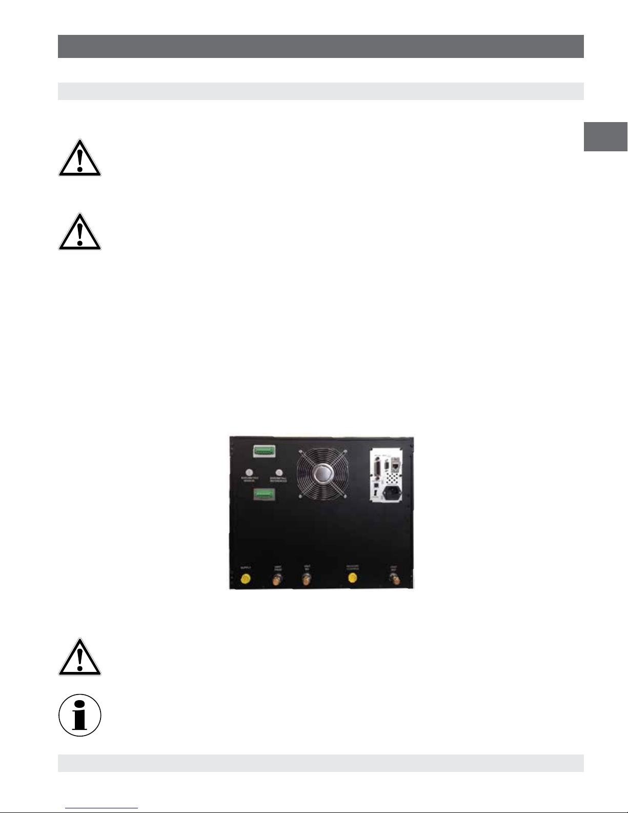
5.2 Rear Panel
Up to five pneumatic pressure ports are located across the bottom of the rear panel. The instrument with gauge transducers will
have a reference and a pressure port. The instrument with absolute transducers will use the pressure port. In the upper left corner
under the digital I/O connector is a M12 fitting , which is connected to the barometric reference sensor if installed. The connections
for digital I/O - 1 & 2 are located on the top on left side of the ventilation fan. Positioned on the right side is the RS-232, Ethernet,
IEEE- 488, USB device connections for communication, as well as a USB host connection and the 12 VDC power input.
EN
5.2.1 Rear Panel
WARNING!
The pressure connections must be installed according to the following instructions, observing the relevant
regulations. The installation is to be performed by trained, authorized personnel, knowledgeable in the safety
regulations for working on pneumatic/hydraulic systems
Up to 7 pressure connections are on the rear panel. Pressure connections that are not assigned are plugged.
0019104001D 10/2018 EN
WIKA operating instructions pneumatic high pressure controller, model CPC7000
Figure 5.2 Rear Panel
19
Page 20

5. Installation
5.2.2 Supply Port
The pressure supplied to the pressure connection labeled “Supply” should be approximately the greater of 30 ... 50 bar (435 ... 725
EN
psi) or 7-10% higher than the full scale of the highest pressure transducer installed in the controller.
5.2.3 VENT PROP Port
The pressure connection labeled “VENT PROP” is the port where the system pressure is vented to the atmosphere under certain
conditions. Leave this port as is.
5.2.4 VENT NO Port
The pressure connection labeled “Vent NO” is the port where the system pressure is vented to the atmosphere under emergent
conditions. Leave this port as is.
5.2.5 Measure / Control Port
The Measure / Control port (when in the Control mode) supplies pressure that is precisely controlled by the controller. In the
Measure mode, a pressure applied to the Measure / Control port is measured by the internal transducers.
5.2.6 Vent Ref Port
The pressure connection labeled “Vent Ref” is the port where the not in use reference transducer pressure is vented to the
atmosphere under certain conditions. Leave this port as is.
5.2.7 Barometric Reference Port
The barometric references port is available on gauge units that have transducers that are not sealed gauge units. For these units
this port is available to connect to the reference side of the transducer. This port is normally left open to atmosphere but may be
connected to a stable reference pressure. In an absolute pressure transducer this port is not used
5.2.8 Optional: Barometric Sensor Port
The Barometric Sensor port is connected to the optional internal barometer and should be left open to atmospheric pressure.
5.2.9 Remote Communication Connections
See Section 8, Remote Operation for connections and commands for operation over IEEE-488, Ethernet, USB or RS-232 ports.
5.2.10 Power Up
Apply power to the power connector on the rear of the instrument using the power adaptor included, and switch the power switch
on the front of the unit ON. The instrument will go through an initialization process and system check. As soon as the system check
is completed the system will default to a screen similar to the one shown in Section 6.1.2, Display Screen Features. The main
measurement screen may be configured in many different ways but initially it will be in a default configuration. Subsequently, the
unit will power up in the configuration that it was in when last powered off. Allow at least 15 minutes of warm up before performing
critical pressure measurements.
Do not position the equipment so that it is difficult to remove the power cord. The instrument is not intended for
connection of long-distance lines, i.e. lines within a building that are longer than 30 m, or that leave the building
(including lines of outdoor installations).
20
WIKA operating instructions pneumatic high pressure controller, model CPC7000
0019104001D 10/2018EN
Page 21
6. Operation
6. Operation
6.1 General Operation
This section describes the procedures for operating the CPC7000 from the front panel. Instructions for operating the device
remotely from an external computer are covered in Section 8, Remote Operation. By following the procedures provided in these
two sections and Section 9.2, Recalibration, you can expect your CPC7000 to deliver maximum accuracy and dependability for
many years of useful service.
6.1.1 Setup Applications
Configuration of the CPC7000 is achieved by changing settings accessed through the Application (“App”) buttons. Local operation
is accomplished by observing the data presented in the display. The appearance and functionality of the display can be changed
by pressing the App button for the related function. After an app has been chosen, a set of related parameters will appear on the
left. After choosing one of these parameters, a set of selections related to that parameter will appear on the right or a data entry
keypad. The desired selection or data can be entered here.
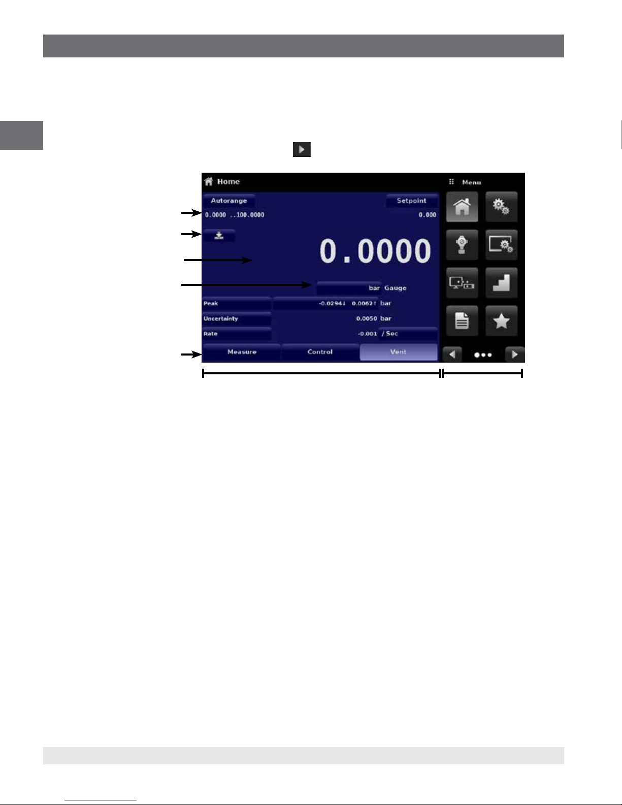
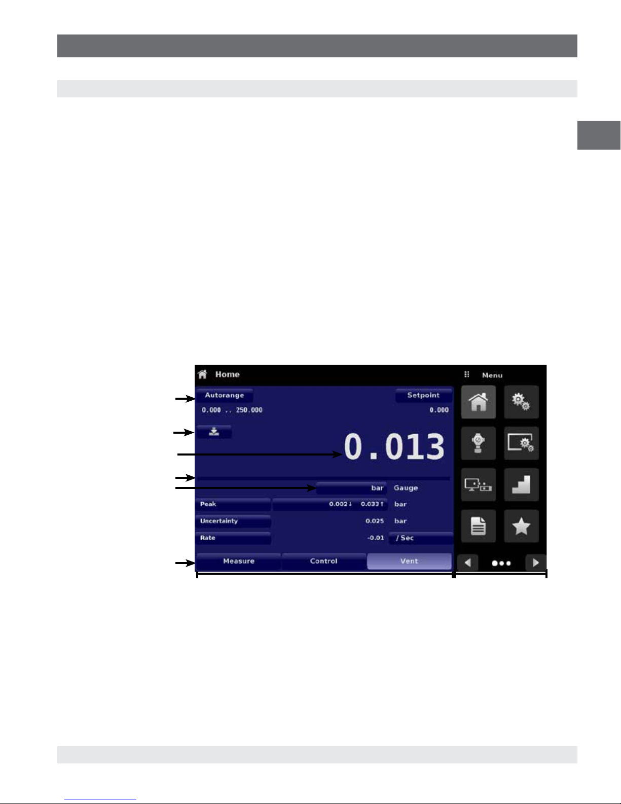
6.1.2 Display Screen Features
The screen shown below provides an overview of the features that may appear on the display after initialization. The left three
fourths of the display contains the area where information is displayed (in this case the Home Application) and the right one fourth
contains the selection icons for each application. A zero or tare button, bar graph and none or 3 of the 7 available auxiliary displays
(Peak, Rate, Rate Setpoint,Uncertainty, Units, Digital I/O and Source Pressure) will appear in the Home App if activated. All of the
CPC7000 screen features are described in more detail throughout this manual. The active App is represented with a light gray
background color compared to the other Apps.
EN
Active transducer
range
Optional Zero or Tare
Current Value
Optional Bar graph
Units / Pressure Type
Auxiliary Displays
Operating Modes
{
Operating Screen
Figure 6.1.2 Display Screen Features
Settings Apps
0019104001D 10/2018 EN
WIKA operating instructions pneumatic high pressure controller, model CPC7000
21
Page 22
6. Operation
6.2 Initial Setup
Section 6.2.1 and 6.2.2 are provided first so that the operator can initially check the information screen to verify the installed
components and to change the language if needed.
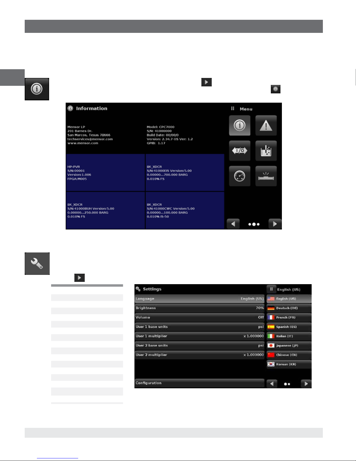
6.2.1 Contact and Version Information Application
EN
Navigate to additional Apps by pressing the Next Page button [ ] at the right bottom of the App buttons. This
gives access to the second page of the App selection area. Press the Information App button [
Mensor contact, installed transducers, installed regulator along with instrument and software version information
] to display
6.2.2 Language Selection
Pressing the settings application button will open a screen where the language, display brightness, volume, user
base units/multiplier and configuration loading/saving, can be changed. The current language selections available
are shown in the table below. Additional language choices will appear on the screen after pushing the Next Page
button [
Language Country
English USA
German Germany
French France
Spanish Spain
Italian Italy
Japanese Japan
Chinese China
Korean Korea
English Great Britain
English Canada
French Canada
Spanish Latin America
Polish Poland
Portuguese Portugal
Portuguese Brasil
Russian Russia
]:
Figure 6.2.1 Information
22
WIKA operating instructions pneumatic high pressure controller, model CPC7000
0019104001D 10/2018EN
Page 23
6. Operation
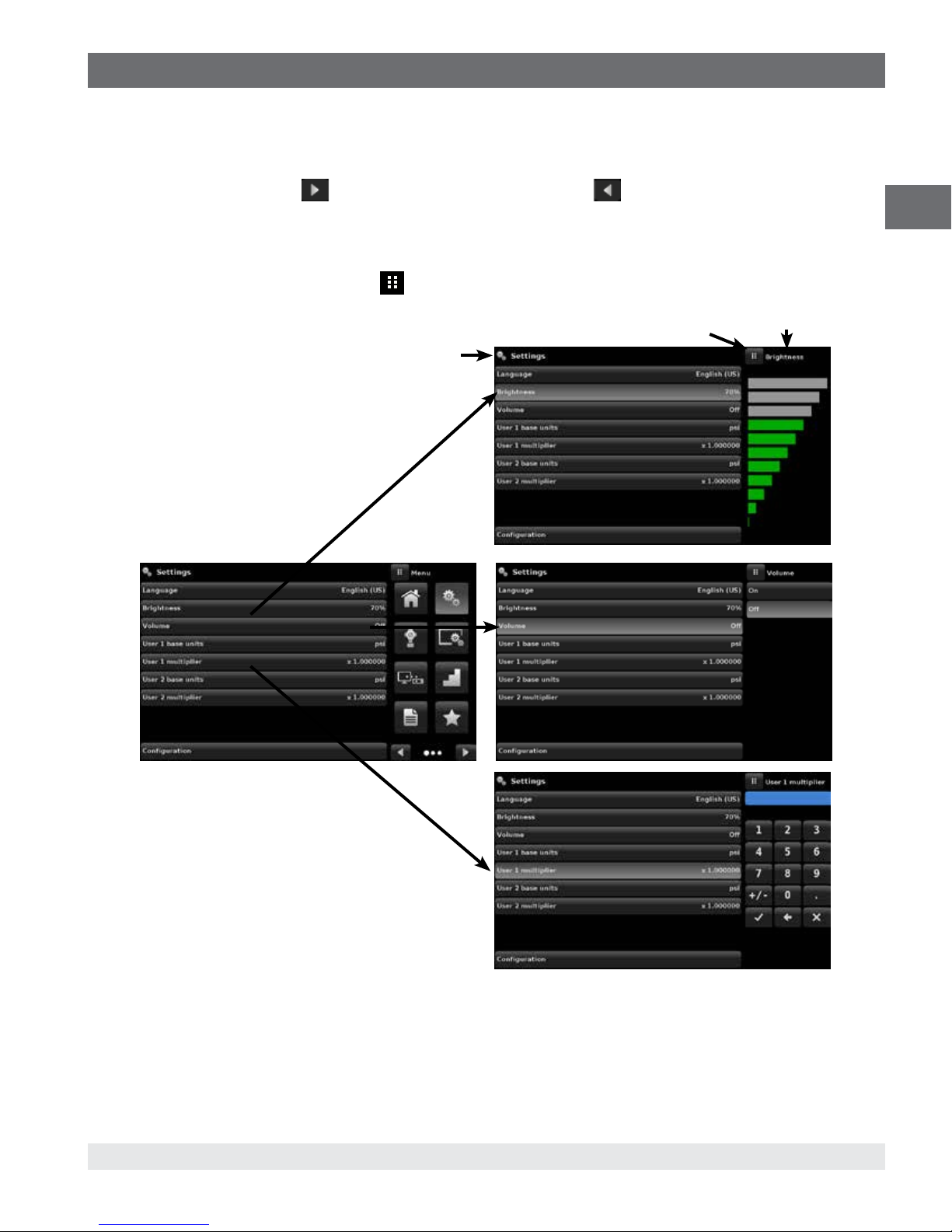
6.3 Application Selection and Parameter Inputs
The application selection area on the right one fourth of the screen (see Figure 6.1 Display Screen Features) is the area where
setup, information, calibration, service and other Apps can be chosen. Multiple pages of application selections can be accessed
by pressing the Next Page button [
on the bottom right indicate the active page by a larger circle. As each App is chosen, related application parameters will appear
on the left three fourth of the screen along with the name of the application, and a reduced size icon in the top title section. When
a parameter is chosen, related selections, sliding scales or a data entry key pad will appear in the input area on the right where
the application selection buttons were previously displayed. An example of each type of input is shown below. To return to the App
selection menu, simply press the Menu button [
intuitively apparent and will become second nature with minimal exposure to the menu structure.
] or by pressing the Previous Page button [ ] A series of horizontally placed circles
] above the input area. The purpose and use of each selection and menu is
Menu Button
Input Title
App Title
EN
0019104001D 10/2018 EN
WIKA operating instructions pneumatic high pressure controller, model CPC7000
23
Page 24
6. Operation
6.4 Applications
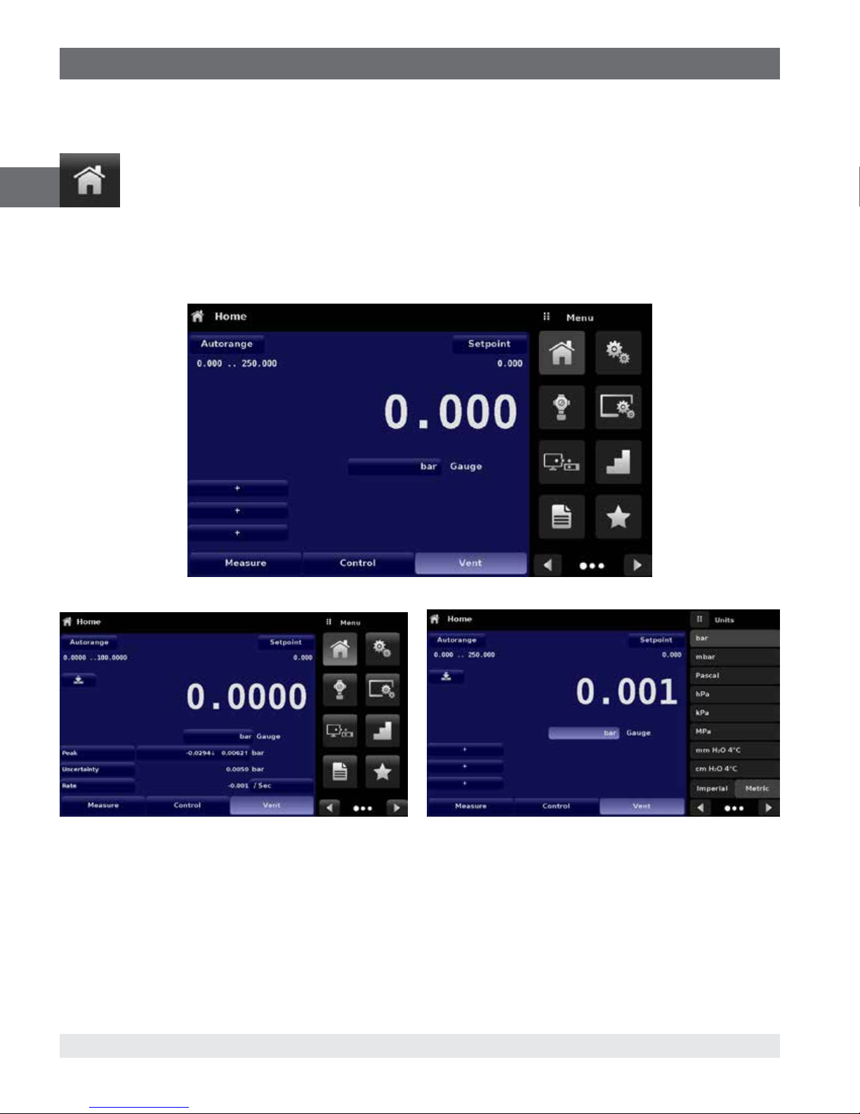
6.4.1 Home Applications
The Home App is the normal operation screen. This application is different from the others in that it is not used to
EN
The screen in Figure 6.4.1-A shows the basic Home App in an instrument. The user can change the display to show multiple
auxiliary displays by pressing the auxiliary button on the left corner of the screen (Figure 6.4.1-B Home App With Auxilliary). The
Units button is always displayed. When the Units button is pressed a selection of imperial and metric units will be displayed on the
right (Figure 6.4.1-C Pressure Units); notice that the Units button has a lighter background when the selection menu is active. If a
barometric reference is installed, the Mode button, described below, will toggle from Gauge to Absolute mode when pressed.
setup the configuration but is used to monitor the pressure applied to the installed transducers
Figure 6.4.1-A Basic Home App
Figure 6.4.1-B Home App with Auxiliary Display Figure 6.4.1-C Pressure Units
24
WIKA operating instructions pneumatic high pressure controller, model CPC7000
0019104001D 10/2018EN
Page 25
6. Operation
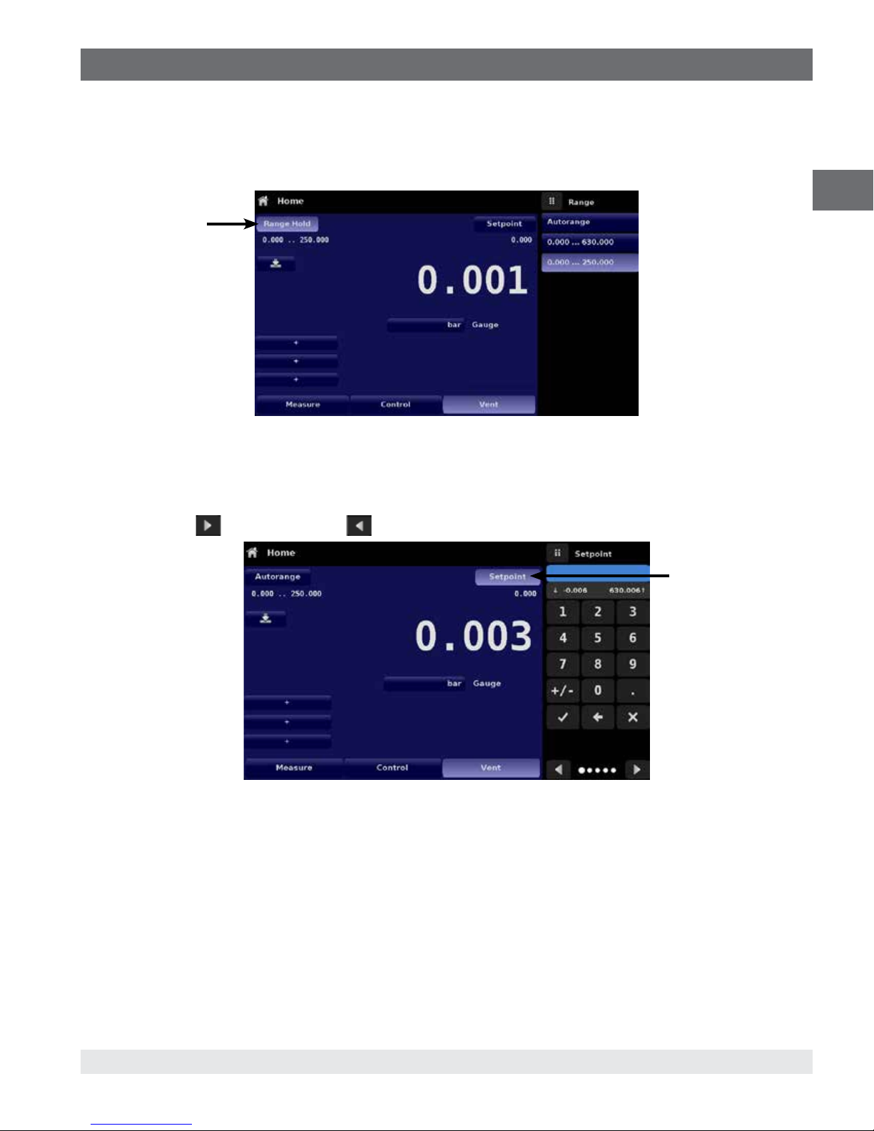
6.4.1.1 Range Hold/ Autorange
The Range Hold / Autorange button allows the user to select the active range of the transducers. By clicking the Range Hold
button, the user can select the active transducer from the primary, secondary and tertiary transducers or utilize the “Autorange”
feature to let the instrument automatically select the active range based on the current pressure value.
Range Hold button
Figure 6.4.1.1 Range Hold Button
6.4.1.2 Control Setpoint
The Setpoint button allows the user to enter the desired pressure value to be controlled by the instrument. There are multiple ways
of entering the control setpoint: numeric keypad, step increments, percentage entry, digital step or a program data entry. These
methods can be accessed by the user by pressing the “Setpoint” button and the various setpoint entry methods can be navigated
with the Next Page [
] and Previous Page [ ] buttons.
EN
Figure 6.4.1.2 Setpoint Button
Setpoint button
0019104001D 10/2018 EN
WIKA operating instructions pneumatic high pressure controller, model CPC7000
25
Page 26
6. Operation
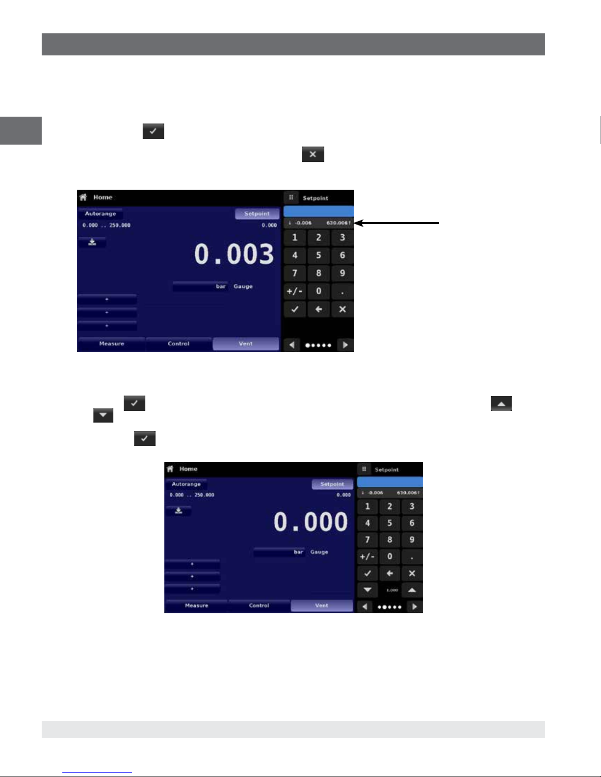
6.4.1.2.1 Numeric Keypad
The first entry method provides 10 digits for numeric entry, plus the decimal point and a sign key (Figure 6.4.1.2.1 Numeric Keypad
Setpoint Entry). The sign key [+/-] will toggle between positive and negative values. Each stroke on the key pad will echo in the
blue input value window above the pad. A change between plus and minus values [+/-] can be entered at any time during the string
entry. Pressing the Enter [
EN
value when the Enter button is pressed the system will respond with an error tone and the entry will turn red. When that happens
determine the cause of rejection, delete the entry using the Delete [
can only be entered within the minimum and maximum control range set in the Control Settings App (6.4.3 Control Settings
Application). These limits are shown above the numeric entry keypad.
] button will accept the value and it will become the setpoint. If the input window holds an illegal
] button and then enter a valid number. The setpoint
Min & Max
setpoint values
Figure 6.4.1.2.1 Numeric Keypad Setpoint Entry
6.4.1.2.2 Step Increments
The second entry method allows the user to enter the setpoint in the same way as the Numeric Keypad by keying in the value and
then pressing Enter [
Step Down [
setpoint value. Subsequent touches of the Step Up or Step Down button will continue to increase or decrease the setpoint by the
step value. If the Enter [
rather than a step value.
] button, without pressing the Enter button. This number will then be used to decrease or increase the existing
] button. The user can then enter the desired value of step increment and press Step Up [ ] or
] button is pressed the newly entered value will register as a new setpoint value on the Home Screen
Figure 6.4.1.2.2 Numeric Keypad with Step Increments
26
WIKA operating instructions pneumatic high pressure controller, model CPC7000
0019104001D 10/2018EN
Page 27
6. Operation
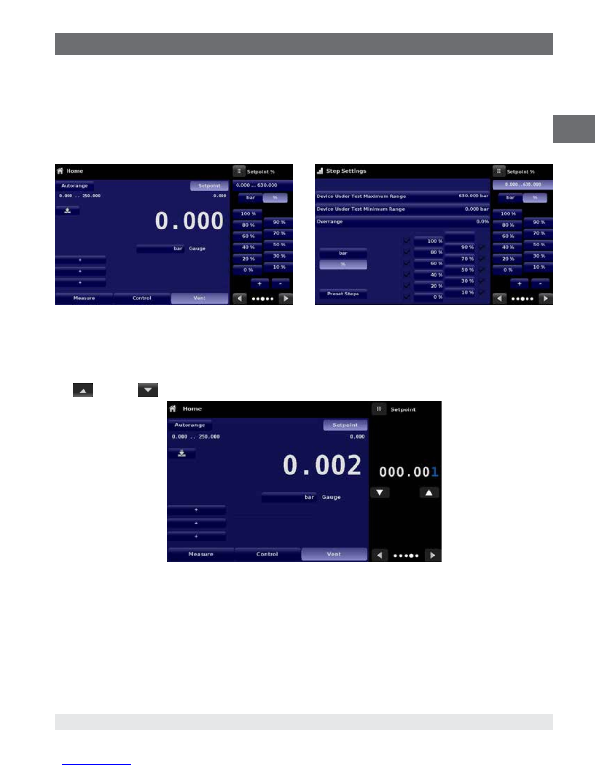
6.4.1.2.3 Percentage Entry
The third entry method is the Percentage Entry method (Figure 6.4.1.2.3-A Percentage Entry) which allows the user to select
a setpoint value as a percentage of the pressure range of device under test (DUT). The user can choose between various
percentage values by clicking on the desired button. The setpoint will instantly change to the selected percentage value of the DUT.
The user can also configure the minimum and maximum pressure values of the DUT by clicking the button displaying pressure
range. This would take the user to the Step Settings App (Figure 6.4.1.2.3-B Step Settings App) which is explained in Section 6.4.6
Step Settings Application.
Figure 6.4.1.2.3-A Percentage Entry Figure 6.4.1.2.3-B Step Percentage
EN
6.4.1.2.4 Digital Step Entry
The fourth entry method is the Digital Step data entry method. This method allows the user to increase or decrease the setpoint
value by one digit at a time. The digit to be changed can be selected from a string of five zeroes (0) and one blue numeral one (1)
by sliding a finger across the zeroes and converting the desired digit to a blue 1. The right most digit in the Digital Step corresponds
to the lease significant digit of the setpoint. Each digit of the setpoint can then be increased or decreased by pressing the
Up [
] or Down [ ] button.
Figure 6.4.1.2.4 Digital Step Entry
0019104001D 10/2018 EN
WIKA operating instructions pneumatic high pressure controller, model CPC7000
27
Page 28
6. Operation
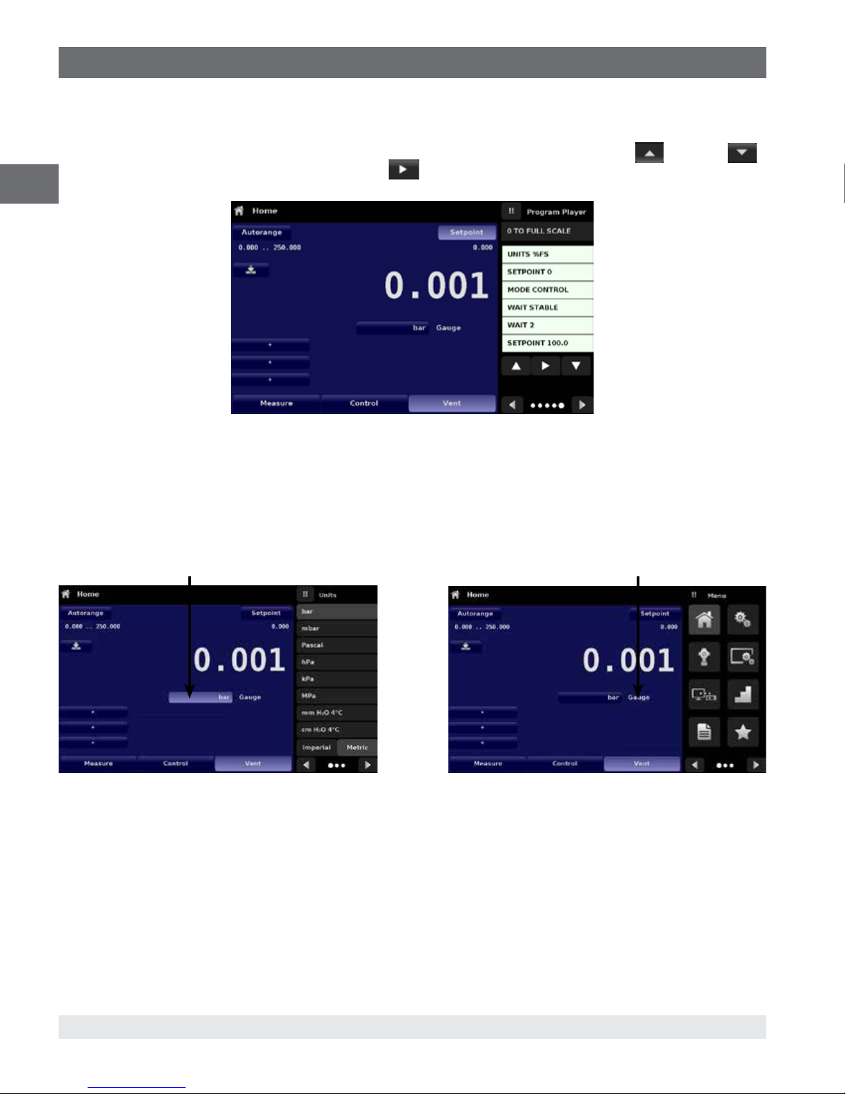
6.4.1.2.5 Program Data Entry
The fifth entry method is through the automated Programs stored in the CPC7000 memory. The Program Player allows the user to
select one of the stored Programs and use it for setpoint entry. A Program can be chosen by using the Up [
buttons. After selecting the desired program, press the Play [
Player and how to create/ edit programs is available in Section 6.4.7, Programs Application.
EN
Figure 6.4.1.2.5 Program Data Entry
6.4.1.3 Units and Pressure Type
The Units button is always displayed. When the units button is pressed a selection of imperial and metric units will be displayed
on the right (Figure 6.4.1.3-A).The Pressure Type button is only active if there is an optional Barometer installed. Otherwise, the
Pressure Type button becomes a label (Figure 6.4.1.3-B) indicating the native mode of the instrument (absolute or gauge). When
an optional barometer is installed, a native gauge transducer can emulate absolute pressure using the barometric reference.
Alternatively, a native absolute transducer can emulate gauge pressure. Emulation can be activated simply by pressing the
Pressure Type button
Pressure Units button
] button to start the program. More information on the Program
Pressure Type button
] or Down [ ]
Figure 6.4.1.3-A Pressure units Figure 6.4.1.3-B Pressure type
6.4.1.4 Bar Graph
An optional bar graph can be displayed below the current pressure value. The bar graph indicates the relative position of the
current value within the maximum range of the primary transducer. This bar graph will appear in the Home App when selected from
the Display Settings App (Section 6.4.4).
28
WIKA operating instructions pneumatic high pressure controller, model CPC7000
0019104001D 10/2018EN
Page 29

6. Operation
6.4.1.5 Auxiliary Displays
The screen in Figure 6.4.1.5-A shows all of the possible auxiliary display items that can be included in the Home App. The
instrument can have up to three auxiliary displays which can be chosen by clicking on each button and then selecting the display
item from the menu on the right side of the screen (Figure 6.4.1.5-B)
Figure 6.4.1.5-A Home App with Auxiliary Displays Figure 6.4.1.5-B Auxiliary Display Selection
Some of the auxiliary display can be modified by pressing the displayed button. Others simply display auxiliary information.
■
Peak: Pressing the Peak button will reset the upper and lower peak value to the current reading, subsequent negative or
positive divergence from that reading will be recorded in the button.
■
Rate: Pressing the Rate button will display a choice of time rate units for the rate denominator.
■
Rate Setpoint: Pressing the Rate Setpoint button will let the user enter the new Rate Setpoint via the numeric Keypad
(“Variable”) or select “Slow” (.1% of the span of the primary transducer), Medium (1% of the span of the primary transducer), or
“Fast” (10% of the span of the primary transducer).
■
Uncertainty: Displays the accuracy at the pressure being displayed.
■
Units: Pressing the Auxiliary Units button will display the same set of units available for the primary units. Pressing any of these
units will change the auxiliary units to that chosen unit.
■
Digital I/O: Displays the current state of digital inputs and outputs as “1” for high and “0” for low.
■
Source Pressure: Displays the current source pressure at the supply port.
EN
6.4.1.6 Zero Button
If the Zero Calibration function has been chosen in the Display Settings App (Section 6.4.4), then the Zero Cal Button [ ]
will appear in the Home App. If the instrument is measuring absolute pressure, and the Zero Cal Button is pressed, a keyboard will
appear to allow a single point calibration. If the instrument is measuring gauge pressure, pressing the button will set the current
reading to zero. If the instrument is in emulation mode (absolute or gauge) then the value will not be saved to the transducer but
only as a temporary adjustment while in emulation mode. After exiting the emulation mode or after a power cycle, the temporary
adjustment will be cleared. The zero adjustment for an instrument not in emulation mode will be saved to the transducer as if single
point calibration had been performed.
Figure 6.4.1.6 shows the zero cal function been enabled for instrument. The background color of the zero button will momentarily
change to a lighter color as the zero calibration is performed then will revert back to a darker color when complete. The screen on
the right shows this.
0019104001D 10/2018 EN
WIKA operating instructions pneumatic high pressure controller, model CPC7000
29
Page 30

6. Operation
EN
Figure 6.4.1.6 Zero Button
6.4.1.7 Tare Button
If the Tare calibration function has been chosen in the Display Settings App (Section 6.4.4), then the Tare
Button [
in yellow when active. The Tare button and the Zero Button cannot appear on the screen at the same
time. When the Tare button is pressed, the instrument will subtract the current pressure reading (the tare
pressure) so that the indicator will display zero. Subsequent deviations in pressure will be relative to the
tare pressure.
] will appear in the Home screen. For safety reasons, the tare button will be highlighted
Tare button
Figure 6.4.1.7 Tare Button
Pressing the tare button again will deactivate the tare and change the pressure indication back to the reading corresponding to the
calibrated output of the transducer. An active tare will revert to a deactivated state after a power cycle.
30
WIKA operating instructions pneumatic high pressure controller, model CPC7000
0019104001D 10/2018EN
Page 31

6. Operation
6.4.1.8 Operating Mode Selection
The operating modes are permanently displayed on bottom of the Home App. The CPC7000 has three operating modes: Measure,
Control and Vent. After the system has switched on, the instrument will automatically be placed in Vent mode. The user can switch
from one mode to the other by using the mode selection keys.
When switching from Control mode to Measure mode, the system will not be vented and the last applied pressure
will be locked in the system by means of a solenoid valve
■
Measure Mode: In Measure mode the CPC7000 acts like a precision pressure measuring instrument and measures the
pressure applied at the Measure/Control port. If the Control mode was the last used mode before switching into Measure mode,
the last controlled pressure is held in the test assembly.
■
Control Mode: In Control mode the CPC7000 provides a controlled pressure at the Measure/Control port equal to the setpoint
value. It is activated by pressing the Control button. In order to ensure smooth operation in the control mode, following measures
must be taken and respective parameters must be set.
The control stability and the control rate can be set in the Control Settings App [
Control limits can be set in the Control Settings App [
■
Vent Mode: The Vent function will vent the system to the atmosphere, including the test assembly connected to the Measure/
Control port. The Vent mode can be activated from the Measure or Control mode by pressing the Vent button. The rate at which
the pressure is released in vent mode is set in the Control Settings App [
WARNING!
Venting will cause a loss of pressure at the vent rate in the system and the plumbing connected to the Measure/
Control port. Care must be taken that the device under test is not damaged during venting.
]
]
]
EN
6.4.2 Settings Application
The Settings App is used to set up general settings for the display. Settings parameters include Language,
Brightness, Volume, User 1 base units, User 1 multiplier, User 2 base units, User 2 multiplier, Barometer units, and
Configuration. Figure 6.4.2 Settings application shows these parameters as indicated when the Settings App has
been chosen. As each parameter is pressed, an input screen will appear on the right where selections can be made.
The Settings App provides a place to change the language, display brightness, volume, user units, and barometer units.
Configuration settings of the unit can also be saved within this application plus the default configuration can be activated.
Figure 6.4.2 Settings App
0019104001D 10/2018 EN
WIKA operating instructions pneumatic high pressure controller, model CPC7000
31
Page 32

6. Operation
6.4.2.1 Languages
The Language parameter provides a selection of different languages. Once a language is chosen all words within all menus will
appear in the chosen language and the radix character (decimal mark) will change from a dot (.) to a comma (,) depending on the
language chosen. More languages can be accessed by navigating to the next page of the language selection menu on the right
side of the screen.
EN
Figure 6.4.2.1 Languages
6.4.2.2 Brightness
The Brightness setting provides a sliding scale to increment the screen brightness in all screens. Sliding your finger along the bar
graph or touching anywhere in the bar graph will change the brightness of the screen. After the setting is made and your finger is
removed from the screen the menu will show the brightness percent selected and revert back to the main settings menu.
Figure 6.4.2.2 Brightness
32
WIKA operating instructions pneumatic high pressure controller, model CPC7000
0019104001D 10/2018EN
Page 33

6. Operation
6.4.2.3 Volume
The Volume setting provides a way to turn on or off the touch screen audio feedback.
Figure 6.4.2.3 Volume
EN
6.4.2.4 User Base Units/ Base Units Multiplier
When choosing a unit of measure from the Home Application (main screen), standard units can be chosen in addition to two user
defined units. User units 1 and 2 are defined in the Settings App using “User 1 base units”, “User 1 multiplier” and / or “User 2 base
units”, “User 2 multiplier”. If the display of a special unit is needed, then a base unit should be chosen (psi, bar or Pascal) as the
“User base unit” and the “User multiplier” can be entered to derive the special unit using the formula: Special unit = Base Unit x
Unit multiplier. When set this way, and the user unit has been chosen from the main screen, then the user unit will now display the
Special unit as derived.
0019104001D 10/2018 EN
WIKA operating instructions pneumatic high pressure controller, model CPC7000
Figure 6.4.2.4 User base units/ Base units multiplier
33
Page 34

6. Operation
6.4.2.5 Barometer Units
When the Barometer Units button has been chosen, a list of Imperial or Metric units is presented on the
right side of the screen. Any of these units can be chosen from this list for the barometric readout. The
barometric pressure readout can be seen on the bottom right of the Home App.
EN
Figure 6.4.2.5 Barometer units
6.4.2.6 Configuration
Configuration is the last parameter in the Settings App. It allows the operator to save instrument settings and load them as a
group, as needed, in the future. Configuration variables that are currently set in all Apps can be saved using the Configuration
“Save” button and recalled using the Configuration “Load” button. Simply set all desired variables in each app, then go to
Settings-Configuration, press one of the numbered Configuration buttons then press the “Save” button. This will save the current
configuration in that button. To reload a saved configuration at a later time, go to Settings-Configuration and press the numbered
configuration button corresponding to the saved configuration and then press the “Load” button.
The instrument default conguration can be activated simply by pressing the “Default” Button.
34
WIKA operating instructions pneumatic high pressure controller, model CPC7000
Figure 6.4.2.6 Configuration
0019104001D 10/2018EN
Page 35

6. Operation
6.4.3 Control Settings Application
The Control Settings App allows the user to select and configure the control parameters for the instruments pressure
regulating module (PVR module). Figure 6.4.3 shows the Control Settings Application screen.
Figure 6.4.3 Control Settings App
EN
6.4.3.1 Control Limits
The Maximum and Minimum Limit buttons in the Control Settings App provide a place to limit the set point value that can be
chosen in the Home App. These limits can only be set within the range of the active transducer. When the instrument is in
Autorange the limits can only be set within the range of the primary transducer which, by convention, will have the widest range.
The minimum limit must be lower than the maximum limit. The user cannot enter set points and thereby not control to pressures
outside of these limits. Figure 6.4.3.1 shows the data entry keyboard to enter the limits. Note that the keyboard displays the
maximum value that can be entered.
Figure 6.4.3.1Control limit setting
0019104001D 10/2018 EN
WIKA operating instructions pneumatic high pressure controller, model CPC7000
35
Page 36

6. Operation
6.4.3.2 Stability Parameters
Stability parameters for the controlled pressure can be configured using the Stable Window and Stable Delay buttons. When the
controller enters a stable condition the pressure indication color on the Home App will change from white to green. The Stable
Window button allows the user to enter a value as a percentage of the highest range transducer. This value represents the
pressure window within which any setpoint value would be considered stable by the user. The Stable Delay button lets the user
EN
add a desired delay until the pressure value is considered stable while being in the stable window.
Stability
Parameters
Figure 6.4.3.2 Stability Parameters
6.4.3.3 Rate Setpoint
The Rate Setpoint button allows the user to set the rate of pressure change when the CPC7000 is controlling up or down to a
setpoint (Figure 6.4.3.3). The rate is limited from 1 bar/second to 10% of span of active range of the transducer / second upto a
maximum of 10 bar/second.
Figure 6.4.3.3 Rate Setpoint
36
WIKA operating instructions pneumatic high pressure controller, model CPC7000
0019104001D 10/2018EN
Page 37

6. Operation
6.4.3.4 Rate Stability Parameters
Rate parameters for the control rate can be found in the Control Settings App and can be configured using the Rate Stable Window
and Rate Stable Delay buttons. The Rate Stable Window button allows the user to enter a value as a percentage of the active
range of transducer. This value represents the pressure window within which the control rate value would be considered stable by
the user. The Rate Stable Delay button lets the user add a desired delay until the control rate is considered stable while being in
the rate stable window.
Rate Stability
Parameters
EN
Figure 6.4.3.4 Rate Stability Parameters
6.4.3.5 Vent Rate
The Vent Rate button in the Control Settings App lets the user to determine the rate at which pressure will vent in vent mode. By
default the rate of the vent is set similar to the control rate. Figure 6.4.3.5 displays the vent rate setting. The maximum allowable
rate of vent is 60 bar/second and the minimum vent rate is limited to 1 bar/second.
Figure 6.4.3.5 Vent Rate
0019104001D 10/2018 EN
WIKA operating instructions pneumatic high pressure controller, model CPC7000
37
Page 38

6. Operation
6.4.3.6 Vent Limit
This is the pressure at which controlled vent stops and the vent solenoid is opened causing the pressure to vent through the vent
NO port uncontrolled. The vent limit can be set within the values of the primary transducer.
EN
Figure 6.4.3.6 Vent Limit
6.4.3.7 Control Volume
The Control Volume button in the Control Settings App allows the user to set the control pressure volume in cubic centimeters (cc)
between 0 ... 50 cc. By default this is set to 25 cc. Figure 6.4.3.7 displays the control volume setting for the instrument.
Figure 6.4.3.7 Control Volume
38
WIKA operating instructions pneumatic high pressure controller, model CPC7000
0019104001D 10/2018EN
Page 39

6. Operation
6.4.4 Display Settings Application
The Display Settings Application allows the user to configure display properties like the filter for the reading to
reduce fluctuations due to electrical noise, and to set the resolution of the reading. In addition, the bar graph display
and calibration function can be specified here.
EN
Figure 6.4.4 Display Settings App
6.4.4.1 Reading Filter
The Filter is an electronic filter to smooth out the pressure readings. Because of differences in resolution, greater filtering may
display a more stable reading for some pressure units. Turn off the Filter by selecting “Off”, select varying degrees of filtering for the
current units by selecting “Low”, “Normal” or “High”.
Figure 6.4.4.1 Reading Filter
0019104001D 10/2018 EN
WIKA operating instructions pneumatic high pressure controller, model CPC7000
39
Page 40

6. Operation
6.4.4.2 Reading Resolution
The Resolution of the displayed pressure value can be set in the Display Settings Application using the resolution Parameter. The
resolution can be set to 4, 5 or 6 digits.
EN
Figure 6.4.4.2 Reading Resolution
6.4.4.3 Bar Graph
The Bar Graph visible on under the displayed pressure value can be turned on/off in the Display Settings Applicaiton. The bar
graph indicates the relative position of the current value with the maximum range of the primary transducer.
6.4.4.4 Cal Function
The Cal Function presents a choice of None, Tare or Zero. Choosing Zero will enable the Zero Cal Button [
App. Choosing Tare will enable the Tare Button [
on the screen at the same time. See Section 6.4.1.6 and 7.4.1.7 for operation of the Zero and Tare buttons in the Home App (main
screen).
] in the Home App. The Tare button and the Zero Button cannot appear
] in the Home
40
WIKA operating instructions pneumatic high pressure controller, model CPC7000
Figure 6.4.4 Cal Function
0019104001D 10/2018EN
Page 41

6. Operation
6.4.5 Remote Application
With the Remote Settings application users can select the remote command set for all interfaces. The GPIB address,
Ethernet network parameters and Serial parameters can also be set here.
Details about the Remote Operation (command sets, cable requirements, etc.) can be found in Section 8, Remote
Operation.
Figure 6.4.5 Remote App
6.4.5.1 Remote Command Set
The remote command set parameter provides a choice of the Mensor command set or the WIKA SCPI command set (Figure
6.4.5.1-A). All sets of commands are listed in Section 8, Remote Operation. The termination character sets the output termination
character for all remote communication command sets (Figure 6.4.5.1-B).
EN
0019104001D 10/2018 EN
WIKA operating instructions pneumatic high pressure controller, model CPC7000
Figure 6.4.5.1-A Remote Command Set
Figure 6.4.5.1-B Termination Character
41
Page 42

6. Operation
6.4.5.2 Remote Communication Settings
The remainder of the Parameters in the Remote Application present the choice of a numeric entry, a numeric address entry, or a
radio button selection. The parameters that require a numeric entry will present a numeric keypad with min and max limits for the
variable. The parameters that require a numeric address (for example an IP address) will also present a keypad. Address entries
should conform to the format of the parameter selected. The three screens below show examples of each type.
EN
Numeric entry
Radio button selection
Setting the Ethernet DHCP to yes will have a short delay while the DHCP server is contacted. If a DHCP server is
not found, an error will be indicated. If DHCP is enabled, the IP address, Netmask and Gateway are greyed out and
locked, these are controlled by the DHCP server.
Numeric address entry
42
WIKA operating instructions pneumatic high pressure controller, model CPC7000
0019104001D 10/2018EN
Page 43

6. Operation
6.4.6 Step Settings Application
The Step Settings Application allows the user to enter the minimum and maximum pressure values of the device
under test (DUT) and the number of preset steps required across the span. From this information the Step Settings
App will automatically calculate setpoint values in pressure units and values as a percentage of the full span of the
DUT (Figure 6.4.6).
To enter the minimum and maximum range of the DUT select the DUT Maximum Range and DUT Minimum Range buttons
(Figure 6.4.6-A) and enter the values. These ranges should be within the maximum range of the primary transducer. CPC7000
automatically switch between Pressure units and Percent of DUT Range values by pressing the units button or the percent button
(Figure7.4.6 - B). The user can be directed to this application from the setpoint entry method in the Home App (Section 6.4.1.2).
The Overrange button allows an entry above 100% in order test for hysteresis on a dial gauge.
EN
Figure 6.4.6 Step Settings App
Figure 6.4.6-A DUT Range Selection Figure 6.4.6-B Percent or Unit Selection
0019104001D 10/2018 EN
WIKA operating instructions pneumatic high pressure controller, model CPC7000
43
Page 44

6. Operation
6.4.6.1 Preset Steps
The user can have up to 12 different points along the range of the device under test (DUT). The Preset Steps button allows the user
to enter the number of points and then automatically divides the range in equivalent percentages. For example if the user needs
5 distinct points along the DUT range then enter 5 in the numeric keypad and press Enter [
setpoints at 0%, 25%, 50%, 75% and 100% of the DUT range (Figure 6.4.6.1-A). The user also has the option of changing these
EN
percentage values or adding aditional values as needed by clicking on the individual Percentage button on the Step Settings app.
The user can enter any percentage between 0 and 100. The desired value can then be chosen by checking the box [
the Percentage button.
] button. CPC7000 will create
] beside
Figure 6.4.6.1-A 5 Preset Steps
Figure 6.4.6.1-B Percentage Value Added - 90%
44
WIKA operating instructions pneumatic high pressure controller, model CPC7000
0019104001D 10/2018EN
Page 45

6. Operation
6.4.7 Programs Application
The Programs Application is used to create, view and edit programs that are used to automatically run a sequence
of commands within the CPC7000. The Programs App screen displays the contents of the first written program in
read only mode by default (Figure 6.4.7-A). User can load, edit and delete other saved and predefined programs by
clicking on the title of the current program and then selecting the desired program sequence from the sidebar (Figure
6.4.7-B).
Figure 6.4.7-A Programs App Figure 6.4.7-B Programs Selection
EN
6.4.7.1 Edit Programs
By default the programs are available in read only mode to prevent accidental changes to existing programs. The users can edit
existing programs or create steps in new ones by clicking on Edit Program [
program editable and also activates the Insert [
clicked by the user. A series of predefined commands can be chosen to write the steps of a program. Selection of commands and
data in each sequential line will create a draft of resulting command sequence in the selected program (Figure 6.4.7.1-B). Upon
exiting the edit mode by pressing the Edit Program [
[
] button will accept the changes, pressing the [ ] will revert back to the old program. A list of available commands, data
values and their functions are listed in Table 6.4.7.1.
Figure 6.4.7.1-A Editable Programs Figure 6.4.7.1-B New Line Creation
] and Delete [ ] buttons which are otherwise just labels and can’t be
] button, the system will ask “Save changed programs?” Pressing the
] button (Figure 6.4.7.1-A). This makes the
0019104001D 10/2018 EN
WIKA operating instructions pneumatic high pressure controller, model CPC7000
45
Page 46

6. Operation
Table 6.4.7.1 - Sequence Commands
Command Function (data selection)
EN
RANGE Sets the active range
WAIT Waits for a manual input or stable condition (Stable or Input)
DELAY Delays for time = 1 to 3600 seconds (Numerical Entry)
MODE Sets the control mode (Measure, Control or Vent)
UNITS Sets the units for the active channel
PTYPE Sets the pressure type (Gauge or Absolute)
SETPOINT% Sets the control setpoint in % of current range (Numerical Entry)
SETPOINT Sets the control setpoint for the instrument (Numerical Entry)
STEP% Increases or decreases the current setpoint by the percent full scale specified
STEP Increases or decreases the current setpoint in current units (Numerical Entry)
RSETPT Sets the rate setpoint in current units (Numerical Entry)
SEQZERO Set the zero for the current active transducer
SEQSTART Starts the sequence from the beginning (None)
RUNITS Sets the rate denominator time unit (min or sec)
46
WIKA operating instructions pneumatic high pressure controller, model CPC7000
0019104001D 10/2018EN
Page 47

6. Operation
6.4.8 Favorites Application
The Favorites Application is used to select programs that will appear in the Home App when the Favorites [ ] is
pressed. The purpose of the Favorites App is to provide quick access to frequently used programs. The current list of
favorites is shown in Figure 6.4.8 and the desired program can be run by clicking on its name which takes the user to
the Programs App.
The list of favorites can be edited by clicking on the Play [
by clicking a program from the list on the left and replaced by clicking a predefined or saved programs shown on the right side of
the screen. A maximum of eight programs can be stored as favorites.
] button. The list of programs in the Favorites App can be chosen
EN
6.4.9 Information Application
The Information Application displays information about the instrument, including:
■
Address, and email.
■
Model number, serial number and operating software version.
■
Regulator model number, serial number and software version.
■
Transducer model numbers, serial number, range and software version.
Figure 6.4.8 Favorites App
0019104001D 10/2018 EN
WIKA operating instructions pneumatic high pressure controller, model CPC7000
Figure 6.4.9 Information App
47
Page 48

6. Operation
6.4.10 Troubleshooting Application
The Troubleshoot Application can be found by navigating to the second page in Apps section by clicking on the
Next Page [
EN
If there are any errors in the error queue an error symbol [
Pressing this error button from any screen will open the Troubleshoot application where the error can be viewed.
communications. Within the troubleshoot screen (Figure 6.4.10-B), push the Error button to display any errors
that have occurred in the instrument due to a communication or network error. Push the Remote button to show
commands and responses that have been sent over the remote communication connection.
] button. The Troubleshoot App will display information about error conditions and remote
] will appear in all screens (Figure 6.4.10-A) of the instrument.
Figure 6.4.10-A Error Indication
Figure 6.4.10-B Troubleshoot Screen
48
WIKA operating instructions pneumatic high pressure controller, model CPC7000
0019104001D 10/2018EN
Page 49

6. Operation
6.4.11 Digital I/O Application
The Digital I/O Application provides the user a place to assign conditions or actions to the digital inputs and the
digital outputs, the default screen will show all inputs. The output screen can be reached by clicking on the Next Page
[
] button. By default both the inputs and outputs would be turned “off”. The instrument has six inputs and six
outputs. Each input can be assigned by clicking on the name of the input and then selecting one of the options listed
on the right. The logic of the switch can be reversed by pressing the Invert Logic (Yes/No) button. When a digital
signal (switch closure) is sent to either of the input terminal on the back panel of the CPC7000, the instrument will
perform actions based on the options assigned to the input.
■
Measure Option: Will put the instrument in “Measure” mode
■
Control Option: Will put the instrument in “Control” mode
■
Vent Option: Will put the instrument in “Vent” mode
■
Keylock Option: Will lock out the touch screen interface preventing local operation
■
Start Option: Will start the most recent program selected in Favorites App
■
Reading Option: Will send current pressure reading on the RS-232 communication port
EN
Figure 6.4.11 Digital Input and Output App
Figure 6.4.11-A Digital Input Assignment Figure 6.4.11-B Digital Output Assignment
Each output can be assigned by clicking on the name of the output and then selecting one of the options listed on the right. The
output switch is energized when the assigned instrument mode is active. The assigned output switch would be de-energized when
the assignment is inactive.
■
Stable option: Output energized when instrument reading is stable
0019104001D 10/2018 EN
WIKA operating instructions pneumatic high pressure controller, model CPC7000
49
Page 50

6. Operation
6.4.12 Leak Test Application
Leak test on a pressure line or device under test can be performed by the user with this application. The user defines
a leak by setting the Dwell Delay and the Dwell Time, Delta and Setpoint parameters. The leak test is initiated by
EN
■
Dwell Delay: The amount of time that the controller remains at the Setpoint before the test begins.
■
Dwell Time: The amount of time that the controller is monitoring the pressure change.
■
Delta: The change in pressure during the test that determines a pass or fail result.
■
Setpoint: The controlled pressure at which the test begins.
If the change in pressure exceeds the Delta parameter before the allotted time in the Dwell Time parameter, then the Leak Test App
will return a red status indication showing initial, final and the actual difference (Delta) in pressure recorded, and indicate a “failed”
test. Otherwise it will return a green status indication showing that the delta was not exceeded for the Dwell Time, indicating a
“passed” test. See Figure 6.4.12-A for examples of a failed and a passed test.
pressing the Start button.
Figure 6.4.12 Leak Test App
Figure 6.4.12-A Leak Test Fail (left) and Pass (right)
50
WIKA operating instructions pneumatic high pressure controller, model CPC7000
0019104001D 10/2018EN
Page 51

6. Operation
6.4.13 Switch Test Application
The Switch Application provides a place to test pressure switch actuation / deactuation points. Up to three switches
of the same range can be tested at once. The Switch electrical power should be within the parameters given in
Section 7.1.1 - Digital I/O Specifications. The Switch electrical connection should be in accordance with the Figure
6.4.13-A on the Digital I/O connector one. The Switch Application is not supported on the Digital I/O connector two.
The Switch Test App has parameters that are used to setup the test:
■
High Point: The highest pressure that the controller will control to during the test and should be set at a value above the point
where the switch is expected to actuate
■
Low Point: The pressure point below the value where the pressure switch is expected to actuate. It is also the point where the
Controller switches from Fast Rate to Slow Rate.
■
Fast Rate: the rate at which the controller will control pressure to the Low Point.
■
Slow Rate: The rate at which the controller will control between the Low Point and the High point.
The Switch Test is initiated by pressing the start button.
EN
0019104001D 10/2018 EN
Figure 6.4.13 Switch Test App
–
Power
Supply
Figure 6.4.13-A Switch Test connections on Digital I/O Connector 1
+
WIKA operating instructions pneumatic high pressure controller, model CPC7000
51
Page 52

6. Operation
6.4.14 Burst Test Application
The Burst Test Application tests the burst pressure of an external device. A device such as a rupture disk or any
device that must be tested for burst pressure can be connected to the Measure / Control port. Enter the Parameters
EN
■
High Point: The highest pressure that the controller will control to during the test and should be set at a value above the point
■
Low Point: The pressure point below the value where the burst pressure is expected to be. It is also the point where the
■
Fast Rate: the rate at which the controller will control pressure to the Low Point.
■
Slow Rate: The rate at which the controller will control between the Low Point and the High point.
If the Device under test must experience a burst condition between the Low Point and the High Point the instrument will indicate
the burst point at the end of the test. If the device under test does not experience a burst condition the burst test screen will
indicate a complete status. The burst test is initiated by pressing the Start button. Figure 6.4.14-A and 7.4.14-B show the different
status messages during a burst test.
below then press start to initiate the test.
where the burst pressure is expected to be.
controller switches from Fast Rate to Slow Rate.
52
Figure 6.4.14-A Burst Test App
Figure 6.4.14-B Burst Test Complete (No Burst)
0019104001D 10/2018EN
WIKA operating instructions pneumatic high pressure controller, model CPC7000
Page 53

6. Operation
6.4.15 Service Application
The service application is a password protected area where calibration of all connected transducers can be
accomplished. In addition, this is where the password for entering this area can be changed.
EN
Figure 6.4.15-A Service App (Locked)
Press the Enter button to show the numeric keypad to enter a password. This will unlock other applications. Default password is
123456. Enter 123456 and press the check mark [
Figure 6.4.15-B Service App (Enter Password)
] to unlock the Service Application.
Note: The default password is 123456. After entering this for the first time, the password can be changed.
0019104001D 10/2018 EN
WIKA operating instructions pneumatic high pressure controller, model CPC7000
53
Page 54

6. Operation
6.4.16 Unlocked Service Application
After the Password has been entered, the unlocked Service Application will appear (Figure 6.4.16). To re-lock this screen, press
the lock button.
EN
Figure 6.4.16 Unlocked Service App
From the Unlocked Service Application, the Password can be changed by pressing the Enter button next to the Change Password
label. This will open a keypad where a new password can be entered and accepted by pressing the Check Mark [
Note: Please make note of a password change and save the new password in a secure location.
The Unlocked Service Application is the access point to all calibration screens described in Section 9 of this manual.
Note: Recommended calibration setup and explanation of calibration screen applications is covered in
Section 9 of this manual.
].
54
WIKA operating instructions pneumatic high pressure controller, model CPC7000
0019104001D 10/2018EN
Page 55

7. Remote Operation
7. Remote Operation
7.1 Digital I/O
Use Screens in Section 6.4.11 Digital I/O Application to assign conditions or actions to the digital inputs and the digital outputs.
The I/O connector is on upper middle right side of the rear panel.
7.1.1 Digital I/O Specifications
Connector type on Instrument – Phoenix Contact #1827596
Mating Connector – Phoenix Contact #1827761
Digital Input Ratings:
Opto-isolated input – Vishay TCMT4600.
Isolation 3750 VACRMS.
LED type input with 2k ohm resistance in series.
Absolute maximum forward current 50 mA.
LED forward voltage 1.25 V @ 50 mA typical, 1.6 V max.
Can be direct driven with a 5 volt DC source.
Digital Output Ratings:
Open drain Mosfet with 0.75 ohm resistance from source to ground.
Mosfet type – Vishay SI2318CDS-T1-GE3.
Absolute maximum Voltage 40 VDC.
Drain-source on resistance 0.051 ohm max.
Drain-source maximum current 1 A. (Intentionally reduced this value)
EN
Connector Pin Out designation corresponds to numbers on the connector:
1 – Ground
2 – Input #1
3 – Input #2
4 – Input #3
5 – Ground
6 – Output #1
7 – Output #2
8 – Output #3
0019104001D 10/2018 EN
WIKA operating instructions pneumatic high pressure controller, model CPC7000
55
Page 56

7. Remote Operation
7.2 Remote Operating Parameters
Use the screens in Section 6.4.5 Remote Application to set the remote operating parameters for the instrument command set,
Ethernet, Serial (RS-232) and IEEE-488 (GPIB) communications.
7.3 Command Set
EN
Command Set button – Users’ can select which model remote protocol they would like to emulate for simulation and testing
purposes. Selections may include the following or may be added per customers’ specifications:
■
Mensor (default)
■
SCPI WIKA (The SCPI WIKA mode emulates the WIKA command set in SCPI format.)
7.4 IEEE-488
IEEE-488 address button – Allows the user to set the GPIB address by inputting a numeric value utilizing the touch screen.
7.4.1 IEEE-488.2 Commands
Command Response/ Function
*IDN? Returns identification string
7.5 Ethernet
The Ethernet function allows the user to set the following by inputting a numeric value in each separate field:
■
IP
■
Netmask
■
Gateway
■
Port
■
DHCP settings
Set the Ethernet communication parameters as described in Section 6.4.5.
CAUTION! Please contact your network administrator for
proper settings.
CAUTION! Please consult your computer resources department prior to connecting this instrument to your
network to verify there are no conflicts with existing IP addresses.
The Ethernet communication port allows the CPC7000 to communicate with computers using 10/100Based-T specifications.
Before using Ethernet communication, four parameters must be set up: IP, Netmask, Gateway, and Port.
56
WIKA operating instructions pneumatic high pressure controller, model CPC7000
0019104001D 10/2018EN
Page 57

7. Remote Operation
7.6 Serial
Set the Serial communication parameters as shown in Section 6.4.5 Remote Application. The serial communication port allows the
CPC7000 to communicate in RS-232 format with computers, terminals, PDAs, or similar hosts.
These parameters should be set to match your host computer. Default settings are: 9600 baud, 8 data bits, 1 stop bit, no parity, and
no echo.
If echo is ON, the CPC7000 will immediately echo back characters sent over the serial port. The Serial function allows the user to
set the RS-232 serial port settings by selecting from the choices provided:
■
Baud
9600
⇒
19200
⇒
38400
⇒
57600
⇒
115200
⇒
■
Data Bits
7
⇒
8
⇒
■
Stop Bits
1
⇒
2
⇒
■
Parity
Even
⇒
Odd
⇒
None
⇒
■
Echo settings
On
⇒
Off
⇒
EN
7.6.1 Serial Cable Requirements
RS-232 communications are transmitted over a three conductor, shielded cable terminated in a standard DB9 connector on the
instrument end, and a different gender connector on the host end. The proper pin-outs are shown in the following illustration.
0019104001D 10/2018 EN
WIKA operating instructions pneumatic high pressure controller, model CPC7000
57
Page 58

7. Remote Operation
7.7 Mensor Command Set
This Mensor command set is the default on the CPC7000. For queries (ending with a ?), the Data column represents the response
of the CPC7000. All response strings begin with a space character or an “E” representing that there is an error in the error queue.
All response strings are terminated with a <CR> and a <LF>. The error queue holds the last 10 errors identified.
For all commands (no ?), the data column represents the required parameters to be sent to the CPC7000 following the string in the
EN
command column. For any command that requires multiple parameters to be sent, the parameters must be separated by commas.
7.8 Command and Query Format
Commands must be sent in ASCII format and terminated with either a carriage return (<cr>), linefeed (<lf>), or both. Commands
are not case sensitive. Each query returns a response. If an error is detected the response will include an error flag.
Command or Query field: Unless otherwise specified, commands are typically converted to queries by appending a question mark
to the command. Table 6.11 lists all of the CPC7000 command or query keywords.
Data field: The data field is either in ASCII {string} or numeric {value} form. In the case of multiple data fields, commas are required
to separate the fields. Queries do not have a data field. String (text) or value (numeric) data are acceptable in any of the following
formats:
Examples of {string} data: ON, OFF, mBar, inHg
Examples of {value} data: 1, 1.0, -5.678, 25.68324e-5
7.9 Command Set Definitions
In this manual a data entry made up of alpha characters is defined as a string, as opposed to data containing only numbers, such
as “Enter 1 for ON or 0 for OFF” where 1 and 0 are defined as values.
Command: Any command or query listed in Table 6.11. For commands that take boolean data the following strings are
acceptable:
0 1
False True
No Yes
Off On
Separator: Space (SP).
Data: ASCII representations of numbers, {value}, or alpha characters, {string}, data as defined above. When sending code a literal
variable replaces the brackets and the enclosed character(s) shown in the following examples.
Termination: Linefeed (LF) or carriage return (CR) is used to signal the end of a command statement. For IEEE-488.2 operation
“EOI” is an acceptable alternative.
Always send commands in one of the following formats:
1. [Command] [Termination];
2. [Command] [Separator] [Data] [Termination];
3. Queries are special instructions in the form: [Command?] [Termination] where the question mark, “?”, immediately precedes the
terminator.
When a valid query is received, the CPC7000 will return {data} terminated by CR and LF. Floating point data is returned in the
current engineering units in exponential format.
7.10 Output Formats
Pressure readings are returned in exponential notation in a format according to the OUTFORM command as follows.
Output formats
1. <sp> pressure value <cr><lf>
2. <sp> pressure, units, mode <cr><lf>
3. <sp> pressure, pressure rate <cr><lf>
4. <sp> pressure, minimum peak, maximum peak<cr><lf>
5. <sp> pressure, active sensor (P or S) active turndown (1-2)<cr><lf>
6. <sp> pressure, control point, “stable” or “slewing”<cr><lf>
7. <sp> pressure, “no barometer” or baro reading<cr><lf
58
WIKA operating instructions pneumatic high pressure controller, model CPC7000
0019104001D 10/2018EN
Page 59

7. Remote Operation
7.11 CPC7000 Commands and Queries
Table 8.11 lists all of the current CPC7000 commands and queries.
Optional emulation modes are available in which a CPC7000 can emulate remote functions of different brands of pressure gauges.
Please contact Mensor for more details.
Command Data Response/Function
? See Section 8.10 Returns data per the current output format
Acquire? 15 char string.
Ex:
Acquire? Test_stand_1
Returns:
<sp>(YES or NO), CCC…CCC<cr><lf>
Address 1-31 Sets the GPIB Address
Address? <sp>nn<cr><lf> Returns the GPIB Address
Asset_tag 16 char string General purpose string for customer use
Asset_tag? <sp>ssssssssssssssss<cr><lf> Return customer asset tag string
Autorange ON or OFF Sets whether the autorange function is enabled or
This command is used when multiple computers
would like to control the instrument.
Yes if acquisition is successful.
No if instrument is being controlled with another
computer.
CCC...= name of controlling computer
(see Release? and Unlock)
disabled
EN
Autorange? <sp>(ON or OFF)<cr><lf> Returns whether the autorange function is enabled or
disabled.
Autozero none Re-zero all the ranges. These adjustments are not
password protected and are saved through power cycles. This command takes approximately 60 seconds
but may take longer depending on the time to become
stable.
Autozero? S,T,X,X Returns autozero data where S represents state (0 =
complete, 1 = local autozero, 2 = remote autozero), T
represents the estimated time to complete in seconds,
and x is a (0) character since this data location is not
used at this time.
Autozeroabort none Aborts autozero. Any transducers that have been
zeroed will not revert to previous zero osets.
Auxdisp <n> NONE,PEAK,RATE,RATE SETPOINT,UNCERTAIN-
TY,UNITS,BAROMETER, SOURCE PRESSURE
Auxdisp? <n> <sp>NONE,PEAK,RATE,RATE SETPOINT,UNCER-
TAINTY,UNITS, BAROMETER, SOURCE
PRESSURE <cr><lf>
Baro? <sp>+n.nnnnnE+nn<cr><lf> Returns reading from barometric transducer or “NO
Burst_Start Changes the screen to the Burst Test if on another
Burst_Stop Stops the test and vents the system.
Burst_State? <sp>(IDLE or RUNNING or COMPLETE)<cr><lf> Returns state of the burst test
Burst_Low Value inside upper and lower limits This is the lower pressure of the anticipated “burst
Burst_Low? <sp>n.nnnnnE+nn<cr><lf> Returns the lower pressure limit for burst test
Burst_High Value inside upper and lower limits This is the higher pressure limit of the anticipated
Burst_High? <sp>n.nnnnnE+nn<cr><lf> Returns the higher pressure limit for burst test
0019104001D 10/2018 EN
Sets the auxiliary display setting for index <n> (0 to 2).
If <n> is left out, defaults to index 0.
Returns the auxiliary display setting for index <n>. If
<n> is left out, defaults to index 0.
BAROMETER” if one isn’t installed
screen, begins the burst test with current parameters.
range”
“burst range”
WIKA operating instructions pneumatic high pressure controller, model CPC7000
59
Page 60

EN
7. Remote Operation
Burst_Slow Value inside upper and lower limits This is the rate used during the transition from low
setpt to high setpt in the anticipated “burst range”
Burst_Slow? <sp>n.nnnnnE+nn<cr><lf> Returns the slow rate for burst test
Burst_Fast Value inside upper and lower limits This is the rate used during the transition from atmo-
sphere to the low setpt
Burst_Fast? <sp>n.nnnnnE+nn<cr><lf> Returns the fast rate for burst test
Burst_Result? <sp>n.nnnnnE+nn<cr><lf> Pressure at which burst was detected. Will return 0 if
no burst found.
Calculate_as_found_linearity Calculate linearity slopes and intercepts from true/
actual pressures
Caldisable YES,NO Sets whether or not calibration of the active transducer
is disabled.
Caldisable? <sp>(YES or NO)<cr><lf> Returns whether or not calibration of the active trans-
ducer is disabled.
Cerr None Clears the error queue
Cmdset Mensor, SCPI Activates remote command set for instrument emula-
tion modes.
Cmdset? <sp><CCCCCC><cr><lf> Returns active command set identier
Control Instrument placed in Control Mode
Control? <sp>(YES or NO)<cr><lf> Returns YES if instrument is in control. NO if otherwise
Crate Slow, Medium, Fast, Variable Sets the control rate, Variable mode is a predeter-
mined user dened rate setpt.
Crate? <sp>CCCCCC<cr><lf> Returns the control rate – CCCC is variable in length
and corresponds to the parameters for the CRATE
command
Ctype? Returns the type of regulator
Decpt? <sp>n<cr><lf> Returns the number of decimal points (see Resolution)
Default None Sets the default values
DHCP ON or OFF Reserved for DHCP setup
DHCP? <sp>(YES or NO)<cr><lf> Reserved for DHCP setup
DIO 2 or 0 2 turns on the rst digital output pin, 0 turns it o
DIO? <sp>n<cr><lf> Returns status of the rst input and output pin. Bit0 =
input’s status, Bit1 = output’s status.
DOUTFUNC <n><sp><CCCCCC><cr><lf> Sets the function for output pin <n> to NONE, STA-
BLE, MEASURE, CONTROL, VENT
DOUTFUNC? <n> <sp><CCCCCC><cr><lf> Returns the function for output pin <n>
DINFUNC <n><sp><CCCCCC> Sets the function for input pin <n> to NONE, MEA-
SURE, CONTROL, VENT, KEYLOCK, START,
READING
DINFUNC? <n> <sp><CCCCCC><cr><lf> Returns the function for output pin <n>
DOUTSTATE <n><sp><HIGH/LOW/1/0> Turns output pin <n> to high, or low. Sets the function
for that pin to “None”
DIOSTATE? <sp><n><cr><lf> Bit 0-5 is the status of the Input bits, Bit 6-11 are the
status of the Output bits. Returns an integer between
0 and 4095
DOC mm/dd/yyyy Sets the date of cal for the active transducer.
DOC? <sp>mm/dd/yyyy<cr><lf> Returns the date of cal for the active transducer.
DOM? <sp>mm/dd/yyyy<cr><lf> Returns the date of manufacture
Error? <sp> text description <cr><lf> Returns the next error in the error queue
0019104001D 10/2018EN
60
WIKA operating instructions pneumatic high pressure controller, model CPC7000
Page 61

7. Remote Operation
Errorno? <sp>Enn-text<cr><lf> Returns pcs400 error code and text
Filter OFF, LOW, NORMAL, HIGH Sets the reading lter 0, 80%, 92%, 95%
Filter? <sp> (lter)<cr><lf> Returns the reading lter.
Gasdensity Value in lb/cuft, or “NITROGEN” or “DRYAIR” Sets the head pressure gas density in lb/cuft
Gasdensity? <sp>+n.nnnnnE+nn<cr><lf> Gets the head pressure gas density in lb/cuft
Gastemp Value in degrees F Sets the head pressure gas temperature
Gastemp? <sp>+n.nnnnnE+nn<cr><lf> Gets the head pressure gas temperature
Gateway nnn.nnn.nnn.nnn Sets the Ethernet gateway address
Gateway? <sp>nnn.nnn.nnn.nnn<cr><lf> Gets the Ethernet gateway address
Height Value in inches Sets the head pressure height in inches
Height? <sp>+n.nnnnnE+nn<cr><lf> Gets the head pressure height in inches
Id? <sp>MENSOR,CPC7000, ssssss,v.v.vv<cr><lf> Ssssss is the serial number,v.v.vv is the CPC7000
software version.
IP nnn.nnn.nnn.nnn Sets the IP address of the instrument
IP? <sp>nnn.nnn.nnn.nnn<cr><lf> Returns the IP address of the instrument
Keylock YES or NO Locks or unlocks the entire touch screen
Keylock? <sp>(YES or NO)<cr><lf> Returns Yes or No
Leak_Start Changes the screen to the Leak Test if on another
screen, begins the leak test with current parameters.
Leak_Stop Stops the test and vents the system.
Leak_State? <sp>(IDLE or RUNNING or COMPLETE)<cr><lf> Returns state of the leak test
Leak_Setpt Value inside upper and lower limits Starting point for the leak test to begin at
Leak_Setpt? <sp>n.nnnnnE+nn<cr><lf> Returns starting setpt
Leak_Dwell 0 to 3600 The duration of the test during which a leak is mea-
sured
Leak_Dwell? <sp>n.nnnnnE+nn<cr><lf> Returns the dwell time in seconds
Leak_Pre_Dwell 0 to 3600 Pre-dwell parameter is the time in between going to
measure mode, and the dwell time. Useful if there are
pressure transients after switching the measure.
Leak_Pre_Dwell? <sp>n.nnnnnE+nn<cr><lf> Returns the pre-dwell time.
Leak_Delta_Limit Value within the range of the sensor Threshold for a passing/failing leak test.
Leak_Delta_Limit? <sp>n.nnnnnE+nn<cr><lf> Returns the maximum pressure change allowed before
failure
Leak_Pass? <sp>(YES or NO)<cr><lf>
Leak_Delta? <sp>n.nnnnnE+nn<cr><lf> Returns the change in pressure since start of test.
List? <sp>Pri,1,2;Sec,1,2;Ter,1,2;Bar,1<cr><lf> Returns list of available transducers and turn downs for
the instrument
Listcal? <sp>PRI,{sn},1,{mmddyyyy},2,{mmdd
yyyy};SEC,{sn},1,{mmddyyyy},2,{mmddyyyy};
TER,{sn},1,{mmddyyyy},2,{mmddyyyy} <cr>
<lf>
Listrange? <sp>PRI,1,min,max,2,min,max;SEC,1, min,max-
,2,min,max; TER,1,min,max,2,min,max <cr><lf>
Listsensorinfo? <sp>PRI,SN,PTYPE,ACCURACY,1,min,max,2,min,-
max;SEC,SN,PTYPE,ACCURACY,1,min,max,2,min,max; TER,SN,PTYPE,ACCURACY,1,min,max,2,min,max
Localgravity Value in ft/s^2 Sets the local gravity in feet/sec^2
0019104001D 10/2018 EN
Returns the serial number of each installed transducer
and calibration dates for each range
Returns the ranges of the installed transducers.
Returns the serial number, pressure type, accuracy,
and ranges of the installed transducers
EN
WIKA operating instructions pneumatic high pressure controller, model CPC7000
61
Page 62

EN
7. Remote Operation
Localgravity? <sp>+n.nnnnnE+nn<cr><lf> Returns the local gravity in feet/sec^2
LowerLimit Value inside primary xducer range in current units. Sets the lower control limit for the instrument
LowerLimit? <sp>n.nnnnnE+nn<cr><lf> Returns the lower control limit for the instrument in
current units.
Macaddress? <sp>cc-cc-cc-cc-cc-cc<cr><lf> Returns Ethernet MAC address
Measure None Instrument placed in Measure Mode
Measure? <sp>(YES or NO)<cr><lf> Returns YES if instrument is in measure. NO if other-
wise
Mode MEASURE, CONTROL, VENT, STANDBY Sets the operation mode
Mode? <sp>XXXXXX<cr><lf> Returns the operation mode
Netmask nnn.nnn.nnn.nnn Sets the Ethernet network mask
Netmask? <sp>nnn.nnn.nnn.nnn<cr><lf> Gets the Ethernet network mask
Outform 1 to 7 – see table in Section 7.10 Sets the output format
Outform? <sp>X<cr><lf> Returns the output format – see table in Section 7.10
Peakmax? <sp>n.nnnnnE+nn<cr><lf> Returns the maximum pressure since peakreset was
sent
Peakmin? <sp>n.nnnnnE+nn<cr><lf> Returns the minimum pressure since peakreset was
sent
Peakreset None Resets the peak values.
Port nnnnnn Sets the Ethernet port of the instrument
Port? <sp>nnnnn<cr><lf> Returns the Ethernet port of the instrument
Ptype Absolute or Gauge Sets the instrument pressure type – emulation only
works if the optional barometric transducer is installed.
If no barometer is present, standard atmosphere is
used for the barometric reading when in emulation
mode.
Ptype? <sp>CCCCC<cr><lf> Returns “Absolute” or “Gauge” for the pressure type
in native mode and “Absolute Emulated” or “Gauge
Emulated” for the emulated pressure types
RangeMax? <sp>n.nnnnnE+nn<cr><lf> Returns the maximum range of the active transducer in
the current units.
RangeMin? <sp>n.nnnnnE+nn<cr><lf> Returns the minimum range of the active transducer in
the current units.
Rate? <sp>n.nnnnnE+nn<cr><lf> Returns the rate reading of the instrument in current
units/current time unit (see Runits)
Rdecpt? <sp>n<cr><lf> Returns the number of rate decimal points. (see
Resolution)
Release? 15 char string.
EX:
Release? Test_stand_1
Returns:
<sp>(YES or NO), CCC…CCC<cr><lf>
Resolution <n> Sets the number of signicant digits. (see decpt)
Resolution? <sp>n<cr><lf> Returns the number of signicant digits. (see decpt)
Rlter Value in % Sets the % of the rate lter
Rlter? <sp>n.nnnnnE+nn<cr><lf> Returns the rate lter.
Rsetpt Value in current units Sets the rate setpoint
Rsetpt? <sp>n.nnnnnE+nn<cr><lf> Returns the rate setpoint
This command is used to release control of the instrument in a multiple computer environment.
Yes if release is successful
No if instrument is being controlled with another
computer
CCC… = name of controlling computer or AVAILABLE
(see Acquire? and Unlock)
0019104001D 10/2018EN
62
WIKA operating instructions pneumatic high pressure controller, model CPC7000
Page 63

7. Remote Operation
Runits Sec, min, hr Sets the rate time unit
Runits? <sp>XXXX<cr><lf> Returns the rate time unit
Save_cal Save calibration values
Save_linearity Save linearity values
Sbaud 9600, 19200, 38400, 57600, 115200 Sets the serial baud rate
Sbaud? <sp>XXXX<cr><lf> Returns the serial baud data
Sdata 7 or 8 Sets the serial data bits
Sdata? <sp>n<cr><lf> Returns the serial data bits number
Sensor <s><td> ex. 11, 12, 21, 22, 31, 32 Sets the active transducer, <s>, where the rst number
is which transducer (1 to 3), and the second number is
the turndown, <td>, (1 or 2)
Sensor? <sp><s><td><cr><lf> Returns active transducer in long string format
Sensorid? <sp>Mensor,SN XXXXXX, VN.NN Returns the active transducer’s serial number and
rmware version
Setpt Value inside upper and lower limits Sets the control setpoint for the instrument
Setpt? <sp>XXXXXXX<cr><lf> Returns the control setpoint in current units.
Setpt% Value in % of current range Sets the control setpoint in % of current range
Setptpct Value in % of current range Sets the control setpoint in % of current range
Setptpct? <sp>n.nnnnnE+nn<cr><lf> Returns the current setpoint in % of current range
Span Desired pressure or ? Sets span on active transducer or for ?, clears pre-
vious value, must be > 50% FS and has a 1% limit.
CALDISABLE must be OFF/NO.
Span? <sp>XXXXXXX<cr><lf> Returns span scale factor for active transducer
Sparity Even, ODD, NONE Sets the serial parity
Sparity? <sp>CCCC<cr><lf> Returns the serial parity
Srqmask Stable,Error or both Sets the CPC7000 to issue a service request(SRQ)
over the IEEE when the pressure control is stable, or
an error occurs. These are 80 hex and 40 hex respectively.
Srqmask? <sp>{string}<cr><lf> Returns “stable”, ”error” or “error, stable” depending on
the SRQ.
Sstop 1 or 2 Sets the serial stop bits
Sstop? <sp>X<cr><lf> Returns the serial stop bits
Stable? Returns YES if instrument is stable or No
Stabledelay 0 to 3600 Sets the stable time to the number of seconds spec-
ied
Stabledelay? <sp>XXXXXXX<cr><lf> Returns the stable time.
Stabletime 0 to 3600 Sets the stable time to the number of seconds spec-
ied
Stabletime? <sp>XXXXXXX<cr><lf> Returns the stable time.
StableWin %FS value Sets the stable window as a %FS
StableWin? <sp>n.nnnnnE+nn<cr><lf> Returns the stable window.
Standby None Instrument placed in Standby Mode
Standby? <sp>(YES or NO)<cr><lf> Returns yes if instrument is in Standby, no if otherwise
Step Value inside upper/lower limits and inside the range
of the active transducer.
Step- Jogs the setpoint down one step
Step+ Jogs the setpoint up one step
0019104001D 10/2018 EN
Sets the control step size for the instrument
EN
WIKA operating instructions pneumatic high pressure controller, model CPC7000
63
Page 64

EN
7. Remote Operation
Step? <sp>+n.nnnnnE+nn<cr><lf> Returns the control step for the instrument
Step% Value in % of current range Sets the control step in % of current range
Steppct Value in % of current range Sets the control step in % of current range
Steppct? <sp>n.nnnnnE+nn<cr><lf> Returns the current step in % of current range
Switch_Start Changes the screen to the Switch Test if on another
screen, begins the switch test with current parameters.
Switch_Stop Stops the test and vents the system.
Switch_State? <sp>(IDLE or RUNNING or COMPLETE)<cr><lf> Returns state of the switch test
Switch_Low Value inside upper and lower limits Starting setpt for the switch test to begin at
Switch_Low? <sp>+n.nnnnnE+nn<cr><lf> Returns starting setpt
Switch_High Value inside upper and lower limits Finishing setpt for the switch test to end at
Switch_High? <sp>+n.nnnnnE+nn<cr><lf> Returns ending setpt
Switch_Fast Value inside upper and lower limits Rate at which switch test will go to the low setpt
Switch_Fast? <sp>+n.nnnnnE+nn<cr><lf> Returns fast rate setpt
Switch_Slow Value inside upper and lower limits Rate at which switch test will go to the high setpt
Switch_Slow? <sp>+n.nnnnnE+nn<cr><lf> Returns slow rate setpt
Switch_1_Up? <sp>+n.nnnnnE+nn<cr><lf> Returns the pressure at which switch 1 tripped while
going up scale. Returns 0 if switch was not triggered.
Switch_1_Dn? <sp>+n.nnnnnE+nn<cr><lf> Returns the pressure at which switch 1 tripped while
going down scale. Returns 0 if switch was not triggered.
Switch_2_Up? <sp>+n.nnnnnE+nn<cr><lf> Returns the pressure at which switch 2 tripped while
going up scale. Returns 0 if switch was not triggered.
Switch_2_Dn? <sp>+n.nnnnnE+nn<cr><lf> Returns the pressure at which switch 2 tripped while
going down scale. Returns 0 if switch was not triggered.
Switch_3_Up? <sp>+n.nnnnnE+nn<cr><lf> Returns the pressure at which switch 3 tripped while
going up scale. Returns 0 if switch was not triggered.
Switch_3_Dn? <sp>+n.nnnnnE+nn<cr><lf> Returns the pressure at which switch 3 tripped while
going down scale.
Ta r e ON / OFF Tares the reading to zero
Tare? <sp> n.nnnnnE+nn <cr><lf> Returns value of Tare
Termchar CCCC Set the ouptput termination character(s). CR, LF,
CRLF, DEFAULT, EOI, NONE
Termchar? Returns the termination character setting
Transfer_factory_to_linearity Copy factory linearity coecients to customer
Units Units code or text in table below Sets the instrument engineering units
Units? <sp>CCCC<cr><lf> Returns the instrument units in a text string
Unitbase1 Units code or text in table below Sets the user 1 base engineering units
Unitbase1? <sp>CCCC<cr><lf> Returns the user 1 base units in a text string
Unitbase2 Units code or text in table below Sets the user 2 base engineering units
Unitbase2? <sp>CCCC<cr><lf> Returns the user 2 base units in a text string
Unitfact1 Multiplier factor Sets the user 1 unit mulitplier
Unitfact1? <sp>n.nnnnnE+nn<cr><lf> Returns the user 1 unit multiplier
Unitfact2 Multiplier factor Sets the user 2 unit mulitplier
Unitfact2? <sp>n.nnnnnE+nn<cr><lf> Returns the user 2 unit multiplier
64
WIKA operating instructions pneumatic high pressure controller, model CPC7000
0019104001D 10/2018EN
Page 65

7. Remote Operation
Unlock None Releases Acquire locks
(see Acquire? and Release?)
UpperLimit Value inside primary transducer range in current
units.
UpperLimit? <sp>xxxxxxx<cr><lf> Returns the upper control limit for the active transduc-
Vent None Instrument placed in Vent Mode
Vent? <sp>(YES or NO)<cr><lf> Returns yes if instrument is in Vent, no if otherwise
Vent_Rate Value in current units Sets the Vent Rate of the instrument
Vent_Rate? <sp>n.nnnnnE+nn<cr><lf> Returns the Vent Rate of the instrument
Vent_Limit Value in current units Sets the Vent Limit
Vent_Limit? <sp>n.nnnnnE+nn<cr><lf> Returns the Vent Limit
Volume value in cc Sets the system volume in cc's
Volume? <sp>xxxx<cr><lf> Returns the system volume in cc's
Window Value in current units Sets the exponential lter window for the active trans-
Window? <sp>n.nnnnnE+nn<cr><lf> Returns the exponential lter window for the active
Zero Desired pressure or ? Sets zero to set pressure or for ?, clears previous
Zero? <sp>n.nnnnnE+nn<cr><lf> Returns zero oset for active transducer
Sets the Upper control limit for the active transducer.
er.
ducer
transducer
value. CALDISABLE must be OFF/NO.
EN
0019104001D 10/2018 EN
WIKA operating instructions pneumatic high pressure controller, model CPC7000
65
Page 66

7. Remote Operation
7.11.1 Units Command Syntax for Measurement Units
n Description Output Format Type
1 pounds per square inch PSI Imperial
EN
2 inches of mercury @ 0°C INHG Imperial
3 inches of mercury @ 60°F INHG Imperial
4 inches of water @ 4°C INH2O Imperial
5 inches of water @ 20°C INH2O Imperial
6 inches of water @ 60°F INH2O Imperial
7 feet of water @ 4°C FTH2O Imperial
8 feet of water @ 20°C FTH2O Imperial
9 feet of water @ 60°F FTH2O Imperial
10 millitorr MTORR Metric
11 inches of sea water @ 0°C INSW Imperial
12 feet of sea water @ 0°C FTSW Imperial
13 atmospheres ATM Imperial
14 bars BAR Metric
15 millibars MBAR Metric
16 millimeters of water @ 4°C MMH2O Metric
17 centimeters of water @ 4°C CMH2O Metric
18 meters of water @ 4°C MH2O Metric
19 millimeters of mercury @ 0°C MMHG Metric
20 centimeters of mercury @ 0°C CMHG Metric
21 torr TORR Metric
22 kilopascals KPA Metric
23 pascals PA Metric
24 dynes per square centimeter DY/CM
25 grams per square centimeter G/CM
26 kilograms per square centimeter KG/CM
27 meters of sea water @ 0°C MSW Metric
28 ounce per square inch OSI Imperial
29 pounds per square foot PSF Imperial
30 tons per square foot TSF Imperial
32 micron of mercury @ 0°C mHG Metric
33 tons per square inch TSI Imperial
34 meters of mercury @ 0°C MHG Metric
35 hectapascals H PA Metric
36 megapascals MPA Metric
37 millimeters of water @ 20°C MMH2O Metric
38 centimeters of water @ 20C CMH2O Metric
39 meters of water @ 20°C MH2O Metric
2
2
2
Metric
Metric
Metric
66
WIKA operating instructions pneumatic high pressure controller, model CPC7000
0019104001D 10/2018EN
Page 67

7. Remote Operation
7.11.2 CPC7000 Error Codes
Code Serial Poll Byte Description Error String Returned
E00 00h No errors NO ERRORS
E05 45h Parameter error EGPIB PARAMETER ERROR: String that was sent
E07 47h Syntax error EGPIB SYNTAX ERROR: String that was sent
7.11.3 SCPI Commands and Queries
The WIKA SCPI command is compatible with older WIKA instruments such as the original CPC8000
Notes:
1. Note that WIKA and Ruska 7010 Emulation return slightly different responses to some queries.
2. Except for the engineering units selection, the numeric suffix selects the applicable transducer [R]:
1= Sensor 1 (default Turndown 1)
11 = Sensor 1, Turndown 1
12 = Sensor 1, Turndown 2
2= Sensor 2 (default Turndown 1)
21 = Sensor 2, Turndown 1
22 = Sensor 2, Turndown 2
This numeric suffix [R] always defaults to the active transducer if not specified.
Command Response/Function
STATu s
:OPERation
:CONDition? Returns an integer value representing instrument status that can be
decoded.
Bit 0: Zeroing active
Bit 1: Control Setpoint has not been reached.
Bit 2: Reserved 0.
Bit 3: Reserved 0.
Bit 5: Measuring. The instrument is actively measuring
MEASure
[:PRESsure][R]? Returns the pressure from range R
:TEMPerature[R]? Returns the temperature from range R
EN
:RATE[R]? Returns the rate/sec from range R
:BAROmetric? Returns the barometric pressure
CALibration
[:PRESsure][R]
:MODE? Returns 1=calibrated or 0=not calibrated
:DATE? Returns date of cal “MM/DD/YY”
:DATE <i,i,i> Sets date of cal YYYY,MM,DD
:ZERO? Returns zero oset
:ZERO <n> Sets the zero oset
:ZERO:RUN Start Autozero sequence
:ZERO:STOP Stop Autozero sequence
:ZERO:INITiate? Returns zero status
:ZERO:INITiate Ignored
SENSe
[:PRESsure][R]
0019104001D 10/2018 EN
WIKA operating instructions pneumatic high pressure controller, model CPC7000
67
Page 68

EN
7. Remote Operation
:NAME? Returns transducer name string
:MODE? Returns “ABSOLUTE” or “GAUGE”
:MODE ABS | GAUGE Sets pressure type
:ABS? Returns native transducer type
0=GAUGE 1=ABSOLUTE
:RESolution? Returns resolution (oat)
:RANGe
[:UPPer]? Returns maximum range
:LOWer? Returns minimum range
:UNIT
[:NAME]? Returns ASCII units (mixed case)
:VALue? Returns the units conversion factor
:REFerence
[:HEIGht] <n> Sets the head pressure height
:HEIGht? Returns the head pressure height
:MODE? Returns “OFF”, “GAS”, or “LIQUID”
:MODE OFF | GAS | LIQUID Sets the head pressure mode
:MEDium<n> Sets the medium density
:MEDium? Returns medium
:ACTive <n> Sets the active transducer
:ACTive? Returns the active transducer
SY STe m
TEST
UNIT
:DATE <i,i,i> Not used, kept for backwards compatibility
:DATE? Not used, does not cause an error, does not return a response
:TIME <i,i,i> Not used, kept for backwards compatibility
:TIME? Not used, does not cause an error, dose not return a response
:ERRor[:NEXT]? Returns error code, description
:KLOCk ON | OFF | 1 | 0 Sets the keylock state
:PRESet Load known state values
:S AVe No function (not needed)
:VERSion? Returns SCPI version 1994.0
:ELECtronic? Returns “OK”
:RELay<n>? Returns status of digital output <n>
:RELay<n> ON | OFF Turns the digital output on or o <n>
:[PRESsure] bar | mbar | Pa | psi Sets the pressure units
:[PRESsure]? Returns the pressure units
68
WIKA operating instructions pneumatic high pressure controller, model CPC7000
0019104001D 10/2018EN
Page 69

7. Remote Operation
:NAME<n>? Returns the units string for units code <n>
:FACTor <n>? Returns the units conversion for units code <n>
:INDEX <n> Sets the index number.
:INDEX? Returns the index number.
index unit
0 bar
1 mbar
2 Pa
3 psi
4 atm
5 kp/cm2
6 lbf/ft2
7 kPa
8 cmH2O(4°C)
9 inH2O(4°C)
10 inH2O(60°F)
11 ftH2O(4°C)
12 µmHg(0°C)
13 mmHg(0°C)
14 cmHg(4°C)
15 inHg(0°C)
16 inHg(60°F)
17 - -
18 user
19 user
20 user
EN
index unit
21 OSI
22 TSI
23 TSF
24 ftH2O(20°C)
25 ftH2O(60°F)
26 inSW
27 ftSW
28 hPa
29 Mpa
30 dyn/cm2
31 mHg 0°C
32 Torr
33 mTorr
34 uHg 0°C
35 mmH2O 4°C
36 mH2O 4°C
37 mmH2O 20°C
38 cmH2O 20°C
39 mH2O 20°C
40 mSW
41 g/cm2
42 Kg/m2
OUTPut
:STATe ON | OFF | 1 | 0 ON or 1 = Control OFF or 0 = Measure
:STATe ? Returns 0 for measure 1 for control
:MODE MEASure | CONTrol | VENT Sets the mode indicated
:MODE? Returns the mode string
:STABle? Returns 1 if stable 0 if not
:AUTOvent ON | OFF | 1 | 0 Autovent is always true on CPC7000
:AUTOvent? Returns the state of the Vent mode
:AUTORange ON | OFF | 1 | 0 Turns autorange on or o
:AUTORange? Returns “ON” or “OFF”
[SOURce]
:PRESsure
0019104001D 10/2018 EN
WIKA operating instructions pneumatic high pressure controller, model CPC7000
69
Page 70

7. Remote Operation
[:LEVel]
[:IMMediate]
EN
[:AMPLitude] <n> Sets the setpoint
[:AMPLitude]? Returns the setpoint
:SLEW <n> Sets the rate setpoint
:SLEW? Returns the rate setpoint
:TOLerance? Returns the stable window
:TOLerance<n> Sets the stable window
CALCulate
:LIMit
:LOWer<n> Set the minimum control limit
:LOWer? Set the minimum control limit
:UPPer<n> Set the maximum control limit
:UPPer? Set the maximum control limit
:SYSTem
:DETECT SLOW | FAST | CANCEL Not used, kept for backwards compatibility
:DETECT? Returns “0”
7.11.4 SCPI Commands Error Messages and Error Codes
All remote commands sent to the CPC7000 are shown in the Trouble Shooting App, under the “Remote” button. If there is a syntax
error, an error message will appear below the errant command. Local errors and remote command errors will appear under the
“Error” button. Maximum of 100 errors are stored and can be retrieved.
0019104001D 10/2018EN
70
WIKA operating instructions pneumatic high pressure controller, model CPC7000
Page 71

8. Faults
8. Faults
Type Problem Correction Action
1 The system has been switched on and no measure-
ment(s) have appeared and the entire area of the screen
is white (or dark).
2 The screen is dark and the corrective action for #1
above has no eect
3 The screen is dark and the action taken to solve the
problem of #2 above has no eect.
4 Malfunction during operation. Switch the system o. Wait 5 seconds and switch the system on.
5 Unstable control. Consult factory
6 The setpoint value is not reached. Check whether the value of the supply pressure is the value required,
Switch the system o. Wait 5 seconds and switch the system on.
Check that the power cable is connected properly and have autho-
rized technical sta check that the supply voltage is correct.
Unplug the unit from the power source (wall socket), then remove
the power cord from the instrument. The power cord input socket
includes two internal fuses (see Figure 8.1 Fuse location) . Check
both fuses for continuity. If needed, replace fuse elements (Figure
8.2 Fuse replacement) and mount the fuse holder back in place while
making sure it is inserted all the way in.
WARNING! When needed, use only fuses with
T1.6A / 250 V specication.
and leak test the plumbing.
EN
Figure 8.1 Fuse location Figure 8.2 Fuse replacement
If you need help or assistance, contact Mensor at
■
Phone: 1-512-396-4200 or 1-800-984-4200 (USA only)
■
Fax: 512-396-1820
■
Website: www.mensor.com
■
Email: sales@mensor.com
tech.support@mensor.com
0019104001D 10/2018 EN
WIKA operating instructions pneumatic high pressure controller, model CPC7000
71
Page 72

9. Maintenance and Recalibration
9. Maintenance and Recalibration
For contact details, please see chapter 1 “General information” or the back page of the operating instructions.
EN
9.1 Maintenance
The CPC7000 was designed for maintenance-free operation. User maintenance is not recommended, beyond replacement of
parts listed in Table 9.1.2. If you have questions not covered by this manual, call 1-800-984-4200 (USA only), or 1-512-396-4200
for assistance, or send an email to tech.support@mensor.com.
9.1.1 Beyond the Warranty
Take advantage of Mensor’s expert product care. Mensor provides complete maintenance and calibration services, available for
a nominal fee. Our service staff is knowledgeable in the innermost details of all of our instruments. We maintain units that are in
operation in many different industries and in a variety of applications, and by users with a wide range of requirements. Many of
these instruments have been in service for over twenty years, and continue to produce excellent results. Returning your instrument
to Mensor for service benefits you in several ways:
• Our extensive knowledge of the instrument assures you that it will receive expert care.
• In many cases we can economically upgrade an older instrument to the latest improvements.
• Servicing our own instruments which are used in “real world” applications keeps us informed as to the most frequent services
required. We use this knowledge in our continuing effort to design better and more robust instruments.
• Repair or replacement of the CPC7000 chassis, module and measurement transducers will be available up to 7 years after the
production life cycle of the product, pending external vender parts or equivalent parts availability. The production life cycle is
defined as the time from the product series launch to the announcement of discontinuation (typically 8 to 10 years).
• All repairs associated with the chassis or internal modules should be performed by Mensor due to the complexity of performing
these repairs. Replacement of measurement transducers can be done at the customer’s site.
9.1.2 Transducer Removal
Follow the following instructions for transducer removal or replacement:
CAUTION! The instrument must be completely vented and the power to the instrument must be switched
off before beginining the transducer removal or replacement.
■
VENT THE SYSTEM by placing the controller in vent mode. Then turn off the power.
■
Loosen the Philips screws that secure the door.
■
If the insalled transducers are Gauge, remove the reference pressure connection by loosening the 9/16 - 18 UNF fitting (Figure
9.12).
■
Remove the stop plate by loosening the four Philips screws (Figure 9.1.2).
■
Pull out the reference transducer along with the adaptor block and connection cable.
■
Remove the connection cable (9-ping D-Sub connector) from the top of the reference transducer
■
Replacing the reference transducer from the adaptor block
CPR8050: remove four Philips screws from the adaptor block to pull out and replace the transducer.
⇒
CPR8000: remove two Philips screws from the adaptor block to pull out and replace the transducer.
⇒
■
Attach the connection cable at the top of the reference transducer and tighten the reference transducer to the adaptor block.
■
Push the reference transducer along with the adaptor block and connection plate into position.
■
Attach the stop plate by tightening the four Philips screws and reconnect the reference pressure line if the installed transducers
are Gauge.
■
Close the door of the CPC7000 and secure it with two Philips screws.
72
WIKA operating instructions pneumatic high pressure controller, model CPC7000
0019104001D 10/2018EN
Page 73

9. Maintenance and Recalibration
CAUTION! There must be a transducer installed in the “Primary Transducer” slot for the regulator module
to function properly. If the system is operated with the primary slot empty the system will display an error.
Conncection cable
EN
Stop plate
Screws
Figure 9.1.2 CPC7000 Front Panel
In replacing the transducer modules, the order of position must be maintained according to the pressure limit of each module,
starting with the highest transducer on the left (Primary transducer) and the lower pressure transducer (Secondary transducer)
on the right followed by the lowest pressure transducer (Tertiary transducer). If an optional Barometric Reference is present it is
positioned in front of the first Primary transducer.
CAUTION! Further access to the interior of the instrument is NOT recommended. There are no
user-serviceable plumbing or parts inside. In addition to the dangerous voltages present (line voltage),
there are circuits sensitive to electrostatic discharge damage.
CAUTION
ESD PROTECTION REQUIRED. The proper use of grounded work surfaces and personal wrist straps are required
when coming into contact with exposed circuits (printed circuit boards) to prevent static discharge to sensitive
electronic components.
WARNING!
If faults cannot be corrected locally, immediately take the system off line and protect it from unintentional restarts.
Contact Mensor Customer Service for further instructions. Apparent problems are frequently resolved over the
telephone by our staff.
Do not risk voiding the warranty. Higher level repairs must be carried out exclusively by Mensor authorized personnel, or under
Mensor supervision.
Servicing of electrical, electronic or pneumatic equipment must be performed by qualified and authorized technical staff, observing
all relevant safety regulations.
pressure supply
line
Stop plateReference
0019104001D 10/2018 EN
WIKA operating instructions pneumatic high pressure controller, model CPC7000
73
Page 74

9. Maintenance and Recalibration
9.1.3 Barometric Sensor (optional) Removal
To remove the optional Barometric reference sensor, first turn off the CPC7000 and loosen the Phillips head screws that secure the
door. The barometric reference sensor is positioned behind the front door next to the primary transducer in the pressure controller
(Figure 9.1.3). The barometric reference sensor can be removed by removing the attached ribon cable, loosening the thumb screw,
and lifting the barometric reference sensor out of the chassis.
EN
Barometric
sensor location
Figure 9.1.3 Internal Barometric Reference Sensor
9.1.4 Cleaning
Cleaning the CPC7000 outside housing has to be done only using a moistened cloth. The display/ touchscreen must be cleansed
using only a soft microfiber cloth with the power to the unit turned off in order to avoid accidental touchscreen responses.
CAUTION! Further access to the interior of the instrument is NOT recommended. There are no
user-cleanable components inside the chassis.
74
WIKA operating instructions pneumatic high pressure controller, model CPC7000
0019104001D 10/2018EN
Page 75

9. Maintenance and Recalibration
9.2 Recalibration
The CPC7000 automatically adjusts the pressure reading for the effects of temperature and non-linearity within the calibrated
temperature range of 15-45°C. The process is referred to as dynamic compensation because each reading is so adjusted before
it is output to the display or to a communication bus. Thus, a calibrated CPC7000 operated within its temperature band, and with
proper zero and span adjustments, will provide accurate pressure measurements.
The CPC7000 should have the calibration verified periodically to ensure stability. The recommended calibration interval for this
instrument is given in the Specifications section under “Calibration Interval” in Section 11.1.
9.2.1 Calibration Services by Mensor or WIKA worldwide
Mensor and WIKA worldwide have extensive experience and knowledge of Mensor products. Calibration of the transducers in
these products can be performed at the addresses below or by competent internal or external labs using the procedures in this
section.
Service Center USA Service Center Europe
Mensor
website: www.mensor.com
tel: 1-512-396-4200
1-800-984-4200
fax: 1-512-396-1820
email: tech.support@mensor.com
Service Center China
WIKA China
website: www.wika.cn
contact: Baggio Li
tel: (+86) 512 6878 8000
fax: (+86) 512 6809 2321
email: baggio.li@wika.com
WIKA Alexander Wiegand SE & Co. KG
website: www.wika.de / www.wika.com
tel: (+49) 9372 132-5049
email: CTServiceTeam@wika.com
EN
9.2.2 Environment
For maximum accuracy, allow the CPC7000 to warm up a minimum of 15 minutes in ambient temperature within the compensated
range prior to a calibration. In addition, the instrument should be at rest on a stable platform that is free of excessive vibration and
shock.
9.2.3 Pressure Standards
Mensor recommends the use of appropriately accurate primary pressure standards when calibrating this instrument. Such
standards should be sufficient so that when the techniques of the ISO Guide to the Expression of Uncertainty in Measurement
(GUM) are applied, the instrument meets its accuracy statements as required by ISO/IEC 17025:2005, or other applicable
standards.
9.2.4 Media
The recommended calibration medium is dry nitrogen or clean dry instrument air. A height variation between the standard and the
CPC7000 can cause errors. A calculation should be made to compensate for this difference. This compensation can be done in
Section 9.10 Head Pressure.
0019104001D 10/2018 EN
WIKA operating instructions pneumatic high pressure controller, model CPC7000
75
Page 76

ATMOSPHERE
9. Maintenance and Recalibration
9.2.5 Setup
The following illustration shows a typical setup for either local or remote calibration for an absolute or gauge pressure instrument.
The PC is required only for performing a remote calibration.
The “Pressure Standard” is normally a deadweight test instrument, and the “Volume Controller” refers to a hand operated variablevolume pressure vernier device. A diaphragm type vacuum gauge is recommended over the gauge tube type of vacuum sensor for
EN
calibrating sub-atmospheric pressures. A vacuum pump with the capacity to generate 600 mTorr absolute is recommended.
PRESSURE
SUPPLY
PRESSURE
STANDARD
LINE
REGULATOR
VOLUME
CONTROLLER
PRESS
SHUT-OFF
VALVES
METERING
VALVE
DIAPHRAGM TYPE
VACUUM GAUGE
SHUT-OFF
VALVES
VENT
Setup for Absolute Pressure
SHUT-OFF
VALVES
VACUUM
PRESSURE
NOTE: DISCONNECT WHEN VACUUM
GAUGE RANGE IS EXCEEDED
VAC
VENT
MEASURE/CONTROL PORT
Setup for Gauge or Differential Pressure
VENT
Computer
(optional)
RS232, IEEE488, Ethernet, or USB
CPC7000
76
PRESSURE
SUPPLY
PRESSURE
STANDARD
LINE
REGULATOR
VOLUME
CONTROLLER
PRESS
REF
METERING
VALVE
PRESSURE
REFERENCE
VENT
SHUT-OFF
VALVE
MEASURE/CONTROL PORT
REFERENCE PORT
Computer
(optional)
RS232, IEEE488, Ethernet, or USB
CPC7000
Figure 9.2.5 Calibration Setup
WIKA operating instructions pneumatic high pressure controller, model CPC7000
0019104001D 10/2018EN
Page 77

9. Maintenance and Recalibration
9.2.6 Calibration Data
The Calibration Data Application is where the calibration data for each transducer is stored and amended. The serial number (S/N),
Accuracy, zero offset (Zero) and span offset (Span) can be seen in this screen. The date of calibration, the calibration interval and
the certificate number can be entered by pressing the corresponding button, then saved by pressing the Check [
revert back to the factory calibration, press the “Restore Factory Cal” button. To view the calibration data for each transducer press
the “Range” button at the top and choose a transducer from the resulting selection menu.
] button. To
EN
Figure 9.2.6 Calibration Data
9.2.7 One Point Cal Application
A single point calibration (usually a zero point calibration) of each transducer installed can be accomplished in “One Point Cal”
Application. The transducer is chosen by pressing the “Range” button at the top of this screen, and then selecting from the list
of installed transducers. For gauge pressure simply expose the reference and the Measure/Control port of the CPC7000 to
atmospheric pressure and then press the “New Value” button and enter zero (0) using the keypad. For an absolute transducer,
apply a known reference pressure between 600 mTorr absolute and 20% of the active transducer’s span to the Measure/Control
port of the CPC7000, press the “New Value” button and then enter the reference pressure (known true pressure) using the keypad.
If you want to save the value in the transducer, press Save.
Notice the reference symbol [ ], this
is the pressure reference level of the
instrument.
0019104001D 10/2018 EN
WIKA operating instructions pneumatic high pressure controller, model CPC7000
Figure 9.2.7 One Point Calibration App
77
Page 78

9. Maintenance and Recalibration
9.2.8 Two Point Cal Application
The Two Point Cal Application provides a place to adjust the Transducer Zero and Span (sometimes referred to as the
offset and slope).
EN
Figure 9.2.8 Two Point Calibration App
Follow the steps below for a complete Two Point Calibration:
Select a Transducer to calibrate by pressing the Range button at the top of the screen.
To calibrate the “Low Point”:
1. The Measure/Control port of the CPC7000 being calibrated should be supplied with a suitable, “Low point” pressure (see
section 5.4 - Rear Panel for the port location).
2. For a gauge transducer, this low point pressure can be achieved by opening the Measure/Control and reference ports to
atmospheric pressure.
3. For an absolute transducer a suitable source of vacuum should be applied to the Measure/Control port along with a high
accuracy vacuum standard or a pressure calibration standard can be connected to the Measure/Control port that can generate
and measure a stable pressure value between 600 mTorr absolute and 20% of the active transducer’s span.
4. When the pressure is stable, record the live reading shown on the Two Point Cal screen and enter this value as the “Low
Reading” by pressing the Low Reading button and entering the number followed by the check mark [
pressure” obtained from the reference standard and enter it as the “Low Reference” value in the same manner.
To calibrate the”High Point”:
5. The “High Point” Calibration is done in a similar way as the “Low Point”.
6. Supply a pressure to the Measure/Control Port of the CPC7000 being calibrated, using a pressure standard. This pressure
should be as close as possible to the full scale value of the selected transducer or at least within 20% of the active transducer’s
span.
7. After the pressure stabilizes, record the live reading shown on the Two Point Cal screen and enter this value as the “High
Reading” by pressing the High Reading button and entering the number followed by the check mark [
pressure” obtained from the reference standard and enter it as the “High Reference” value in the same manner.
8. After all four values (High Reference, High Reading, Low reference, & Low reading) have been entered, the Adjust button will
become active. Press the Adjust button to check and accept the calibration data then press the Save button. The instrument will
then prompt with the question “Save Cal Data?”. Pressing the check mark [
memory of the transducer.
] in this screen will save the calibration to the
]. Record the “true
]. Record the “true
78
WIKA operating instructions pneumatic high pressure controller, model CPC7000
0019104001D 10/2018EN
Page 79

9. Maintenance and Recalibration
9.2.9 Linearization
The Linearize Application provides a place to record upscale and downscale calibration data and to linearize each
transducer using that data. An “as found calibration” can be performed by connecting a suitable pressure standard
to the Measure/Control port of the CPC7000 being calibrated, and supplying between 3 and 11 pressure points
across the complete range. The pressure points may be entered using both upscale and downscale pressure points,
or only one direction. The record of the pressures from the pressure standard and the corresponding reading from
the instrument’s transducer can be recorded and transcribed into the Linearization Matrix. Linearization of each
transducer can be performed by selecting each transducer range from the setup screen.
EN
Figure 9.2.9-A Linearization App Data Matrix
The Linearization Application automatically populates the screen with equidistant increments from the low to high pressure
corresponding to the range of the transducer selected. These values can be changed to reflect the values generated by the
reference standard and the corresponding readings taken from the CPC7000. Each value from the reference standard can be
entered under the reference column, corresponding Upscale and Downscale readings from the instrument can be entered in the
“Actual” column or “Upscale” and “Downscale” columns. To enter a value simply press the number and a key pad will appear where
the number can be entered. Press the check mark [
column automatically averages the upscale and downscale values.
When satisfied that all values have been entered correctly, press the adjust button and then the save button to save the new
calibration data in the transducer memory.
] to accept each value. With upscale and downscale on, the “Average”
0019104001D 10/2018 EN
WIKA operating instructions pneumatic high pressure controller, model CPC7000
Figure 9.2.9-B Linearization Values
79
Page 80

9. Maintenance and Recalibration
Figure 9.2.9-B shows some typical values that might be seen in a linearization calibration. In the bottom right hand corner of this
screen is the Graph Icon [
representation of the errors associated with the values entered in the Linearization screen.
This Linearization error graph shows a scaling that corresponds to the maximum error calculated from the data entered in the
Linearization Matrix. It is a good indication of the overall error of the transducer, and will quickly reveal any gross data entry errors
EN
that have been made. To revert back to the Linearization Matrix press the Matrix Icon [
] that, when pressed, reveals a Linearization Error Graph (figure 9.2.9-C) that gives a visual
].
Figure 9.2.9-C Linearization Values
Note: After calibration is complete, return to the Calibration Data Application (Section 9.6) to record the certificate
number, calibration interval and the date of calibration. Restoration to factory calibration can also be completed in
this application
9.2.10 Head Pressure
The Head Pressure Application provides an automated way to calculate the head pressure offset between a device
being tested and the CPC7000 transducer, based on
■
Media: pneumatic
■
Height: the difference between the device under test and the transducers in the CPC7000
(Difference = CPC7000-DUT)
■
Gas Density: the density of the pressure media
■
Gas Temperature
■
Local Gravity
The Head Pressure application is placed under the password protected area of the operator interface to safeguard against
inadvertent activation. It is intended to be used to accurately measure the pressure at an external source that is at a different
elevation from the CPC7000 transducer sensing that pressure.
The four parameters are used to calculate the pressure that is a result of the different elevations. It should not be used when
calibrating CPC7000 transducers. The Head height should be set at zero before calibrating the transducers of the CPC7000.
80
WIKA operating instructions pneumatic high pressure controller, model CPC7000
0019104001D 10/2018EN
Page 81

9. Maintenance and Recalibration
The Head Pressure should not be active when calibrating CPC7000 transducers. The Head height should
be set at zero before calibrating the transducers of the CPC7000. Difference in height between the
laboratory standard and the CPC7000 during calibration should be factored into the uncertainty analysis.
Figure 9.2.10 shows the Head Pressure pneumatic screen. The height, media density (Nitrogen or dry air), media temperature and
local gravity can be entered here based on the specific setup of the system.
EN
0019104001D 10/2018 EN
Figure 9.2.10 Head Pressure App
WIKA operating instructions pneumatic high pressure controller, model CPC7000
81
Page 82

10. Dismounting, Return and Disposal
10. Dismounting, Return and Disposal
EN
10.1 Dismounting
WARNING!
Physical injuries and damage to property and the environment through residual media
Residual media in the dismounted instrument can result in a risk to persons, the environment and equipment.
▶
Wear the requisite protective equipment (see chapter 3.6 “Personal protective equipment”).
▶
Observe the information in the material safety data sheet for the corresponding medium.
▶
Wash or clean the dismounted instrument, in order to protect persons and the environment from exposure to
residual media.
WARNING!
Physical injuries and damage to property and the environment through residual media
Upon contact with hazardous media (e.g. oxygen, acetylene, flammable or toxic substances), harmful media (e.g.
corrosive, toxic, carcinogenic, radioactive), and also with refrigeration plants and compressors, there is a danger of
physical injuries and damage to property and the environment.
▶
Before storage of the dismounted instrument (following use) wash or clean it, in order to protect persons and the
environment from exposure to residual media.
▶
Wear the requisite protective equipment (see chapter 3.6 “Personal protective equipment”).
▶
Observe the information in the material safety data sheet for the corresponding medium.
WARNING!
Risk of burns
During dismounting there is a risk of dangerously hot media escaping.
▶
Let the instrument cool down sufficiently before dismounting it!
DANGER!
Danger to life caused by electric current
Upon contact with live parts, there is a direct danger to life.
▶
The dismounting of the instrument may only be carried out by skilled personnel.
▶
Only disconnect the pressure measuring instrument/measuring assembly/test and calibration installations once
the system has been disconnected from the power!
WARNING!
Physical injury
When dismounting, there is a danger from aggressive media and high pressures.
▶
Wear the requisite protective equipment (see chapter 3.6 “Personal protective equipment”).
▶
Observe the information in the material safety data sheet for the corresponding medium.
▶
Only disconnect the pressure measuring instrument/measuring assembly/test and calibration installations once
the system has been depressurised.
82
WIKA operating instructions pneumatic high pressure controller, model CPC7000
0019104001D 10/2018EN
Page 83

10. Dismounting, Return and Disposal
10.2 Return
Strictly observe the following when shipping the instrument:
All instruments delivered to WIKA must be free from any kind of hazardous substances (acids, bases, solutions, etc.) and must
therefore be cleaned before being returned.
WARNING!
Physical injuries and damage to property and the environment through residual media
Residual media in the dismounted instrument can result in a risk to persons, the environment and equipment.
▶
With hazardous substances, include the material safety data sheet for the corresponding medium..
When returning the instrument, use the original packaging or a suitable transport packaging.
To avoid damage:
1. Wrap the instrument in an antistatic plastic film.
2. Place the instrument along with shock-absorbent material in the packaging.
Place shock-absorbent material evenly on all sides of the transport packaging.
3. If possible, place a bag containing a desiccant inside the packaging.
4. Label the shipment as carriage of a highly sensitive measuring instrument.
Information on returns can be found under the heading “Service” on our local website.
EN
10.3 Disposal
Incorrect disposal can put the environment at risk.
Dispose of instrument components and packaging materials in an environmentally compatible way and in accordance with the
country-specific waste disposal regulations.
This marking on the instruments indicates that they must not be disposed of in domestic waste. The disposal is
carried out by return to the manufacturer or by the corresponding municipal authorities.
0019104001D 10/2018 EN
WIKA operating instructions pneumatic high pressure controller, model CPC7000
83
Page 84

11. Specifications
11. Specifications
Accuracy specications presented herein are obtained by comparison with primary standards traceable
to a national metrology institute or recognized international standard organization. These specications
are obtained in accordance with the ISO Guide to the Expression of Uncertainty in Measurement (GUM).
EN
The calibration program at Mensor is accredited by the American Association of Laboratory Accreditation
(A2LA) as complying with both the ISO/IEC 17025:2005 and the ANSI/NCSL Z540-1-1994 standards. If
there is an exception to the requirements and recommendations of Z540 during a calibration the exception
is noted on the individual calibration certicate.
Mensor reserves the right to change specications without notice.
11.1 Measure Specification
Reference pressure transducers
Pressure range CPR8000 CPR8050
Accuracy
Gauge pressure 100 ... 400 bar
Absolute pressure 101 ... 401 bar abs.
1)
Standard: 0.01 % FS 2)
Option: 0.01 % IS-50
3)
0.01 % FS
400 ... 700 bar
(1,500 ... 6,000 psi)
4)
(6,000 ... 10,000 psi)
401 ... 701 bar abs.
(1,515 ... 6,015 psi abs.)
4)
(6,015 ... 10,015 psi abs.)
Calibration interval 365 days 365 days
Optional barometric reference sensor
Function The barometric reference sensor can be used to switch pressure types
Measuring range 552 ... 1,172 mbar abs. (8 ... 17 psi abs.)
Accuracy
1)
0.01 % of reading
Pressure units 39 and two freely programmable
2)
4)
4)
5)
, absolute <=> gauge.
1) It is dened by the total measurement uncertainty, with the coverage factor (k = 2) and includes the intrinsic performance of the instrument, the measurement uncertainty of the reference
instrument, long-term stability, inuence of ambient conditions, drift and temperature eects over the compensated range with recommended zero point adjustment every 30 days.
2) FS = full span
3) 0.01 % IS-50 accuracy: Between 0 ... 50 % of the full scale, the accuracy is 0.01% of half of the full scale value and between 50 ... 100 % of the full scale, the accuracy is 0.01 % of reading.
4) Ranges from 1500 to 2000 psig will be sealed gauge transducers.
5) For a pressure type emulation, we recommend a native absolute pressure transducer, since the zero point drift can be eliminated through a zero point adjustment.
11.2 Base Instrument
Base Instrument
Instrument
Instrument version Standard: desktop
Option: 19” rack-mounting kit
Dimensions See technical drawings
Weight approx. 40 kg (88.2 lbs) incl. all internal options
Warm-up time approx. 15 min
Display
Screen 8.9” color LCD with resistive touchscreen
Resolution 4 ... 6 digits depending on range and units
Connections
Pressure connections Standard: 5 ports with M16 x 1.5 female with sealing cone
Optional: 2 ports with 9/16-18 UNF female
Optional barometer: M12 x 1 female thread
Filter elements The instrument has a 20-micron lters on all pressure ports.
0019104001D 10/2018EN
84
WIKA operating instructions pneumatic high pressure controller, model CPC7000
Page 85

11. Specifications
Permissible pressure media Nitrogen 2.8 class or better
Overpressure protection Burst disc up to 1,000 bar (14,500 psi)
Permissible pressure
Supply port 107 … 110 % FS or 30 … 50 bar (435 ... 725 psi) over nominal pressure, whichever is
greater
Measure/Control port max 105 % FS
Voltage supply
Power supply 100-120/200-240V, 50/60 Hz
Power consumption max. 140 VA
Permissible ambient conditions
Storage temperature 0 ... 70 °C (32 ... 158 °F)
Humidity 5 … 95 % r. h. (relative humidity non-condensing)
Compensated temperature range 15 ... 45 °C (59 ... 113 °F)
Mounting position horizontal
Control parameter
Control stability < 0.008 % FS in a 25 ml test volume
Control time 30 s
Control range 0 ... 100 % FS
Minimum control pressure 1 bar (14.5 psi)
Test volume 0 ... 50 ccm
Communication
Interface Standard: Ethernet, IEEE-488, USB, RS-232.
Command sets Mensor and WIKA SCPI
Response time approx. 100 ms
Internal program up to 24 sequences with up to 99 steps each
5)
EN
1) It is dened by the total measurement uncertainty, with the coverage factor (k = 2) and includes the intrinsic performance of the instrument, the measurement uncertainty of the reference
instrument, long-term stability, inuence of ambient conditions, drift and temperature eects over the compensated range with recommended zero point adjustment every 30 days.
2) FS = full span
3) 0.01 % IS-50 accuracy: Between 0 ... 50 % of the full scale, the accuracy is 0.01% of half of the full scale value and between 50 ... 100 % of the full scale, the accuracy is 0.01 % of reading.
4) For a pressure type emulation, we recommend a native absolute pressure transducer, since the zero point drift can be eliminated through a zero point adjustment.
5) Regarding a 10% FS pressure increase in 25 ml test volume
11.3 Approvals and Certificates
Certicate
Calibration
6)
Standard: 3.1 factory calibration certicate
Option: DKD/DAkkS calibration certicate
6) Calibration in a horizontal position/operating position.
0019104001D 10/2018 EN
WIKA operating instructions pneumatic high pressure controller, model CPC7000
85
Page 86

11. Specifications
11.4 Dimensions in mm (in)
11.4.1 Desktop
EN
11.4.2 19” Rackmount
86
WIKA operating instructions pneumatic high pressure controller, model CPC7000
0019104001D 10/2018EN
Page 87

12. Accessories
12. Accessories
■
Barometric reference sensor (for gauge or absolute emulation)
■
Additional transducers
■
Rack mounting kit
■
Fittings
■
Pressure booster
12.1 Barometric Reference Sensor
The CPC7000 can be ordered with a barometric reference sensor. It is a very stable, absolute pressure transducer, used to
accurately measure local atmospheric pressure. It is used to display the barometric pressure (reading appears on the bottom right
side of the display) or as a barometric reference for gauge or absolute emulation.
12.1.1 Gauge Pressure Emulation
In the Home Application (main screen) an absolute transducer will indicate “Absolute” in the Pressure Type button (this is the
default mode). When the Pressure Type button is pressed the button label will toggle to “Gauge” and have a lighter background
color. The lighter background color is an indication that the instrument is in emulation mode.
In the gauge emulation mode the atmospheric pressure reading from the barometric reference transducer is subtracted from the
absolute pressure reading of the instrument to emulate a gauge pressure.
The barometric reference transducer has six significant digits. If a very low pressure gauge transducer is active and is used in
absolute emulation, the combined output may appear quite noisy because of the resolution of the barometric reference.
EN
12.1.2 Absolute Pressure Emulation
In the Home Application (main screen) a gauge transducer will indicate “Gauge” in the Pressure Type button (this is the default
mode). When the Pressure Type button is pressed the button label will toggle to “Absolute” and have a lighter button background
color. The lighter background color is an indication that the instrument is in emulation mode.
In the absolute emulation mode the atmospheric pressure reading from the barometric reference transducer is added to the gauge
pressure reading of the instrument to emulate an absolute pressure.The instrument is only able to emulate absolute pressures
above atmospheric pressure. Sub-atomospheric control is not possible.
12.1.3 Emulation Mode Accuracy
The accuracy in emulation mode is different for gauge and absolute emulation mode.
The barometric reference has six significant digits and has a guaranteed drift of 0.0000041 psi over a 24 hour period which has no
significant effect on the emulated gauge pressure uncertainty.
The absolute uncertainty of the barometric reference must be considered in the emulated absolute pressure uncertainty.
12.1.4 Barometric Reference Calibration
The Barometric Reference Transducer can be calibrated in exactly the same manner as the other installed transducers as
described in Section 9.2 Recalibration.
12.2 Additional Transducers
A secondary transducer and a tertiary transducer of any standard range, can be purchased as an option. In all other regards, the
add-on transducer will meet all of the specifications and operating parameters outlines throughout this manual.
The tertiary transducer must be within the range of the secondary transducer and the secondary transducer must be within the
range of the primary transducer installed in the instrument.
0019104001D 10/2018 EN
WIKA operating instructions pneumatic high pressure controller, model CPC7000
87
Page 88

13. Appendix
12.3 19” Rackmount
A rack mount kit allows the customer to install a CPC7000 into a standard 19” instrument rack. It includes mounting tabs to the front
panel of the instrument to secure it in the rack mount as shown in Section 11.4.2.
EN
WARNING!
Rack mounting the CPC7000 involves placing the instrument on to a platform and securing it in place with
provided mounting tabs. It is recommended to install the instrument with a sturdy base/platform that can
sustain up to 40 kg / 88.2 lbs of weight.
12.4 Fittings
The 9/16-18 UNF female adapters can be purchased as an option to the standard M16 x 1.5 female adapters.
12.5 Pressure Booster
To control pressure, the CPC7000 requires a pressure supply of 10% above the full scale of the instrument. The Model 77 Pressure
Booster System provides the ability to boost bottle pressure up to the supply pressure requirements of all possible CPC7000 range
configurations while maximizing gas bottle/cylinder usage.
The Model 77 is a single piston air driven gas booster mounted in a heavy duty roll bar frame. The unit includes an operator control
panel with gauges for supply pressure, output reference pressure and an output vent valve. The system requires shop air to drive
the booster and a minimum of 300 psi to 3000 psi maximum inlet pressure (clean dry air or Nitrogen).
Table 12.5 Pressure Booster Specifications
Input Supply
Pressure
Minimum: 300 psi
Maximum: 3000 psi
Media: Clean Dry Inert Gas (Nitrogen preferred)
Output Pressure 10,000 psi typical
14,000 psi relief valve setting
88
WIKA operating instructions pneumatic high pressure controller, model CPC7000
Figure 12.5 Model 77 Pressure Booster
0019104001D 10/2018EN
Page 89

13. Appendix
13.1 Measurement Units
Table 13.1 Measurement Units (unitno)
Code Description Output Format
1 pounds per square inch psi
2 inches of mercury @ 0°C in Hg 0°C
3 inches of mercury @ 60°F in Hg 60°F
4 inches of water @ 4°C in H2O 4°C
5 inches of water @ 20°C in H2O 20°C
6 inches of water @ 60°F in H2O 60°F
7 feet of water @ 4°C ft H2O 4°C
8 feet of water @ 20°C ft H2O 20°C
9 feet of water @ 60°F ft H2O 60°F
10 millitorr mTorr
11 inches of seawater @ 0°C 3.5% salinity in SW
12 feet of seawater @ 0°C 3.5% salinity ft SW
13 atmospheres atm
14 bars bar
15 millibars mbar
16 millimeters of water @ 4°C mm H2O 4°C
17 centimeters of water @ 4°C cm H2O 4°C
18 meters of water @ 4°C m H2O 4°C
19 millimeters of mercury @ 0°C mm Hg 0°C
20 centimeters of mercury @ 0°C cm Hg 0°C
21 torr Torr
22 kilopascals kPa
23 pascals Pa
24 dyne per square centimeter dyn/cm2
25 grams per square centimeter g/cm2
26 kilograms per square centimeter kg/cm2
27 meters of seawater @ 0°C 3.5% salinity m SW
28 ounce per square inch osi
29 pounds per square foot pfs
30 tons per square foot tsf
31 percent of full scale % of Range
32 micron of mercury @ 0°C mHg
33 ton per square inch tsi
34 meters of mercury @ 0°C MHg
35 hectopascals hPa
36 megapascals MPa
37 millimeters of water @ 20°C mm H2O 20°C
38 centimeter of water @ 20°C cm H2O 20°C
39 meters of water @ 20°C m H2O 20°C
n/a User Units 1 User dened
0019104001D 10/2018 EN
EN
WIKA operating instructions pneumatic high pressure controller, model CPC7000
89
Page 90

13. Appendix
n/a User Units 2 User dened
13.2 Conversion Factors, PSI
The values listed in the column “To convert from PSI” are the values imbedded in the instrument program. The values listed under
“To convert to PSI” are internally calculated approximations based on the imbedded values.
EN
Code Pressure Unit To convert from PSI To convert to PSI
1 PSI 1 1
2 inHg 0°C 2.036020 0.4911544
3 inHg 60°F 2.041772 0.4897707
4 inH2O 4°C 27.68067 0.03612629
5 inH2O 20°C 27.72977 0.03606233
6 inH2O 60°F 27.70759 0.03609119
7 ftH2O 4°C 2.306726 0.4335149
8 ftH2O 20°C 2.310814 0.4327480
9 ftH2O 60°F 2.308966 0.4330943
10 mTorr 51715.08 0.00001933672
11 inSW 0°C 3.5% salinity 26.92334 0.03714250
12 ftSW 0°C 3.5% salinity 2.243611 0.445710
13 AT M 0.06804596 14.69595
14 Bar 0.06894757 14.50377
15 mBar 68.94757 0.01450377
16 mmH2O 4°C 703.0890 0.001422295
17 cmH2O 4°C 70.30890 0.01422295
18 MH2O 4°C 0.7030890 1.422295
19 mmHg 0°C 51.71508 0.01933672
20 cmHg 0°C 5.171508 0.1933672
21 Torr 51.71508 0.01933672
22 kPa 6.894757 0.1450377
23 PA 6894.757 0.0001450377
24 Dy/cm2 68947.57 0.00001450377
25 gm/cm2 70.30697 0.01422334
26 kg/cm2 0.07030697 14.22334
27 MSW 0°C 3.5% salinity 0.6838528 1.462303
28 OSI 16 0.0625
29 PSF 144 0.006944444
30 TSF 0.072 13.88889
32 µHg 0°C 51715.08 0.00001933672
33 TSI 0.0005 2000
34 mHg 0°C 0.05171508 19.33672
35 hPa 68.94757 0.01450377
36 MPa 0.006894757 145.0377
37 mmH2O 20°C 704.336 0.001419777
38 cmH2O 20°C 70.4336 0.01419777
39 MH2O 20°C 0.704336 1.419777
Table 13.2 Conversion Factors, PSI
0019104001D 10/2018EN
90
WIKA operating instructions pneumatic high pressure controller, model CPC7000
Page 91

13. Appendix
13.3 Conversion Factors, Millitorr
The following table lists factors which should be used as multipliers when converting other pressure units to or from millitorr.
Table 13.3 Conversion Factors, Militorr
Code Pressure Unit To convert from millitorr To convert to millitorr
1 PSI 0.00001933672 51715.08
2 inHg 0°C 0.00003936995 25400.08909
3 inHg 60°F 0.00003948117 25328.53093
4 inH2O 4°C 0.0005352534 1868.273977
5 inH2O 20°C 0.0005362028 1864.966281
6 inH2O 60°F 0.0005357739 1866.458778
7 ftH2O 4°C 0.00004460451 22419.25773
8 ftH2O 20°C 0.00004468356 22379.59744
9 ftH2O 60°F 0.00004464783 22397.50637
10 mTorr 1.0 1.000000000
11 inSW 0°C 3.5% salinity 0.0005206091 1920.827359
12 ftSW 0°C 3.5% salinity 0.00004338408 23049.92831
13 ATM 0.000001315786 760002.2299
14 Bar 0.000001333220 750063.6259
15 mBar 0.001333220 750.0636259
16 mmH2O 4°C 0.0135954 73.5540997
17 cmH2O 4°C 0.001359544 735.5409971
18 MH2O 4°C 0.00001359544 73554.09971
19 mmHg 0°C 0.001 1000.000000
20 cmHg 0°C 0.0001 10000.00000
21 Torr 0.001 1000.000000
22 kPa 0.0001333220 7500.636259
23 PA 0.1333220 7.500636259
24 Dy/cm2 1.333220 0.750063626
25 gm/cm2 0.001359506 735.561166
26 kg/cm2 0.000001359506 735561.166
27 MSW 0°C 3.5% salinity 0.00001322347 75623.11663
28 OSI 0.0003093875 3232.1992
29 PSF 0.002784488 359.132477
30 TSF 0.000001392244 718265.0575
32 µHg 0°C 1.0 1.000000000
33 TSI 0.00000000966836 103430160.00
34 mHg 0.000001 1000000.00
35 hPa 0.001333220 750.0636259
36 MPa 0.0000001333220 7500636.259
37 mmH2O 20°C 0.01361955 73.42388114
38 cmH2O 20°C 0.001361955 734.2388114
39 MH2O 20°C 0.00001361955 73423.88114
EN
0019104001D 10/2018 EN
WIKA operating instructions pneumatic high pressure controller, model CPC7000
91
Page 92

13. Appendix
13.4 Conversion Factors, Pascal
The following table lists factors which should be used as multipliers when converting other pressure units to or from Pascal.
Table 13.4 Conversion Factors, Pascal
EN
Unit No. Pressure Unit To convert from Pascal To convert to Pascal
1 PSI 1.450377E-04 6.894757E+03
2 inHg 0°C 2.952997E-04 3.386390E+03
3 inHg 60°F 2.961339E-04 3.376850E+03
4 inH2O 4°C 4.014741E-03 2.490820E+02
5 inH2O 20°C 4.021862E-03 2.486410E+02
6 inH2O 60°F 4.018645E-03 2.488400E+02
7 ftH2O 4°C 3.345622E-04 2.988980E+03
8 ftH2O 20°C 3.351551E-04 2.983692E+03
9 ftH2O 60°F 3.348871E-04 2.986080E+03
10 mTorr 7.500636E+00 1.333220E-01
11 inSW 0°C 3.5% sal 3.904899E-03 2.560885E+02
12 ftSW 0°C 3.5% sal 3.254082E-04 3.073062E+03
13 AT M 9.869230E-06 1.013250E+05
14 Bar 1.00000E-05 1.00000E+05
15 mBar 1.00000E-02 1.00000E+02
16 mmH2O 4°C 1.019744E-01 9.806378E+00
17 cmH2O 4°C 1.019744E-02 9.806378E+01
18 MH2O 4°C 1.019744E-04 9.806378E+03
19 mmHg 0°C 7.500636E-03 1.333220E+02
20 cmHg 0°C 7.500636E-04 1.333220E+03
21 Torr 7.500636E-03 1.333220E+02
22 kPa 1.00000E-03 1.00000E+03
23 PA 1.00000E+00 1.00000E+00
24 Dy/cm2 1.00000E+01 1.00000E-01
25 gm/cm2 1.019716E-02 9.806647E+01
26 kg/cm2 1.019716E-05 9.806647E+04
27 MSW 0°C 3.5% sal 9.918444E-05 1.008222E+04
28 OSI 2.320603E-03 4.309223E+02
29 PSF 2.088543E-02 4.788025E+01
30 TSF 1.044271E-05 9.576052E+04
32 µHg 0°C 7.500636E+00 1.333220E-01
33 TSI 7.251885E-08 1.378951E+07
34 mHg 0°C 7.500636E-06 1.333220E+05
35 hPa 1.00000E-02 1.00000E+02
36 MPa 1.00000E-06 1.00000E+06
37 mmH2O 20°C 1.021553E-01 9.789017E+00
38 cmH2O 20°C 1.021553E-02 9.789017E+01
39 MH2O 20°C 1.021553E-04 9.789017E+03
92
WIKA operating instructions pneumatic high pressure controller, model CPC7000
0019104001D 10/2018EN
Page 93

WIKA subsidiaries worldwide can be found online at www.wika.com.
Mensor Corporation
201 Barnes Drive
San Marcos, TX 78666 • USA
Tel. (+1) 512 3964200-15
Fax (+1) 512 3961820
E-Mail sales@mensor.com
www.mensor.com
93
93 WIKA operating instructions pneumatic high pressure controller, model CPC7000
WIKA Alexander Wiegand SE & Co. KG
Alexander-Wiegand-Straße 30
63911 Klingenberg • Germany
Tel. +49 9372 132-0
Fax +49 9372 132-406
info@wika.de
www.wika.de
0019104001C 09/2018EN
 Loading...