

Page 1
Automated Pressure Calibrator
CPC 6000
Operating Instructions
Automated Pressure Calibrator CPC 6000 PN 0017222001T
Page 2

Automated Pressure Calibrator
CPC 6000
This Warning symbol indicates that danger of injury for persons and the environ-
!
Warning
!
Caution
i
Notice
ment and/or considerable material damage (mortal danger, danger of injury) will
occur if the respective safety preccautions are not taken.
This Caution Symbol indicates danger for the system and material if the respective
safety precautions are not taken.
This Notice Symbol does not indicate safety notices but information for a better
understanding of the facts.
2 Mensor/WIKA Operating Instructions - CPC 6000
Page 3

Automated Pressure Calibrator
CPC 6000
TABLE OF CONTENTS Page
1. General Information 7
1.1 Warranty 7
1.2 Important Notice
1.3 Compliance
1.4 Trademarks and Copyrights (C)
1.5 Software License Agreement
1.6 Mensor Service Plus
1.6.1 After the Warranty
1.6.2 Calibration Services
1.6.3 Accreditations
1.7 Packaging for Shipment
2. Safety Notices 11
2.1 User Responsibilities 11
2.2. General Safety Notices 1
2.3 Warnings and Caution Notices 1
3. Product Description 13
3.1 General Description 13
3.2 Features 1
3.3 Front Panel 1
3.4 Display 1
3.5 Electrical Module 1
3.6 Pneumatic Module 1
3.7 Chassis Assembly 1
3.8 Electrical Block Diagram 2
4. Specifications 21
4.1 Measure Specifications 21
4.2 Control Specifications for the Pump Regulator Module
4.3 Control Specifications for the Solenoid Valve Regulator Module
4.4 General Specifications
5. Installation 25
5.1 Unpacking the System 25
5.2 Dimensions
5.3 Mounting
5.4 Rear Panel
5.5 Pressure Connections
5.5.1 Supply Port
5.5.2 Measure/Control Port
5.5.3 Exhaust Port
5.5.4 Reference Port
5.5.5 Remote Bus Connections
5.5.6 Digital I/O Connection
5.6 Turning on the CPC 6000
7
7
8
8
8
8
9
9
9
1
2
4
4
5
7
8
9
0
22
23
24
25
25
26
27
27
27
28
28
28
28
28
Mensor/WIKA Operating Instructions - CPC 6000 3
Page 4

Automated Pressure Calibrator
CPC 6000
6. Local Operation 29
6.1 General 29
6.2 Keys and Tabs 29
6.3 Display Screen Features 29
6.3.1 [Mensor] Logo
6.3.2 [Flag] Symbol
6.3.3 [>] and [<] Keys
6.3.4 Turndown Label and [Range Selector] Key
6.3.5 Pressure Label
6.3.6 Pressure [Units] Key
6.3.7 [Step Value] Key
6.3.8 Step Down [] and Step Up [] Keys 34
6.3.9 Control Pressure [Setpoint Value]
6.4 [Program] Key
6.4.1 Editing or Creating a Program
6.4.2 Running a Program
6.5 [Local] Label 39
6.6 [Setup] Key 39
6.6.1 [Channel] Setup 39
6.6.2 [Sensor] Setup
6.6.3 [Controller] Setup
6.7 Pump Regulator
6.8 Solenoid Valve Regulator
30
30
31
31
32
32
33
34
35
36
38
41
41
42
43
7. Remote Operation 45
7.1 Remote Setup 45
7.1.1 [Instrument] Setup Screen
7.1.2 [IEEE-488] Setup Screen
7.1.3 [Serial] Setup Screen
7.1.4 [Ethernet] Setup Screen
7.2 Ethernet Communication
7.3 IEEE-488 (GPIB)
7.3.1 Capability Codes
7.3.2 Interface Functions
7.4 RS-232 Serial Communication
7.4.1 Cable Requirements
7.4.2 Command and Query Format 49
7.4.3 Command Set Definitions 49
7.4.4 Output Formats
7.4.5 Commands and Queries
7.4.6 CPC 6000 Error Codes
7.4.7 Remote Emulation
7.4.7.1 PCS 400 Emulated Commands and Queries
7.4.7.2 PCS 200 Emulated Commands and Queries
7.4.7.3 SCPI Commands
45
46
46
47
47
47
48
48
48
48
50
51
58
60
60
61
63
4 Mensor/WIKA Operating Instructions - CPC 6000
Page 5

Automated Pressure Calibrator
CPC 6000
7.4.7.3.1 Output Formats 65
7.4.7.3.2 Error Messages and Error Codes
7.4.7.4 DPI 510 Emulation Commands
65
66
8. Options 71
8.1 Transport Case (PN 0011159001) 71
8.2 Rack Mount Kit 71
8.3 Calibration Sled Kit 72
8.4 Additional Transducers 72
8.4.1 Secondary Transducer Installation 72
8.5 Barometric Reference Transducer 72
8.5.1 Gauge Pressure Emulation Key
8.5.2 Absolute Pressure Emulation Key
8.5.3 Calibration
8.5.4 Specifications
8.6 Virtual Delta Channel
8.6.1 Delta Functions
8.6.2 Screen Source
8.6.3 Configure Button
8.6.4 Slave Channel Display
8.6.5 Screen Source A B
8.6.6 Screen Source A Delta
8.6.7 Screen Source Delta B
8.6.8 Delta Control Limits
8.6.9 Delta Units Type
8.6.10 Setup Screens
8.6.11 New Commands
73
73
73
73
73
73
74
74
74
74
75
75
76
76
76
76
9. Maintenance 77
9.1 Beyond the Warranty 77
9.2 Troubleshooting the Pneumatic System of the CPC 6000
9.2.1 Pump Regulator
9.2.2 Solenoid Valve Regulator 80
9.2.2.1 Tuning a Solenoid Valve Regulator Module
9.2.2.1.1 Modes
9.2.2.1.2 Tuning Procedure
9.3 Replacing Modules
9.3.1 Transducer Removal
9.3.2 Transducer Installation
9.3.3 Pneumatic Module Removal
9.3.4 Pneumatic Module Installation
9.4 Spare Parts List
9.5 Chassis Interior
78
78
82
82
83
83
84
85
85
85
86
87
10. Calibration 89
10.1 General 89
10.2 Environment
89
Mensor/WIKA Operating Instructions - CPC 6000 5
Page 6

Automated Pressure Calibrator
CPC 6000
10.3 Pressure Standards 89
10.4 Media
10.5 Calibration Setup
10.6 Password
10.6.1 Change Password
10.7 Restoring a Mensor Calibration
10.8 On-site Calibration
10.8.1 CPC 6000 Preparation Procedure
10.8.2 [Calibrate] Setup Key
10.8.3 1-Point Calibration
10.8.4 2-Point Calibration
10.9 Head Pressure Correction
89
89
91
91
93
93
93
93
95
96
97
11. Appendix 99
11.1 Measurement Units 99
11.2 Conversion Factors, PSI 100
11.3 Conversion Factors, Millitorr 1
11.4 Conversion Factors, Pascal 1
01
02
6 Mensor/WIKA Operating Instructions - CPC 6000
Page 7

Automated Pressure Calibrator
CPC 6000
1. General Information
1.1 Warranty
®
All products manufactured by Mensor
workmanship and materials for a period of one year from the date of shipment. No other express war
ranty is given, and no affirmation of Seller, by words or actions, shall constitute a warranty. SELLER
DISCLAIMS ANY IMPLIED WARRANTIES OF MERCHANTABILITY OR FITNESS FOR ANY PARTICU
LAR PURPOSES WHATSOEVER. If any defect in workmanship or material should develop under
conditions of normal use and service within the warranty period, repairs will be made at no charge
to the original purchaser, upon delivery of the product(s) to the factory, shipping charges prepaid. If
inspection by Mensor or its authorized representative reveals that the product was damaged by ac
cident, alteration, misuse, abuse, faulty installation or other causes beyond the control of Mensor, this
warranty does not apply. The judgment of Mensor will be final as to all matters concerning condition of
the product, the cause and nature of a defect, and the necessity or manner of repair. Service, repairs
or disassembly of the product in any manner, performed without specific factory permission, voids this
warranty.
MENSOR MAKES NO WARRANTY OF ANY KIND WITH REGARD TO THIS MANUAL, INCLUDING,
BUT NOT LIMITED TO, THE IMPLIED WARRANTIES OF MERCHANTABILITY AND FITNESS FOR A
PARTICULAR PURPOSE. Mensor shall not be liable for errors contained herein or for incidental or
consequential damages in connection with the furnishing, performance, or use of this material.
Corporation (Mensor) are warranted to be free of defects in
-
-
-
1.2 Important Notice
Please Note: The product specifications and other information contained in this manual are subject to
change without notice.
Mensor Corporation has made a concerted effort to provide complete and current information for the
proper use of the equipment. If there are questions regarding this manual or the proper use of the
equipment, contact Mensor Corporation at:
TEL 1.512.396.4200 WEB SITE www.mensor.com
TEL 1.800.984.4200 (USA only) E-MAIL sales@mensor.com
FAX 1.512.396.1820 tech.support@mensor.com
quality@mensor.com
Any reproduction of this manual or parts thereof by any means is prohibited.
1.3 Compliance
This equipment has been tested and found to comply with the european EMC directive (2004/108/EC)
and FCC 47 CFR, Part 15, Subpart B Class A and the European Union Low Voltage Directive (73/23/
EEC). The standards used to demonstrate compliance to these directives are:
EN55022 1998, A1:2000,A2:2003
EN55024 1998, A1:2001, A2:2003
61000-3-2 2000, A2 2005
61000-3-3 1995, A1 2001
IEC 61010-1:2001
Mensor/WIKA Operating Instructions - CPC 6000 7
Page 8

Automated Pressure Calibrator
CPC 6000
These directives are designed to provide reasonable protection against harmful interference when the
equipment is operated in a commercial environment. This equipment generates, uses, and can radiate
radio frequency energy and, if not installed and used in accordance with the instruction manual, may
cause harmful interference to radio communications. Operation of this equipment in a residential area
is likely to cause harmful interference in which case the user will be required to correct the interference
at his or her own expense.
Use shielded cables to connect external devices to this instrument to minimize RF radiation.
1.4 Trademarks and Copyrights (C)
Mensor is a registered trademark of Mensor Corporation. All other brand and product names are
trademarks or registered trademarks of their respective companies. ©2006, Mensor Corporation. All
rights reserved.
Korean font: Copyright (C) 1987, 1988; Daewoo Electronics Co., Ltd.
Chinese font: Copyright (C) 1988; The Institute of Software, Academia Sinica.
Correspondence address: P.O. Box 8718, Beijing, China 100080.
1.5 Software License Agreement
This product contains intellectual property, i.e., software programs, that are licensed for use by the end
user/customer (hereinafter “end user”).
This is not a sale of such intellectual property.
The end user shall not copy, disassemble or reverse compile the software program.
The software programs are provided to the end user “as is” without warranty of
any kind, either express or implied, including, but not limited to, warranties of
i
i
Notice
Notice
Mensor and its suppliers shall not be held to any liability for any damages suffered or incurred by the
end user (including, but not limited to, general, special, consequential or incidental damages including
damages for loss of business profits, business interruption, loss of business information and the like),
arising from or in connection with the delivery, use or performance of the software program.
1.6 Mensor Service Plus
If you have problems using your CPC 6000 and you don’t find the answer in this manual, contact Men
sor at 1.800.984.4200 (USA only), or 1.512.396.4200 for personal assistance, or at any of the on-line
addresses listed by touching the Mensor logo on the screen. We are ready to help.
merchantability and fitness for a particular purpose. The entire risk of the quality
and performance of the software program is with the end user.
-
1.6.1 After the Warranty
Mensor’s concern with the performance of this instrument is not limited to the warranty period. We
provide complete repair, calibration and certification services after the warranty for a nominal fee as
explained in
8 Mensor/WIKA Operating Instructions - CPC 6000
Section 9, Maintenance.
Page 9

Automated Pressure Calibrator
CPC 6000
1.6.2 Calibration Services
In addition to servicing our own products, Mensor provides complete pressure calibration services up
to 20,000 psi for many pressure instruments. This service includes a Certificate of Compliance and
Calibration and a record of traceability to the pressure standards of the United States National Institute
of Standards and Technology (NIST).
1.6.3 Accreditations
Mensor Corporation is registered to ISO 9001:2008. The calibration program at Mensor is accredited
by A2LA, as complying with both the ISO/IEC 17025:2005 and the ANSI/NCSL Z540-1-1994 stan
dards.
1.7 Packaging for Shipment
If the product must be shipped to a different location or returned to Mensor for any reason through a
common carrier it must be packaged properly to minimize the risk of damage.
The recommended method of packing is to place the instrument in a container, surrounded on all
sides with at least four inches of shock attenuation material such as styrofoam peanuts.
-
Mensor/WIKA Operating Instructions - CPC 6000 9
Page 10

Automated Pressure Calibrator
CPC 6000
NOTES
10 Mensor/WIKA Operating Instructions - CPC 6000
Page 11

Automated Pressure Calibrator
CPC 6000
2. Safety Notices
2.1 User Responsibilities
To ensure safety, the user must make sure that:
■
The system is used properly, no dangerous media are used and that all technical specifications are
observed.
■
The system is operated in perfect operating condition.
■
This operation manual is legible and accessible to the user at the system’s location.
■
The system is operated, serviced and repaired only by authorized and qualified personnel.
■
The operator receives instruction on industrial safety and environmental protection, and is knowl
edgeable of the operating instructions and the safety notices contained therein.
2.2. General Safety Notices
The system should only be operated by trained personnel who are familiar with
i
i
Notice
Notice
this manual and the operation of the instrument.
-
!
!
Warning
Warning
i
i
Notice
Notice
A condition for trouble-free and safe operation of this system is proper transport,
proper storage, installation, assembly and proper use as well as careful operation
and maintenace.
Any operation not described in the following instructions should be prohibited.
The system must be handled with care required for an electronic precision instrument (protect from humidity, impacts, strong magnetic fields, static electricity and
extreme temperatures). Do not insert any objects into the instrument.
The system is powered via the power cable with a voltage that can cause physical injury. Even after disconnecting the system from the power supply, dangerous
voltages can temporarily occur due to capacitance.
Extreme care must be taken with pressure connections when using hazardous or
toxic media.
Repairs must only be performed by authorized service personnel.
Additional safety notices are found throughout this manual.
Mensor/WIKA Operating Instructions - CPC 6000 11
Page 12
Automated Pressure Calibrator
CPC 6000
2.3 Warnings and Caution Notices
WARNING: HIGH PRESSURE! High pressure gases are potentially hazardous.
Energy stored in these gases can be released suddenly and with extreme force.
!
!
Warning
Warning
!
!
Warning
Warning
!
!
Caution
Caution
!
!
Warning
Warning
High pressure systems should be assembled and operated only by personnel who
have been trained in proper safety practices.
WARNING: POSSIBLE INJURY! The tubing, valves and other apparatus attached to
the gauge must be adequate for the maximum pressure which will be applied,
otherwise physical injury to the operator or bystanders is possible.
CAUTION: Use the proper pressure medium. Use only clean, dry, non-corrosive
gases. This instrument is not designed for oxygen use.
WARNING: HIGH SOUND LEVELS! Pressures from 600 psig and up can generate
sound levels above 100 db for brief periods when they are exhausted directly to
atmosphere. If no mufflinig devices are attached to the exhaust port, then ear
protection is advised for personnel in the vicinity of instruments that will be operated under such conditions.
WARNING: NOT EXPLOSION PROOF! installation of this instrument in an area
!
!
Warning
Warning
Additional Warning and Caution notes are included throughout this manual.
requiring devices rated as intrinsically safe is not recommened.
CAUTION: ESD PROTECTION REQUIRED. The proper use of grounded work
surfaces and personal wrist straps are required when coming into contact with
exposed circuits (printed circuit boards) to prevent static discharge damage to
sensitive electronic components.
12 Mensor/WIKA Operating Instructions - CPC 6000
Page 13
Automated Pressure Calibrator
CPC 6000
3. Product Description
3.1 General Description
The Mensor CPC 6000 Automated Pressure Calibrator is a multi-channel/multi-range pressure system
designed to test and calibrate a variety of pressure devices in either absolute or gauge pressure
modes. The CPC 6000 can have two independent control channels each with its own pressure
regulator. Each control channel can have up to two transducers. Transducers can be of two types:
“Intelliscale Transducers” (IS) or “Turndown Transducers” (TD).
Intelliscale Transducers (IS) have an accuracy of 0.01%Intelliscale-50 (0.01%IS-50). This specification
is a percent of reading specification with a 365 day calibration stability and is explained in
this manual
. The 0.01%IS-50 specification is available in all new CPC 6000’s and applies to full scale
ranges above 15 psi absolute or gauge. CPC 6000s with software version 1.25 and below require a
software upgrade to version 1.26 or greater to be able to communicate with Intelliscale Transducers.
Turndown Transducers (TD) can have two ranges configured on each transducer. These ranges are
referred to as turndowns and each one has an uncertainty of 0.01%FS with a calibration stability of
185 days. The second (lower span) turndown cannot have a span that is less than 50% of the primary
turndown span. Turndown Transducers can be used in all CPC 6000 sofware versions.
Below is a software version comparison matrix.
Section 4 of
Transducer type
Total Uncertainty (each range)
Max. channels per instrument
Max. transducers per channel
Ranges per transducer
Max. ranges available
Barometer for emulation
CPC 6000
(software 1.25 and below)
(software 1.26 and above)
TD IS or TD
0.01%FS 0.01%IS-50 or 0.01%FS
22
22
2 1 or 2
8 4 to 8
Yes (optional) Yes (optional)
CPC 6000
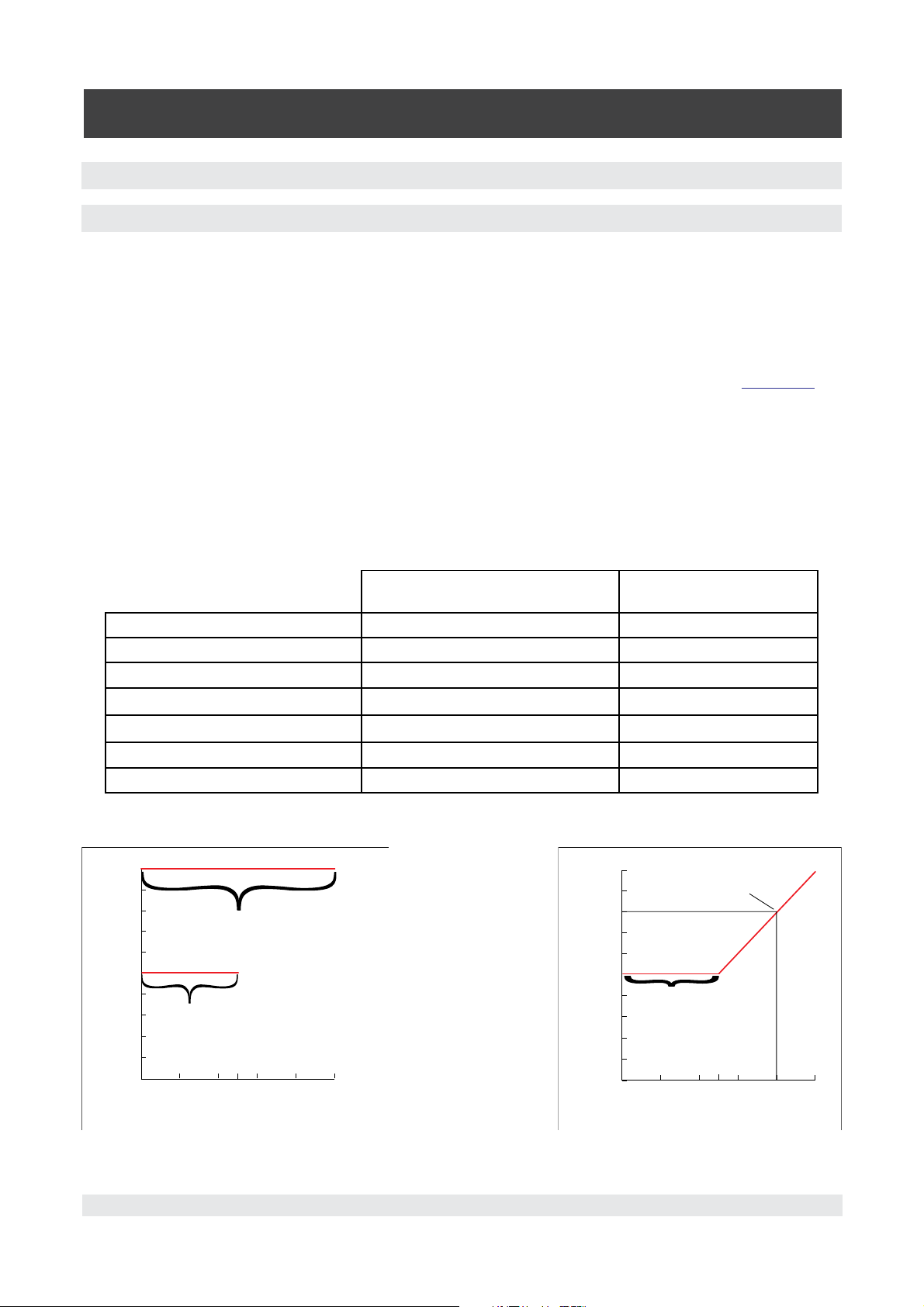
Below is an example showing the uncertainty of a “Turndown Transducer” and an “Intelliscale Transducer”.
0.010
0.009
0.008
Uncertainty of primary turndown
0.007
0.006
0.005
0.004
Uncertainty of secondary turndown
0.003
Uncertainty (psi)
0.002
0.001
0
0 20406080100
50
Pressure (psi)
100 psi sensor
Turndown Transducer, all software versions
0.010
0.009
0.008
0.007
0.006
0.005
0.004
0.003
Uncertainty (psi)
0.002
0.001
Intelliscale Transducers, Software >1.26
At 80 psi the uncertainty
is 0.01% of reading =
0.008 psi
At 50 psi and below
the uncertainty is
0.005% of full scale =
0.005 psi
0
0 20406080100
50
Pressure (psi)
100 psi sensor
Mensor/WIKA Operating Instructions - CPC 6000 13
Page 14

Automated Pressure Calibrator
CPC 6000
3.2 Features
Here is a short list of significant features designed into the CPC 6000:
1. 0.01%Intelliscale-
50 Uncertainty.
2. Up to four (two per channel) highly stable, temperature compensated, pressure transducers.
3. An optional internal high accuracy barometric reference transducer provides gauge pressure emula
tion for all of the absolute ranges and absolute pressure emulation for gauge ranges;
4. All pressure transducers are individually removable from the front of the CPC 6000 without the use
of tools (excluding the barometric transducer). This feature greatly facilitates “out of instrument”
recalibration of individual transducers using the optional Calibration Sled (see
Section 8, Options);
5. Two precision pressure regulators are selectable for controlled output pressure. These regulators
have a history of excellent control and stability;
6. A separate electrical module using a high speed microprocessor. The operating program is loaded
from a non-volatile flash disk;
7. A large color SVGA LCD display with a touch screen for intuitive operator interface;
8. Multiple languages; change the language for on-screen text and number/date formats instantly by
simply touching one of the “national flag” cues available on the display The current language selec
tions available are listed under ‘
6.3.2 - Flag Symbol ‘in Section 6, Local Operation.
Operate the CPC 6000 while it is either sitting on a bench or mounted in a standard equipment rack.
Leveling the instrument is not a consideration since the pressure sensors are not affected by orienta
tion. Use either front panel input (Local Operation), or send commands and queries over a bus from a
separate “host” controller (Remote Operation).
3.3 Front Panel
-
-
The CPC 6000 front panel (Figure 3.2) includes an 8.4 inch color SVGA display featuring touch screen
technology. Operator input is accomplished by pressing the words or symbols presented on the dis
-
play. There are no discrete keypads or switches on the front panel.
On the right hand side of the front panel, there is a clear window which shows the calibrated pressure
ranges of the internal transducers and the instrument serial number.
To gain access to the internal modules simply loosen the two thumb screws on the right hand edge of
the front panel and swing it open (Figure 3.3). In the front of the instrument directly below the electrical
module are slots to accommodate two pressure transducer modules on each control channel. Each
transducer can be removed and reinstalled through the front panel opening. See Section
9.3.1, Trans-
ducer Removal, for additional information on module removal and replacement.
Figure 3.2 - Front panel Figure 3.3 - Internal Access
14 Mensor/WIKA Operating Instructions - CPC 6000
Page 15
Automated Pressure Calibrator
CPC 6000
3.4 Display
When the CPC 6000 is powered up it takes about one minute for initialization, then displays a screen
similar to Figure 3.4. The display is made up of rectangles which display text or symbols.
Figure 3.4 - Terminology of Screen Elements
Keys, Tabs, Labels or Windows: In this manual a key is a small rectangle which acts as a switch
when pressed. Keys have borders with a three dimensional, shadowed effect. Tabs are a group of
touch points, each of which will overlay most of the screen with one page related to its title subject.
Labels or Windows are small rectangles with solid borders that display information, but do not re
-
spond to being touched.
Keys: Keys cause something to change when they are touched. Throughout this manual keys are
represented with the displayed characters enclosed in brackets such as [PSI A]. Each key has a char
acteristic response when actuated; either an instant, single step response when the key is pressed, or
continuously repeating steps while the key is held down, or a delayed response when released. Op
erators will quickly become accustomed to the particular characteristics of the frequently used keys.
Some keys become labels under certain conditions, then resume their key function in other circum
-
stances.
Header Bar: The bar across the top of the screen which displays the Mensor Logo, a title frame, and
a national flag is stationary and remains displayed at all times. All of the number formats and text dis
played on the CPC 6000 screens will be in the language appropriate to the national flag displayed here
such as American English for the USA flag, etc. Touch the flag to access a drop-down window show
ing all of the languages programmed into the CPC 6000 (see
6.3.2 - Flag Symbol). Touch any flag to
-
change the display to the corresponding language.
Mensor/WIKA Operating Instructions - CPC 6000 15
Page 16

Automated Pressure Calibrator
CPC 6000
Optional Display: The optional display is a window near the pressure label. This window can be set
up to be blank, or to display any one of the following:
■
Peak Pressure – minimum and maximum
■
Rate of change of a measured pressure
■
Barometer reading
Footer Keys: Like the top bar, the [Remote] and [Program] keys on the bottom left corner of the
display remain permanently on-screen. Touching either of these keys will cause that subject page to
appear in the display.
16 Mensor/WIKA Operating Instructions - CPC 6000
Page 17
Automated Pressure Calibrator
CPC 6000
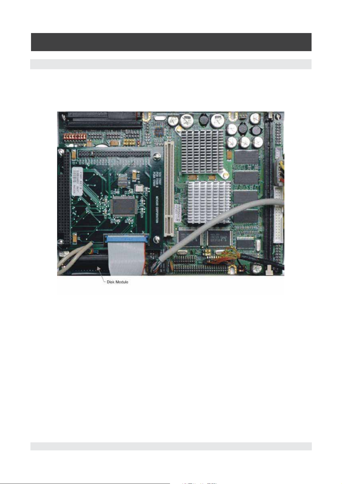
3.5 Electrical Module
The electrical module is illustrated below with the instrument lid removed (Figure 3.5). All program
information to run the system resides on a solid state disk module located on this module. The power
switch and line fuses are situated on the rear of the electrical module such that they are accessible on
the rear of the fully assembled CPC 6000.
Figure 3.5 - Electrical Module
Mensor/WIKA Operating Instructions - CPC 6000 17
Page 18
Automated Pressure Calibrator
CPC 6000
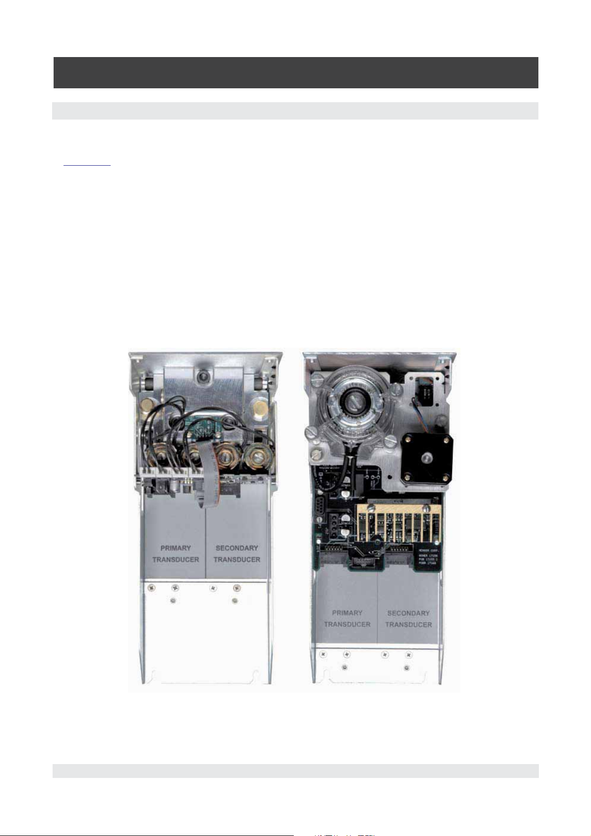
3.6 Pneumatic Module
Pneumatic modules come in two types and are referred to in this manual as the “Pump Regulator”
or the “Solenoid Valve Regulator”. The pump regulator is used with low pressure sensors specified
Section 4, Specifications. The solenoid valve regulator is used with higher pressure sensors and
in
comes in three varieties:
■
High Pressure Solenoid Valve Regulator (HP SVR)
■
Medium Pressure Solenoid Valve Regulator (MP SVR)
■
Low Pressure Solenoid Valve Regulator (LP SVR)
Pressure limits for all of these are specified in Section 4, Specifications.
Each pneumatic module (Figure 3.6) includes platforms for up to two high performance pressure trans
ducers which are traceable to NIST standards. Both of these transducers can be used in conjunction
with the highly stable pressure regulator to produce a precise pressure output. Each transducer in
cludes its own on-board compensation and calibration data so that any transducer can be replaced in
the instrument without requiring a recalibration.
-
Figure 3.6 - Pneumatic Module
18 Mensor/WIKA Operating Instructions - CPC 6000
Page 19
Automated Pressure Calibrator
CPC 6000
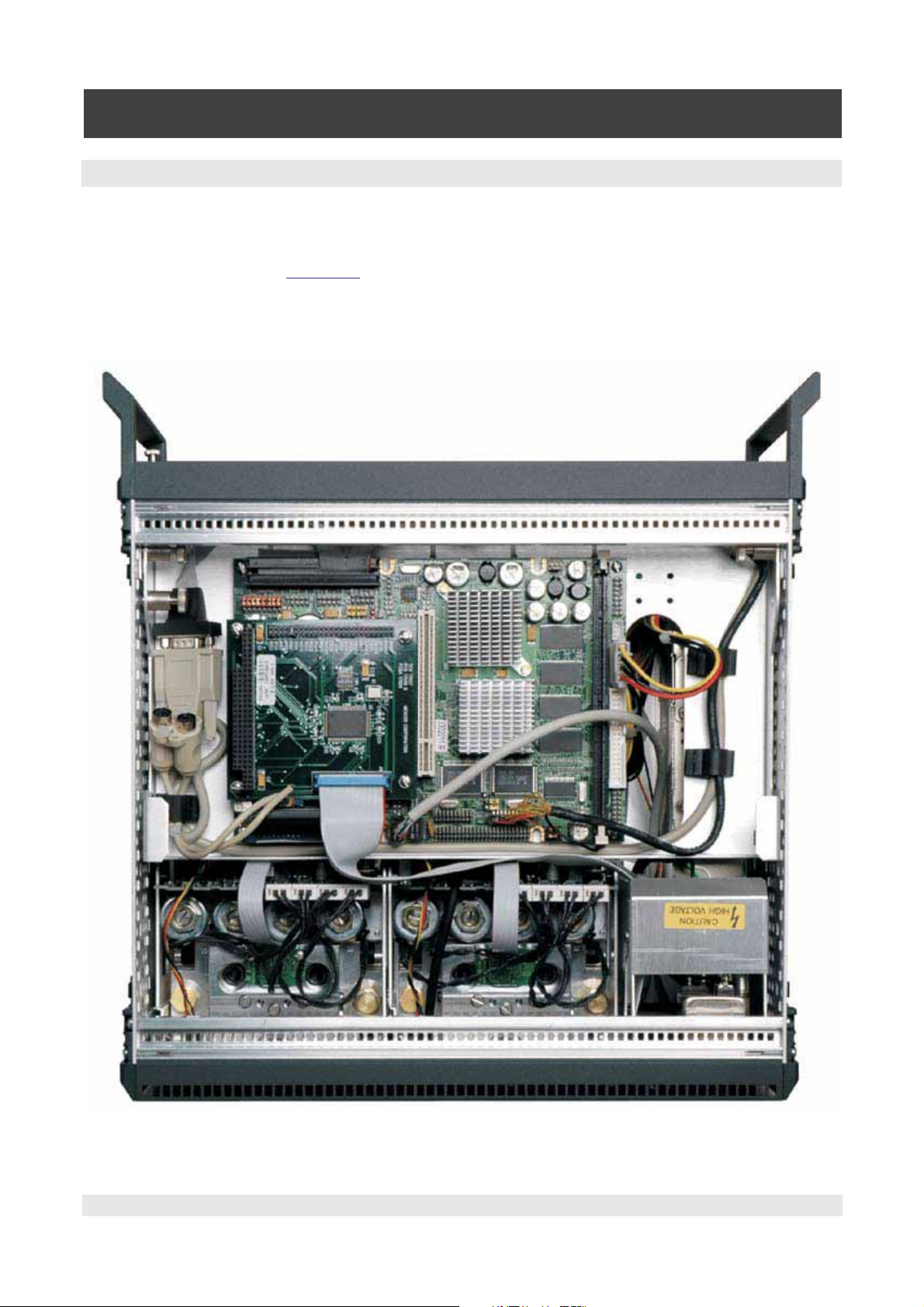
3.7 Chassis Assembly
The chassis assembly acts as the housing for the system. The electrical and pneumatic modules are
each self-contained inside the chassis, and either can be replaced using basic hand tools. In addition,
each pressure transducer is individually removable without tools. Instructions for transducer and mod
ule removal are provided in
The only moving parts in the CPC 6000 are the fan, the pneumatic flow controller diaphragms and
valves, the pump/motor, and the solenoid valve plungers. There are no internal user adjustments or
setup switches.
Section 9, Maintenance.
-
Figure 3.7 - Chassis Assembly
Mensor/WIKA Operating Instructions - CPC 6000 19
Page 20
Automated Pressure Calibrator
CPC 6000
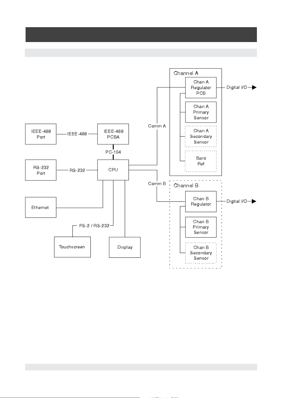
3.8 Electrical Block Diagram
Figure 3.8 - Electrical Block Diagram
20 Mensor/WIKA Operating Instructions - CPC 6000
Page 21

Automated Pressure Calibrator
CPC 6000
4. Specifications
Accuracy specifications presented herein are obtained by comparison with primary standards traceable to the National Institute of Standards and Technology (NIST). These specifications are obtained in
accordance with the ISO Guide to the Expression of Uncertainty in Measurement (GUM). Any excep
tion are noted on the individual calibration certificate.
Mensor reserves the right to change these specifications without notice.
4.1 Measure Specifications
Uncertainty 0.01%Intelliscale-50 (0.01%IS-50) provides 0.01% of
reading uncertainty from 50% to 100% of the full scale
value of the sensor and an uncertainty of 0.005% of
full scale from 0% to 50% of the full scale value of the
sensor. The 0.01%IScalibration interval. Uncertainties for these ranges are
denoted below as “0.01%IS-50 (365 days)” or Type
“IS”.
Ranges with uncertanties denoted below as “0.01%FS
(180 days)” or “0.01%FS (365 days) can have two
turndown ranges on the transducer. Each range has
0.01%FS uncertainty. The second turndown range
span cannot be less than 50% of the primary turn
down range span. The 0.01%FS specification has a
180 or 365 day calibration interval depending on the
range.
50 specification has a 365 day
-
-
Type
TD
IS
TD
TD
IS
TD
TD
TD
Uncertainties include all pressure effects, temperature
effects and calibration stability over 180 days after rezeroing.
Gauge
Transducer Range Interval (psig) Uncertainty (calibration stability)
0 ... 0.36 to 0 ... 14.9 0.01%FS (180 days)
0 ... 15 to 0 ... 1500 0.01%IS-50 (365 days)
0 ... 15 to 0 ... 1500 0.01%FS (365 days)
Absolute
Transducer Range Interval (psia) Uncertainty (calibration stability)
0 ... 5 to 0 ... 14.9 0.01%FS (180 days)
0 ... 15 to 0 ... 1515 0.01%IS-50 (365 days)
0 ... 15 to 0 ... 1515 0.01%FS (365 days)
Bi-Directional
Transducer Range Interval (psi) Uncertainty (calibration stability)
-0.18 ... +0.18 to -5 ... +14.9 0.01%FS (180 days)
-5 ... +15 to -15 ... +1500 0.01%FS (365 days)
Mensor/WIKA Operating Instructions - CPC 6000 21
Page 22

Automated Pressure Calibrator
CPC 6000
Pressure Ranges Specific ranges within the range intervals are selected
by the customer.
Optional Barometer Range 11 to 17 psia
Optional Barometer Uncertainty 0.01% of reading with a recommended calibration
interval of 365 days
Measurement Units
Resolution 4 to 7 significant digits, user selectable.
4.2 Control Specifications for the Pump Regulator Module
psi, inHg@0°C and 60°F, inH2O@4°C, 20°C and 60°F,
ftH2O@4°C, 20°C and 60°F, mTorr, inSW@0°C, ft
SW@0°C, mSW@0°C, ATM, bar, mbar, mmH2O@4°C
and 20°C, cmH2O@4°C and 20°C, MH2O@4°C,
mmH2O@0°C, cmHg@0°C, Torr, hPa, kPa, Pa, Mpa, D/
cm2, G/cm2, Kg/cm2, OSI, PSF, TSF, TSI, mHg@0°C,
%FS and 2 user-defined units. (See also “11.1 - Mea
surement Units Table” in
Section 11, Appendix).
-
External Pressure Requirements:
Source Requirements Fast Mode: 10% over range of highest pressure
transducer.
Slow Mode: None.
Note: The difference between the source pressure and
the minimum controlled pressure must be less than
30 psi. Performance can be enhanced with a well-
regulated source pressure.
Exhaust Requirements Fast Mode: A vacuum source is required for sub-at
mospheric pressure control.
Slow Mode: None
Stability of Controlled Pressure Fast and Slow Mode: 0.003% of span of active range,
typically better than 0.001% of span 10 seconds after
displaying stable flag.
Available Sensor Range Fast Mode: Absolute: 0 to 5 psia to 0 to 30 psia
Gauge: 0 to .36 psig to 0 to 15 psig
Bi-directional: -.18 to +.18 psi to -atm to 15 psig
Slow Mode: Absolute: 0 to 5 psia to 0 to 30 psia
Gauge: 0 to .36 psig to 0 to 15 psig.
Minimum Controlled Pressure Fast and Slow Mode: 0.05% FS or .05 psi over ex-
haust pressure, whichever is greater. The minimum
control point on absolute ranges is .5 psia.
Pressure Control Rates Fast Mode: Fast control mode uses the roughing
valves.
Slow Mode: Slow mode uses only the pump.
-
22 Mensor/WIKA Operating Instructions - CPC 6000
Page 23

Automated Pressure Calibrator
CPC 6000
Control Time Fast Mode: 10 seconds to stable flag for 10% FS step
pressure change into a 50cc volume. Larger volumes
can lengthen this time. Controlling to low absolute
pressures will lengthen this time.
Slow Mode: 15 seconds to stable flag for 10% FS step
pressure change into a 50cc volume. Larger volumes
can lengthen this time. Controlling to pressures less
than 0.5 psia will lengthen this time.
Supply Consumption Fast Mode: Zero after setpoint is reached. All supply
gas is used for upscale pressure sample filling.
Slow Mode: Zero
Measure to Control Offset Fast and Slow mode: <0.0005% Span
Overshoot <1% of active range.
4.3 Control Specifications for the Solenoid Valve Regulator Module
External Pressure Requirements:
Source Requirements 10% over range of highest pressure transducer or 20
psi over highest pressure transducer for a pressure
channel, whichever is less.
Exhaust Requirements A vacuum source is required for sub-atmospheric
pressure control.
Stability of Controlled Pressure 0.003% of span on active range. Typically better than
0.001% of span 10 seconds after displaying stable
flag.
Sensor Spans Available in each Regulator
Type
LP SVR: 0-1 psig to 0-50 psig (0-5 psia to 0-50 psia).
MP SVR: 0-10 psi to 0-150 psi.
HP SVR: 0-75 psi to 0-1500 psi.
Minimum Control Pressure 0.05% FS or .025 psi over exhaust pressure, which
-
ever is greater.
Control Time 10 seconds to stable flag for 10% pressure step
change into 50cc volume. Larger volumes can
lengthen this time. Controlling to pressures less than
0.5 psia can also lengthen this time.
Pressure Control Rates Slow, Medium, Fast, Max (default).
Supply Consumption <2.5 scfh in steady-state control.
Overshoot Low overshoot mode: <.005%
High speed mode: <1%
Mensor/WIKA Operating Instructions - CPC 6000 23
Page 24

Automated Pressure Calibrator
CPC 6000
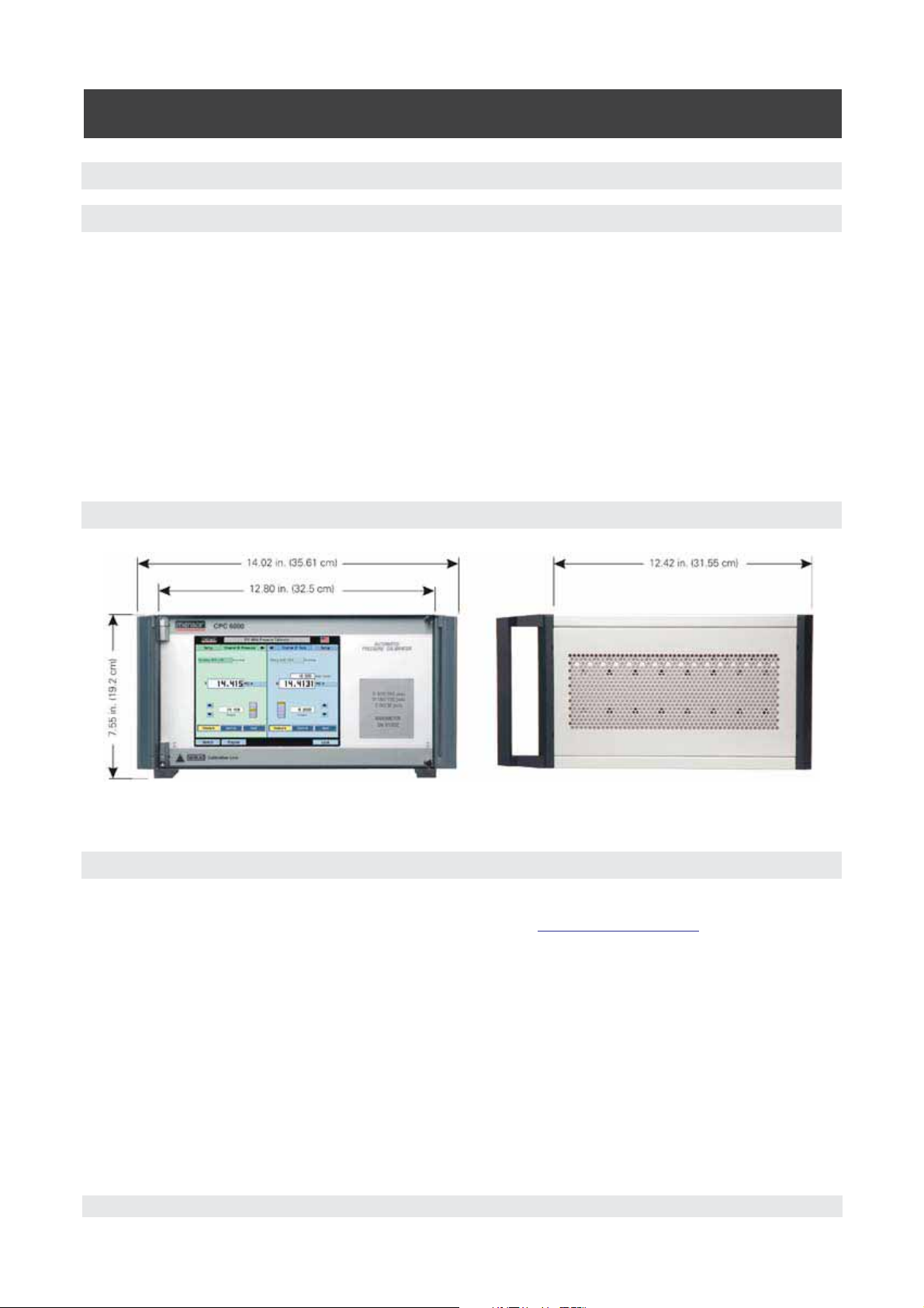
4.4 General Specifications
Size 14.02” wide x 7.55” high x 12.42” deep (35.61 cm x
19.2 cm x 31.55 cm). See Figure 5.2.
Weight 36 lbs. (16.33 kg) with all internal options.
Power Input Requirements 100-240 VAC, 47-63 Hz, 75 VA max.
Fuses: 1.5A, 230V, Type T LITTLEFUSE 31301.5
Digital I/O Pin 1: +5 VDC, 100 mA max.
Pin 2: Input TTL levels. Voltage input should be limited
to > -0.3 VDC and < +5.3 VDC.
Pin 3: Output pulled up to 5 VDC with a 10k ohm
resistor. Source limited to 450uA, Sink 10mA
Pin 4: Ground.
Pneumatic Interfaces 7/16” – 20 female SAE.
1/8” FNPT adapters provided.
Particle Filters The instrument has 20-micron filters on all pressure
ports through the manifold.
The barometric transducer has no filters.
Pneumatic Overpressure Protection Sensors are protected by relief valves.
Compensated Temperature Range 15°C to 45°C.
Operating Temperature Range 0°C to 50°C. Note: This is not the compensated
temperature range.
Storage Temperature Range 0°C to 70°C. Minimal vibration.
Non-condensing humidity.
Local User Interfaces 8.4” color LCD display with 8 wire resistive touch
screen.
Remote User Interfaces RS-232, Ethernet, and IEEE-488.1 are standard.
Warm-up Approximately 15 minutes to achieve full accuracy
depending on environment.
Reading Rate Typically 32 readings per second.
Measure Response Time <333 mS for FS step.
Orientation Effects Negligible, can be removed with re-zeroing.
Operating Environment 5 to 95% RH non-condensing.
Pressure Media Clean, dry, non-corrosive, non-combustible, non-
oxidizing gases. Not suitable for oxygen use.
Compliance
See section “1.3 Compliance”
Options Transport Case, Rack Mount Kit, Calibration Sled
Kit, Secondary Transducer, Barometric Reference
Transducer, Virtual Delta Channel
24 Mensor/WIKA Operating Instructions - CPC 6000
Page 25
Automated Pressure Calibrator
CPC 6000
5. Installation
5.1 Unpacking the System
In addition to this manual you should have:
■
CPC 6000 Automated Pressure Calibrator
■
Power cord
■
1/8 inch FNPT fitting adapters fastened to rear panel
■
Any accessories ordered
■
An envelope containing the Calibration Certificate
Your new instrument was subjected to many hours of functional testing before it left the factory. In
addition to testing, the unit was inspected for appearance prior to being packaged for shipment. Upon
removal from its carton please examine the instrument for shipping damage. Report any apparent
damage to the carrier immediately.
5.2 Dimensions
Figure 5.2 - Dimensions
5.3 Mounting
The instrument can be set up on a table top or it can be rack-mounted. Rack mount adapters are
optional on the CPC 6000 and require an adapter panel (see “
Options). The special sensors used in the CPC 6000 are relatively insensitive to tilt and vibration.
However to further assure stability and accuracy, avoid mounting the instrument on surfaces subject
to excessive motor or machinery vibration.
Mensor/WIKA Operating Instructions - CPC 6000 25
8.2 - Rack Mount Kit” in Section 8,
Page 26
Automated Pressure Calibrator
CPC 6000
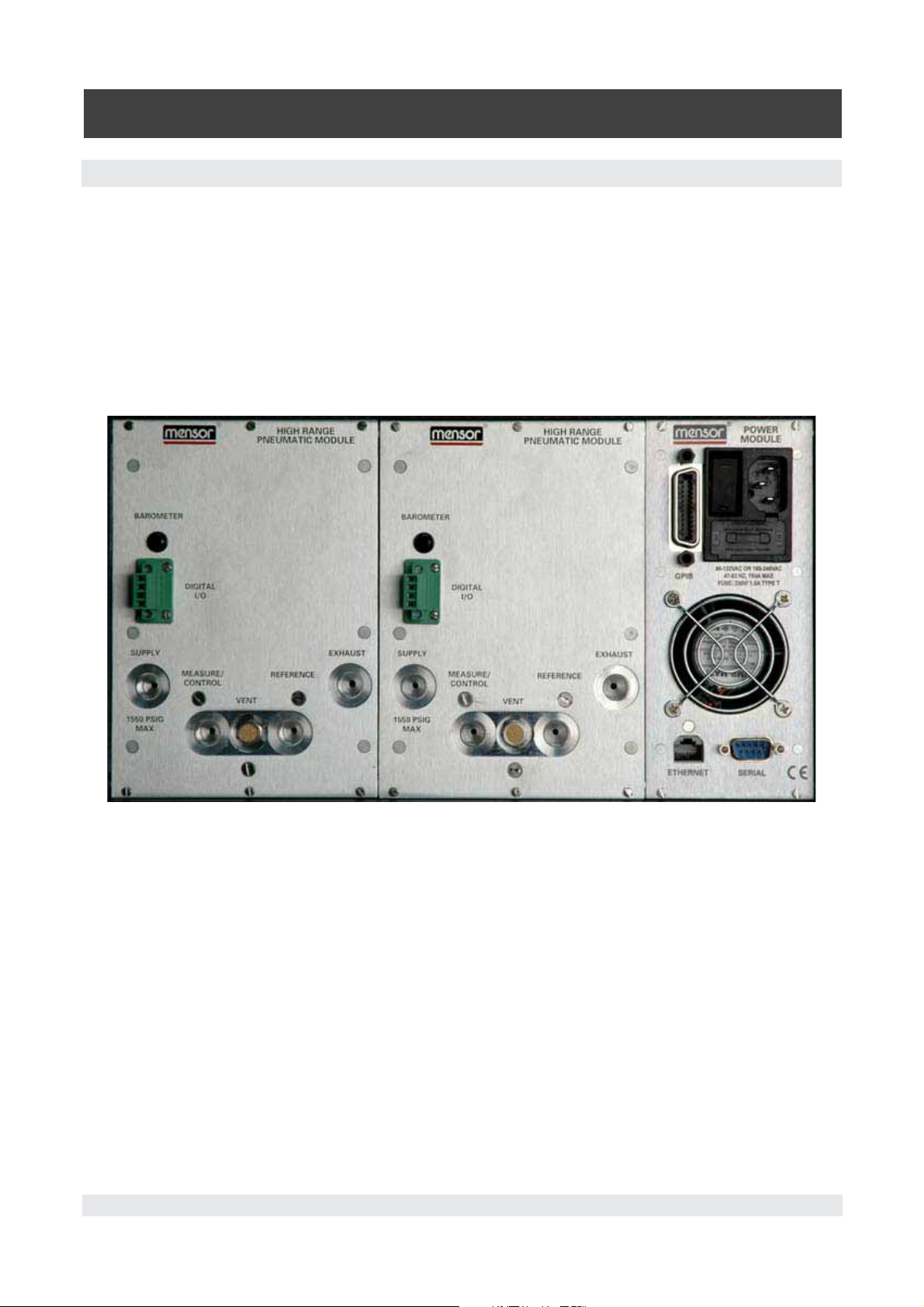
5.4 Rear Panel
Up to eight pneumatic pressure ports are located horizontally across the rear panel (Figure 5.4). Po
sitioned to the right of the pressure ports are the Ethernet, RS-232 and GPIB connector, the off/on
switch, the line fuses, and a protective grill covering the ventilating fan.
Figure 5.4 shows a rear panel containing two solenoid valve regulator pneumatic modules. Rear panels
may differ depending on what modules are installed.
Figure 5.4 - Rear Panel
26 Mensor/WIKA Operating Instructions - CPC 6000
Page 27

Automated Pressure Calibrator
CPC 6000
5.5 Pressure Connections
When making up a connection to an o-ring adapter port use a back-up wrench to
i
i
Notice
Notice
All of the pressure ports on the rear are female 7/16 - 20 SAE/MS straight threads per MS16142 and
SAE J514 table 14. They require a tube fitting boss seal with an o-ring per MS33656. Mensor provides
female 1/8” NPT adapter fittings with the instrument. The pressure connections can be made to these
adapters with the proper mating hardware. We recommend the use of either Loctite® Hydraulic Seal
ant or new teflon tape on the threads of any male pipe fitting. Do not use sealant on fittings sealed
with an o-ring. The integrity of each seal is particularly important since even microscopic leaks can
cause errors in pressure measurements. The rear panel connections and a complete pneumatic sche
matic, including the optional secondary transducer, are provided in the
Figures 9.2.1C and 9.2.2B). Requirements for connecting to the ports on the CPC 6000 manifold are
as follows:
5.5.1 Supply Port
prevent over-stressing the threads in the manifold block.
-
Maintenance Section (see
-
Connect a source pressure to the SUPPLY port of each channel. See “Source Pressure” in
Specifications, for supply pressure requirements for various pressure ranges.
CAUTION: The control channels are completely independent. Separate supply
pressures should be applied to the control channels based on the maximum
!
Caution
i
i
Notice
Notice
5.5.2 Measure/Control Port
Connect a device to be tested to the MEASURE/CONTROL port. In MEASURE mode the CPC 6000
will precisely measure the pressure at this port.
A pressure value can be selected using the on-screen keypad. That pressure will then be output to the
MEASURE/CONTROL port by switching to the CONTROL mode of operation.
!
!
Warning
Warning
pressure range of each channel. Applying source pressure higher than the
recommended pressure can cause permanent damage to the control channel.
Performance can be enhanced with a well-regulated source pressure.
WARNING: HIGH NOISE LEVELS! As pressure decreases compressed gas will
escape out the exhaust port. For ranges above 600 psi high noise levels may result
during such pressure releases. To overcome objectionable exhaust noise either
install a muffler or route the port to a remote location.
Section 4,
CAUTION: Improper use of this equipment may impair protection provided by this
!
!
Caution
Caution
Mensor/WIKA Operating Instructions - CPC 6000 27
instrument.
Page 28
Automated Pressure Calibrator
CPC 6000
5.5.3 Exhaust Port
If sub-atmospheric control pressure is required a vacuum pump must be connected to the EXHAUST
port. Otherwise, this port may be left open to atmosphere.
5.5.4 Reference Port
On gauge units this port is connected to the reference side of the transducer, and on absolute units it
is internally capped. This port is normally left open to atmosphere but may be attached to a snubber
assembly on very low pressure instruments.
5.5.5 Remote Bus Connections
Section 7, Remote Operation, for connections and commands for operation over ethernet, RS-
See
232 serial port or IEEE-488.
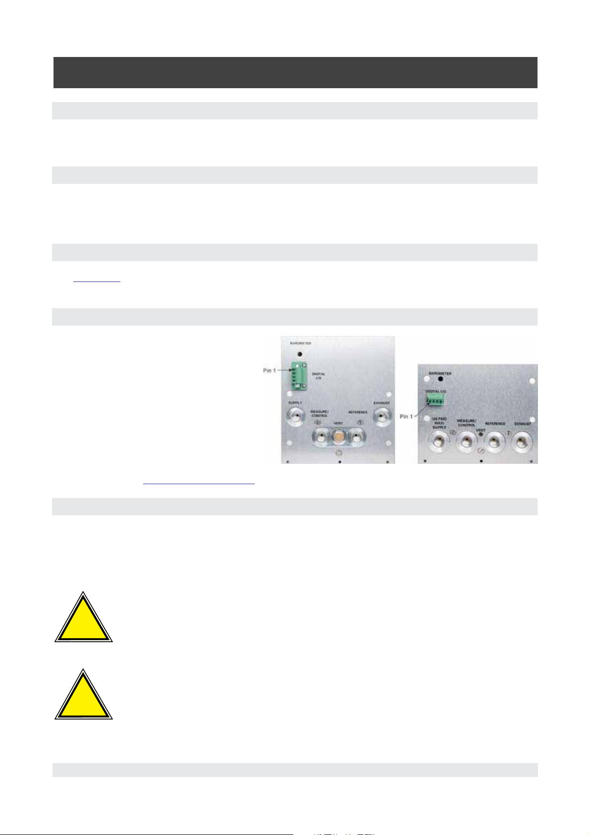
5.5.6 Digital I/O Connection
The Digital I/O connection consists of four
pins.
Pin 1: +5 VDC
Pin 2: Input TTL levels. Voltage input
should be limited to > -0.3 VDC
and < +5.3 VDC.
Pin 3: Output, pulled up to 5V with a
10k ohm resistor. Source limited to
450uA, Sink 10mA.
Pin 4: Ground
(See ‘Digital I/O’ in
5.6 Turning on the CPC 6000
After the pressure connections are secure, apply power to the power connector on the rear of the
instrument and switch the power switch ON. The instrument will go through an initialization process
and system check. As soon as the system check is completed the system will default to an operating
screen similar to Figure 6.3B. Allow at least 15 minutes of warm up before performing critical pressure
measurements.
!
!
Warning
Warning
Specifications section. Figure 5.5.6 - Digital I/O Connection
WARNING: EARTH GROUND! Any power adaptors or surge protection devices that
negate the protective earth ground should not be used.
The power cord is the disconnection device and its outlet should be accessible and
contain a protective earth ground.
!
!
Warning
Warning
28 Mensor/WIKA Operating Instructions - CPC 6000
WARNING: VENTILATION! Do not block airflow to ventilating fan located on rear of
instrument.
Page 29
Automated Pressure Calibrator
CPC 6000
6. Local Operation
6.1 General
This section describes the procedures for operating the CPC 6000 from the front panel. Instructions
for operating the device remotely from an external computer are covered in the next section,
operation
you can expect your CPC 6000 to deliver maximum accuracy and dependability for many years of
useful service.
6.2 Keys and Tabs
Local operation is accomplished by observing the data presented in the display, then pressing the
on-screen [key] or [tab] for the desired function. Throughout this manual characters enclosed inside
square brackets[]represent the associated on-screen touch point.
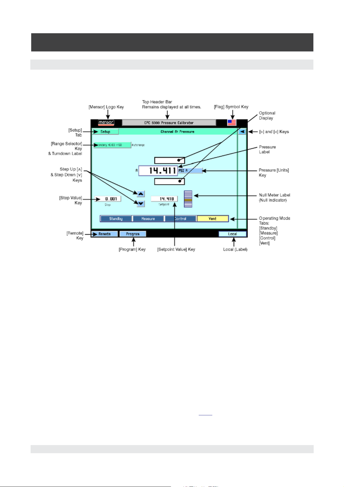
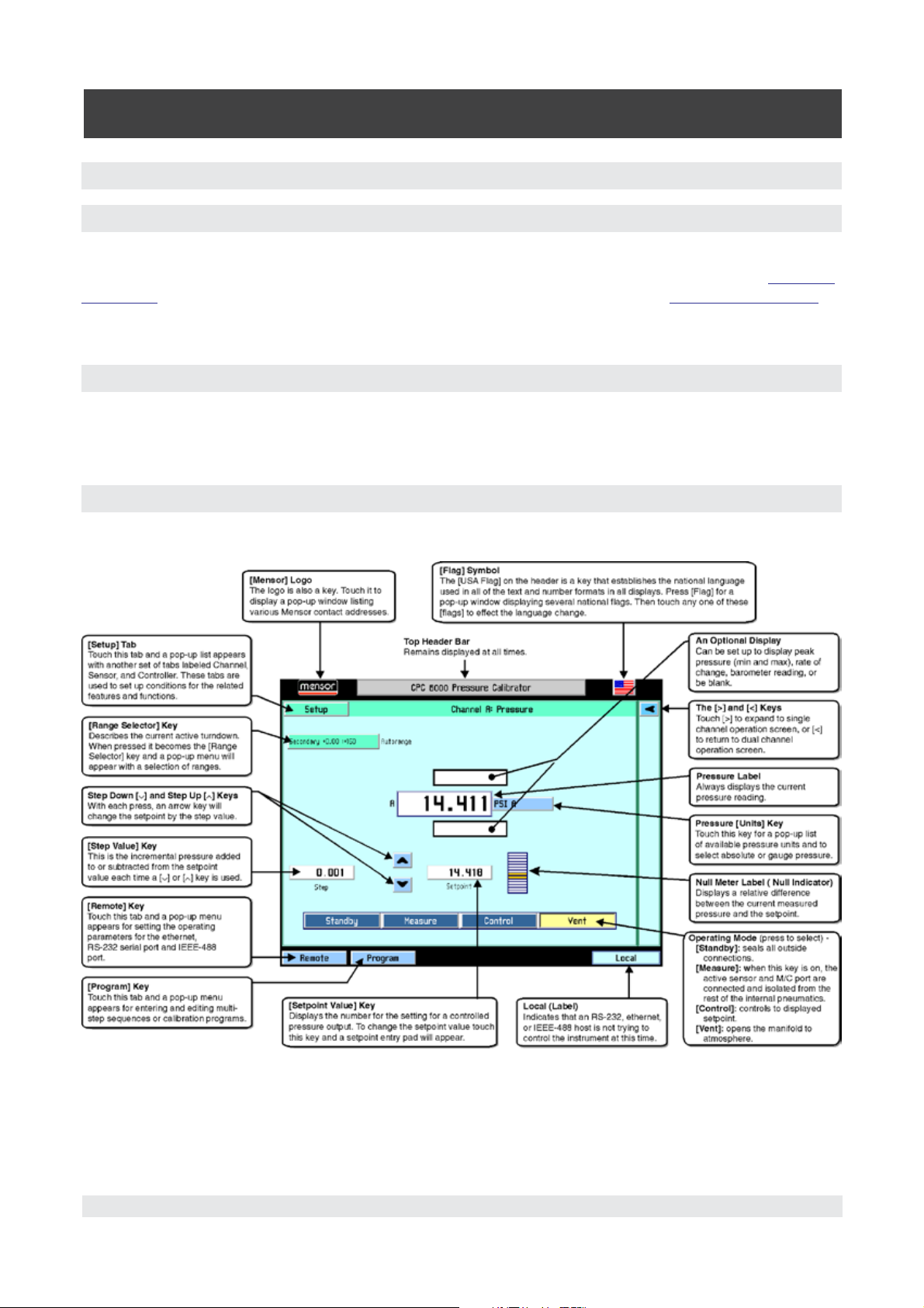
6.3 Display Screen Features
Figure 6.3A provides a brief description of the features shown on a single channel display.
. By following the procedures provided in these two sections and the Calibration section,
Remote
Figure 6.3A - Display Screen Features
Mensor/WIKA Operating Instructions - CPC 6000 29
Page 30
Automated Pressure Calibrator
CPC 6000
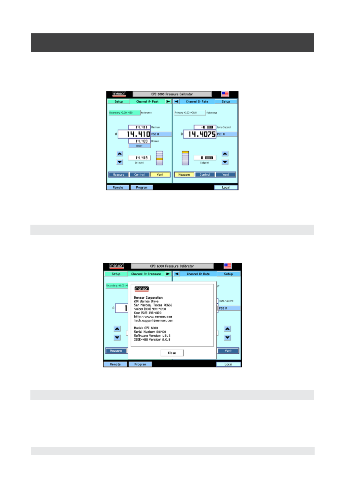
Figure 6.3B is an example of a typical display after initialization. To expand the selected channel to a
single channel operation screen as shown in Figure 6.3A, press the [>] key. The [Standby] key appears
on the screen when expanded. To expand or return to a dual channel operation screen press the [<] or
[>] key.
Figure 6.3B - Typical Operation Screen
All of the CPC 6000 screen features are described in more detail in the rest of this section.
6.3.1 [Mensor] Logo
The logo is also a key. Touch it to display a pop-up window as shown in Figure 6.3.1 listing various
Mensor contact addresses and CPC 6000 serial number and version information. Touch [Close] to
close the window.
Figure 6.3.1 Mensor Address/Contact Information Window
6.3.2 [Flag] Symbol
The [USA Flag] on the header is a key that establishes the national language used in all of the text and
number formats in all displays. Press the [Flag] for a pop-up window displaying several national flags
(Figure 6.3.2). Touch any one of these [Flags] to effect the language change.
30 Mensor/WIKA Operating Instructions - CPC 6000
Page 31

The current language selections available are:
Language Country
English USA
German Germany
German Switzerland
English Great Britain
Chinese China
English Canada
French France
French Switzerland
English Ireland
Korean Korea
French Canada
Italian Italy
Russian Russia
Polish Poland
Japanese Japan
Spanish Mexico
Spanish Spain
i
i
Notice
Notice
Automated Pressure Calibrator
CPC 6000
Figure 6.3.2 - Language Selection WindowFigure 6.3.2 - Language Selection Window
The language selection acts on the screen
The language selection acts on the screen
displays only, and does NOT affect remote
displays only, and does NOT affect remote
commands and responses. All remote dialogs
commands and responses. All remote dialogs
listed in
listed in
literal as described.
literal as described.
Section 7, Remote Operation, are
Section 7, Remote Operation, are
6.3.3 [>] and [<] Keys
The [>] and [<] keys will expand the selected channel to single channel operation
screen, or return to dual channel operation screen.
6.3.4 Turndown Label and [Range Selector] Key
The label in the upper left portion of Figure 6.3.4A describes the current active range as “Secondary
+0.00 :+160”. This may be the full scale range of an Intelliscale transducer or a range in a Turndown
Transducer. The label , when touched, becomes the [Range Selector] key. Different colors are used to
distinguish primary and secondary transducers. The currently active range is highlighted with a yellow
background. Touch any range other than the yellow one to select a different range as shown in Figure
6.3.4B. The last selection in this range selector is [Autorange], which will automatically switch to the
most accurate range in the system capable of measuring the current pressure. Each change is imme
diately reflected in the turndown label. There is also a label beside the current active range to show if
you are in range hold or autorange. Intelliscale Transducers and Turndown Transducers can be used
simultaneously within the same channel. See
description of Intelliscale Transducers and Turndown Transducers.
Section 3.1 “General Description” for a more detailed
-
Mensor/WIKA Operating Instructions - CPC 6000 31
Page 32

Automated Pressure Calibrator
CPC 6000
Some pressure units can cause a number to be too long for the value window. In
those cases the value will be abbreviated with an “m” (milli), “k” (kilo), or “M”
i
i
Notice
Notice
An important feature of the CPC 6000 is that transducers can easily be changed. A transducer can be
replaced in the CPC 6000 in less than 30 seconds, with no tools required. Each installed transducer
identifies itself to the system using its on-board stored data. Among the items stored in this data are
the transducer serial number, curve characterizations and calibrations for each turndown, the dates of
calibration, and the transducer’s software version.
i
i
Notice
Notice
(mega) multiplier appended to the range in the range drop list.
There is no alarm or signal that a transducer has been removed or exchanged. If
security is an issue, a visible seal or calibration sticker might be placed on the
front panel in such a manner that it must be broken to gain access to the transducers.
Figure 6.3.4A - [Turndown Label] Figure 6.3.4B - [Range Selector] drop-down menu
6.3.5 Pressure Label
Below the turndown label shown in Figure 6.3.4A is a larger label showing the measured pressure
value of “14.410”. This large label always displays the current pressure reading.
6.3.6 Pressure [Units] Key
To the right of the pressure label is the [Units] key, shown in Figure 6.3.4A as [PSI]. Touch [PSI] and a
pop-up menu of pressure units will appear as in Figure 6.3.6. This menu includes [User 1] and [User
2] keys allowing the user to enter customized pressure units. Touch [PSI] and it will toggle to Pascal.
Press a [Value] key to enter a custom multiplier to equal either one PSI, or one Pascal, whichever is
showing in the user multiplier base units key.
The upper right [absolute] or [gauge] key allows emulation mode if an optional barometric sensor is
installed. See
32 Mensor/WIKA Operating Instructions - CPC 6000
Section 8, Options.
Page 33

Automated Pressure Calibrator
CPC 6000
The current units are highlighted by a yellow background. Touch any other [Pressure Units] key, and
press [OK] to enable change and return to previous operation screen. All of the displayed pressure
values will have changed to correspond to the newly selected units at the correct conversion ratio.
Figure 6.3.6 - Units Selection Window
6.3.7 [Step Value] Key
On the left side of the screen as seen in Figure 6.3A is the [Step Value] key. The step value displayed
is 0.001. This is the incremental pressure added to or subtracted from the setpoint value each time a
[@or [] key is used on the main screen. To change the step value touch the [Step Value] key and the
step entry pad as shown in Figure 6.3.7 will appear.
This number pad shows the maximum and minimum values applicable to the active turndown. There is
also a Current Value and a New Value window. Enter a new step number and then press [OK], or else
touch [Cancel] to return to the operate screen without changing the step value. Press CE to back
-
space.
Figure 6.3.7 - Step Value Window (Single Channel)
Mensor/WIKA Operating Instructions - CPC 6000 33
Page 34

Automated Pressure Calibrator
CPC 6000
6.3.8 Step Down [] and Step Up [] Keys
As shown in Figure 6.3A, the [
the [Setpoint Value] key; one for Step Down [
] and [] keys are located to the side (different for A and B Channels) of
], and another for Step Up []. Pressing an arrow key will
change the setpoint by the step value until the control limits of the channel are reached.
6.3.9 Control Pressure [Setpoint Value]
The number displayed inside the [Setpoint Value] key is the setting for a controlled pressure output.
When the [Control] key at the bottom of the active channel screen is switched to [On] the regulator will
attempt to present that precise pressure to the Measure/Control port on the rear panel. The setpoint
number is changed either by using the [
] and [] keys, or by touching the [Setpoint Value] key to input
a new number.
If the displayed number is beyond the range of a selected turndown in range hold mode, the number
will change to a control value within the limits of the turndown. The setpoint will change in value auto
matically, but it will not be restored automatically if the previous turndown is reselected.
[Standby] key: When this key is ON all internal solenoid valves are closed.
[Measure] key: When this key is ON the active sensor and the Measure/Control port are connected
and isolated from the rest of the internal pneumatics.
[Control] key: When this key is ON the unit will attempt to control to the setpoint displayed.
-
[Vent] key: When this key is ON the internal pneumatics are open to atmosphere.
Figure 6.3.9 - [Setpoint Value] Window
34 Mensor/WIKA Operating Instructions - CPC 6000
Page 35

6.4 [Program] Key
Automated Pressure Calibrator
CPC 6000
The [Program] key on the bottom left of the operation screen (see Figure 6.3B) enters the main pro
gram creation/edit screen shown in Figure 6.4A. Programmed multi-step sequences can be entered
and edited from this screen. There are sample programs available in the instrument that can be edited
and renamed. A saved program can be executed by entering the setup channel screen and selecting
the [Program] key. The CPC 6000 can store up to 64 programs with up to 100 steps in each program.
Figure 6.4A - Main Program Screen
The large key at the top of this screen contains the program name of the currently active program that
can be run or edited. If this key is pressed, a list of saved programs will be displayed as shown in Fig
ure 6.4B. The up and down arrow keys display additional pages of programs. To select a program to
run or edit, simply press the name of the program.
-
To create a new program sequence, select a blank line and press [OK]. To copy an existing program,
select the program to be copied, press [Copy], select a new line (or an existing program to overwrite)
and press [Paste]. The [Delete] key erases a program from memory.
Figure 6.4B - Program Selection Screen
Mensor/WIKA Operating Instructions - CPC 6000 35
Page 36

Automated Pressure Calibrator
CPC 6000
6.4.1 Editing or Creating a Program
To edit or create a program, select a program name from the Program Selection Screen and press
[OK]. This brings up the main program screen. Below the [Name] key is a table that shows a synopsis
of the program steps. There are also up and down arrow keys to display additional pages of program
steps.
To edit the selected program press the [Edit] key. This displays the program editing screen shown in
Figure 6.4.1A.
Figure 6.4.1A - Program Editing Screen
Each program line shown in Figure 6.4.1A only executes one function or command. Each line has an
index number associated with it. For example, if a program has 30 commands, the first command
index is 1:30 to represent that it is command one of 30 to be executed.
To edit individual program lines, select the index number of the program line to edit.
[Insert] key: inserts a new program line before the selected one. This also re-scales the index numbers accordingly.
[Delete] key: deletes the selected program line and re-scales the index numbers accordingly.
[Change] key: displays the program line edit screen as shown in Figure 6.4.1C . Its functionality is
described in the following text.
[Copy] key: copies the selected program line.
[Paste] key: To paste a copied program line over an existing line, select the program line to be over-
written and press the [Paste] key.
[Save] key: saves the individual program lines to the program and the program to memory. If program
lines are edited and the main program screen is exited without pressing the [Save] key, a warning dia
log box is displayed prompting the user to save program changes or cancel.
-
36 Mensor/WIKA Operating Instructions - CPC 6000
Page 37

Automated Pressure Calibrator
CPC 6000
To change the name of the program, press the [Name] key. This displays a keyboard screen shown in
Figure 6.4.1B. Enter the name of the program and press [OK] to return to edit the program steps.
Figure 6.4.1B - Keyboard Screen
The Program Line Edit Screen (Figure 6.4.1C) sets the function of each program line. Each program
line performs the function selected from the ones displayed in the left-most column.
Figure 6.4.1C - Program Line Edit Screen
[Sensor] key: This key selects which sensor and turndown to use for the program.
[Mode] key: The [Mode] key selects the operation mode of the CPC 6000.
[Units] key: This key selects the pressure units.
[Setpoint] key: This key allows the control pressure to be set with the key just to its right. Because of
the flexibility of the CPC 6000, it should be noted that to make the CPC 6000 control at this setpoint
there needs to be another program line that puts the CPC 6000 into the control mode.
Mensor/WIKA Operating Instructions - CPC 6000 37
Page 38

Automated Pressure Calibrator
CPC 6000
[Setpoint%] key: The [Setpoint%] key sets the control pressure at the entered percentage of the
range of the currently active transducer.
[Delay] key: The [Delay] key delays the execution of the program for the entered number of seconds.
[Wait] key: The [Wait] key delays the execution of the program until the instrument measures a stable
pressure, or the control pressure stabilizes within the control parameters or pauses until the operator
presses a key to continue the program execution.
[Start] key: The [Start] key causes execution of the program to begin at the first program line. This
is useful for running a program repeatedly until the stop key (the key with the black filled square) is
pressed by the operator.
6.4.2 Running a Program
To run a stored program, select the program mode from the channel setup screen (see “6.6.1 - [Chan
-
nel] Setup”). The main operation screen looks like Figure 6.4.2.
Figure 6.4.2 - Main Operating Screen in Program Mode
At the bottom of the screen, the function tabs (Measure, Control and Vent) are replaced by information
and tabs pertaining to the selected program. The large key at the top of this section is the program
name. Any saved program may be selected directly from this screen by pressing this key and selecting
the program to run.
When a program has been selected, the line below the program name key shows the current program
line that is or will be executed. The rightmost box on this line shows the time at which the program has
been on the current program line.
The five keys below this control the operation of the program.
The [<<] key steps one command line back.
The [>>] key steps one command line forward.
38 Mensor/WIKA Operating Instructions - CPC 6000
Page 39

Automated Pressure Calibrator
CPC 6000
The [>] key begins execution of the program at the first program line. It is also used to re-start a program at the current line after a wait/pause program line.
The next key shows a black square. Pressing this key stops execution of the program and resets the
program to the first program line.
The [II] key pauses program execution at the current program line. If the [>] key is subsequently
pressed, the program begins execution at the next program line.
6.5 [Local] Label
On the bottom right of the operation screen (Figure 6.3B) is a ‘Local’ label to indicate that an RS-232,
ethernet, or IEEE-488 host is not trying to control the instrument at this time. The text of this label will
change to “Serial”, the IP address of the controller, or “GPIB” when the CPC 6000 receives a remote
command.
6.6 [Setup] Key
Touch the [Setup] tab on the top left or top right corner of the Operation screen (Figure 6.3B) and a
new display appears with another set of tabs across the top as shown in Figure 6.6.1A. These tabs are
labeled [Channel], [Sensor], and [Controller]. The tab and screen that was last accessed is active by
default. The top tabs are used to set up conditions for the related feature/ function as explained in the
following text.
6.6.1 [Channel] Setup
Press the [Channel] tab to access the Channel Setup page as shown in Figure 6.6.1A. From there the
user can select the optional display function to be [Pressure], which will show only the current reading,
or have it show [Peak], [Rate], or [Barometer] readings.
Figure 6.6.1A - Channel Setup Screen
Mensor/WIKA Operating Instructions - CPC 6000 39
Page 40

Automated Pressure Calibrator
CPC 6000
The content of the three active displays are:
[Pressure]: Shows no alternate readings on the screen, only the measured pressure reading.
[Peak]: Displays the highest and lowest pressure points since the last [Reset], or power up. Figure
6.3B shows an example of the Peak feature displayed in this window.
[Rate]: Reports the rate at which the measured pressure is changing in units/second.
[Barometer]: If this optional feature was ordered with your CPC 6000, press this key to display the
atmospheric pressure reading.
[Normal] (mode selection): This mode will allow the user to command the instrument to individual
setpoints manually or remotely.
[Program] (mode selection): This mode will allow the user to define and run user entered program
sequences (Figure 6.4B).
[Default]: Touch this key to immediately reset the instrument to the following conditions:
■
Autorange ON; a solenoid valve regulator module defaults to low overshoot mode (see 6.6.2 “[Sen
sor] Setup”).
■
Step value: Ignore if valid; Set to 1 if out of range
■
Setpoint: Ignore if valid; Set to 0 if out of range
■
Restart peak maximum and peak minimum
■
Set sensor filter to Normal
■
Set control rate to Maximum
■
Set maximum allowable control point to match the highest maximum turndown in the instrument
■
Set minimum allowable control point equal the lowest minimum turndown in the instrument
■
Set the stable window to 0.003% FS
■
Set the stable delay to 4 seconds.
■
Any existing conditions not covered above will be unaffected.
[Status]: Touch this key to display all current channel information including: Model, Software Version,
Serial Number, Range, and Units. See Figure 6.6.1B.
-
Figure 6.6.1B - Status Screen
40 Mensor/WIKA Operating Instructions - CPC 6000
Page 41

Automated Pressure Calibrator
CPC 6000
6.6.2 [Sensor] Setup
Touch the [Sensor] tab and Figure 6.6.2A will appear.
Figure 6.6.2A - Sensor Setup Screen
Filter: The Filter is an electronic filter to smooth out the pressure readings. Because of the differences
in resolution, more filtering may display a more stable reading for some pressure units. Select the best
filter for the current units. [Off], [Low], [Normal], [High].
Resolution: The Resolution [value] key allows the user to enter the number of significant digits that will
be displayed on the operate screen. See Figure 6.6.2B.
Figure 6.6.2B - Resolution Window
[Calibrate] Setup key: Details for the [Calibrate] key are given in
Section 10, Calibration.
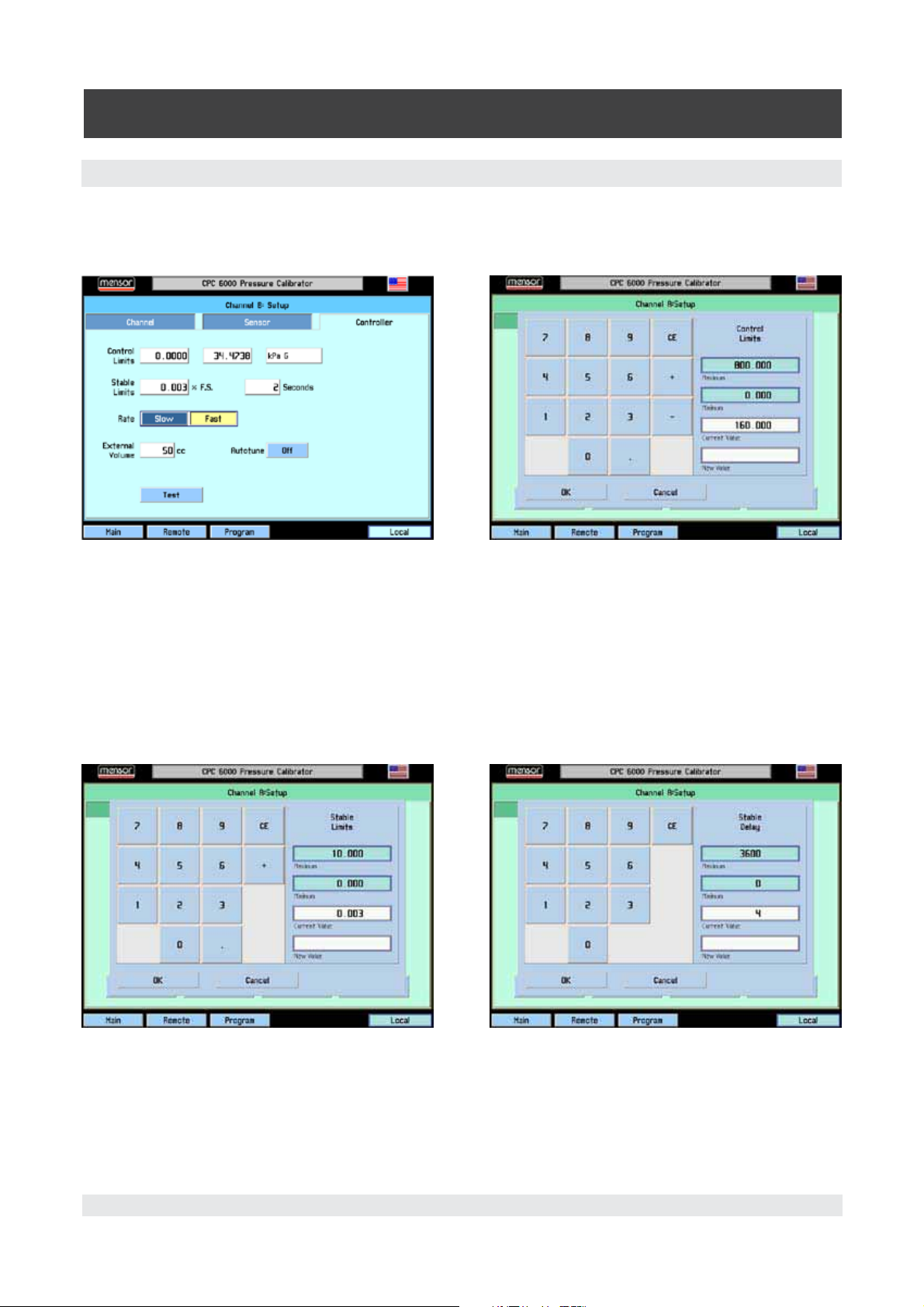
6.6.3 [Controller] Setup
The controller setup screen (Figure 6.7.1A for the pump regulator or Figure 6.8 for the solenoid valve
regulator) is used to set the control parameters for the selected pressure control channel.
The controller test screens are an interactive diagnostic display used for troubleshooting the overall
pneumatic system of the CPC 6000. Proper use of these features are described in
Section 9, Mainte-
nance.
Mensor/WIKA Operating Instructions - CPC 6000 41
Page 42
Automated Pressure Calibrator
CPC 6000
6.7 Pump Regulator
Control Limits: The control limits cannot be set outside the maximum or minimum ranges of the
transducers installed on the active channel. To change a limit touch either of the [Limit Value] keys and
enter the new value.
Figure 6.7.1A - Controller Setup, Pump Regulator Figure 6.7.1B - Control Limits Window
Stable Limits: The stable limit is the percent of span of the active range that the current pressure can
deviate from the setpoint and still display a stable flag.
To change the stable limit or stable delay press the appropriate key. The pop-up number pad will show
the upper and lower limits for the item being edited.
Stable Delay: The stable delay is the number of seconds that the instrument must remain within the
stable window before the stable flag is displayed.
Figure 6.7.1C - Stable Limit Window Figure 6.7.1D - Stable Delay Window
42 Mensor/WIKA Operating Instructions - CPC 6000
Page 43

Automated Pressure Calibrator
CPC 6000
Rate: A rate (slewing speed) which best suits the user’s test requirements is selected here. The [Slow]
rate will use internal pressure generation without the use of the roughing supply and exhaust valves.
Use this mode if no external supply or exhaust pressures are applied to the selected pressure control
channel. The [Fast] rate utilizes the roughing supply and exhaust valves.
External Volume: If the autotune is turned on, the external volume of the controlled system is calculated automatically for optimum control performance. If the external volume is known, the user can
press the external volume key and enter the volume. Subsequently, if [Autotune] is turned off, the
control channel will not re-calculate the external volume on each control setpoint change which will
decrease the control times.
Autotune: If the autotune key is turned on, the control channel automatically calculates the external
system volume for optimum performance on each control setpoint change.
[Test] key: is used to enter a test mode that gives the user individual control of all solenoids. This is
further described in
6.8 Solenoid Valve Regulator
Control Limits: The control limits cannot be set outside the maximum or minimum ranges of the
transducers installed on the active channel. To change a limit touch either of the [Limit Value] keys and
enter the new value.
Section 9, Maintenance.
Figure 6.8 - Controller Setup, Solenoid Valve Regulator
Stable Limits: The stable limit is the percent of span of the active range that the instrument can deviate from the setpoint and still display a stable flag. To change the stable limit or stable delay press
the appropriate key. The pop-up number pad will show the upper and lower limits for the item being
edited.
Stable Delay: The stable delay is the number of seconds that the instrument must remain within the
stable window before the stable flag is displayed.
Mensor/WIKA Operating Instructions - CPC 6000 43
Page 44

Automated Pressure Calibrator
CPC 6000
Rate: A rate (slewing speed) which best suits the user’s test requirements are selected here. The rates
vary the pressure slew rate while driving to a pressure setpoint. The [Slow] rate will target approxi
mately .1% of the highest installed range/second. The [Medium] rate will target approximately 1% of
the highest installed range/second. The [Fast] rate will target approximately 10% of the highest in
stalled range/second.
Variable rate allows the customer to enter the desired rate that the controller will approximate in the
current units/second.
Low Overshoot check: If this is checked, the control channel will minimize pressure overshoot when
driving to a new control setpoint.
Reference Vacuum check: ONLY AVAILABLE ON GAUGE UNITS! If checked, customers may pump
the reference port to achieve absolute emulation.
[Precision] key: If this key is selected, parameters are loaded into the active channel so that it will
operate with minimum overshoot and maximum stability. This changes the control stable window to
0.003% of the active sensor turndown and the stable delay to 4 seconds.
High Speed] key: If this key is selected, parameters are loaded into the active channel so that it will
operate in a high control speed mode. This changes the control stable window to 0.006% of the active
sensor turndown and the stable delay to 1 second. It also changes the way the controlled pressure ap
proaches the setpoint to minimize the time to stable.
-
-
-
[Test] key: This key is used to enter a test mode that gives the user individual control of all solenoids.
This is further described in
[Tune] key: This key is used to tune the regulator. This is described further in
Section 9, Maintenance.
Section 9, Maintenance.
44 Mensor/WIKA Operating Instructions - CPC 6000
Page 45

Automated Pressure Calibrator
CPC 6000
7. Remote Operation
7.1 Remote Setup
Use the following screens to set the operating parameters for the Ethernet, RS-232 serial port, and
IEEE-488.
Press the [Remote] key located on the bottom left corner of the screen, and a new display appears
with another set of tabs across the top as shown in Figure 7.1.1.
7.1.1 [Instrument] Setup Screen
Press the [Instrument] tab to set up available emulation modes. The default command set is Mensor.
Figure 7.1.1A - [Instrument] Setup Screen
[A] [B] (channel selection): This channel selection sets the active remote channel to A or B and is
useful for customers using an CPC 6000 to replace two single channel controllers. The user can simply
select the channel here first and then begin their normal program.
[Monitor] key: Press the [Monitor] key to bring up the remote monitor window which displays current
remote activity and syntax errors. This is helpful when troubleshooting programs.
Figure 7.1.1B - Monitor Window
Mensor/WIKA Operating Instructions - CPC 6000 45
Page 46
Automated Pressure Calibrator
CPC 6000
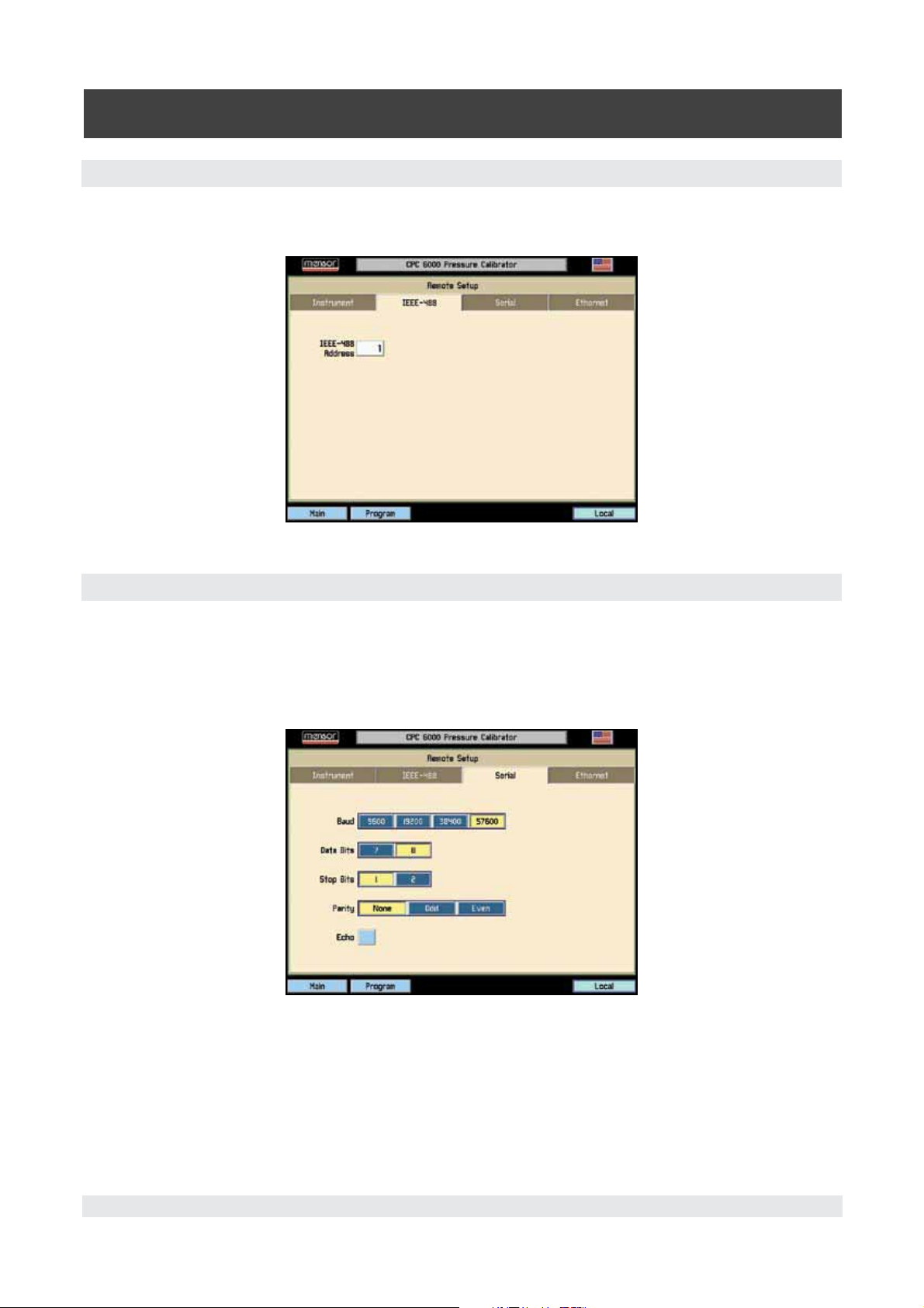
7.1.2 [IEEE-488] Setup Screen
Press the [IEEE-488] tab to set up the IEEE address. Press the white box and a number keypad will
appear for you to enter your new IEEE address and then press [OK].
Figure 7.1.2 - [IEEE-488] Setup Screen
7.1.3 [Serial] Setup Screen
Press the [Serial] tab to set up the serial port parameters. These parameters should be set up to match
your host computer. Default settings are: 57600, 8,1, none parity, and no echo.
If the Echo check box is checked, the CPC 6000 will immediately echo back characters sent over the
serial port.
Figure 7.1.3 - [Serial] Setup Screen
46 Mensor/WIKA Operating Instructions - CPC 6000
Page 47
Automated Pressure Calibrator
CPC 6000
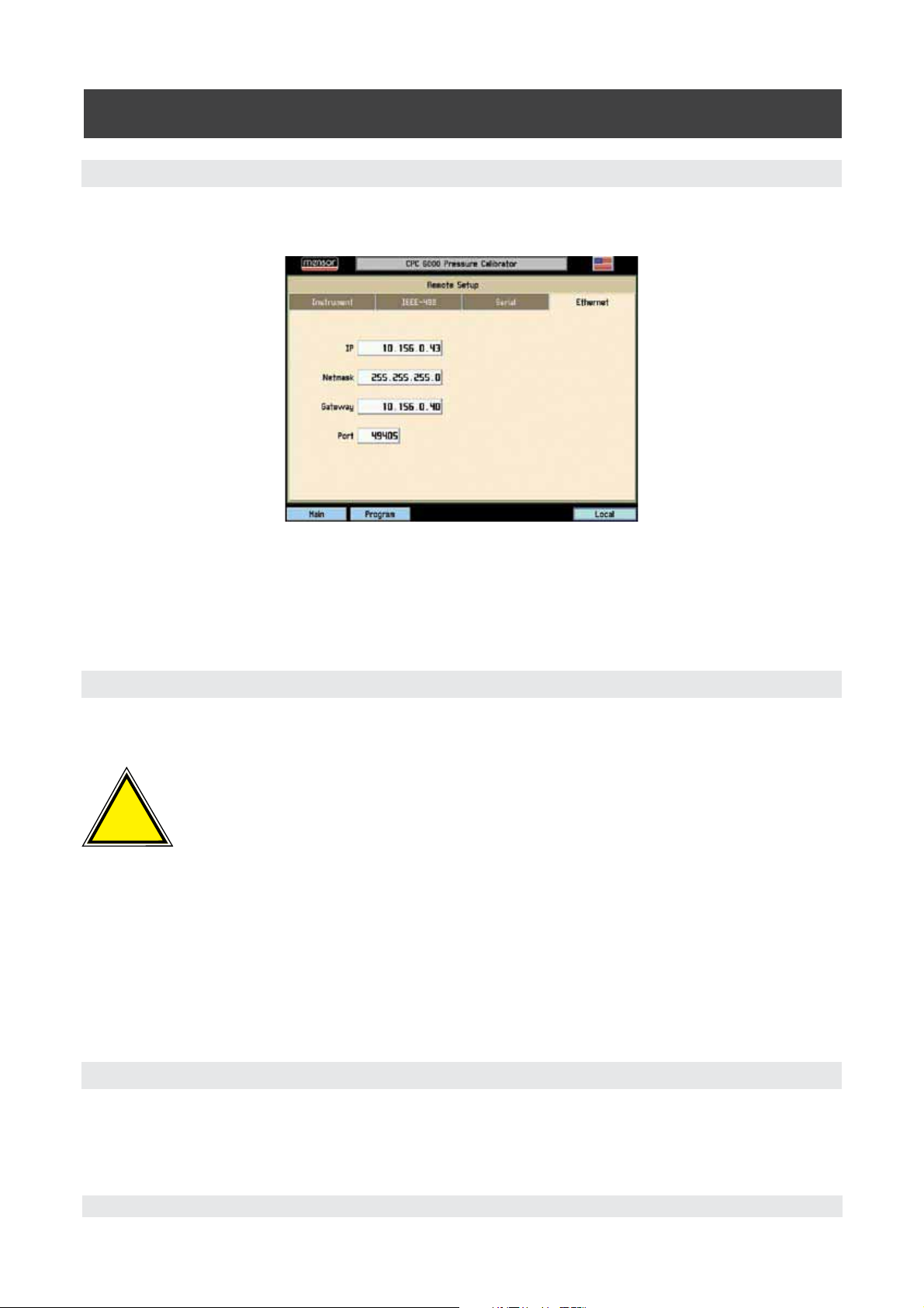
7.1.4 [Ethernet] Setup Screen
Press the [Ethernet] tab to set up the Ethernet parameters. These parameters should be set up to
match your host computer.
Figure 7.1.4 - [Ethernet] Setup Screen
When the correct values have been selected for all four parameters simply touch any of the keys
across the top or the bottom of the screen or the [X] key on the upper right of the window to move on
to another function. Emulation modes are also available for legacy instrument replacement. Contact
Mensor for availability.
.
7.2 Ethernet Communication
The ethernet communication port allows the CPC 6000 to communicate with computers using
10/100Based-T specifications.
CAUTION: Please consult your Computer Resources Department prior to connect-
!
Caution
Ethernet communications are transmitted over a standard RJ-45 cable.
Connecting directly to a PC requires a crossover ethernet cable. Hub connection requires a straight
ethernet cable.
Prior to first time use of ethernet communication, the four parameters, IP, Netmask, Gateway, and Port
must be setup. These are set up in the Remote setup screen.
ing this instrument to your network to verify there are no conflicts with existing IP
addresses.
7.3 IEEE-488 (GPIB)
The manufacturer of the host IEEE-488 interface board provides software to allow communication be
tween the board and various programming languages. An interactive program for debugging is usually
provided as well. Refer to the board manufacturer’s documentation for more information.
Mensor/WIKA Operating Instructions - CPC 6000 47
-
Page 48

Automated Pressure Calibrator
CPC 6000
7.3.1 Capability Codes
SH1 Full source handshake capability
AH1 Full acceptor handshake capability
T6 Talker with serial poll and unaddress if MLA
L4 Listener with unaddress if MTA
SR1 Full service request capability
RL1 Full remote/local capability including LLO
PP0 No parallel poll capability
DC1 Full device clear capability
DT1 Full device trigger capability
C0 No controller capability
E2 Tri-state outputs
7.3.2 Interface Functions
The CPC 6000 responds to the following IEEE-488 interface functions:
SRQ Service Request: A service request is asserted whenever an error is encountered. When
the bus controller issues a serial poll the error will be cleared. If the host IEEE board in
cludes automatic serial polling capability, turn this feature off in order to view all errors (see
ERROR? command).
LLO Local Lockout: The front panel keyboard of the CPC 6000 may be locked by sending LLO
or the command LOCK ON.
GET Group Execute Trigger: When this message is received, the CPC 6000 will save the current
readings until the next time it is addressed as a talker.
GTL Go To Local: A GTL message will cause the CPC 6000 return to local operation and unlock
the keyboard.
DCL Device Clear: When this message is received, the CPC 6000 will clear all errors and buffers
and remain in the REMOTE mode.
SDC Selected Device Clear: The effect is the same as DCL.
EOI End or Identify: May be used as a command or query terminator in the place of, or concur-
rent with, a terminating linefeed.
7.4 RS-232 Serial Communication
The serial communication port allows the CPC 6000 to communicate in RS-232 format with comput
ers, terminals, PDAs, or similar hosts.
-
7.4.1 Cable Requirements
RS-232 communications are transmitted over a three conductor, shielded cable terminated in a stan
dard DB9S connector on the instrument end, and usually the same connector on the host end. Figure
7.4.1 illustrates the proper pin-outs. Notice that each pin 2 is connected to pin 3 on the opposite end.
This configuration is commonly referred to as a 9-pin null modem cable.
48 Mensor/WIKA Operating Instructions - CPC 6000
-
Page 49

Automated Pressure Calibrator
CPC 6000
Figure 7.4.1 - Serial Cable
7.4.2 Command and Query Format
Commands must be sent in ASCII format and terminated with either a carriage return (<cr>), linefeed
(<lf>) or both. Commands are not case sensitive. Each query returns a response. If an error is detected
the response will include an error flag.
One of the first commands issued when starting remote communications should be “Keylock Yes”.
This will disable the on-screen keys and tabs, and place the “Keylock” label on the screen. Turning
keylock on prevents the potential conflicts that could occur if someone pressed an on-screen key,
either intentionally or by accident.
Command/Query Field: Unless otherwise specified, commands are typically converted to queries by
appending a question mark to the command. Table 7.4.5 lists all of the CPC 6000 command/query
keywords.
Data Field: The data field is either in ASCII {string} or numeric {value} form. In the case of multiple
data fields, commas are required to separate the fields. Queries do not have a data field. String (text)
or value (numeric) data are acceptable in any of the following formats:
Examples of {string} data: ON OFF mBar inHg
Examples of {value} data: 1 1.0 -5.678 25.68324e-5
7.4.3 Command Set Definitions
In this manual a data entry made up of alpha characters is defined as a string, as opposed to data
containing only numbers, such as “Enter 1 for ON or 0 for OFF” where 1 and 0 are defined as values.
Command: Any command or query listed in Table 7.4.5.
Separator: Space (SP).
Data: ASCII representations of numbers, {value}, or alpha characters, {string}, data as defined above.
When sending code a literal variable replaces the braces and the enclosed character(s) shown in the
following examples.
Termination: Linefeed (LF) or carriage return (CR) is used to signal the end of a command statement.
For IEEE-488 operation “EOI” is an acceptable alternative.
Mensor/WIKA Operating Instructions - CPC 6000 49
Page 50

Automated Pressure Calibrator
CPC 6000
Always send commands in one of the following formats:
1. [Command] [Termination];
2. [Command] [Separator] [Data] [Termination];
3. Queries are special instructions in the form:
[Command?] [Termination] where the question
mark, “?”, immediately precedes the terminator.
When a valid query is received, the CPC 6000 will return {data} terminated by CR and LF.
Floating point data is returned in the current engineering units in exponential format.
7.4.4 Output Formats
Pressure readings are returned in exponential notation in a format according to the OUTFORM com
mand as follows:
1. <sp> pressure value <cr><lf>
2. <sp> pressure, units number, mode <cr><lf>
3. <sp> pressure, pressure rate <cr><lf>
4. <sp> pressure, minimum peak, maximum peak<cr><lf>
5. <sp> pressure, active sensor (P or S), active turndown (1-4)<cr><lf>
6. <sp> pressure, control point, “stable” or “slewing”<cr><lf>
7. <sp> pressure, “no barometer” or baro reading <cr><lf>
The space <sp> at the beginning of the string is replaced with an “E” if the CPC 6000 has detected a
remote communication error.
For commands that take boolean data the following strings are acceptable:
0 1
False True
No Yes
Off On
-
50 Mensor/WIKA Operating Instructions - CPC 6000
Page 51

Automated Pressure Calibrator
7.4.5 Commands and Queries
Table 7.4.5 lists all of the current CPC 6000 specific commands and queries.
Channel specific commands are sent to only the active channel.
i
Notice
See ‘CHAN’ command.
CPC 6000
Optional emulation modes are available in which the CPC 6000 can emulate remote functions of differ
ent brands of pressure controllers. Please contact Mensor for more details.
Table 7.4.5 - CPC 6000 Commands and Queries
Ref Command Data Function / Response
1 ? See “Output Format” text Returns data per the current output format.
2 Acquire? {15 char string}
Returns: <sp>(YES or
NO),{string}<cr><lf>
3 Address {1 to 30} Sets the GPIB Address.
4 Address? <sp>{value}<cr><lf> Returns the GPIB Address within 1 to 30.
5 A? <sp>{value}<cr><lf> Returns the A channel pressure reading.
6 AR? <sp>{value}<cr><lf> Returns the A channel rate.
7 ARS? <sp>{YES or NO}<cr><lf> Returns the A channel rate stable flag.
8 AS? <sp>{YES or NO}<cr><lf> Returns the A channel stable flag.
9 Autorange {ON or OFF} Toggles autorange function to its opposite state,
10 Autorange? <sp>{ON or OFF}<cr><lf> Returns whether the autorange function is en-
11 Autozero none Re-zero all ranges that can measure the vented
12
Autozero? S,T,X,X Returns autozero data where S represents
Autozero-
13
abort
14
Baro? <sp>{value}<cr><lf> Returns reading from barometric sensor.
15
B? <sp>{value}<cr><lf> Returns the B channel pressure reading.
none Aborts autozero.
This command is used when multiple comput
ers would like to control the instrument. Yes if
acquisition is successful, No if instrument is be
ing controlled with another computer. The string
is an identifier for the controlling computer. See:
Release? And Unlock.
either ON or OFF (enabled or disabled).
abled or disabled.
pressure. These adjustments are not password
protected and are not saved through power
cycles. This command takes approximately 60
seconds.
state (responses can be 0 = complete, 1 = local
autozero, or 2 = remote autozero), T represents
the estimated remaining time to complete in
seconds, and X is a (0) character since this data
location is not used at this time.
-
-
-
Mensor/WIKA Operating Instructions - CPC 6000 51
Page 52

Automated Pressure Calibrator
CPC 6000
16 BR? <sp>{value}<cr><lf> Returns the B channel rate.
17
BRS? <sp>{YES or NO}<cr><lf> Returns the B channel rate stable flag.
18 BS? <sp>{YES or NO}<cr><lf> Returns the B channel stable flag.
19 Caldisable {YES or NO} Disables the zero and span commands (default
= YES). When the cal-disable is YES, the zero
and span commands are disabled.
20 Caldisable? <sp>{YES or NO}<cr><lf> Returns whether or not calibration of the active
sensor is disabled.
21
Cerr none Clears the error queue.
22 Chan {A or B} Sets the active channel on the instrument.
23 Chan? <sp>{A or B}<cr><lf> Returns which channel is active.
24 Chanfunc <sp>{Press,peak,rate,baro}<
cr> <lf>
25 Chanfunc? <sp>{string}<cr><lf> Returns the alternate function mode of the
26
Control none Instrument placed in Control mode.
27 Control? <sp>{YES or NO}<cr><lf> Returns YES if active channel is in Control
28
Crate {Slow, Medium, Fast, Vari-
able} for mid or high range
regulator, {Slow or Fast} for
low range regulator.
Crate? <sp>{string}<cr><lf> Returns the current rate - value corresponds to
29
30
Decpt <sp>{4, 5 or 6}<cr><lf> Sets the number of significant digits displayed.
31
Decpt? <sp>{value}<cr><lf> Returns the number of significant digits dis-
32 Default none Sets the default values. This command takes
33 DIO {0 or 2} 0 turns the digital IO output pin off or low.
34 DIO? {value} 0 if input is low and output is low.
35 DOC <mm/dd/yyyy> Sets the date of cal for the active sensor and
36
DOC? <sp>{mm/dd/yy}<cr><lf> Returns the date of cal for the active sensor and
37 DOM? <sp>{mm/dd/yyyy}<cr><lf> Returns the date of manufacture.
38
Error? <sp>{string}<cr><lf> Returns a description of an error.
Sets the alternate function mode of the active
channel.
channel.
mode; NO if otherwise.
Sets the control slew rate for the current chan
nel. For Variable rate see: Rsetpt command.
the parameters for the CRATE command.
played for the active channel.
approximately 20 seconds.
2 turns the digital IO output pin on or high.
1 if input is high and output is low.
2 if input is low and output is high.
3 if input is high and output is high.
turndown.
turndown.
-
52 Mensor/WIKA Operating Instructions - CPC 6000
Page 53

Automated Pressure Calibrator
CPC 6000
39 Errorno? <sp>{string}<cr><lf> Returns CPC 6000 error code and text.
40
Filter {Off, Low, Normal, High} Sets the reading filter.
41
Filter? <sp>{string}<cr><lf> Returns the reading filter.
42 Gasdensity {value} Sets the head pressure gas density in lb/ft^3.
43 Gasdensity? <sp>{value}<cr><lf> Returns the head pressure gas density in lb/ft^3.
44 Gastemp {value} Sets the head pressure gas temperature in °F.
45 Gastemp? <sp>{value}<cr><lf> Returns the head pressure gas temperature.
46
Gateway {string e.g. nnn.nnn.nnn.nnn} Sets the Ethernet gateway address.
47 Gateway? <sp>{string}<cr><lf> Returns the Ethernet gateway address.
48
Height {value} Sets the head pressure height in inches.
49
Height? <sp>{value}<cr><lf> Returns the head pressure height.
50
Highspeed {Yes or No} Sets the active channel to high speed mode:
.006% stablewindow and 1 second stabledelay.
51
ID? <sp>MENSOR,600,{ssssss},{
v.vv}<cr><lf>
52 IP {string e.g. nnn.nnn.nnn.nnn} Sets the IP address of the instrument.
53 IP? <sp>{string}<cr><lf> Returns the IP address of the instrument.
54 Keylock {Yes or No} YES to lock, or NO to unlock the on-screen
55 Keylock? <sp>{Yes or No}<cr><lf> Returns current keylock status as YES or NO.
56
List? <sp>Pri,X,X;Sec,X,X;Bar,1<c
r><lf>
57 Listcal? <sp>PRI,{sn},{td},{mm/
dd/yyyy},{td},{mm/dd/
yyyy};SEC,{td},{mm/dd/
yyyy},{td},{mm/dd/yyyy}<cr>
<lf>
Listrange? <sp>PRI,{td},{min},{max},{td},
58
{min},{max};SEC,{td},{min},{m
ax},{td},{min},{max}<cr><lf>
Returns the instrument identity where {ssssss}
is the serial number, and {v.vv} is the software
version number.
keys.
Returns list of available turndowns on installed
sensors in the active channel. X will be non-existent if the turndown is not available.
Returns the serial number of each installed
transducer and calibration dates for each range.
Returns the minimum and maximum ranges of
all installed sensors for the active channel.
Mensor/WIKA Operating Instructions - CPC 6000 53
Page 54

Automated Pressure Calibrator
CPC 6000
59 Locale {locale code} Sets Language
and Country code.
Locale Code
en_us
en_ca
en_gb
fr_fr
fr_ca
es_es
es_mx
de_de
it_it
zh_cn
ko_ko
ru_ru
de_ch
fr_ch
en_ie
ja_jp
pl_pl
Language
english
english
english
french
french
spanish
spanish
german
italian
chinese
korean
russian
german
french
english
japanese
polish
Country
usa
canada
great brittain
france
canada
spain
mexico
germany
italy
china
korea
russia
switzerland
switzerland
ireland
japan
poland
60 Locale? <sp>{string}<cr><lf> Returns current language and Country locale.
61 Localgravity {value} Sets the acceleration of gravity in feet/sec^2.
62
Localgravity? <sp>{value}<cr><lf> Returns the local gravity in feet/sec^2.
63
LowerLimit Value inside primary trans-
ducer range on turndown #1
Sets the lower control limit for the active channel.
in current units.
64
LowerLimit? <sp>{value}<cr><lf> Returns the lower control limit for the active
channel.
65
Lowover-
{Yes or No} Sets the active channel to low overshoot mode.
shoot
66 Lowover-
shoot?
67
Measure none Instrument placed in Measure mode.
<sp>{Yes or No}<cr><lf> Returns the current setting of the lowovershoot
mode.
68 Measure? <sp>{Yes or No}<cr><lf> Returns YES if active channel is in Measure
mode; NO if otherwise.
69 Mode {standby, measure,control,
Sets the operation mode of the active channel.
vent}
70
Mode? <sp>{string}<cr><lf> Returns the operation mode of the active chan-
nel.
71
Netmask {nnn.nnn.nnn.nnn} Sets the Ethernet network mask.
72 Netmask? <sp>{nnn.nnn.nnn.
Returns the Ethernet network mask.
nnn}<cr><lf>
73 Outform {1 to 8}
Sets the output format. See ‘Output Formats’ in
Section 4, Remote Operation.
74 Outform? <sp>{X}<cr><lf> Returns the current output format.
54 Mensor/WIKA Operating Instructions - CPC 6000
Page 55

Automated Pressure Calibrator
CPC 6000
75 Peakmax? <sp>{value}<cr><lf> Returns the maximum pressure since peakreset
was sent.
76
Peakmin? <sp>{value}<cr><lf> Returns the minimum pressure since peakreset
was sent.
77 Peakreset none Resets the peak values.
78
Port {value} Sets the Ethernet port of the instrument.
79
Port? <sp>{value}<cr><lf> Returns the Ethernet port of the instrument.
80 Precision none Sets the active channel to the precision mode:
.003% stablewindow and 4 second stabledelay.
81 Ptype {Absolute or Gauge or A or G} Sets the instrument pressure type – non-native
type only works if the optional barometric sen
sor is installed.
82
Ptype? <sp>{Absolute
orGauge}<cr><lf>
83
RangeMax? <sp>{value}<cr><lf> Returns the maximum range of the active trans-
Returns “Absolute” or “Gauge” for the pressure
type.
ducer and turndown in the current units.
84
RangeMin? <sp>{value}<cr><lf> Returns the minimum range of the active trans-
ducer and turndown in the current units.
85
Rate? <sp>{value}<cr><lf> Returns the rate reading of the instrument in
current units/second.
86 Rdecpt? <sp>{value}<cr><lf> Returns the number of rate decimal points for
the active channel. See: Resolution
87
Reference {EXTVAC or ATM} Sets the reference type for vacuum pump
connected to the reference, or vented to atmo
sphere. This option is only available on native
gauge units.
88 Reference? <sp>{EXTVAC or
ATM}<cr><lf>
Returns the current reference type of the active
channel. See: Reference
89 Release? {15 char string} Returns: <sp>(YES or NO), {string}<cr><lf>
This command is used to release control of the
instrument when it is accessed by more than
one computer. To release control of the instru
ment, {string} must be identifier used for the
“Acquire” command. Yes if release is successful.
No if instrument is being controlled with another
computer. Return {string} = identifier of the con
trolling computer or AVAILABLE. See: Acquire?
and Unlock.
90 Repeat None Repeats output continually over serial port only.
91 Resolution {4 to 6} Sets the number of significant digits. See: decpt
92
Resolution? <sp>{value}<cr><lf> Returns the number of significant digits.
93
Rsetpt {value} Sets the rate setpoint of the active channel in
current units per second. Must be a value inside
the current sensor range.
-
-
-
-
Mensor/WIKA Operating Instructions - CPC 6000 55
Page 56

Automated Pressure Calibrator
CPC 6000
94 Rsetpt? <sp>{value}<cr><lf> Returns the current rate setpoint of the active
channel in current units per second.
95
Sbaud {9600, 19200, 38400, 57600} Sets the serial baud rate.
96 Sbaud? <sp>{value}<cr><lf> Returns the serial baud rate.
97
Sdata {7 or 8} Sets the serial data bits.
98 Sdata? <sp>{value}<cr><lf> Returns the serial data bits number.
99 Sensor C, X Sets the active sensor where C = Primary or
Secondary and X is the turndown.
100 Sensor? <sp>{C,X}<cr><lf> Returns the active sensor as above.
101 Sensor.acc? <sp>{value}<cr><lf> Returns the accuracy of the sensor.
102
Sensorid? <sp>{Address}<sp>MENSOR
,<sp>600SNSR,<sp>{Serial
No.},V{V.VV}<cr><lf>
103
Setpt {A value inside the upper/low-
er limits, and inside the range
of the active transducer and
turndown}
Setpt? <sp>{value}<cr><lf> Returns the control setpoint of the active chan-
104
105
Span {desired pressure or ?} Sets span on active transducer (must be >50%
106 Span? <sp>{value}<cr><lf> Returns span scale factor for active transducer
107
Sparity {Even, ODD , NONE} Sets the serial parity.
108 Sparity? {<sp>{string}<cr><lf> Returns the serial parity.
109 Srqmask Stable, Error or both Sets the CPC 6000 to issue a service request
110 Srqmask? <sp>{string}<cr><lf> Returns “stable”, “error” or “error, stable” de-
111 Sstop {1 or 2} Sets the serial stop bits.
112
Sstop? <sp>{value}<cr><lf> Returns the serial stop bits.
113
Stable? <sp>{Yes or No}<cr><lf> Returns YES if instrument is stable or NO.
114
Stabledelay {0 to 65535} Sets the stable time to the number of seconds
115
Stabledelay? <sp>{value}<cr><lf> Returns the stable time.
116 Stabletime {0 to 65535} Sets the stable time to the number of seconds
117
Stabletime? <sp>{value}<cr><lf> Returns the stable time.
Returns the active sensor’s serial number and
firmware version.
Sets the control setpoint for the active channel.
nel in current units.
FS, and within 1% limit), or ? to clear previous
value. (See “Caldisable” command above ref#
19)
and turndown.
(SRQ) over the IEEE-488 when the pressure
control is stable, or an error occurs. These are
80 hex and 40 hex respectively.
pending on the SRQ.
specified.
specified.
56 Mensor/WIKA Operating Instructions - CPC 6000
Page 57

Automated Pressure Calibrator
CPC 6000
118 StableWin {%fs value} Sets the stable window as a %FS.
119 StableWin? <sp>{value}<cr><lf> Returns the stable window in % of Span.
120
Standby none Instrument placed in Standby mode, all sole-
noids de-energized.
121
Standby? <sp>{Yes or No}<cr><lf> Returns YES if the active channel is in Standby,
NO if otherwise.
122
Step <sp>{value inside upper and
lower limits and inside the
range of the active sensor
and turndown}<cr><lf>
Step- {none or value} Jogs the setpoint down one step. If a value is
123
124
Step+ {none or value} Jogs the setpoint up one step. If a value is en-
125
Step? <sp>{value}<cr><lf> Returns the control step for the instrument.
126
Stop none Stop repeating output over serial port. See:
127
Units {units code, or output format
text from Measurement Units
Table 11.1 in the Appendix
Section}
Units? <sp>{string}<cr><lf> Returns the instrument units in a text string.
128
129
Unlock none Releases Acquire locks. See: Acquire? and
130
UpperLimit {Value inside primary trans-
ducer range}
131
UpperLimit? <sp>{value}<cr><lf> Returns the upper control limit for the active
132
Vent none Instrument placed in Vent mode.
133
Vent? <sp>{Yes or No}<cr><lf> Returns YES if active channel is in Vent mode,
134
Versions? <sp>{string}<cr><lf> Returns the versions of the firmware for the
135 Volume {value in cc} Sets the system volume in cc’s – only applicable
136
Volume? <sp>{value}<cr><lf> Returns the current system volume in cc’s – only
137
Zero {desired pressure or ?} Sets active sensor and turndown’s zero to en-
138 Zero? <sp>{value}<cr><lf> Returns zero offset value for active sensor and
Sets the control step size for the instrument.
entered, sets the step size to that value.
tered, sets the step size to that value.
Repeat
Sets the instrument engineering units.
Release?
Sets the upper control limit for the active chan-
nel.
channel.
No if otherwise.
instrument, gpib driver, gate array, installer, and
the graphics library.
if the active channel is a low pressure regulator.
applicable if the active channel is a low pressure
regulator.
tered pressure, or ? to clear previous value. (See
“Caldisable” command above ref# 19)
turndown.
Mensor/WIKA Operating Instructions - CPC 6000 57
Page 58

Automated Pressure Calibrator
CPC 6000
7.4.6 CPC 6000 Error Codes
Table 7.4.6 - CPC 6000 Error Codes
Serial
Poll
Code
E00 00h reserved unused code
E01 41h GPIB listen/talk error GPIB LISTEN/TALK ERROR
E02 42h Syntax error UNKNOWN COMMAND
E03 43h Expected a valid _PCS4 command EXPECTED A VALID _PCS4 COMMAND
E04 44h Expected a valid FUNC command EXPECTED A VALID FUNC COMMAND
E05 45h Expected a valid CAL command EXPECTED A VALID CAL COMMAND
E06 46h Expected a valid TEST command EXPECTED A VALID TEST COMMAND
E07 47h Expected a pressure units selection EXPECTED A PRESSURE UNITS SELEC
E08 48h Expected a pressure value EXPECTED A PRESSURE VALUE
E09 49h Expected a transducer selection EXPECTED A XDUCER SELECTION
E10 4ah Expected a seconds selection EXPECTED A SECONDS SELECTION
E11 4bh reserved unused code
E12 4ch
E13 4dh Invalid pressure units selection INVALID PRESSURE UNITS SELECTION
E14 4eh Invalid control pressure value selection INVALID CONTROL PRESSURE VALUE
E15 4fh Invalid rate value selection INVALID RATE VALUE SELECTION
E16 50h Invalid a/d unit selection INVALID A/D UNIT SELECTION
E17 51h Invalid zero offset value selection INVALID ZERO OFFSET VALUE SELECTION
E18 52h Invalid Span offset value selection INVALID SPAN OFFSET VALUE SELECTION
E19 53h Invalid rate units selection INVALID RATE UNITS SELECTION
E20 54h Sensor overrange SENSOR OVERRANGE
E21 55h Sensor underrange SENSOR UNDERRANGE
E22 56h Sensor failure detected SENSOR FAILURE DETECTED
E23 57h Low source pressure LOW SOURCE PRESSURE
E24 58h Regulator failure detected REGULATOR FAILURE DETECTED
E25 59h
E26 5ah Internal leak detected INTERNAL LEAK DETECTED
E27 5bh Program error detected PROGRAM ERROR DETECTED
E28 5ch Memory error detected MEMORY/COEFFICIENT ERROR DETECT
E29 5dh External Leak detected EXTERNAL LEAK DETECTED
E30 5eh High exhaust pressure VACUUM ERROR DETECTED
E31 5fh Transducer error detected XDUCER ERROR DETECTED
Byte Description Error String Returned
-
TION OR INVALID TERMINATION STRING
reserved unused code
SELECTION
reserved unused code
ED
-
58 Mensor/WIKA Operating Instructions - CPC 6000
Page 59

Automated Pressure Calibrator
CPC 6000
E32 60h Invalid transducer selection INVALID TRANSDUCER SELECTION
E33
E34 62h Invalid filter setting selection INVALID FILTER SETTING SELECTION
E35 63h Invalid output format selection NOT A VALID OUTPUT FORM SELECTION
E36 64h Invalid stable window selection INVALID STABLE WINDOW SELECTION
E37 65h Invalid stable delay selection INVALID STABLE DELAY SELECTION
E38
E39 67h Expected a filter setting selection EXPECTED A FILTER SETTING SELECTION
E40
E41
E42
E43
E44
E45
E46
E47
E48 70h Illegal GPIB controller function ILLEGAL GPIB CONTROLLER FUNCTION
E49 71h GPIB error GPIB ERROR
E50 72h Invalid termination INVALID TERMINATION
E51 73h Vent mode disabled VENT MODE DISABLED
E52 74h Special functions not available SPECIAL FUNCTIONS NOT AVAILABLE
E53 75h
E54 76h Expected a valid DPC-179 command EXPECTED A VALID DPC-179 COMMAND
E55 77h Expected a valid DPC-179 header
E56 78h Expected a valid DPC-179 control
E57 79h
E58 7ah
E59 7bh
E60 7ch reserved unused code
E61 7dh reserved unused code
E62 7eh
E63 7fh Cal functions disabled CAL FUNCTIONS DISABLED
61h Invalid filter window selection INVALID FILTER WINDOW SELECTION
66h reserved unused code
68h Expected an output format selection EXPECTED AN OUTPUT FORM SELECTION
69h Expected a stable delay selection EXPECTED A STABLE DELAY SELECTION
6ah Expected a language selection EXPECTED A LANGUAGE SELECTION
6bh reserved unused code
6ch reserved unused code
6dh PCS200 command format error PCS200 COMMAND FORMAT ERROR
6eh Control pressure overrange CONTROL PRESSURE OVERRANGE
6fh Control pressure underrange CONTROL PRESSURE UNDERRANGE
reserved unused code
EXPECTED A VALID DPC-179 HEADER
command
COMMAND
EXPECTED A VALID DPC-179 CONTROL
command
COMMAND
reserved unused code
reserved unused code
reserved unused code
reserved unused code
Mensor/WIKA Operating Instructions - CPC 6000 59
Page 60

Automated Pressure Calibrator
CPC 6000
7.4.7 Remote Emulation
The Mensor PCS 400 is an earlier generation instrument similar to the CPC 6000. There is some
compatibility between the CPC 6000 and a PCS 400 in that the CPC 6000 will respond to many of the
remote instructions as if it were the older instrument. The PCS 400 commands will operate only on the
currently active control channel.
Table 7.4.7.1 is a list of the remote commands and queries which the CPC 6000 will recognize and
respond to.
A space between elements in a command indicates a required delimiter. Use a space where such a
delimiter is indicated. A full description of the syntax and use for each of these commands and queries
are presented in the PCS 400 manual.
All pressure values will be in the currently active pressure units
i
Notice
7.4.7.1 PCS 400 Emulated Commands and Queries
unless otherwise stated.
Table 7.4.7.1 - PCS 400 Emulated Commands and Queries
Ref Command Data Function / Response
1 _pcs4 autorange <value> 0 or 1 1 turns autorange on, 0 turns autorange off.
2 _pcs4 autorange? Returns 1 if in autorange, 0 if in range hold.
3 _pcs4 cal span <value> Sets the span of the active transducer to <value>.
4 _pcs4 cal zero <value> Sets the zero of the active transducer to <value>.
5 _pcs4 cal_disable_off Enables zero or span calibrations if previously disabled.
6 _pcs4 cal_disable_on Prevents zero or span calibrations.
7 _pcs4 ctrl <value> Sets control value. Will take effect immediately if instru-
ment is in control mode.
8 _pcs4 ctrl? Returns the current control point in current engineering
units.
9 _pcs4 ctrlmax <value> Sets maximum control value.
10 _pcs4 ctrlmax? Returns current maximum control pressure.
11 _pcs4 ctrlmin <value> Sets minimum control value.
12 _pcs4 ctrlmin? Returns current minimum control pressure.
13 _pcs4 default Sets default values into instrument.
14 _pcs4 err? Returns the error number and description.
15 _pcs4 func ctrl <value>
<unitno>
16 _pcs4 func F1 Toggles between absolute and gauge modes if an inter-
17 _pcs4 func meas Instrument placed in measure mode.
Instrument placed in control mode at <value> pressure
in <unitno> units.
nal barometric sensor is installed.
60 Mensor/WIKA Operating Instructions - CPC 6000
Page 61

Automated Pressure Calibrator
CPC 6000
18 _pcs4 func stby <unitno> Instrument placed in standby mode in <unitno> units.
19 _pcs4 func vent <unitno> Instrument placed in vent mode in <unitno> units.
20 _pcs4 id? Returns instrument ID.
21 _pcs4 opt? Returns instrument options.
22 _pcs4 outform <digit> Sets output format.
23 _pcs4 outform? Returns the current output format.
24 _pcs4 rangemin? Returns the minimum pressure of the active transducer.
25 _pcs4 span? Returns the stored multiplication factor from the active
transducer and turndown.
26 _pcs4 stabledelay <value> 1 to
255
27 _pcs4 stabledelay? Returns the number of readings that must be within the
28 _pcs4 stablewindow
<value>
29 _pcs4 stablewindow? Returns the pressure tolerance allowed for a stable pres
30 _pcs4 stat? Returns mode and stable flag status “mode, stable CR
31 _pcs4 unit <unitno> Sets the instrument to specified engineering units.
32 _pcs4 unit? Returns the current engineering units and type of trans-
33 _pcs4 xducer? Returns the number of the currently active transducer.
34 _pcs4 zero? Returns the stored zero offset of the active transducer
Sets the number of consecutive readings that the pres
sure must remain within the stable window for a pres
-
sure stable indication.
stable window before a stable pressure is indicated.
Sets the pressure window that is used to indicate pres
sure is stable.
sure indication asa%ofspan of the active transducer.
LF”.
ducer (A, G, D).
and turndown in the current pressure units.
-
-
-
7.4.7.2 PCS 200 Emulated Commands and Queries
Table 7.4.7.2 – PCS 200 Emulated Commands and Queries
Command Data Function / Response
CX Control Pressure at last control point and units
C$nnnnnnnX Control Pressure at n in units $
D#X CAL POINT CONTROL MODE NOT SUPPORTED
EX Clear Error/Clear Service Request
E?X Return error code and clear error
F$nnnnnnn1X Re-initialize; $,n ignored
F$nnnnnnn2X RETURN CAL DATA NOT SUPPORTED
F$nnnnnnn3X Return Unit ID string; $,n ignored
F$nnnnnnn5X RETURN QPS TEMPERATURE NOT SUPPORTED
Mensor/WIKA Operating Instructions - CPC 6000 61
Page 62

Automated Pressure Calibrator
CPC 6000
F$nnnnnnn6X RETURN NULL METER READING NOT SUPPORTED
F$nnnnnnn7X RETURN VACUUM GAUGE READING NOT SUPPORTED
F$nnnnnnn8X Return Clock Reading (Time); $,n ignored
F$nnnnnnn9X Return Pressure Control Limits; $,n ignored
MX Measure Pressure in current pressure units
M$X Measure Pressure in units specified by $
M$nnnnnnnX Measure Pressure in units specified by $; n ignored
M$nnnnnnnnsX Measure Pressure in units specified by $; n,s ignored
Q#X SEQ FUNCTIONS NOT SUPPORTED
RX Not supported
R0X Return to Standard Output Format
R1X Re-initialize DO NOT USE - sets CPC 6000 to command prompt.
R2X RETURN CAL DATA NOT SUPPORTED
R3X Return unit ID string
R5X RETURN QPS TEMPERATURE NOT SUPPORTED
R6X RETURN NULL METER READING NOT SUPPORTED
R7X RETURN VACUUM GAUGE READING NOT SUPPORTED
R8X Return Clock Reading (Time)
R9X Return Pressure Control Limits (Min and Max)
SX Standby Mode
S$X Standby Mode; $ ignored
S$nnnnnnnX Standby Mode; $,n ignored
S$nnnnnnnsX Standby Mode; $,n,s ignored
U$X Change Units to units specified by $
VX Vent Mode in current units
V$X Vent Mode in units specified by $
V$nnnnnnnX Vent Mode in units specified by $; n ignored
V$nnnnnnnsX Vent Mode in units specified by $; n,s ignored
ZX Automatic re-zero
62 Mensor/WIKA Operating Instructions - CPC 6000
Page 63

Automated Pressure Calibrator
CPC 6000
7.4.7.3 SCPI Commands
STATus :
OPERation
:CONDition? Returns an integer value representing instrument status
that can be decoded.
Bit 0: Zeroing active.
Bit 1: Control Setpoint has not been reached.
Bit 2: Reserved 0.
Bit 3: Reserved 0.
Bit 4: Measuring. The instrument is actively measuring.
MEASure
[:PRESsure] [z]? Returns the pressure from the active sensor, or active
sensor if [z] is omitted.
:TEMPerature[z]? Returns the temperature in deg. C. from the specified sen
sor, or active sensor if [z] is omitted.
:RATE[z]? Returns the pressure rate from the specified sensor, or ac
tive sensor if [z] is omitted.
:BAROmetric? Returns the barometric pressure, if a barometer sensor is
installed.
-
-
CALibration
:MODE? Returns 1 if the sensor has been calibrated or 0 if not.
:DATE? Returns the stored calibration date.
:DATE <i,i,i> Sets the calibration date (YYYY,MM,DD).
:ZERO? Returns current zero point correction.
:ZERO <n> Sets the zero so the currently measured pressure matches
the commanded value. Limited to +/-5% FS.
ZERO:RUN Vents the instrument and sets zero so the currently mea
-
sured pressure = 0.
SENSE
[:PRESsure] [z] Selects the sensor to read or modify or active sensor if [z]
is omitted.
:NAME? Returns the accuracy and range of the sensor.
:MODE? Returns pressure type “ABSOLUTE” or “GAUGE”
:MODE ABS/GAUGE Sets the pressure type to absolute or gauge.
:ABS? Returns native sensor type “1” for absolute, ”0” for gauge.
:RESolution? Returns the FS-related relative resolution of the sensor.
:RANGE
[:UPPer]? Returns the maximum range of the primary sensor.
:LOWer? Returns the minimum range of the primary sensor.
:Unit
[:NAME]? Returns a string representing the native units of the sen
-
sor.
:VALue? Returns the conversion factor of the native units of the
sensor.
:REFerence
[:HEIGht] <n> Sets the head height correction [mm].
:MODE? Returns head correction mode - “OFF”, “GAS”, LIQUIT”.
Mensor/WIKA Operating Instructions - CPC 6000 63
Page 64

Automated Pressure Calibrator
CPC 6000
:MODE OFF/GAS/LIQUIT Sets the head correction mode.
:MEDIUM <n> Sets the density of the medium.
SYSTem
:DATE <i,i,i> Sets the system date (YY,MM,DD).
:TIME <i,i,i> Sets the system time (hh,mm,ss).
:ERRor[:NEXT]? Return: error#, “description”.
:KLOCk ON/OFF/1/0 Lock or unlock keyboard.
:PRESet Load known values.
:SAVe Saves settings to non-volatile memory.
:VERSion? Return of the SCPI-standard.
TEST
:ELECtronic? Returns electronics status.
:RELay<n>? Returns whether relay 1 to 3 is closed or not.
:RELay<n> ON/OFF Turns relay 1 to 3 on or off.
UNIT
:NAME<n>? Returns the name of the unit with index n.
:FACTOR<n>? Returns the conversion factor of the unit with index n.
index unit
0 bar
1 mbar
2 Pa
3 psi
4 atm
5 kp/cm2
6 lbf/ft2
7 kPa
8 cmH2O(4°C)
9 inH2O(4°C)
10 inH2O(60°F)
11 ftH2O(4°C)
12 μmHg(0°C)
13 mmHg(0°C)
14 cmHg(4°C)
15 inHg(0°C)
16 inHg(60°F)
17 - -
18 user
19 user
20 user
OUTPut
:STATe ON/OFF/1/0 Turns control mode on or off.
:STATe? Returns control mode “0” for off, ”1” for on.
:MODE MEASure/CONTrol/VENT Sets the operation mode.
:MODE? Returns current operation mode MEASURE”,
CONTROL”or “VENT”.
:STABLE? Returns 1 if in control mode and stable.
64 Mensor/WIKA Operating Instructions - CPC 6000
Page 65

Automated Pressure Calibrator
CPC 6000
:AUTOvent ON/OFF/1/0 Sets autovent function on or off (automatically vent when
controlling at zero).
:AUTOvent? Returns status of Autovent function.
[SOURCE]
:PRESsure
[:LEVel]
[:IMMediate]
[:AMPLitude] <n> Sets the control pressure.
[:AMPLitude]? Returns current control pressure value.
:SLEW <n> Sets the slew rate in %FS/s.
:SLEW? Returns the current slew value in %FS/s.
:TOLerance <n> Sets the tolerance for stable indication in %FS.
:TOLerance? Returns the tolerance for stable indication in %FS.
CALCulate
:LIMit
:LOWer <n> Sets minimum control limit.
:LOWer? Returns minimum control limit.
:UPPer <n> Sets maximum control limit.
:UPPer? Returns maximum control limit.
7.4.7.3.1 Output Formats
1. <sp>pressure value<cr><lf>
2. <sp>pressure, units number, mode<cr><lf>
3. <sp>pressure, pressure rate<cr><lf>
4. <sp>pressure, minimum peak, maximum peak<cr><lf>
5. <sp>pressure, active sensor (P or S) active turndown (1-4)<cr><lf>
6. <sp>pressure, control point, “stable” or “slewing”<cr><lf>
7. <sp>pressure, “no barometer” or baro reading<cr><lf>
7.4.7.3.2 Error Messages and Error Codes
A recognized command is displayed at the device in the headline with “Remote...”. In case of error
“Remote error...” is displayed. A maximum of 100 errors are stored and can be retrieved successfully.
Table 7.4.7.3.2 - SCPI Command Error Messages and Error Codes
Code Error String Returned
0 No error
-101 Undefined character
-102 Syntax error
-103 Undefined separator
-104 Parameter data type error
-109 Parameter missing
-110 Undefined header
-113 Undefined command
-114 Parameter out of range
Mensor/WIKA Operating Instructions - CPC 6000 65
Page 66

Automated Pressure Calibrator
CPC 6000
-313 Calibration data not found
-315 Configuration data not found
-350 Errorqueue overflow
-410 Query interrupted
600 Default configuration not found
601 Calibration mode active! Deactivate before setting C0..C3
602 Sensor not available
701 DCS instance not available
702 Create DCS instance failed
703 DCS still active
704 Command currently not allowed
7.4.7.4 DPI 510 Emulation Commands
The CPC 6000 will accept and respond to Druck Model DPI 510 remote commands over a GPIB as
listed below. These commands can be sent individually, or ganged together. Delimiters (separators)
between commands are not required.
Commands supported by the CPC 6000:
case ‘@’: /*Error Status (on/off)*/
usage “@0” sets error checking off
usage “@1” sets error checking on
case ‘C’: /*Control_Mode / Measure_Mode*/
usage “C0” go to measure mode
usage “C1” go to control mode
usage “C2” go to standby mode
case ‘D’:
/*Display_Mode*/
usage “D0” returns active reading in any mode
usage “D1” returns setpoint only if in control mode, otherwise it returns 0.000
case ‘E’:
/*Clear_Error_Mode*/
usage “E “ The PCS 400 will accept all types of termination; CR/LF/EOI. It will
also accept the strings E0, E1 and E2, but will not respond to these.
Note: Send “E?” to clear an error from the buffer (this is an added function, not part of
the Druck command set).
case ‘F’:
/*Function*/
usage “F00” does not apply to PCS 400
usage “F01” puts instrument into vent mode when C0 or controller is off
usage “F02” does not apply to PCS 400
usage “F03” does not apply to PCS 400
case ‘I’: /*IO Service Request*/
usage “I0” dummy function accepts the string and returns what was entered
66 Mensor/WIKA Operating Instructions - CPC 6000
Page 67

case ‘J’:
case ‘N’:
case ‘P’:
case ‘R’:
case ‘S’:
Automated Pressure Calibrator
CPC 6000
usage “I1” dummy function accepts the string and returns what was entered
usage “I2” dummy function accepts the string and returns what was entered
usage “I3” dummy function accepts the string and returns what was entered
usage “I4” dummy function accepts the string and returns what was entered
usage “I5” dummy function accepts the string and returns what was entered
usage “I6” dummy function accepts the string and returns what was entered
/*Rate_Mode*/
usage “J0” sets the rate mode to variable rate mode
usage “J1” sets the rate mode to variable rate mode
usage “J2” sets the rate mode to regular control mode (default) MAX
Note: All of the notation formats have a leading space!
/*Notation_Mode*/
usage “N0” output format default responds with pressure/remote/range/scale/
display/error
usage “N1” output format responds with pressure or setpoint depending on the
display mode setting
usage “N2” output format responds with range/scale/display/control mode/IO/
function/error
usage “N3” output format returns 0 for not stable or 1 for stable
usage “N4” output format returns error/error(on/off)/rate/variable rate/units
N0 if display is set to 1 the pressure reading is the setpoint reading
example 200.00REMR1S3D1@01
if display is set to 0 the pressure reading is the pressure reading
example 199.98REMR1S3D0@01
N1 if display is set to 1 the pressure reading is the setpoint reading
example 200.00
if display is set to 0 the pressure reading is the pressure reading
example 199.98
N2 example R1S3D1C0I0F00@01
N3 example 1
N4 @01@1J0V+00009U BAR
/*Pressure_Setpoint_Mode*/
usage “PXXXX.
XXXX”
usage “R0” no range
usage “R1” range 1 if available (main range)
usage “R2” range 2 if available (secondary range)
usage “S1” sets the scale with one unit selection
usage “S2” sets another scale with another unit selection
usage “S3” sets the global scale enables all units to be selected
X = sets the pressure setpoint (ex. P13.5)
/*Range(xducer)*/
/*Scale*/
Mensor/WIKA Operating Instructions - CPC 6000 67
Page 68

Automated Pressure Calibrator
CPC 6000
case ‘U’: /*Units*/
usage “UX” X = the unit number (ex. U16 = psi)
case ‘V’:
usage “VXXXXX” X = the desired control rate setting (ex. V1)
case ‘W’:
usage “WXXX” X = the desired stable delay setting in seconds (ex. W005 = 5 sec)
Emulated Commands not supported by the CPC 6000:
usage “A” does nothing
usage “E “ does nothing
usage “O” Zeroing, software will accept the command but does not
affect the zero status of the instrument
usage “R0” setting remote to local
usage “R1” setting to remote
usage “I0” does nothing
usage “I1” does nothing
usage “I2” does nothing
usage “I3” does nothing
usage “I4” does nothing
usage “I5” does nothing
usage “I6” does nothing
UNITNO 7 (kg/m2) does nothing
UNITNO 10 (mHg) does nothing
UNITNO 17 (lb/ft2) does nothing
UNITNO 21 (Special) does nothing
/*Variable_Rate_Mode*/
/*Wait_Value_Mode*/
The Measurement Units below use conversion factors as listed in this manual’s Appendix:
Druck Unitno Units Comments
1Pa
2 kPa
3 mPa
4 mbar
5 bar
6 kg/cm2
7 kg/m2 not supported
8 mmHg
9 cmHg
10 mHg not supported
68 Mensor/WIKA Operating Instructions - CPC 6000
Page 69

11 mmH2O
12 cmH2O
13 mH2O 20c
Automated Pressure Calibrator
CPC 6000
14
15
torr
Atm
16 psi
17 1b/ft2 not supported
18 inHg
19 “H2O 04c
20 ‘H2O 04c
21
Special not supported
22 “H2O 20c
23 ‘H2O 20c
Mensor/WIKA Operating Instructions - CPC 6000 69
Page 70

Automated Pressure Calibrator
CPC 6000
NOTES
70 Mensor/WIKA Operating Instructions - CPC 6000
Page 71

Automated Pressure Calibrator
CPC 6000
8. Options
This section lists options available for the CPC 6000. Users might consider letting the factory install
a special feature not listed here. Mensor welcomes the opportunity to quote on such requests. The
cost of adding an enhancement frequently will amortize itself in a very short time because of improved
process efficiency.
8.1 Transport Case (PN 0011159001)
A wheeled transport case is available suitable for moving the CPC 6000 between sites, or as an airfreight (or other) shipping container. The case is constructed of a high impact plastic with a black
exterior. It includes two keys, locks, a piano hinge, an anodized interlocking tongue and groove open
ing, various nickel-chrome and stainless steel fixtures, a vinyl satchel style handle and a retractable
pull-out handle. The interior is filled with high density polyurethane foam with a die-cut cavity to cradle
the instrument with fitting adapters in place, and an additional cavity to store related accessories.
Rugged and weather resistant, the case makes an attractive, practical shipping and moving container.
The case weighs approximately 29 pounds (13.15 kg) unloaded, and can support a load of up to 150
pounds (68.04 kg). Nominal dimensions are 15 inches by 24 inches by 26 inches (38.10 cm x 60.96 cm
x 66.04).
-
Figure 8.1 - Transport Case
8.2 Rack Mount Kit
A rack mount kit allows the customer to in
stall a CPC 6000 into a standard 19” instru
ment rack. It includes pre-installed brackets
on the sides of the instrument as well as
spacer panels and hardware to rack mount
the CPC 6000.
Mensor/WIKA Operating Instructions - CPC 6000 71
-
-
Figure 8.2 - Rack Mount Kit
Page 72

Automated Pressure Calibrator
CPC 6000
8.3 Calibration Sled Kit
The calibration sled allows customers to cali
brate transducers outside the CPC 6000. This
allows the customer to continue using the other
ranges inside the CPC 6000, while calibrating
one of the transducers in order to reduce down
time. The calibration sled kit includes the serial
interface software, the calibration sled, a serial
cable to connect the sled to the host computer,
and a power supply (not pictured) for the cali
bration sled (see Figure 8.3).
8.4 Additional Transducers
A secondary transducer of any standard range, with up to two turndown ranges, can be purchased as
an option. In all other regards, the add-on transducer will meet all of the specifications and operating
parameters outlined throughout this manual.
Each control channel has pressure control limits. Typically, the pump regulator
modules have a maximum limit of 15 psig and the solenoid valve regulator mod-
!
Caution
ules have limits of 50-150 or 1500 psig. If a sensor is placed into a control channel
where the sensor has a higher upper pressure range than the control module, the
maximum control limit will be limited to the maximum range of the control module.
-
-
-
Figure 8.3 - Calibration Sled Kit
While any sensor will function in any control channel, the results may not always be optimum. For
example, if a 1 psi sensor is placed in a control module that has a 1500 psi upper limit, the controlled
pressure stability may not be acceptable. Or if a 1500 psi module is placed in a control module that
has a 30 psi upper limit, it will control very well, but be limited in resolution.
8.4.1 Secondary Transducer Installation
If the add-on transducer is of a higher full scale range than the existing primary transducer, then this
newer transducer becomes the Primary, and the existing transducer must be moved to the Secondary
Transducer berth. For complete installation instructions see the text under “Transducer Replacement”
Section 9, Maintenance.
in
8.5 Barometric Reference Transducer
The Barometric Reference Transducer is a very stable, absolute pressure device used to accurately
measure local atmospheric pressure.
The CPC 6000 will use the barometric pressure measured by the installed barometric reference sensor
in the current channel. If only one barometric sensor is installed, its measurement is shared by both
channels.
72 Mensor/WIKA Operating Instructions - CPC 6000
Page 73

8.5.1 Gauge Pressure Emulation Key
Automated Pressure Calibrator
CPC 6000
On absolute units set the CPC 6000 for gauge pressure measurement and control by touching [Pres
sure Units] which will display the Units pop-up window shown in Figure 6.3.6. In the upper right corner
of this window is an [Absolute/Gauge] toggle key. Press [Absolute] to change to [Gauge], then press
[OK]. The operation screen now shows Units [GE] in place of Units [A]. The “GE” indicates that the
measurement and control values are in Gauge Emulation pressure units.
In the Gauge Emulation mode the atmospheric pressure reading from the barometric reference trans
ducer is subtracted from the absolute pressure reading of the active channel to emulate a gauge pres
sure.
The barometric reference sensor has six significant digits. If a very low pressure gauge sensor is active
and is used in absolute emulation, the combined output may appear quite noisy because of the reso
-
lution of the barometric reference.
Emulation mode uncertainty is the combined uncertainty of the barometric reference transducer and
the active transducer.
8.5.2 Absolute Pressure Emulation Key
On gauge units set the CPC 6000 for absolute pressure measurement and control by touching [Pres
sure Unit] which will display the Units pop-up window. In the upper right corner of this window is an
[Absolute/gauge] toggle key. Press [Gauge] to change to [Absolute], then press [OK]. The operation
screen now shows Units [AE] in place of Units [G]. The “AE” indicates that the measurement and con
-
trol values are in absolute emulation pressure units.
-
In Absolute Emulation mode the atmospheric pressure reading from the Barometric Reference Trans
ducer is added to the gauge pressure reading of the active channel to emulate absolute pressure.
8.5.3 Calibration
The Barometric Reference Transducer can be calibrated in exactly the same manner as the other in
stalled sensors as described in
Section 10, Calibration.
-
8.5.4 Specifications
Accuracy: 0.01% of reading. Uncertainties include all pressure effects, temperature effects over the
calibrated range and calibration stability for six months after re-zeroing.
Pressure Range: Calibrated from 11 to 17 psia.
Resolution: 6 digits.
8.6 Virtual Delta Channel
8.6.1 Delta Functions
Two virtual delta functions are available: A-B and B-A. The delta functions are strictly a mathematical
difference between the two physical channel readings. There is no pressure connection between the
channels.
-
Mensor/WIKA Operating Instructions - CPC 6000 73
Page 74
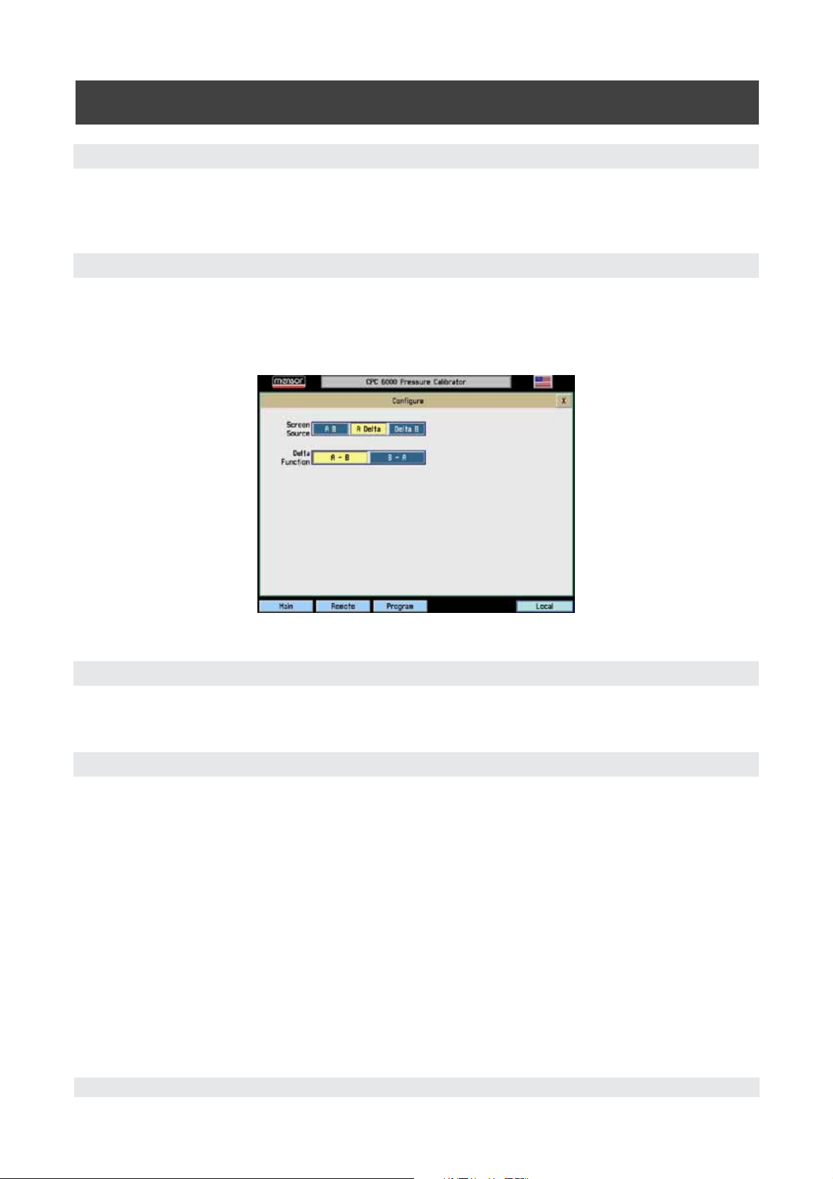
Automated Pressure Calibrator
CPC 6000
8.6.2 Screen Source
The CPC 6000 has two frames in which channel information can be displayed. The frame channel
source can be programmed to A(left) B(right) or A(left) Delta(right) or Delta(left) B(right). Either frame
can be minimized as before.
8.6.3 Configure Button
In order to allow the delta function and frame channel source to be changed, a new button was added
to the lower toolbar. This button is labeled ‘Configure’ and only appears when the Delta function is
enabled. Pressing this button brings up a window with radio buttons to select the desired configura
tion as shown in Figure 8.6.3.
-
Figure 8.6.3 - Configure Button Display Screen
8.6.4 Slave Channel Display
Since the range information is not applicable to the delta channel, the slave channel (the physical one
not displayed) reading is displayed where the range droplist appears in the normal screen.
8.6.5 Screen Source A B
Channels are completely independent. Operates just like a standard CPC 6000.
74 Mensor/WIKA Operating Instructions - CPC 6000
Page 75

Automated Pressure Calibrator
CPC 6000
8.6.6 Screen Source A Delta
A is displayed on the left and is the leading channel. Delta is displayed on the right and is either A-B
or B-A as selected. Channel B’s reading is displayed where the range information normally appears on
the Delta channel. Channel B is the slave channel. Whenever the A channel is changed, the B channel
setpoint is changed to maintain the differential setpoint displayed on the Delta channel. Whenever the
Delta channel setpoint is changed, the B setpoint is changed as well.
Figure 8.6.6 - Screen Source A Delta
8.6.7 Screen Source Delta B
Delta is displayed on the left and is either A-B or B-A as selected. B is displayed on the right and is the
leading channel. Channel A’s reading is displayed where the range information normally appears on
the Delta channel. Channel A is the slave channel. Whenever the B channel is changed, the A channel
setpoint is changed to maintain the differential setpoint displayed on the Delta channel. Whenever the
Delta channel setpoint is changed, the A setpoint is changed as well.
Figure 8.6.7 - Screen Source Delta B
Mensor/WIKA Operating Instructions - CPC 6000 75
Page 76

Automated Pressure Calibrator
CPC 6000
8.6.8 Delta Control Limits
The default control limits for the Delta channel are the maximum limits possible. Certain combinations
of setpoints will generate an illegal setpoint on the slave channel. Note that whether or not the setpoint
is illegal is dependent on the measured reading of the leading channel. In order to prevent the CPC
6000 from rejecting control points that may become legal in the future, all possible setpoints are al
lowed unless restricted by setting the control limits to other values.
8.6.9 Delta Units Type
The delta units type is Differential and a D appears after the units label. Emulation is not available on
the delta channel. If channel A and B are not set to the same pressure type, the delta reading may be
ambiguous.
8.6.10 Setup Screens
The delta channel does not have the following setup buttons: STATUS, CAL, TEST, CONTROL CAL,
control parameters except limits and stable. To change parameters on the slave channel, you must
select the A,B (normal) screen source.
-
8.6.11 New Commands
Table 8.6.11- New Commands
Command Data Function/Response
CHAN D
SCREENSRC A,B
None Sets the active channel to the Differential channel.
None Sets the CPC 6000 to normal operation screen dis-
playing A and B channels.
SCREENSRC
A,Delta
None Sets the CPC 6000 to display A channel as normal,
and Delta channel replaces the B channel location.
In this mode the “A” channel is considered the lead
ing channel.
SCREENSRC
Delta,B
None Sets the CPC 6000 to display B channel as normal,
and Delta channel replaces the A channel location.
In this mode the “B” channel is considered the lead
ing channel.
SCREENSRC? <sp>{A,B or A,Delta
Returns screen source as one of the above options.
or Delta,B}<cr><lf>
*DELTAFUNC A-B
None Sets the delta to be the result of the channel A read-
ing – channel B reading.
*DELTAFUNCB-A None Sets the delta to be the result of the channel B read-
ing – channel A reading.
*DELTAFUNC? <sp>{A-B or B-A}
Returns delta function as one of the above options.
<cr><lf>
-
-
*NOTE: Chan D must be the active channel.
76 Mensor/WIKA Operating Instructions - CPC 6000
Page 77

Automated Pressure Calibrator
CPC 6000
9. Maintenance
The CPC 6000 was designed for maintenance-free operation. User maintenance is not recommended
beyond replacement of parts listed in Table 9.4. If you have questions not covered by this manual, call
1.800.984.4200 (USA only), or 1.512.396.4200 for assistance, or send an e-mail to tech.support@men
sor.com.
9.1 Beyond the Warranty
Take advantage of Mensor’s expert product care. Mensor Corporation provides complete maintenance
and calibration services, available for a nominal fee. Our service staff is knowledgeable in the inner
most details of all of our instruments. We maintain units that are in operation in many different indus
tries and in a variety of applications, and by users with a wide range of requirements. Many of these
instruments have been in service for over twenty years, and continue to produce excellent results.
Returning your instrument to Mensor for service benefits you in several ways:
1. Our extensive knowledge of the instrument assures you that it will receive expert care.
2. In many cases we can economically upgrade an older instrument to the latest improvements.
-
-
-
3. Servicing our own instruments which are used in “real world” applications keeps us informed as to
the most frequent services required. We use this knowledge in our continuing effort to design better
and more robust instruments.
Mensor/WIKA Operating Instructions - CPC 6000 77
Page 78

Automated Pressure Calibrator
CPC 6000
9.2 Troubleshooting the Pneumatic System of the CPC 6000
PROCEED WITH CAUTION! The following test feature is a powerful troubleshooting tool, but it incurs a dangerous potential for misdirecting high pressures. Study
!
Caution
9.2.1 Pump Regulator
The CPC 6000 has two Controller test screens; one is for the Pump Regulator (see Figure 9.2.1A) and
the other is for the Solenoid Valve Regulator (see Figure 9.2.2A).
To get to the test screen press [Setup], [Controller], and [Test]. The pump regulator test screen allows
control of the solenoid valves directly by the operator. Pressing the key labeled [Closed] or [Open] will
toggle the associated solenoid between the open and closed states. As each key is pressed the key
will change text and color, and the target solenoid will
make an audible “click”. If a key changes color
without the accompanying click it is an indication of a
defective solenoid or a bad connection. Pressing the
[+] or [-] key will actuate the pump and increase or
decrease the system pressure respectively. The
[speed] key allows adjustment of the relative rate at
which the pump operates to increase or decrease
pressure. The [%] key allows an adjustment of the
duty cycle of the supply and exhaust valves. The
Primary and Secondary labels show the pressure
sensed at the respective transducers. The Rate [psi/
sec.] label indicated the rate of change of the system
pressure. See Figure 9.2.1B for the pump regulator
pneumatic module. See Figure 9.2.1C for the pneu
matic schematic for the pump regulator.
the pneumatic schematics (Figures 9.2.1C and 9.2.2B) to understand the possible
consequences of various pressure routings.
-
Figure 9.2.1A - Test Screen, Pump Regulator
System pressure should not be
driven above the range of the
!
primary transducer.
The valve isolating the secondary
Caution
transducer should be closed
before the system pressure is
driven above the range of the
secondary transducer.
Figure 9.2.1B - Pneumatic Module, Pump Regulator
78 Mensor/WIKA Operating Instructions - CPC 6000
Page 79

Automated Pressure Calibrator
CPC 6000
Figure 9.2.1C - Pneumatic Schematic, Pump Regulator
Mensor/WIKA Operating Instructions - CPC 6000 79
Page 80

Automated Pressure Calibrator
CPC 6000
9.2.2 Solenoid Valve Regulator
The Solenoid Valve Regulator test screen (figure 9.2.2A) allows control of the solenoid valves directly
by the operator. Pressing [Closed] or [Open] key will toggle the associated solenoid between the open
and closed states. As each key is pressed the key will change text and color, and the target solenoid
will make an audible “click”. If a key changes color without the accompanying click it is an indication
of a defective solenoid or a bad connection. The
[+], [++], and [+++] represent the fine, medium
and course regulator supply valves respectively.
The [-], [--], [---] keys represent the fine, medium
and course regulator exhaust valves respectively.
Applying a continuous touch to any of these keys
will open the respective regulator valve and in
crease or decrease the system pressure. The [%]
key (top left) allows a collective adjustment of the
duty cycle of the regulator valves to adjust the
flow rate through the regulator. The Primary and
Secondary labels show the pressure sensed at the
respective transducers. The Rate [psi/sec.] label
indicated the rate of change of the system pres
sure. See Figure 9.2.2B for the pneumatic sche
matic for the solenoid valve regulator.
-
-
-
Figure 9.2.2A - Test Screen, Solenoid Valve Regulator
!
Caution
System pressure should not be driven above the range of the primary
transducer.
The valve isolating the secondary transducer should be closed before the
system pressure is driven above the range of the secondary transducer.
80 Mensor/WIKA Operating Instructions - CPC 6000
Page 81

Automated Pressure Calibrator
CPC 6000
Figure 9.2.2B - Pneumatic Schematic, Solenoid Valve Regulator
Mensor/WIKA Operating Instructions - CPC 6000 81
Page 82

Automated Pressure Calibrator
CPC 6000
9.2.2.1 Tuning a Solenoid Valve Regulator Module
Figure 9.2.2.1 - Tune Screen, Solenoid Valve Regulator
9.2.2.1.1 Modes
[Standby]: Seals all outside connections.
[Measure]: Isolates the active sensor and measure/control port.
[Control]: Controls to displayed setpoint in % F.S.
[Vent]: Opens manifold to atmosphere.
Setpoint = Desired pressure in % F.S.
Reading = Measured pressure in % F.S.
Supply = Supply fine bleed valve.
Balance = Balance between supply and exhaust fine valves.
Exhaust = Exhaust fine bleed valve.
[SAVE]: Saves the supply and exhaust fine bleed valves to the regulator.
Typical supply and exhaust values will be 3.00 to 6.00.
82 Mensor/WIKA Operating Instructions - CPC 6000
Page 83

Automated Pressure Calibrator
CPC 6000
9.2.2.1.2 Tuning Procedure
1. Plug Measure/Control port.
2. Connect supply pressure equal to 110% of the maximum range for that channel and a vacuum
pump if necessary.
3. Press [Setup] [Controller] [Tune] on the channel you wish to tune.
4. Press the box to the right of the Setpoint and enter 50.00 and [OK].
5. |Push the [Control] button and watch the value in the box to the right of Reading climb towards the
setpoint.
6. If the Reading stays below the Setpoint increase the Supply value by .1 until the setpoint is
reached.
7. Again press the box to the right of Setpoint and enter 25.00 and [OK].
8. If the Reading stays above the Setpoint increase the Exhaust value by .1 until the setpoint is
reached.
9. Return again to the Setpoint of 50 by repeating step 4.
10. Evaluate the way the reading reacts when approaching the setpoint and repeat steps 6 and 8 until
the desired result is reached.
11. When you are satisfied with the performance of the regulator, press the [Save] button to store the
changes you have made to the regulator. These values are stored in nonvolatile memory on the
regulator and they will be saved through power cycles.
9.3 Replacing Modules
CAUTION: ESD PROTECTION REQUIRED. The proper use of grounded work
surfaces and personal wrist straps are required when coming into contact with
exposed circuits (printed circuit boards) to prevent static discharge damage to
sensitive electronic components.
Always store loose transducers and PC boards in static protective bags or containers.
Mensor/WIKA Operating Instructions - CPC 6000 83
Page 84

Automated Pressure Calibrator
CPC 6000
9.3.1 Transducer Removal
VENT THE SYSTEM! Then turn off the power.
1.
2. Loosen the two captive screws on the front panel (Figure 3.3), and swing the panel open.
3. Unscrew the thumb screw holding in the transducer (Figures 9.2.1B and 9.3.1).
4. Apply a light inward pressure against the bottom of the transducer case, just below the range label,
while tilting the case upward to clear the clamp plate and screw head.
5. Pull the transducer module outward, through the front opening.
CAUTION: There must be a transducer installed in the “Primary Transducer” berth
!
Caution
for the system to function properly. If the system is operated with the primary
berth empty the results will be unpredictable.
Removing a transducer disengages the electrical and pneumatic connections and seals off the pres
sure on the pneumatic module. This permits the CPC 6000 to be turned on with the supply pressure
connected even with no transducers installed.
Each control channel has pressure control limits. Typically, the pump regulator
modules have a maximum limit of 15 psig and the solenoid valve regulator mod-
i
Notice
While any sensor will function in any control channel, the results may not always be optimum. For
example if a 1 psi sensor is placed in a control module that has a 1500 psi upper limit, the control
stability may not be acceptable. Or if a 1500 psi module is placed in a control module that has a 30 psi
upper limit, it will control very well, but be limited in resolution.
!
Caution
!
Caution
ules have limits of 50-150 or 1500 psig. If a sensor is placed into a control channel
where the sensor has a higher upper pressure range than the control module, the
maximum control limit will be limited to the maximum range of the control module.
CAUTION: When transducers are
replaced and the unit is rebooted, the
default parameters will be loaded. If
you are using custom settings they
must be reloaded after transducer
installation.
CAUTION: Do not install a high
pressure transducer into a low
pressure CPC 6000. It is acceptable
to install a low pressure transducer in
a high pressure instrument, but
control stability will be degraded.
-
CAUTION: Do not mix gauge and
absolute pressure sensors on one
!
Caution
84 Mensor/WIKA Operating Instructions - CPC 6000
control channel!
Figure 9.3.1 - Pneumatic Module,
Solenoid Valve Regulator
Page 85

9.3.2 Transducer Installation
Automated Pressure Calibrator
CPC 6000
To replace a transducer first make sure that it is going into the proper transducer berth in the pneu
matic module. Each berth is clearly marked on the pneumatic module baseplate (see Figure 3.6). The
“PRIMARY TRANSDUCER” must be the transducer with the highest pressure range.
To install a transducer with the front panel already open:
1. Rest the transducer on the baseplate and the retention bar. The transducer will be tilted down
slightly.
2. Slide the transducer inward until resistance is felt. Then apply enough pressure against the trans
ducer for it to clear the clamp so that it clears the retention bar and is fully seated and level on the
baseplate.
3. Tighten the thumb screw to secure the transducer.
4. Swing the front panel closed and secure it by tightening the two captive screws.
9.3.3 Pneumatic Module Removal
VENT THE SYSTEM! Then turn off the power.
1.
2. Remove top cover.
3. Remove all external pressure connections.
4. Remove the 6 slotted 2.5mm screws that fasten the pneumatic module rear panel to the chassis.
5. Inside the pneumatic module disconnect one 9-pin D-sub connector at the regulator, and the two
connectors on the power cable.
6. Slide the pneumatic module out through the rear and clear of the chassis.
-
-
Pneumatic modules have EMI containment strips that may necessitate
i
Notice
9.3.4 Pneumatic Module Installation
To install or replace the pneumatic module, simply reverse the steps taken for its removal.
some force to remove modules.
Mensor/WIKA Operating Instructions - CPC 6000 85
Page 86

Automated Pressure Calibrator
CPC 6000
9.4 Spare Parts List
Table 9.4 lists the spare parts for the CPC 6000 that can be ordered from Mensor.
Table 9.4 – Spare Parts
Part Description Part Number
Operation Manual 0017222001
Fuses 4100111150
Power Cord 4000400002
Power Supply 0017589001
Fitting Adapter – 7/16-20 to 1/8 FNPT 6000602015
Fitting Adapter – 7/16-20 to 1/4 FNPT 0012688001
O-ring seals for 7/16-20 Fitting 4250010020
Power Module Assembly 0017203001
Motherboard 4904000059
Pneumatics Module – <15 psig 0017207001
Pneumatics Module – 0-150 0017560001
Pneumatics Module – 0-1500 0017560002
Pump Regulator Assy – <15 psi 0017213001
(MP SVR) Regulator Assy – 0-150 psi 0017562001
(HP SVR) Regulator Assy – 0-1500 psi 0017562002
(LP SVR) Regulator Assy – 0-50 psi 0017562003
Regulator Cap Assy – 0-150 psi 0017623001
Regulator Cap Assy – 0-1500 psi 0017623002
Solenoid Valve – Low <150 psi 6100300038
Solenoid Valve – Mid (150 to 1500) 6100300037
Pressure Transducer –
Primary or Secondary (Calibrated)
Calibration Sled Kit 0017657001
0017218XXX
Consult Mensor for specific ranges
86 Mensor/WIKA Operating Instructions - CPC 6000
Page 87
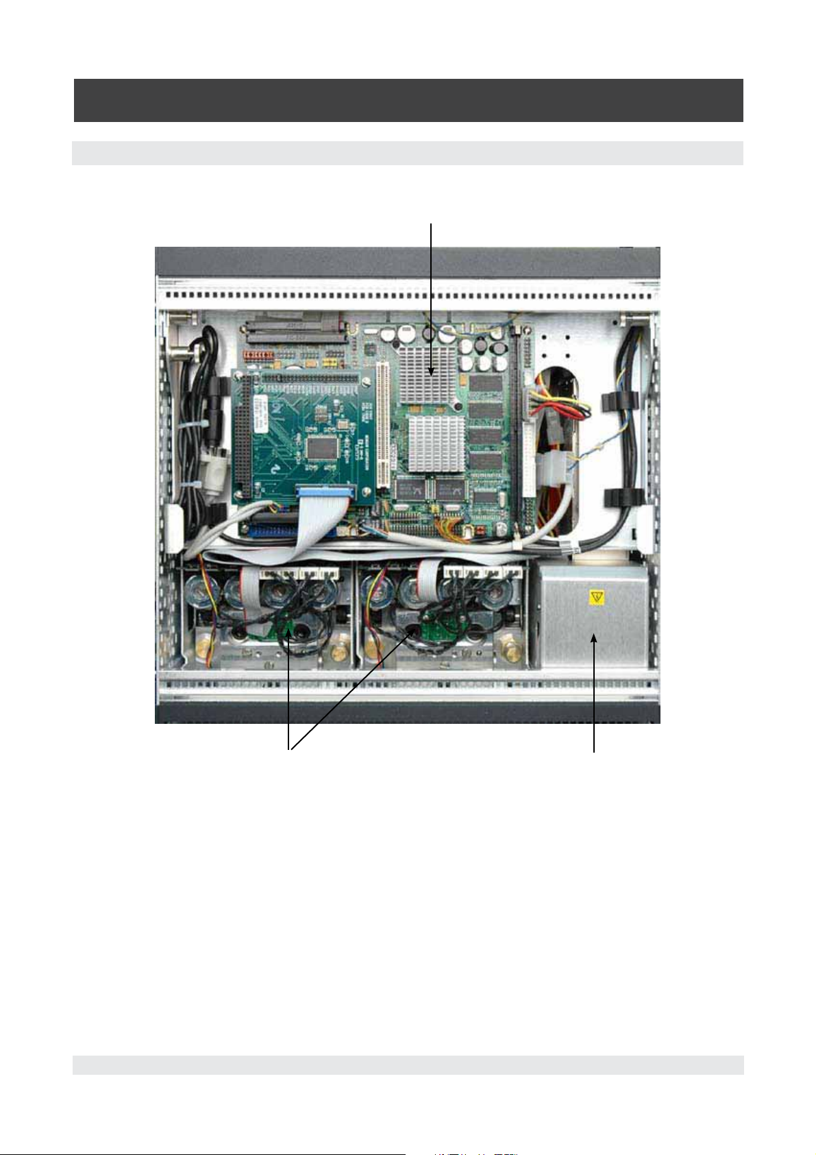
9.5 Chassis Interior
Automated Pressure Calibrator
CPC 6000
Electrical Module
Pneumatic Modules
Power Supply
Figure 9.5A - Chassis Interior, Top View
Mensor/WIKA Operating Instructions - CPC 6000 87
Page 88

Automated Pressure Calibrator
CPC 6000
Figure 9.5B - Chassis Interior, Front View
88 Mensor/WIKA Operating Instructions - CPC 6000
Page 89

10. Calibration
10.1 General
Automated Pressure Calibrator
CPC 6000
The CPC 6000 automatically adjusts the pressure reading for the effects of temperature and non-lin
earity within the calibrated temperature range of 15-45°C. The process is referred to as dynamic com
pensation because each reading is so adjusted before it is output to the display or to a communication
bus. Thus, a calibrated CPC 6000 operated within its temperature band, and with proper zero and
span adjustments, will provide accurate pressure measurements.
10.2 Environment
For maximum accuracy, allow the CPC 6000 to warm up for a minimum of 15 minutes in an ambient
temperature within the compensated range prior to commencing a calibration. In addition the instru
ment should be at rest on a stable platform that is free of excessive vibration and shock.
10.3 Pressure Standards
Mensor recommends the use of appropriately accurate primary pressure standards when calibrating
this instrument. Such standards should be sufficient so that when the techniques of the ISO Guide to
the Expression of Uncertainty in Measurement (GUM) are applied, the instrument meets its accuracy
statements as required by ISO/IEC 17025:2005, or other applicable standards.
10.4 Media
The recommended calibration medium is dry nitrogen or clean dry instrument air. A height variation
between the standard and the CPC 6000 can cause significant errors. See “
rection” for further information.
10.9 - Head Pressure Cor-
-
-
-
10.5 Calibration Setup
Figure 10.5 - Calibration Setup illustrates a typical setup for either local or remote calibration for an
absolute or gauge pressure instrument. In the illustration the ‘Optional Computer’ is required only for
performing a remote calibration.
The ‘Pressure Standard’ is normally a deadweight test instrument, and the ‘Volume Controller’ refers to
a hand operated variable-volume pressure vernier device. A diaphragm type vacuum gauge is recom
mended over the gauge tube type of vacuum sensor for calibrating sub-atmospheric pressures (see
Figure 10.5 under “Setup for Absolute Pressure”). A vacuum source with a capacity of generating 600
millitorr is recommended.
Mensor/WIKA Operating Instructions - CPC 6000 89
-
Page 90
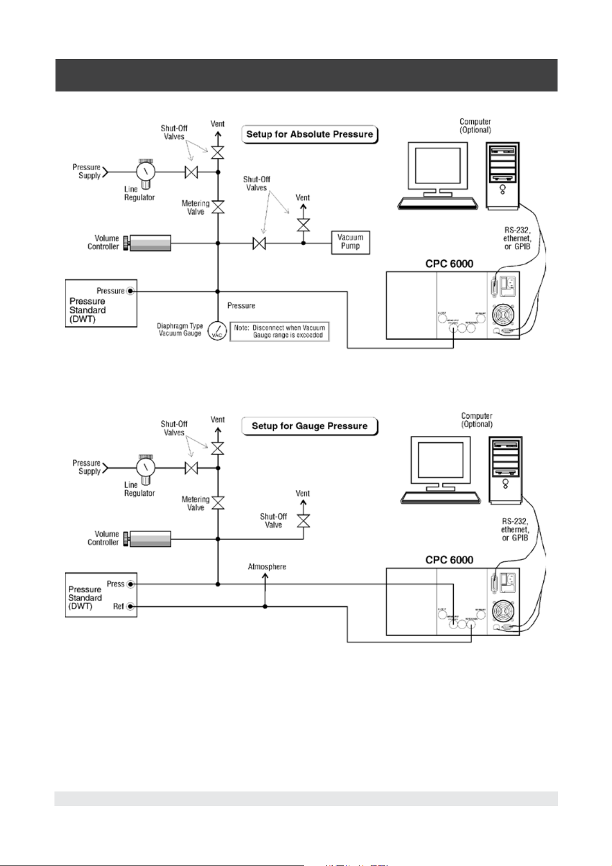
Automated Pressure Calibrator
CPC 6000
Figure 10.5 - Calibration Setup
90 Mensor/WIKA Operating Instructions - CPC 6000
Page 91

Automated Pressure Calibrator
CPC 6000
To get to the Calibration screen press [Setup], [Sensor], and then press [Calibrate].
10.6 Password
Autozero does not require a password, however one is needed to change any date of calibration, Zero,
Span, or to change the system password. The password installed at the factory was 1 2 3 4 5 6, but
the user can change this as described below.
10.6.1 Change Password
To change the current password:
1. Press the [Calibrate] key to see the Calibration Data screen similar to Figure 10.6.1A. Notice the
padlock.
Figure 10.6.1A - Calibration Data Screen (locked)
2. Touch the [Unlock] key to display the Enter Password window as shown in Figure 10.6.1B.
Figure 10.6.1B - ‘Enter Password’ Window
Mensor/WIKA Operating Instructions - CPC 6000 91
Page 92

Automated Pressure Calibrator
CPC 6000
3. Enter the current password. As each number is pressed an ‘*’ appears in the ‘Password’ window.
When completed touch [OK] to unlock the calibration data screen.
4. The Calibration Data screen of Figure 10.6.1C is displayed. Use this screen to change the password
to perform functions for 1 point calibration, 2 point calibration, restore factory cal, and head correc
tion. Touch [Change Password] and the Change Password window appears as in Figure 10.6.1D.
-
Figure 10.6.1C - Calibration Data Screen (unlocked)
Figure 10.6.1D - “Change Password” Window
5. At the Change Password screen enter from one to six digits for a new password. As each number
is pressed it appears in the Password window.
6. Before proceeding, review the displayed digits for accuracy. A mistake here could prevent future
access to this screen. To make a correction use [CE] to backspace through the entries and then im
mediately re-enter the correct numbers.
-
CAUTION: The password is seldom used and is easily forgotten. After a change
write down and save the new number. If the password is lost, contact Mensor.
!
Caution
92 Mensor/WIKA Operating Instructions - CPC 6000
Page 93

Automated Pressure Calibrator
CPC 6000
7. When satisfied that the new password is correct, and a written copy has been stored, press [OK]
to complete the entry. The previous password is immediately replaced by the new one.
8. Confirm that the new password is valid by pressing [Main], then repeat steps 1 through 3 to return
to the Calibration Data screen (Figure 10.6.1C). If this screen can’t be accessed using either the old
or the new password contact Mensor.
10.7 Restoring a Mensor Calibration
The offset and slope values established for each turndown at the final factory calibration are stored in
permanent memory within each transducer. These factory values can be restored at any time regard
less of the number of subsequent calibrations. To restore the factory calibration to the active turn
down, press [Restore Factory Cal] on the unlocked Data Entry screen seen in Figure 10.6.1C. This will
restore both the factory zero offset and slope calibration values to the active turndown. The [Restore
Factory Cal] function can be repeated for each turndown as desired.
10.8 On-site Calibration
-
-
The CPC 6000 can contain one primary transducer and barometric reference and may have an addi
tional, secondary transducer. Each transducer (except the Barometric Reference Transducer) can have
up to two separately calibrated ranges (two turndowns). Zero and span adjustments are available for
each of these turndowns.
Linearity is preset at the factory and is not adjustable. One and two point calibrations are used to
make a linear correction to the pressure readings using the formula: (uncorrected reading) X slope) +
offset. The one point calibration adjusts the offset, the two point calibration adjusts both the offset and
the slope.
10.8.1 CPC 6000 Preparation Procedure
The following is a step-by step instruction for calibrating a selected turndown.
Evacuate the pressure transducer(s) to a low pressure that will still maintain a viscous flow, typically
600 millitorr (0.0116 psi). At pressures lower than this the pressure at any particular point in the sys
tem is questionable. Allow from five to ten minutes for the target pressure to stabilize, then convert the
millitorr reading to an equivalent instrument reading in the active measurement units. Table 11.3 in the
Appendix Section lists millitorr conversion factors.
To begin a calibration, press the [Calibrate] tab and unlock the calibration screen as described in the
previous section. Select the turndown to calibrate from the drop list and the units in which to perform
the calibration on the unlocked calibration data screen.
10.8.2 [Calibrate] Setup Key
The Calibration screen shown in Figure 10.8.2A is the first of several screens relating to the calibration
functions. This screen allows the user to perform any of the following tasks:
1. Calibrate zero and span values on any turndown open of all installed sensors. An Absolute CPC
6000 allows calibration of the barometric reference transducer;
2. Establish a new Date of Calibration (DOC) for any turndown;
Mensor/WIKA Operating Instructions - CPC 6000 93
Page 94

Automated Pressure Calibrator
CPC 6000
3. Change the system password;
4. Autozero all turndowns at one time.
Notice the padlock icon on the display. This signifies that the indicated values on the screen are not
able to be modified until the password has been entered.
[Unlock] Key: Touch [Unlock] (Figure 10.8.2A) to move on to the password screen. This function is
password protected. Details on this function are included in the
Calibration section.
Figure 10.8.2A - Calibration Screen (locked) Figure 10.8.2B - Calibrate Screen (unlocked)
[Autozero] Key: Press this key to have the CPC 6000 automatically re-zero all turndowns that can
measure the vented pressure (Figure 10.8.2C).
Figure 10.8.2C - [Autozero] Key Figure 10.8.2D - Autozero Window
For an absolute CPC 6000, this automatic function will:
1. Vent the system.
2. Select the turndown with the smallest span that can measure the vented pressure, or read the inter
nal barometric reference if installed.
3. Record that pressure as “current barometric pressure”.
4. Adjust the zero offset of each turndown so the turndown’s output equals the “current barometric
pressure”.
-
94 Mensor/WIKA Operating Instructions - CPC 6000
Page 95

Automated Pressure Calibrator
CPC 6000
For a gauge CPC 6000, this automatic function will:
1. Vent the system.
2. Adjust the zero offset of each turndown that can measure the vented pressure so the turndown’s
output is equal to zero.
The autozero function re-zeros sensors without storing the zero offsets through
i
Notice
10.8.3 1-Point Calibration
A one-point calibration adjusts only the offset of the active turndown. From the unlocked calibration
data screen, press the [1 Point Calibration] key shown in Figure 10.8.3A. The ‘1 Point Cal’ window
shown in Figure 10.8.3B will appear. This window shows the maximum and minimum acceptable
values and the current reading. The [?] key pops up a help dialog with instructions on how to use this
screen. Enter the current known pressure in the ‘Desired Reading’ data window. Values entered that
are outside of the displayed Maximum/Minimum limits will not be accepted. When the desired reading
is displayed in the data window press the [OK] key and the offset will be stored. The [Cancel] key will
exit this window and not make any adjustments to the calibration of the active turndown.
power cycling.
Figure 10.8.3A - [1 Point Calibration] Key Figure 10.8.3B - 1 Point Cal Window
Mensor/WIKA Operating Instructions - CPC 6000 95
Page 96

Automated Pressure Calibrator
CPC 6000
10.8.4 2-Point Calibration
A two-point calibration adjusts both the offset and the slope of the active turndown. The low point
must be within 20% of the minimum range of the active turndown and the high point must be within
20% of the maximum range of the active turndown. Insure that the head correction is adjusted prop
erly, see
as shown in Figure 10.8.4A. The ‘Low Point Cal’ window illustrated in Figure 10.8.4B will appear. This
window shows the maximum and minimum acceptable values and the current reading. The [?] key
pops up a help dialog with instructions on how to use this window. Enter the current known pressure
in the ‘Desired Reading’ data window and press the [OK] key.
Section 10.9. From the unlocked calibration data screen, press the [2 Point Calibration] key
-
Figure 10.8.4A - [2 Point Calibration] Key Figure 10.8.4B - Low Point Cal Window
The ‘High Point Cal’ window illustrated in Figure 10.8.4C will appear. It’s function is identical to the
‘Low Point Cal’ window. Enter the new known pressure and press the [OK] key.
The [Cancel] key will exit either window and not make any adjustments to the calibration of the active
turndown.
The ‘Date of Calibration’ window illustrated in Figure 10.8.4D will appear. Enter the date of calibration
in a mm/dd/yyyy format exactly, including the ‘/’ separation marks. Press the [OK] key and the new
data of calibration will be saved to the turndown.
Figure 10.8.4C - High Point Cal Window Figure 10.8.4D - Date of Calibration Window
96 Mensor/WIKA Operating Instructions - CPC 6000
Page 97

10.9 Head Pressure Correction
Automated Pressure Calibrator
CPC 6000
The correction is accessed from the calibration menu. Four parameters may be set to reflect condi
tions at the operator’s site. Press either [English] or [Metric] units for entering head pressure correction
information into the CPC 6000. See Figure 10.9A.
Head correction parameters are stored separately for each channel.
-
i
Notice
Height: Enter the difference in height between the center of the measure/control port of the CPC 6000
and the reference level of the Device Under Test (DUT). If the reference level of the DUT is lower than
the center of the measure/control port of the CPC 6000, enter a positive height. If it is higher, enter a
negative height. See Figure 10.9B.
Figure 10.9A - Head Correction Screen Figure 10.9B - Height Window
Gas Density: If nitrogen (N2) or dry air are being used as a pressure media, press the appropriate
selection. If another gas is being used, enter the density for the gas at standard pressure and tempera
ture in either lb/cubic foot (english) or kg/liter (metric) units. See Figure 10.9C.
Gas Temperature: Enter the average gas temperature in degrees F or C. If unsure of the gas temperature, use 68 F. See Figure 10.9D.
Figure 10.9C - Gas Density Figure 10.9D - Gas Temperature
-
Mensor/WIKA Operating Instructions - CPC 6000 97
Page 98

Automated Pressure Calibrator
CPC 6000
Local Gravity: Enter the local gravity acceleration value. If unsure, use the standard gravity radio but-
ton. See Figure 10.9E.
Figure 10.9E - Local Gravity
Table 10.9 - Head Pressure Correction Limits
Height ±1200 inches
Density 0 to 1 lb/cu ft
Temperature 0 to 120 °F
Gravity 32 to 32.4 ft/sec²
98 Mensor/WIKA Operating Instructions - CPC 6000
Page 99

Automated Pressure Calibrator
CPC 6000
11. Appendix
11.1 Measurement Units
The Units command selects the measurement units to be output on the bus and the display.
Table 11.1 – Measurement Units (unitno)
Code Description Output Format
1 pounds per square inch PSI
2 inches of mercury @ 0°C inHg 0°C
3 inches of mercury @ 60°F inHg 60°F
2
2
2
ftSW
cmH
TSF
%FS
O 4°C
2
O 20°C
2
O 60°F
2
O 4°C
O 20°C
O 60°F
O 4°C
2
O 4°C
2
O 4°C
2
2
2
2
4 inches of water @ 4°C inH
5 inches of water @ 20°C inH
6 inches of water @ 60°F inH
7 feet of water @ 4°C ftH
8 feet of water @ 20°C ftH
9 feet of water @ 60°F ftH
10 millitorr mTorr
11 inches of seawater @ 0°C 3.5% salinity inSW
12 feet of seawater @ 0°C 3.5% salinity
13
14
atmospheres ATM
bars Bar
15 millibars mBar
16 millimeters of water @ 4°C mmH
17 centimeters of water @ 4°C
18 meters of water @ 4°C MH
19 millimeters of mercury @ 0°C mmHg 0°C
20 centimeters of mercury @ 0°C cmHg 0°C
21
torr Torr
22 kilopascals kPa
23 pascals PA
24 dyne per square centimeter Dy/cm
25 grams per square centimeter gm/cm
26 kilograms per square centimeter kg/cm
27 meters of seawater @ 0°C 3.5% salinity MSW
28 ounce per square inch OSI
29 pounds per square foot PSF
30 tons per square foot
31 percent of full scale
32 micron HG @ 0°C μHg 0°C
33 ton per square inch TSI
34 n/a n/a
Mensor/WIKA Operating Instructions - CPC 6000 99
Page 100

Automated Pressure Calibrator
CPC 6000
35 hectopascals hPa
36
37 millimeters of water @ 20°C mmH
38 centimeter of water @ 20°C cmH
39 meters of water @ 20°C
n/a User Units 1 User defined
n/a User Units 2 User defined
11.2 Conversion Factors, PSI
megapascals MPa
MH
O 20°C
2
O 20°C
2
O 20°C
2
The values listed in the column “To convert from PSI” are the values imbedded in the instrument pro
gram. The values listed under “To convert to PSI” are internally calculated approximations based on
the imbedded values.
Table 11.2 – Conversion Factors, PSI
Code Pressure Unit To convert from PSI To convert to PSI
1 PSI 1 1
2 inHg 0°C 2.036020 0.4911544
3 inHg 60°F 2.041772 0.4897707
4 inH
5 inH
6 inH
7 ftH
8 ftH
9 ftH
10 mTorr 51715.08 0.00001933672
11 inSW 0°C 3.5% salinity 26.92334 0.03714250
12 ftSW 0°C 3.5% salinity 2.243611 0.445710
13
14
15
16 mmH
17
18 MH
19 mmHg 0°C 51.71508 0.01933672
20 cmHg 0°C 5.171508 0.1933672
21
22 kPa 6.894757 0.1450377
23 PA 6894.757 0.0001450377
24 Dy/cm
25 gm/cm
26
O 4°C 27.68067 0.03612629
2
O 20°C 27.72977 0.03606233
2
O 60°F 27.70759 0.03609119
2
O 4°C 2.306726 0.4335149
2
O 20°C 2.310814 0.4327480
2
O 60°F 2.308966 0.4330943
2
ATM 0.06804596 14.69595
Bar 0.06894757 14.50377
mBar 68.94757 0.01450377
O 4°C 703.0890 0.001422295
2
O 4°C 70.30890 0.01422295
cmH
2
O 4°C 0.7030890 1.422295
2
Torr 51.71508 0.01933672
kg/cm
2
2
2
68947.57 0.00001450377
70.30697 0.01422334
0.07030697 14.22334
-
100 Mensor/WIKA Operating Instructions - CPC 6000
 Loading...