

Page 1

Operating Instructions
Pneumatic High-Speed Pressure Controller
CPC3000
Pneumatic High-Speed Pressure Controller Model CPC3000 Version 1.1
Page 2
Pneumatic High-Speed Pressure Controller CPC3000
Warning
Caution
Notice
This Warning symbol indicates that danger of injury for persons and the
environment and/or considerable material damage (mortal danger, danger
of injury) will occur if the respective safety precautions are not taken.
This Caution symbol indicates danger for the system and material if the
respective safety precautions are not taken.
This Notice symbol does not indicate safety notices but information for a
better understanding of the facts.
11498171.01 08/2009 GB
WIKA Operating Instruction Pneumatic High-Speed Pressure Controller ∙ Version 1.12
Page 3

Pneumatic High-Speed Pressure Controller CPC3000
Contents
1. General notices 5
1.1 FCC Radio frequency emission notice
1.2 Software license agreement
1.3 Accreditations
1.4 Packaging for Shipment
2. Safety notices 7
2.1 User Responsibilities
2.2 General safety notices
2.3 Safety notices regarding operation
3. Product description 10
3.1 Proper use
3.2 Features
3.3 Turning on the CPC3000
3.4 Front panel
3.5 Main menu
3.5.1 Keys, Tabs, Check Boxes, Labels/Graphics
3.6 Front Panel Variations and Navigation
3.6.1 Operating modes
3.7 Main menu setpoint entry options
4. Specifications 17
5. Installation 18
5.1 Introduction
5.2 Unpacking of the system
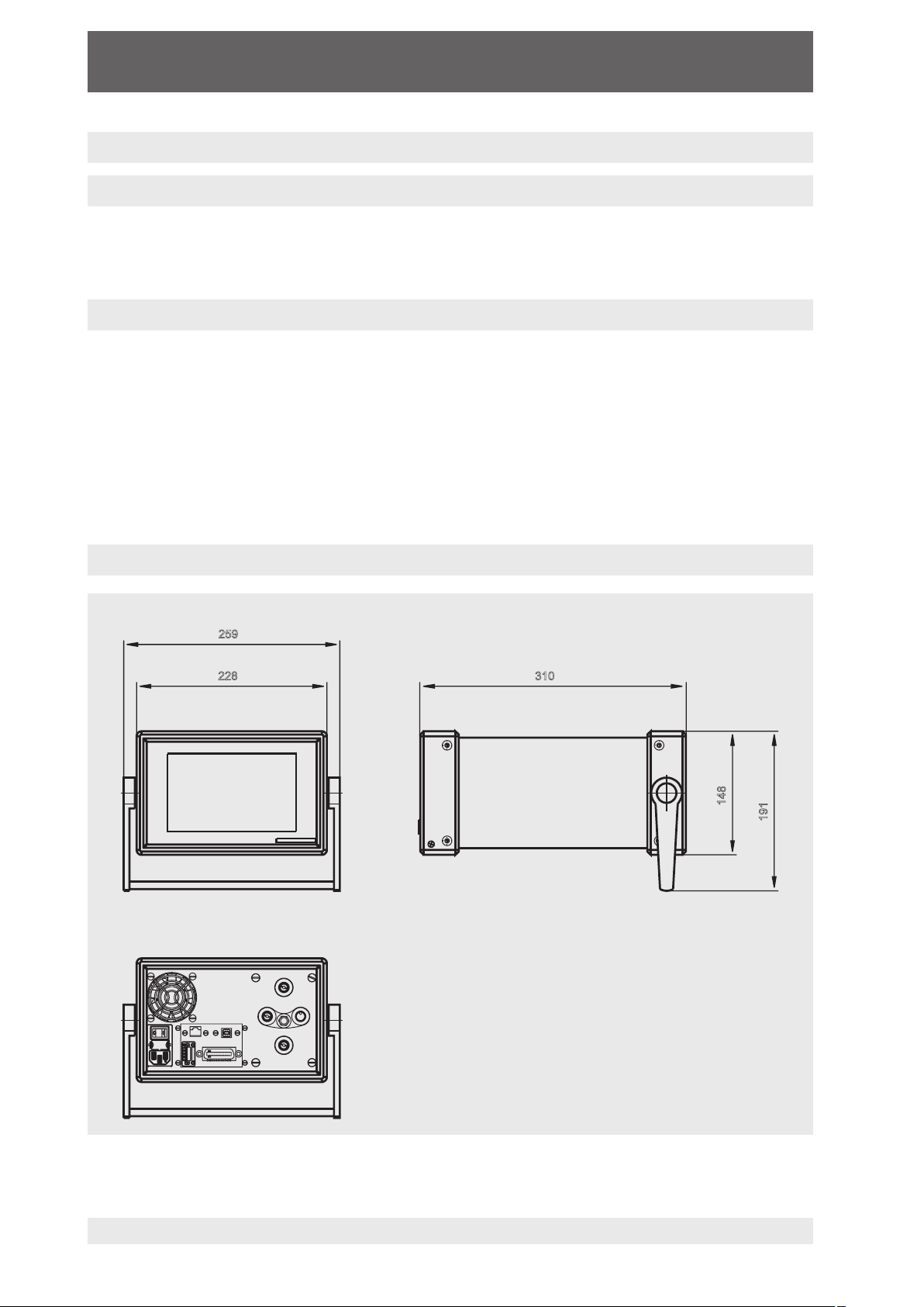
5.3 Dimensions of the available version in mm
5.4 Installation of the system
5.5 Rear panel
5.6 Pressure connections
5.7 Function of pressure connections
5.8 Electrical connections
5.8.1 Connecting the power supply and turning on the instrument
5.8.2 Connecting the Communications interfaces
6. Starting operation 23
7. Operation via Touch-screen 24
7.1 Setting the operating language
7.2 Display configuration
7.3 Setpoint Entry
7.4 Operating modes
7.5 Data Entry
7.6 Pressure unit, Pressure mode and Emulation mode
7.7 Bar Chart
11498171.01 08/2009 GB
6
6
6
7
7
7
8
10
11
12
12
13
13
14
14
16
18
18
18
19
20
20
21
22
22
22
24
24
26
27
30
30
31
WIKA Operating Instruction Pneumatic High-Speed Pressure Controller ∙ Version 1.1 3
Page 4

Pneumatic High-Speed Pressure Controller CPC3000
7.8 SETUP Menus
7.8.1 SETUP Display
7.8.2 SETUP Control
7.8.3 SETUP Remote
7.8.4 SETUP Info
7.8.5 SETUP Service
8. Remote Operation 40
8.1 Remote SETUP
8.2 Remote SETUP - Ethernet
8.3 Remote SETUP - USB
8.4 Remote SETUP - IEEE-488
8.5 Remote Command Set
8.5.1 Mensor Command Set
8.5.2 PCS 400 Commands Emulated
8.5.3 PCS 200 Commands Emulated
8.5.4 DPI 510 Commands Emulated
8.5.5 IEEE 488.2 Commands
8.5.6 SCPI Commands
9. Trouble-shooting measures 56
9.1 Table: Fault description and measures
10. Re-calibrating and servicing 58
11. Removal of the system 59
12. Transport of the system 60
13. Storage of the system 61
14. Placing out of service 62
15. Appendix 63
1. Table - Measurement Units
2. Table - Conversion factors, Pascal
31
32
33
34
35
36
40
41
41
42
42
43
48
50
52
52
53
56
64
65
11498171.01 08/2009 GB
WIKA Operating Instruction Pneumatic High-Speed Pressure Controller ∙ Version 1.14
Page 5

Pneumatic High-Speed Pressure Controller CPC3000
1. General notices
In the following chapters detailed information on the pneumatic high-speed pressure control-
ler model CPC3000 and its proper use can be found.
Should you require further information, or should there be problems which are not dealt with
in detail in the manual, please contact the following address:
WIKA Alexander Wiegand SE & Co. KG
Alexander Wiegand Strasse
D-63911 Klingenberg
Tel. +49 - (0) 93 72 / 132-9986
Fax +49 - (0) 93 72 / 132-217
E-mail: testequip@wika.de
All integrated pressure sensors are calibrated.
The warranty period for the pneumatic high-speed pressure controller model CPC3000 is 24
months according to the general terms of supply of ZVEI.
All guarantee claims lapse if the system is put to improper use or if the operating instructions
are not observed or if an attempt is made to open the system.
We also point out that the contents of these operating instructions does not form part of an
earlier or existing agreement, assurance or legal relationship or is meant to change these. All
obligations of WIKA Alexander Wiegand SE & Co. KG result from the respective sales contract
and the general business terms of WIKA Alexander Wiegand SE & Co. KG.
WIKA is a registered trade mark of WIKA Alexander Wiegand SE & Co. KG. All other brand
and product names are trademarks or registered trademarks of their respective companies.
We reserve the right to effect reasonable changes on the basis of technical improvements.
Any reproduction of this manual or parts thereof by any means is prohibited.
Version key regarding firmware and respective manual
Manual Firmware
V1.1 V 1.0
© 2009 Copyright WIKA Alexander Wiegand SE & Co. KG.
11498171.01 08/2009 GB
WIKA Operating Instruction Pneumatic High-Speed Pressure Controller ∙ Version 1.1 5
Page 6

Pneumatic High-Speed Pressure Controller CPC3000
1.1 FCC Radio frequency emission notice
This equipment has been tested and found to comply with the limits for a Class A digital
device, pursuant to Part 15 of the FCC Rules. These limits are designed to provide reasonable protection against harmful interference when the equipment is operated in a commercial
environment. This equipment generates, uses, and can radiate radio frequency energy and, if
not installed and used in accordance with the instruction manual, may cause harmful interfer-
ence to radio communications. Operation of this equipment in a residential area is likely to
cause harmful interference in which case the user will be required to correct the interference
at his or her own expense.
Use shielded cables to connect external devices to this instrument to minimize
rf radiation.
Notice
1.2 Software license agreement
This product contains intellectual property, i.e., software programs, that are licensed for use
by the end user/customer (hereinafter “end user”).
This is not a sale of such intellectual property.
The end user shall not copy, disassemble or reverse compile the software program.
The software programs are provided to the end user “as is” without warranty of
any kind, either express or implied, including, but not limited to, warranties of
merchantability and fitness for a particular purpose. The entire risk of the quality
Notice
and performance of the software program is with the end user.
WIKA, Mensor and its suppliers shall not be held to any liability for any damages
suffered or incurred by the end user (including, but not limited to, general,
special, consequential or incidental damages including damages for loss of
business profits, business interruption, loss of business information and the
like), arising from or in connection with the delivery, use or performance of the
software program.
1.3 Accreditations
WIKA is registered to ISO 9001:2000. The calibration program at WIKA is accredited by DKD,
as complying with both the ISO/IEC 17025:2005 standards. All Mensor primary standards are
traceable to PTB.
11498171.01 08/2009 GB
WIKA Operating Instruction Pneumatic High-Speed Pressure Controller ∙ Version 1.16
Page 7

Pneumatic High-Speed Pressure Controller CPC3000
1.4 Packaging for Shipment
If the product must be shipped to a different location or returned to WIKA for any reason
through a common carrier it must be packaged properly to minimize the risk of damage.
The recommended method of packing is to place the instrument in a container, surrounded on
all sides with at least 10 cm of shock attenuation material such as styrofoam peanuts.
2. Safety notices
2.1 User Responsibilities
To ensure safety, the user must make sure that:
The system is used properly (refer to 3.1 "Proper use" in the chapter 3. "Product descrip-
tion"), no dangerous media are used and that all technical specifications are observed.
Safety mechanisms exist, which exclude any danger to persons or machinery through
improper pressurisation.
The system is only operated in perfect operative condition.
This operation manual is legible and accessible to the user at the system's location.
The system is operated, serviced and repaired only by staff which is authorised and quali-
fied to do so.
The operator receives instruction on industrial safety and environmental protection, and is
knowledgeable of the operating instructions and the safety notices contained therein.
2.2 General safety notices
The system should only be operated by trained personnel who are familiar
with this manual and the operation of the instrument.
Caution
A condition for trouble-free and safe operation of this system is proper
transport, proper storage, installation, assembly and proper use as well as
careful operation and maintenance.
Warning
11498171.01 08/2009 GB
WIKA Operating Instruction Pneumatic High-Speed Pressure Controller ∙ Version 1.1 7
Any operation not described in the following instructions should be prohibited.The system must be handled with the care required for an electronic
precision instrument (protect from humidity, impacts, strong magnetic
fields, static electricity and extreme temperatures). Do not insert any
objects into the instrument.
The system is powered via the power cable with a voltage that can cause
physical injury. Even after disconnecting the system from the power
supply, dangerous voltages can temporarily occur due to capacitance.
Page 8

Pneumatic High-Speed Pressure Controller CPC3000
Extreme care must be taken with pressure connections when using
hazardous or toxic media.
Warning
Repairs must only be performed by authorized service personnel.
Additional safety notices are found throughout this manual.
2.3 Safety notices regarding operation
HIGH PRESSURE! High pressure gases are potentially hazardous. Energy
stored in these gases can be released suddenly and with extreme force.
High pressure systems should be assembled and operated only by person-
Warning
nel who have been trained in proper safety practices.
POSSIBLE INJURY! The tubing, valves and other apparatus attached to
the controller must be adequate for the maximum pressure which will be
applied, otherwise physical injury to the operator or bystander is possible.
Caution: use the proper pressure medium. Use only clean, dry non-corrosive gases. This instrument is not designed for oxygen use.
Caution
The user must use caution when controlling from a very high pressure
down to a very low pressure when a vacuum pump is connected to the
Vacuum/Exhaust port. Large volumes of gas may be present in the device
Warning
under test and will exhaust through the Vacuum/Exhaust port in excess
of the capacity of the internal relief valve, possibly causing damage to the
vacuum pump.
Caution
Warning
HIGH SOUND LEVELS! Pressures from 40 bar and up can generate sound
levels above 100 db for brief periods when they are exhausted directly to
atmosphere. If no muffling devices are attached to the VACUUM/EXHASUT
or VENT port, then ear protection is advised for personnel in the vicinity of
the instruments that will be operated under such conditions.
NOT EXPLOSION PROOF! Installation of this instrument in an area requiring devices rated as intrinsically safe is not recommended.
Caution: ESD protection required.
The proper use of grounded work surfaces and personal wrist straps are
required when coming into contact with exposed circuits (printed circuit
boards) to prevent static discharge damage to sensitive electronic components.
Before the system is switched on, the user must verify that the system was
installed correctly and that all connections meet current regulations.
The user must ensure that all specifications such as supply voltage,
operating temperature, humidity, sensor-specific pressure media and
pressure ranges are observed.
WIKA Operating Instruction Pneumatic High-Speed Pressure Controller ∙ Version 1.18
11498171.01 08/2009 GB
Page 9

Pneumatic High-Speed Pressure Controller CPC3000
Before pressurizing, the user must ensure through appropriate protective
measures that the system or the device will not be overpressurized. When
working with or on an instrument, safety glasses should be worn.
Warning
In areas where the system is operated there must be sufficient air ventilation due to inert gases that will escape during use.
High pressure can accelerate parts in a manner that could be hazardous
and cause physical injury.
Additional warning and caution notes are included throughout this manual.
11498171.01 08/2009 GB
WIKA Operating Instruction Pneumatic High-Speed Pressure Controller ∙ Version 1.1 9
Page 10
Pneumatic High-Speed Pressure Controller CPC3000
3. Product description
3.1 Proper use
The Pneumatic High-Speed Controller model CPC3000 is a bench top or rack mounted Digital
Pressure Calibrator/Controller used for test and calibration of mechanical pressure gauges,
pressure switches, sensors, transducers, transmitters and any pressure related devices where
time to set point is the most critical requirement.
Only dry clean air or nitrogen should be used as the pressure medium.
Shop air should be avoided and corrosive, oxidizing, condensing, explosive
gasses should be strictly avoided.
Warning
The maximum permissible supply pressure at the SUPPLY port should be
10 % over full scale value of the sensor installed.
Very fast pressure changes can damage the sensor, due to mechanical
stress on the sensor; especially if the fast pressure change leads to an
internal pressure which is higher then the full scale of the internal sensor
(even if it is only for a fraction of a second). In some cases, the internal
relief valves cannot react quickly enough to protect the sensor.
Notice
Warning
The Internal pressure sensors have a calibration certificate (see enclosure:
calibration certificate) for the entire measuring chain.
The system is not suitable for use in areas with an explosion hazard.
If the CPC3000 is not used according to this manual, safe operation of the
system is not guaranteed.
The user of the system and not the manufacturer is responsible for all
personal and material damage resulting from improper use!
11498171.01 08/2009 GB
WIKA Operating Instruction Pneumatic High-Speed Pressure Controller ∙ Version 1.110
Page 11

Pneumatic High-Speed Pressure Controller CPC3000
3.2 Features
1. The CPC3000 will control (up scale or down
scale) into a 150 ml volume, to within
0.025 % of the set point, in 3 seconds or
less.
2. Accuracy of 0.025 % FS, one year calibra
-
tion interval.
3. Lightweight compact case with bezel and
handle or 19" rack mount kit.
4. Manual operation via the color touch screen
and easy access to auxiliary screens allow
quick changes to the set point using the
"STEP" and "JOG" screens.
5. Remote operation over IEEE-488, USB 2.0,
or Ethernet.
6. Emulation of other conventional controllers.
7. An optional internal high accuracy baromet
-
ric reference sensor for emulation of gauge
pressure and absolute pressure.
8. A large color SVGA LCD display with a
touch screen for intuitive operator interface.
9. Multiple languages.
11498171.01 08/2009 GB
WIKA Operating Instruction Pneumatic High-Speed Pressure Controller ∙ Version 1.1 11
Page 12
Pneumatic High-Speed Pressure Controller CPC3000
310
228
259
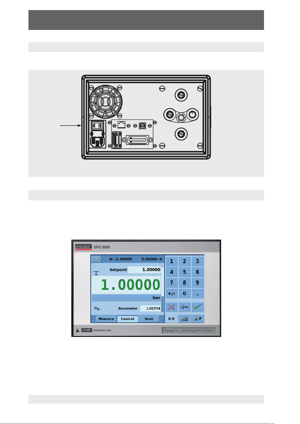
3.3 Turning on the CPC3000
The power switch is located on the rear of the instrument as shown in "Figure - Rear Panel".
Power Switch
Figure - Rear Panel
3.4 Front panel
The CPC3000 front panel (see above: "Figure - Front panel") includes a 7 inch colour SVGA
display featuring touch screen technology. Operator input is accomplished by pressing the
number, words or symbols presented on the display. There are no mechanical keypads or
switches on the front panel.
Figure - Front Panel
11498171.01 08/2009 GB
WIKA Operating Instruction Pneumatic High-Speed Pressure Controller ∙ Version 1.112
Page 13
Pneumatic High-Speed Pressure Controller CPC3000
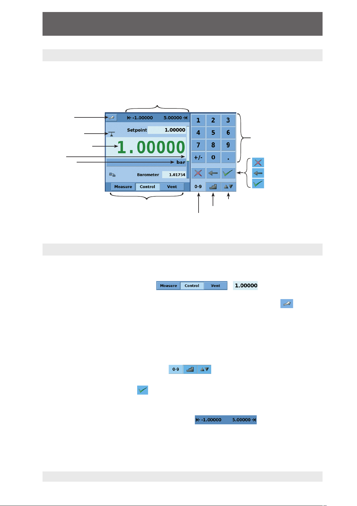
3.5 Main menu
When the CPC3000 is powered up it takes about one minute for initialization, then displays a
screen similar to the "Figure - Initial Screen" below.
User defined control range limits
(configurable via SETUP-CONTROL)
SETUP menu
Stability indication
Current pressure value
Bar graph
Pressure Units
Operating mode
JOG key pad selection tab
STEP key pad selection tab
Numeric key pad selection tab
Numeric keypad
Delete selected set point
Delete last entered digit
Accept selected set point
Figure - Initial Screen
3.5.1 Keys, Tabs, Check Boxes, Labels/Graphics
Keys: There are two types of keys: those that act as a switch to change a condition and
those that open a data entry screen when pressed. Keys have borders with a three dimensional, shadowed effect (examples: , ). Throughout this
manual keys are represented with the displayed characters enclosed in brackets (Example
[MEASURE] ) or a description and the actual graphic icon (Example [SETUP] ). Pressing a key will have one of the following results: 1) instant, single step response, 2) continuously repeating steps while the key is held down, 3) the key will change colors indicating
that the associated function is active or 4) a data entry dialog box will open. Operators will
quickly become accustomed to the particular characteristics of the frequently used keys.
Tabs: Tabs are analogous to tabs in a notebook that allow switching quickly between relat-
ed screens. Tabs are keys that allow the operator to switch between a group of screens that
have a similar purpose, for example the tabs allow the operator to quickly
switch between three screens used to enter the setpoint.
Check Boxes: Check Boxes allow for the inclusion or exclusion of specific elements or
conditions.
Labels and Graphics: Labels and Graphics are text, or graphic that display information,
but do not respond to being touched (examples: ). They indicate
choices that have been made in the SETUP menus or indicate existing conditions as
pressure is controlled or measured.
11498171.01 08/2009 GB
WIKA Operating Instruction Pneumatic High-Speed Pressure Controller ∙ Version 1.1 13
Page 14

Pneumatic High-Speed Pressure Controller CPC3000
3.6 Front panel variations and navigation
Bar Graph: The bar graph shows the relative indication of the range of the internal sensor, the
user defined limits on the internal sensor, the unused portion of the internal pressure sensor
range, the setpoint and the magnitude of the actual controlled pressure. The user defined
control limits can be selected in the MAIN -> [SETUP] -> CONTROL SCREEN and can be
set to correspond to the range of the device under test. It is important to note that when
the STEP key pad is active in percent mode each step is a percent of the user defined
limit not the full scale of the internal sensor. This is useful when calibrating or testing
various range devices. "Figure - Bar Graph" shows the bar graph when the CPC3000 is in
control mode controlling a pressure at the setpoint.
Bar graph shows relative indication of:
Range of the Internal sensor
User defined limits
Unused portion of the internal sensor range
Setpoint
Current pressure reading
Figure - Bar Graph
3.6.1 Operating modes
Press to select mode:
MEASURE
In MEASURE mode, the instrument measures the pressure connected to the MEASURE
port (on changing from CONTROL mode: the last controlled pressure will be held/sealed in
the connected test assembly).
CONTROL
In CONTROL mode the instrument provides a very precise pressure at the MEASURE port.
VENT
VENT opens MEASURE port to atmospheric pressure.
11498171.01 08/2009 GB
WIKA Operating Instruction Pneumatic High-Speed Pressure Controller ∙ Version 1.114
Page 15
Pneumatic High-Speed Pressure Controller CPC3000
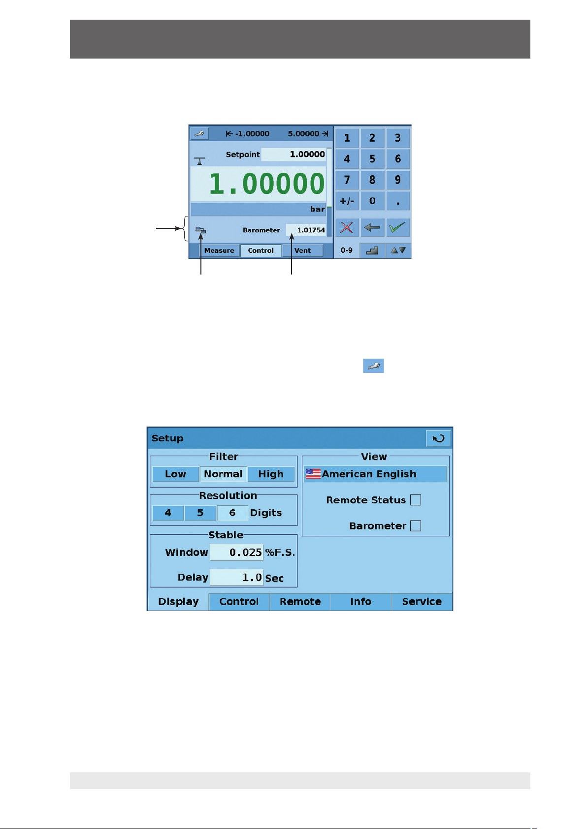
Optional elements can be chosen in the [SETUP-DISPLAY] screen explained in chapter 7.8.1
of this manual. Each optional element is displayed in the area below the pressure units.
Area for optional
elements
Communication status
Optional barometric reference display
Figure - Optional Display elements
Navigation to the SETUP screens is achieved pressing the Icon. SETUP "Figure -
SETUP Display Screen" shows the SETUP screen with the display table activated. Other
tabs at the bottom are used to navigate to additional SETUP screens. SETUP screens will be
discussed in detail in chapter 7.8 of this manual.
11498171.01 08/2009 GB
WIKA Operating Instruction Pneumatic High-Speed Pressure Controller ∙ Version 1.1 15
Figure - SETUP Display Screen
Page 16

Pneumatic High-Speed Pressure Controller CPC3000
3.7 Main menu setpoint entry options
Pressure setpoint entry options are chosen using the tab keys .
"Figure - Numeric Keypad" shows the main menu with the numeric keypad selected.
Figure - Numeric Keypad
"Figure - STEP Keypad" shows the main menu with the STEP keypad selected.
Figure - STEP Keypad
"Figure - JOG Keypad" shows the main menu with the JOG keypad selected.
Figure - JOG Keypad
WIKA Operating Instruction Pneumatic High-Speed Pressure Controller ∙ Version 1.116
11498171.01 08/2009 GB
Page 17

Pneumatic High-Speed Pressure Controller CPC3000
4. Specifications
Specifications CPC3000
Pressure ranges bar -1 ... +70 (depending on sensor)
Pressure types Absolute, gauge or bi-directional ranges
Precision % FS < 0.015
Accuracy % FS < 0.025
Pressure units 33 selectable and 2 freely definable
Control stability % FS < 0.004
Slew rate sec.
Control range % FS 0 up to 100
Test volume ccm 50 ... 1,000 (without throttle)
Pressure ports mm 4 ports with 7/16"- 20 F SAE. incl. 6 mm tube fitting adaptors
Filter elements 40 micron filter element included in each pressure port
Permissible pressure media clean dry non-corrosive gases
Wetted parts aluminium, brass, 316 and 316L stainless steel, Buna N, FPM/FKM,
Overpressure protection safety relief valve
Instrument version desk top/optional: incl. rack mounting kit
Screen 7.0" colour LCD with touch-screen
Resolution digits 4 ... 6
Internal measuring rate 1/sec 25
Display update 1/sec 4
Warm-up time min approx. 15
Digital Interface Ethernet, IEEE-488, USB
Command sentences Mensor, SCPI, others optional
Power Supply V AC 100 … 240, 50-60 Hz
Energy Consumption VA maximum 90
Permissible pressure
Supply port % FS ~ 110
Measure/Control port % FS max. 105
Permissible
Operating temperature °C 10 … 50
Storage temperature °C 0 ... 70
Air humidity % 0 … 95 (relative humidity without moisture condensation)
Operating position Horizontal or slightly tilted
Compensated temperature
range
Weight kg approx. 9.1
Dimensions mm see technical drawings
CE-mark Conformity certificate
Calibration* Incl. factory calibration certificate 3.1 per DIN EN 10 204
°C 15 …. 45
< 3 (with a sudden pressure increase of 10 % FS in a 150 ml test volume)
glass filled epoxy, RTV, Nylon, Ceramic
* Calibration in a horizontal position.
11498171.01 08/2009 GB
WIKA Operating Instruction Pneumatic High-Speed Pressure Controller ∙ Version 1.1 17
Page 18
Pneumatic High-Speed Pressure Controller CPC3000
310
148
191
228
259
5. Installation
5.1 Introduction
The initial installation of the CPC3000 includes the following steps: Unpack the system, place
it in a suitable workspace, connect it, switch it on and configure.
5.2 Unpacking the system
Unpack all components of the CPC3000 carefully and check the parts for damage. Report
any damage immediately to the forwarding agent.
Apart from any additional components ordered, a shipment consists of:
CPC3000 controller
¼" and 6 mm tube fitting adapters
Main cable
Manual with calibration certificates in the enclosure
Optional: recommend Interface cable or any other accessories ordered
5.3 Dimensions of the available version in mm
Front view Side view
Rear view
The instrument can be set up on a table top or it can be rack-mounted. Rack mount adapters
are optional on the CPC3000 and require an adapter panel.
WIKA Operating Instruction Pneumatic High-Speed Pressure Controller ∙ Version 1.118
11498171.01 08/2009 GB
Page 19

Pneumatic High-Speed Pressure Controller CPC3000
5.4 Installation of the system
The installation site must meet the following conditions:
Operating Temperature: 10 to 50 °C
Humidity: 0 to 95 % relative humidity non-condensation
Flat, horizontal location; secure fixed working surface (desk top model) or installation in a
19" rack mount.
At the back of the instrument sufficient air circulation must be provided for to avoid an
accumulation of the heat conducted to the outside via the fan.
During operation, pressure escapes through the VENT port in the back of the instrument.
Personnel should not have access to the rear VENT and EXHAUST port during operation.
Avoid the following influences:
Direct sunlight or proximity to hot objects
Unstable installation position
Mechanical vibration
Proximity to sources of strong electromagnetic fields, such as high tension appliances,
mobile telephones or mains
Soot, steam, dust and corrosive gases
Environment with explosion hazard, inflammable atmospheres
Pressure supply requirements:
Stable supply pressure 10 % higher than the full scale of the internal transducer
Permissible media: dry, clean air or nitrogen
Vacuum: min. 50 litres/min (if required)
An angle of inclination of the system of more than 3 degrees can cause a deviation in the measured pressure and should be avoided. Zeroing the unit at the
angle of inclination will nullify this deviation.
Notice
Applying supply pressure higher than the recommended pressure can
cause permanent damage to the control channel!
Warning
11498171.01 08/2009 GB
WIKA Operating Instruction Pneumatic High-Speed Pressure Controller ∙ Version 1.1 19
Page 20
Pneumatic High-Speed Pressure Controller CPC3000
310
228
259
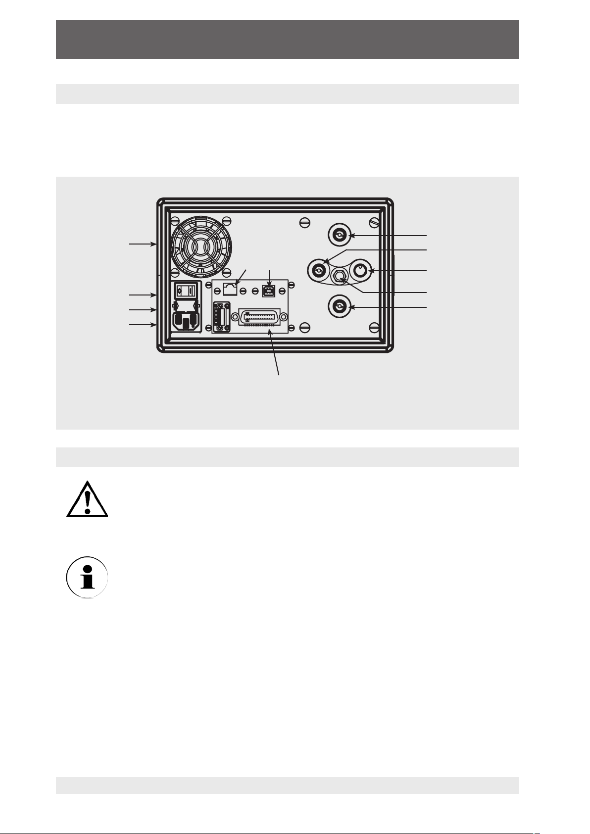
5.5 Rear panel
Four pneumatic pressure ports are located on the rear panel (see below: "Figure - Rear
panel"). Positioned on the left are the ethernet and RS-232 and GPIB connector, the off/on
switch, the line fuses, and a protective grill covering the ventilating fan.
Fan
Mains input socket
Micro fuse
Power supply
5.6 Pressure connections
The pressure connections must be installed according to the following
instructions, observing the relevant regulations. The installation should be
performed by persons familiar with, and who can work according to, the
Warning
safety regulations for working on pneumatic/hydraulic systems.
Ethernet USB
IEEE-488.2
Figure - Rear panel
Supply Port
Measure/Control Port
Reference Port
Vent
Exhaust/Vacuum Port
When making up a connection to an o-ring adapter port use a back-up wrench
to prevent over-stressing the threads in the manifold block.
Notice
All of the pressure ports on the rear are female 7/16 - 20 SAE/MS straight threads per
MS16142 and SAE J514 table 14.
They require a tube fitting boss seal with an o-ring per MS33656.
WIKA provides female 1/4 inch and 6 mm tube fittings with the instrument.
The pressure connections can be made to these adapters with the proper mating hardware.
Do not use sealant on fittings sealed with an o-ring.
WIKA Operating Instruction Pneumatic High-Speed Pressure Controller ∙ Version 1.120
11498171.01 08/2009 GB
Page 21

Pneumatic High-Speed Pressure Controller CPC3000
5.7 Function of pressure connections
MEASURE/CONTROL port
Below the label "MEASURE/CONTROL" is a pressure connection. In MEASURE mode
this connection connects the pressure applied to the internal sensor where the pressure
is measured (within the range of the internal sensor). In CONTROL mode this connection
supplies an output pressure controlled by the internal regulator at the commanded setpoint.
SUPPLY port
Below the label "SUPPLY" is a pressure connection. This connection should be supplied
with a pressure that is approximately equal to 110 % of the full scale pressure of the internal sensor. In other words, 10 % above the full scale pressure of the internal sensor
“SUPPLY Pressure” in the specifications chapter for supply pressure and pressure media
requirements.)
EXHAUST/VACUUM port
Below the label "EXHAUST/VACUUM" is a pressure connection.
If a sub-atmospheric control pressure is required a vacuum pump must be connected to
this port. Otherwise, this port may be left open to atmosphere.
(see
The user must use caution when controlling from a very high pressure
down to a very low pressure when a vacuum pump is connected to the
exhaust port. Large volumes of gas may be present in the device under
Warning
test and will exhaust through the EXHAUST/VACUUM port in excess of
the capacity of the internal relief valve, possibly causing damage to the
vacuum pump.
VENT outlet
Below the label "VENT" is the pressure outlet. In VENT mode the pressure within the system
is released through this outlet.
HIGH SOUND LEVELS! Pressures from 40 bar and up can generate sound
levels above 100 db for brief periods when they are exhausted directly to
atmosphere. If no muffling devices are attached to the EXHAUST/VACUUM
Warning
and VENT port, then ear protection is advised for personnel in the vicinity
of the instruments that will be operated under such conditions.
REFERENCE port
On gauge units this port is connected to the reference side of the transducer, and on
absolute units it is internally capped. This port is normally left open to atmosphere.
The controller must be protected from over pressure.
Warning
11498171.01 08/2009 GB
WIKA Operating Instruction Pneumatic High-Speed Pressure Controller ∙ Version 1.1 21
Pipes, couplings and other components used for connecting the supply
exhaust and the MEASURE/CONTROL port must be suitable for the application and rated for the applied pressures.
The user must ensure that the pressure media are clean and dry. If necessary, the internal sensors and mechanisms must be protected by using a
liquid trap or coalescing filter.
Page 22

Pneumatic High-Speed Pressure Controller CPC3000
5.8 Electrical connections
The electrical installation has to be carried out according to the following
instructions while observing the relevant regulations. It is to be carried out
by a qualified electrician.
Warning
5.8.1 Connecting the power supply and turning on the instrument
Before connecting the power supply, make sure that the mains voltage
agrees with the specification of the power unit. Switch off the system before
connecting the mains via the main switch at the rear of the instrument.
Warning
Only the mains cable supplied should be used.
The 3-pole mains cable supplied is fitted with an earth lead. You should
therefore operate the system only from a three-pin socket and always make
sure that the earth lead is properly connected.
The mains input socket is to be connected according to the regulations with the countryspecific connection cable supplied to a power supply that lies within the required specifica-
tion. To power-on the instrument switch the power switch ON (located on the rear of the
instrument; also see chapter "6. Starting operation").
5.8.2 Connecting the Communications interfaces
USB 2.0 FS Interface
The USB 2.0 FS connection on the rear panel of the CPC3000 is a USB-B Type connector.
The manufacturer of the USB interface board provides the drivers and product information on
a CD that is included with the CPC3000.
IEEE-488 Interface (GPIB)
The connection of the IEEE-488 interface is designed as a 24 pole IEEE-488-socket.
The manufacturer of the host IEEE-488 interface board provides software to allow communication between the board and various programming languages.
An interactive program for debugging is usually provided as well. Refer to the board manufacturer’s documentation for more information.
ETHERNET Interface
The ethernet communication port allows the CPC3000 to communicate with computers using
10/100 Based-T specifications.
11498171.01 08/2009 GB
WIKA Operating Instruction Pneumatic High-Speed Pressure Controller ∙ Version 1.122
Page 23

Pneumatic High-Speed Pressure Controller CPC3000
Please consult your Computer Resources Department prior to connecting
this instrument to your network to verify there are no conflicts with existing
IP addresses.
Warning
Ethernet communications are transmitted over a standard RJ-45 cable.
Prior to first time use of ethernet communication, the four parameters "IP", "Netmask",
"Gateway" and "Port" must be SETUP. These are configured in the communications SETUP
screen.
6. Starting operation
Before the system is switched on, verify that the system was installed
according to the instructions of the previous chapter and that all connections installed are fitted according to the current regulations.
Warning
Operators must ensure that all specifications that apply to supply voltage,
operating temperature, humidity, pressure media and pressure ranges are
observed.
Condensation can occur inside the system when the temperature changes
abruptly. Give the system sufficient time for acclimatisation in such cases.
Before pressurizing, the operator must ensure that the system and the
device under test will not be over pressurized. When working with or on
the instrument, safety glasses have to be worn.
In the rooms in which the CPC3000 is operated sufficient air ventilation has
to be ensured.
When the above points have been met you can switch on the system, (the switch is located
on the rear of the instrument) and configure it as required after you have familiarised yourself
with the operation (see chapter: "7. Operation via Touch-screen").
After turning the power switch to ON, the instrument will go through a brief initialization
process and system check, which will take about 40 seconds.
As soon as the system check is completed the system will default to an operating screen
similar to "Figure - Initial screen" in chapter 3.6.
Allow at least 15 minutes of warm up time to achieve thermal equilibrium between the controller and its environment before performing critical pressure measurements.
11498171.01 08/2009 GB
WIKA Operating Instruction Pneumatic High-Speed Pressure Controller ∙ Version 1.1 23
Page 24

Pneumatic High-Speed Pressure Controller CPC3000
7. Operation via Touch-screen
This chapter describes the procedures for operating the CPC3000 from the front panel.
Tabs, Keys, Value Entry and Check Boxes:
Local operation is accomplished by observing the data presented in the display menus,
then pressing the on-screen tab, key, value entry or check box for the desired sub-menu,
function or selection. Tabs are used to access the subset of a menu, keys open new menus,
make selections or change a parameter, value entry opens a keypad to enter a value, and
check boxes allow choice of associated display option.
Screen hierarchy:
Navigation within the CPC3000 is similar to a computer file system or a web page. Keys or
tabs activate sub-menus. Within the sub-menus there may be related sub-menus or selections. To return back through the hierarchy of screens the [BACK] key is provided.
Throughout this manual screen hierarchy will be designated using the following conven-
tion: "MAIN -> SUB-MENU -> SELECTION" or "MAIN -> SUB-MENU -> TAB -> SELECTION". The hierarchical menu structure is very intuitive and will become more obvious after
reviewing following examples.
7.1 Setting the operating language
In the upper left corner of the main display is the [SETUP] key . To change the language
select the SETUP key and select the [DISPLAY] tab if not already active. In the box labelled
"VIEW" on the upper right side of the resulting "MAIN -> SETUP -> DISPLAY" screen there is
a [FLAG] key. Press the [FLAG] key and a selection of language keys will appear. Select
the desired language. Then press the [BACK] key to return to the main menu which will now
display in the selected language. Using our convention, selecting English would be described
by the following: "MAIN -> SETUP -> DISPLAY -> FLAG -> ENGLISH".
7.2 Display configuration
The CPC3000 main menu "Figure - Main Menu" shows the main screen that appears when
the unit is turned on. A point by point description of each element is shown in this figure. The
[SETUP] key opens the SETUP menu where changes can be made and information
viewed. Each sub-menu in the SETUP menu can be activated by pressing the [DISPLAY],
[CONTROL], [REMOTE], [INFO] or [SERVICE] tab. Each of these SETUP sub-menus will be
discussed in detail in chapter 7.8.
The points on the main menu that are independent of the SETUP menus are the setpoint indication, the actual pressure reading, the units of measure and the control modes (MEASURE,
CONTROL and VENT), plus the three tab menus used for selecting a setpoint.
The [PRESSURE UNIT] key indicates the currently chosen pressure unit and can be pressed to
open a menu that allows selection of English, metric, or user defined pressure units.
The CPC3000 main menu shown in "Figure - Optional Elements" shows elements that can
be displayed on the main menu and describes the three choices available for setpoint entry
(Numeric keypad, STEP and JOG). Optional elements include the Communication status icon
which indicates a connection or disconnection from a remote computer, and the barometric
reference indication showing the value of the atmospheric pressure measured by the optional
internal barometric reference sensor.
WIKA Operating Instruction Pneumatic High-Speed Pressure Controller ∙ Version 1.124
11498171.01 08/2009 GB
Page 25

Pneumatic High-Speed Pressure Controller CPC3000
User defined DUT / control range
limits (configurable via SETUP)
SETUP menu
Setpoint
Stable indication
Current pressure value
Pressure mode indication
Pressure unit key
Bar graph
Numeric keypad
- Delete selected set point
- Delete last entered digit
-
Accept selected set point
MEASURE
Measure mode pneumatically connects the pressure sensor directly
to the device under test. In measure mode pressure regulation is
inactive.
SETUP menu
Pressure emulation
mode key
Communication
status*
CONTROL
In the control mode, the device
regulates the pressure output
according to the set point value,
providing a precise pressure at the
test or measure port.
Figure - Main Menu
VENT
Vents the system and the device
under test to atmospheric pres-
sure.
SETUP menu
The SETUP menu allows
access to the following tabs.
Display
Control
Remote
Info
Service
11498171.01 08/2009 GB
WIKA Operating Instruction Pneumatic High-Speed Pressure Controller ∙ Version 1.1 25
Optional barometric
reference display*
JOG key pad selection tab
STEP key pad selection tab
Numeric key pad selection tab
Note: See the following page for detailed information on
each set point entry screen.
Figure - Optional Elements
Page 26

Pneumatic High-Speed Pressure Controller CPC3000
7.3 Setpoint Entry
The control setpoint can be entered using the default numeric keypad or the alternate STEP
or JOG keypads that appear on the right side of the main menu when selected using the
[SETPOINT ENTRY SIDE-MENU] tabs on the lower right hand side of the
main menu. These alternative methods of entering the setpoint have advantages in different
situations and have been designed to increase ease of use and productivity.
The numeric keypad shown in "Figure - Numeric Keypad" to the left,
is the default keypad that appears every time the unit is turned on or
can be activated using the [0-9] tab. A setpoint value can be entered
directly using this keypad. As the value of the setpoint is entered the
setpoint field will turn blue and the entered value will appear in the field.
The Setpoint value can be deleted completely using the [DELETE]
key, the last digit of the entered setpoint can be deleted using
the [CLEAR ENTRY] key or the setpoint value can be accepted
using the [ACCEPT ENTRY] key. When the [ACCEPT ENTRY] key
is pressed the setpoint field will turn white and the new setpoint will
become active. In control mode, the controller output will ramp to the
entered setpoint. Caution: If the [ACCEPT ENTRY] key is not pressed
Figure - Numeric Keypad
the previously entered setpoint will remain active.
Figure - STEP Keypads
Figure - JOG Keypad
The STEP keypads shown in "Figure - STEP
Keypads", provide a way to increment the
setpoint by defined steps. Steps are a percent of
the user defined limits set in the MAIN -> SETUP
-> CONTROL or actual pressure values that are
displayed in the pressure units selected in the
main menu. A total of 12 steps are provided.
When a step is pressed the related setpoint is
immediately entered as the active setpoint. In
control mode, the controller output will ramp to
this setpoint. The STEP Keypad can be modified
in the MAIN -> SETUP -> DISPLAY menu
discussed in chapter 7.8.1.
The JOG Keypad shown in "Figure - JOG Keypad", provides a way to
jog the setpoint up or down by small increments. The increments are
determined by the resolution, the maximum control limit and/or the
units of measure. For example, if the resolution is set to display four
decimals then the small triangle pointing up will change the setpoint by
+0.0001 and the small triangle pointing down will change the setpoint
by -0.0001. In the same way, the medium triangles will change the
setpoint by ±0.0010 and the large triangles will change the setpoint by
±0.0100 as shown in the figure. When the Resolution, the maximum
control limit or the units of measure are changed so that three decimals
are displayed, then the JOG functions will change to ±0.001, ±0.010
and ±0.100 respectively. This is useful when adjusting the pointer of a
manometer congruent to the skale.
11498171.01 08/2009 GB
WIKA Operating Instruction Pneumatic High-Speed Pressure Controller ∙ Version 1.126
Page 27

Pneumatic High-Speed Pressure Controller CPC3000
7.4 Operating modes
The selection keys for the operating modes MEASURE, CONTROL and VENT are located at
the bottom of the main menu.
[MEASURE]:
In MEASURE mode, the instrument measures the pressure connected to the MEASURE/
CONTROL port. "Figure - MEASURE Mode" shows the state of the isolation valves in
MEASURE mode.
When the CPC3000 is turned off all the valves close and could trap pressurized gas within the pneumatics. It is safe practice to vent after use and
before connecting any devices to the MEASURE/CONTROL port.
Warning
MEASURE Mode
SUPPLY VENT Optional barometric
reference
Optiona
Regulator
is inactive
barometric
sensor
Pressure
transducer
Valve is open Valve is closed
11498171.01 08/2009 GB
WIKA Operating Instruction Pneumatic High-Speed Pressure Controller ∙ Version 1.1 27
REFERENCEMEASURE / CONTROLEXHAUST / VACUUM
Figure - MEASURE Mode
Page 28

Pneumatic High-Speed Pressure Controller CPC3000
[CONTROL]:
In CONTROL mode the instrument provides a precise pressure output (equal to the setpoint
+/- the stability specification) at the MEASURE/CONTROL port. The indication of the
current pressure value will turn green when the setpoint has been reached and the stable
window settings have been satisfied. "Figure - CONTROL Mode" shows the state of the
isolation valves in measure mode. Notice that the regulator is active in the CONTROL
mode.
CONTROL Mode
SUPPLY VENT Optional barometric
reference
Regulator
is active
Valve is open Valve is closed
Figure - CONTROL Mode
Optiona
barometric
sensor
Pressure
transducer
REFERENCEMEASURE / CONTROLEXHAUST / VACUUM
11498171.01 08/2009 GB
WIKA Operating Instruction Pneumatic High-Speed Pressure Controller ∙ Version 1.128
Page 29

Pneumatic High-Speed Pressure Controller CPC3000
[VENT]:
VENT mode vents the pneumatic system and shuts off the supply. "Figure - VENT mode"
shows the state of the isolation valves in VENT mode.
VENT Mode
SUPPLY VENT Optional barometric
reference
Regulator
is inactive
Valve is open Valve is closed
Figure - VENT Mode
Optional
barometric
sensor
Pressure
transducer
REFERENCEMEASURE / CONTROLEXHAUST / VACUUM
11498171.01 08/2009 GB
WIKA Operating Instruction Pneumatic High-Speed Pressure Controller ∙ Version 1.1 29
Page 30

Pneumatic High-Speed Pressure Controller CPC3000
7.5 Data Entry
When there is a requirement to enter specific numeric or alpha values into the system, the
method of entry is consistent for all instances. When a [VALUE ENTRY] key is pressed a
dialog box will appear similar to "Figure - Value Entry". This Value Entry dialog box will have
a numeric or alpha keypad, when appropriate minimum and maximum value limits, current
value and a window that shows the new value entered. The value can be deleted completely
using the [DELETE] key, the last digit of the entered setpoint can be deleted using the
[CLEAR ENTRY] key or the setpoint value can be accepted using the [ACCEPT ENTRY]
key.
Figure - Value Entry
7.6 Pressure unit, Pressure mode and Emulation mode
The Pressure [UNIT] key is shown on the main screen below the current pressure value and
displays the most recently chosen pressure units and the mode (absolute or gauge). If the
optional barometric reference is installed a [MODE] key replaces the mode indication to the
right of the units key. This [MODE] key indicates absolute or gauge mode. When the key is
pressed it will switch between the "native mode" of the internal sensor to the emulation mode.
The "native mode" is the mode of the sensor that is installed and is either absolute or gauge.
Emulation mode uses the value of the barometric reference to emulate the mode that is alternate to the native mode. The CPC3000 can emulate gauge from a native absolute sensor or
absolute from a native gauge sensor. The [MODE] key indicates the native mode with a blue
key background and emulation mode with a light blue key background. The units and mode
chosen remain the same when the CPC3000 is turned off then back on.
Native sensor is gauge, no barometric reference installed.
Native sensor is gauge, barometric reference installed.
Native sensor is gauge, barometric reference installed
and absolute emulation active.
Pressing the [UNITS] Key will open a dialog box that shows the available pressure units with
a tabs for [ENGLISH], [METRIC] and [USER UNITS] units. Pressing a tab will open a menu
with the related set of units available. The [USER UNITS] tab menu includes [USER 1] and
[USER 2] keys and allows the user to enter customized pressure units. Press the [MULTIPLIER VALUE
] key to enter a multiplier that defines the user unit as the multiplier times one psi
or one Pascal, whichever is currently pressed.
WIKA Operating Instruction Pneumatic High-Speed Pressure Controller ∙ Version 1.130
11498171.01 08/2009 GB
Page 31

Pneumatic High-Speed Pressure Controller CPC3000
A gray background on a [PRESSURE UNITS] key indicates that it is the current selection.
Touch any other [PRESSURE UNITS] key, and press [BACK] key to enable change and
return to previous operation screen. All of the displayed pressure values will have changed to
correspond to the newly selected units.
7.7 Bar Chart
The Bar chart shows the relative indication of the current pressure value with
respect to the full scale value of the
portion of the internal sensor range
outside of the user defined limits
internal sensor and the user defined
minimum and maximum limits (see
chapter "7.8.7 for SETUP of user
defined limits"). The full height of the
bar graph is proportional to the internal
Setpoint (green line)
sensor range. The green line indicates
the magnitude of the setpoint. The blue
column indicates the magnitude of the
current pressure. The cross hatched
section indicates the portion of the
internal sensor range
internal sensor above or below the user
defined limits that is not being used.
User defined limits
Current pressure
7.8 SETUP Menus
The SETUP menus are opened by pressing the [SETUP] key. This opens the menu
shown in "Figure - SETUP". The SETUP menu has five tabs: [DISPLAY], [CONTROL],
[REMOTE]
, [INFO] and [SERVICE]. Each tab is described in detail in the following chapters.
The screen below has the [DISPLAY] tab active.
11498171.01 08/2009 GB
WIKA Operating Instruction Pneumatic High-Speed Pressure Controller ∙ Version 1.1 31
Figure - SETUP
Page 32

Pneumatic High-Speed Pressure Controller CPC3000
7.8.1 SETUP Display
The MAIN -> SETUP -> DISPLAY menu contains elements that change the appearance
and function of components displayed on the main menu. Following is a description of the
elements of this menu.
Filter: The filter selection keys [LOW], [NORMAL], and [HIGH] dampen the pressure
display to reduce the affect of pneumatic noise associated with the device under test or the
test environment.
Resolution: The resolution section of the SETUP Display menus allows the user to change
the resolution of the current pressure reading to be [4], [5] or [6] digits.
Stable Window and Delay: The stable window is the percentage of the full scale value
of the internal sensor that the current pressure can deviate (+/-) from the setpoint and still
display a stable indication. The stable delay is the number of seconds that the instrument
must remain within the stable window before the stable indication is displayed.
Language: The "VIEW" section of the SETUP display menu shows a flag, a country and a
language on a key. This is the current language. Press this key to access a menu containing
other languages that are available. "Figure - Languages" below shows the language selection screen.
Figure - Languages
Remote Status Checkbox: The Remote status check box enables or disables the remote
status icon on the main menu. This icon will show a broken wire when there is no connection to a remote computer or a connected wire if the computer is connected.
Barometer (optional): The Barometer check box enables or disables the indication of the
barometric pressure on the main menu.
WIKA Operating Instruction Pneumatic High-Speed Pressure Controller ∙ Version 1.132
11498171.01 08/2009 GB
Page 33

Pneumatic High-Speed Pressure Controller CPC3000
7.8.2 SETUP Control
Configuration of parameters associated with setting limits and adjusting parameters used
to control pressure are configured in the MAIN -> [SETUP] -> [CONTROL] menu shown in
"Figure - SETUP Control".
Figure - SETUP Control
Maximum and Minimum Control Limits: The [DATA ENTRY] keys next to the [MINIMUM]
and [MAXIMUM] labels in "Figure - SETUP Control" allow the operator to select any
range within the full scale range of the internal sensor. This is the "user defined range". For
example: if the CPC3000 has a 0-5 bar internal sensor, the user can define a range of 0-4
bar. When the user defined range is changed, a corresponding change occurs in the STEP
menu so that the percent STEP will equal the corresponding value within the user defined
range. For example: the 80 % value of a 0-4 bar user defined range will be 3.2 bar but for a
user defined range of 0-2 the 80 % value equals 1.6 bar. The user defined range can be
set to the same range as the pressure device being tested. This useful when there is
a test that requires calibration at intervals equal to a percentage of the range. Each
individual step can also be changed by pressing the [STEP] key and entering a
new value.
Bar or %FS: The [SELECTED UNITS] and [%FS] keys switch the
STEP keypad display in the main menu and on the SETUP screen from the user selected
units to percent of the full scale of the user defined range. The values when shown in the
[SELECTED UNITS] mode correspond to the values in the [%FS] mode. For example, in
"Figure - PSI Mode", the [PSI] key is pressed
and the value shown in the 100 % step is
4.0000 corresponding to the maximum limit
chosen in this same screen.
Individual steps in %FS or selected units
mode can be included or excluded from the
step menu by changing the [Check Box]
next to the STEP.
11498171.01 08/2009 GB
WIKA Operating Instruction Pneumatic High-Speed Pressure Controller ∙ Version 1.1 33
Figure - "PSI Mode"
Page 34

Pneumatic High-Speed Pressure Controller CPC3000
[Preset Points] allows the operator to select the number of points that appear as steps.
For example: in "Figure - preset points" [5] is entered as the preset points value, this
automatically configures 5 points from 0 to 100 % of user defined range. It automatically
calculates the steps that populate the STEP keypad in the main menu.
Figure - Preset Points
7.8.3 SETUP Remote
Configuration of parameters associated with remote communication are set up in the
MAIN -> [SETUP] -> [REMOTE] screen. Detailed information on SETUP of Ethernet USB and
IEEE-488 are given in chapter 8. "Remote Operation".
Figure - SETUP Remote
The ethernet SETUP key opens a dialog box where host name, IP, netmask, gateway,
port, and client IP can be entered. There is also a check box that will activate (checked) or
deactivate (unchecked) Dynamic Host Configuration Protocol (DHCP). DHCP is a protocol
used by networked devices (clients) to obtain the parameters necessary for operation in an
Internet Protocol network. This protocol reduces system administration workload, allowing
devices to be added to the network with little or no manual configuration.
WIKA Operating Instruction Pneumatic High-Speed Pressure Controller ∙ Version 1.134
11498171.01 08/2009 GB
Page 35

Pneumatic High-Speed Pressure Controller CPC3000
The USB SETUP key opens a dialog box where baud rate (9600, 19200, 38400, 57600, or
115200), data bit (7 or 6), stop bit (1 or 2), parity (none, odd or even) can be chosen. There
is also a check box that turns echo on (checked) or off (unchecked).
The IEEE address data entry button when pressed will open a data entry dialog box where
the IEEE address can be entered.
In the Communication section there are three remote command set emulation settings. The
[MENSOR] key enables the standard mensor command set, the [SCPI WIKA] key enables
the WIKA SCPI (Standard Commands for Programmable Instrumentation) command set
structure, and the [DPI510] key enables the command set that will communicate with the
Druck DPI 500 series of controllers. In this section there is also a [REMOTE MONITOR]
key that will open a screen that shows the most recent commands and responses sent and
received plus any errors. Details of each command set are given in chapter 8.5.
7.8.4 SETUP Info
The MAIN -> [SETUP] -> [INFO] screen, "Figure - SETUP info", provides MENSOR contact
information plus the Model number, serial number, min and max range and the native pressure
units of the internal sensor, date of calibration and the software version installed. This is an
information screen only and does not contain any interactive keys.
Figure - SETUP Info
11498171.01 08/2009 GB
WIKA Operating Instruction Pneumatic High-Speed Pressure Controller ∙ Version 1.1 35
Page 36

Pneumatic High-Speed Pressure Controller CPC3000
7.8.5 SETUP Service
The SETUP service screen is a password protected area where calibration of the sensor and
SETUP of the regulator is acomplished.
Figure - SETUP Service
The SETUP service screen allows zero adjustment without entering the password. A zero
adjustment screen, "Figure - Zero", opens when the [ZERO] button is pressed. A new zero
value can be entered in this screen.
Figure - Zero
11498171.01 08/2009 GB
WIKA Operating Instruction Pneumatic High-Speed Pressure Controller ∙ Version 1.136
Page 37

Pneumatic High-Speed Pressure Controller CPC3000
To access the password protected portion of the SETUP service screen press the key.
This opens a password entry screen, "Figure - Password", where the password can be
entered. Entering the password will open the SETUP service screen, "Figure - SETUP Service
Unlocked", and allow access to all the SETUP options.
Figure - Password
Figure - SETUP Service Unlocked
11498171.01 08/2009 GB
WIKA Operating Instruction Pneumatic High-Speed Pressure Controller ∙ Version 1.1 37
Page 38

Pneumatic High-Speed Pressure Controller CPC3000
After the password has been entered the SETUP Service screen allows access to the
Calibrate, Seal Point, Linerize, and Adaptation screens.
Consult factory before changing any Seal Point, Linerization or Adaptation
parameters.
Warning
Press the [CALIBRATE] key to access the calibrate screen, "Figure - Calibrate Data".
Figure - Calibrate Data
The Calibrate screen contains three tabs: DATA, EDIT AND CALIBRATE. When entering the
calibrate screen the first time the Data Screen is the default. The Data screen allows changes
to be made to the Zero, Span, Date of calibration and displays the sensor reading.
The screen accessed by pressing the [EDIT] Tab, "Figure - Calibration Edit", allows calibra-
tion using data available from a previous calibration. An example of this is when an As-Found
calibration is performed and the applied and measured pressures from the calibration are
available. The low true pressure should be less than 20 %FS and the high true pressure
should be greater than 80 %FS for best results. To edit the calibration from known data, enter
the applied pressures in the Desired column and the measured pressures in the Actual column
by pressing the number to be adjusted. When the values are changed, a new key “APPLY” will
appear on the screen. Press the Apply key to save the calibration data.
11498171.01 08/2009 GB
WIKA Operating Instruction Pneumatic High-Speed Pressure Controller ∙ Version 1.138
Page 39

Pneumatic High-Speed Pressure Controller CPC3000
Figure - Calibrate Edit
The Screen accessed by pressing the [CALIBRATE] tab, "Figure - Calibrate Calibrate", allows
the operator to perform a live calibration while connected directly to a primary standard. In
this mode, the CPC3000 will display the currently measured pressure in the Actual column
when the measured pressure is within a few percent of the value in the Desired column. The
Desired column allows the actual pressures applied to the CPC3000 to be entered. Press the
Apply key to save changes. For best results, the two points should be as near the endpoints
of the sensor’s calibration as possible. When calibrating an absolute transducer, set the low
calibration point at or above a pressure of 0.4 mbar. At or above that pressure the system
will have a viscous flow so that the entire system should have the same pressures after a few
minutes.
11498171.01 08/2009 GB
WIKA Operating Instruction Pneumatic High-Speed Pressure Controller ∙ Version 1.1 39
Figure - Calibrate Calibrate
Page 40

Pneumatic High-Speed Pressure Controller CPC3000
8. Remote Operation
When the instrument is turned on, BIOS routines test the system CPU board. These tests may
take up to 60 seconds. After the BIOS tests, LINUX is loaded. LINUX will then call the executable file. The executable file will go through a series of software and hardware initialization.
The following hardware/software is initialised:
8.1 Remote SETUP
To SETUP any of the remote communication protocols start in the SETUP remote screen,
"Figure - Remote SETUP".
Figure - Remote SETUP
11498171.01 08/2009 GB
WIKA Operating Instruction Pneumatic High-Speed Pressure Controller ∙ Version 1.140
Page 41

Pneumatic High-Speed Pressure Controller CPC3000
8.2 Remote SETUP – Ethernet
The Ethernet communication port allows the CPC3000 to communicate with computers using
10/100 Bases-T specification. Ethernet communications are transmitted over a standard
RJ-45 cable. Connecting directly to a PC requires a crossover Ethernet cable. Hub or router
connections require a straight Ethernet cable.
Before using Ethernet communication, four parameters must be set up: IP, Netmask, Gateway
and Port. In "Figure - Ethernet SETUP" the Ethernet SETUP screen is shown. Each value entry
key opens an alpha or numeric data entry screen to change values of the Ethernet parameters.
Figure - Ethernet SETUP
8.3 Remote SETUP – USB
The USB communication port allows the CPC3000 to communicate with computers using a
USB cable. The connection on the back panel of the CPC3000 is a Type B receptical.
11498171.01 08/2009 GB
WIKA Operating Instruction Pneumatic High-Speed Pressure Controller ∙ Version 1.1 41
Figure - USB SETUP
Page 42

Pneumatic High-Speed Pressure Controller CPC3000
8.4 Remote SETUP – IEEE-488
The IEEE-488 communication port allows the CPC3000 to communicate with computers
using an IEEE-488 cable. This screen, "Figure - IEEE-488 Address", is accessed by pressing the IEEE-488 numeric value box in the SETUP Remote screen. After pressing the numeric
value box a number entry keypad will appear for entering the new IEEE-488 address. The
manufacturer of the host IEEE-488 interface board provides software to allow communication
between the board and various programming languages. An interactive program for debugging is usually provided as well. Refer to the board manufacturer’s documentation for more
information.
Figure - IEEE-488 Address
8.5 Remote Command Set
This remote command set is the default set available on the CPC3000. All CPC3000 remote
operation commands are included in the lists below. All commands must be terminated with a
<CR> or a <LF>.
For a query command (ends with a ?), the data column represents the response of the
CPC3000. All response strings begin with a space character or an “E” representing that there
is an error in the CPC3000 error queue. All response strings are terminated with a <CR> and a
<LF>. The error queue holds the last 10 errors identified by the CPC3000.
For all commands without a question mark (?), the data column represents the required
parameters to be sent to the CPC3000 following the string in the command column. For any
command that requires multiple parameters to be sent to the CPC3000, the parameters must
be separated by commas.
11498171.01 08/2009 GB
WIKA Operating Instruction Pneumatic High-Speed Pressure Controller ∙ Version 1.142
Page 43

Pneumatic High-Speed Pressure Controller CPC3000
8.5.1 Mensor Command Set
Command Data Response/Function
? See Table Below Returns data per the current output
Acquire? 15 char string.
Address 0-31 Sets the GPIB Address.
Address? <sp> xx <cr><lf> Returns the GPIB Address.
A? <sp>n.nnnnne+nn<cr><lf> Returns the A channel pressure
AR? <sp>n.nnnnne+nn<cr><lf> Returns the A channel rate.
ARS? <sp>(Yes or No)<cr><lf> Returns the A channel rate stable flag.
AS? <sp>(Yes or No)<cr><lf> Returns the A channel stable flag.
Autorange On or Off Sets whether the auto range function is
Autorange? <sp>(on or off)<cr><lf> Returns whether the autorange
Baro? <sp>n.nnnnne+nn<cr><lf> Returns reading from barometric
Caldisable Yes,no Sets whether or not calibration of the
Caldisable? <sp>(Yes or No)<cr><lf> Returns whether or not calibration of
Cerr None Clears the error queue.
CID? Returns the ID string of the regulator
Cmdset Mensor, DPI510, DPR60c, SCPI Activates remote command set for
Cmdset? <sp>X<cr><lf> Returns active command set identifier.
Control Instrument placed in Control Mode.
Control? <sp>(yes or no)<cr><lf> Returns Yes if instrument is in control,
Crate Slow, Medium, Fast Sets the control rate.
Crate? <sp>CCCC<cr><lf> Returns the control rate – CCCC is
Ctype? <sp>HPSVR<cr><lf> Returns the type of regulator for the
11498171.01 08/2009 GB
Ex:
Acquire? Test_stand_1
Returns:
<sp>(Yes or No), CCC…
CCC<cr><lf>
format.
This command is used when multiple
computers would like to control the
instrument.
Yes if acquisition is successful, No if
instrument is being controlled with
another
computer.
CCC… = name of controlling computer
See: Release? and Unlock
reading.
enabled or disabled.
function is enabled or disabled.
sensor.
active sensor is disabled.
the active sensor is disabled.
for the active channel.
instrument emulation modes.
No if otherwise.
variable in length and corresponds
to the parameters for the CRATE
command.
active channel.
WIKA Operating Instruction Pneumatic High-Speed Pressure Controller ∙ Version 1.1 43
Page 44

Pneumatic High-Speed Pressure Controller CPC3000
Command Data Response/Function
Decpt? <sp>n<cr><lf> Returns the number of decimal points
for the active channel. (see Resolution)
Default None Sets the default values.
DHCP Reserved for DHCP SETUP
DHCP? Reserved for DHCP SETUP
DIO Integer 2 turns on digital output, 0 turns it off.
DIO? Bit0 = input, bit1 = output
DOC mm/dd/yyyy Sets the date of cal for the active
sensor and turndown.
DOC? <sp>mmddyy<cr><lf> Returns the date of cal for the active
sensor and turndown.
DOM? <sp> mm/dd/yyyy<cr><lf> Returns the date of manufacture.
DUTLABEL Reserved for DUT option
DUTLABEL? Reserved for DUT option
DUTTYPE Reserved for DUT option
DUTTYPE? Reserved for DUT option
DUTAMIN Reserved for DUT option
DUTAMIN? Reserved for DUT option
DUTAMAX Reserved for DUT option
DUTAMAX? Reserved for DUT option
DUTLOOP Reserved for DUT option
Error? <sp> text message <cr><lf> Returns the next error in the error
queue.
Errorno? <sp>Enn-text<cr><lf> Returns pcs400 error code and text.
Filter Off, Low, Normal, High Sets the reading filter 0, 80 %, 92 %,
95 %.
Filter? <sp> (filter)<cr><lf> Returns the reading filter.
Gasdensity Value in lb/cuft Sets the head pressure gas density in
lb/cuft.
Gasdensity? <sp>n.nnnnne+nn<cr><lf> Returns the head pressure gas density.
Gastemp Value in degrees F
Gastemp? <sp>n.nnnnne+nn<cr><lf> Returns the head pressure gas temper-
Gateway nnn.nnn.nnn.nnn Sets the Ethernet gateway address.
Gateway? <sp>nnn.nnn.nnn.nnn<cr><lf> Returns the Ethernet gateway address.
Height Value in inches Sets the head pressure height in
Height? <sp>n.nnnnne+nn<cr><lf> Returns the head pressure height.
Id? <sp> MENSOR, CPC3000,
ssssss,v.v.vv
Install Start software installer.
IP nnn.nnn.nnn.nnn Sets the IP address of the instrument.
Sets the head pressure gas temperature
in degrees F.
ature.
inches.
Ssssss is the serial number, v.vv is the
CPC3000 software version.
11498171.01 08/2009 GB
WIKA Operating Instruction Pneumatic High-Speed Pressure Controller ∙ Version 1.144
Page 45

Pneumatic High-Speed Pressure Controller CPC3000
Command Data Response/Function
IP? <sp>nnn.nnn.nnn.nnn<cr><lf> Returns the IP address of the instru-
Keylock Yes or No Locks or unlocks keyboard.
Keylock? <sp>(Yes or No)<cr><lf> Returns Yes or No.
List? <sp>Pri,X,X;Sec,X,X;Bar,1<cr><lf> Returns list of available turn-downs on
Listrange? PRI,1, min,max,2, min, max;SEC,1,
Localgravity Value in ft/s² Sets the local gravity in feet/sec².
Localgravity? <sp>n.nnnnne+nn<cr><lf> Returns the local gravity in feet/sec².
LowerLimit Value inside primary xducer Range
LowerLimit? <sp>xxxxxxx<cr><lf> Returns the lower control limit for the
Measure None Instrument placed in Measure Mode.
Measure? <sp>(Yes or No)<cr><lf> Returns YES if instrument is in
Netmask nnn.nnn.nnn.nnn Sets the Ethernet network mask.
Netmask? <sp>nnn.nnn.nnn.nnn<cr><lf> Returns the Ethernet network mask.
Outform 1 to 8 – see table below Sets the output format.
Outform? <sp>X<cr><lf> Returns the output format – see table
Peakmax? <sp>n.nnnnne+nn<cr><lf> Returns the maximum pressure since
Peakmin? <sp>n.nnnnne+nn<cr><lf> Returns the minimum pressure since
Peakreset None Resets the peak values.
Port nnnnnn Sets the Ethernet port of the instru-
Port? <sp>nnnnn<cr><lf> Returns the Ethernet port of the instru-
Ptype Absolute or Gauge Sets the instrument pressure type
Ptype? <sp>CCCCC<cr><lf> Returns “Absolute” or “Gauge” for the
RangeMax? <sp>XXXXXXX<cr><lf> Returns the maximum range of the
RangeMin? <sp>XXXXXXX<cr><lf> Returns the minimum range of the
Rate? <sp>XXXXXXX<cr><lf> Returns the rate reading of the instru-
11498171.01 08/2009 GB
min,max,2, min,max,Bar,min,max
on turndown #1 in current units.
ment.
installed sensors in the active channel.
X will be non-existent if the turndown
isn’t available.
Returns the ranges of the installed
sensors for the active channel.
Sets the lower control limit for the
instrument.
instrument in current units.
measure, No if otherwise.
below
peakreset was sent.
peakreset was sent.
ment
ment
– gauge only works if the optional
barometric sensor is installed
pressure type
active transducer and turndown in the
current units.
active transducer and turndown in the
current units.
ment in current units/second.
WIKA Operating Instruction Pneumatic High-Speed Pressure Controller ∙ Version 1.1 45
Page 46

Pneumatic High-Speed Pressure Controller CPC3000
Command Data Response/Function
Rdecpt? <sp>n<cr><lf> Returns the number of rate decimal
points for the active channel. (see
Resolution)
Release? 15 char string.
Ex:
Release? Test_stand_1
Returns:
<sp>(Yes or No), CCC…
CCCcr><lf>
Resolution n Sets the number of significant digits.
Resolution? <sp>n<cr><lf> Returns the number of significant
Rfilter Value in % Sets the % of the rate filter
Rfilter? <sp>n.nnnnne+nn<cr><lf> Returns the rate filter.
Rsetpt Value in current units Sets the rate setpoint
Rsetpt? <sp>n.nnnnne+nn<cr><lf> Returns the rate setpoint
Rfreq Value in frequency Sets rate Butterworth corner frequency.
Rfreq? <sp>n.nnnnne+nn<cr><lf> Returns rate Butterworth corner
Rwindow Value in current units Sets rate exponential filter window.
Rwindow? <sp>n.nnnnne+nn<cr><lf> Returns rate exponential filter window.
Sbaud 9600, 19200, 38400, 57600 Sets the serial baud rate.
Sbaud? <sp>XXXX<cr><lf> Returns the serial baud data.
Sdata 7 or 8 Sets the serial data bits.
Sdata? <sp>X<cr><lf> Returns the serial data bits number.
Sensor C, X Sets the active sensor where C =
Sensor? <sp>C,X<cr><lf> Returns active sensor as above.
Sensorid? <sp>Mensor QRS,SN XXXXXX,VER
V.VV
Setpt value inside upper and lower limits
and inside the range of the active
sensor and turndown.
Setpt? <sp>XXXXXXX<cr><lf> Returns the control setpoint in current
Setpt% Value in % of current range Sets the control setpoint in % of
Setptpct Value in % of current range Sets the control setpoint in % of
Setptpct? <sp>n.nnnnne+nn<cr><lf> Returns the current setpoint in % of
This command is used to release
control of the instrument in a multiple
computer environment.
Yes if release is successful.
No if instrument is being controlled
with another computer.
CCC… = name of controlling computer
or AVAILABLE
See: Acquire? and Unlock
See decpt.
digits. See decpt.
frequency.
Primary or Secondary and X is the
turndown.
Returns the active sensor’s serial
number and firmware version.
Sets the control setpoint for the instru-
ment.
units.
current range.
current range.
current range.
11498171.01 08/2009 GB
WIKA Operating Instruction Pneumatic High-Speed Pressure Controller ∙ Version 1.146
Page 47

Pneumatic High-Speed Pressure Controller CPC3000
Command Data Response/Function
Span desired pressure or ? Sets span on active transducer or for
Span? <sp>XXXXXXX<cr><lf> Returns span scale factor for active
Sparity Even, Odd, None Sets the serial parity.
Sparity? <sp>CCCC<cr><lf> Returns the serial parity.
Sstop 1 or 2 Sets the serial stop bits.
Sstop? <sp>X<cr><lf> Returns the serial stop bits.
Stable? <sp>(Yes or No)<cr><lf> Returns YES if instrument is stable, or
Stabledelay 0 to 65535 Sets the stable time to the number of
Stabledelay? <sp>XXXXXXX<cr><lf> Returns the stable time.
stabletime 0 to 65535 Sets the stable time to the number of
Stabletime? <sp>XXXXXXX<cr><lf> Returns the stable time.
StableWin %fs value Sets the stable window as a %FS for
StableWin? <sp>XX<cr><lf> Returns the stable window.
Standby None Instrument placed in Standby Mode.
Standby? <sp>(Yes or No)<cr><lf> Returns Yes if instrument is in Standby,
Step value inside upper and lower limits
Step- Optional value Jogs the setpoint down one step.
Step+ Optional value Jogs the setpoint up one step.
Step? <sp>XXXXXXX<cr><lf> Returns the control step for the instru-
Step% Value in % of current range Sets the control step in % of current
Steppct Value in % of current range Sets the control step in % of current
Steppct? <sp>n.nnnnne+nn<cr><lf> Returns the current step in % of
Units units code or text in table below Sets the instrument engineering units.
Units? <sp>CCCC<cr><lf> Returns the instrument units in a text
Unlock None Releases Acquire locks. See Acquire?
UpperLimit Value inside primary xducer Range
UpperLimit? <sp>xxxxxxx<cr><lf> Returns the upper control limit for the
11498171.01 08/2009 GB
and inside the range of the active
sensor and turndown.
on turndown #1 in current units.
?, clears previous value, must be
> 50 %FS and has a 1 % limit.
transducer.
No.
seconds specified.
seconds specified.
the active sensor and turndown.
No if otherwise.
Sets the control step size for the instru-
ment.
ment.
range.
range.
current range.
string.
and Release?
Sets the Upper control limit for the
active transducer.
active transducer.
WIKA Operating Instruction Pneumatic High-Speed Pressure Controller ∙ Version 1.1 47
Page 48

Pneumatic High-Speed Pressure Controller CPC3000
Command Data Response/Function
Vent None Instrument placed in Vent Mode.
Vent? <sp>(Yes or No)<cr><lf> Returns Yes if instrument is in Vent, No
if otherwise.
Window Value in current units Sets the exponential filter window for
the active sensor.
Window? <sp>n.nnnnne+nn<cr><lf> Returns the exponential filter window
for the active sensor.
Zero desired pressure or ? Sets zero to set pressure or for ?,
clears previous value.
Zero? <sp>xxxxxxx<cr><lf> Returns zero offset for active trans-
ducer.
8.5.2 PCS 400 Commands Emulated
Command Data Response/Function
_pcs4 autorange <value> 0 or 1 1 turns autorange on, 0 – off.
_pcs4 autorange? Returns 1 if in autorange, 0 if in
range hold.
_pcs4 cal a/d Not applicable.
_pcs4 cal atm Performs pcs400 1 pt cal.
_pcs4 cal span <value> Sets the span of the active trans-
ducer to <value>.
_pcs4 cal zero <value> Sets the zero of the active trans-
ducer to <value>.
_pcs4 cal_disable_off Enables zero or span calibrations if
previously disabled.
_pcs4 cal_disable_on Prevents zero or span calibrations.
_pcs4 ctrl <value><sp><unitno> Sets control value – will take effect
immediately if instrument is in
control mode.
_pcs4 ctrl? Returns the current control point in
current engineering units.
_pcs4 ctrlmax <value> Sets maximum control value.
_pcs4 ctrlmax? Returns current maximum control
pressure.
_pcs4 ctrlmin <value> Sets minimum control value.
_pcs4 ctrlmin? Returns current minimum control
pressure.
_pcs4 emul? Returns ptype emulation mode.
_pcs4 default Sets default values into instrument.
_pcs4 err? Returns the error number and
description.
_pcs4 exhaustp? Returns exhaust pressure.
11498171.01 08/2009 GB
WIKA Operating Instruction Pneumatic High-Speed Pressure Controller ∙ Version 1.148
Page 49

Pneumatic High-Speed Pressure Controller CPC3000
Command Data Response/Function
_psc4 filtersetting Sets the filter %.
_pcs4 filtersetting? Returns the filter %.
_pcs4 filterwindow Sets the filter window.
_pcs4 filterwindow? Returns the filter window.
_pcs4 func ctrl <value> <unitno> Instrument placed in control mode
at <value> pressure in <unitno>
units.
_pcs4 func emul Toggles ptype emulation mode.
_pcs4 func F1 Toggles ptype emulation mode.
_pcs4 func meas Instrument placed in measure
mode.
_pcs4 func stby <unitno> Instrument placed in standby mode
in <unitno> units.
_pcs4 func vent <unitno> Instrument placed in vent mode in
<unitno> units.
_pcs4 id? Returns instrument ID.
_pcs4 lang PCS2 Sets command set to PCS 200.
_pcs4 list? Returns range list.
_pcs4 opt? Returns option list (old PCS 400
format).
_pcs4 option? Returns option list.
_pcs4 outform <digit> Sets output format.
_pcs4 outform? Returns the current output format.
_pcs4 peakreset Resets peak readings.
_pcs4 peakunit Selects Peak+ or Peak-.
_pcs4 peakunit? Returns Peak+ or Peak-.
_pcs4 rangemax? Returns the maximum pressure of
the active transducer.
_pcs4 rangemin? Returns the minimum pressure of
the active transducer.
_pcs4 rate Sets the control rate.
_pcs4 rate? Returns the pressure rate.
_pcs4 rateunit Selects the rate units (SEC or MIN).
_pcs4 rateunit? Returns the rate units.
_pcs4 reading? Returns the current pressure.
_pcs4 sourcep? Returns the supply pressure.
_pcs4 span? Returns the stored multiplication
factor from the active transducer &
turndown.
_pcs4 stabledelay <value> 1 to 255 Sets the number of consecutive
readings that the pressure must
remain within the stable window for
a pressure stable indication.
11498171.01 08/2009 GB
WIKA Operating Instruction Pneumatic High-Speed Pressure Controller ∙ Version 1.1 49
Page 50

Pneumatic High-Speed Pressure Controller CPC3000
Command Data Response/Function
_pcs4 stabledelay? Returns the number of readings
that must be within the stable
window before a stable pressure is
indicated.
_pcs4 stablewindow <value> Sets the pressure window that is
used to indicate pressure is stable.
_pcs4 stablewindow? Returns the pressure tolerance
allowed for a stable pressure
indication as a % of span of the
active transducer.
_pcs4 stat? Returns Mode and stable flag
status “mode, stable CR LF”.
_pcs4 unit <unitno> Sets the instrument to specified
engineering units.
_pcs4 unit? Returns the current engineering
units and the type of transducer (A,
G, D).
_pcs4 xducer? Returns the number of the currently
active transducer.
_pcs4 xducerid?
_pcs4 zero? Returns the stored zero offset of
the active transducer & turndown in
the current pressure units.
8.5.3 PCS 200 Commands Emulated
Command Data Response/Function
CX Control Pressure at last control point
and units
C$nnnnnnnX Control Pressure at n in units $
C$nnnnnnnsX Control Pressure at n in units $
D#X CAL POINT CONTROL MODE NOT
SUPPORTED
EX Clear Error/Clear Service Request
E?X Return error code and clear error
F$nnnnnnn1X Re-initialize; $, n ignored
F$nnnnnnn2X RETURN CAL DATA NOT SUPPORT-
ED
F$nnnnnnn3X Return Unit ID string; $,n ignored
F$nnnnnnn5X RETURN QPS TEMPERATURE NOT
SUPPORTED
F$nnnnnnn6X RETURN NULL METER READING
NOT SUPPORTED
11498171.01 08/2009 GB
WIKA Operating Instruction Pneumatic High-Speed Pressure Controller ∙ Version 1.150
Page 51

Pneumatic High-Speed Pressure Controller CPC3000
Command Data Response/Function
F$nnnnnnn1X RETURN VACUUM GAUGE READING
NOT SUPPORTED
F$nnnnnnn1X Return Clock Reading (Time); $, n
ignored
F$nnnnnnn1X Return Pressure Control Limits; $, n
ignored
MX Measure Pressure in current pressure
units
M$X Measure Pressure in units specified
by $
M$nnnnnnnX Measure Pressure in units specified by
$; n ignored
M$nnnnnnnnsX Measure Pressure in units specified by
$; n, s ignored
Q#X SEQ FUNCTIONS NOT SUPPORTED
R0X Return to Standard Output Format
R1X Re-initialize
R2X RETURN CAL DATA NOT SUPPORT-
ED
R3X Return unit ID string
R5X RETURN QPS TEMPERATURE NOT
SUPPORTED
R6X RETURN NULL METER READING
NOT SUPPORTED
R7X RETURN VACUUM GAUGE READING
NOT SUPPORTED
R8X Return Clock Reading (Time)
R9X Return Pressure Control Limits (Min
and Max)
SX Standby Mode
S$X Standby Mode; $ ignored
S$nnnnnnnX Standby Mode; $, n ignored
S$nnnnnnnsX Standby Mode; $, n, s ignored
U$X Change Units to units specified by $
VX Vent Mode in current units
V$X Vent Mode in units specified by $
V$nnnnnnnX Vent Mode in units specified by $; n
ignored
V$nnnnnnnsX Vent Mode in units specified by $; n, s
ignored
ZX AUTO RE-ZERO NOT SUPPORTED
11498171.01 08/2009 GB
WIKA Operating Instruction Pneumatic High-Speed Pressure Controller ∙ Version 1.1 51
Page 52

Pneumatic High-Speed Pressure Controller CPC3000
8.5.4 DPI 510 Commands Emulated
Command Data Response/Function
Q Return data in output format
A Make the A channel active
B Make the B channel active
M Go to local
R Select active range
S Select preset units
U Set units
D Select output data
F Select function
N Set output format
I Set interrupt conditions
C Select control mode
P Set the control setpoint
/ Setpoint ratio NOT EMULATED
* Setpoint preset NOT EMULATED
W Set the stable time
@ Error Report
V Set rate setpoint
J Rate setpoint preset NOT EMULATED
O Set zero offset
Q (baro) Get baro reading (secondary address 9)
A (baro) Select absolute
G (baro) Select gauge
DCL Device clear
GTL Go to local
IFC Interface clear
8.5.5 IEEE 488.2 Commands
Command Data Response/Function
*IDN? Return identification string
*RST Reset to known state (DEFAULT+PSI)
*TST? Returns OK
*OPC Operation completed
*WAI Returns operation completed state
*CLS Clear status and error queue
*ESE Enable status event
WIKA Operating Instruction Pneumatic High-Speed Pressure Controller ∙ Version 1.152
11498171.01 08/2009 GB
Page 53

Pneumatic High-Speed Pressure Controller CPC3000
Command Data Response/Function
*ESE? Returns enable status event value
*ESR Event status register
*ESR? Returns event status register value
*SRE Service request enable
*SRE? Returns service request enable value
*STB? Returns status byte
8.5.6 SCPI Commands
Notes:
1. if Wika option is enabled, SCPI units are BAR, otherwise SCPI units are the currently select
ed unit.
This numeric suffix always defaults to 1 and is designated by [R] (range)
-
Command Response/Function
MEASure
[:PRESsure][R]?
:TEMPerature[R]?
:RATE[R]?
:BAROmetric?
CALibration
[:PRESsure][R]
:MODE?
:DATE?
:DATE <i,i,i>
:ZERO?
:ZERO <n>
:ZERO:RUN
:ZERO:INITiate?
:ZERO:INITiate
SENSe
[:PRESsure][R]
:NAME?
:MODE?
:MODE ABS|GAUGE
:ABS?
:RESolution?
:RANGe
[:UPPer]?
11498171.01 08/2009 GB
:LOWer?
Returns the pressure from sensor R
Returns the temperature from sensor R
Returns the rate/sec from sensor R
Returns the barometric pressure
Returns 1=calibrated or 0=not calibrated
Returns date of cal “DD,MM,YY”
Sets date of cal YYYY,MM,DD
Returns zero offset
Sets the zero offset
Same as CAL:ZERO 0
Returns zero status
No function
Returns sensor name string
Returns “ABSOLUTE” or “GAUGE”
Sets pressure type
Returns native sensor type 0=GAUGE
1=ABSOLUTE
Returns resolution (float)
Returns maximum range
Returns minimum range
WIKA Operating Instruction Pneumatic High-Speed Pressure Controller ∙ Version 1.1 53
Page 54

Pneumatic High-Speed Pressure Controller CPC3000
Command Response/Function
:UNIT
[:NAME]?
:VALue?
:REFerence
[:HEIGht] <n>
:MODE?
:MODE OFF | GAS | LIQUID
:MEDium <n>
SYSTem
:DATE <i,i,i>
:TIME <i,i,i>
:ERRor[:NEXT]?
:KLOCk ON | OFF | 1 | 0
:PRESet
:SAVe
:VERSion?
TEST
:ELECtronic?
:RELay <n>?
:RELay <n> ON | OFF
UNIT
:NAME <n>?
:FACTor <n>?
OUTPut
:STATe ON | OFF | 1 | 0
:STATe?
:MODE MEASure | CONTrol | VENT
:MODE?
:STABle?
:AUTOvent ON | OFF | 1 | 0
:AUTOvent?
[SOURce]
:PRESsure
[:LEVel]
[:IMMediate]
[:AMPLitude] <n>
[:AMPLitude]?
:SLEW <n>
:SLEW?
:TOLerance?
:TOLerance <n>
Returns ASCII units (mixed case)
Returns the units conversion factor
Sets the head pressure height
Returns “OFF”, “GAS”, or “LIQUID”
Sets the head pressure mode
Sets the medium density
Sets sytem date YY,MM,DD
Sets system time HH,MM,SS
Returns error code, description
Sets the keylock state
Load known state values
No function (not needed)
Returns SCPI version 1994.0
Returns “OK”
Returns status of digital output <n> ignored
Turns the digital output on or off <n> ignored
Returns the units string for units code <n>
Returns the units conversion for units code <n>
ON or 1 = Control OFF or 0 = Measure
Returns 0 for measure 1 for control
Sets the mode indicated
Returns the mode string
Returns 1 if stable 0 if not
Puts the unit in the Vent mode if true
Returns the state of the Vent mode
Sets the setpoint
Returns the setpoint
Sets the rate setpoint
Returns the rate setpoint
Returns the stable window
Sets the stable window
11498171.01 08/2009 GB
WIKA Operating Instruction Pneumatic High-Speed Pressure Controller ∙ Version 1.154
Page 55

Pneumatic High-Speed Pressure Controller CPC3000
Command Response/Function
CALCulate
:LIMit
:LOWer <n>
:LOWer?
:UPPer <n>
:UPPer?
:SYSTem
:DETECT SLOW | FAST | CANCEL
:DETECT?
Output formats
1. <sp> pressure value <cr><lf>
2. <sp> pressure, units number, mode <cr><lf>
3. <sp> pressure, pressure rate <cr><lf>
4. <sp> pressure, minimum peak, maximum peak<cr><lf>
5. <sp> pressure, active sensor (P or S) active turndown (1-4)<cr><lf>
6. <sp> pressure, control point, “stable” or “slewing”<cr><lf>
7. <sp> pressure, “no barometer” or baro reading<cr><lf>
Set the minimum control limit
Set the minimum control limit
Set the maximum control limit
Set the maximum control limit
Control autotune (NOT USED NOW)
Returns state of control autotune
11498171.01 08/2009 GB
WIKA Operating Instruction Pneumatic High-Speed Pressure Controller ∙ Version 1.1 55
Page 56

Pneumatic High-Speed Pressure Controller CPC3000
9. Trouble-shooting measures
If faults cannot be repaired, the system must be taken out of operation
immediately and protected against unintentional restarting. This information should be reported to authorized service personnel.
Warning
In case of faults caused by defects of the electrical or pneumatic/hydraulic equipment the
operators must inform their superiors immediately and call in the qualified and authorised
technical staff for maintenance.
Repairs must only be performed by the manufacturer or authorized service
personnel.
Work on electrical or pneumatic/hydraulic equipment must only be
performed by qualified and authorized service personnel, observing the
corresponding safety regulations.
9.1 Table: Fault description and measures
Type of fault Measures
I. After the system is switched 60 seconds,
no measurement(s) appears, and the
entire area of the screen is white or dark.
II. The screen is dark and the measures for
faults of type I are without effect.
III. The screen is dark and the measures for
faults of type II are without effect.
Switch off the system and then switch back
on again after 5 seconds.
Check that the mains cable is connected
properly and have authorised technical staff
check that the supply voltage is correct.
First pull out the mains cable from the mains
socket and then from the power supply input
socket of the system. Then pull out the fuse
holder and check the fuses.
Fuse holder
IV. Malfunction during operation
WIKA Operating Instruction Pneumatic High-Speed Pressure Controller ∙ Version 1.156
Power supply input socket
Switch off the system and switch on again
after 5 seconds.
11498171.01 08/2009 GB
Page 57

Pneumatic High-Speed Pressure Controller CPC3000
Type of fault Measures
V. The set value is not reached. Check whether the value of the supply
pressure at the SUPPLY HIGH port is
the value required and leak-test the pipe
connections.
If the fuses of the power supply input socket have to be replaced, use
1.5 A, 230 V AC only.
Warning
If you require further help please contact the WIKA department of Testing and Calibration
Technology under:
Phone +49 - (0) 93 72 / 132-473 /-9986
Fax. +49 - (0) 93 72 / 132-217
E-mail: testequip@wika.de
11498171.01 08/2009 GB
WIKA Operating Instruction Pneumatic High-Speed Pressure Controller ∙ Version 1.1 57
Page 58

Pneumatic High-Speed Pressure Controller CPC3000
10. Re-calibrating and servicing
We recommend having the system re-calibrated by the manufacturer at regular intervals of
approximately 12 months. Every re-calibration at the factory also includes a comprehensive
and free checking of all system parameters.
The CPC3000 requires almost no maintenance, because all moving parts are extremely
robust. There are no parts which have to be serviced by the user.
During each re-calibration the function of the integrated relief valves are checked and the lithium battery in the processor board (which is only essential for the time and date) is changed if
necessary.
Before cleaning the surface of the instrument, make sure the instrument
is not pressurized, that the power is off and the power supply has been
disconnected.
Warning
Caution
To clean the Touch-screen, use only customary plastic or glass cleaning
agents in compliance with the guidelines of the manufacturer. Use clothes
which are not prone to generate fluffs.
11498171.01 08/2009 GB
WIKA Operating Instruction Pneumatic High-Speed Pressure Controller ∙ Version 1.158
Page 59

Pneumatic High-Speed Pressure Controller CPC3000
11. Removal of the system
Work on electrical or pneumatic/hydraulic equipment must only be carried
out by qualified and authorized service personnel, observing the corresponding safety regulations.
Warning
When dismantling the system proceed as follows:
1. Make sure that there is no positive or negative pressure on the system and that all parts of
the instrument are at room temperature.
2. Switch the system off by pressing the power switch located at the rear of the instrument.
3. First pull out the power cable from the power socket and then from the power supply input.
4. Disconnect the pressure connections.
If a connection to a SWAGELOK® - connection is to be disconnected,
overturning or loosening the SWAGELOK® - connection must be prevented
with suitable tools.
Warning
5. Remove the system as necessary.
6. Protect connections with the protective caps supplied.
11498171.01 08/2009 GB
WIKA Operating Instruction Pneumatic High-Speed Pressure Controller ∙ Version 1.1 59
Page 60

Pneumatic High-Speed Pressure Controller CPC3000
12. Transport of the system
Before the system is shipped it must be clean and free of dirt and debris.
This is particularly important if the medium is a health hazard such as a
corrosive, toxic, carcinogenic, radioactive, etc.
Warning
The precision measuring system CPC3000 must only be shipped in an appropriate transport
box. If necessary, please ask for a proper transport box:
Phone +49 - (0) 93 72 / 132-9986
Fax. +49 - (0) 93 72/132-217
E-mail: testequip@wika.de
Follow the following instructions to prevent damage.
1. Wrap the system in anti-static plastic foil.
2. Place the system in the box assuring the instrument is packed tight with insulating material
surrounding the instrument on all sides.
3. If possible add a bag of desiccant to the box
4. Make sure that the shipment is marked as transport of a highly sensitive measuring instru
ment.
-
The shipping address is:
WIKA Alexander Wiegand SE & Co. KG
Department CT
Alexander Wiegand Strasse
63911 Klingenberg
Germany
11498171.01 08/2009 GB
WIKA Operating Instruction Pneumatic High-Speed Pressure Controller ∙ Version 1.160
Page 61

Pneumatic High-Speed Pressure Controller CPC3000
13. Storage of the system
Before the system is stored it must be clean and free of dirt and debris.
This is particularly important if the medium is a health hazard such as a
corrosive, toxic, carcinogenic, radioactive, etc.
Warning
The storage place must satisfy the following conditions:
Ambient temperature: 0 to 70 °C
Humidity: 35 to 85 % relative humidity without condensation
Avoid the following influences:
Direct sunlight or vicinity to hot objects
Mechanical vibration
Soot, steam, dust and corrosive gasses
Explosion-hazard environment, inflammable atmosphere
The system should be stored in its original transport box, in a place that meets the conditions
listed above.
Follow the following instructions to avoid damage.
1. Wrap the system in anti-static plastic foil.
2. Using the insulating material, place the system in the box.
3. If the system is stored for a longer time (more than 30 days) add a bag with desiccant to the
box.
11498171.01 08/2009 GB
WIKA Operating Instruction Pneumatic High-Speed Pressure Controller ∙ Version 1.1 61
Page 62

Pneumatic High-Speed Pressure Controller CPC3000
14. Placing out of service
Before the system is shipped it must be clean and free of dirt and debris.
This is particularly important if the medium is a health hazard such as a
corrosive, toxic, carcinogenic, radioactive, etc.
Warning
When placing the system out of service, please dismantle it according to the instructions in
the manual in chapter "11. Removal of the system".
When disposing of the system please observe the legal and local regulations in
force.
For the final disposal of the system a special firm qualified for this is to be
Notice
commissioned.
11498171.01 08/2009 GB
WIKA Operating Instruction Pneumatic High-Speed Pressure Controller ∙ Version 1.162
Page 63

Pneumatic High-Speed Pressure Controller CPC3000
15. Appendix
Sales and Service International
Table – Measurement Units
Table – Conversion Factors, Pascal
11498171.01 08/2009 GB
WIKA Operating Instruction Pneumatic High-Speed Pressure Controller ∙ Version 1.1 63
Page 64

Pneumatic High-Speed Pressure Controller CPC3000
MEASUREMENT UNITS
The Units command selects the measurement units to be output on the bus and the display.
Table – Measurement Units (unit no)
Code Description Output Format
1 pounds per square inch psi
2 inches of mercury @ 0 °C inHg 0 °C
3 inches of mercury @ 60 °F inHg 60 °F
4 inches of water @ 4 °C inH2O 4 °C
5 inches of water @ 20 °C inH2O 20 °C
6 inches of water @ 60 °F inH2O 60 °F
7 feet of water @ 4 °C ftH2O 4 °C
8 feet of water @ 20 °C ftH2O 20 °C
9 feet of water @ 60 °F ftH2O 60 °F
10 millitorr mTorr
11 inches of seawater @ 0 °C 3.5 % salinity inSW
12 feet of seawater @ 0 °C 3.5 % salinity ftSW
13 atmospheres atm
14 bars bar
15 millibars mbar
16 millimeters of water @ 4 °C mmH2O 4 °C
17 centimeters of water @ 4 °C cmH2O 4 °C
18 meters of water @ 4 °C mH2O 4 °C
19 millimeters of mercury @ 0 °C mmHg 0 °C
20 centimeters of mercury @ 0 °C cmHg 0 °C
21 torr Torr
22 kilopascals kPa
23 pascals PA
24 dyne per square centimeter dy/cm²
25 grams per square centimeter gm/cm²
26 kilograms per square centimeter kg/cm²
27 meters of seawater @ 0 °C 3.5 % salinity m SW
28 ounce per square inch OSI
29 pounds per square foot PSF
30 tons per square foot TSF
31 percent of full scale % FS
32 micron HG @ 0 °C µHg 0 °C
33 ton per square inch tsi
34 n/a n/a
35 hectopascals hPa
36 megapascals MPa
37 millimeters of water @ 20 °C mmH2O 20 °C
38 centimeter of water @ 20 °C cmH2O 20 °C
39 meters of water @ 20 °C mH2O 20 °C
n/a User Units 1 User defined
n/a User Units 2 User defined
11498171.01 08/2009 GB
WIKA Operating Instruction Pneumatic High-Speed Pressure Controller ∙ Version 1.164
Page 65

Pneumatic High-Speed Pressure Controller CPC3000
CONVERSION FACTORS, PASCAL
The following table lists factors which should be used as multipliers when converting other
pressure units to or from Pascal.
Table – Conversion Factors, Pascal
Unit No. Pressure Unit To Convert from Pascal To Convert to Pascal
1 psi 1.450377E-04 6.894757E+03
2 inHG @ 0 °C 2.952997E-04 3.386390E+03
3 inHG @ 60 °F 2.961339E-04 3.376850E+03
4 inH2O @ 4 °C 4.014741E-03 2.490820E+02
5 inH2O @ 20 °C 4.021862E-03 2.486410E+02
6 inH2O @ 60 °F 4.018645E-03 2.488400E+02
7 ftH2O @ 4 °C 3.345622E-04 2.988980E+03
8 ftH2O @ 20 °C 3.351551E-04 2.983692E+03
9 ftH2O @ 60 °F 3.348871E-04 2.986080E+03
10 mTORR 7.500636E+00 1.333220E-01
11 inSW @ 0 °C 3.5% sal 3.904899E-03 2.560885E+02
12 ftSW @ 0 °C 3.5% sal 3.254082E-04 3.073062E+03
13 atm 9.869230E-06 1.013250E+05
14 bar 1.00000E-05 1.00000E+05
15 mbar 1.00000E-02 1.00000E+02
16 mmH2O @ 4 °C 1.019744E-01 9.806378E+00
17 cmH2O @ 4 °C 1.019744E-02 9.806378E+01
18 mH2O @ 4 °C 1.019744E-04 9.806378E+03
19 mmHG @ 0 °C 7.500636E-03 1.333220E+02
20 cmHG @ 0 °C 7.500636E-04 1.333220E+03
21 TORR 7.500636E-03 1.333220E+02
22 KPA 1.00000E-03 1.00000E+03
23 Pa 1.00000E+00 1.00000E+00
24 DYNE/SQ cm 1.00000E+01 1.00000E-01
25 g/sq cm 1.019716E-02 9.806647E+01
26 kg/sq cm 1.019716E-05 9.806647E+04
27 mSW @ 0 °C 3.5% sal 9.918444E-05 1.008222E+04
28 OSI 2.320603E-03 4.309223E+02
29 PSF 2.088543E-02 4.788025E+01
30 TSF 1.044271E-05 9.576052E+04
32 MICRON HG @ 0 °C 7.500636E+00 1.333220E-01
33 TSI 7.251885E-08 1.378951E+07
35 hPA 1.00000E-02 1.00000E+02
36 MPA 1.00000E-06 1.00000E+06
37 mmH2O @ 20 °C 1.021553E-01 9.789017E+00
38 cmH2O @ 20 °C 1.021553E-02 9.789017E+01
39 mH2O @ 20 °C 1.021553E-04 9.789017E+03
11498171.01 08/2009 GB
WIKA Operating Instruction Pneumatic High-Speed Pressure Controller ∙ Version 1.1 65
Page 66

Pneumatic High-Speed Pressure Controller CPC3000
FOR YOUR NOTES
11498171.01 08/2009 GB
WIKA Operating Instruction Pneumatic High-Speed Pressure Controller ∙ Version 1.166
Page 67

Pneumatic High-Speed Pressure Controller CPC3000
FOR YOUR NOTES
11498171.01 08/2009 GB
WIKA Operating Instruction Pneumatic High-Speed Pressure Controller ∙ Version 1.1 67
Page 68

Pneumatic High-Speed Pressure Controller CPC3000
WIKA worldwide
Europe
Austria
WIKA Messgerätevertrieb
Ursula Wiegand GmbH & Co. KG
1230 Vienna
Tel. (+43) 1 86916-31
Fax: (+43) 1 86916-34
E-mail: info@wika.at
www.wika.at
Benelux
WIKA Benelux
6101 WX Echt
Tel. (+31) 475 535-500
Fax: (+31) 475 535-446
E-mail: info@wika.nl
www.wika.nl
Bulgaria
WIKA Bulgaria EOOD
Bul. „Al. Stamboliiski“ 205
1309 Sofia
Tel. (+359) 2 82138-10
Fax: (+359) 2 82138-13
E-mail: t.antonov@wika.bg
Croatia
WIKA Croatia d.o.o.
Hrastovicka 19
10250 Zagreb-Lucko
Tel. (+385) 1 6531-034
Fax: (+385) 1 6531-357
E-mail: info@wika.hr
Finland
WIKA Finland Oy
00210 Helsinki
Tel. (+358) 9 68249-20
Fax: (+358) 9 68249-270
E-mail: info@wika.fi
www.wika.fi
France
WIKA Instruments s.a.r.l.
95610 Eragny-sur-Oise
Tel. (+33) 1 343084-84
Fax: (+33) 1 343084-94
E-mail: info@wika.fr
www.wika.fr
Germany
WIKA
Alexander Wiegand SE & Co. KG
63911 Klingenberg
Tel. (+49) 9372 132-0
Fax: (+49) 9372 132-406
E-mail: info@wika.de
www.wika.de
Italy
WIKA Italiana SRL
20020 Arese (Milano)
Tel. (+39) 02 9386-11
Fax: (+39) 02 9386-174
E-mail: info@wika.it
www.wika.it
Poland
WIKA Polska S.A.
87-800 Wloclawek
Tel. (+48) 542 3011-00
Fax: (+48) 542 3011-01
E-mail: info@wikapolska.pl
www.wikapolska.pl
Romania
WIKA Instruments Romania
S.R.L.
Bucuresti, Sector 5
Calea Rahovei Nr. 266-268
Corp 61, Etaj 1
Tel. (+40) 21 4048327
Fax: (+40) 21 4563137
E-mail: m.anghel@wika.ro
Russia
ZAO WIKA MERA
127015 Moscow
Tel. (+7) 495 64801-80
Fax: (+7) 495 64801-81
E-mail: info@wika.ru
www.wika.ru
Serbia
WIKA Merna Tehnika d.o.o.
Sime Solaje 15
11060 Belgrade
Tel. (+381) 11 2763-722
Fax: (+381) 11 7536-74
E-mail: info@wika.co.yu
www.wika.co.yu
Spain
Instrumentos WIKA, S.A.
C/Josep Carner, 11-17
08205 Sabadell (Barcelona)
Tel. (+34) 902902577
Fax: (+34) 933938666
E-mail: info@wika.es
www.wika.es
Switzerland
Manometer AG
6285 Hitzkirch
Tel. (+41) 41 91972-72
Fax: (+41) 41 91972-73
E-mail: info@manometer.ch
www.manometer.ch
Turkey
WIKA Instruments Istanbul
Basinc ve Sicaklik Ölcme Cihazlari
Ith. Ihr. ve Tic. Ltd. Sti.
Bayraktar Bulvari No. 21
34775 Yukari Dudullu - Istanbul
Tel. (+90) 216/415 90 66
Fax: (+90) 216/415 90 97
E-mail: info@wika.com.tr
www.wika.com.tr
Ukraine
WIKA Pribor GmbH
83016 Donetsk
Tel. (+38) 062 34534-16
Fax: (+38) 062 34534-17
E-mail: info@wika.ua
www.wika.ua
United Kingdom
WIKA Instruments Ltd
Merstham, Redhill RH13LG
Tel. (+44) (0) 1737644-008
Fax: (+44) (0) 1737644-403
E-mail: info@wika.co.uk
www.wika.co.uk
North America
Canada
WIKA Instruments Ltd.
Head Office
Edmonton, Alberta, T6N 1C8
Tel. (+1) 780 4637035
Fax: (+1) 780 4620017
E-mail: info@wika.ca
www.wika.ca
Mexico
Instrumentos WIKA Mexico
S.A. de C.V.
01210 Mexico D.F.
Tel. (+52) 555 02053-00
Fax: (+52) 555 02053-01
E-mail: ventas@wika.com
www.wika.com.mx
USA
WIKA Instrument Corporation
Lawrenceville, GA 30043
Tel. (+1) 770 5138200
Fax: (+1) 770 3385118
E-mail: info@wika.com
www.wika.com
WIKA Instrument Corporation
Electrical Temperature Division
950 Hall Court
Deer Park, TX 77536
Tel. (+1) 713 47500-22
Fax (+1) 713 47500-11
E-mail: info@wikaetemp.com
www.wika.com
Mensor Corporation
201 Barnes Drive
San Marcos, TX 78666
Tel. (+1) 512 396420015
Fax (+1) 512 3961820
E-mail: sales@mensor.com
www.mensor.com
South America
Argentina
WIKA Argentina S.A.
Buenos Aires
Tel. (+54) 11-4730 18 00
Fax: (+54) 11-4761 00 50
E-mail: info@wika.com.ar
www.wika.com.ar
Brazil
WIKA do Brasil Ind. e Com.
Ltda.
CEP 18560-000 Iperó - SP
Tel. (+55) 15-3459 97 00
Fax: (+55) 15-3266 16 50
E-mail: marketing@wika.com.br
www.wika.com.br
Asia
China
WIKA International Trading
(Shanghai) Co., Ltd.
200001 Shanghai
Tel. (+86) 21 538525-72
Fax: (+86) 21 538525-75
E-mail: info@wika.com.cn
India
WIKA Instruments India Pvt.
Ltd.
Village Kesnand, Wagholi
Pune - 412 207
Tel. (+91) 20 66293-200
Fax: (+91) 20 66293-325
E-mail: sales@wika.co.in
www.wika.co.in
Japan
WIKA Japan K. K.
Tokyo 105-0023
Tel. (+81) 3 543966-73
Fax: (+81) 3 543966-74
E-mail: t-shimane@wika.co.jp
Kazakhstan
TOO WIKA Kazakhstan
050050 Almaty
Tel. (+7) 32 72330848
Fax: (+7) 32 72789905
E-mail: info@wika.kz
Korea
WIKA Korea Ltd.
Seoul 153-023
Tel. (+82) 2 86905-05
Fax: (+82) 2 86905-25
E-mail: info@wika.co.kr
Malaysia
WIKA Instrumentation (M)
Sdn. Bhd.
47100 Puchong, Selangor
Tel. (+60) 3 806310-80
Fax: (+60) 3 806310-70
E-mail: info@wika.com.my
www.wika.com.my
Singapore
WIKA Instrumentation Pte. Ltd.
569625 Singapore
Tel. (+65) 68 4455-06
Fax: (+65) 68 4455-07
E-mail: info@wika.com.sg
www.wika.com.sg
Taiwan
WIKA Instrumentation Taiwan Ltd.
Pinjen, Taoyuan
Tel. (+886) 3 4206052
Fax: (+886) 3 4900080
E-mail: info@wika.com.tw
www.wika.com.tw
Africa / Middle East
Egypt
WIKA Near East Ltd.
El-Serag City Towers
-Tower#2 - Office#67Nasr City Cairo
Tel. (+20) 2 227 33 140
Fax: (+20) 2 227 03 815
E-mail: wika.repcairo@wika.de
www.wika.com.eg
South Africa
WIKA Instruments (Pty.) Ltd.
Gardenview, Johannesburg 2047
Tel. (+27) 11-621 00 00
Fax: (+27) 11-621 00 59
E-mail: sales@wika.co.za
www.wika.co.za
United Arab Emirates
WIKA Middle East FZE
Jebel Ali, Dubai
Tel. (+971) 4 8839-090
Fax: (+971) 4 8839-198
E-mail: wikame@emirates.net.ae
Australia
Australia
WIKA Australia Pty. Ltd.
Rydalmere, NSW 2116
Tel. (+61) 2 88455222
Fax: (+61) 2 96844767
E-mail: sales@wika.com.au
www.wika.com.au
New Zealand
Process Instruments Limited
Unit 7 / 49 Sainsbury Road
St Lukes - Auckland 1025
Tel. (+64) 9 8479020
Fax: (+64) 9 8465964
E-mail: info@wika.co.nz
www.wika.co.nz
WIKA Alexander Wiegand SE & Co. KG
Alexander-Wiegand-Straße 30
63911 Klingenberg • Germany
Phone (+49) 93 72/132-9986
Fax (+49) 93 72/132-217
E-Mail testequip@wika.de
www.wika.de
11498171.01 08/2009 GB
WIKA Operating Instruction Pneumatic High-Speed Pressure Controller ∙ Version 1.168
 Loading...