

Page 1
Operating Instructions
操作说明书
Pressure Balance
GB
压力天平
CN
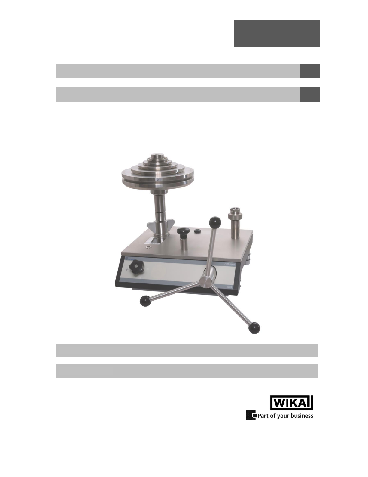
CPB5800
Pressure Balance CPB5800
CPB5800 压力天平
Page 2

Pressure Balance
CPB5800
GB
WIKA Operating Instructions Pressure Balance Version 1.1
2
GB
Operating Instructions Pressure Balance
Page 4 - 37
CN
压力天平操作说明书
第 38 - 72 页
Information
This symbol provides you with information, notes and tips.
Warning!
This symbol warns you against actions that can cause injury to people or
damage to the instrument.
Page 3

Pressure Balance
CPB5800
GB
WIKA Operating Instructions Pressure Balance Version 1.1
3
CCoonntteenntts
s
1. General .................................................................................................................................................... 5
1.1 General Instructions ............................................................................................................................... 5
1.2 Safety Instructions.................................................................................................................................. 6
2. Product Description ............................................................................................................................... 7
2.1 General Product Information ................................................................................................................. 7
2.2 Basic principle of the Pressure Balance ................................................................................................ 8
2.3 Environmental factors ............................................................................................................................ 9
2.3.1 Local fluctuations in gravity-value ...................................................................................................... 9
2.3.2 Temperature (Piston/Cylinder) ......................................................................................................... 10
2.3.3 Ambient conditions ........................................................................................................................... 10
2.3.4 How the cross-sectional area responds to pressure ........................................................................ 11
2.4 Arrangement of control elements ........................................................................................................ 11
2.4.1 Standard hydraulic base................................................................................................................... 12
2.4.2 High-pressure hydraulic base .......................................................................................................... 13
3. Commissioning and Operation ....................................................................................................... 14
3.1 Preparation .......................................................................................................................................... 14
3.1.1 Setting up the Device ....................................................................................................................... 14
3.1.2 Hydraulic pressure media used ........................................................................................................ 14
3.1.3 Installing the piston-cylinder system ................................................................................................ 15
3.1.3.1 Connection for piston-cylinder system with G3/4 B (male) thread ................................................ 16
3.1.3.2 Connection for piston-cylinder system with ConTect quick connector ......................................... 17
3.1.3 Connecting the device under test ..................................................................................................... 18
3.1.4 Venting the System .......................................................................................................................... 18
3.2 Operation ............................................................................................................................................. 19
3.2.1 Procedure for single-range piston-cylinder system 1,600 psi or 120 bar ......................................... 19
3.2.1.1 Mass loading ................................................................................................................................. 19
3.2.1.2 Approaching the pressure value ................................................................................................... 19
3.2.1.3 Pressure stable ............................................................................................................................. 19
3.2.2 Procedure for single-range piston-cylinder system 4,000 psi or 300 bar ......................................... 20
3.2.2.1 Mass load ...................................................................................................................................... 20
3.2.2.2 Approaching the pressure value ................................................................................................... 20
3.2.2.3 Pressure stable ............................................................................................................................. 20
3.2.3 Procedure for all dual-range piston-cylinder systems ...................................................................... 21
3.2.3.1 Mass load ...................................................................................................................................... 21
3.2.3.2 Approaching the pressure value ................................................................................................... 21
3.2.3.3 Pressure stable ............................................................................................................................. 21
3.2.4 Next pressure level ........................................................................................................................... 22
3.2.5 Releasing pressure .......................................................................................................................... 22
3.3 Disassembly ......................................................................................................................................... 23
4. Troubleshooting measures ................................................................................................................ 24
5. Maintenance and Care ........................................................................................................................ 25
5.1 Cleaning ............................................................................................................................................... 25
5.1.1 Piston-cylinder system ..................................................................................................................... 25
5.1.1.1 Procedure for single-range piston-cylinder system 1,600 psi or 120 bar ..................................... 26
5.1.1.2 Procedure for single-range piston-cylinder system 4,000 psi or 300 bar ..................................... 27
5.1.1.3 Procedure for all dual-range piston-cylinder systems ................................................................... 28
5.1.2 Mass set ............................................................................................................................................ 29
Page 4

Pressure Balance
CPB5800
GB
WIKA Operating Instructions Pressure Balance Version 1.1
4
5.2 Consumable Parts ............................................................................................................................... 29
5.3 Changing the hydraulic pressure medium ........................................................................................... 29
5.3.1 Removing hydraulic pressure medium ............................................................................................. 29
5.3.2 Filling in of hydraulic pressure medium ............................................................................................ 29
5.3.3 Venting of the System (after Complete Filling only) ......................................................................... 30
5.4 Recalibration ........................................................................................................................................ 30
6. Specifications ...................................................................................................................................... 31
7. Tables of masses ................................................................................................................................ 34
8. Accessories ......................................................................................................................................... 36
Page 5

Pressure Balance
CPB5800
GB
WIKA Operating Instructions Pressure Balance Version 1.1
5
1. General
1.1 General Instructions
In the following chapters detailed information on the CPB5800 pressure balance and its proper use can
be found.
Should you require further information, or should there be problems which are not dealt within detail in
the operating instructions, please contact the address below:
DH-Budenberg
A Division of WIKA Instruments Ltd.
10 Huntsman Drive, Northbank Ind. Est.
Irlam, Manchester • M44 5EG United Kingdom
Tel.: (+44) 844 406 0086
Fax: (+44) 844 406 0087
E-Mail: sales@dh-budenberg.co.uk
WIKA Alexander Wiegand SE & Co. KG
Alexander Wiegand Strasse
D-63911 Klingenberg
Tel.: (+49) 9372/132-0
Fax: (+49) 9372/132-406
E-Mail: info@wika.com
If nothing to the contrary is agreed, the pressure balance is calibrated in compliance with the currently
valid body of international regulations and can be referred directly to a national standard.
The warranty period for the pressure balance is 24 months according to the general terms of supply of
ZVEI.
The guarantee is void if the appliance is put to improper use or if the operating instructions are not
observed or if an attempt is made to open the appliance or to release attachment parts or the tubing.
We also point out that the content of these operating instructions neither forms part of an earlier or
existing agreement, assurance or legal relationship nor is meant to change these. All obligations of
WIKA Alexander Wiegand SE & Co. KG result from the respective sales contract and the general
business terms of WIKA Alexander Wiegand SE & Co. KG.
WIKA is a registered trade mark of WIKA Alexander Wiegand SE & Co. KG.
Names of companies or products mentioned in this handbook are registered trade marks of the
manufacturer.
The devices described in this manual represent the latest state of the art in terms of their design,
dimension and materials. We reserve the right to make changes to or replace materials without any
obligation to give immediate notification.
Duplication of this manual in whole or in part is prohibited.
© 2012 Copyright WIKA Alexander Wiegand SE & Co. KG. All rights reserved.
Page 6

Pressure Balance
CPB5800
GB
WIKA Operating Instructions Pressure Balance Version 1.1
6
1.2 Safety Instructions
Read these operating instructions carefully prior to operating the pressure
balance CPB5800. Its trouble-free operation and reliability cannot be guaranteed
unless the safety advice given in this manual is followed when using the device.
1. The system must only be operated by trained and authorised personnel who understand the manual
and can work according to it.
2. Trouble-free operation and reliability of the device can only be guaranteed so long as the conditions
stated under "Setting up the device" are taken into consideration.
3. The CPB5800 always has to be handled with the care required for any precision instrument (protect
from humidity, impacts and extreme temperatures). The device, the piston-cylinder-system and the
mass-set must be handled with care (don't throw, hit, etc.) and protected from contamination. By no
means apply any force to the operating elements of the CPB5800.
4. If the device is moved from a cold to a warm environment, you should therefore ensure the device
temperature has adjusted to the ambient temperature before operational use.
5. If the equipment is damaged and operates no longer safely, then it should be taken out of service
and securely marked in such a way so that it is not used until repaired.
Operator safety may be at risk if:
■ There is visible damage to the device
■ The device is not working as specified
■ The device has been stored under unsuitable conditions for an extended period of time.
If there is any doubt, please return the device to the manufacturer for repair or servicing.
6. Customers must not attempt to alter or repair the device themselves. If the instrument is opened or
attachment parts or the tubing are released, its trouble-free operation and reliability is impaired and
may endanger the operator. Please return the device to the manufacturer for any repair or
maintenance work.
7. Only original type or OEM specified seals should be used in this instrument.
8. Any procedure not included in the following instructions or outside of the manual must not be
attempted.
Page 7

Pressure Balance
CPB5800
GB
WIKA Operating Instructions Pressure Balance Version 1.1
7
2 Product Description
2.1 General Product Information
■ Application
Pressure balances are the most accurate instruments for the calibration of electronic or mechanical
pressure measuring instruments. The direct measurement of pressure, according to its definition as a
quotient of force and area, and the use of high-quality materials result in small uncertainties of
measurement and an excellent long-term stability.
For these reasons pressure balances have already been used in calibration laboratories of industry,
national institutes and research labs for many years. Due to the integrated pressure generation and the
purely mechanical measuring principle the CPB5800 is also ideally suited for on-site use as well as
service and maintenance purposes.
■ Piston-cylinder measuring system
Pressure is defined as a quotient of force and area. Correspondingly, the core of the CPB5800 is a very
precisely manufactured piston/cylinder system. The piston and cylinder are manufactured from
hardened steel and tungsten carbide, respectively, and are very well protected in a solid stainless
steel/hardened tool steel housing against impacts or contamination from outside.
As a standard the connection of the piston-cylinder system is a G3/4 female thread. The patented
ConTect quick connector is available as an option. This enables the piston-cylinder system to be
changed quickly and safely without any tools.
The CPS5800 piston-cylinder systems are available in two fundamentally different designs, depending
on measuring range.
■ Single-range piston-cylinder systems (for measuring ranges 120 bar and 300 bar or 1,600 psi and
4,000 psi respectively)
■ Dual-range piston-cylinder systems (for measuring ranges 700 bar, 1,200 bar and 1,400 bar or
10,000 psi, 16,000 psi and 20,000 psi respectively)
The accuracy is 0.015 % as a standard (optional also to 0.006 %) of reading.
The dual-range piston-cylinder system offers two measuring ranges in one housing with automatic
measuring range switching from low-pressure to high-pressure pistons. This provides the user with an
extremely flexible measuring instrument that can cover a wide measuring range with high accuracy,
with only one piston-cylinder unit and one set of masses. Additionally two test points can automatically
be achieved by the operator loading the masses only once (low pressure – high pressure area
utilisation).
The entire construction design of the piston-cylinder unit and the very precise manufacturing of the
piston and the cylinder stand for excellent operating characteristics with a long free rotation time and
low fall rates and for a very high long term stability. Therefore the recommended re-calibration interval
is 2 up to 5 years depending on the conditions of usage.
Page 8
Pressure Balance
CPB5800
GB
WIKA Operating Instructions Pressure Balance Version 1.1
8
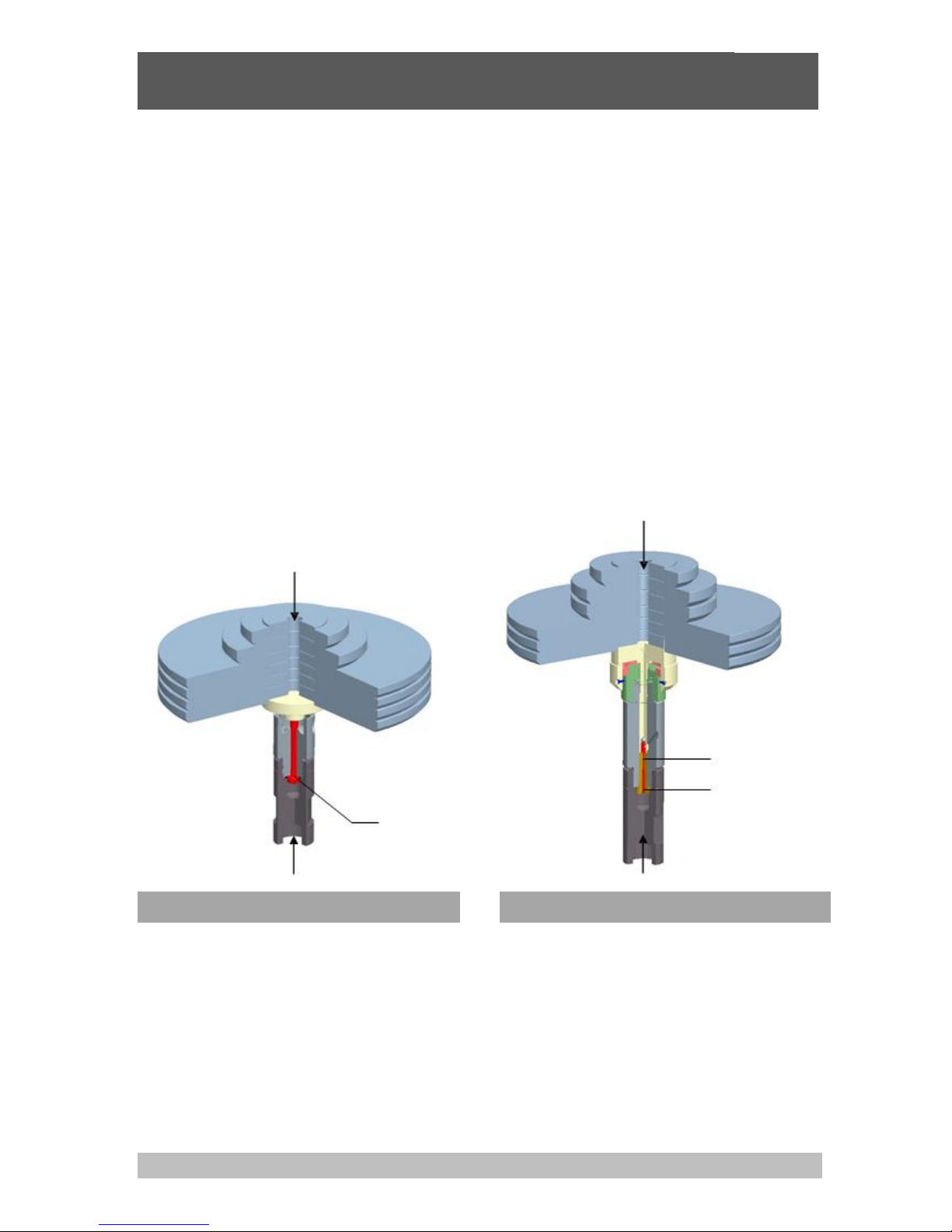
■ Functioning
Depending on the measuring range of the device under test the operator can fit the instrument base
with the corresponding system. In order to generate the individual test points, the piston-cylinder
system is loaded with masses. The weight applied is proportional to the desired pressure and provided
by using optimally graduated weights. These weights are manufactured to standard gravity (9.80665
m/s²) although they can be adjusted for customers specific location/gravity value.
The integrated priming pump and the 250 ml tank enable large test volumes to be easily filled and
pressurised. For further pressure increases and fine adjustment, a very precisely-controllable spindle
pump is fitted, which is self-contained with in the pump body when in use.
As soon as the measuring system reaches equilibrium, there is a balance of forces between the
pressure and mass load applied.
The excellent quality of the system ensures that this pressure remains stable over several minutes, so
that the pressure value for comparative measurements can be read without any problems, or also so
that more complex adjustments can be carried out on the device under test.
CPS5800 single-range piston-cylinder system
CPS5800 dual-range piston-cylinder system
Pressure p
High-pressure piston
Low-pressure piston
=High-pressure cylinder
Force F
Force F
Cross-sectional
area A
Pressure p
Page 9
Pressure Balance
CPB5800
GB
WIKA Operating Instructions Pressure Balance Version 1.1
9
2.2 Basic principle of the Pressure Balance
Their operating principle is based on the physical definition of pressure, the quotient of force and area.
Force
Pr essure
Area
The key element of the pressure balance is a precision-manufactured piston-cylinder system with a
precisely measured cross-sectional area.
To apply a pressure charge to the system, the piston is placed under a load with (calibrated) masses.
Each mass from the set of masses is identified by a nominal weight, which generates a pressure value
in the system (assuming standard reference conditions). Each mass has a number and in the
calibration certificate describing the mass value to each mass with its resultant pressure value. The
masses are chosen according to the desired pressure value.
After that, the integrated spindle pump increases the pressure until the masses are in a floating state.
2.3 Environmental factors
The piston pressure gauge is calibrated to standard reference conditions when it leaves the factory
(depending on customer specifications).
If there are significant deviations between the application conditions and the defined reference
conditions, appropriate corrections must be made.
Following are the main factors that enter into play and must be considered.
These corrections can be made automatically with the Calibrator Unit CPU6000
(see accessories point 8)!
2.3.1 Local fluctuations in gravity-value
The local force of gravity is subject to major fluctuations caused by geographical variation.
The value may differ from one place on earth to another by as much as 0.5 %. Since this value has a
direct effect on the measurement, it is essential that it be taken into consideration.
The masses can even be adjusted during manufacturing to match the location where they will be used.
Another option, especially if the device will be used at multiple locations, is to perform a calibration to
the standard gravity,
"Standard-g = 9.80665 m/s2".
Then a correction must be performed for each measurement according to the formula below:
g Application site
True pressure Nominal value
S tandard g
Example:
Local gravity set during manufacturing: 9.806650 m/s2
Locale gravity at application site: 9.811053 m/s2
Nominal pressure: 100 bar
g
Local
9.81105
True pressure: p p
Nominal
100bar 100.0449bar
g
Standard
9.80665
Without the correction, measurements would differ from the nominal applied pressure by 0.05%.
Page 10

Pressure Balance
CPB5800
GB
WIKA Operating Instructions Pressure Balance Version 1.1
10
2.3.2 Temperature (Piston-cylinder)
The effective area of the piston-cylinder system is influenced by temperature.
The effect depends on the material used and is described by the temperature coefficient (TK).
In the event of deviations from standard reference conditions (typically 20°C), the following formula
must be used to make a correction:
1
True pressure Nominal value
1tAppl tReferenceTK
Example:
Reference temperature: 20°C
Temperature during use: 23°C
TK: 0.0022%
1
True pressure100bar 99.99340bar
123 202.2
5
Without the correction, measurements would differ from the nominal applied pressure by 0.007%.
2.3.3 Ambient conditions
The effects of ambient conditions
■ air pressure
■ room temperature
■ relative humidity
should always be taken into consideration if the highest level of accuracy is required.
Fluctuations in ambient conditions change air density.
The air density affects the pressure through the buoyancy of the masses:
Air density
Weight Nominal weight 1
Weight density
The air density is typically 1.2 kg/m3
The density of the masses (non-magnetic steel) is 7900 kg/m3
A fluctuation of 5% in the relative humidity causes an additional uncertainty in the measurement of
about 0.001%.
Page 11

Pressure Balance
CPB5800
GB
WIKA Operating Instructions Pressure Balance Version 1.1
11
2.3.4 How the effective area responds to pressure
At higher pressures, the effective cross-sectional surface changes due to the pressure load.
The ratio of the cross-section and prevailing pressure is linear within an initial approximation. It is
represented by the coefficient of expansion caused by pressure distortion ().
Nominal pressure
True pressure
1
Nominal pressure
Example:
Measuring point: 1000 bar
System with distortion coefficient: 10 -7 1/bar:
1000
True pressure bar999.90bar
1110-71000
Without the correction, measurements would differ from the nominal applied pressure by 0.01%.
2.4 Arrangement of control elements
The CPB5800 instrument bases are available in 2 variants:
■ Standard hydraulic base
-
up to max 1,200 bar / 16,000 psi
-
with integrated pressure generation through priming pump and spindle pump
-
tubing made of stainless steel (1.4404), 6 x 2 mm
-
Standard pressure transmission medium: mineral oil
Optional: Sebacate oil, brake fluid, Skydrol or Fomblin oil
■ High-pressure hydraulic base
-
up to max 1,400 bar / 20,000 psi
-
with integrated pressure generation through priming pump and spindle pump
-
tubing made of stainless steel (1.4404), 6 x 2 mm
-
Pressure transmission medium: mineral oil or Sebacate oil
As a standard both instruments bases are fitted with a connection for the piston-cylinder system with
G3/4 B (male) thread.
The patented ConTect quick connector can be installed as an option allowing a quick and safe change
of the piston-cylinder system without the need for tools (not available for the hydraulic high-pressure
version!).
The connection of the test item is made without tools using a quick-connection. Via the freely-rotating
knurled nut, the test item can be oriented as required. As standard, a threaded insert with a G1/2
female thread is provided. Other threaded inserts are available to connect the most common pressure
measuring instruments.
Page 12
Pressure Balance
CPB5800
GB
WIKA Operating Instructions Pressure Balance Version 1.1
12
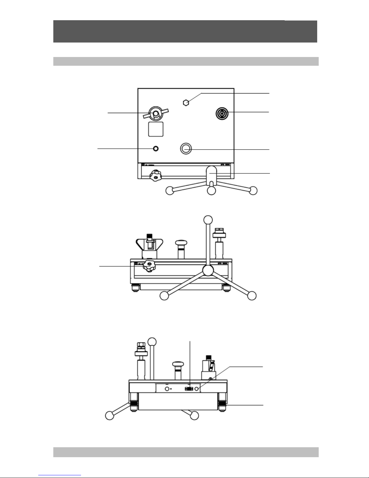
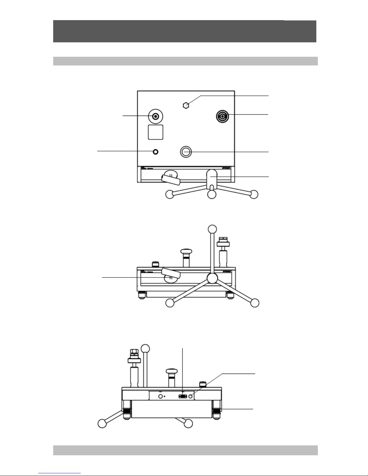
2.4.1 Standard hydraulic base
■ View from above
■ Front view
■ Rear view
Rotating foot studs
for levelling base
Interface to piston
temperature sensor
(optional and in
combination with
CPU6000 only)
Interface to float position sensor
(optional and in combination with CPU6000 only)
Outlet
valve
Priming pump
Test item
connection
Oil reservoir
sealing screw
Connector for
piston-cylinder
system
(optional ConTect
quick connection)
Level
Screwpress
Page 13
Pressure Balance
CPB5800
GB
WIKA Operating Instructions Pressure Balance Version 1.1
13
2.4.2 High-pressure hydraulic base
■ View from above
■ Front view
■ Rear view
Interface to piston
temperature sensor
(optional and in
combination with
CPU6000 only)
Rotating foot studs
for levelling base
Interface to float position sensor
(optional and in combination with CPU6000 only)
Outlet
valve
Screwpress
Priming pump
Oil reservoir sealing
screw
Connector for
piston-cylinder
system G3/4
B (male)
thread
Level
Page 14

Pressure Balance
CPB5800
GB
WIKA Operating Instructions Pressure Balance Version 1.1
14
3. Commissioning and Operation
3.1 Preparation
3.1.1 Setting up the Device
■ Set up the pressure balance on a solid surface. If it is not resting on a solid foundation or is subject
to vibrations, measurements and safety could be affected. This should be avoided.
■ If no temperature control system is present, the device should at least not be placed near a heat
element or window. This will reduce drafts and warm air flows as much as possible.
■ The spirit level should be used to level the assembly. At this time, rough levelling can be performed
without the piston-cylinder system. Using the rotating foot studs, position the device so that it is
horizontal. For uppermost accuracy, the spirit level should be put on top of the fitted piston and its
level adjusted to the horizontal.
■ Place the star handle with knobs onto the spindle pump. Ensure that the spring-loaded thrust pad
engages into the star handle bushing.
■ We recommend unscrewing the spindle pump completely when you start to record measurement
values, (turning anticlockwise) to allow enough swept displacement for measurements. The outlet
valve must be opened during this process.
■ The oil container may need to be filled, or refilled (volume 250 ml). For this purpose, the locking
screw with the oil filling symbol on top of the basement must be opened. Special oil must be used for
refilling (1 litre supplied, or available as accessory). The system must be vented before initial filling,
or after a complete oil change. For this purpose, please proceed according to section 5.3.3.
■ The protection film on the screwed drain plug of the oil container need to be removed before
operating (coverage of the ventilation hole during transportation).
3.1.2 Hydraulic pressure media used
Mineral oil based hydraulic fluid
An hydraulic mineral oil with a viscosity grade VG22 is used as standard.
Certain customers may wish to use the piston unit on other hydraulic fluids. Before
attempting this, the following should be checked:
Pressure medium is compatible with bronze, hardened tool steel, tungsten carbide and
with o-rings/composite seals used in the assembly. Special seal kits are available for
certain pressure media.
The new pressure medium being used will have inherent physical properties (density,
surface tension) that may affect the uppermost accuracy of the unit. Units that have
been manufactured for a non-standard pressure medium will have had its calibrated
mass adjusted for the fluids buoyancy and surface tension components. If the piston
unit has not been specially calibrated, the accuracy of the unit will be reduced, and this
should be taken into account.
Page 15

Pressure Balance
CPB5800
GB
WIKA Operating Instructions Pressure Balance Version 1.1
15
Skydrol 500B
The instrument base is also available for use on Skydrol 500B or any other phosphate ester based fire
resistant liquid. This base is fitted with Ethylene Polypropylene (EP) seals. The operating characteristics
of the piston-cylinder system should be tested on Skydrol. EP seals are not suitable for mineral oils.
Note that continual immersion of the instrument housing in Skydrol will cause
deterioration. Spillage should be wiped off the housing / cover immediately.
Brake fluids
The instrument base for use on non-petroleum based brake fluids should be ordered fitted with EP
seals and the operating characteristics of the piston-cylinder system should be tested on the liquid. This
liquid is known by the following names:
FMVSS No.116, DOT3 or DOT4, SAE J 1 703, BS AU 174:Part 2, IS04925.
Other fluids
The instrument base can be used on silicone based fluids, sebacate based fluids, or inert
perfluorinatedpolyethers such as Fluorolube, Fomblin, Halocarbon, which are of the viscosity as the
standard mineral oil based hydraulic fluid mentioned above and are chemically inert, being suitable for
contact with metals and with the nitrile seals which are standard on the base.
3.1.3 Installing the piston-cylinder system
■ The piston-cylinder system that is used depends on the device to be tested. You should select a
system with a comparable or higher measuring range.
■ The connection for the piston-cylinder system in the instrument base is available in 2 different
versions:
-
Connection for piston-cylinder system with G3/4 B (male) thread (see section 3.1.3.1)
-
Connection for piston-cylinder system with ConTect quick connector, not for the 1,400 bar-version
(see section 3.1.3.2)
Page 16
Pressure Balance
CPB5800
GB
WIKA Operating Instructions Pressure Balance Version 1.1
16
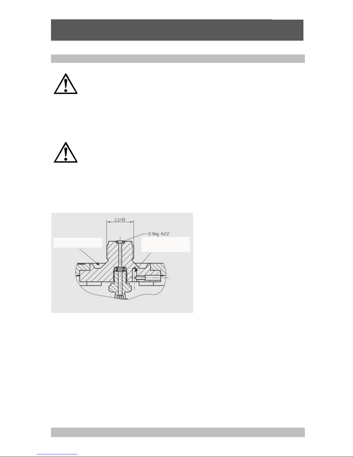
3.1.3.1 Connection for piston-cylinder system with G3/4 B (male) thread
Before removing the transit plug on the connector for the piston-cylinder system,
make sure the system is not under pressure (open the outlet valve).
■ The piston-cylinder system is connected vertically onto the thread of the piston receptacle, and
tightened by hand. Excess force is not required to achieve an effective seal. An O-ring seal is
already fitted, so no additional sealing material is required.
Ensure that the sealing surface of the piston-cylinder system is clean.
Check the o-ring in the piston stand is correctly seated and for any sign of wear.
Replace, if necessary.
■ For an exact alignment of the device, the spirit level may be removed from the base plate and placed
on the top of the fitted piston-cylinder system. This will ensure the most accurate levelling of the
piston-cylinder system.
Oil collecting tray
Temperature sensor,
optional
Page 17
Pressure Balance
CPB5800
GB
WIKA Operating Instructions Pressure Balance Version 1.1
17
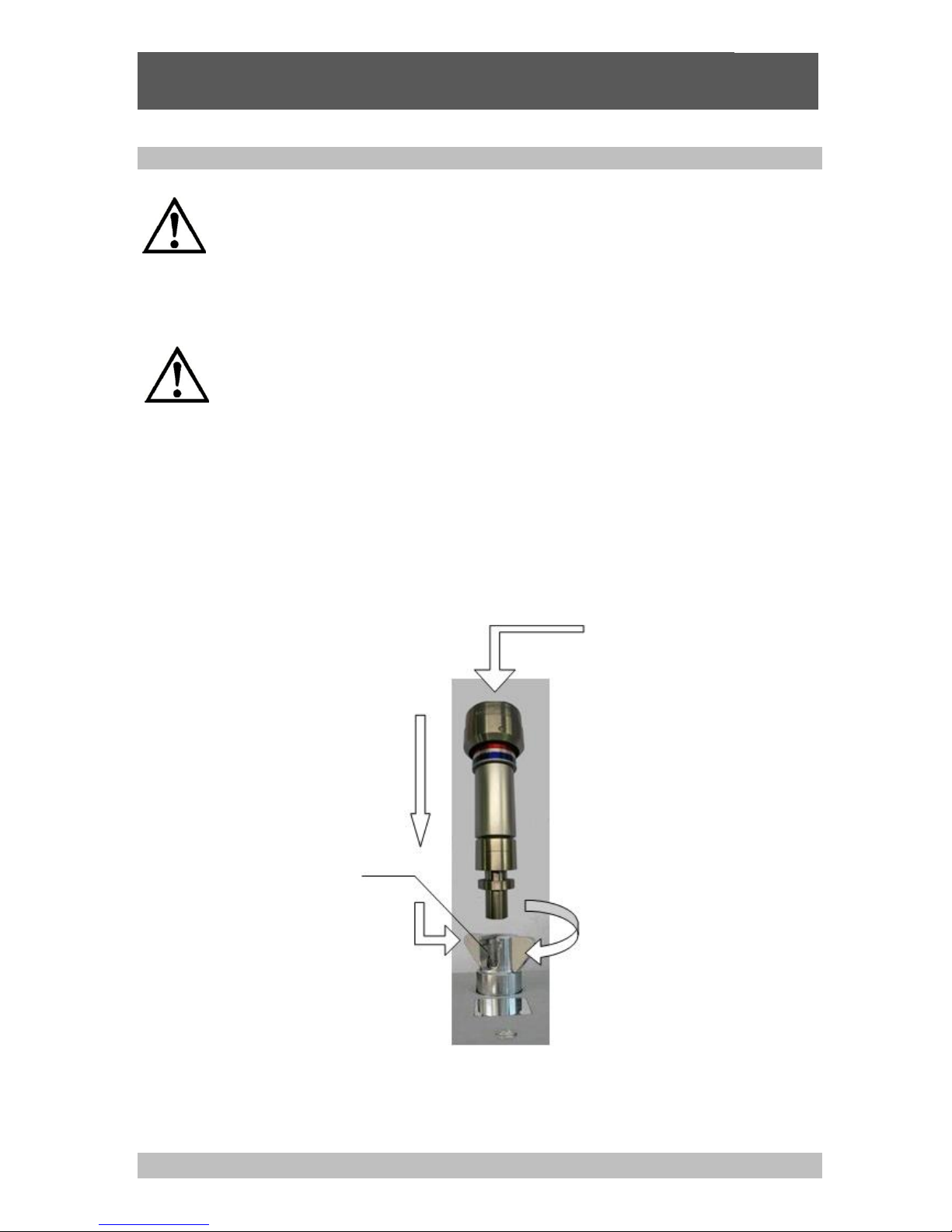
3.1.3.2 Connection for piston-cylinder system with ConTect quick connector
Before releasing the transit plug in the ConTect quick-release mechanism, make
sure the system is not under pressure (open the outlet valve).
■ Place the piston-cylinder system vertically in the quick connector.
Ensure that the sealing surface of the piston-cylinder system is clean.
Check the o-ring in the ConTect stand is correctly seated and for any sign of
Replace, if necessary.
■ Turning the butterfly screw about one and a half turn clockwise (as far as it will go) is enough to
screw the system in place with an automatic seal (finger-tight).
■ For an exact alignment of the device, the spirit level may be removed from the base plate and placed
on the top of the fitted piston-cylinder system. This will ensure the most accurate levelling of the
piston-cylinder system.
1.
4.
2.
3.
Put spirit level on
top of piston
O-ring 4 x 2.2
(see accessories section 8.)
Page 18
Pressure Balance
CPB5800
GB
WIKA Operating Instructions Pressure Balance Version 1.1
18
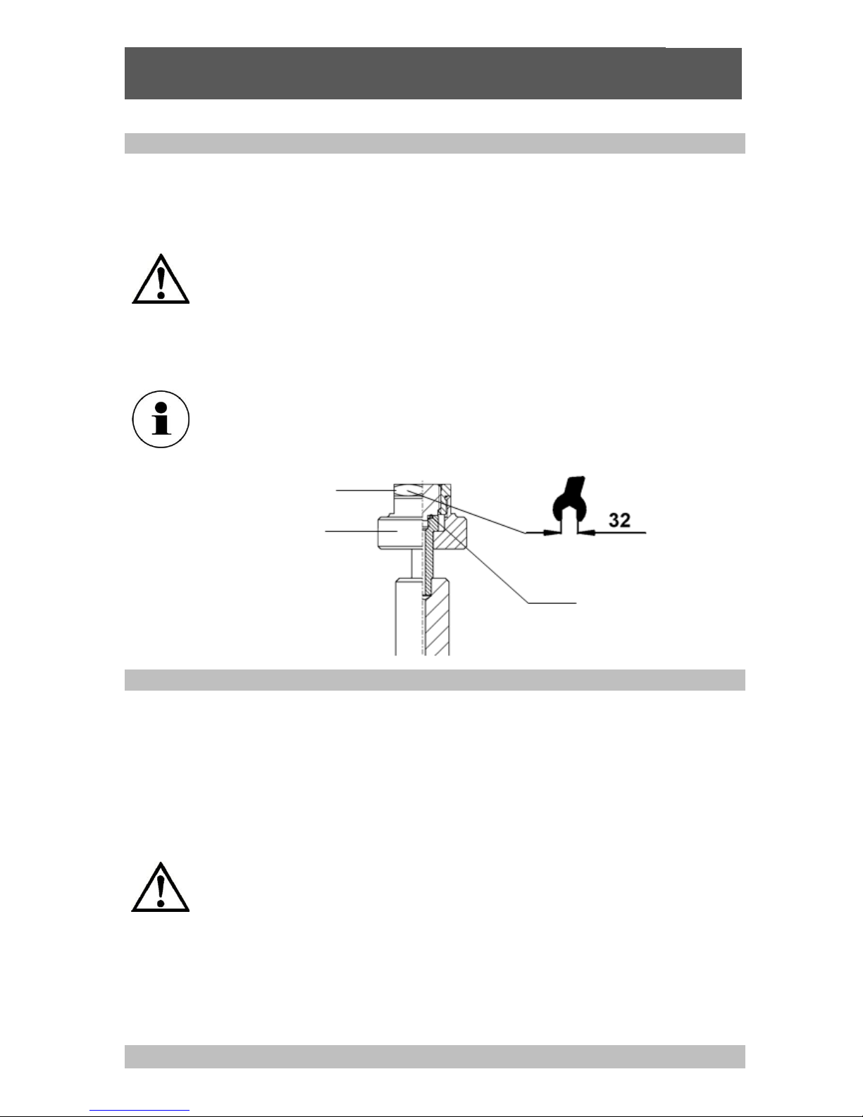
3.1.3 Connecting the device under test
■ Place the device to be calibrated/verified in the quick connector with the knurled nut. It can be freely
positioned. Hand-tightening will suffice for effective sealing.
■ To calibrate instruments with rear/back entry connections, use the 90° angle connection (see
accessories section 8).
Check the o-ring in the test stand is correctly seated and for any sign of wear.
Replace, if necessary.
Please see to it, that each instrument mounted to the pressure balance must be
clean inside.
■ The quick connector comes equipped with a G 1/2 threaded insert in the standard delivery package.
When you are calibrating devices with different connection threads, the threaded inserts
can be changed as appropriate (see accessories "Adapter Set"). For short connection
threads an additional sealing insert (order no. 2011514 resp. content of the adapter set)
can be mounted onto the existing sealing surface in the knurled nut.
3.1.4 Venting the system
After installing the piston-cylinder system and the device under test, air may be trapped in the system.
The system may be vented before beginning the calibration using the following procedure:
■ The piston-cylinder system and the device under test must be clamped, and the complete mass set
must be loaded on the piston-cylinder system.
■ Generate a pressure of approximately 50 bar using the priming pump
■ Increase the pressure with the spindle pump until just below the final value of the measuring range
of the piston-cylinder system, or of the device under test (the smaller pressure range is the decisive
factor).
Important: The piston-cylinder system must remain in its lower position for this
operation, i.e. not yet moving into equilibrium.
■ Open the outlet valve slowly, any trapped air will escape into the tank
This procedure may need to be repeated 1 to 2 times in order to remove all trapped air.
The device is now ready to use.
Threaded insert
Knurled nut
O-ring 8 x 2
(see accessories section 8.)
Page 19
Pressure Balance
CPB5800
GB
WIKA Operating Instructions Pressure Balance Version 1.1
19
3.2 Operation
3.2.1 Procedure for single-range piston-cylinder system 1,600 psi or 120 bar
3.2.1.1 Mass loading
■ Load the piston head with masses equivalent to the required pressure calibration point required.
Ensure the masses are correctly located in its respective spigot/recess.
Each mass has the following markings:
-Pressure Value
-Piston Area
-Mass set number
For high accuracy calibration, an additional marking (letter or letter/number combination)
is marked on the mass. This is to identify masses of similar nominal pressure values, and
thus obtain the actual mass value (grams) of said item.
■ This piston-cylinder unit has a basic head mass equivalent to 10 psi. If calibration is required in
another pressure unit, the first mass applied to the piston head should be the make-up mass (small
mass with ‘+PISTON’ marking).
3.2.1.2 Approaching the pressure value
■ The system must first be filled with oil and pre-compressed.
■ For this the outlet valve must be closed.
■ Operate the priming pump for several strokes. The pressure increases to a maximum of about 50
bar (depending on the volume of the connected test specimen).
■ After that, increase the pressure by turning the built-in spindle pump clockwise.
■ Just before the generated pressure reaches the actual calibration point, the masses should be
rotated by hand (approx 30-40 RPM) to ensure that the piston is in free-rotation. Care should be
applied when rotating the masses that no un-necessary transverse loads are applied to the piston.
Never rotate the piston-cylinder unit, if the piston is in the lower or upper block
position.
3.2.1.3 Pressure stable
■ Continue generating pressure until the system is in a state of equilibrium.
■ As the pressure calibration point is achieved, the piston will begin to move in an upward direction to
its ‘FLOATING’ position. The ‘FLOATING’ (free rotation) position is between 1-7mm above the
cylinder. To confirm this, the operator can press down lightly (use index finger) onto the top of the
masses applied. If the piston and masses appear to bounce (move freely up and down) the piston
unit is at pressure value of masses applied.
As there is only a small pressure change required between the piston floating/not
floating we recommend turning the pump spindle slowly and evenly clockwise.
■ The piston and thus the test pressure as well now remain stable for several minutes.
Page 20
Pressure Balance
CPB5800
GB
WIKA Operating Instructions Pressure Balance Version 1.1
20
3.2.2 Procedure for single-range piston-cylinder system 4,000 psi or 300 bar
3.2.2.1 Mass load
■ The piston head has a tapped hole in its uppermost surface. To achieve its initial start pressure
value (30 psi or 2 bar) a designated hexagonal mass must be screwed into the piston head. This
should be applied before starting any calibration.
■ Load the piston head with masses equivalent to the required pressure calibration point required.
Ensure the masses are correctly located in its respective spigot/recess.
Each mass has the following markings:
-Pressure Value
-Piston Area
-Mass set number
For high accuracy calibration, an additional marking (letter or letter/number combination)
is marked on the mass. This is to identify masses of similar nominal pressure values, and
thus obtain the actual mass value (grams) of said item.
3.2.2.2 Approaching the pressure value
■ The system must first be filled with oil and pre-compressed.
■ For this the outlet valve must be closed.
■ Operate the priming pump for several strokes. The pressure increases to a maximum of about 50
bar (depending on the volume of the connected test specimen).
■ After that, increase the pressure by turning the built-in spindle pump clockwise.
■ Just before the generated pressure reaches the actual calibration point, the masses should be
rotated by hand (approx 30-40 RPM) to ensure that the piston is in free-rotation. Care should be
applied when rotating the masses that no un-necessary transverse loads are applied to the piston.
Never rotate the piston-cylinder unit, if the piston is in the lower or upper block
position.
3.2.2.3 Pressure stable
■ Continue generating pressure until the system is in a state of equilibrium.
■ As the pressure calibration point is achieved, the piston will begin to move in an upward direction to
its ‘FLOATING’ position. The ‘FLOATING’ (free rotation) area is when the bottom edge of the
auxiliary cylinder fitted to the piston head has risen to a position within the knurled area of the stud
fitted to the piston unit. To confirm this, the operator can press down lightly (use index finger) onto
the top of the masses applied. If the piston and masses appear to bounce (move freely up and down)
the piston unit is at pressure value of masses applied.
As there is only a small pressure change required between the piston floating/not
floating we recommend turning the pump spindle slowly and evenly clockwise.
■ The piston and thus the test pressure as well now remain stable for several minutes.
Page 21
Pressure Balance
CPB5800
GB
WIKA Operating Instructions Pressure Balance Version 1.1
21
3.2.3 Procedure for all dual-range piston-cylinder systems
3.2.3.1 Mass load
■ Load the piston head with masses equivalent to the required pressure calibration point required.
Ensure the masses are correctly located in its respective spigot/recess.
Each mass has the following markings:
-Low Pressure/High Pressure Value
-Low Pressure/High Pressure Piston Area
-Mass set number
For high accuracy calibration, an additional marking (letter or letter/number combination)
is marked on the mass. This is to identify masses of similar nominal pressure values, and
thus obtain the actual mass value (grams) of said item.
■ All dual-range piston-cylinder units have a basic head mass equivalent to 10 psi (on low pressure
area). If calibration is required in another pressure unit, the first mass applied to the piston head
should be the make-up mass (small mass with ‘+PISTON’ marking)
3.2.3.2 Approaching the pressure value
■ The system must first be filled with oil and pre-compressed.
■ For this the outlet valve must be closed.
■ Operate the priming pump for several strokes. The pressure increases to a maximum of about 50
bar (depending on the volume of the connected test specimen).
■ After that, increase the pressure by turning the built-in spindle pump clockwise.
■ Just before the generated pressure reaches the actual calibration point, the masses should be
rotated by hand (approx 30-40 RPM) to ensure that the piston is in free-rotation. Care should be
applied when rotating the masses that no un-necessary transverse loads are applied to the piston.
Never rotate the piston-cylinder unit, if the piston is in the lower or upper block
position.
3.2.3.3 Pressure stable
■ Continue generating pressure until the system is in a state of equilibrium.
■ As the pressure calibration point is achieved, the piston will begin to move in an upward direction to
its ‘FLOATING’ position. On all dual range models, it has two ‘FLOATING’ (free rotation) positions to
correspond with the dual area piston unit.
One is for the low pressure area, and is indicated when a blue band with silver dashes becomes
visible.
One is for the high pressure area, and is indicated when a red band with silver dashes becomes
visible.
The bottom chamfered edge of the piston head floating anywhere within the above mentioned
bands indicates the piston unit is at pressure value of masses applied for the area it is operating on.
To confirm this, the operator can press down lightly (use index finger) onto the top of the masses
applied. If the piston and masses appear to bounce (move freely up and down) the piston unit is at
pressure value of masses applied.
Page 22
Pressure Balance
CPB5800
GB
WIKA Operating Instructions Pressure Balance Version 1.1
22
As there is only a small pressure change required between the piston floating/not
floating we recommend turning the pump spindle slowly and evenly clockwise.
■ The piston and thus the test pressure as well now remain stable for several minutes.
■ Once a pressure calibration point on the low pressure area has been achieved, the operator can
increase the system pressure until the second calibration point is achieved on the high pressure
area. This change-over of pressure areas is fully automatic, the only visible indication will be a small
amount of oil leakage appearing from an angled hole in the side of the body. This is normal, and
should not cause any undue concern.
3.2.4 Next pressure level
■ After the calibration point has been achieved, if further calibration points are required the operator
should stop the rotation of the piston unit and carefully add additional masses to the piston/mass set
before increasing pressure.
■ If required to calibrate pressure points at low values than the last calibration point, the operator
should stop the rotation of the piston unit and carefully remove the required masses, before
adjusting system pressure to required value.
3.2.5 Releasing pressure
■ Turn the spindle pump anticlockwise to release pressure in the system.
■ If the pressure is close to the next test level, make the fine adjustment with the star handle.
■ Once all calibration points have been completed, the operator should remove all pressure from the
system, and then carefully remove all masses, making unit ready for next calibration.
Attention: In this case the piston must stay in the lower position!
Caution:
The piston is lowered very quickly just before equilibrium is achieved.
Caution:
Do not remove masses completely from the piston-cylinder system under
pressure.
Page 23
Pressure Balance
CPB5800
GB
WIKA Operating Instructions Pressure Balance Version 1.1
23
3.3 Disassembly
■ After all pressure points have been achieved, open the outlet valve.
■ Now the device under test can be removed from the test stand and all masses can be removed from
the piston-cylinder system.
■ If there is another device under test with the same measurement range, the piston-cylinder system
can stay clamped in place.
■ Otherwise, we recommend removing the system and then storing it in its protective container.
Do not disconnect the test specimen or the piston-cylinder system until the
pressure in the pressure balance has been completely released.
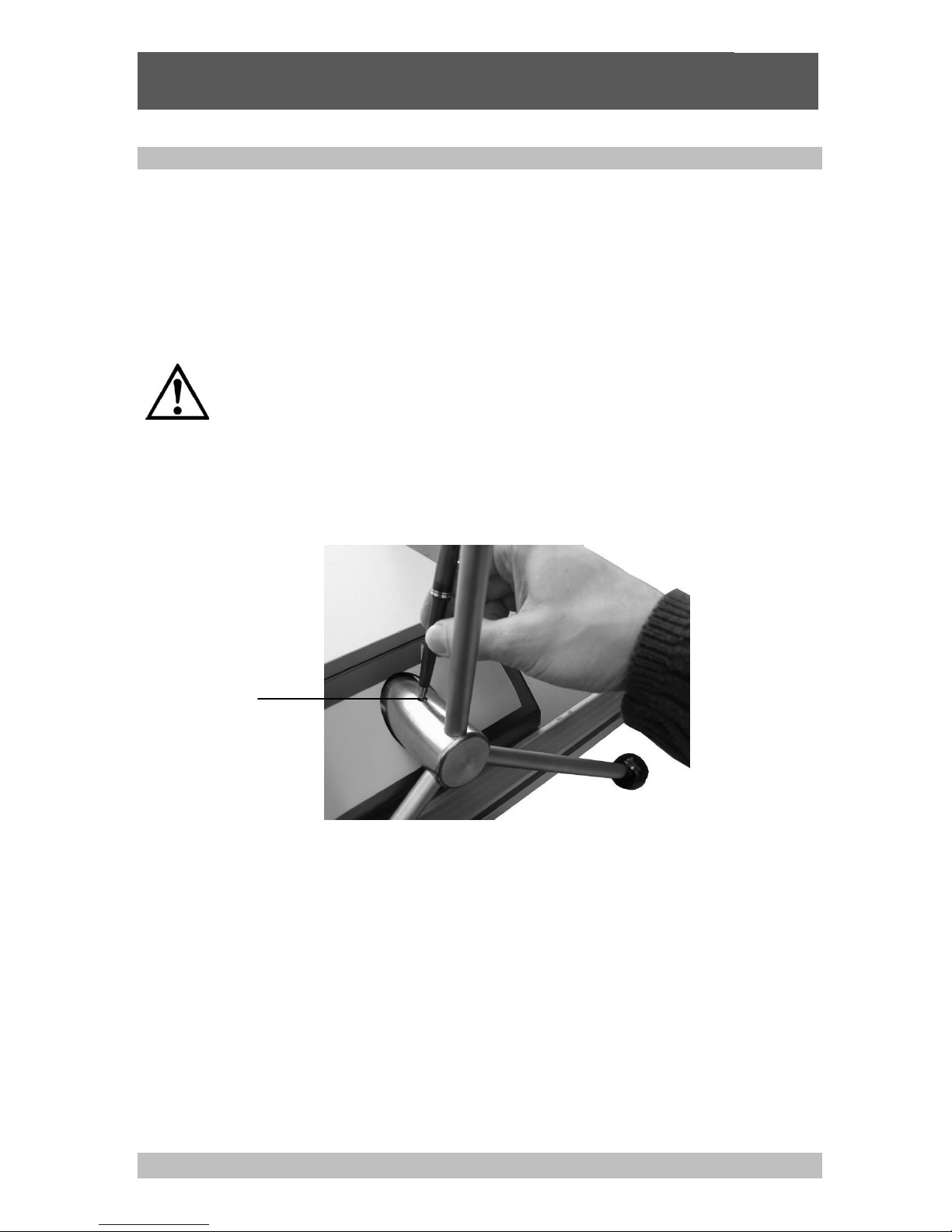
■ In order to remove the star handle from the spindle pump, the spring-loaded thrust pad must be
pressed downward with the aid of a small screwdriver, or a ball-point pen. The star handle may now
be pulled off toward the front.
Spring-loaded
thrust pad
Page 24

Pressure Balance
CPB5800
GB
WIKA Operating Instructions Pressure Balance Version 1.1
24
4. Troubleshooting measures
If faults cannot be rectified by the operator, the system must be withdrawn from
operation immediately and this information of the fault condition be supplied to the
manufacturer.
Repairs must only be carried out by the manufacturer. Unauthorized repairs and
changes on the appliance are not allowed.
Table: Fault description and measures
Type of fault
Measures
I. Unable to build up pressure / leak in the system
■ Check if there is enough fluid in the
system/reservoir.
■ Close outlet valve correctly
■ Attention: Do not over tighten outlet
valve more than finger tight, otherwise
the valve seat could be damaged.
■ Check whether the seals have been
placed in the clamp for the pistoncylinder system and test specimen and
whether they are properly positioned.
II. Unable to build up pressure, or range cannot be
reached
■ After the clamping of the piston-cylinder
system and the test specimen, air may
be trapped in the system.
■ Please note: The system should be
vented before beginning with calibration.
For this purpose, proceed according to
section 3.1.4.
■ Afterwards, build the pressure back up.
III. Slow lowering of the piston in equilibrium
■ Leak in the system, see fault I.
■ After the clamping of the piston-cylinder
system and the test specimen, air may
be trapped in the system, see point II.
■ Afterwards, build the pressure back up.
IV. Piston is not rotating or does not respond readily
■ Attention: If the piston is not turning
easily or appears to be 'sticking', do not
under any circumstances force it to turn.
Doing so could cause lasting damage
that would seriously affect measurement
accuracy.
■ The piston must be cleaned (see section
5.1.1)
Further help can be found through WIKA's Calibration Technology Department or DH-Budenberg
Customer Service.
Page 25

Pressure Balance
CPB5800
GB
WIKA Operating Instructions Pressure Balance Version 1.1
25
5. Maintenance and Care
5.1 Cleaning
5.1.1 Piston-cylinder system
To provide a method of cleaning piston units if they are to be put in storage for a length of time, are
being used on different pressure media or possibly not functioning correctly due to contamination.
Introduction
The accuracy of a dead-weight tester depends primarily on the effective area of the piston unit and on
the masses applied to the piston. The effective area of the piston unit can be affected by wear of the
unit. This is generally caused by contamination of the oil in the tester by foreign matter from instruments
being calibrated, by water, or by chemicals from instruments, or by rust or corrosion caused by
contaminants.
Tools Required
The following sections describe the necessary tools to dis-mantle the piston units for cleaning. This part
provides details of consumables that will be required to ensure the unit operational capacity is not
degraded.
Degreasing Fluid:
There are many different types of degreasing agents in commercial use. The fluid that should be used
is one that does not leave any residue on the highly polished piston or cylinder surfaces.
Cleaning Cloth:
Cloth used should not leave any particles in use. ‘Lint-Free’ cloth is the preferred material to use.
Do not use any polishing compounds to remove any marks on the piston or
cylinder. Use of such compounds, will alter its size, and thus change the calibrated
effective area of the piston unit.
We recommend you to clean the piston-cylinder systems after every use as needed. Poor sensitivity or
short free turning duration are indications the system needs to be cleaned.
To do this, remove the piston-cylinder system from the base and disassemble it as described in the
following references.
Page 26

Pressure Balance
CPB5800
GB
WIKA Operating Instructions Pressure Balance Version 1.1
26
5.1.1.1 Procedure for single-range piston-cylinder system 1,600 psi or 120 bar
TOOLS Required:
30mm A/F wrench, o-ring removal tool, Ø10 Tommy bar,
1.5 mm A/F Allen key, Lint free cleaning cloth
Stand piston unit on table, and using the Ø10 Tommy bar and 30mm A/F
wrench unscrew anti-clockwise as shown. Remove o-ring in piston adaptor
Using 1.5 mm A/F Allen key remove the piston stop collar. Once removed, lift
the cylinder in a vertical direction until it is no longer engaged to the piston.
Place all parts in a clean and stable location
Degrease all metal components. The piston and cylinder (see picture) should
be wiped with lint-free cloth, and examined for significant scratches. For
cleaning cylinder, cut a 500mm long tapered length of lint-free as shown
Stand piston in vertical orientation and apply pressure medium to piston. Slide
cylinder onto piston in the vertical orientation.
DO NOT FORCE – this should be a precision sliding fit.
Re-fit the piston stop collar using 1.5 mm A/F Allen key. Ensure the fixing
screw is correctly located in the recess in the piston. Failure to achieve this
may result in the piston coming out of its cylinder when under pressure.
Fit clean/compatible o-ring to piston adaptor, and using the Ø10 Tommy bar
and 30mm A/F wrench screw piston adaptor onto cylinder clockwise as shown.
Never touch the cleaned piston with your bare hands. The natural dermal-grease
can cause a contamination of the piston-cylinder system.
Never use excess force to fit the piston to the cylinder, permanent damage can
occur.
The system is now ready to use again.
Cleaning cloth for
cylinder. Large end
must be wide enough
to be a tight when
pulled through
cylinder
Page 27

Pressure Balance
CPB5800
GB
WIKA Operating Instructions Pressure Balance Version 1.1
27
5.1.1.2 Procedure for single-range piston-cylinder system 4,000 psi or 300 bar
TOOLS Required:
O-ring removal tool, Lint free cleaning cloth
Stand piston assembly on table, and unscrew anti-clockwise as shown.
Remove o-ring in piston adaptor
Withdraw the piston from its cylinder in a vertical direction. Once piston is out
of the cylinder, withdraw the cylinder from the auxiliary cylinder.
Degrease all metal components.
The piston and cylinder (see picture) should be wiped with lint-free cloth, and
examined for longitudinal scratches. For cleaning cylinder, cut a 500mm long
tapered length of lint-free as shown
Apply pressure medium to cylinder outside diameter. Fit cylinder into clamping
nut, and the fit cylinder into auxiliary cylinder/head as shown.
DO NOT FORCE – this should be a precision sliding fit.
Stand cylinder assembly on table and fit piston to cylinder as shown.
DO NOT FORCE – this should be a precision sliding fit.
Fit clean/compatible o-ring to piston adaptor, and screw piston adaptor onto
cylinder clockwise as shown.
Never touch the cleaned piston with your bare hands. The natural dermal-grease
can cause a contamination of the piston-cylinder system.
Never use excess force to fit the piston to the cylinder, permanent damage can
occur.
The system is now ready to use again.
Cleaning cloth for
cylinder. Large end
must be wide enough
to be a tight when
pulled through
cylinder
Page 28

Pressure Balance
CPB5800
GB
WIKA Operating Instructions Pressure Balance Version 1.1
28
5.1.1.3 Procedure for all dual-range piston-cylinder systems
TOOLS Required:
30mm A/F wrench, o-ring removal tool, Ø4.8 Tommy bar, rubber strap
wrench, Lint free cleaning cloth
Grasp coloured indicating band cap and fit Ø4.8 Tommy bar into angled hole
of low pressure cylinder and unscrew anti-clockwise 1 full rotation as shown.
If you cannot separate the 2 parts, a rubber strap wrench should be employed
Stand piston assembly on table, and unscrew anti-clockwise as shown. Slide
the main diameter in a vertical direction until it becomes clear of high
pressure piston.
Fit Ø4.8 Tommy bar into angled hole of low pressure cylinder and 30mm A/F
wrench to pressure adaptor and unscrew anti-clockwise.
Remove the LP piston.
Remove o-ring in piston adaptor. Degrease all metal components - do not
degrease coloured band cap
The HP and LP piston, auxiliary and cylinder (see picture) should be wiped
with lint-free cloth, and examined for longitudinal scratches. For cleaning
cylinder, cut a 500mm long tapered length of lint-free as shown
Apply pressure medium to auxiliary. Insert piston head/auxiliary subassembly into low pressure cylinder
DO NOT FORCE – this should be a precision sliding fit.
Apply pressure medium to LP piston (inside and outside). Insert LP piston
into low pressure cylinder
DO NOT FORCE – this should be a precision sliding fit.
Fit clean/compatible o-ring to piston adaptor, and screw piston adaptor onto
cylinder clockwise as shown.
Never touch the cleaned piston with your bare hands. The natural dermal-grease
can cause a contamination of the piston-cylinder system.
Never use excess force to fit the piston to the cylinder, permanent damage can
occur.
The system is now ready to use again.
Cleaning cloth for
cylinder. Large
end must be wide
enough to be a
tight when pulled
through cylinders
HP piston
LP piston
auxiliary
Page 29

Pressure Balance
CPB5800
GB
WIKA Operating Instructions Pressure Balance Version 1.1
29
5.1.2. Mass set
■ The masses should be handled with gloves.
■ If fingerprints or other impurities are found on the masses in spite of this precaution, they can be
removed with a suitable degreasing fluid.
5.2 Consumable Parts
O-rings in the piston-cylinder retaining system and test stand are subjected to wear. Both O-rings must
be checked if they are correctly seated and for any wear before any calibrating is performed. If
necessary, the O-rings must be replaced in regular intervals, or whenever necessary (see Accessories,
section 8).
Important: Use original seals only. Seals having deviant measurements, or
materials, or material grades, may cause damage to the device and test specimen,
and pose a danger for the operator.
5.3 Changing the hydraulic pressure medium
The hydraulic oil should be changed whenever visible contamination is present.
5.3.1. Removing hydraulic pressure medium
■ Open the locking screw with the oil filling symbol on top of the base. Depress priming pump and
wind spindle pump fully clockwise.
■ Siphon the oil out of the tank, for example, by using a suitable syringe
■ Small amounts of oil residue additionally may be siphoned off the connections with the receptacle for
the piston-cylinder system and test specimen connection opened and with the outlet valve closed, by
means of slowly turning in of the spindle pump
■ Minute amounts of oil residue may remain in the piping
In case of severe contamination of the hydraulic oil, the complete cleaning of the piping
and of all media-contacted individual components of the basement in a dismantled state
may be advisable. This procedure may be performed by the manufacturer only.
Waste oil must be disposed of according to legal requirements.
5.3.2. Filling in of hydraulic pressure medium
■ Turn in the spindle pump clockwise until it reaches the initial stop
■ Close the outlet valve
■ Open the locking screw with the oil filling symbol on top of the instrument base
■ Fill with required pressure medium (1 litre supplied, or available as accessory) via the tank opening,
until the fill level reaches the thread of the tank opening (approximately 250ml). The fill level must
always be observed.
■ Rotate the spindle pump counter-clockwise until it reaches the rear stop. The pressure medium is
automatically transferred out of the tank into the system.
■ Close the tank opening with the locking screw
Page 30

Pressure Balance
CPB5800
GB
WIKA Operating Instructions Pressure Balance Version 1.1
30
5.3.3. Venting of the system (after complete filling only)
After initial filling, or after a complete pressure medium change, air may be trapped in the system. The
system should be vented using the following procedure:
■ The piston-cylinder system and test specimen connections must be open
■ Close the outlet valve
■ Twist out the spindle pump counter-clockwise until it reaches the rear stop.
■ Carefully operate using the priming pump, while continuously observing the filling medium in the
open piston-cylinder system and test specimen connections. At this point, trapped air escapes
toward the exterior by means of the formation of bubbles. The priming pump must be operated until
air bubbles no longer appear.
■ Any oil escaping in the open piston-cylinder system and test specimen connections should be wiped
clean before commencing any other operation.
5.4. Recalibration
The recommended interval between recalibrations is 2 up to 5 years depending on the conditions of
usage.
This interval assumes the system and masses are handled carefully.
If the system is used in harsh/industrial environments, we recommend shortening the interval to about
three years.
The pressure balance should be immediately maintained and recalibrated, if:
■ the operating characteristics deteriorate (duration of free rotation, sink rate, sensitivity)
■ the masses are damaged or corroded
For recalibration or if you have questions about the optimal recalibration cycle, the DKD or UKAS lab
would be happy to assist you:
DH-Budenberg
A Division of WIKA Instruments Ltd.
10 Huntsman Drive, Northbank Ind. Est.
Irlam, Manchester • M44 5EG United Kingdom
Tel.: (+44) 844 406 0086
Fax: (+44) 844 406 0087
E-Mail: sales@dh-budenberg.co.uk
WIKA Alexander Wiegand SE & Co. KG
Alexander Wiegand Strasse
D-63911 Klingenberg
Tel.: (+49) 9372/132-0
Fax: (+49) 9372/132-406
E-Mail: info@wika.com
Page 31

Pressure Balance
CPB5800
GB
WIKA Operating Instructions Pressure Balance Version 1.1
31
6. Specifications
Model CPS5800 piston-cylinder systems
Version
Single-piston measuring
ranges
Dual-piston measuring ranges
Measuring range 1)
bar,
kg/cm²
1 … 120
2 … 300
1 … 60 /
10 … 700
1 … 60 /
20 … 1,200
1 ... 60 /
20 ... 1,400
Required masses
kg
49.7
49.6
57.4
49.2
57.4
Smallest step 2)
(Standard mass tests)
bar, kg/cm²
0.5
2.5
0.5 / 5.0
0.5 / 10
0.5 / 10
Smallest step 3)
(fine increment masses)
bar, kg/cm²
0.02
0.05
0.01 / 0.1
0.01 / 0.2
0.01 / 0.2
Nominal cross-sectional
area of the piston
cm²
0.4032
0.1613
0.8065 / 0.0807
0.8065 / 0.0403
0.8065 / 0.0403
Measuring range 1)
psi, lb/in²
10 … 1,600
30 … 4,000
10 … 800 /
100 … 10,000
10 … 800 /
200 … 16,000
10 ... 800 /
200 ... 20,000
Required masses
kg
45.5
45.3
56.4
45
56.4
Smallest step 2)
(Standard mass tests)
psi, lb/in²
5
20
5 / 50
5 / 100
5 / 100
Smallest step 3)
(fine increment masses)
psi, lb/in²
0.2
0.5
0.1 / 1
0.1 / 2
0.1 / 2
Nominal cross-sectional
area of the piston
cm²
0.4032
0.1613
0.8065 / 0.0807
0.8065 / 0.0403
0.8065 / 0.0403
Measuring range 1)
kPa
100 …
12,000
200 …
30,000
100 … 6,000 /
1,000 … 70,000
100 … 6,000 /
2,000 …
120,000
100 ... 6,000 /
2,000 ...
140,000
Required masses
kg
49.7
49.6
57.4
49.2
57.4
Smallest step 2)
(Standard mass tests)
kPa
50
250
50 / 500
50 / 1,000
50 / 1,000
Smallest step 3)
(fine increment masses)
kPa 2 5
1 / 10
1 / 20
1 / 20
Nominal cross-sectional
area of the piston
cm²
0.4032
0.1613
0.8065 / 0.0807
0.8065 / 0.0403
0.8065 / 0.0403
Accuracies
Standard
4) 5) 6)
% of
reading
0.015
0.015
0.015
0.015
0.025
Premium
4) 5) 7)
% of
reading
0.007
0.006
0.006
0.007
0.007
Pressure transmission medium
Standard
Hydraulic fluid based on VG22 mineral oil
Optional
Sebacate oil
Brake fluid
Skydrol
Fomblin oil
Sebacate oil
Brake fluid
Skydrol
Fomblin oil
Sebacate oil
Brake fluid
Skydrol
Fomblin oil
Sebacate oil
Brake fluid
Skydrol
Fomblin oil
Sebacate oil
Material
Piston
Steel
Steel
Tungsten
carbide / steel
Tungsten carbide
/ steel
Tungsten
carbide / steel
Cylinder
Bronze
Steel
Steel / tungsten
carbide
Steel / tungsten
carbide
Steel / tungsten
carbide
Mass set
Stainless steel, non-magnetic
Weight
Piston-cylinder system
kg 1 0.8 2 2
2
Storage case for piston
cylinder system
kg
3.1
BAR standard mass sets
(in 2 wooden cases)
kg
61.3
61.2
69
60.8
69
PSI standard mass sets
(in 2 wooden cases)
kg
57.1
56.9
68
56.6
68
BAR fine increment
masses
kg
0.33
0.5
0.5
0.5
0.5
PSI fine increment masses
kg
0.23
0.34
0.34
0.34
0.34
Dimensions
Carrying case for
standard mass sets
400 x 310 x 310 mm (W x H x D)
Page 32

Pressure Balance
CPB5800
GB
WIKA Operating Instructions Pressure Balance Version 1.1
32
Storage case for pistoncylinder systems (optional)
300 x 265 x 205 mm (W x H x D)
1) Theoretical starting value; corresponds to the pressure value generated by the piston or the piston and its make-up weights (by their own weight). To optimise the
operating characteristics more masses should be loaded.
2) The smallest pressure change value that can be achieved based on the standard mass set. To reduce this, a set of trim masses is also available.
3) The smallest pressure change value that can be achieved based on the optional fine increment masses. For further reductions, an accessory of class M1 or F1 set
of trim masses is available.
4) The accuracy from 10 % of the measuring range is based on the measured value. In the lower range, the accuracy is 0.03 % of reading for the single-range pistoncylinder systems and 0.025 % of reading for dual-range piston-cylinder systems.
5) Measurement uncertainty assuming reference conditions (ambient temperature 20 °C, air pressure 1013 mbar, relative humidity 40 %). For operation without a
CalibratorUnit, corrections must be made if required.
6) Not available with UKAS area and mass calibration
7) Requires UKAS area and mass calibration
Model CPB5800 base
Base version
Hydraulic standard
up to a max. 1,200 bar / 16,000 psi; with internal pressure generation
Hydraulic high-pressure
up to a max. 1,400 bar / 20,000 psi; with internal pressure generation
Pressure transmission medium
Standard
Hydraulic fluid based on VG22 mineral oil
Optional
Sebacate oil, brake fluid, Skydrol or Fomblin oil (dependant upon measuring
range)
Oil reservoir
250 cm3
Connections
Connection for piston-cylinder system
G ¾ male / optional: ConTect quick-release connector (not for 1,400 bar version)
Test tem connecter
G ½ B female quick connector as standard, freely rotating, changeable (for other
threaded inserts, see accessories)
Material
Piping in instrument base
1.4404 stainless steel, 6 x 2 mm
Weight
Standard hydraulic base
18.0 kg / 19.0 kg (incl. optional ConTect quick-release connector)
Hydraulic high-pressure base
18.0 kg
Storage case for the base
8.5 kg
Permissible ambient conditions
Operating temperature
18... 28 °C
Dimensions
Base
400 x 375 x 265 mm (W x D x H), for details, see technical drawings
CE conformity and certificates
CE conformity
Pressure equipment directive
97/23/EC (Module A)
Certificate
Calibration
Calibration certificate
Option: UKAS calibration certificate
1) 2)
1) For standard accuracy UKAS calibration certificate only available as pressure calibration.
2) Premium accuracy requires UKAS area and mass calibration
Approvals and certificates, see website
Page 33

Pressure Balance
CPB5800
GB
WIKA Operating Instructions Pressure Balance Version 1.1
33
Scope of delivery
Base with dust protection cover
Priming pump
Spindle pump for pressure generation and
fine adjustment
Piston connection with G3/4 B (male)
thread
Quick connector for test items with G ½
(female) threaded insert, changeable
Piston-cylinder system
Standard mass set in carrying case
Set of masses manufactured to standard
gravity (9.80665 m/s²)
VG22 mineral oil (1.0 litre)
Operating instructions in German and
English language
Factory calibration certificate
Options
Other pressure transmission media
Piston connection with ConTect quick-
release connector or M30x2 female thread
System with increased accuracy to
0.006 %
Other pressure units
Set of masses manufactured to local
gravity
Fine increment masses
Storage case for the base and the piston-
cylinder system
UKAS calibration certificate
Combination with CPS/CPM5000 series
units possible (please contact WIKA sales
team for further information)
Dimensions
Detailed section view
1,400 bar high-pressure version
-with high-pressure shut-off valve
-no ConTect quick-release
connector possible
Dimensions are identical
Page 34

Pressure Balance
CPB5800
GB
WIKA Operating Instructions Pressure Balance Version 1.1
34
7. Tables of masses
The following tables show the amount of masses per measuring range within a mass set with their
resulting nominal pressures.
Should you not operate the device under reference conditions (ambient temperature 20°C, air pressure
1013 mbar, relative humidity 40%), the corrections according to section 2.3 must be considered.
Measuring rang
[bar] or [kg/cm2]
Single-piston measuring
ranges
Dual-piston measuring ranges
1 … 120
2 … 300
1 ... 700
1 ... 1,200
1 ... 1,400
1 ... 60
10 ... 700
1 ... 60
20 ... 1,200
1 ... 60
20 ... 1,400
Quantity
Nominal
pressure
per piece
Quantity
Nominal
pressure
per piece
Quantity
Nominal
pressure
per piece
Nominal
pressure
per piece
Quantity
Nominal
pressure
per piece
Nominal
pressure
per piece
Quantity
Nominal
pressure
per piece
Nominal
pressure
per piece
[bar]
[kg/cm2]
[bar]
[kg/cm2]
[bar]
[kg/cm2]
[bar]
[kg/cm2]
[bar]
[kg/cm2]
[bar]
[kg/cm2]
[bar]
[kg/cm2]
[bar]
[kg/cm2]
Piston and make-up
weight
1 1 1 2 1 1 10 1 1
20 1 1
20
Standard mass set
4
20 4 50 5 10
100 4 10
200 5 10
200 1
18 1 45 1 9
90 1 9
180 1 9
180 1
10 1 25 1 5
50 1 5
100 1 5
100 2 4 2
10 2 2
20 2 2
40 2 2
40
1 2 1 5 1 1
10 1 1
20 1 1
20
2 1 1 3 1 0.5 2 1
0.5
10 1 0.5
10
1 0.5 1 2.5
Fine increment weights
(optional)
1
0.4 2 1 2 0.2 2 2
0.2 4 2
0.2 4 1
0.2 1 0.5 1 0.1 1 1
0.1 2 1
0.1
2
1 0.1 1 0.25 1 0.05
0.5 1 0.05 1 1
0.05 1 2 0.04 2 0.1 2 0.02
0.2 2 0.02
0.4 2 0.02
0.4 1
0.02 1 0.05 1 0.01
0.1 1 0.01
0.2 1 0.01
0.2
Measuring rang
[psi] or [lb/in2]
Single-piston measuring
ranges
Dual-piston measuring ranges
10 … 16,000
30 … 4,000
10 ... 10,000
10 ... 16,000
100 ... 20,000
10 ... 800
100 ...
10 ... 800
200 ...
10 ... 800
200 ...
10,000
16,000
20,000
Quantity
Nominal
pressure
per piece
Quantity
Nominal
pressure
per piece
Quantity
Nominal
pressure
per piece
Nominal
pressure
per piece
Quantity
Nominal
pressure
per piece
Nominal
pressure
per piece
Quantity
Nominal
pressure
per piece
Nominal
pressure
per piece
[psi]
[lb/in2]
[psi]
[lb/in2]
[psi]
[lb/in2]
[psi]
[lb/in2]
[psi]
[lb/in2]
[psi]
[lb/in2]
[psi]
[lb/in2]
[psi]
[lb/in2]
Piston 1 10 1
10
100 1 10
200 1 10
200
Piston and make-up
weight
1
30
Standard mass set
6
200 6 500 8 100
1,000 6 100
2,000 8 100
2,000 1
180 1 450 1 90
900 1 90
1,800 1 90
1,800 1
100 1 250 1 50
500 1 50
1,000 1 50
1,000
2 40 2 100 2 20
200 2 20
400 2 20
400 1
20 1 50 1 10
100 1 10
200 1 10
200 2
10 1 25 1 5
50 1 5
100 1 5
100 1 5 1
20
Fine increment weights
(optional)
1 4 2
10 2 2
20 2 2
40 2 2
40 1 2 1 5 1 1
10 1 1
20 1 1
20
1 1 1 2.5 1 0.5 5 1
0.5
10 1 0.5
10
2 0.4 2 1 2 0.2 2 2
0.2 4 2
0.2 4 1 0.2 1 0.5 1 0.1 1 1
0.1 2 1
0.1
2
Page 35

Pressure Balance
CPB5800
GB
WIKA Operating Instructions Pressure Balance Version 1.1
35
Measuring rang
[kPa]
Single-piston measuring
ranges
Dual-piston measuring ranges
100 … 12,000
200 … 30,000
100 ... 70,000
100 ... 120,000
100 ... 140,000
100 ...
1.000 ...
100 ...
2,000 100 ...
2,000 ... 6,000
70,000
6,000
120,000
6,000
140,000
Quantity
Nominal
pressure
per piece
Quantity
Nominal
pressure
per piece
Quantity
Nominal
pressure
per piece
Nominal
pressure
per piece
Quantity
Nominal
pressure
per piece
Nominal
pressure
per piece
Quantity
Nominal
pressure
per piece
Nominal
pressure
per piece
[kPa] [kPa] [kPa]
[kPa] [kPa]
[kPa] [kPa]
[kPa]
Piston and make-up
weight
1
100 1 200 1 100
1,000 1 100
2,000 1 100
2,000
Standard mass set
4
2,000 4 5,000 5 1,000
10.000 4 1,000
20.000 5 1,000
20.000
1 1,800 1 4,500 1 900
9,000 1 900
18,000 1 900
18,000 1
1,000
1
2,500 1 500
5,000 1 500
10,000 1 500
10,000 2
400 2 1,000 2 200
2,000 2 200
4,000 2 200
4,000
1 200 1 500 1 100
1,000 1 100
2,000 1 100
2,000 2
100 1 300 1 50
500 1 50
1,000 1 50
1,000 1
50 1 250
Fine increment weights
(optional)
1
40 2 100 2 20
200 2 20
400 2 20
400 1 20 1 50 1 10
100 1 10
200 1 10
200
1 10 1 25 1 5
50 1 5
100 1 5
100 2 4 2
10 2 2
20 2 2
40 2 2
40 1 2 1 5 1 1 10 1 1
20 1 1
20
Page 36

Pressure Balance
CPB5800
GB
WIKA Operating Instructions Pressure Balance Version 1.1
36
8. Accessories
CalibratorUnit model CPU6000
The models of the CPU6000 series are compact
tools for use with a pressure balance. In particular
when highly-accurate measuring values, with
measurement uncertainties of less than 0.025 %, are
required, complicated mathematical calculations and
corrections are necessary. With the CPU6000 in
combination with the CPB-CAL (iPad® app) and/or
WIKA-CAL (PC software) all critical ambient
parameters can be registered and automatically
corrected.
The CPU6000 series is made up of three
instruments:
Weather station, model CPU6000-W
The CPU6000-W provides measured values such as
atmospheric air pressure, relative humidity and the
ambient temperature of the laboratory environment.
Pressure balance sensor box, model CPU6000-S
The CPU6000-S measures the piston temperature
and displays the floating position of the masses.
Digital multimeter, model CPU6000-M
The CPU6000-M fulfills the function of a digital
multimeter and power supply unit when electronic
pressure transmitters must be calibrated.
CPB-CAL iPad® app
The iPad® application calculates the mass loads for
pressure balances or the reference pressure while
taking the measured parameters from the CPU6000
into account. The conversion can be carried out in all
common pressure units. As an additional parameter,
the local gravity can be specified for locationindependent measurements.
WIKA-CAL PC software – Weight calculator
With the demo version of the WIKA-CAL software
and a CPB series pressure balance, the masses to
be applied and the corresponding reference pressure
can be determined. The pressure balance data can
be entered into the database manually or imported
automatically via an online available XML file. All
ambient parameters and piston temperature can be
entered manually into WIKA-CAL or can be
measured automatically with the CPU6000 series, so
that the highest accuracy can be achieved. WIKACAL demo version can be downloaded free of
charge from the WIKA website.
Further specifications on the CPU6000 series can be
found in data sheet CT 35.02.
For details of the WIKA-CAL calibration software see
data sheet CT 95.10.
CPU6000 series and iPad®-App CPB-CAL
Model CPU6000-W, CPU6000-S, CPB5800
and PC with WIKA-CAL software
WIKA-CAL PC software – Weight calculator
Page 37

Pressure Balance
CPB5800
GB
WIKA Operating Instructions Pressure Balance Version 1.1
37
Further accessories
Description / Features
Order no.
Set of trim masses (1 mg up to 50 g), class F1
7093874
Set of trim masses (1 mg up to 50 g), class M1
14025325
Set of adapters for quick connector in case with G 1/4, G 3/8, 1/2 NPT, 1/4 NPT and M20 x
1.5 threaded inserts for insertion in the knurled nut on the test item connector
2036941
Set of "NPT" adapters for quick connector in case with 1/8 NPT, 1/4 NPT, 3/8 NPT and 1/
2
NPT threaded inserts for insertionin the knurled nut on the test item connector
12563626
90° angle connection, for test items with back mounting connection
1564838
Separator (without diaphragm), max. 1,000 bar
1565389
Separator (to separate two liquid media by a diaphragm), max. 700 bar
14031253
Separator (to separate two liquid media by a diaphragm), max. 1,200 bar
14031254
O-ring set consisting of 5 pcs. 8 x 2 and 5 pcs. 4 x 2.2
12328562
Operating fluid for CPB series up to a max. 4,000 bar, 1 litre
2099882
Adapter for mounting model CPS5800 hydraulic piston-cylinder systems into a ConTect
system mechanism
14031252
Test item connection, G 3/4 female to G 1/2 female, rotating, operation as a comparison
test pump is possible
14031251
Special test-item adapter with quick connect, for the matching to the ConTect system
mechanism, operation as a comparison test pump is possible
2152634
Electrical piston drive unit for 700 bar, 1,200 bar and 1,400 bar measuring ranges (AC
230 V/50 Hz)
14031260
Page 38

压力天平
CPB5800
CN
威卡 (WIKA) 压力天平操作说明书 1.1 版
38
CN
提示
提供信息、备注和实用窍门。
警告!
表示潜在危险情况,可能导致人身伤害或设备损坏。
Page 39

压力天平
CPB5800
CN
威卡 (WIKA) 压力天平操作说明书 1.1 版
39
目
目
录
录
1.概述 ......................................................................................................................................................... 41
1.1 简介 ...................................................................................................................................................... 41
1.2 安全说明 ............................................................................................................................................... 42
2.产品说明 .................................................................................................................................................. 43
2.1 一般产品信息 ....................................................................................................................................... 43
2.2 压力天平的基本原理 ............................................................................................................................ 44
2.3 环境因素 .............................................................................................................................................. 45
2.3.1 重力值的局部波动 ............................................................................................................................. 45
2.3.2 温度(活塞/缸体) ............................................................................................................................ 46
2.3.3 环境条件 ........................................................................................................................................... 46
2.3.4 截面面积如何对压力做出反应........................................................................................................... 47
2.4 控制元件的配置.................................................................................................................................... 47
2.4.1 标准液压底座 .................................................................................................................................... 48
2.4.2 高压液压底座 .................................................................................................................................... 49
3.调试和操作 .............................................................................................................................................. 50
3.1 准备 ...................................................................................................................................................... 50
3.1.1 设置设备 ........................................................................................................................................... 50
3.1.2 使用的液压介质 ................................................................................................................................ 50
3.1.3 安装活塞缸系统 ................................................................................................................................ 51
3.1.3.1 使用 G3/4 B 外螺纹连接活塞缸系统 .............................................................................................. 52
3.1.3.2 使用 ConTect 快速连接器连接活塞缸系统 .................................................................................... 53
3.1.4 连接受测设备 .................................................................................................................................... 54
3.1.5 排空系统 ........................................................................................................................................... 54
3.2 操作 ...................................................................................................................................................... 55
3.2.1 1,600 psi 或 120 bar 单量程活塞缸系统程序 .................................................................................... 55
3.2.1.1 砝码加载 ........................................................................................................................................ 55
3.2.1.2 接近压力值 .................................................................................................................................... 55
3.2.1.3 压力稳定 ........................................................................................................................................ 55
3.2.2 4,000 psi 或 300 bar 单量程活塞缸系统程序 .................................................................................... 56
3.2.2.1 砝码加载 ........................................................................................................................................ 56
3.2.2.2 接近压力值 .................................................................................................................................... 56
3.2.2.3 压力稳定 ........................................................................................................................................ 56
3.2.3 双量程活塞缸系统程序 ..................................................................................................................... 57
3.2.3.1 砝码加载 ........................................................................................................................................ 57
3.2.3.2 接近压力值 .................................................................................................................................... 57
3.2.3.3 压力稳定 ........................................................................................................................................ 57
3.2.4 下一压力级 ....................................................................................................................................... 58
3.2.5 释放压力 ........................................................................................................................................... 58
3.3 拆卸 ...................................................................................................................................................... 59
4.故障排除方法 ........................................................................................................................................... 60
5. 维护和保养 ............................................................................................................................................ 61
5.1 清洁 ...................................................................................................................................................... 61
5.1.1 活塞缸系统 ....................................................................................................................................... 61
Page 40

压力天平
CPB5800
CN
威卡 (WIKA) 压力天平操作说明书 1.1 版
40
5.1.1.1 1,600 psi 或 120 bar 单量程活塞缸系统程序 ................................................................................ 62
5.1.1.2 4,000 psi 或 300 bar 单量程活塞缸系统程序 ................................................................................ 63
5.1.1.3 双量程活塞缸系统程序 .................................................................................................................. 64
5.1.2 砝码组 ............................................................................................................................................... 65
5.2 易损件 .................................................................................................................................................. 65
5.3 改变高压介质 ....................................................................................................................................... 65
5.3.1 排除高压介质 .................................................................................................................................... 65
5.3.2 充填高压介质 .................................................................................................................................... 65
5.3.3 排空系统(仅适用于完全填充后) ................................................................................................... 66
5.4 重新校准 .............................................................................................................................................. 66
6. 规格 ....................................................................................................................................................... 67
7. 砝码表 ................................................................................................................................................... 70
8. 附件 ...................................................................................................................................................... 72
Page 41

压力天平
CPB5800
CN
威卡 (WIKA) 压力天平操作说明书 1.1 版
41
1.概述
1.1 简介
以下各章节将对 CPB5800 压力天平以及如何正确使用进行详细说明。
如果需要更多信息,或遇到操作说明书中未提及的问题,请按照如下地址与我们联系:
DH-Budenberg
A Division of WIKA Instruments Ltd.
10 Huntsman Drive, Northbank Ind. Est.
Irlam, Manchester • M44 5EG United Kingdom
电话:(+44) 844 406 0086
传真:(+44) 844 406 0087
电子邮件:sales@dh-budenberg.co.uk
威卡自动化仪表(苏州)有限公司
威卡国际贸易(上海)有限公司
电话:+86 0512 6878 8000
传真:+86 0512 6878 0300
info@wika.cn
www.wika.com.cn
如无相反约定,压力天平依照当前有效的国际法规体系进行校准,并可直接引用国家标准。
根据 ZVEI(德国电气与电子工业协会)的总体要求,该款压力天平的质保期为 24 个月。
若设备使用不当、未遵守操作说明,或尝试打开设备或拆除附带零部件或管道,则将不再享受质保服
务。需强调的是,这些操作说明的内容既不构成先前或现有协议、担保或法律关系的一部分,也不会对
它们产生影响。WIKA Alexander Wiegand SE & Co. KG 的所有义务均产生于 WIKA Alexander Wiegand
SE & Co. KG 的相应销售合同和一般商务条款。
WIKA 是 WIKA Alexander Wiegand SE & Co. KG 的注册商标。
该手册中提及的公司或产品名称均为制造商的注册商标。
该手册中所述的设备代表了在设计、尺寸和材料方面的最高水平。我们保留随时修改或更换材料的权
利,恕不另行通知。
严禁对该手册整体或部分进行复制。
© 2012 版权所有 WIKA Alexander Wiegand SE & Co. KG。保留一切权利。
Page 42

压力天平
CPB5800
CN
威卡 (WIKA) 压力天平操作说明书 1.1 版
42
1.2 安全说明
在对 CPB5800 压力天平进行操作之前,请仔细阅读这些操作说明。在使用该设备时,除
非按照本手册中提供的安全建议进行操作,否则无法保证它的无故障运行及可靠性。
1. 本系统只能由经过培训的授权人员进行操作,而且必须熟悉本手册并能按照其中要求进行工作。
2. 只有充分考虑到“设置设备”部分中规定的条件,才能保证设备的无故障运行及可靠性。
3. 必须始终按照任何精密仪器所要求的谨慎程度对待本 CPB5800(防止潮湿、碰撞和极端温度)。必
须谨慎对待设备、活塞缸系统和砝码组(请勿抛掷、撞击等)并防止污染。切勿对 CPB5800 的操作
元件施加任何力。
4. 如果设备从温度较低的环境移至温度较高的环境,在操作使用之前,应确保设备温度已适应环境温
度。
5. 如果设备已受损,无法继续安全操作,应停止使用并进行安全标记,直到修理之后再行使用。
操作人员在以下情况中可能面临安全风险:
■ 设备有明显损坏
■ 设备的运行不符合规定
■ 设备在不适宜的条件下存放过长时间。
如有任何疑问,请将设备返回制造商进行修理或保养。
6. 客户不得擅自改动或修理设备。如果打开设备或拆除附带零部件或管道,其无故障运行及可靠性将受
损,并且可能给操作人员带来危险。请将设备返回制造商进行修理或维护。
7. 此仪器只能使用原配密封件或 OEM 指定密封件。
8. 切勿尝试以下说明或本手册中未包含的任何程序。
Page 43

压力天平
CPB5800
CN
威卡 (WIKA) 压力天平操作说明书 1.1 版
43
2 产品说明
2.1. 一般信息
■ 应用
压力天平是用于校验电子或机械压力测量仪表的最准确的仪器。压强是指单位面积内承受的压力,压力
天平根据该定义直接测量压力。天平采用高质量材料制造,降低了测量的不准确度,并且可长期稳定运
行。
鉴于上述情况,压力天平已在工业、国家机构和研究实验室的校验实验室中应用多年。CPB5800 采用集
成压力源和纯机械测量原理,是现场使用以及维修和维护的理想选择。
■ 活塞缸测量系统
压强是指单位面积内承受的压力。基于此,CPB5800 采用精密制造的活塞/气缸系统作为核心组件。活塞
和气缸分别以淬火钢和硬质合金制造,并由坚固的不锈钢/硬质工具钢外壳提供良好保护,以防止外部碰
撞或污染。
活塞缸系统采用 G3/4 内螺纹标准连接。已获专利的 ConTect 快速连接器可供选择。借助它,无需任何
工具即可快速安全地更换活塞缸系统。
CPS5800 活塞缸系统具有两种完全不同的设计,视量程而定。
■ 单量程活塞缸系统(分别适用于 120 bar 和 300 bar 或 1,600 psi 和 4,000 psi 的量程)
■ 双量程活塞缸系统(分别适用于 700 bar、1,200 bar 和 1,400 bar 或 10,000 psi、16,000 psi 和
20,000 psi 的量程)
标准读数准确度为 0.015 %(也可选 0.006 %)
双量程活塞缸系统在一个外壳内提供两种量程,通过低压至高压活塞自动实现量程切换。这种测量仪器
可为用户带来极大的灵活性,仅使用一个活塞缸装置和一组砝码,即可实现宽泛的量程范围,而且准确
度高。另外,操作人员只需加载一次砝码(利用低压 - 高压区域)即可自动实现两个测量点。
活塞缸装置的整体结构设计以及活塞和气缸的精密制造,有助于实现卓越的运行特性、长时间的自由旋
转,以及较低的下降速率和极高的长期稳定性。因此,根据使用情况建议每隔两到五年重新校验一次。
Page 44

压力天平
CPB5800
CN
威卡 (WIKA) 压力天平操作说明书 1.1 版
44
■ 功能
视受测设备的量程而定,操作人员可为仪器底座配备相应的系统。为生成单独测试点,以砝码加载活塞
缸系统。砝码以最佳方式分成不同质量等级,使得负载质量与目标压力成正比。这些砝码按照标准重力
(9.80665 m/s²) 制造,但也可根据客户指定位置/重力值进行调整。
集成式灌注泵和 250 ml 的箱体可针对大型测试体积轻松进行充填和加压。为进一步增加压力并完成精细
调节,配备一个能够精确控制的轴泵,使用时其在泵体内独立运行。
只要测量系统达到平衡,就会在压力和施加的砝码载荷之间达到力平衡。
系统的优越品质可保证这种压力保持稳定达数分钟,故可以毫无问题地读出对比测量的压力值,也可以
在受测设备上进行更复杂的调整。
CPS5800 单量程活塞缸系统
CPS5800 双量程活塞缸系统
压力 P
高压活塞
低压活塞
= 高压气缸
作用力 F
作用力 F
截面面积 A
压力 P
Page 45

压力天平
CPB5800
CN
威卡 (WIKA) 压力天平操作说明书 1.1 版
45
2.2 压力天平的基本原理
压力天平的操作原理基于压强的物理定义,即单位面积内承受的压力。
作用力
压力
=
面积
压力天平的关键元件是精密制造的活塞缸系统,其具有经过准确测量的截面面积。
为了给系统加压,活塞位于加载(校准)砝码的下方。
砝码组中的每个砝码均以标称重量进行标识,可在系统中产生一个压力值(假定为标准参考条件)。每
个砝码都具有一个编号,在校准证书中说明了每个砝码的质量值及由之产生的压力值。根据所需压力值
选择砝码。
之后,集成型轴泵增压,直到砝码处于浮动状态。
2.3 环境因素
活塞压力表出厂时会根据客户规格校准到标准参考条件。
如果应用条件与指定参考条件之间有明显差异,则需进行适当修正。
以下是会产生影响的主要因素,必须予以考虑。
使用 CPU6000 校准设备可自动进行这些修正。(请参见第 8 节“附件”)!
2.3.1 重力值的局部波动
局部重力因地理变化会发生重大波动。
地球不同地方的重力值最高可能相差 0.5 %。由于该值对测量有直接的影响,所以必须将其考虑在内。
在制造过程中甚至可以调整砝码块,使其与应用地点相匹配。另一种选择是对标准重力执行校准,当设
备将用于多个地点时尤其如此。
“标准-g = 9.80665 m/s2”。
那么每次测量都必须根据以下公式执行修正:
g
应用地点
实际压力
标称值
标准压力
g
示例:
制造过程中的当地重力设置: 9.806650 m/s2
应用地点的当地重力: 9.811053 m/s2
标称压力:100 bar
g当地 9.81105
实际压力:p p标称 100bar 100.0449bar
g标准 9.80665
如果未进行修正,测量将与应用的标称压力相差 0.05%。
Page 46

压力天平
CPB5800
CN
威卡 (WIKA) 压力天平操作说明书 1.1 版
46
2.3.2 温度(活塞缸)
活塞缸系统的有效面积受温度影响。
该影响取决于所使用的材料,并以温度系数 (TK) 进行描述。
如果与标准参考条件(一般为 20°C)有差异,必须使用以下公式进行修正:
1
实际压力
= 标称值
1 t
应用
t
参考
TK
示例:
参考温度:20°C
使用过程中的温度:23°C
TK:0.0022%
1
实际压力
100 bar 99.99340 bar
123202.2
5
如果未进行修正,测量将与应用的标称压力相差 0.007%。
2.3.3 环境条件
以下环境条件的影响
■ 空气压力
■ 室温
■ 相对湿度
应始终考虑在内,以便获得最高级别的准确度。
环境条件的波动会改变空气密度。
空气密度通过砝码浮力影响压力:
空气密度
重量
标称重量
砝码密度
空气密度一般为 1.2 kg/m3
砝码密度(非磁性钢)为 7900 kg/m3
相对湿度 5% 的波动将导致测量的不确定度增加约 0.001%。
Page 47

压力天平
CPB5800
CN
威卡 (WIKA) 压力天平操作说明书 1.1 版
47
2.3.4 有效面积如何对压力做出反应
在较高压力下,有效截面会因压力负载而发生变化。
截面与现行压力的比率在初始近似值内呈线性关系。它以压力畸变引起的膨胀系数 () 表示。
标称压力
实际压力
=
1标称压力
示例:
测量点:1000 bar
系统畸变系数:10 -7 1/bar:
1000
实际压力
bar 999.90bar
1110-71000
如果未进行修正,测量将与应用的标称压力相差 0.01%。
2.4 控制元件的配置
CPB5800 仪器有两种底座:
■ 标准液压底座
-
最高可达 1,200 bar / 16,000 psi
-
通过灌注泵和轴泵产生集成型压力源
-
管道由不锈钢制成 (1.4404),6 x 2 mm
-
标准压力传输介质:矿物油
可选:癸二酸酯油、刹车油、航空液压油或全氟聚醚润滑油
■ 高压液压底座
-
最高可达 1,400 bar / 20,000 psi
-
通过灌注泵和轴泵产生集成型压力源
-
管道由不锈钢制成 (1.4404),6 x 2 mm
-
压力传输介质:矿物油或癸二酸酯油
两种仪器底座标准上均以 G3/4 B 外螺纹连接活塞缸系统。
可选择安装已获专利的 ConTect 快速连接器,借助它,无需工具即可快速安全地更换活塞缸系统(不适
用于高压液压版本!)。
使用该快速连接器,无需工具即可连接测试项。通过自由旋转的滚花螺母,可根据需要引导测试项的方
向。标准提供带 G1/2 内螺纹的螺纹插入件。可提供其他螺纹插入件以连接大部分常规压力测量仪器。
Page 48

压力天平
CPB5800
CN
威卡 (WIKA) 压力天平操作说明书 1.1 版
48
2.4.1 标准液压底座
■ 俯视图
■ 前视图
■ 后视图
校平底座旋转脚钉
活塞温度传感器接口
(可选,仅限与
CPU6000
组合使用)
浮动位置传感器接口
(可选,仅限与
CPU6000
组合使用)
排泄阀
灌注泵
测试项连接
油箱密封螺钉
活塞缸系统连接器
(可选 ConTect 快
速连接器)
液位
螺旋压力机
Page 49

压力天平
CPB5800
CN
威卡 (WIKA) 压力天平操作说明书 1.1 版
49
2.4.2 高压液压底座
■ 俯视图
■ 前视图
■ 后视图
活塞温度传感器接口
(可选,仅限与
CPU6000
组合使用)
校平底座旋转脚钉
浮动位置传感器接口
(可选,仅限与
CPU6000
组合使用)
排泄阀
螺旋压力机
灌注泵
测试项连接
油箱密封螺钉
活塞缸系统
G3/4 B 外螺纹
连接器
液位
Page 50

压力天平
CPB5800
CN
威卡 (WIKA) 压力天平操作说明书 1.1 版
50
3.调试和操作
3.1 准备
3.1.1 设置设备
■ 请将压力天平安置在一个固体表面上。如果压力天平并未安置在一个固体底座上或受到震动,可能会
影响测量和安全性。应避免发生这种情况。
■ 如果没有温度控制系统,至少不应将设备放置在发热元件或窗户附近。这样可以尽量减少气流和热气
流。
■ 应使用水准仪校平组件。此时,可在没有活塞缸系统的情况下进行粗略校平。通过旋转脚钉确保设备
水平放置。为获得最高的准确度,应将水准仪放在固定活塞的顶部,并将其平面调至水平位置。
■ 将带旋钮的星形手柄安装到轴泵上。确保弹簧推力垫卡到星形手柄的衬套中。
■ 当开始记录测量值时,建议完全拧开轴泵,(逆时针旋转)以便为测量提供足够排量。在此过程中排
泄阀必须打开。
■ 油箱可能需要充填或重新充填(体积 250 ml)。为此,必须打开底座顶部带注油标记的固定螺钉。重
新充填时必须使用特殊用油(提供 1 升,或作为附件提供)。初次充填前或完成换油后必须排空系
统。为此,请按照第 5.3.3. 节进行。
■ 在操作前需要去除油箱放油螺塞上的保护膜(运输过程中通风孔的覆膜)
3.1.2 使用的液压介质
矿物油基液压油
标准使用粘度等级为 VG22 的液体矿物油。
部分客户可能希望在活塞装置上使用其他液压油。在尝试这么做之前,请检查以下内容:
压力介质与青铜、硬质工具钢、硬质合金及组件中使用的 O 型圈/复合密封件相容。特定
压力介质可使用特殊密封套件。
使用的新压力介质具备其固有的物理属性(密度、表面张力),可能影响装置的最高准确
度。为非标准压力介质制造的装置会针对液体浮力和表面张力元件调整校准砝码。如果活
塞装置并未进行特别校准,装置的准确度将因之降低,因此应将其考虑在内。
Page 51

压力天平
CPB5800
CN
威卡 (WIKA) 压力天平操作说明书 1.1 版
51
500B 航空液压油
此仪器底座也可使用 500B 航空液压油或其他任何磷酸酯抗燃油。底座配备乙烯聚丙烯 (EP) 密封件。活
塞缸系统的运行特性需要使用航空液压油进行测试。EP 密封件不适用于矿物油。
请注意,仪器外壳连续浸入航空液压油将导致损坏。如果有航空液压油溢出到外壳/机盖
上,需要立即擦去。
刹车油
仪器底座若使用非石油刹车油,订购时应安装 EP 密封件,而且活塞缸系统的运行特性也应针对使用该
液体的情形进行测试。这种液体的名字如下:
FMVSS No.116(DOT3 或 DOT4),SAE J 1 703,BS AU 174:Part 2 (IS04925)。
其他液体
该仪器底座可使用有机硅液体、癸二酸酯液体或惰性全氟聚醚,如氟油、全氟聚醚、氧用合成油,它们
具有与前述标准矿物油液压油相同的粘度,并具有化学惰性,适合与金属以及作为底座标准附件的丁腈
密封件接触。
3.1.3 安装活塞缸系统
■ 使用何种活塞缸系统取决于受测的设备。应选择具有可比性或较高量程的活塞缸系统。
■ 仪器底座的活塞缸系统连接版本有两种:
-
使用 G3/4 B 外螺纹连接活塞缸系统(请参见第 3.1.3.1 节)
-
使用 ConTect 快速连接器连接活塞缸系统,不适用于 1,400 bar 版本(请参见第 3.1.3.2 节)
Page 52

压力天平
CPB5800
CN
威卡 (WIKA) 压力天平操作说明书 1.1 版
52
3.1.3.1 使用 G3/4 B 外螺纹连接活塞缸系统
在去除活塞缸系统连接器上的转接塞头之前,请确保系统中没有压力(打开排泄阀)。
■ 将活塞缸系统垂直连接到活塞插孔的螺纹上,并用手拧紧。无需过大的紧固力,即可实现有效密封。
由于已安装 O 型密封圈,因此不需要额外的密封材料。
请确保活塞缸系统密封表面的清洁。
检查活塞支架上的 O 型圈是否正确固定并检查有无磨损迹象。如有必要,请更换。
■ 为使设备准确对齐,可将水准仪从底盘移除,并置于已固定活塞缸系统的顶部。这可确保活塞缸系统
实现最准确的校平效果。
集油盘
温度传感器,可选
Page 53

压力天平
CPB5800
CN
威卡 (WIKA) 压力天平操作说明书 1.1 版
53
3.1.3.2 使用 ConTect 快速连接器连接活塞缸系统
在卸下 ConTect 快拆机构的转接塞头之前,请确保系统中没有压力(打开排泄阀)。
■ 将活塞缸系统垂直放置于快速连接器中。
请确保活塞缸系统密封表面的清洁。
检查 ConTect 支架上的 O 型圈是否正确固定并检查有无磨损迹象。如有必要,请更换。
■ 顺时针旋转蝶形螺钉约一圈半(拧到底),这样足以将系统拧到适当位置并自动密封(用手指拧
紧)。
■ 为使设备准确对齐,可将水准仪从底盘移除,并置于已固定活塞缸系统的顶部。这可确保活塞缸系统
实现最准确的校平效果。
1.
4.
2.
3.
将水准仪放到活塞
的顶部
O 型圈 4 x 2.2
(请参见第
8
节“附件”。)
Page 54

压力天平
CPB5800
CN
威卡 (WIKA) 压力天平操作说明书 1.1 版
54
3.1.3 连接受测设备
■ 将要校准/确认的设备用滚花螺母安装到快速连接器上。设备可自由放置。手动拧紧即可实现有效密
封。
■ 若要校准的仪器使用后方入口连接,请使用 90° 角连接件(请参见第 8 节“附件”)。
检查测试支架上的 O 型圈是否正确固定并检查有无磨损迹象。如有必要,请更换。
请注意,每个安装到压力天平上的仪器内部必须保持清洁。
■ 快速连接器标准交付包中配备一个 G 1/2 螺纹插入件。
当要校准的设备使用不同的连接螺纹时,如果适当,可更换螺纹插入件(请参见附件“适配
器设置”)。对于较短的连接螺纹,可在滚花螺母的现有密封接口上额外安装一个密封插入
件(请参见适配器设置中订单号为 2011514 的有关内容)。
3.1.4 排空系统
安装活塞缸系统和受测设备之后,系统中可能会滞留空气。校准之前可按照以下程序排空系统内空气:
■ 必须夹紧活塞缸系统和受测设备,并且在活塞缸系统上加载完整的砝码组。
■ 使用灌注泵生成一个大约 50 bar 的压力
■ 以轴泵加压,直至其刚好处于活塞缸系统或受测设备的量程终值以下(以较小的压力量程为准)。
重要:此操作中活塞缸系统必须保持其较低位置,即尚未达到平衡。
■ 慢慢打开排泄阀,滞留空气会逸入箱体
为排出所有滞留空气,可能需要重复此程序 1 到 2 次。
此设备现在即可供使用。
螺纹插入件
滚花螺母
O 型圈 8 x 2
(请参见第
8
节“附件”。)
Page 55

压力天平
CPB5800
CN
威卡 (WIKA) 压力天平操作说明书 1.1 版
55
3.2 操作
3.2.1 1,600 psi 或 120 bar 单量程活塞缸系统程序
3.2.1.1 砝码加载
■ 为活塞头加载砝码,直至等于所需的压力校准点。确保将砝码正确置于其各自的插口/凹槽处。
每个砝码都有以下标记:
-压力值
-活塞面积
-砝码组编号
为实现高准确度的校准,砝码上还有一个额外标记(字母或字母/数字组合)。这用于识别
具有相似标称压力值的砝码,并由此获得上述项的实际质量值(克)。
■ 此活塞缸装置有一个相当于 10 psi 的基础主砝码。如果需在另一个压力装置中进行校准,活塞头应用
的第一个砝码应该是基础砝码(带有“+PISTON”标记的小砝码)。
3.2.1.2 接近压力值
■ 系统需要首先充填油液并进行预压。
■ 因此,必须关闭排泄阀。
■ 使灌注泵运行数个冲程。压力最高可增至约 50 bar(取决于连接的测试样本的体积)。
■ 之后,顺时针转动内置轴泵进行加压。
■ 所产生的压力即将达到实际校准点时,需手动转动砝码(大约 30-40 RPM)以确保活塞自由旋转。转
动砝码时应小心,避免对活塞施加不必要的横向载荷。
如果活塞位于定位块的下方或上方时,切勿转动活塞缸装置。
3.2.1.3 压力稳定
■ 继续生成压力直至系统处于平衡状态。
■ 当达到压力校准点时,活塞将开始向上移动到其“浮动”位置。“浮动”(自由旋转)位置在气缸上方 1-
7mm 之间。为予以确定,操作人员可以轻轻按下(使用食指)所应用砝码的顶部。如果活塞和砝码出
现弹跳(自由上下移动),则活塞装置达到所应用砝码的压力值。
活塞浮动与不浮动之间仅有很小的压力变化,因此建议缓慢而均衡地顺时针旋转轴泵。
■ 这样活塞和测试压力会保持稳定达数分钟。
Page 56

压力天平
CPB5800
CN
威卡 (WIKA) 压力天平操作说明书 1.1 版
56
3.2.2 4,000 psi 或 300 bar 单量程活塞缸系统程序
3.2.2.1 砝码加载
■ 活塞头的顶端平面上有一个螺纹孔。为达到其初始启动压力值(30 psi 或 2 bar),必须将一个指定的
六边形砝码拧进活塞头。这项工作需在任何校准开始之前进行。
■ 为活塞头加载砝码,直至等于所需的压力校准点。确保将砝码正确置于其各自的插口/凹槽处。
每个砝码都有以下标记:
-压力值
-活塞面积
-砝码组编号
为实现高准确度的校准,砝码上还有一个额外标记(字母或字母/数字组合)。这用于识别
具有相似标称压力值的砝码,并由此获得上述项的实际质量值(克)。
3.2.2.2 接近压力值
■ 系统需要首先充填油液并进行预压。
■ 因此,必须关闭排泄阀。
■ 使灌注泵运行数个冲程。压力最高可增至约 50 bar(取决于连接的测试样本的体积)。
■ 之后,顺时针转动内置轴泵进行加压。
■ 所产生的压力即将达到实际校准点时,需手动转动砝码(大约 30-40 RPM)以确保活塞自由旋转。转
动砝码时应小心,避免对活塞施加不必要的横向载荷。
如果活塞位于定位块的下方或上方时,切勿转动活塞缸装置。
3.2.2.3 压力稳定
■ 继续生成压力直至系统处于平衡状态。
■ 当达到压力校准点时,活塞将开始向上移动到其“浮动”位置。当安装在活塞头上的辅助气缸的底部边
缘上升到安装在活塞装置上的螺钉的突出区域内时,即为“浮动”(自由旋转)区域。为予以确定,操
作人员可以轻轻按下(使用食指)所应用砝码的顶部。如果活塞和砝码出现弹跳(自由上下移动),
则活塞装置达到所应用砝码的压力值。
活塞浮动与不浮动之间仅有很小的压力变化,因此建议缓慢而均衡地顺时针旋转轴泵。
■ 这样活塞和测试压力会保持稳定达数分钟。
Page 57

压力天平
CPB5800
CN
威卡 (WIKA) 压力天平操作说明书 1.1 版
57
3.2.3 所有双量程活塞缸系统程序
3.2.3.1 砝码加载
■ 为活塞头加载砝码,直至等于所需的压力校准点。确保将砝码正确置于其各自的插口/凹槽处。
每个砝码都有以下标记:
-低压/高压值
-活塞低压/高压区域
-砝码组编号
为实现高准确度的校准,砝码上还有一个额外标记(字母或字母/数字组合)。这用于识别
具有相似标称压力值的砝码,并由此获得上述项的实际质量值(克)。
■ 所有双量程活塞缸装置都有一个相当于 10 psi 的基础主砝码(在低压区域)。如果需在另一个压力装
置中进行校准,活塞头应用的第一个砝码应该是基础砝码(带有“+PISTON”标记的小砝码)
3.2.3.2 接近压力值
■ 系统需要首先充填油液并进行预压。
■ 因此,必须关闭排泄阀。
■ 使灌注泵运行数个冲程。压力最高可增至约 50 bar(取决于连接的测试样本的体积)。
■ 之后,顺时针转动内置轴泵进行加压。
■ 所产生的压力即将达到实际校准点时,需手动转动砝码(大约 30-40 RPM)以确保活塞自由旋转。转
动砝码时应小心,避免对活塞施加不必要的横向载荷。
如果活塞位于定位块的下方或上方时,切勿转动活塞缸装置。
3.2.3.3 压力稳定
■ 继续生成压力直至系统处于平衡状态。
■ 当达到压力校准点时,活塞将开始向上移动到其“浮动”位置。所有双量程型号都有两个“浮动”(自由旋
转)位置,对应双区域活塞装置。
一个对应低压区域,指示方式是带银边的蓝条变为可见状态。
一个对应高压区域,指示方式为带银边的红条变为可见状态。
浮动于上述条带区域任何位置的活塞头底部倒棱
指示活塞装置处于其操作区域所应用砝码的压力值。为予以确定,操作人员可以轻轻按下(使用食
指)所应用砝码的顶部。如果活塞和砝码出现弹跳(自由上下移动),则活塞装置达到所应用砝码的
压力值。
Page 58

压力天平
CPB5800
CN
威卡 (WIKA) 压力天平操作说明书 1.1 版
58
活塞浮动与不浮动之间仅有很小的压力变化,因此建议缓慢而均衡地顺时针旋转轴泵。
■ 这样活塞和测试压力会保持稳定达数分钟。
■ 一旦达到低压区域的压力校准点,操作人员即可对系统加压,直到达到位于高压区域的第二个校准
点。这种压力区域的转换完全自动,唯一可见的指示是有少量油从缸体一侧的斜孔中渗出。这属于正
常现象,不必引起任何不必要的担忧。
3.2.4 下一压力级别
■ 达到校准点之后,如需更进一步的校准点,操作人员应停止转动活塞装置,并在加压前向活塞/砝码组
小心加载补充砝码。
■ 如需将压力点校准至较上个校准点低的值,操作人员应停止转动活塞装置,并在将系统压力调至所需
值之前小心移除所需砝码。
3.2.5 释放压力
■ 逆时针旋转轴泵以释放系统内的压力。
■ 如果压力与下一个测量级别相近,则使用星形手柄进行微调。
■ 一旦完成所有校准点,操作人员应该去除系统内的所有压力,然后小心移除所有砝码,使装置准备好
下一次校准。
注意:这种情况下活塞必须处于较低位置!
小心:
将要达到平衡之前活塞会下降得很快。
小心:
请不要将砝码从存在压力的活塞缸系统中完全移除。
Page 59

压力天平
CPB5800
CN
威卡 (WIKA) 压力天平操作说明书 1.1 版
59
3.3 拆卸
■ 达到所有压力点之后,打开排泄阀。
■ 现在可将受测设备从测试支架上移除,所有砝码也可从活塞缸系统移除。
■ 如果还有另一个具有相同量程的受测设备,活塞缸系统可在其相应位置保持夹紧状态。
■ 否则,建议移除系统并将之储存到其防护容器中。
在压力天平中的压力完全释放之前,切勿拆除测试样本或活塞缸系统。
■ 为从轴泵上移除星形手柄,必须借助一个小螺丝刀或圆珠笔向下压弹簧推力垫。现在即可拆下星形手
柄。
弹簧推力垫
Page 60

压力天平
CPB5800
CN
威卡 (WIKA) 压力天平操作说明书 1.1 版
60
4.故障排除方法
如果操作人员无法排除故障,必须立即停止操作系统,并将有关故障情况的信息提供给制
造商。
修理只能由制造商进行。未经授权不得对本设备进行修理和更改。
表:故障描述与解决方法
故障类型
解决方法
I. 系统无法产生/释放压力
■ 检查系统/容器中是否有足够液体。
■ 正确关闭排泄阀
■ 注意:拧紧排泄阀时所用的力度切勿大于
手指力,否则阀座有可能被损坏。
■ 检查活塞缸系统和测试样本的夹盘中是否
已安装密封件,并检查安装是否妥帖。
II.无法产生压力,或无法达到量程
■ 夹紧活塞缸系统和测试样本后,系统中可
能会滞留空气。
■ 请注意:校准开始前应排空系统。为此,
请按照第 3.1.4. 节进行。
■ 然后,重新生成压力。
III.慢慢降低活塞至平衡状态
■ 系统中有泄漏,请参见故障 I。
■ 夹紧活塞缸系统和测试样本后,系统中可
能会滞留空气,请参见第 II 点。
■ 然后,重新生成压力。
IV.活塞不转动或响应度不佳
■ 注意:如果活塞旋转吃力或看上去比较
“粘”,任何情况下均不要迫使它转动。这
样做可能导致持久损坏,会严重影响测量
准确度。
■ 活塞必须保持清洁(请参见第 5.1.1 节)
如需进一步帮助,请联系 WIKA 校准技术部或 DH-Budenberg 客户服务部。
Page 61

压力天平
CPB5800
CN
威卡 (WIKA) 压力天平操作说明书 1.1 版
61
5.维护和保养
5.1 清洁
5.1.1 活塞缸系统
如果活塞装置将长时间存放、用于不同压力介质或因污染无法正常运行,此处内容将提供一种清洁的方
法。
简介
活塞式压力计的准确度主要取决于活塞装置的有效面积和活塞所使用的砝码。活塞装置的有效面积可能
受装置磨损的影响。这通常由以下原因引起:压力计内的油污染、被校准仪器内的异物、水、仪器内的
化学物质,或污染导致的锈蚀或腐蚀。
所需工具
以下章节说明拆除活塞装置进行清洁所必需的工具。本部分详述为确保不降低装置的操作能力所需的消
耗品。
去油液:
有很多不同类型的商用去油液。这里应使用不会在高度抛光的活塞或气缸表面留下任何残留的去油液。
清洁布:
所用清洁布在使用时应不会留下任何碎屑。“无绒”布是首选使用材料。
请不要使用任何抛光剂去除活塞或气缸上的任何污痕。使用此类化合物会改变其尺寸,进
而改变活塞装置上已校准的有效面积。
建议在每次用完活塞缸系统后根据需要进行清洁。如果系统灵敏度不佳或自由旋转持续时间较短,说明
系统需要进行清洁。
如需清洁,请按照以下参考说明将活塞缸系统从底座移除并拆开。
Page 62

压力天平
CPB5800
CN
威卡 (WIKA) 压力天平操作说明书 1.1 版
62
5.1.1.1 1,600 psi 或 120 bar 单量程活塞缸系统程序
所需工具:
30mm A/F 扳手,O 型圈拆除工具,Ø10 螺丝旋杆,
1.5 mm A/F 六角扳手,无绒清洁布
将活塞装置放在桌面上,用 Ø10 螺丝旋杆和 30mm A/F 扳手按图所示逆时针拧
开。移除活塞适配器上的 O 型圈
使用 1.5 mm A/F 六角扳手移除活塞挡圈。移除后,垂直提起气缸直到它断开与
活塞的连接。将所有零部件放到干净平稳之处
给所有金属元件去油。活塞和气缸(参见图片)应使用无绒布擦拭,并检查有
无明显划痕。为清洁气缸,请将无绒布按图所示剪成 500mm 长的锥形。
垂直放置活塞并向活塞注入压力介质。将气缸垂直滑到活塞上。
切勿用力 - 这需要精密滑动配合度。
使用 1.5 mm A/F 六角扳手重新安装活塞挡圈。确保固定螺钉准确安装在活塞凹
槽处。如无法做到这一点,可能导致活塞在有压力时从气缸内脱出。
将干净/可兼容的 O 型圈安装到活塞适配器上,使用 Ø10 螺丝旋杆和 30mm
A/F 扳手按图所示顺时针旋转,将活塞适配器拧到气缸上。
请勿徒手触摸已清洁的活塞。皮肤上的自然油脂可能对活塞缸系统造成污染。
请勿用蛮力将活塞安装到气缸上,这样可能造成永久损坏。
现在此系统可再次使用。
气缸清洁布清
洁布的末端必
须足够宽,以
便穿过气缸时
有拉紧感
Page 63

压力天平
CPB5800
CN
威卡 (WIKA) 压力天平操作说明书 1.1 版
63
5.1.1.2 4,000 psi 或 300 bar 单量程活塞缸系统程序
所需工具:
O 型圈拆除工具,无绒清洁布
将活塞组件放在桌面上,按图所示逆时针拧开。移除活塞适配器上的 O 型圈
将活塞从气缸上垂直取下。从气缸上取下活塞后,将气缸从辅助气缸上拆除。
给所有金属元件去油。
活塞和气缸(参见图片)应使用无绒布擦拭,并检查有无纵向划痕。为清洁气
缸,请将无绒布按图所示剪成 500mm 长的锥形。
在气缸外径处应用压力介质。将气缸装入夹紧螺母,按图所示将气缸安装到辅
助气缸/辅助头上。切勿用力 - 这需要精密滑动配合度。
将汽缸组件放在桌面上,按图所示将活塞安到气缸上。切勿用力 - 这需要精密滑
动配合度。
将干净/可兼容的 O 型圈安装到活塞适配器上,按图所示顺时针旋转,将活塞适
配器拧到气缸上。
请勿徒手触摸已清洁的活塞。皮肤上的自然油脂可能对活塞缸系统造成污染。
请勿用蛮力将活塞安装到气缸上,这样可能造成永久损坏。
现在此系统可再次使用。
气缸清洁布清
洁布的末端必
须足够宽,以
便穿过气缸时
有拉紧感
Page 64

压力天平
CPB5800
CN
威卡 (WIKA) 压力天平操作说明书 1.1 版
64
5.1.1.3 所有双量程活塞缸系统程序
所需工具:
30mm A/F 扳手,O 型圈拆除工具,Ø4.8 螺丝旋杆,橡胶皮带扳手,无绒清洁
布
抓住有颜色指示带的封盖,并将 Ø4.8 螺丝旋杆安装到低压气缸的斜孔中,按
图所示逆时针拧一整圈。如果无法分开这两个零部件,可以使用橡胶皮带扳
手。
将活塞组件放在桌面上,按图所示逆时针拧开。垂直滑动主径直至其脱离高压
活塞。
将 Ø4.8 螺丝旋杆安装到低压气缸的斜孔中,使用 30mm A/F 扳手逆时针拧开
压力适配器。
移除低压活塞。
移除活塞适配器上的 O 型圈。给所有金属元件去油 - 切勿给有颜色指示带的封
盖去油
高压活塞和低压活塞、辅助装置和气缸(参见图片)应使用无绒布擦拭,并检
查有无纵向划痕。为清洁气缸,请将无绒布按图所示剪成 500mm 长的锥形。
在辅助装置上应用压力介质。将活塞头/辅助装置组件插入低压气缸
切勿用力 - 这需要精密滑动配合度。
为低压活塞(内部和外部)应用压力介质。将低压活塞插入低压气缸
切勿用力 - 这需要精密滑动配合度。
将干净/可兼容的 O 型圈安装到活塞适配器上,按图所示顺时针旋转,将活塞
适配器拧到气缸上。
请勿徒手触摸已清洁的活塞。皮肤上的自然油脂可能对活塞缸系统造成污染。
请勿用蛮力将活塞安装到气缸上,这样可能造成永久损坏。
现在此系统可再次使用。
气缸清洁布清洁布
的末端必须足够
宽,以便穿过气缸
时有拉紧感
高压活塞
低压活塞
辅助装置
Page 65

压力天平
CPB5800
CN
威卡 (WIKA) 压力天平操作说明书 1.1 版
65
5.1.2.砝码组
■ 拿取砝码时应配戴手套。
■ 在采取该预防措施的情况下,如果砝码上还是留下了指纹或其他杂质,可以用适当的去油液去除。
5.2 易损件
活塞缸固定系统和测试支架上的 O 型圈容易磨损。进行任何校准之前,都应检查这两处的 O 型圈是否正
确固定或有无任何磨损。必须定期更换 O 型圈或视需要更换(请参见第 8 节“附件”)。
重要:只能使用原装密封件。非正常尺寸、材料或材料等级的密封件可能对设备和测试样
本造成损坏,并可能给操作人员带来危险。
5.3 更换液压介质
每当出现可见污染时均应更换液压油。
5.3.1.去除液压介质
■ 打开底座顶部带注油标记的固定螺钉。按下灌注泵并顺时针完全拧开轴泵。
■ 使用合适的注射器将油从箱体中抽走。
■ 在测试样本连接件打开和排泄阀关闭的情况下,通过缓慢旋转轴泵,可另外抽走活塞缸系统插孔连接
件上的少量残留油。
■ 极少量的油可能会残留在管道内。
如果液压油发生严重污染,建议在拆卸状态下,完全清洁管道和底座上与介质接触的所有
独立元件。此程序只能由制造商进行。
废油必须依照法律要求进行处置。
5.3.2.充填液压介质
■ 顺时针旋转轴泵直至初始停止位置。
■ 关闭排泄阀
■ 打开仪器底座顶部带注油标记的固定螺钉。
■ 从箱口充填所需的压力介质(提供 1 升,或作为附件提供),直到充填液位达到箱口的螺纹处(大约
250ml)。必须一直观察充填液位。
■ 逆时针旋转轴泵直至后档位置。压力介质自动从箱体流入系统。
■ 用固定螺钉关闭箱口。
Page 66

压力天平
CPB5800
CN
威卡 (WIKA) 压力天平操作说明书 1.1 版
66
5.3.3.排空系统(仅适用于完全充填后)
初次充填后,或压力介质完全更换后,系统中可能会滞留空气。应按以下程序排空系统:
■ 必须打开活塞缸系统和测试样本连接件
■ 关闭排泄阀
■ 逆时针旋转轴泵直至后档位置。
■ 使用灌注泵小心操作,持续观察已打开的活塞缸系统和测试样本连接件中的介质充填。此时,滞留空
气形成气泡向外排出。必须一直操作灌注泵直到不再出现气泡。
■ 开始任何其他操作前,应擦拭干净已打开的活塞缸系统和测试样本连接件中溢出的所有油。
5.4.重新校准
根据使用情况建议每隔两至五年重新校准一次。
此间隔的假设前提是系统和砝码得到谨慎对待。
如果系统用于恶劣/工业环境,建议将重新校准间隔缩短至大约三年。
以下情况中,压力天平应立即进行维护和重新校准:
■ 运行特性(自由旋转时间、下降速率、灵敏度)退化
■ 砝码损坏或腐蚀
如果对重新校准或最佳重新校准周期有疑问,DKD 或 UKAS 实验室很乐意为您提供帮助:
DH-Budenberg
A Division of WIKA Instruments Ltd.
10 Huntsman Drive, Northbank Ind. Est.
Irlam, Manchester • M44 5EG United Kingdom
电话:(+44) 844 406 0086
传真:(+44) 844 406 0087
电子邮件:sales@dh-budenberg.co.uk
威卡自动化仪表(苏州)有限公司
威卡国际贸易(上海)有限公司
电话:+86 0512 6878 8000
传真:+86 0512 6878 0300
info@wika.cn
www.wika.com.cn
Page 67

压力天平
CPB5800
CN
威卡 (WIKA) 压力天平操作说明书 1.1 版
67
6.规格
CPS5800 型活塞缸系统
版本 单活塞量程
双活塞量程
量程 1)
bar,
kg/cm²
1 … 120
2 … 300
1 … 60 /
10 … 700
1 … 60 /
20 … 1,200
1 ...60 /
20 ...1,400
所需砝码
kg
49.7
49.6
57.4
49.2
57.4
最小步进 2)
(标准砝码测试)
bar, kg/cm²
0.5
2.5
0.5 / 5.0
0.5 / 10
0.5 / 10
最小步进 3)
(微增砝码)
bar, kg/cm²
0.02
0.05
0.01 / 0.1
0.01 / 0.2
0.01 / 0.2
活塞标称截面面积
cm²
0.4032
0.1613
0.8065 / 0.0807
0.8065 / 0.0403
0.8065 / 0.0403
量程 1)
psi, lb/in²
10 … 1,600
30 … 4,000
10 … 800 /
100 … 10,000
10 … 800 /
200 … 16,000
10 ...800 /
200 ...20,000
所需砝码
kg
45.5
45.3
56.4
45
56.4
最小步进 2)
(标准砝码测试)
psi, lb/in²
5
20
5 / 50
5 / 100
5 / 100
最小步进 3)
(微增砝码)
psi, lb/in²
0.2
0.5
0.1 / 1
0.1 / 2
0.1 / 2
活塞标称截面面积
cm²
0.4032
0.1613
0.8065 / 0.0807
0.8065 / 0.0403
0.8065 / 0.0403
量程 1)
kPa
100 …
12,000
200 …
30,000
100 … 6,000 /
1,000 … 70,000
100 … 6,000 /
2,000 …
120,000
100 ...6,000 /
2,000 ...140,000
所需砝码
kg
49.7
49.6
57.4
49.2
57.4
最小步进 2)
(标准砝码测试)
kPa
50
250
50 / 500
50 / 1,000
50 / 1,000
最小步进 3)
(微增砝码)
kPa 2 5
1 / 10
1 / 20
1 / 20
活塞标称截面面积
cm²
0.4032
0.1613
0.8065 / 0.0807
0.8065 / 0.0403
0.8065 / 0.0403
准确度
标准
4) 5) 6)
读数百分
比
0.015
0.015
0.015
0.015
0.025
高精度
4) 5) 7)
读数百分
比
0.007
0.006
0.006
0.007
0.007
压力传输介质
标准 VG22 矿物油液压油
可选 癸二酸酯油 刹
车油 航空液压
油 全氟聚醚润
滑油
癸二酸酯油 刹
车油 航空液压
油 全氟聚醚润
滑油
癸二酸酯油 刹车
油 航空液压油 全
氟聚醚润滑油
癸二酸酯油 刹车
油 航空液压油
全氟聚醚润滑油
癸二酸酯油
材料
活塞 钢 钢 硬质合金/钢
硬质合金/钢
硬质合金/钢
气缸 青铜 钢 钢/硬质合金
钢/硬质合金
钢/硬质合金
砝码组
不锈钢,非磁性
重量
活塞缸系统
kg 1 0.8 2 2
2
活塞缸系统存放箱
kg
3.1
标准砝码组 (BAR)
(在两个木箱中)
kg
61.3
61.2
69
60.8
69
标准砝码组 (PSI)
(在两个木箱中)
kg
57.1
56.9
68
56.6
68
微增砝码 (BAR)
kg
0.33
0.5
0.5
0.5
0.5
微增砝码 (PSI)
kg
0.23
0.34
0.34
0.34
0.34
尺寸
标准砝码组装载盒
400 x 310 x 310 mm (W x H x D)
活塞缸系统存放箱(可选)
300 x 265 x 205 mm (W x H x D)
Page 68

压力天平
CPB5800
CN
威卡 (WIKA) 压力天平操作说明书 1.1 版
68
1) 理论初始值;对应活塞或活塞及其基础砝码(自身重量)所产生的压力值。为达到最佳运行特性,应加载更多砝码。
2) 利用标准砝码组可达到最小压力变化值。为减小此变化值,还提供一组微调砝码。
3) 利用可选微调砝码可实现最小压力变化值。如需更进一步减小此变化值,可使用一组 M1 或 F1 等级的微调砝码附件。
4) 量程 10 % 的准确度根据测量值而得。在较低量程,准确度为单量程活塞缸系统读数的 0.03 %,双量程活塞缸系统读数的 0.025 %。
5) 测量不确定度假定参考条件为环境温度 20 °C,气压 1013 mbar,相对湿度 40 %。对于没有校准装置的操作,如需要必须进行修正。
6) UKAS 面积和砝码校准不适用
7) 要求 UKAS 面积和砝码校准
CPB5800 型号底座
底座版本
液压标准
在生成内压的情况下,最高可达 1,200 bar / 16,000 psi
高压液压
在生成内压的情况下,最高可达 1,400 bar / 20,000 psi
压力传输介质
标准
VG22 矿物油液压油
可选
癸二酸酯油、刹车油、航空液压油或全氟聚醚润滑油(取决于量程)
油箱
250 cm3
连接
活塞缸系统连接件
G ¾ 外螺纹/可选:ConTect 快拆连接器(不适用 1,400 bar 版本)
测试项连接器
标准 G ½ B 内螺纹快速连接器,自由旋转,可更换(关于其他螺纹插入件,请参见
附件)
材料
仪器底座内的管道
1.4404 不锈钢,6 x 2 mm
重量
标准液压底座
18.0 kg / 19.0 kg (包括可选 ConTect 快拆连接器)
高压液压底座
18.0 kg
底座存放箱
8.5 kg
容许环境条件
工作温度
18...28 °C
尺寸 底座
400 x 375 x 265 m (W x D x H),详细内容请参见技术图纸
CE 符合性和证书
CE 符合性
压力设备指令
97/23/EC(模块 A)
证书
校准
校准证书
选项:UKAS 校准证书
1) 2)
1) 标准准确度 UKAS 校准证书仅可用于压力校准。
2) 高精度准确度要求 UKAS 面积和砝码校准
有关认证和证书,请参见网站
Page 69

压力天平
CPB5800
CN
威卡 (WIKA) 压力天平操作说明书 1.1 版
69
交付产品
带防尘盖底座
灌注泵
压力生成和微调轴泵
带 G3/4 B 外螺纹活塞连接件
带 G ½ 内螺纹插入件的测试项快速连接器,
可更换
活塞缸系统
标准砝码组(置于装载盒内)
按标准重力 (9.80665 m/s²) 制造的砝码组
VG22 矿物油(1.0 升)
操作说明书(德语及英语)
工厂校准证书
选件
其他压力传输介质
带 ConTect 快拆连接器或 M30x2 内螺纹的
活塞连接件
具有 0.006 % 的更高准确度的系统
其他压力装置
根据当地重力制造的砝码组
微增砝码
底座和活塞缸系统存放箱
UKAS 校准证书
可与 CPS/CPM5000 系列装置组合(更多信
息请联系 WIKA 销售团队)
尺寸
详细截面图
1,400 bar 高压版本
- 带高压节流阀
- 不带 ConTect 快拆连接器
尺寸相同
Page 70

压力天平
CPB5800
CN
威卡 (WIKA) 压力天平操作说明书 1.1 版
70
7.砝码表
下表显示一组砝码中每个量程的砝码数量,及其相应的标称压力。
如果未在参考条件(环境温度 20°C,气压 1013 mbar,相对湿度 40%)下操作设备,必须考虑第 2.3 节
所提及的修正。
量程
[bar] 或 [kg/cm2]
单活塞量程
双活塞量程
1 … 120
2 … 300
1 ...700
1 ...1,200
1 ...1,400
1 ...60
10 ...700
1 ...60
20 ...1,200
1 ...60
20 ...1,400
数量
每块标称
压力
数量
每块标称
压力
数量
每块标称
压力
每块标称
压力
数量
每块标称
压力
每块标称
压力
数量
每块标称
压力
每块标称
压力
[bar]
[kg/cm2]
[bar]
[kg/cm2]
[bar]
[kg/cm2]
[bar]
[kg/cm2]
[bar]
[kg/cm2]
[bar]
[kg/cm2]
[bar]
[kg/cm2]
[bar]
[kg/cm2]
活塞和基础重量
1 1 1 2 1 1 10 1 1
20 1 1
20
标准砝码组
4
20 4 50 5 10
100 4 10
200 5 10
200
1 18 1 45 1 9
90 1 9
180 1 9
180 1
10 1 25 1 5
50 1 5
100 1 5
100 2 4 2
10 2 2
20 2 2
40 2 2
40
1 2 1 5 1 1
10 1 1
20 1 1
20 2 1 1 3 1
0.5 2 1
0.5
10 1 0.5
10 1
0.5 1 2.5
微增砝码(可选)
1
0.4 2 1 2 0.2 2 2
0.2 4 2
0.2 4 1
0.2 1 0.5 1 0.1 1 1
0.1 2 1
0.1 2 1 0.1 1 0.25 1 0.05
0.5 1 0.05 1 1
0.05
1
2 0.04 2 0.1 2 0.02
0.2 2 0.02
0.4 2 0.02
0.4 1
0.02 1 0.05 1 0.01
0.1 1 0.01
0.2 1 0.01
0.2
量程
[psi] 或 [lb/in2]
单活塞量程
双活塞量程
10 … 16,000
30 … 4,000
10 ...10,000
10 ...16,000
100 ...20,000
10 ...800
100 ...
10 ...800
200 ...
10 ...800
200 ...
10,000
16,000
20,000
数量
每块标称
压力
数量
每块标称
压力
数量
每块标称
压力
每块标称
压力
数量
每块标称
压力
每块标称
压力
数量
每块标称
压力
每块标称
压力
[psi]
[lb/in2]
[psi]
[lb/in2]
[psi]
[lb/in2]
[psi]
[lb/in2]
[psi]
[lb/in2]
[psi]
[lb/in2]
[psi]
[lb/in2]
[psi]
[lb/in2]
活塞
1
10 1
10
100 1 10
200 1 10
200
活塞和基础重量
1
30
标准砝码组
6
200 6 500 8 100
1,000 6 100
2,000 8 100
2,000
1 180 1 450 1 90
900 1 90
1,800 1 90
1,800
1 100 1 250 1 50
500 1 50
1,000 1 50
1,000 2
40 2 100 2 20
200 2 20
400 2 20
400 1
20 1 50 1 10
100 1 10
200 1 10
200
2 10 1 25 1 5
50 1 5
100 1 5
100 1 5 1
20
微增砝码(可选)
1 4 2
10 2 2
20 2 2
40 2 2
40 1 2 1 5 1 1
10 1 1
20 1 1
20
1 1 1 2.5 1 0.5 5 1
0.5
10 1 0.5
10 2
0.4 2 1 2 0.2 2 2
0.2 4 2
0.2
4
1 0.2 1 0.5 1 0.1 1 1
0.1 2 1
0.1
2
Page 71

压力天平
CPB5800
CN
威卡 (WIKA) 压力天平操作说明书 1.1 版
71
量程
[kPa]
单活塞量程
双活塞量程
100 … 12,000
200 … 30,000
100 ...70,000
100 ...120,000
100 ...140,000 100 ...
1.000 ...
100 ...
2,000 100 ...
2,000 ... 6,000
70,000
6,000
120,000
6,000
140,000
数量
每块标称
压力
数量
每块标称
压力
数量
每块标称
压力
每块标称
压力
数量
每块标称
压力
每块标称
压力
数量
每块标称
压力
每块标称
压力
[kPa] [kPa] [kPa]
[kPa] [kPa]
[kPa] [kPa]
[kPa]
活塞和基础重量
1
100 1 200 1 100
1,000 1 100
2,000 1 100
2,000
标准砝码组
4
2,000 4 5,000 5 1,000
10.000 4 1,000
20.000 5 1,000
20.000
1 1,800 1 4,500 1 900
9,000 1 900
18,000 1 900
18,000 1
1,000
1
2,500 1 500
5,000 1 500
10,000 1 500
10,000
2 400 2 1,000 2 200
2,000 2 200
4,000 2 200
4,000 1
200 1 500 1 100
1,000 1 100
2,000 1 100
2,000 2
100 1 300 1 50
500 1 50
1,000 1 50
1,000 1
50 1 250
微增砝码(可选)
1
40 2 100 2 20
200 2 20
400 2 20
400 1 20 1 50 1 10
100 1 10
200 1 10
200
1 10 1 25 1 5
50 1 5
100 1 5
100 2 4 2
10 2 2
20 2 2
40 2 2
40 1 2 1 5 1 1 10 1 1
20 1 1
20
Page 72

压力天平
CPB5800
CN
威卡 (WIKA) 压力天平操作说明书 1.1 版
72
8.附件
CPU6000 型校准装置
CPU6000 系列型号是与压力天平配合使用的紧凑工
具。当要求的测量不确定度低于 0.025 % 时,特别是
需要高准确度测量值时,需要复杂的数学计算和修
正。结合使用 CPU6000 与 CPB-CAL(iPad® 应用)
和/或 WIKA-CAL(电脑软件),所有关键的环境参数
都可注册并自动修正。
CPU6000 系列由三种仪器组成:
CPU6000-W 型气象站
CPU6000-W 提供诸如实验室环境下的大气压、相对
湿度和环境温度等测量值。
CPU6000-S 型压力天平传感器盒子
CPU6000-S 可测量活塞温度并显示砝码的浮动位
置。
CPU6000-M 型数字万用表
CPU6000-M 在电子压力变送器必须进行校准时,可
提供数字万用表和电源供给装置的功能。
CPB-CAL iPad® 应用
此 iPad
®
应用可在考虑 CPU6000 的测量参数的同
时,计算压力天平的砝码加载或参考压力。这种转换
可在所有常规压力装置中进行。在单独位置的测量中
可作为额外参数指定当地重力。
WIKA-CAL 电脑软件 – 重量计算器
使用 WIKA-CAL 软件的试用版本及 CPB 系列压力天
平,可确定所应用的砝码及相应的参考压力。压力天
平数据可手动输入数据库或通过可用的在线 XML 文
件自动导入数据库。所有环境参数和活塞温度均可手
动输入 WIKA-CAL,也可使用 CPU6000 系列自动测
量,以达到最高准确度。WIKA-CAL 试用版本可在
WIKA 网站免费下载。
可在数据表 CT 35.02 中找到 CPU6000 系列的更详
细规格。
有关 WIKA-CAL 校准软件的详细信息请参见数据表
CT 95.10。
CPU6000 系列和 iPad®-App CPB-CAL
型号 CPU6000-W、CPU6000-S、CPB5800
及配备 WIKA-CAL 软件的电脑
WIKA-CAL 电脑软件– 重量计算器
Page 73

压力天平
CPB5800
CN
威卡 (WIKA) 压力天平操作说明书 1.1 版
73
其他附件
说明/特性
订购号
微调砝码组(1 mg 到 50 g),等级 F1
7093874
微调砝码组(1 mg 到 50 g),等级 M1
14025325
盒装快速连接器适配器套件,包含用于插入测试项连接器滚花螺母中的
G 1/4、G 3/
8
、
1
/2 NPT、1/4 NPT 和 M20 x 1.5 螺纹插入件。
2036941
盒装快速连接器“NPT”适配器套件,包含用于插入测试项连接器滚花螺母中
的
1
/8 NPT、1/4 NPT、3/8 NPT 和 1/2 NPT 螺纹插入件。
12563626
90°角连接件,用于带后方安装连接件的测试项
1564838
分离器(无隔膜),最大 1,000 bar
1565389
分离器(通过隔膜分离两种液体介质),最大 700 bar
14031253
分离器(通过隔膜分离两种液体介质),最大 1,200 bar
14031254
由 5 件 8 x 2 尺寸和 5 件 4 x 2.2 尺寸组成的 O 型圈套件
12328562
CPB 系列操作用液体 1 升,最高可达 4,000 bar
2099882
将 CPS5800 型液压活塞缸系统装入 ConTect 系统机构的适配器
14031252
测试项连接件,G 3/4 内螺纹到 G 1/2 内螺纹,旋转,可作为比较测试泵运行
14031251
带快速连接的特殊测试项适配器,与 ConTect 系统机构相匹配,可作为比较测试泵运行
2152634
电动活塞驱动装置,700 bar、1,200 bar 和 1,400 bar 量程 (AC 230 V/50 Hz)
14031260
Page 74

威卡 (WIKA) 全球
威卡 (WIKA) 压力天平操作说明书 1.1 版
74
Adressen / Adresses
Europe
Austria
France
Serbia
WIKA Messgerätevertrieb
Ursula Wiegand GmbH & Co. KG
Perfektastr. 83
1230 Vienna
Tel. +43 1 8691631
Fax: +43 1 8691634
info@wika.at
www.wika.at
WIKA Instruments s.a.r.l.
Parc d‘Affaires des Bellevues
8 rue Rosa Luxembourg
95610 Eragny-sur-Oise
Tel. +33 1 343084-84
Fax: +33 1 343084-94
info@wika.fr
www.wika.fr
WIKA Merna Tehnika d.o.o.
Sime Solaje 15
11060 Beograd
Tel. +381 11 2763722
Fax: +381 11 753674
info@wika.rs
www.wika.rs
Belarus
Germany
Spain
WIKA Belrus
Ul. Zaharova 50B, Office 3H
220088 Minsk
Tel. +375 17 2945711
Fax: +375 17 2945711
info@wika.by
www.wika.by
WIKA Alexander Wiegand SE & Co. KG
Alexander-Wiegand-Str. 30
63911 Klingenberg
Tel. +49 9372 132-0
Fax: +49 9372 132-406
info@wika.de
www.wika.de
Instrumentos WIKA S.A.U.
C/Josep Carner, 11-17
08205 Sabadell Barcelona
Tel. +34 933 9386-30
Fax: +34 933 9386-66
info@wika.es
www.wika.es
Benelux
Italy
Switzerland
WIKA Benelux
Industrial estate De Berk
Newtonweg 12
6101 WX Echt
Tel. +31 475 535500
Fax: +31 475 535446
info@wika.nl
www.wika.nl
WIKA Italia S.r.l. & C. S.a.s.
Via G. Marconi 8
20020 Arese (Milano)
Tel. +39 02 93861-1
Fax: +39 02 93861-74
info@wika.it
www.wika.it
MANOMETER AG
Industriestrasse 11
6285 Hitzkirch
Tel. +41 41 91972-72
Fax: +41 41 91972-73
info@manometer.ch
www.manometer.ch
Bulgaria
WIKA Bulgaria EOOD
Akad.Ivan Geshov Blvd. 2E
Business Center Serdika, office
3/104
1330 Sofia
Tel. +359 2 82138-10
Fax: +359 2 82138-13
info@wika.bg
www.wika.bg
Poland
WIKA Polska spółka z ograniczoną
odpowiedzialnością sp. k.
Ul. Legska 29/35
87-800 Wloclawek
Tel. +48 54 230110-0
Fax: +48 54 230110-1
info@wikapolska.pl
www.wikapolska.pl
Turkey
WIKA Instruments Istanbul
Basinc ve Sicaklik Ölcme Cihazlari
Ith. Ihr. ve Tic. Ltd. Sti.
Bayraktar Bulvari No. 17
34775 Yukari Dudullu - Istanbul
Tel. +90 216 41590-66
Fax: +90 216 41590-97
info@wika.com.tr
www.wika.com.tr
Croatia
Romania
Ukraine
WIKA Croatia d.o.o.
Hrastovicka 19
10250 Zagreb-Lucko
Tel. +385 1 6531-034
Fax: +385 1 6531-357
info@wika.hr
www.wika.hr
WIKA Instruments Romania S.R.L.
050897 Bucuresti
Calea Rahovei Nr. 266-268
Corp 61, Etaj 1
Tel. +40 21 4048327
Fax: +40 21 4563137
m.anghel@wika.ro
www.wika.ro
TOV WIKA Prylad
M. Raskovoy Str. 11, A
PO 200
02660 Kyiv
Tel. +38 044 4968380
Fax: +38 044 4968380
info@wika.ua
www.wika.ua
Finland
WIKA Finland Oy
Melkonkatu 24
00210 Helsinki
Tel. +358 9 682492-0
Fax: +358 9 682492-70
info@wika.fi
www.wika.fi
Russia
ZAO WIKA MERA
Wjatskaya Str. 27, Building 17
Office 205/206
127015 Moscow
Tel. +7 495-648018-0
Fax: +7 495-648018-1
info@wika.ru
www.wika.ru
United Kingdom
WIKA Instruments Ltd
Merstham, Redhill RH13LG
Tel. +44 1737 644-008
Fax: +44 1737 644-403
info@wika.co.uk
www.wika.co.uk
Page 75

威卡 (WIKA) 全球
威卡 (WIKA) 压力天平操作说明书 1.1 版
75
North America
Canada
South America
Argentina
Africa/Middle East
Philippines
WIKA Instruments Ltd.
Head Office
Edmonton, Alberta, T6N 1C8
Tel. +1 780-463 70 35
Fax: +1 780-462 00 17
info@wika.ca
www.wika.ca
WIKA Argentina S.A. Buenos Aires
Tel. +54-11 4730 18 00
Fax: +54-11 4761 00 50 info@wika.com.ar
www.wika.com.ar
WIKA Near East Ltd.
El-Serag City Towers
-Tower#2 - Office#67Nasr City Cairo
Tel. +20 2 22733140
Fax: +20 2 22703815
wika.repcairo@wika.de
www.wika.com.eg
USA
Brazil
Namibia
WIKA Instrument Corporation
Lawrenceville, GA 30043 Tel. +1
770-513 82 00 Fax: +1 770-338
51 18 info@wika.com
www.wika.com
WIKA do Brasil Ind. e Com. Ltda. CEP
18560-000 Iperó - SP
Tel. +55 15 34599700
Fax: +55 15 32661650
marketing@wika.com.br
www.wika.com.br
WIKA Instruments Namibia (Pty)
Ltd.
P.O. Box 31263
Pionierspark
Windhoek
Tel. +26 4 6123 8811
Fax +26 4 6123 3403
info@wika.com.na
www.wika.com.na
WIKA Process Solutions, LP.
950 Hall COURT
Deer Park, TX 77536
Tel. +1 713-475 0022
Fax: +1 713-475 0011
info@wikahouston.com
www.wika.com
Chile
WIKA Chile S.p.A.
Coronel Pereira 72
Oficina 101
Las Condes
Santiago de Chile
Tel. +56 2 23651719
info@wika.cl
www.wika.cl
South Africa
WIKA Instruments (Pty.) Ltd.
Gardenview,
Johannesburg 2047
Tel. +27 11-621 00 00
Fax: +27 11-621 00 59
sales@wika.co.za
www.wika.co.za
Mensor Corporation
201 Barnes Drive
San Marcos, TX 78666
Tel. +1 512 3964200-15
Fax: +1 512 3961820
sales@mensor.com
www.mensor.com
Colombia
Instrumentos WIKA Colombia
S.A.S.
Dorado Plaza,
Avenida Calle 26 No. 85D-55
Local 126 y 126 A
Bogota – Colombia
Tel. +57 1 7 443455
info@wika.co
United Arab Emirates
WIKA Middle East FZE
Jebel Ali, Dubai
Tel. +971 4 - 883 90 90
Fax: +971 4 - 883 91 98
wikame@emirates.net.ae
www.wika.ae
Page 76

威卡 (WIKA) 全球
威卡 (WIKA) 压力天平操作说明书 1.1 版
76
14061032 05/2014 CN/GB
Asia
Azerbaijan
Japan
Philippines
WIKA Azerbaijan LLC
Caspian Business Center
9th floor 40 J.Jabbarli str.
AZ1065 Baku
Tel. +994 12 49704-61
Fax: +994 12 4970462
info@wika.az
WIKA Japan K. K.
MG Shibaura Bldg. 6F
1-8-4, Shibaura, Minato-ku
Tokyo 105-0023
Tel. +81 3 5439-6673
Fax: +81 3 5439-6674
info@wika.co.jp
www.wika.co.jp
WIKA Instruments Philippines, Inc.
Unit 102 Skyway Twin Towers
351 Capt. Henry Javier St.
Bgy. Oranbo, Pasig City 1600
Tel. +63 2 234-1270
Fax: +63 2 695-9043
info@wika.com.ph
www.wika.com.ph
China
Kazakhstan
Singapore
WIKA Instrumentation Suzhou Co.,
Ltd.
81, Ta Yuan Road, SND
Suzhou 215011
Tel. +86 512 6878 8000
Fax: +86 512 6809 2321
info@wika.cn
www. wika.com.cn
TOO WIKA Kazakhstan
Raimbekstr. 169, 3rd floor
050050 Almaty
Tel. +7 727 2330848
Fax: +7 727 2789905
info@wika.kz
www.wika.kz
WIKA Instrumentation Pte. Ltd.
13 Kian Teck Crescent
628878 Singapore
Tel. +65 6844 5506
Fax: +65 6844 5507
info@wika.com.sg
www.wika.com.sg
India
Korea
Taiwan
WIKA Instruments India Pvt. Ltd.
Village Kesnand, Wagholi
Pune - 412 207
Tel. +91 20 66293-200
Fax: +91 20 66293-325
sales@wika.co.in
www.wika.co.in
WIKA Korea Ltd.
#704 Daeryung Technotown II
33-33 Gasan Digital 1-Ro, Geumcheongu Seoul 153-771
Tel. +82 2 86905-05
Fax: +82 2 86905-25
info@wika.co.kr
www.wika.co.kr
WIKA Instrumentation Taiwan Ltd.
Min-Tsu Road, Pinjen
32451 Taoyuan
Tel. +886 3 420 6052
Fax: +886 3 490 0080
info@wika.com.tw
www.wika.com.tw
Iran
WIKA Instrumentation Pars Kish
(KFZ) Ltd.
Apt. 307, 3rd Floor
8-12 Vanak St., Vanak Sq., Tehran
Tel. +98 21 88206-596
Fax: +98 21 88206-623
info@wika.ir
www.wika.ir
Malaysia
WIKA Instrumentation M Sdn.
Bhd.
No. 27 & 29 Jalan Puteri 5/20
Bandar Puteri Puchong
47100 Puchong, Selangor
Tel. +60 3 806310-80
Fax: +60 3 806310-70
info@wika.com.my
www.wika.com.my
Thailand
WIKA Instrumentation Corporation
(Thailand) Co., Ltd.
850/7 Ladkrabang Road, Ladkrabang
Bangkok 10520
Tel. +66 2 32668-73
Fax: +66 2 32668-74
info@wika.co.th
www.wika.co.th
Further WIKA subsidiaries worldwide can be found online at www.wika.com.
威卡自动化仪表(苏州)有限公司
威卡国际贸易(上海)有限公司
电话:+86 0512 6878 8000
传真:+86 0512 6878 0300
info@wika.cn
www.wika.com.cn
 Loading...