

Page 1
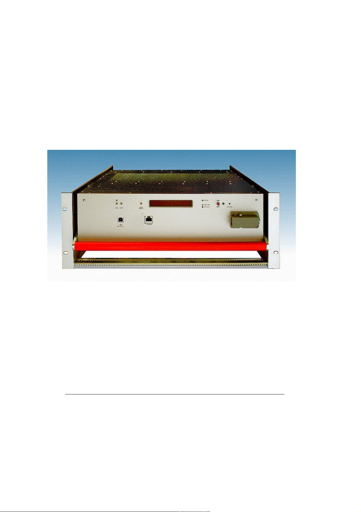
28. May 2013 1 *00679.A4
PL512/PL506
Modular Power Supply System
Technical Manual
Page 2

General Remarks
The only purpose of this manual is a description of the product. It must not be interpreted as
a declaration of conformity for this product including the product and software.
W-Ie-Ne-R revises this product and manual without notice. Differences of the description in
manual and product are possible.
W-Ie-Ne-R excludes completely any liability for loss of profits, loss of business, loss of use
or data, interrupt of business, or for indirect, special incidental, or consequential damages of
any kind, even if W-Ie-Ne-R has been advises of the possibility of such damages arising
from any defect or error in this manual or product.
Any use of the product which may influence health of human beings requires the express
written permission of W-Ie-Ne-R.
Products mentioned in this manual are mentioned for identification purposes only. Product
names appearing in this manual may or may not be registered trademarks or copyrights of
their respective companies.
No part of this product, including the product and the software may be reproduced,
transmitted, transcribed, stored in a retrieval system, or translated into any language in any
form by any means with the express written permission of W-Ie-Ne-R.
Control Cabinet
In the context of this user manual, the control cabinet must fulfill the requirements on fireprotective enclosures according to EN 60950 / IEC 60950 / UL 60950.
All devices are intended for operation in control cabinets or in closed areas. The LAN
connection and all wire connections between the different system parts must be done via
shielded cable with conductive connector shells, which are fixed with screws.
Furthermore, an additional fire-protective enclosure is required which must not affect proper
air circulation.
Mains Voltage and Connection
The Power supplies are equipped with a “World”- mains input (rated voltage range: 100-240
VAC, frequency: 50-60 Hz, rated current: 16 A). Before connecting to the mains please
double-check correspondence.
The mains input connection at the power supply side is described in chapter 2.1 (AC Mains
Connection) at page 2.
Safety
After connecting the Power box to the mains, the mains input module is powered
permanently. Filter and storage capacitors of the power factor correction module are charged
with about 400VDC. Any DC-On-Signal as well as a power switch at control board (if any
installed) operates as a low voltage DC on/off switch only and not as a mains breaker.
Therefore it becomes dangerous if the box cover is open. In this case a lot of
components on high voltage potential get touchable!
Before starting any kind of work inside the power box remove
the unit from mains and wait a couple of minutes with your
activities! Discharge the primary DC filter-capacitors by use of
a well insulated 22 ohm 10W resistor.
We recommend in case of any malfunction to send the power
box to Wiener or to one of our representative for service
2. April 2014 i *00679.A4
Page 3

Declaration of Conformity
Low Voltage Directive 73/23/EEC and EMC Directive Art. 10.1 of 89/336/EEC
W-Ie-Ne-R
Plein & Baus GmbH
declare under our own responsibility that the product
PL5 / PL6, F8-12
Items: 0P00.xxxx; 0P01.xxxx; 0P04.xxxx; 0M11.xxxx;
0M21.xxxx
is in accordance with the following standards or standardized documents:
1. EN 60 950-1:2001
+ Corr:2004-09
Niederspannungsrichtlinie [low voltage
directive]
2. EN 61 000-6-3:2001
Störaussendung EMA [RF emission]
EN 55 022:1998
+ Corr:2001 + A1:2000 Kl. B
Störspannung [conducted noise]
EN 55 022:1998
+ Corr:2001 + A1:2000 Kl. B
Störfeldstärke [radiated noise]
EN 61 000-3-2:2001 Oberschwingungen [harmonics]
EN 61 000-3-3:1995 +Corr:1997 +A1:2001 Spannungsschwankungen [flicker]
3. EN 61 000-6-2:2001 Störfestigkeit EMB [immunity]
EN 61 000-4-6:1996 + A1:2001 HF-Einströmung [injected HF currents]
EN 61 000-4-3:1996 + A1:1998 + A2:2001 HF-Felder [radiated HF fields] incl.
”900MHz”
EN 61 000-4-4:1995 + A1:2001 Burst
EN 61 000-4-5:1995 + A1:2001 Surge
EN 61 000-4-11:1994 + A1:2000 Spannungs-Variationen [voltage
variations]
EN 61 000-4-2:1995 + A1:1998 + A2:2001 ESD
Conditions:
This unit is not a final product and is foreseen for use inside a closed cabinet. The supplying
of loads over long distances (>3m) needs possibly additional RF rejection hardware to get in
conformity of the definition. Admitted for powering by all mains.
Name and signature of authorized person Place and Date
Juergen Baus
Techn. Director Aug. 2006
2. April 2014 ii *00679.A4
Page 4

Contents
General Remarks.............................................................................................................. i
Declaration of Conformity...............................................................................................ii
1 General Information............................................................................................................1
2 PL512/PL506 Power Box....................................................................................................2
2.1 AC Mains Connection................................................................................................ 2
2.2 Main Switch................................................................................................................ 3
2.3 USB Connector...........................................................................................................3
2.4 Ethernet Connector....................................................................................................3
2.5 Water Cooling Connection (Optional)......................................................................3
2.6 Global Reset Input (Optional)..................................................................................4
2.7 Channel-Wise Interlock Input (Optional)...............................................................5
2.8 Global Stop and Start Inputs (Optional)..................................................................5
2.9 Alphanumeric Display (Optional).............................................................................6
2.9.1 LED Description...................................................................................................7
2.9.2 Function of the Switches......................................................................................7
2.9.3 Main Operating Modes and Associated Submenus...............................................8
2.10 Power Output and Sense Connections PL512........................................................9
2.11 Power Output and Sense Connections PL506......................................................10
3 PL512/PL506 Control and Setup via USB........................................................................10
3.1 Installation................................................................................................................11
3.2 The Main Window.................................................................................................... 12
3.3 Description of the Menu Items................................................................................12
3.3.1 Read Power Supply Data From File Dialog.........................................................13
3.3.2 Output Configuration Dialog...............................................................................13
3.3.3 Global and Network Configuration Dialog..........................................................15
4 PL-506/512 Wiring and First Use Instructions ..............................................................16
4.1 Power Bins PBN506/PBN512..................................................................................16
4.2 Sense Connections / Mode........................................................................................16
4.3 Load Connections..................................................................................................... 17
4.4 MUSEControl...........................................................................................................18
5 Web Server........................................................................................................................21
6 SNMP Control...................................................................................................................21
7 OPC Server........................................................................................................................ 30
8 Power Bins PBN506/PBN512........................................................................................... 31
Appendix A: Data Sheet....................................................................................................... 33
Appendix B: Ordering Information......................................................................................36
Appendix C: SNMP OID Tree.............................................................................................37
Appendix D: Parallel Connection of Output Channels.........................................................40
2. April 2014 iii *00679.A4
Page 5

Figures
Figure 2.1: PL512/PL506 Front Side with Interlock and Water-Cooled Option..........2
Figure 2.2: PL512/PL506 Front Side with Display Option..........................................2
Figure 2.3: PL512 Rear Side (Power Output Connections)......................................9
Figure 2.4: PL506 Rear Side (Power Output Connections)....................................10
Figure 2.5: PL512 Rear Side (Power Output Connections)....................................10
Figure 7.1: PBN512 -3U RATO Power Bin..............................................................17
Figure 7.2: PBN506 -3U RASO Power Bin (with PL506 Power Supply inserted).....18
Figure 7.3: Current Bar Dimensions........................................................................26
Figure 7.4: Two Channels Parallel...........................................................................28
Figure 7.5: Three Channels Parallel........................................................................28
Figure 7.6: Four Channels Parallel..........................................................................28
Tables
Table 1: AC Mains Input Connector Pin Assignment.................................................2
Table 2: USB Connector Pin Assignment..................................................................3
Table 3: Ethernet Connector Pin Assignment............................................................3
Table 4: Global Reset Connector Pin Assignment.....................................................4
Table 5: Channel-Wise Interlock Connector Pin Assignment.....................................5
Table 6: Sense Connector Pin Assignment...............................................................9
2. April 2014 iv *00679.A4
Page 6
1 General Information
Features
● up to 12 independent processor controlled, potential free outputs
● up to 3 kW DC output power
● Programmable output voltage, current limit and rise/fall time
● Measurement of output voltages and current
● Fully controlled, programmable trip thresholds (min./max. sense voltage, max terminal
voltage, max. current, power, temperature)
● PC-Control (connected to USB) with free available software
● Ethernet connection IEEE 802.3 10BASE-T and IEEE 802.3u 100BASE-TX
● WWW-Server integrated, full control via SNMP protocol
● OPC server available
● Three different voltage regulation modes programmable: Fast – Moderate - Slow
● Extremely low noise and ripple
● CE conform EN 50 081/82 part 2 or 1, safety in accordance with EN 60 950
● Sinusoidal mains current EN 61000-3-2
● Optional alphanumeric display
● Optional global interlock
● Optional channel-wise interlock
● Optional direct water cooling
● Optional Power Bin: Exchange of the power box without disconnecting the cabling to the
load
28. May 2013 1 *00679.A4
Page 7
2 PL512/PL506 Power Box
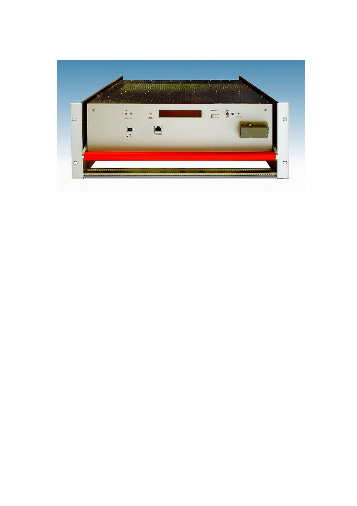
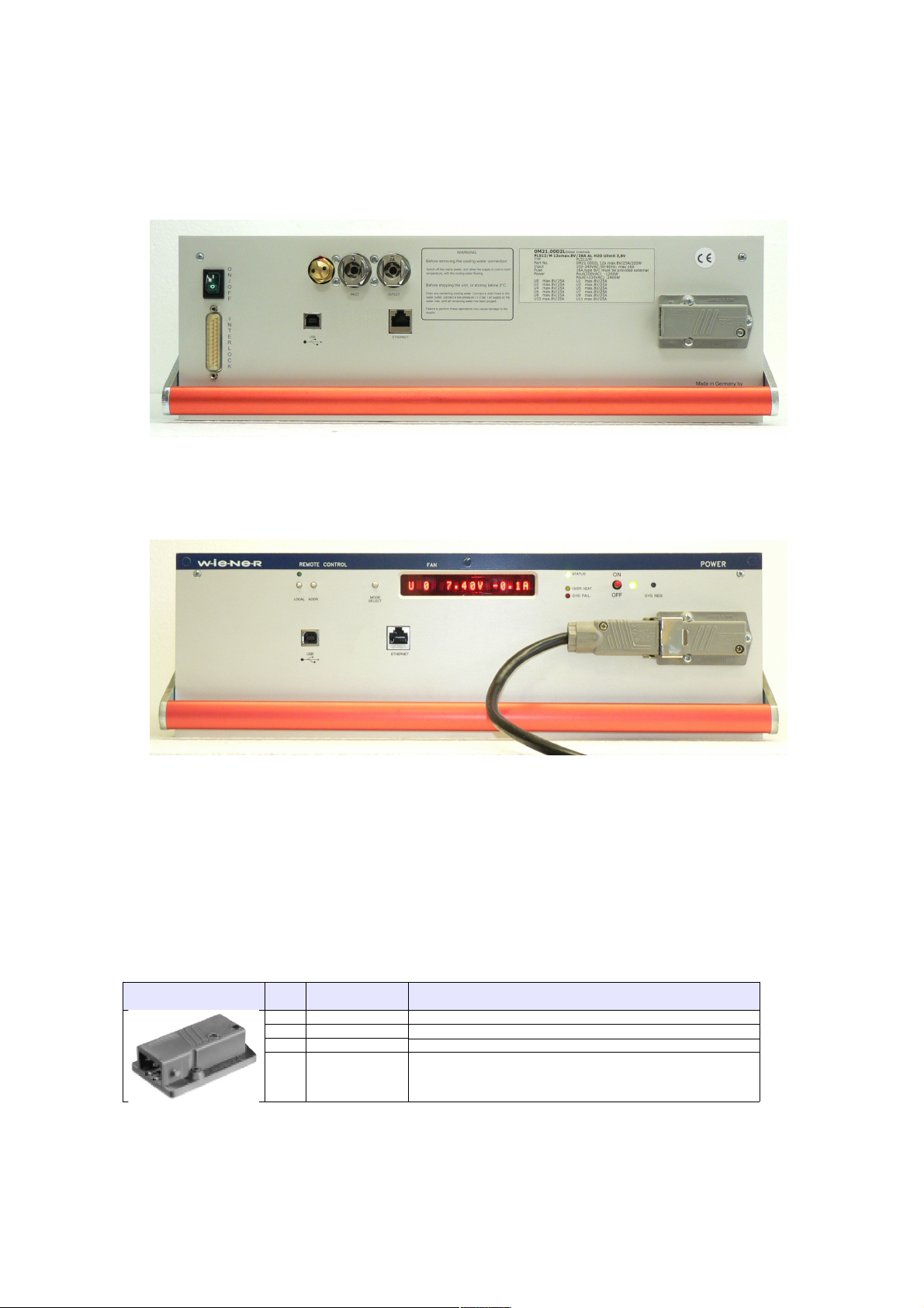
The PL512/PL506 front appearance differs slightly, depending on the existing options.
2.1 AC Mains Connection
The AC input connections are made with the Hirschmann connector series ST.
We recommend the mating cable plug STAK3N with the locking retainer STASI3.
AC Input Pin Signal Comment
1
Phase
2
Return, Neutral
Cable wire color: black or brown wire
Cable wire color: blue
3
unused
Earth Protective Earth Safety Ground, Cable wire color: green / yellow
Table 1: AC Mains Input Connector Pin Assignment
28. May 2013 2 *00679.A4
Figure 2.1: PL512/PL506 Front Side with Interlock and Water-Cooled Option
Figure 2.2: PL512/PL506 Front Side with Display Option
Page 8
2.2 Main Switch
The green illuminated rocker switch works as a global inhibit input.
● 0 Power outputs disabled
● I Switch is lighting, power outputs may be enabled by the remote control.
This switch is a logic switch only. It does not disconnect the mains supply.
With the Alphanumeric Display Option the switch is omitted.
2.3 USB Connector
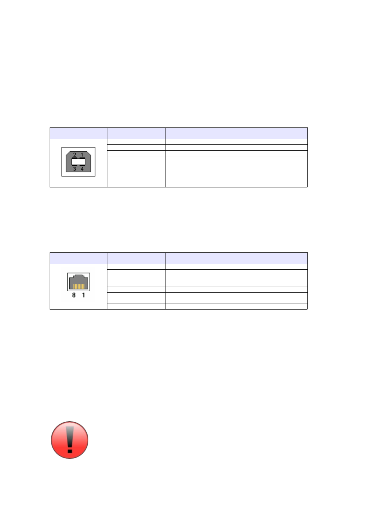
USB Socket Pin Signal Comment
1
VCC2D-3D+
4
GND
Table 2: USB Connector Pin Assignment
This is the standard USB connector type B.
2.4 Ethernet Connector
RJ45 Socket Pin Signal Comment
1
TX+2TX-
3
RX+
4
GND 1
5
GND 1
6
RX-
7
GND 2
8
GND 2
Table 3: Ethernet Connector Pin Assignment
This is the standard NIC configuration. You need a 1:1-cable to connect a to a HUB, or a cross-
over cable to connect to another NIC (e.g. a computer). There is no automatic signal crossing like
with some routers.
2.5 Water Cooling Connection (Optional)
The water connections are made with quick couplings series LC 6.4 mm from Colder Products
Company (CPC). We recommend an elbow mating plug with shutoff, e.g. LCD230-04.
Consider that water inlet and water outlet are not exchangeable.
The safety valve may not be readjusted by the customer.
28. May 2013 3 *00679.A4
Page 9
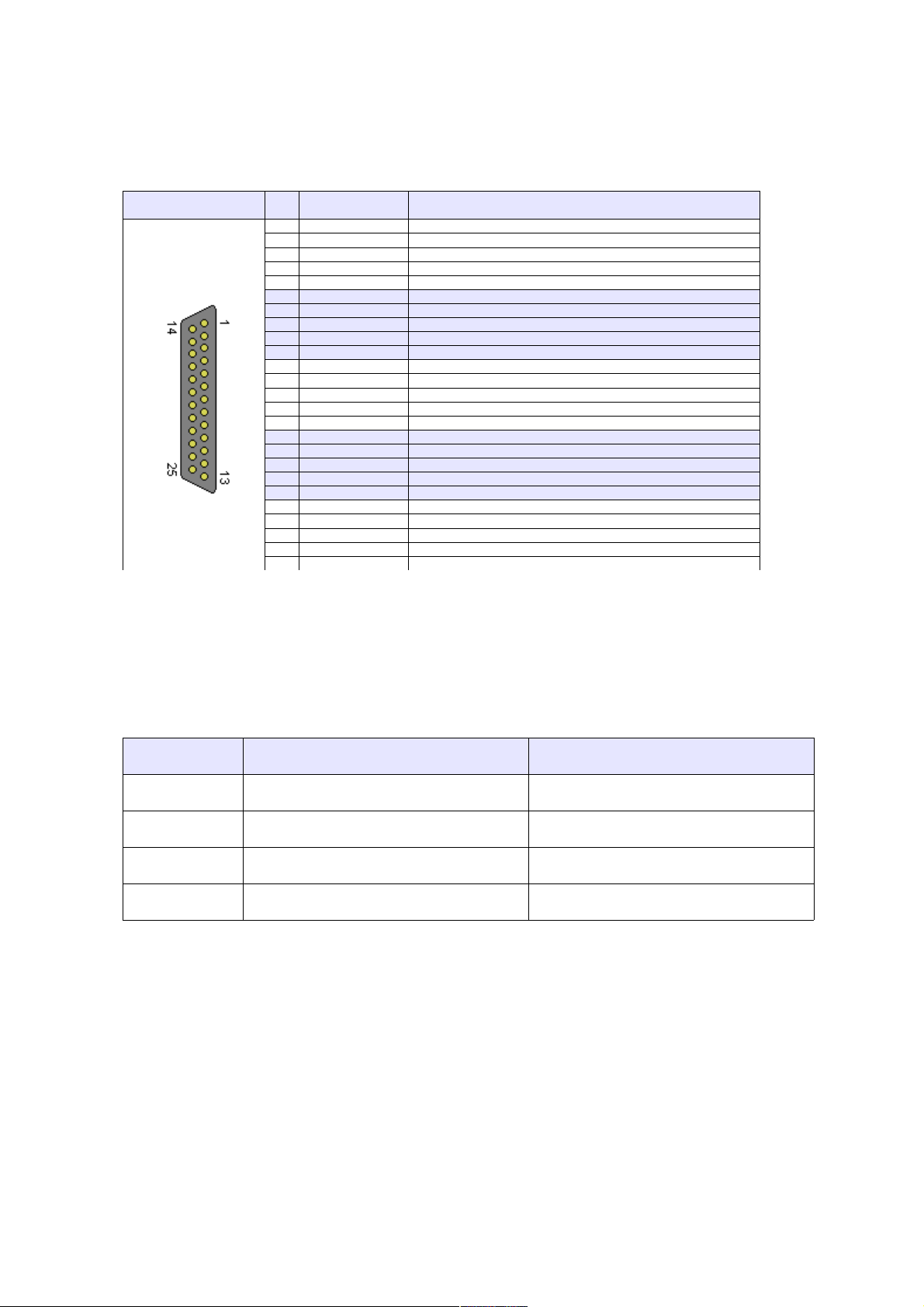
2.6 Global Reset Input (Optional)
The global reset input (POWER_INHIBIT) is provided to force all outputs to be switched off.
● connected to GND Power outputs disabled
● floating Power outputs may be enabled by the remote control
DSUB25 female Pin Signal Comment
1NCreserved
14NCreserved
2NCreserved
15NCreserved
3NCreserved
16NCreserved
4NCreserved
17NCreserved
5NCreserved
18NCreserved
6NCreserved
19NCreserved
7NCreserved
20NCreserved
8NCreserved
21NCreserved
9NCreserved
22NCreserved
10NCreserved
23NCreserved
11NCreserved
24NCreserved
12NCreserved
25
GND
Ground of the aux. supply, connected to USB ground
13
POWER_INHIBIT
Inhibit input
Table 4: Global Reset Connector Pin Assignment
The signals shall be connected by an isolated contact (e.g. relays), and must not be connected to
other potentials.
The input has an internal 10 kΩ pull-up resistor to 5V and an input impedance of 10 kΩ.
It is possible to invert the logic of this signal by changing a jumper switch inside of the power box..
Jumper at Pin POWER_INHIBIT Input Functionality
1 – 2 open power disabled (INTERLOCK)
connected to GND power enabled
2 – 3 open power enabled
connected to GND power disabled (RESET)
28. May 2013 4 *00679.A4
Page 10
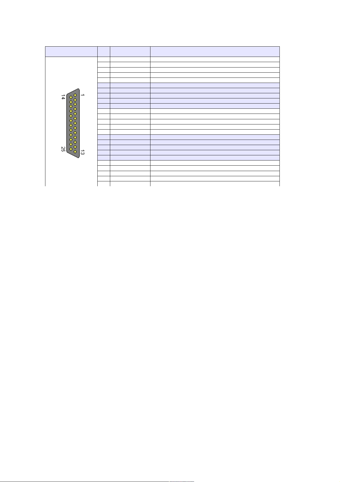
2.7 Channel-Wise Interlock Input (Optional)
The channel-wise interlock inputs are provided to force a dedicated output to be switched off.
DSUB25 female Pin Signal Comment
1
Interlock U0 +
14
Interlock U0 -
2
Interlock U1 +
15
Interlock U1 -
3
Interlock U2 +
16
Interlock U2 -
4
Interlock U3 +
17
Interlock U3 -
5
Interlock U4 +
18
Interlock U4 -
6
Interlock U5 +
19
Interlock U5 -
7
Interlock U6 +
20
Interlock U6 -
8
Interlock U7 +
21
Interlock U7 -
9
Interlock U8 +
22
Interlock U8 -
10
Interlock U9 +
23
Interlock U9 -
11
Interlock U10 +
24
Interlock U10 -
12
Interlock U11 +
25
Interlock U11 -
13
reserved
Table 5: Channel-Wise Interlock Connector Pin Assignment
Each interlock input is galvanically isolated (optocouplers). If a channel is interlocked, it is not
possible to switch it on.
Signal level:
interlocked: -10 V ... +0.8 V
not interlocked: +2.2 V ... +10 V (input impedance 1 kΩ + LED, so higher input
voltages can be used if an external resistor is implemented.)
2.8 Global Stop and Start Inputs (Optional)
This inputs allow to switch off the outputs channels (emergency stop) or to switch on all power
supply outputs (e.g. used for maintenance) .
28. May 2013 5 *00679.A4
Page 11
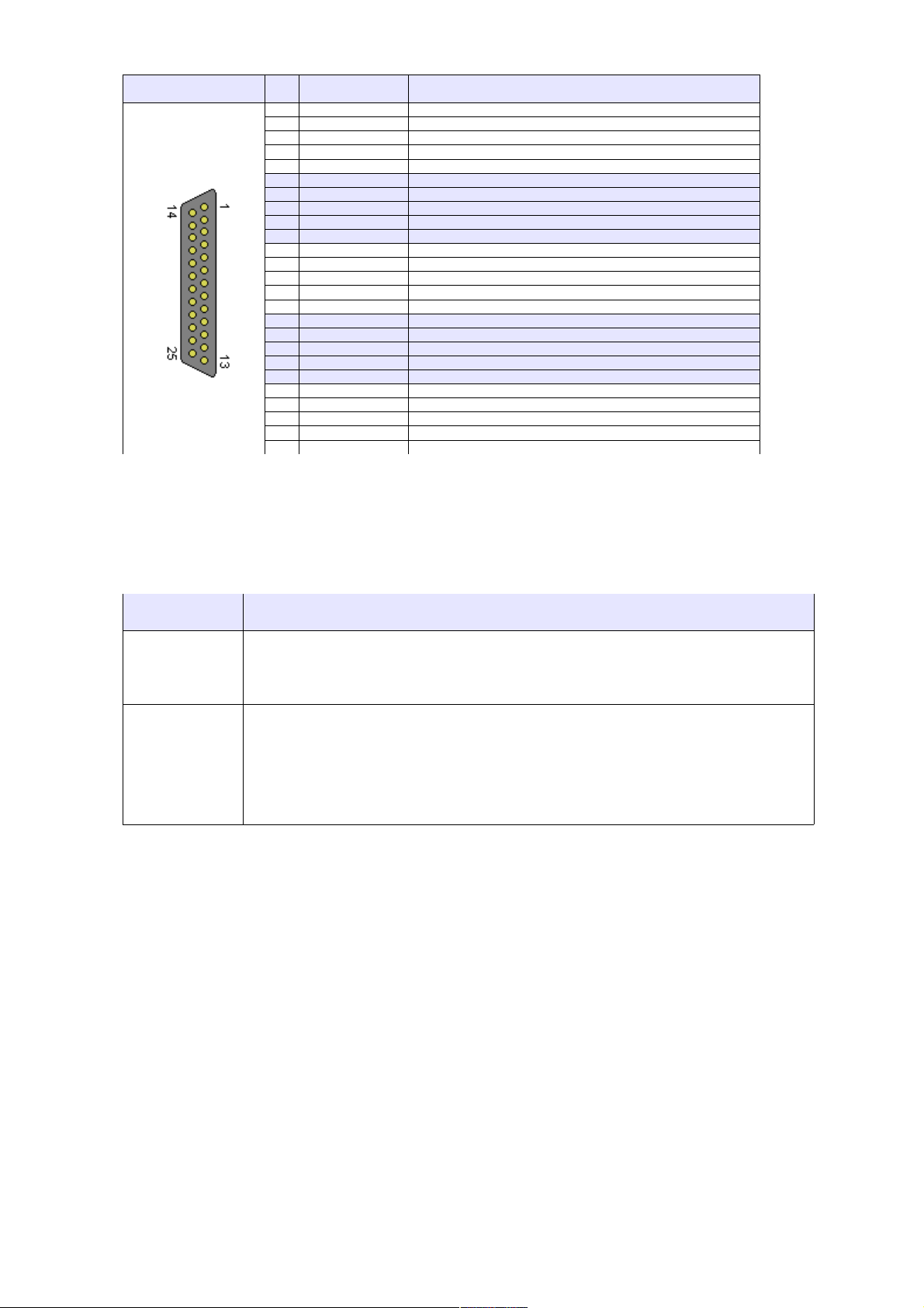
DSUB25 female Pin Signal Comment
1NCreserved
14NCreserved
2NCreserved
15NCreserved
3NCreserved
16NCreserved
4NCreserved
17NCreserved
5NCreserved
18NCreserved
6NCreserved
19NCreserved
7NCreserved
20NCreserved
8NCreserved
21NCreserved
9NCreserved
22NCreserved
10NCreserved
23NCreserved
11NCreserved
24NCreserved
12
STOP
reserved
25
GND
Ground of the aux. supply, connected to USB ground
13
START
Inhibit input
Table 6: Global Stop and Start Connector Pin Assignment
The signals shall be connected by a dry contact (e.g. relay), and must not be connected to other
potentials.
The input has an internal 330 Ω pull-up resistor to 5V and an input impedance of 1 kΩ.
Signal Functionality
STOP If this signal is connected to GND (dry contact close), all power supply outputs
are switched off. This functionality has priority over all other functions, it is not
possible to switch outputs on in this state
START If this signal is connected to GND (dry contact close), all power supply outputs
are switched on. They will only be switched off in case of an emergency switch
off caused by the supervision logic of the power supply.
If this signal is not connected (dry contact open), power supply outputs may be
switched on/off via SNMP or with the display control.
2.9 Alphanumeric Display (Optional)
This option allows the setup and display of some power supply items with toggle switches.
28. May 2013 6 *00679.A4
Page 12

2.9.1 LED Description
● Power LED (green, 5mm) Lighting if the PL512/PL506 is operating. Channels may be
on.
● Status LED (green, 3mm) Lighting if the main processor is working properly .
● Overheat (yellow) Lighting if the operating temperature inside of the
power supply is too high.
● SYS FAIL (red) Processor malfunction.
2.9.2 Function of the Switches
After the PL512/PL506 has been switched on by pushing the “Power” switch up, the main operation
modes can be selected by pushing the “Mode Select” switch up or down.
Many main operating modes do have one or more submenus, which can be accessed by a special
procedure.
You will use the following switches of the PL512/PL506:
Symbol Description Remarks
P▲ Push “Power” switch up (ON) Main power supply is off:
Switch the power supply on. All power
channels are off.
Display shows a switched off channel:
Switch this channel on.
Submenu:
OK button. Used to enter the selected
submenu, request to change a value, accept
the changes.
P▼ Push “Power” switch down
(OFF)
Display shows a switched off channel:
Switch the main power supply and all
channels off.
Display shows a switched on channel:
Switch this channel off.
Submenu:
CANCEL button. Used to leave a submenu,
discard the changes.
M▲ Push “Mode Select” switch up Main operating mode:
Select the next operating mode.
Submenu:
Change the selected item to the next possible
state.
M▼ Push “Mode Select” switch
down
Main operating mode:
Select the previous operating mode.
Submenu:
Change the selected item to the previous
possible state.
28. May 2013 7 *00679.A4
Page 13
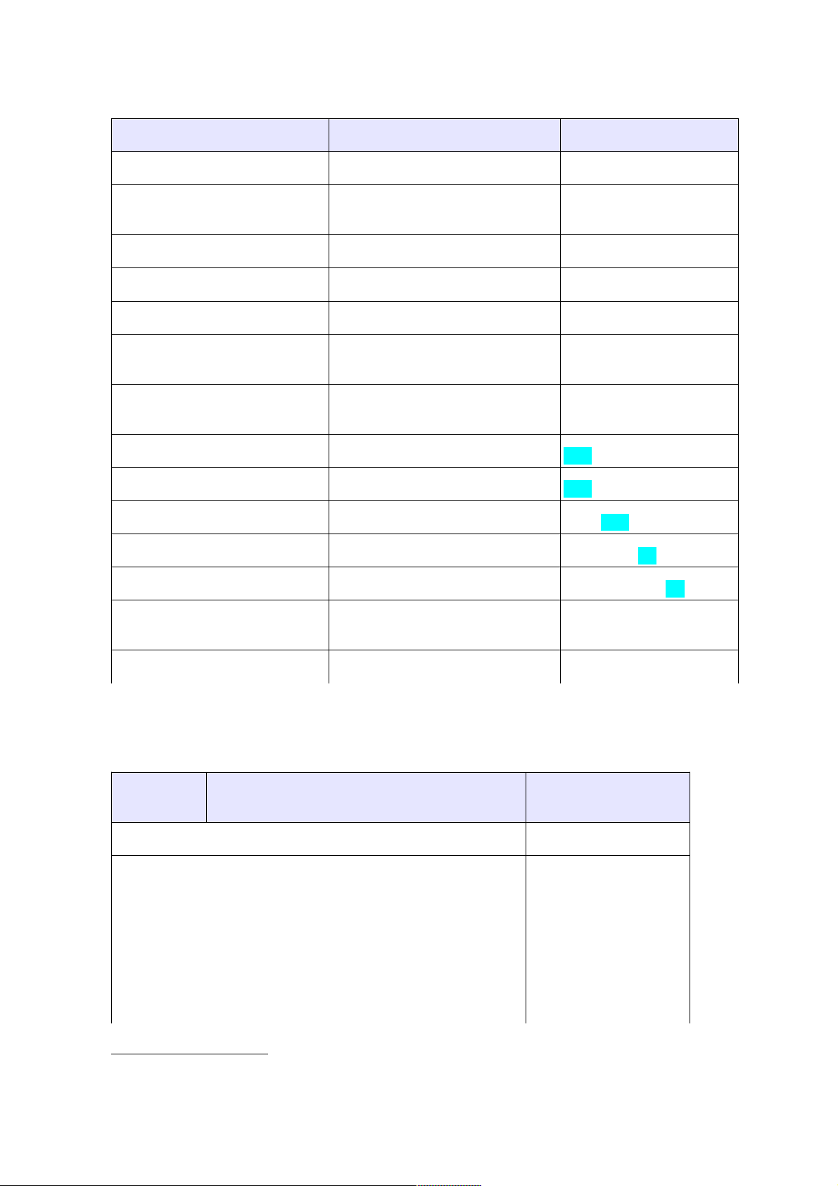
The following example describes the detailed steps to enter a sub menu and change the IP gateway
address.
Description Switch Display
1
switch the crate on P▲ U0 5.01V 1.2A
select the requested main
operation mode
M▲ or M▼ (until right mode is
displayed)
TCPIP: no link
enter submenu M▲(push and hold), P▲ Config: Wait
hold both switches up Config: Wait...
after 4 seconds you can Config: Ready !
release the switches TCPIP Address
192.168.91.80
Select submenu “TCPIP
Gateway”
M▲ or M▼ (until right menu is
displayed)
TCPIP Gateway
192.168.91.94
Enter this menu P▲ 192.168.91.94
Change the value M▲ or M▼ 196.168.91.94
Accept change, to next item P▲ 196.168.91.94
Accept change, to next item P▲ 196.168.91.94
Accept change, to next item P▲ 196.168.91.94
Ready, back to submenu
selection
P▲ TCPIP Gateway
196.168.91.94
Ready, leave submenu M▼ TCPIP: no link
2.9.3 Main Operating Modes and Associated Submenus
Operating
Mode
Submenu Display
Display voltage and current of the selected output channel U0 5.01V 72.A
Display the TCP/IP connection state
Possible values & symbols are:
no link (no cable connected)
10M (connected to 10M network)
100M (connected to 100M network)
HD (half duplex)
FD (full duplex)
↓, ↑, ↕ (Frame received, transmitted, both)
Ethernet 100M FD
1 Display: Two lines: displayed alternating, alternate background color: blinking
28. May 2013 8 *00679.A4
Page 14
Operating
Mode
Submenu Display
Change the TCP/IP address TCPIP Address
192.168.91.80
Change the TCP/IP subnet mask TCPIP SubnetMask
255.255.255.224
Change the TCP/IP gateway address TCPIP Gateway
192.168.91.94
Allow writes (e.g. switch on/off) via the web
server
HTTP:read/write
Change TCP/IP negotiation settings TCPIPnegotiation
AutoNegotiation
Display of the ethernet hardware address (MAC).
This address is written at the type plate, too.
TCPIP MAC Addres
0050-C22D-C231
Change the TCP/IP port of the web server HTTP Port 80
Change the TCP/IP port of the SNMP server SNMP Port 161
Restore the default SNMP settings (community
strings)
SNMP Default No
2.10 Power Output and Sense Connections PL512
Figure 2.3: PL512 Rear Side (Power Output Connections)
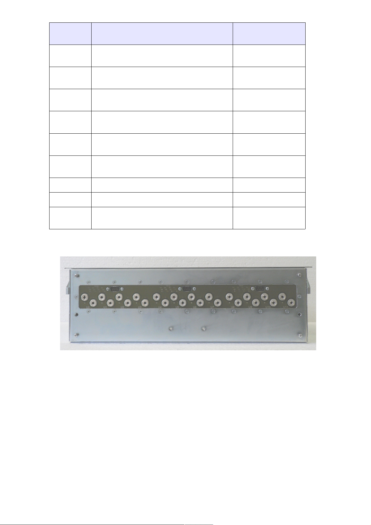
The low voltage DC output at the rear side of the power supply is provided by 4 mm sockets The
channels are arranged from left to right starting with U0. Positive output is up and negative output is
down.
28. May 2013 9 *00679.A4
Page 15
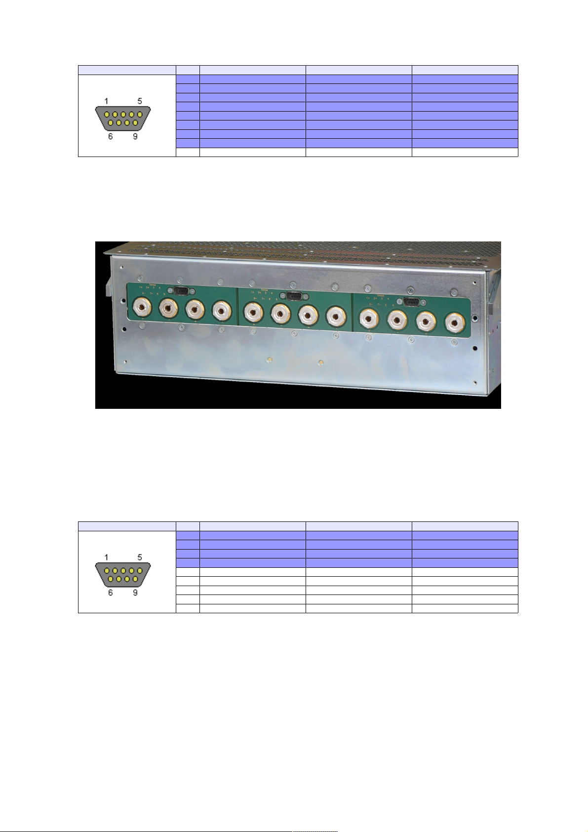
The sense lines are routed to three DSUB connectors (four channels each).
SUB9 male Pin Left Connector (U0..U3) Middle Connector (U4..U7) Right Connector (U8..U11)
1 U0 Sense + U4 Sense + U8 Sense +
6 U0 Sense - U4 Sense - U8 Sense 2 U1 Sense + U5 Sense + U9 Sense +
7 U1 Sense - U5 Sense - U9 Sense 3 U2 Sense + U6 Sense + U10 Sense +
8 U2 Sense - U6 Sense - U10 Sense 4 U3 Sense + U7 Sense + U11 Sense +
9 U3 Sense - U7 Sense - U11 Sense 5 not connected not connected not connected
Table 7: Sense Connector Pin Assignment
2.11 Power Output and Sense Connections PL506
Figure 2.5: PL506 Rear Side (Power Output Connections)
The low voltage DC output at the rear side of the power supply is provided by 6 mm or 8mm sockets
. The channels are arranged from left to right starting with U0. Positive output is up and negative
output is down.
The sense lines are routed to three DSUB connectors (2 channels each).
DSUB9 male Pin Left Connector (U0..U3) Middle Connector (U4..U7) Right Connector (U8..U11)
1 U0 Sense + U2Sense + U4 Sense +
6 U0 Sense - U2Sense - U4 Sense 2 U1 Sense + U3Sense + U5 Sense +
7 U1 Sense - U3Sense - U5 Sense 3 not connected not connected not connected
8 not connected not connected not connected
4 not connected not connected not connected
9 not connected not connected not connected
5 not connected not connected not connected
Table 8: Sense Connector Pin Assignment
3 PL512/PL506 Control and Setup via USB
The PL512/PL506 can be controlled with the MUSEcontrol software. Without the Display option
this is the only way to change the network (TCP/IP) settings.
28. May 2013 10 *00679.A4
Figure 2.4: PL506 Rear Side (Power Output Connections)
Page 16
The USB interface is primarily intended to be used to configure the power
supply. The Ethernet connection is designated for remote control and
monitoring.
Requirements
● X86-Computer with USB connection (USB2 recommended)
● Microsoft Windows XP/VISTA/& or W8
Features
● Setup of the TCP/IP network parameters
● Global overview of all power supply channels
● Detailed configuration of the power supply channels
● Save and reload of configuration data
3.1 Installation
The installation software (MUSEcontrol-x.x.x.x.msi) is free available at the download area of our
website (www.wiener-d.com → Support → Downloads).
Please install the software before connecting the power supply to the USB. The
necessary USB-driver is included in the installation.
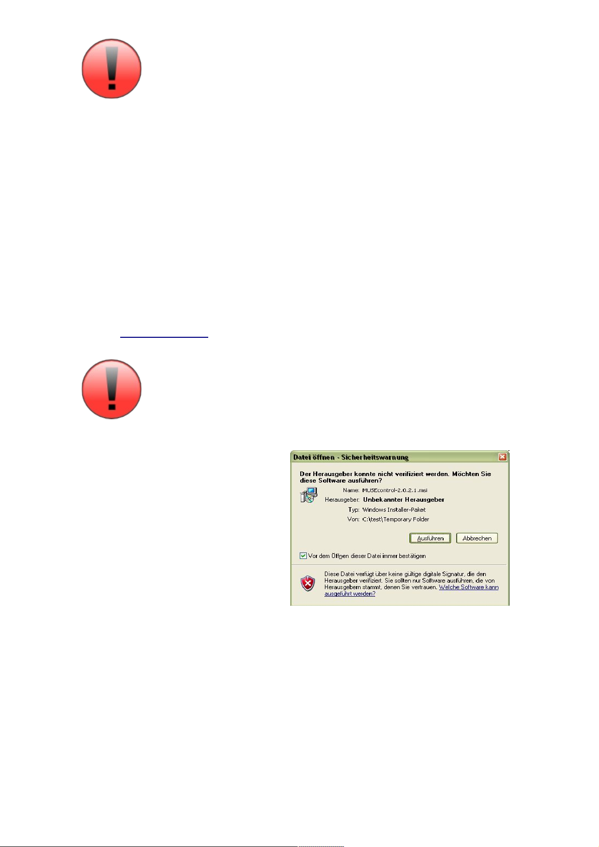
After downloading and executing the
software Windows may complain that the
supplier of the software could not be
verified. Ignore this warning and select
“Execute”.
Next the MUSEcontrol Setup Wizard
welcome screen is displayed. Click “Next”,
accept the license agreement and take a
look at the ReadMe notes.
Now you may change the default
installation folder and start the installation.
Now connect the PL512/PL506 with your
mains supply and use an USB cable to connect the computer with the PL512/PL506.
The computer will detect the new connected hardware and ask to connect to Windows Update.
Select “No” and click “Continue”.
Then accept the “Automatic install the software” selection by clicking “continue”.
28. May 2013 11 *00679.A4
Page 17
Now the USB driver software be installed. To access your power supply, execute the “WIENER
USB Power Supply Control” application via your start menu.
3.2 The Main Window
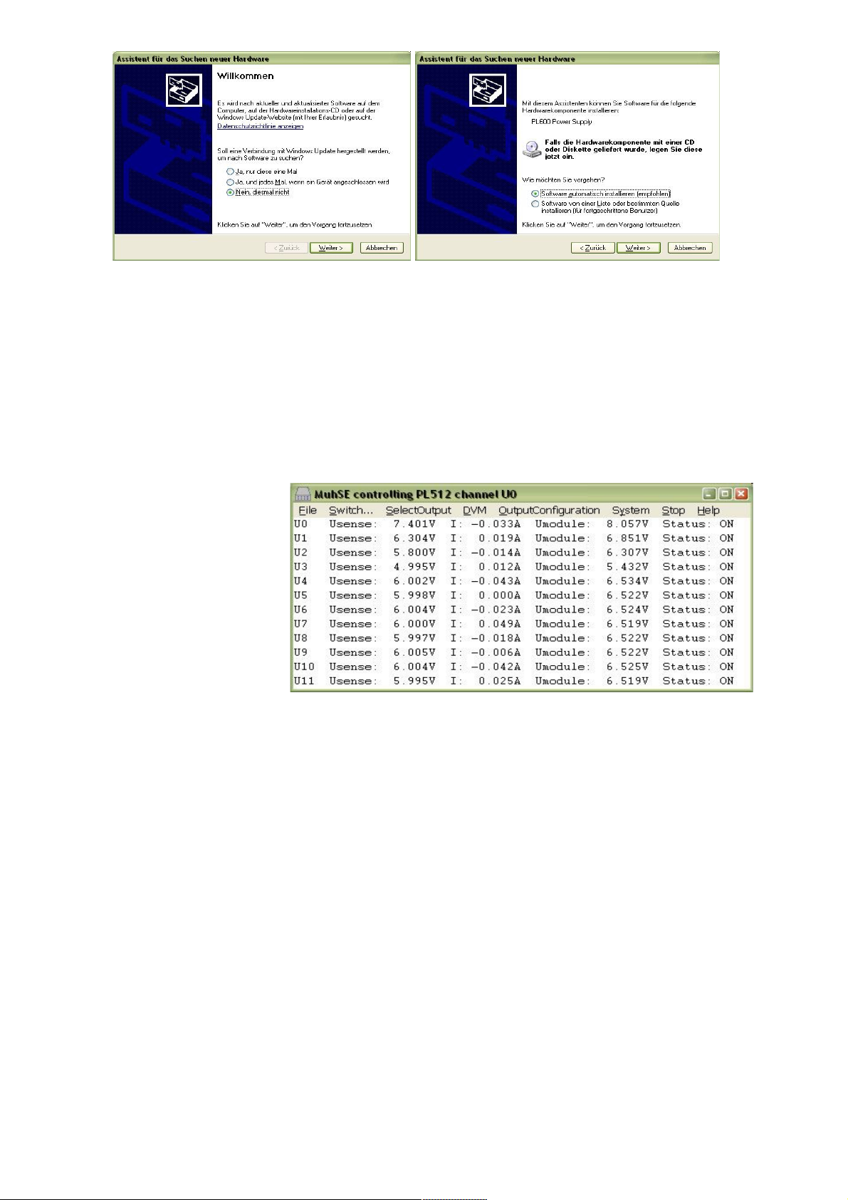
After starting the application the main window shows a channel overview.
The measured sense voltage (Usense), current (Imodule) and terminal voltage (Umodule) and a
global status of each
channel are displayed.
Clicking with the left
mouse button at a
channel toggles the
power state (OFF → ON
or ON → OFF).
Clicking with the right
mouse button opens the
output configuration
menu of this channel.
3.3 Description of the Menu Items
● File » Read Power Supply Configuration from File
Opens the Read Power Supply Data From File Dialog.
● File » Save Power Supply Configuration to File
Saves the complete power supply configuration to disk.
● Switch » All On
● Switch » All Off
Switches all power supply channels on or off.
● Switch » Group 1 On
● Switch » Group 1 Off
● Switch » Group 2 On
● Switch » Group 2 Off
This are commands to demonstrate the grouping functions of the PL512/PL506. The default
factory setting is group 1 for channels 0..5 and group 2 for channels 6..11.
● SelectOutput
28. May 2013 12 *00679.A4
Page 18
Select the next existing channel for the other dialogs. The current channel is displayed at the
title bar.
● DVM
Opens a large window showing the measurement data of one channel.
● OutputConfiguration
Opens the Output Configuration Dialog.
● OutputCalibration
This dialog is reserved for service personal.
● System » Configuration
Opens the Global and Network Configuration Dialog.
● System » Firmware Update
Allows to update the firmware of the main processor.
● Stop
● Start
Allow to interrupt and resume the communication with the PL512/PL506.
● Help » Info
Here you have access to the version number of the software.
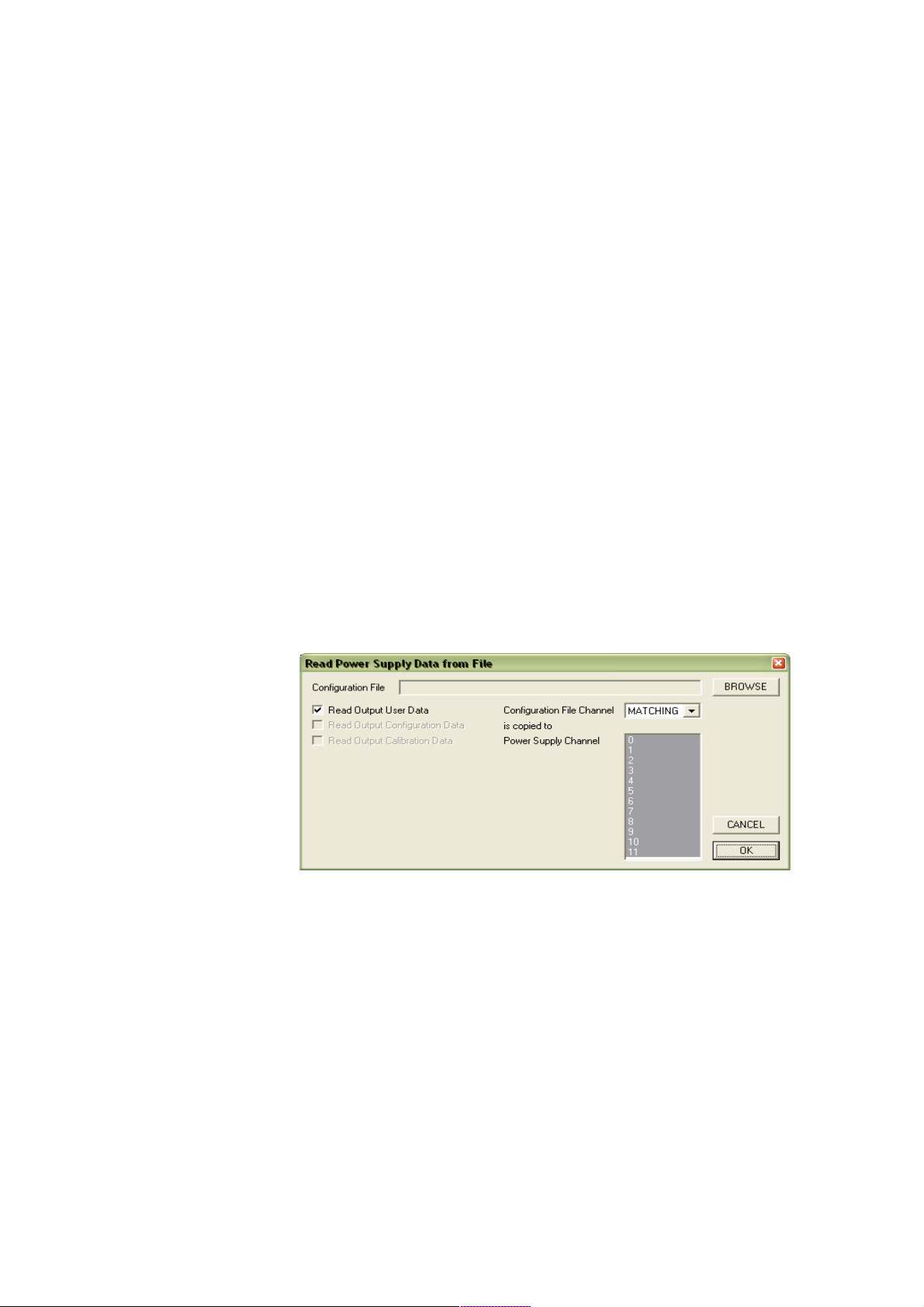
3.3.1 Read Power Supply Data From File Dialog
This dialog can be used to copy a XML configuration file from disk to the PL512/PL506.
It is possible to copy
each configuration file
channel to its
corresponding power
supply channel (e.g.
U0 → U0, U1 →
U1, ...) or to copy one
configuration file
channel to multiple
power supply
channels.
3.3.2 Output Configuration Dialog
This dialog allows the detailed configuration of each power supply channel.
The Measurement group shows the measured sense voltage, terminal voltage and current. The sense
voltage is the voltage at the sense lines, which are connected to the load. Terminal voltage means the
voltage at the terminals of the PL512/PL506.
Depending on the used modules, an analog or digital value of the most critical point of the power
module is displayed.
The power of the load and the output power of the module are calculated values.
28. May 2013 13 *00679.A4
Page 19
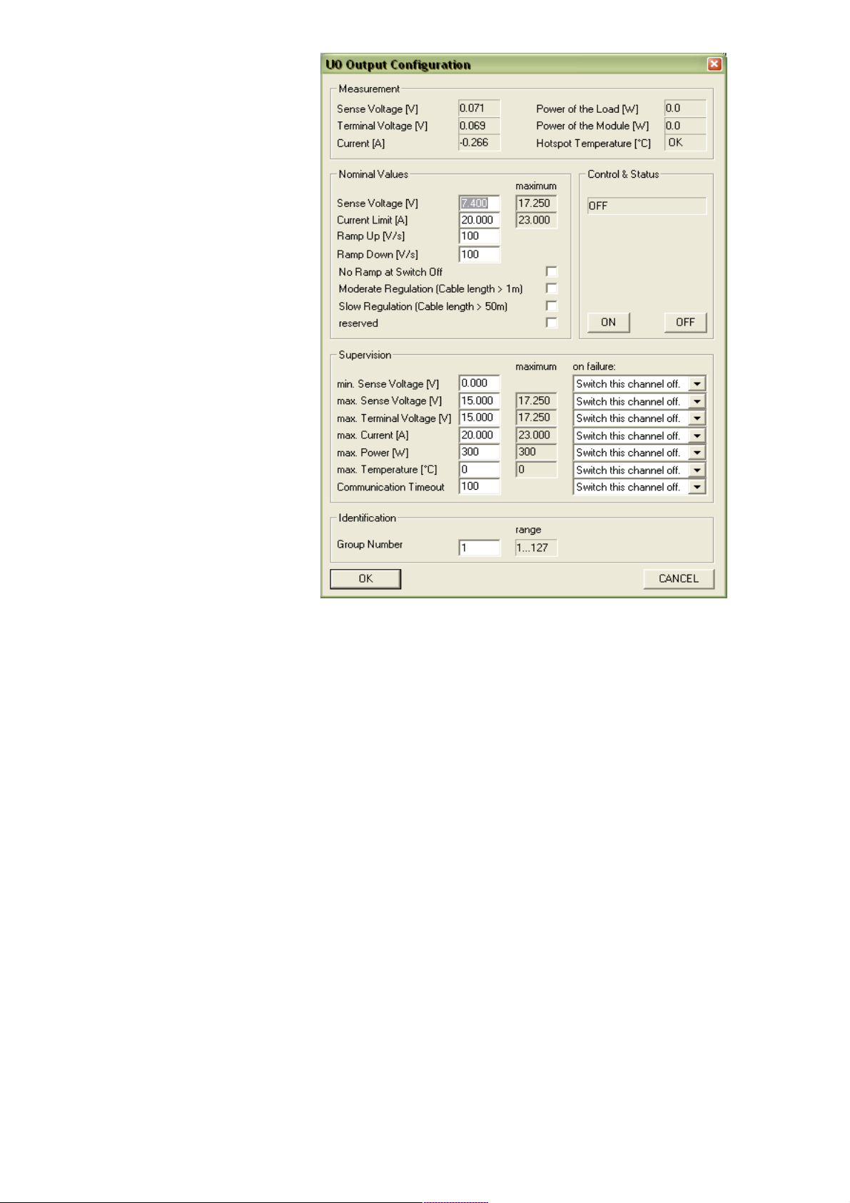
In the Nominal Values group
the nominal values of the
output voltage, the maximum
current which the power
supply will source before it
switches into constantcurrent mode, and the
voltage rise and fall rates are
entered.
If the No Ramp at Switch Off
check box is checked, the
Ramp Down value is only
used if the nominal voltage is
changed. If the voltage is set
to 0, the channel ramps down
to zero and than switches off.
But using the OFF button to
switch off cuts off the output
voltage immediately.
The voltage regulation
parameters can be modified
with the Moderate
Regulation check box. If
unchecked, the standard (PI)
regulator is used. This is the
fastest regulation, but may
start ringing with wires to the
load longer than 1 meter.
In this situations the
advanced (PID) regulator of
the Moderate Regulation
should be used.
If the load is connected with really long or high-inductance cable, the Slow Regulation check box
should be checked additionally. This increases the time constant of the I-Regulator.
The Control and Status group has buttons to switch the channel on or off. In case of any errors they
are displayed here, too.
The Supervision group contains all items which the microcontroller can observe. In case of
exceeding a limit, a dedicated action can be assigned to each item.
It is possible to
● ignore the failure (not possible at max. terminal voltage, max power and max. temperature:
the power supply has to protect itself)
● switch this channel off
● switch all channels with the same group number off
● switch all channels of the power supply off
The Identification group contains just a single item, the group number of the channel.
Many SNMP network commands can address a single channel (identified by the channel number) or
a group (identified by the group number), so it is possible to access different channels with only one
network message.
28. May 2013 14 *00679.A4
Page 20
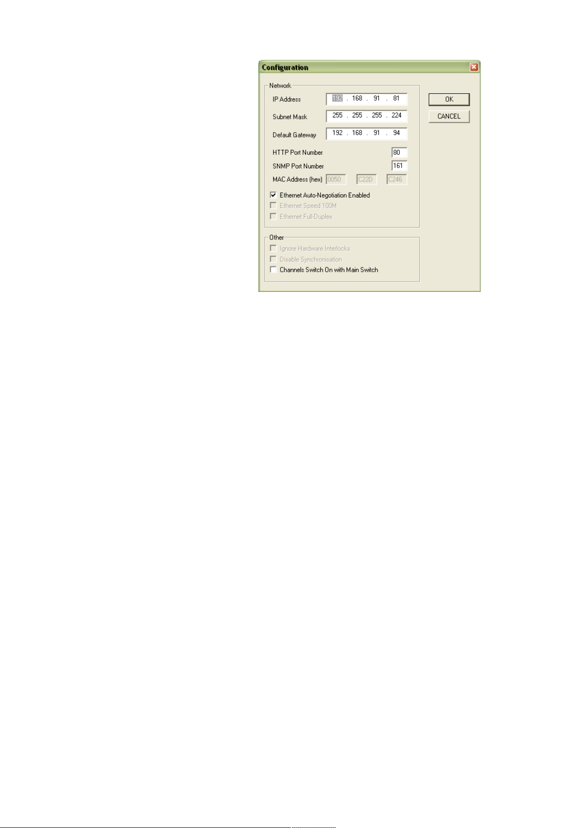
3.3.3 Global and Network Configuration Dialog
In the Network group box you enter the
TCP/IP network settings (IP address,
subnet mask and default gateway). You
have to use the parameters of your
local network here. Please contact your
network administrator for details.
HTTP and SNMP port numbers should
only modified if you know what you
do. Setting any port to 0 disables the
server.
If the “Channels Switch On with Main
Switch” check box in the Other group
box is checked, all output channels are
switched on if the main switch is
switched on.
28. May 2013 15 *00679.A4
Page 21
4 PL-506/512 Wiring and First Use Instructions
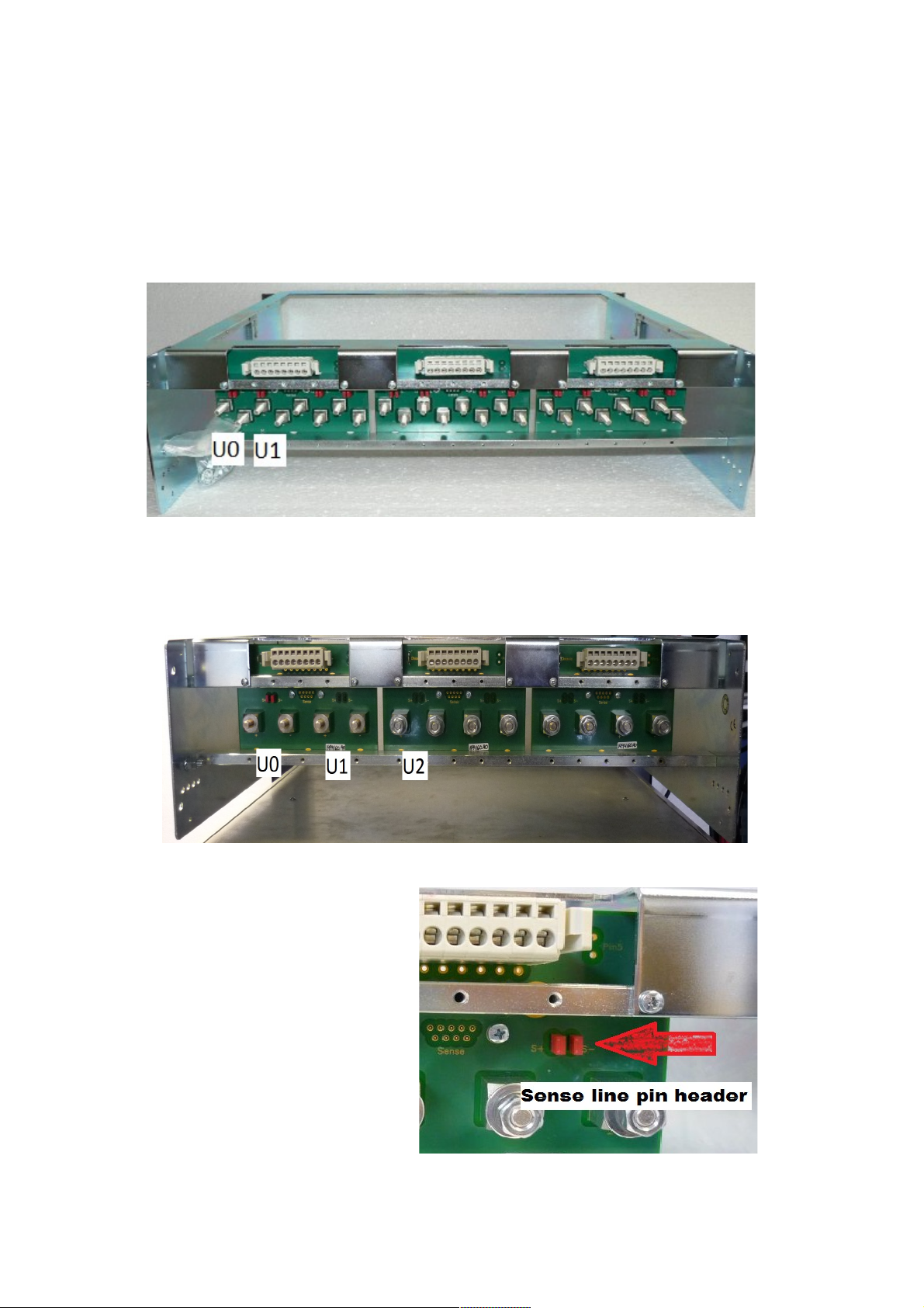
4.1 Power Bins PBN506/PBN512
For easy exchange of the PL506 or PL512 Power Supply, (PS), the special bins PBN506/PBN512
are provided. The low voltage/high current cabling is connected to M6/M5 threaded bolts. For the
PL-512: Starting from left with U0, positive outputs up – negative outputs down.
Each sense connector of four output channels are connected to an eightfold plug-able terminal row.
For the PL-506: Starting from left with U0+ and right U0-. Each sense line of two output channels
are connected to an eightfold plug-able terminal row. Last four terminals are unused.
4.2 Sense Connections / Mode
Jumper on: internal sense used,
No Jumper : external sense enabled
28. May 2013 16 *00679.A4
Fig. 4.1: PL-512 Power Bin, PBN512
Fig 4.2: PL-506 Power Bin, PBN506
Fig. 4.3: PL-506, Sense Pin Header Jumpers
Page 22
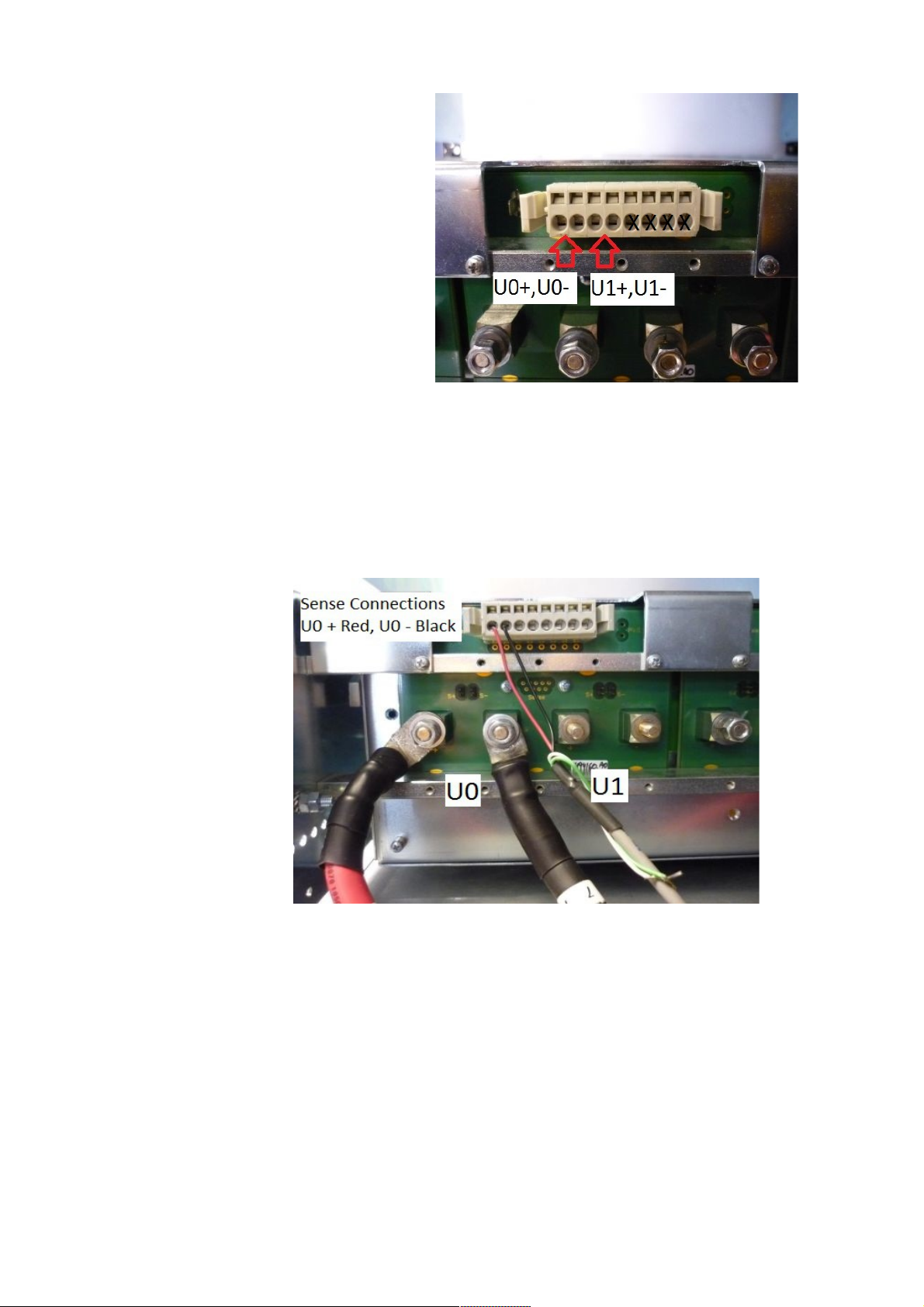
Use the plug-able sense connector for
sense wiring. The PL-506 has only 4
sense connections per terminal block
whereas the PL-512 has 8.
4.3 Load Connections
Looking from the rear of the PS, the load connections are as follows: from left to right U0, U1, U2,
U3 and so on. Fig.4.5- shows load and sense connections for U0. Use remote sense for load lines
greater than 1m.
Use internal sense for testing and setup only! Once your load and load lines are setup, then connect
sense lines for the most accurate control of load voltage and current.
28. May 2013 17 *00679.A4
Fig 4.4: PL-506, sense connector for U0 and U1
Fig. 4.5: PL-506- external sense
Page 23
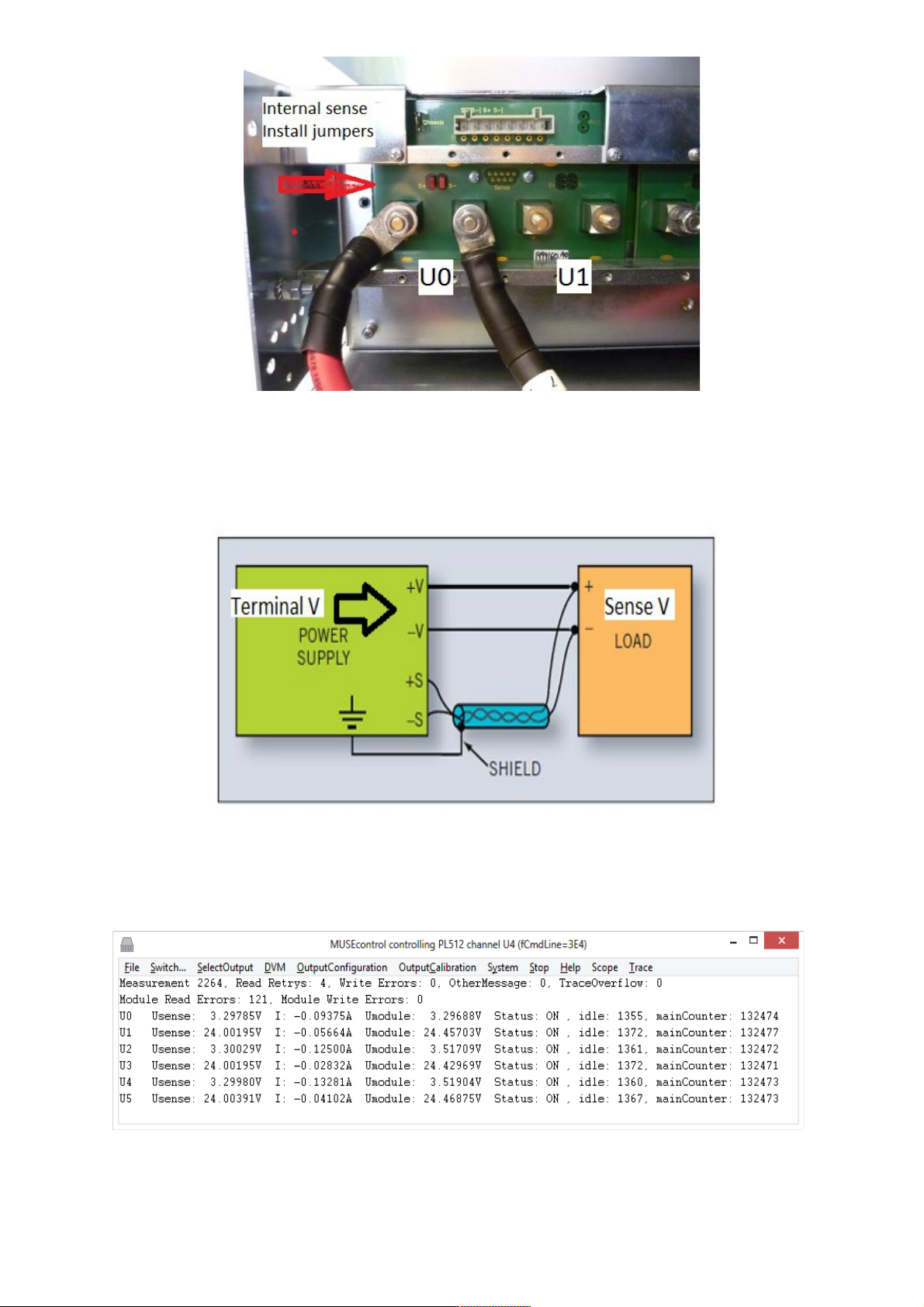
Use shielded twisted cable for the sense lines. For the load lines use twisted cable to cancel EMI,
(not shown in picture). Size the load lines appropriately for V drop and loads.
4.4 MUSEControl
28. May 2013 18 *00679.A4
Fig. 4.6: PL-506-internal sense
Fig. 4.7: Typical PS output wiring diagram
Fig. 4.8: PL-506, MUSEControl Main Window
Page 24
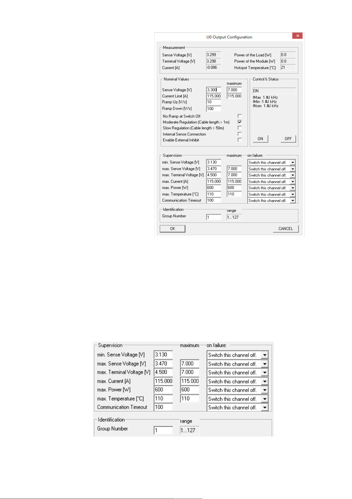
Right click on a channel to open the
Output Configuration Window.
The PS has supervision controls to
protect itself and loaded circuits.
The user has complete control of PS
parameters. The channel will not
operate properly or even turn on
without setting up the parameters
correctly.
Supervision:
Decide what is the permissible range of Sense Voltage[V]? Enter those values here,
Eg 3.130V and 3.470V respectively
Enter the maximum Terminal Voltage[V] permitted. The Terminal Voltage, will be higher than
sense voltage as discussed previously. Eg 4.50V
Enter the max, Current, Eg 115A or less.
28. May 2013 19 *00679.A4
Fig. 4.9: U0 Output Configuration
Fig. 4.10: Supervision Parameters
Page 25
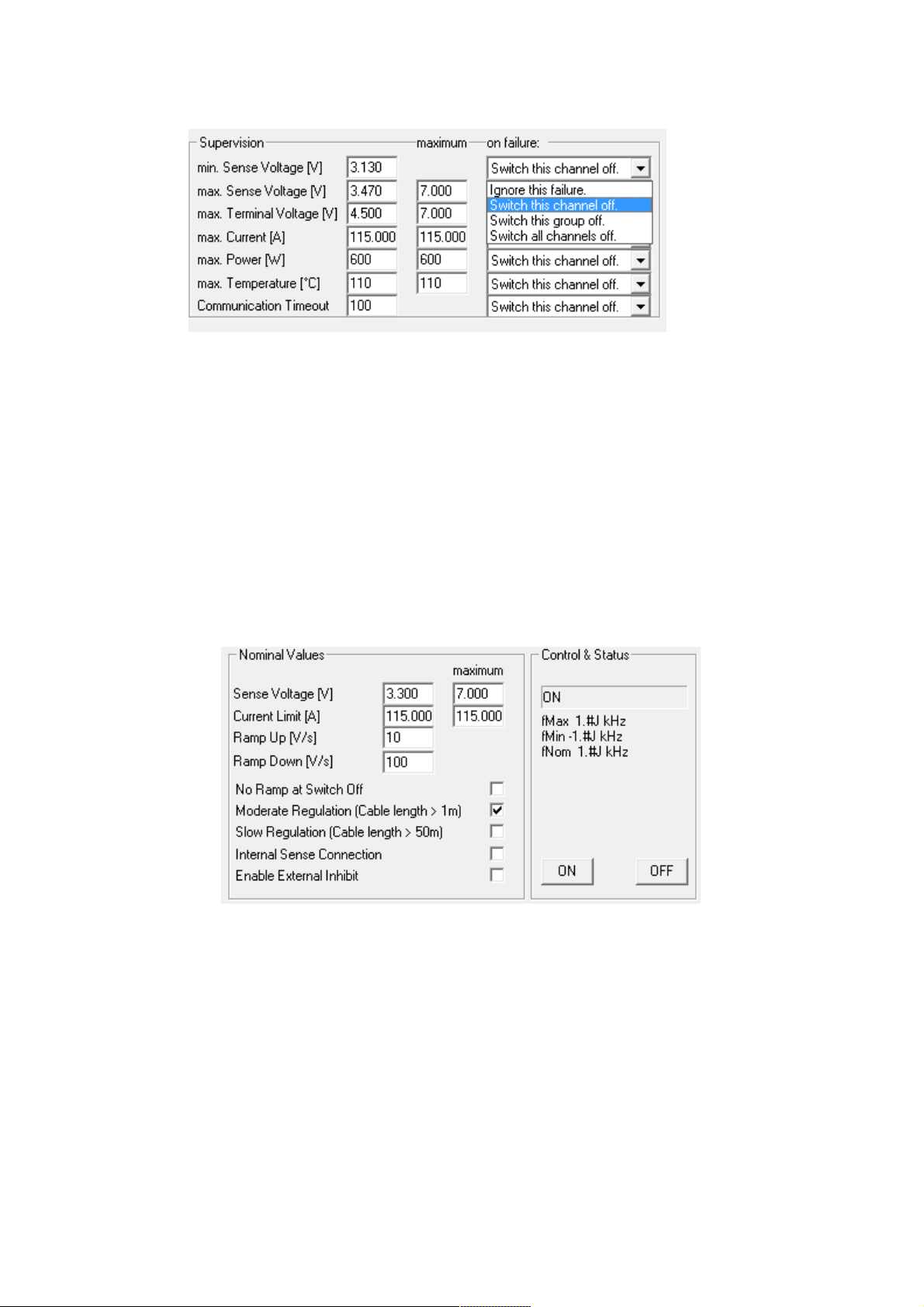
On the right hand side, “on failure:”, what would you like the PS to do if there is a supervision
problem: Ignore this failure, Switch channel off, etc
Nominal Values
Set the Sense Voltage[V]. It must be in range of the Supervision values entered previously.
Set the, “Current Limit [A]” as needed for your application.
See the *00679.A3 manual for more details regarding Ramp Up, Down, Regulation settings, etc.
Download the latest manual at: http://file.wiener-d.com/documentation/PL506-PL512/
28. May 2013 20 *00679.A4
Fig. 4.11: Supervision Problem
Fig. 4.12: Nominal Values
Page 26
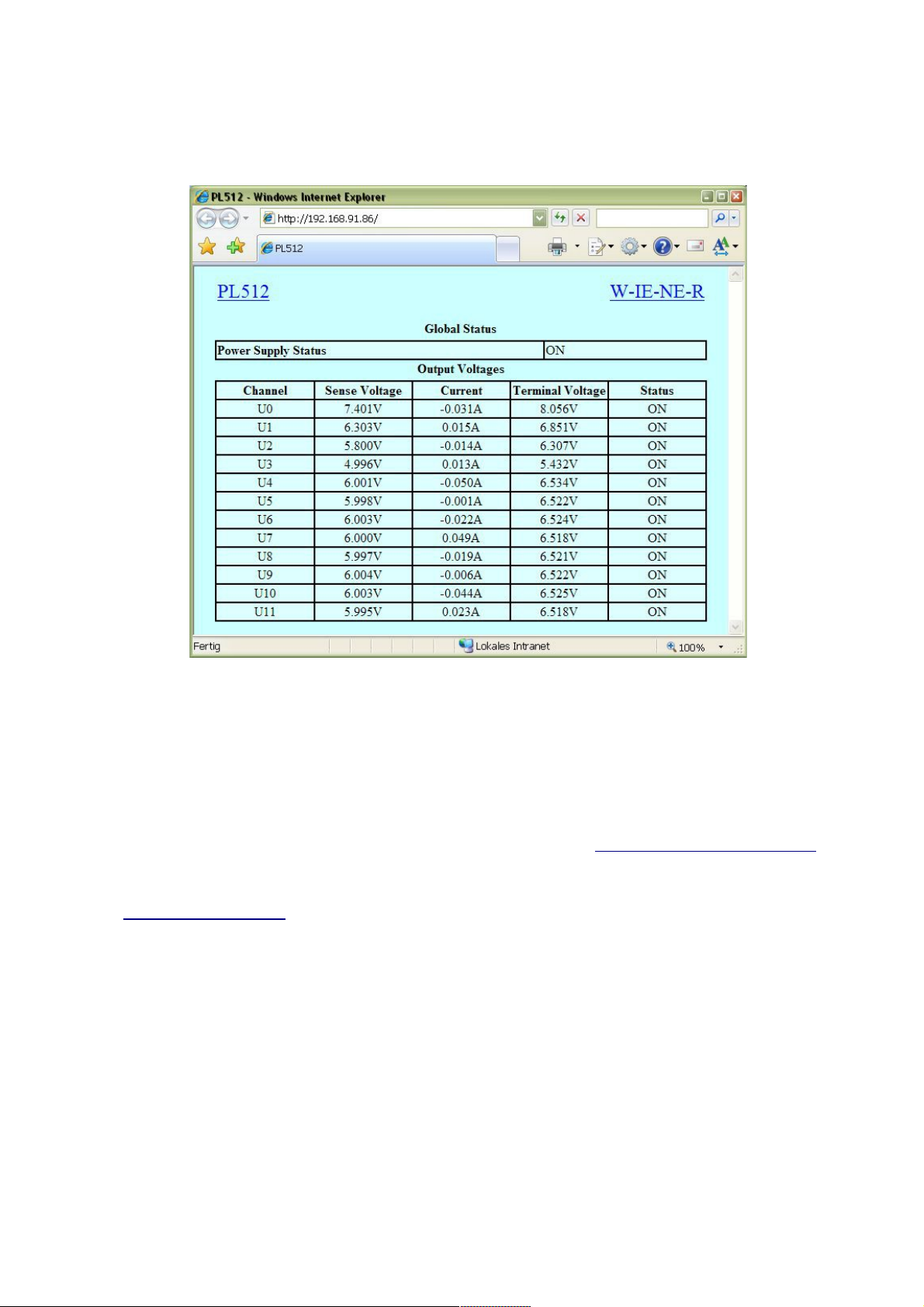
5 Web Server
The PL512/PL506 has a built-in web-server which allows the monitoring of the power supply with a
standard web browser.
6 SNMP Control
The SNMP (Simple Network Management Protocol) is generally used to monitor and control
computers and network routers. WIENER claimed a specific part of the SNMP name space and
implemented power supply specific items there. Protocol version 1 and 2c is implemented. The tree
view of the implemented items is appended in 8 SNMP OID Tree.
NetSNMP is an open source SNMP program which can be used to access the PL506/512 power
supply via the Simple Network Management Protocol. Please see http://net-snmp.sourceforge.net/
for more details.
Please install netSNMP from the CD-ROM or downloaded from the WIENER file server
http://file.wiener-d.com on the control computer. In order to perform SNMP calls from any
WIENER product the WIENER-CRATE-MIB file must be stored somewhere on the PC doing the
calls, by default that location should be /usr/share/snmp/mibs (Windows: C:\usr\share\snmp\mibs).
The most commonly used net-snmp calls are:
snmpwalk – returns groups of parameters / items
snmpget – returns a specific parameter (read)
snmpset – sets a specific parameter (write)
Please see the netSNMP description and help files for detailed instructions and options. All
parameters defined for WIENER crates and power supply systems are contained within the
WIENER-CRATE-MIB.txt file.
28. May 2013 21 *00679.A4
Page 27
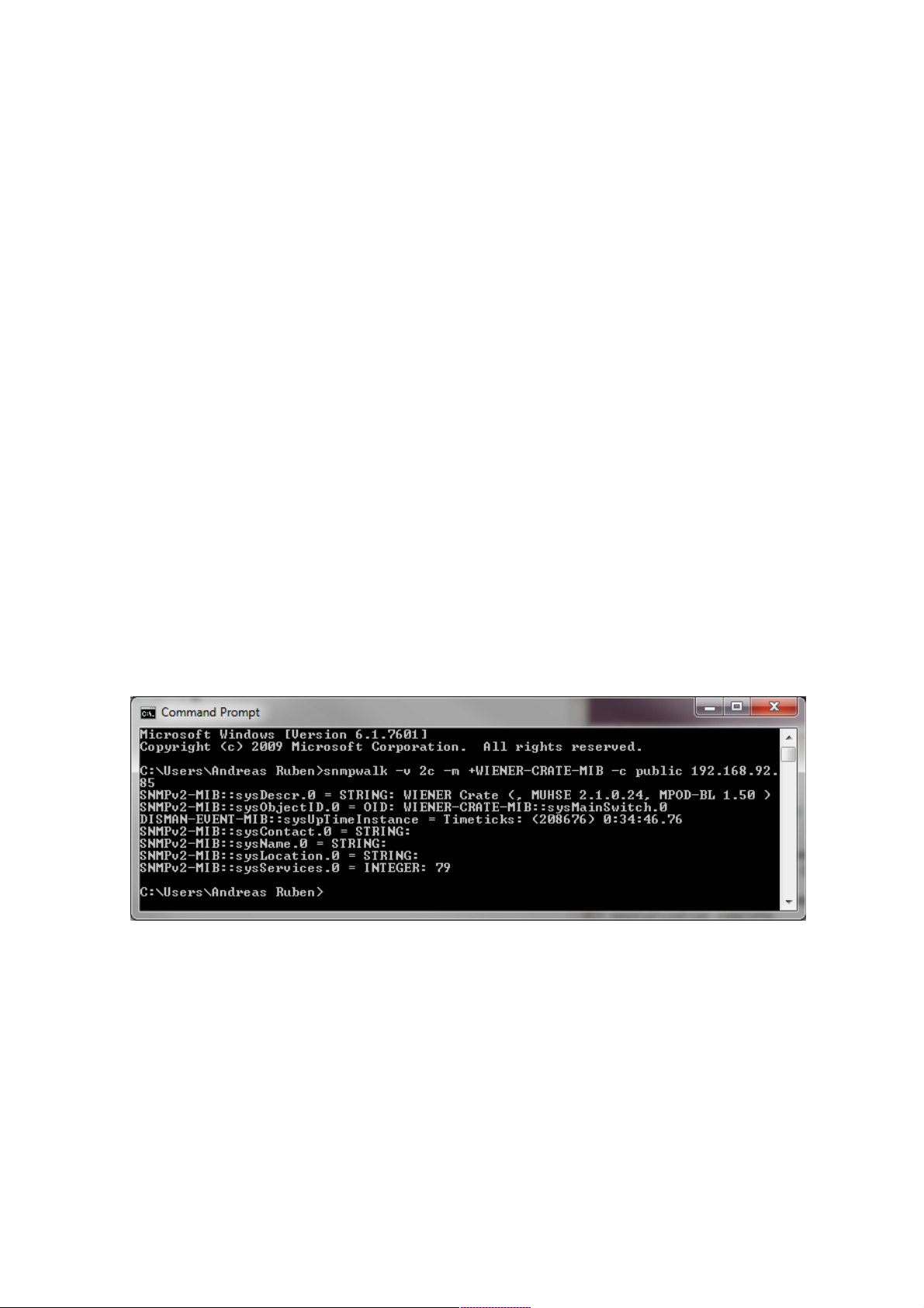
A fast an easy way to begin using SNMP is to use command line arguments. The command line
arguments specified in this document are based on netSNMP. The command line syntax is the same
for both windows and Linux (and probably MAC OSX).
A first communication with the PL506 or PL512 power supply can be done using the snmpwalk to
confirm the existence of the power supply at the given IP address. Please note that not all
commands/parameters are supported by WIENER VME/VXI crates and PL5xx or MPOD power
supplies.
snmpwalk -Cp -Oqv -v 2c -M $path -m +WIENER-CRATE-MIB -c public $ip
with:
snmpwalk: This command will retrieve a block of information.
-v 2c: This parameters specifies which version of the SNMP to use. WIENER devices use
SNMP 2C.
-M $path: This parameter should be replaced with the path to the WIENER-CRATEMIB.txt file. It is not needed in case the default path is used.
-m +WIENER-CRATE-MIB: This parameter tells the command to look at the WIENERCRATE-MIB to resolve the OID name.
-c public: This specifies which community of values can be accessed.
$ip: This should be replaced with the IP address of the PL506/512.
Example for PL506 system with IP address 192.168.92.85:
snmpwalk -v 2c -m +WIENER-CRATE-MIB -c public 192.168.92.85
returns:
SSNMPv2-MIB::sysDescr.0 = STRING: WIENER Crate (, MUHSE 2.1.0.24, MPOD-BL 1.50 )
SNMPv2-MIB::sysObjectID.0 = OID: WIENER-CRATE-MIB::sysMainSwitch.0
DISMAN-EVENT-MIB::sysUpTimeInstance = Timeticks: (208676) 0:34:46.76
SNMPv2-MIB::sysContact.0 = STRING:
SNMPv2-MIB::sysName.0 = STRING:
SNMPv2-MIB::sysLocation.0 = STRING:
SNMPv2-MIB::sysServices.0 = INTEGER: 79
A list of all available parameters or sub-parameters as for instance channels can be obtained using
the command snmpwalk with the parameter “crate”. To get all parameters use:
snmpwalk -Cp -Oqv -v 2c -M $path -m +WIENER-CRATE-MIB -c public $ip crate
example:
snmpwalk -v 2c -m +WIENER-CRATE-MIB -c public 192.168.92.85 crate
returns for a PL506 :
WIENER-CRATE-MIB::sysMainSwitch.0 = INTEGER: off(0)
28. May 2013 22 *00679.A4
Page 28

WIENER-CRATE-MIB::sysStatus.0 = BITS: 00
WIENER-CRATE-MIB::sysHardwareReset.0 = INTEGER: 0
WIENER-CRATE-MIB::outputNumber.0 = INTEGER: 6
WIENER-CRATE-MIB::outputIndex.u0 = INTEGER: u0(1)
WIENER-CRATE-MIB::outputIndex.u1 = INTEGER: u1(2)
WIENER-CRATE-MIB::outputIndex.u2 = INTEGER: u2(3)
WIENER-CRATE-MIB::outputIndex.u3 = INTEGER: u3(4)
WIENER-CRATE-MIB::outputIndex.u4 = INTEGER: u4(5)
WIENER-CRATE-MIB::outputIndex.u5 = INTEGER: u5(6)
WIENER-CRATE-MIB::outputName.u0 = STRING: U0
WIENER-CRATE-MIB::outputName.u1 = STRING: U1
WIENER-CRATE-MIB::outputName.u2 = STRING: U2
WIENER-CRATE-MIB::outputName.u3 = STRING: U3
WIENER-CRATE-MIB::outputName.u4 = STRING: U4
WIENER-CRATE-MIB::outputName.u5 = STRING: U5
WIENER-CRATE-MIB::outputGroup.u0 = INTEGER: 1
WIENER-CRATE-MIB::outputGroup.u1 = INTEGER: 2
WIENER-CRATE-MIB::outputGroup.u2 = INTEGER: 1
WIENER-CRATE-MIB::outputGroup.u3 = INTEGER: 2
WIENER-CRATE-MIB::outputGroup.u4 = INTEGER: 1
WIENER-CRATE-MIB::outputGroup.u5 = INTEGER: 2
WIENER-CRATE-MIB::outputStatus.u0 = BITS: 40 outputInhibit(1)
WIENER-CRATE-MIB::outputStatus.u1 = BITS: 40 outputInhibit(1)
WIENER-CRATE-MIB::outputStatus.u2 = BITS: 40 outputInhibit(1)
WIENER-CRATE-MIB::outputStatus.u3 = BITS: 40 outputInhibit(1)
WIENER-CRATE-MIB::outputStatus.u4 = BITS: 40 outputInhibit(1)
WIENER-CRATE-MIB::outputStatus.u5 = BITS: 40 outputInhibit(1)
WIENER-CRATE-MIB::outputMeasurementSenseVoltage.u0 = Opaque: Float: 0.000000 V
WIENER-CRATE-MIB::outputMeasurementSenseVoltage.u1 = Opaque: Float: 0.000000 V
WIENER-CRATE-MIB::outputMeasurementSenseVoltage.u2 = Opaque: Float: 0.000000 V
WIENER-CRATE-MIB::outputMeasurementSenseVoltage.u3 = Opaque: Float: 0.000000 V
WIENER-CRATE-MIB::outputMeasurementSenseVoltage.u4 = Opaque: Float: 0.000000 V
WIENER-CRATE-MIB::outputMeasurementSenseVoltage.u5 = Opaque: Float: 0.000000 V
WIENER-CRATE-MIB::outputMeasurementTerminalVoltage.u0 = Opaque: Float: 0.000000V
WIENER-CRATE-MIB::outputMeasurementTerminalVoltage.u1 = Opaque: Float: 0.000000V
WIENER-CRATE-MIB::outputMeasurementTerminalVoltage.u2 = Opaque: Float: 0.000000V
WIENER-CRATE-MIB::outputMeasurementTerminalVoltage.u3 = Opaque: Float: 0.000000V
WIENER-CRATE-MIB::outputMeasurementTerminalVoltage.u4 = Opaque: Float: 0.000000V
WIENER-CRATE-MIB::outputMeasurementTerminalVoltage.u5 = Opaque: Float: 0.000000V
WIENER-CRATE-MIB::outputMeasurementCurrent.u0 = Opaque: Float: 0.000000 A
WIENER-CRATE-MIB::outputMeasurementCurrent.u1 = Opaque: Float: 0.000000 A
WIENER-CRATE-MIB::outputMeasurementCurrent.u2 = Opaque: Float: 0.000000 A
WIENER-CRATE-MIB::outputMeasurementCurrent.u3 = Opaque: Float: 0.000000 A
WIENER-CRATE-MIB::outputMeasurementCurrent.u4 = Opaque: Float: 0.000000 A
WIENER-CRATE-MIB::outputMeasurementCurrent.u5 = Opaque: Float: 0.000000 A
WIENER-CRATE-MIB::outputMeasurementTemperature.u0 = INTEGER: 24
WIENER-CRATE-MIB::outputMeasurementTemperature.u1 = INTEGER: 25
WIENER-CRATE-MIB::outputMeasurementTemperature.u2 = INTEGER: 24
WIENER-CRATE-MIB::outputMeasurementTemperature.u3 = INTEGER: 26
WIENER-CRATE-MIB::outputMeasurementTemperature.u4 = INTEGER: 25
WIENER-CRATE-MIB::outputMeasurementTemperature.u5 = INTEGER: 29
WIENER-CRATE-MIB::outputSwitch.u0 = INTEGER: off(0)
WIENER-CRATE-MIB::outputSwitch.u1 = INTEGER: off(0)
WIENER-CRATE-MIB::outputSwitch.u2 = INTEGER: off(0)
WIENER-CRATE-MIB::outputSwitch.u3 = INTEGER: off(0)
WIENER-CRATE-MIB::outputSwitch.u4 = INTEGER: off(0)
WIENER-CRATE-MIB::outputSwitch.u5 = INTEGER: off(0)
WIENER-CRATE-MIB::outputVoltage.u0 = Opaque: Float: 3.299805 V
28. May 2013 23 *00679.A4
Page 29

WIENER-CRATE-MIB::outputVoltage.u1 = Opaque: Float: 24.000000 V
WIENER-CRATE-MIB::outputVoltage.u2 = Opaque: Float: 3.300293 V
WIENER-CRATE-MIB::outputVoltage.u3 = Opaque: Float: 24.000000 V
WIENER-CRATE-MIB::outputVoltage.u4 = Opaque: Float: 3.299805 V
WIENER-CRATE-MIB::outputVoltage.u5 = Opaque: Float: 24.000000 V
WIENER-CRATE-MIB::outputCurrent.u0 = Opaque: Float: 115.000000 A
WIENER-CRATE-MIB::outputCurrent.u1 = Opaque: Float: 23.000000 A
WIENER-CRATE-MIB::outputCurrent.u2 = Opaque: Float: 115.000000 A
WIENER-CRATE-MIB::outputCurrent.u3 = Opaque: Float: 23.000000 A
WIENER-CRATE-MIB::outputCurrent.u4 = Opaque: Float: 115.000000 A
WIENER-CRATE-MIB::outputCurrent.u5 = Opaque: Float: 23.000000 A
WIENER-CRATE-MIB::outputVoltageRiseRate.u0 = Opaque: Float: 100.000000 V/s
WIENER-CRATE-MIB::outputVoltageRiseRate.u1 = Opaque: Float: 100.000000 V/s
WIENER-CRATE-MIB::outputVoltageRiseRate.u2 = Opaque: Float: 100.000000 V/s
WIENER-CRATE-MIB::outputVoltageRiseRate.u3 = Opaque: Float: 100.000000 V/s
WIENER-CRATE-MIB::outputVoltageRiseRate.u4 = Opaque: Float: 100.000000 V/s
WIENER-CRATE-MIB::outputVoltageRiseRate.u5 = Opaque: Float: 100.000000 V/s
WIENER-CRATE-MIB::outputVoltageFallRate.u0 = Opaque: Float: 100.000000 V/s
WIENER-CRATE-MIB::outputVoltageFallRate.u1 = Opaque: Float: 100.000000 V/s
WIENER-CRATE-MIB::outputVoltageFallRate.u2 = Opaque: Float: 100.000000 V/s
WIENER-CRATE-MIB::outputVoltageFallRate.u3 = Opaque: Float: 100.000000 V/s
WIENER-CRATE-MIB::outputVoltageFallRate.u4 = Opaque: Float: 100.000000 V/s
WIENER-CRATE-MIB::outputVoltageFallRate.u5 = Opaque: Float: 100.000000 V/s
WIENER-CRATE-MIB::outputSupervisionBehavior.u0 = INTEGER: 17749
WIENER-CRATE-MIB::outputSupervisionBehavior.u1 = INTEGER: 17749
WIENER-CRATE-MIB::outputSupervisionBehavior.u2 = INTEGER: 17749
WIENER-CRATE-MIB::outputSupervisionBehavior.u3 = INTEGER: 17749
WIENER-CRATE-MIB::outputSupervisionBehavior.u4 = INTEGER: 17749
WIENER-CRATE-MIB::outputSupervisionBehavior.u5 = INTEGER: 17749
WIENER-CRATE-MIB::outputSupervisionMinSenseVoltage.u0 = Opaque: Float: 3.129883V
WIENER-CRATE-MIB::outputSupervisionMinSenseVoltage.u1 = Opaque: Float: 22.799805 V
WIENER-CRATE-MIB::outputSupervisionMinSenseVoltage.u2 = Opaque: Float: 3.129883V
WIENER-CRATE-MIB::outputSupervisionMinSenseVoltage.u3 = Opaque: Float: 22.799805 V
WIENER-CRATE-MIB::outputSupervisionMinSenseVoltage.u4 = Opaque: Float: 3.129883V
WIENER-CRATE-MIB::outputSupervisionMinSenseVoltage.u5 = Opaque: Float: 22.799805 V
WIENER-CRATE-MIB::outputSupervisionMaxSenseVoltage.u0 = Opaque: Float: 3.470215V
WIENER-CRATE-MIB::outputSupervisionMaxSenseVoltage.u1 = Opaque: Float: 25.200195 V
WIENER-CRATE-MIB::outputSupervisionMaxSenseVoltage.u2 = Opaque: Float: 3.470215V
WIENER-CRATE-MIB::outputSupervisionMaxSenseVoltage.u3 = Opaque: Float: 25.200195 V
WIENER-CRATE-MIB::outputSupervisionMaxSenseVoltage.u4 = Opaque: Float: 3.470215V
WIENER-CRATE-MIB::outputSupervisionMaxSenseVoltage.u5 = Opaque: Float: 25.200195 V
WIENER-CRATE-MIB::outputSupervisionMaxTerminalVoltage.u0 = Opaque: Float: 4.500000 V
WIENER-CRATE-MIB::outputSupervisionMaxTerminalVoltage.u1 = Opaque: Float: 27.000000 V
WIENER-CRATE-MIB::outputSupervisionMaxTerminalVoltage.u2 = Opaque: Float: 4.500000 V
WIENER-CRATE-MIB::outputSupervisionMaxTerminalVoltage.u3 = Opaque: Float: 27.000000 V
WIENER-CRATE-MIB::outputSupervisionMaxTerminalVoltage.u4 = Opaque: Float: 4.500000 V
WIENER-CRATE-MIB::outputSupervisionMaxTerminalVoltage.u5 = Opaque: Float: 27.000000 V
WIENER-CRATE-MIB::outputSupervisionMaxCurrent.u0 = Opaque: Float: 115.000000 A
WIENER-CRATE-MIB::outputSupervisionMaxCurrent.u1 = Opaque: Float: 23.000000 A
WIENER-CRATE-MIB::outputSupervisionMaxCurrent.u2 = Opaque: Float: 115.000000 A
WIENER-CRATE-MIB::outputSupervisionMaxCurrent.u3 = Opaque: Float: 23.000000 A
WIENER-CRATE-MIB::outputSupervisionMaxCurrent.u4 = Opaque: Float: 115.000000 A
WIENER-CRATE-MIB::outputSupervisionMaxCurrent.u5 = Opaque: Float: 23.000000 A
WIENER-CRATE-MIB::outputSupervisionMaxTemperature.u0 = INTEGER: 110 deg C
WIENER-CRATE-MIB::outputSupervisionMaxTemperature.u1 = INTEGER: 110 deg C
WIENER-CRATE-MIB::outputSupervisionMaxTemperature.u2 = INTEGER: 110 deg C
WIENER-CRATE-MIB::outputSupervisionMaxTemperature.u3 = INTEGER: 110 deg C
WIENER-CRATE-MIB::outputSupervisionMaxTemperature.u4 = INTEGER: 110 deg C
28. May 2013 24 *00679.A4
Page 30

WIENER-CRATE-MIB::outputSupervisionMaxTemperature.u5 = INTEGER: 110 deg C
WIENER-CRATE-MIB::outputConfigMaxSenseVoltage.u0 = Opaque: Float: 15.999512 V
WIENER-CRATE-MIB::outputConfigMaxSenseVoltage.u1 = Opaque: Float: 31.999023 V
WIENER-CRATE-MIB::outputConfigMaxSenseVoltage.u2 = Opaque: Float: 15.999512 V
WIENER-CRATE-MIB::outputConfigMaxSenseVoltage.u3 = Opaque: Float: 31.999023 V
WIENER-CRATE-MIB::outputConfigMaxSenseVoltage.u4 = Opaque: Float: 15.999512 V
WIENER-CRATE-MIB::outputConfigMaxSenseVoltage.u5 = Opaque: Float: 31.999023 V
WIENER-CRATE-MIB::outputConfigMaxTerminalVoltage.u0 = Opaque: Float: 15.999512 V
WIENER-CRATE-MIB::outputConfigMaxTerminalVoltage.u1 = Opaque: Float: 31.999023 V
WIENER-CRATE-MIB::outputConfigMaxTerminalVoltage.u2 = Opaque: Float: 15.999512 V
WIENER-CRATE-MIB::outputConfigMaxTerminalVoltage.u3 = Opaque: Float: 31.999023 V
WIENER-CRATE-MIB::outputConfigMaxTerminalVoltage.u4 = Opaque: Float: 15.999512 V
WIENER-CRATE-MIB::outputConfigMaxTerminalVoltage.u5 = Opaque: Float: 31.999023 V
WIENER-CRATE-MIB::outputConfigMaxCurrent.u0 = Opaque: Float: 255.992188 A
WIENER-CRATE-MIB::outputConfigMaxCurrent.u1 = Opaque: Float: 31.999023 A
WIENER-CRATE-MIB::outputConfigMaxCurrent.u2 = Opaque: Float: 255.992188 A
WIENER-CRATE-MIB::outputConfigMaxCurrent.u3 = Opaque: Float: 31.999023 A
WIENER-CRATE-MIB::outputConfigMaxCurrent.u4 = Opaque: Float: 255.992188 A
WIENER-CRATE-MIB::outputConfigMaxCurrent.u5 = Opaque: Float: 31.999023 A
WIENER-CRATE-MIB::outputSupervisionMaxPower.u0 = Opaque: Float: 600.000000 W
WIENER-CRATE-MIB::outputSupervisionMaxPower.u1 = Opaque: Float: 550.000000 W
WIENER-CRATE-MIB::outputSupervisionMaxPower.u2 = Opaque: Float: 600.000000 W
WIENER-CRATE-MIB::outputSupervisionMaxPower.u3 = Opaque: Float: 550.000000 W
WIENER-CRATE-MIB::outputSupervisionMaxPower.u4 = Opaque: Float: 600.000000 W
WIENER-CRATE-MIB::outputSupervisionMaxPower.u5 = Opaque: Float: 550.000000 W
WIENER-CRATE-MIB::outputRegulationMode.u0 = INTEGER: moderate(1)
WIENER-CRATE-MIB::outputRegulationMode.u1 = INTEGER: moderate(1)
WIENER-CRATE-MIB::outputRegulationMode.u2 = INTEGER: moderate(1)
WIENER-CRATE-MIB::outputRegulationMode.u3 = INTEGER: moderate(1)
WIENER-CRATE-MIB::outputRegulationMode.u4 = INTEGER: moderate(1)
WIENER-CRATE-MIB::outputRegulationMode.u5 = INTEGER: moderate(1)
WIENER-CRATE-MIB::outputConfigMaxTemperature.u0 = INTEGER: 110 deg C
WIENER-CRATE-MIB::outputConfigMaxTemperature.u1 = INTEGER: 110 deg C
WIENER-CRATE-MIB::outputConfigMaxTemperature.u2 = INTEGER: 110 deg C
WIENER-CRATE-MIB::outputConfigMaxTemperature.u3 = INTEGER: 110 deg C
WIENER-CRATE-MIB::outputConfigMaxTemperature.u4 = INTEGER: 110 deg C
WIENER-CRATE-MIB::outputConfigMaxTemperature.u5 = INTEGER: 110 deg C
WIENER-CRATE-MIB::groupsNumber.0 = INTEGER: 4
WIENER-CRATE-MIB::groupsIndex.0 = INTEGER: 0
WIENER-CRATE-MIB::groupsIndex.1 = INTEGER: 1
WIENER-CRATE-MIB::groupsIndex.2 = INTEGER: 2
WIENER-CRATE-MIB::groupsSwitch.0 = INTEGER: undefined(-1)
WIENER-CRATE-MIB::groupsSwitch.1 = INTEGER: undefined(-1)
WIENER-CRATE-MIB::groupsSwitch.2 = INTEGER: undefined(-1)
WIENER-CRATE-MIB::snmpCommunityName.public = STRING: "public"
WIENER-CRATE-MIB::snmpPort.0 = INTEGER: 161
WIENER-CRATE-MIB::firmwareUpdate.0 = ""
WIENER-CRATE-MIB::ipDynamicAddress.0 = IpAddress: 192.168.92.85
WIENER-CRATE-MIB::ipStaticAddress.0 = IpAddress: 192.168.92.85
WIENER-CRATE-MIB::macAddress.0 = Hex-STRING: 00 50 C2 2D CB D9
WIENER-CRATE-MIB::psSerialNumber.0 = STRING:
WIENER-CRATE-MIB::psOperatingTime.0 = INTEGER: 790593 s
WIENER-CRATE-MIB::psOperatingTime.0 = No more variables left in this MIB View (I
t is past the end of the MIB tree)
Further it is possible obtain the array of names or values for a specific parameter. The following
command provides a list of all existing output channels:
28. May 2013 25 *00679.A4
Page 31

snmpwalk -Cp -Oqv -v 2c -M $path -m +WIENER-CRATE-MIB -c public $ip outputName
Example:
snmpwalk -v 2c -m +WIENER-CRATE-MIB -c public 192.168.92.25 outputName
WIENER-CRATE-MIB::outputName.u0 = STRING: U0
WIENER-CRATE-MIB::outputName.u1 = STRING: U1
WIENER-CRATE-MIB::outputName.u2 = STRING: U2
WIENER-CRATE-MIB::outputName.u3 = STRING: U3
WIENER-CRATE-MIB::outputName.u4 = STRING: U4
WIENER-CRATE-MIB::outputName.u5 = STRING: U5
To see all output channel set voltage values use snmpwalk with outputVoltage:
snmpwalk -Cp -Oqv -v 2c -M $path -m +WIENER-CRATE-MIB -c public $ip outputVoltage
Example:
snmpwalk -v 2c -m +WIENER-CRATE-MIB -c public 192.168.2.25 outputVoltage
WIENER-CRATE-MIB::outputVoltage.u0 = Opaque: Float: 3.299805 V
WIENER-CRATE-MIB::outputVoltage.u1 = Opaque: Float: 24.000000 V
WIENER-CRATE-MIB::outputVoltage.u2 = Opaque: Float: 3.300293 V
WIENER-CRATE-MIB::outputVoltage.u3 = Opaque: Float: 24.000000 V
WIENER-CRATE-MIB::outputVoltage.u4 = Opaque: Float: 3.299805 V
WIENER-CRATE-MIB::outputVoltage.u5 = Opaque: Float: 24.000000 V
After obtaining information about the power supplies or a list of channels and parameters, it is useful
to be able to write or read information about it. This can be done using the snmpget and snmpset
commands.
snmpget -Oqv -v 2c -M $path -m +WIENER-CRATE-MIB -c guru $ip name.index
snmpset -v 2c -M $path -m +WIENER-CRATE-MIB -c guru $ip name.index format value
The most common kind of call you will want is to get data from the power supply. This is easily
done via the snmpget command. The example below retrieves information about whether the main
power for the crate is on. If you wish to test this example on your own system replace “$path” with
the path to WIENER-CRATE-MIB.txt (/usr/share/snmp/mibs by default and “$ip” with the ip
address of your MPOD (see following examples).
snmpget -v 2c -M $path -m +WIENER-CRATE-MIB -c public $ip sysMainSwitch.0
Example:
snmpget -v 2c -m +WIENER-CRATE-MIB -c public 192.168.92.85 sysMainSwitch.0
WIENER-CRATE-MIB::sysMainSwitch.0 = INTEGER: off(0)
This indicates that the crate or power supply is currently off. To better understand the call above we
will break it down by parameter:
snmpget: This command will retrieve a value from the PL506/512.
-v 2c: This parameters specifies which version of the SNMP to use. WIENER devices use
SNMP 2C.
-M $path: This parameter should be replaced with the path to the WIENER-CRATEMIB.txt file.
-m +WIENER-CRATE-MIB: This parameter tells the command to look at the WIENERCRATE-MIB to resolve the OID name.
-c public: This specifies which community of values can be accessed.
$ip: This should be replaced with the IP address of the PL506/512.
sysMainSwitch.0: This is the register you wish to retrieve.
Since we know from the call above that the power supply is off, we may want to turn it on. To turn
the PL506/512 on, we can use the command:
28. May 2013 26 *00679.A4
Page 32
snmpset -v 2c - path -m +WIENER-CRATE-MIB -c COMMUNITY $ip sysMainSwitch.0 i 1
Depending on the device type the community may be “public” for reading or “private” / “guru” for
write calls. In case the wrong community code is used a “not writable” error message will be
received.
Example:
snmpset -v 2c -m +WIENER-CRATE-MIB -c private 192.168.92.85 sysMainSwitch.0 i 1
WIENER-CRATE-MIB::sysMainSwitch.0 = INTEGER: on(1)
Most of the parameters for snmpset are the same as snmpget, the new parameters are highlighted
below.
i: Since sysMainSwitch.0 is an integer value, we specify the value to be an integer with.
1: This is the value we wish to write. In this case we write ‘one’ to set the main switch to on.
For most of the write commands (snmpset) the access type has to be changed from public to guru.
A complete list of value names that can be written or read via SNMP can be found in the WIENERCRATE-MIB file with detailed description but commonly needed values are:
Value Name Type Access Comments
outputVoltage Float R/W The Channel set Voltage
outputCurrent Float R/W The channel current limit
outputMeasurementSenseVoltage Float R Actual channel Voltage
mesaured at sense line
outputSwitch Integer R/W Turns channel ON/OFF
outputStatus Bits R Channel Status information
outputMeasurementTerminalVoltageFloat R Actual channel Voltage
measured at terminal
outputMeasurementCurrent Float R Actual channel current
outputMeasurementTemperature Integer R Temperature on power
module/channel
outputVoltageRiseRate Float R/W Channel ramp up rate
outputVoltageFallRate Float R/W Channel ramp down rate
outputRegulationMode Integer R/W Fast, moderate or slow
regulation
For example, to read channel set voltage use:
snmpget -Oqv -v 2c -M $path -m +WIENER-CRATE-MIB -c guru $ip outputVoltage.index
Example:
snmpget -v 2c -m +WIENER-CRATE-MIB -c public 192.168.92.85 outputVoltage.001
WIENER-CRATE-MIB::outputVoltage.u0 = Opaque: Float: 3.299805 V
Write and read individual set voltages, “guru” access needed to write!
snmpset -v 2c -m +WIENER-CRATE-MIB -c guru 192.168.92.85 outputVoltage.001 F 4.0
WIENER-CRATE-MIB::outputVoltage.u0 = Opaque: Float: 4.000000 V
Note the “F” before the 4.0, this indicates that the value is a floating point number.
The individual channels of PL506 and PL512 power supply can be turned on and off. To turn on
channel Ux:
snmpset -Oqv -v 2c -M $path -m +WIENER-CRATE-MIB -c guru $ip outputSwitch.index i 1
28. May 2013 27 *00679.A4
Page 33

The same channel can be turned off with:
snmpset -Oqv -v 2c -M $path -m +WIENER-CRATE-MIB -c guru $ip outputSwitch.index i 0
Example for switching on the first channel:
snmpset -v 2c -m +WIENER-CRATE-MIB -c guru 192.168.92.85 outputSwitch.u0 i 1
WIENER-CRATE-MIB::outputSwitch.u0 = INTEGER: on(1)
PL506 / 512 channels have programmable voltage ramp speeds for both up and down direction:
snmpset -Oqv -v 2c -M $path -m +WIENER-CRATE-MIB -c guru $ip
outputVoltageRiseRate.index F value
Example:
snmpset -v 2c -m +WIENER-CRATE-MIB -c guru 192.168.92.85 outputVoltageRiseRate.u0 F
10.0
WIENER-CRATE-MIB::outputVoltageRiseRate.u0 = Opaque: Float: 10.000000 V/s
snmpset -v 2c -m +WIENER-CRATE-MIB -c guru 192.168.92.85 outputVoltageFallRate.u0 F
100.0
WIENER-CRATE-MIB::outputVoltageFallRate.u0 = Opaque: Float: 100.000000 V/s
Change of community names / setting of passwords
For the communication with MPOD modules 4 types of SNMP communities are used,“public",
"private", "admin" and “guru” By default the community names are equal to the community types.
snmpwalk -v 2c -m +WIENER-CRATE-MIB -c admin 192.168.0.81 snmpCommunityName
WIENER-CRATE-MIB::snmpCommunityName.public = STRING: "public"
WIENER-CRATE-MIB::snmpCommunityName.private = STRING: "private"
WIENER-CRATE-MIB::snmpCommunityName.admin = STRING: "admin"
snmpwalk -v 2c -m +WIENER-CRATE-MIB -c private 192.168.0.81snmpCommunityName
WIENER-CRATE-MIB::snmpCommunityName.public = STRING: "public"
WIENER-CRATE-MIB::snmpCommunityName.private = STRING: "private"
In order to secure the MPOD system communication the community names can be used as
passwords and be changed accordingly. The following example shows how the change and test the
community names. Using a wrong community name will result in a time out error. Please note, that
especially the communities with write access (private, admin) should be protected.
snmpset -v 2c -m +WIENER-CRATE-MIB -c private 192.168.0.81 snmpCommunityName.private
s seCrET
WIENER-CRATE-MIB::snmpCommunityName.private = STRING: "seCrET"
snmpwalk -v 2c -m +WIENER-CRATE-MIB -c private 192.168.0.81snmpCommunityName
Timeout: No Response from 192.168.0.80
snmpwalk -v 2c -m +WIENER-CRATE-MIB -c seCrET 192.168.0.80 snmpCommunityName
WIENER-CRATE-MIB::snmpCommunityName.public = STRING: "public"
WIENER-CRATE-MIB::snmpCommunityName.private = STRING: ""seCrET"
WIENER-CRATE-MIB::snmpCommunityName.admin = STRING: "admin"
28. May 2013 28 *00679.A4
Page 34
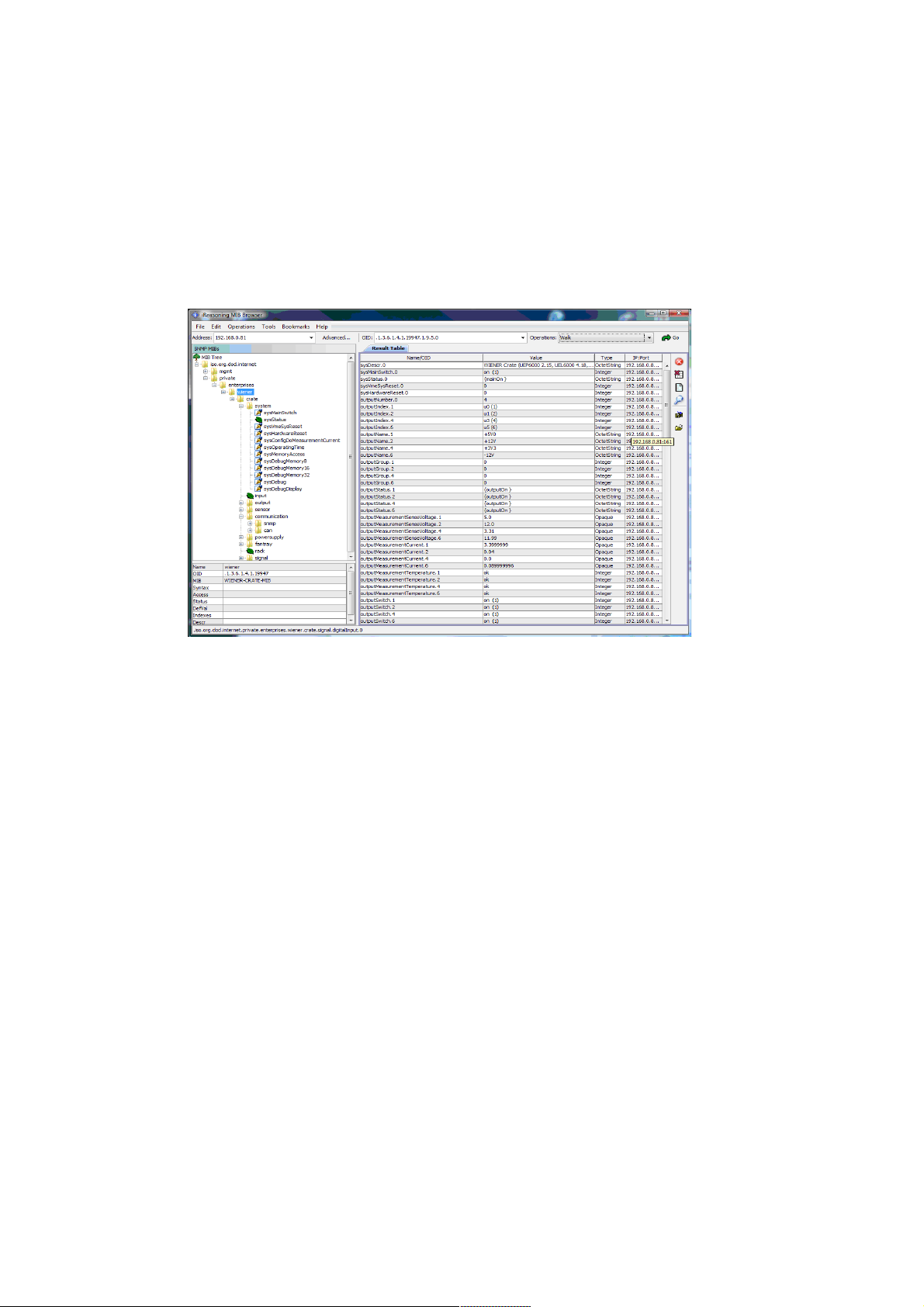
MIB Browser
There are several commercial or open source MIB-Browser programs available which can be used
for SNMP communication. These provide often a simple GUI and allow SNMP calls.
Following is a list of some free or open source MIB – browsers:
http://www.ireasoning.com/mibbrowser.shtml
http://www.serverscheck.com/mib_browser/
http://www.mibble.org/
http://www.ks-soft.net/hostmon.eng/mibbrowser/index.htm
http://www.tembria.com/products/snmpbrowser/index.html
28. May 2013 29 *00679.A4
Page 35

7 OPC Server
A server according to OPC Data Access V2.05 is optional available.
OPC (OLE for Process Control) allows fast and secure access to data and information under
Windows operating systems. As an industry-spanning, multi-vendor software interface, OPC
minimizes connection and maintenance overheads.
This server, running on a Computer with the Microsoft Windows XP operating system, enables
access to all controllers which are connected to the network (TCP/IP). It is possible to
● access from any OPC Client application to the data of one or more servers
● encapsulating the properties specific to the server and type of communication
● commissioning support due to automatic scanning of the network and registration of
communication stations
● restricting access rights by the underlying Microsoft DCOM.
The details of the OPC server can be found in the manual delivered with the OPC server software.
28. May 2013 30 *00679.A4
Page 36
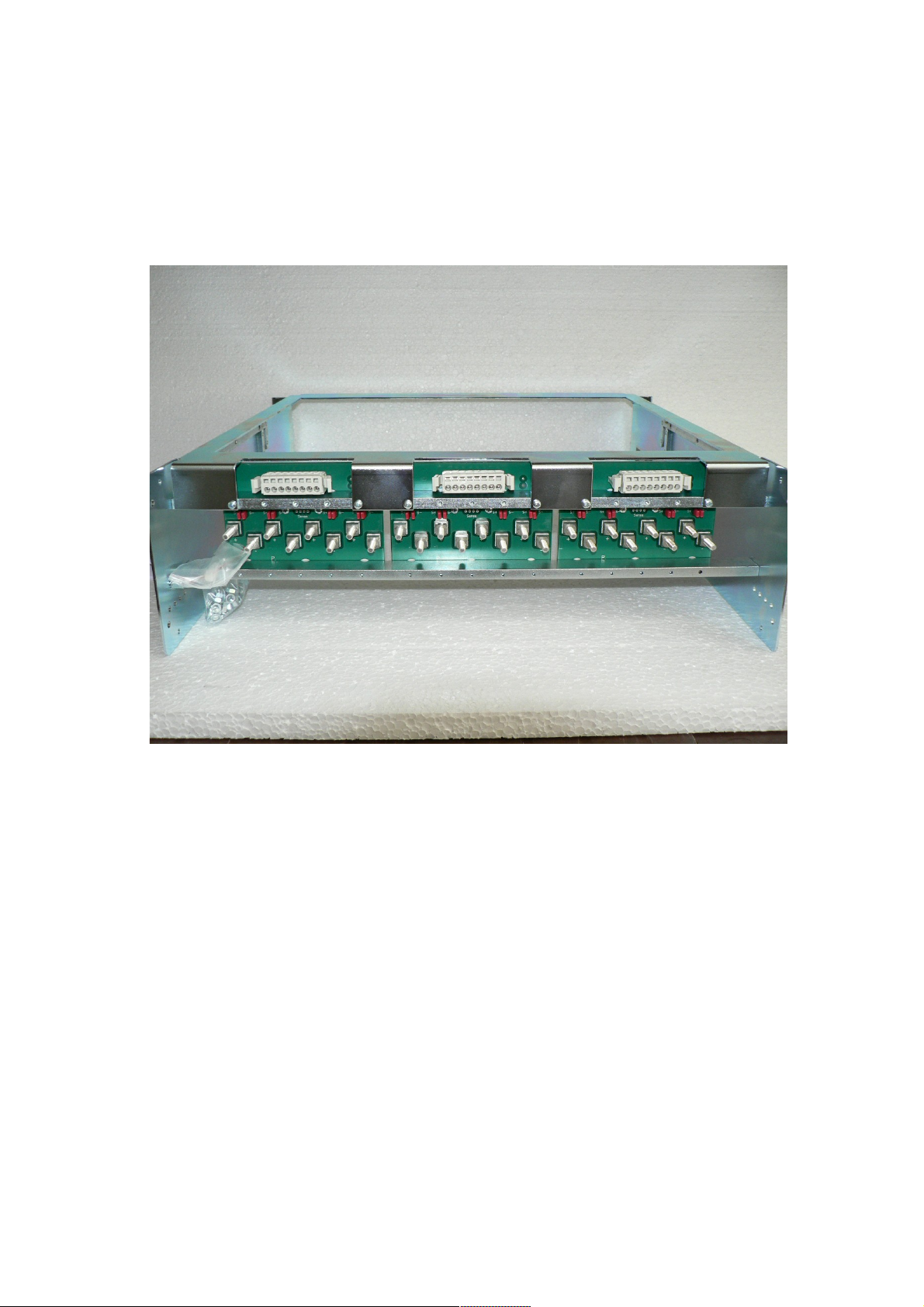
8 Power Bins PBN506/PBN512
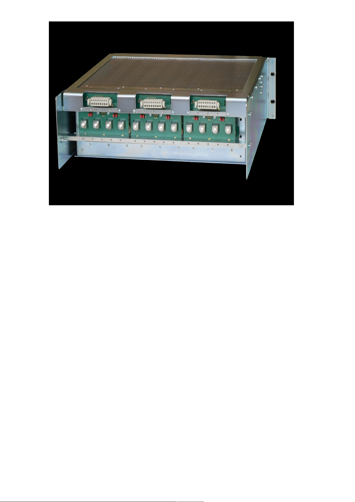
For easy exchange of the PL512/PL506 Power Box the special bins PBN506/PBN512 are provided:
The low voltage/high current cabling is connected to M5 threaded bolts (MULTICONTACT). The
arrangement is the same as at the power box: Starting from left with U0, and positive outputs up –
negative outputs down.
Each sense lines of four output channels are connected to an eightfold pluggable terminal row.
If remote sensing is not used, the sense lines can be connected to the power outputs with jumpers.
28. May 2013 31 *00679.A4
Figure 8.1: PBN512 -3U RATO Power Bin
Page 37
28. May 2013 32 *00679.A4
Figure 8.2: PBN506 -3U RASO Power Bin (with PL506 Power Supply inserted)
Page 38

Appendix A: Data Sheet
Rated Input Voltage: 106 – 230 V AC, +/- 15% variation allowed
Rated Input Current: 16 A
Sinusoidal: CE EN 60555, IEC 555 pow. fact. 0,98 (230VAC)
50/60 Hz
Inrush current: 16 A, cold unit
Output Insulation (SELV) CE EN 60950 , ISO 380, VDE 0805, UL 1950, C22.2.950
DC Output power with different input voltages at the rated current (16A), calculated with typical
efficiency of 75%
115VAC / 1.380Wnom, 1580Wpeak 230VAC / 2.760W, 3170Wpeak
Regulation fast remote sense circuit (short sensed distance, sense connected to output at the
PBN506/PBN512 power bin):
Static: MDC/M 2-8 V / 30–60 V < 15 mV (+/-100% load, +/- full mains
range)
MDC/M other voltages < 0.05 % (+/-100% load, +/- full DC
input range)
Dynamic (0.5 m wire): MDC/M 2-8 V < 100 mV (50 % - 75 % load change)
other < 0.7 % (50 % - 75 % load change)
Recovery Time: MDC/M 2-8V 1%: 0.2 ms
0.1%: 0.5 ms
(50 % - 75 % load change)
MDC/M 5-16V, 7-24V 1%: 0.0 ms
0.1%: 1.0 ms
(50 % - 75 % load change)
MDC/M 30-60V 1%: 0.5 ms
0.1%: 1.0 ms
(50 % - 75 % load change)
Conditions Current slope <1000A/ms, 20mF per 100A parallel to load
Regulation slow remote sense circuit (long sensed distance):
Static: MDC/M 2-8V/ 30-60V < 15 mV (+/-100% load, +/- full mains
range)
Other < 0.05 % (+/-100% load, +/- full mains
range)
Dynamic:
Dynamic deviation depends on current slope resp. filter capacitors at load
side only
30m cable to load, 0,3mF capacitance at load side, 1V drop at nominal
load, 10% - 90 % load change with 3ms slope (50A output= 13,33A/ms)
leads to less than 10% temporary output voltage deviation
Recovery Time (40m
wire, 5V at load side,
U
drop
< 2 V:
MDC 2-7V, 2-8V 10%: <15 ms
1%: <25 ms
(50 % - 75 % load change)
Other 10%: <15 ms
1%: < 33 ms
(50 % - 75 % load change)
28. May 2013 33 *00679.A4
Page 39

DC Output Characteristics:
Sense compensation
range:
Limited to < 10V or nominal voltage (whichever is lower).
Regulation mode: The voltage at the sense connection point is regulated.
Floating range: 500 V test voltage
Noise and ripple: Voltage < 8 V
Voltage > 8 V
< 10 mV
PP
< 15 mV
PP
(0.5 m wire, 0–20 MHz)
< 3 mV
PP
< 1.5 mV
RMS
(10 m wire, 0-300 MHz)
Conditions at the load: Parallel (X) 330µF and 1µF ceramic, 100nF HF- conducting to case (Y)
each line
Emission: CE EN 50081-1 (EN 55 022-B)
Immunity: CE EN 50082-1 or 2
Operating
temperature:
10 °C – 40 °C
Storage Temperature: - 30 °C - + 85 °C (cooling water must be completely removed, else +3 °C
- +85 °C)
Temp.- Coefficient: < 0.2% / 10K
Stability (constant
conditions)
<5mV or 0.1% within 24 h, <25mV or 0.3% within 6 months
Current limiting: Programmable
Status control / DC
Off (trip off):
Tripping global, group- or channel wise programmable (after overload,
overheat , overvoltage, undervoltage)
Interlock input: optional
Efficiency (per
Module):
65% 2V/ -81% >5V/ -85% >7V -87% >12V/ -90% >48V at nominal
input voltage
M T B F, cooled by:
Water, 30°C inflow:
Forced Air, 30°C
entrance:
Conditions: 3kW DC output with 80% efficiency (600W internal power
dissipation: WORST CASE)
ca. 120,000 h , put through > 50l/h for <10°C DT of cooling water.
Minimum differential pressure >0.5 bar, abs. max. pressure <15 bar
ca. 90,000 h , put through > 153m3/h for <15°C DT of cooling air,
ambient air pressure 1 bar. Adequate airflow is roughly 1,4m/s.
Values for air cooled units are valid for new ones. Abrasive dust,
corrosion, etc. can limiting the heat transfer to the cooling air during
lifetime. Higher operating temperature is the consequence.
Increasing of internal temperature at the most critical points of 10°C will
reduce the MTBF by 50% Lower operating temperatures will increase the
MTBF accordingly, independent of cooling medium.
Communication Ethernet 10/100M, USB 2
28. May 2013 34 *00679.A4
Page 40

Measurement Accuracy (typical values)
Voltage ± 0.1% of the maximum output voltage of the channel
Current MDC (single module) ± 1%
MDC (paralleled) ± 1%
MDH ± 1 %
Construction
features, Accessories:
3 U box with extraction lever:
max. 6 modules, up to 3 kW / 3,6kW
output power
Connections / plugs: 24 female pins 80A, parallel used for
higher currents, 3 x 9pin Sub D for
sensing (each for 4 channels)
Dimensions (w, h, d) 434 mm x 132 mm x 325 mm
Weight: 31,5 kg
Accessories: 19" Power Bins PBN506/PBN512 for plug in PL506/PL512 power
supplies power contacts with threated bolts and sense terminals at rear
side.
Types
PBN506 -4U
PBN512 -4U :
4U x 450mm mounting depth, 1 U air
baffle, strain relief, cooling air entry frontor bottom side, for 3U – Box
Special power bins / 19'' assembly with 3U and 6U (for two
PL506/PL512 boxes) available. 450mm mounting depth
28. May 2013 35 *00679.A4
Page 41
Appendix B: Ordering Information
Standard 0P11.xxxx
Special versions for CERN 0M11.xxxx
The left side of the ordering number is not descriptive, it is randomly assigned to the requested
module & options configuration. Up to six power modules may be used inside of one power box.
The following modules are possible (external ventilation necessary):
Module Type Channels per
Module
Optimal Voltage
Range
Peak Output
Current
Continuous
Output Power
MDC 2 2V ... 7V/8V 2*55A 2*300W
MDC 2 5/7V ... 15/16V 2*22A 2*300W
MDC 2 7V ... 24 V 2*11.5A 2*250W
MDC 2 30V ... 60V 2*6.6A 2*300W
The following modules can be used without external ventilation (integrated fans):
Module Type Channels per
Module
Optimal Voltage
Range
Peak Output
Current
Continuous
Output Power
MDH 2 2V ... 7V/8V 2*30A 2*210W
MDH 2 5/7V ... 15/16V 2*20A 2*250W
MDH 2 7V...24V 11.5A 2*275W
MEH 1 2...7V 115A 550W
MEH 1 6...10V 80A 550W
MEH 1 7...16V 46A 550W
MEH 1 12...30V 23A 550W
MEH 1 30...60V 13.5A 550W
All power modules can be ordered with different sense regulation characteristics:
● Fast Fastest regulation, but may be instable if connected to cables longer
than 1 m.
● Moderate This is the standard configuration for cable length up to 30 m
● Slow This is used for much longer cables
Available Power Bins:
Ordering Number
Power Bin (MARA) 3U 0B15.1200
Power Bin (MARA) 6U, for two power boxes 0B14.2400
28. May 2013 36 *00679.A4
Page 42

Appendix C: SNMP OID Tree
Only a small part of general SNMP OIDs is implemented. This is the tree view:
+--iso(1)
|
+--org(3)
|
+--dod(6)
|
+--internet(1)
|
+--directory(1)
|
+--mgmt(2)
| |
| +--mib-2(1)
| |
| +--system(1)
| | |
| | +-- -R-- String sysDescr(1)
| | | Textual Convention: DisplayString
| | | Size: 0..255
| | +-- -R-- ObjID sysObjectID(2)
| | +-- -R-- TimeTicks sysUpTime(3)
| | +-- -RW- String sysContact(4)
| | | Textual Convention: DisplayString
| | | Size: 0..255
| | +-- -RW- String sysName(5)
| | | Textual Convention: DisplayString
| | | Size: 0..255
| | +-- -RW- String sysLocation(6)
| | | Textual Convention: DisplayString
| | | Size: 0..255
| | +-- -R-- INTEGER sysServices(7)
| | | Range: 0..127
This is the tree view of the wiener-specific SNMP namespace. It could be generated with the
command „snmptranslate -w 80 -Tp WIENER-CRATE-MIB::wiener“. Because it's a general
definition, usable for different types of crates, some items may be not implemented in the real
hardware. Here the not relevant parts are omitted.
The wiener OID is located at iso(1).org(3).dod(6).internet(1).private(4).enterprises(1).
A detailed description of the SNMP functionality can be found in the corresponding MIB file
(WIENER-CRATE-MIB.txt)
+--crate(1)
|
+--system(1)
| |
| +-- -RW- EnumVal sysMainSwitch(1)
| | Values: OFF(0), ON(1)
| +-- -R-- BitString sysStatus(2)
| | Values: mainOn(0), mainInhibit(1), localControlOnly(2),
| | inputFailure(3), outputFailure(4), fantrayFailure(5),
| | sensorFailure(6), VmeSysfail(7),
| | plugAndPlayIncompatible(8)
| +-- -RW- EnumVal sysVmeSysReset(3)
| Values: TRIGGER(1)
|
+--input(2)
|
+--output(3)
| |
| +-- -R-- INTEGER outputNumber(1)
| | Range: 0..255
| |
| +--outputTable(2)
| | |
| | +--outputEntry(1)
| | | Index: outputIndex
| | |
| | +-- ---- EnumVal outputIndex(1)
| | | Values: U0(1), U1(2), U2(3), U3(4), U4(5), U5(6), U6(7),
| | | U7(8), U8(9), U9(10), U10(11), U11(12)
| | +-- -R-- String outputName(2)
28. May 2013 37 *00679.A4
Page 43

| | | Textual Convention: DisplayString
| | | Size: 1..4
| | +-- -RW- INTEGER outputGroup(3)
| | | Range: 0..127
| | +-- -R-- BitString outputStatus(4)
| | | Values: outputOn(0), outputInhibit(1),
| | | outputFailureMinSenseVoltage(2),
| | | outputFailureMaxSenseVoltage(3),
| | | outputFailureMaxTerminalVoltage(4),
| | | outputFailureMaxCurrent(5),
| | | outputFailureMaxTemperature(6),
| | | outputFailureMaxPower(7),
| | | outputFailureTimeout(9),
| | | outputCurrentLimited(10), outputRampUp(11),
| | | outputRampDown(12)
| | +-- -R-- Opaque outputMeasurementSenseVoltage(5)
| | | Textual Convention: Float
| | | Size: 7
| | +-- -R-- Opaque outputMeasurementTerminalVoltage(6)
| | | Textual Convention: Float
| | | Size: 7
| | +-- -R-- Opaque outputMeasurementCurrent(7)
| | | Textual Convention: Float
| | | Size: 7
| | +-- -R-- EnumVal outputMeasurementTemperature(8)
| | | Values: OK(-128), FAILURE(127)
| | +-- -RW- EnumVal outputSwitch(9)
| | | Values: OFF(0), ON(1)
| | +-- -RW- Opaque outputVoltage(10)
| | | Textual Convention: Float
| | | Size: 7
| | +-- -RW- INTEGER outputAdjustVoltage(11)
| | | Range: -128..127
| | +-- -RW- Opaque outputCurrent(12)
| | | Textual Convention: Float
| | | Size: 7
| | +-- -RW- INTEGER outputSupervisionBehavior(15)
| | | Range: 0..65535
| | +-- -RW- Opaque outputSupervisionMinSenseVoltage(16)
| | | Textual Convention: Float
| | | Size: 7
| | +-- -RW- Opaque outputSupervisionMaxSenseVoltage(17)
| | | Textual Convention: Float
| | | Size: 7
| | +-- -RW- Opaque outputSupervisionMaxTerminalVoltage(18)
| | | Textual Convention: Float
| | | Size: 7
| | +-- -RW- Opaque outputSupervisionMaxCurrent(19)
| | | Textual Convention: Float
| | | Size: 7
| | +-- -RW- Opaque outputConfigMaxSenseVoltage(21)
| | | Textual Convention: Float
| | | Size: 7
| | +-- -RW- Opaque outputConfigMaxTerminalVoltage(22)
| | | Textual Convention: Float
| | | Size: 7
| | +-- -RW- Opaque outputConfigMaxCurrent(23)
| | | Textual Convention: Float
| | | Size: 7
| | +-- -RW- Opaque outputSupervisionMaxPower(24)
| | Textual Convention: Float
| | Size: 7
| |
| +-- -R-- INTEGER groupsNumber(3)
| | Range: 1..255
| |
| +--groupsTable(4)
| |
| +--groupsEntry(1)
| | Index: groupsIndex
| |
| +-- ---- EnumVal groupsIndex(1)
| | Values: ALL(0)
| +-- --W- EnumVal groupsSwitch(9)
| Values: UNDEFINED(-1), OFF(0), ON(1)
|
+--communication(5)
| |
| +--snmp(1)
| |
| +--snmpCommunityTable(1)
28. May 2013 38 *00679.A4
Page 44

| | |
| | +--snmpCommunityEntry(1)
| | | Index: snmpAccessRight
| | |
| | +-- ---- EnumVal snmpAccessRight(1)
| | | Values: public(1), private(2), admin(3), guru(4)
| | +-- -RW- String snmpCommunityName(2)
| | Size: 0..14
| |
| +-- -RW- INTEGER snmpPort(2)
|
+--powersupply(6)
| |
| +-- -R-- String psSerialNumber(2)
| | Textual Convention: DisplayString
| | Size: 0..255
| +-- -R-- INTEGER psOperatingTime(3)
| +-- -RW- String psDirectAccess(1024)
| Size: 1..14
|
28. May 2013 39 *00679.A4
Page 45
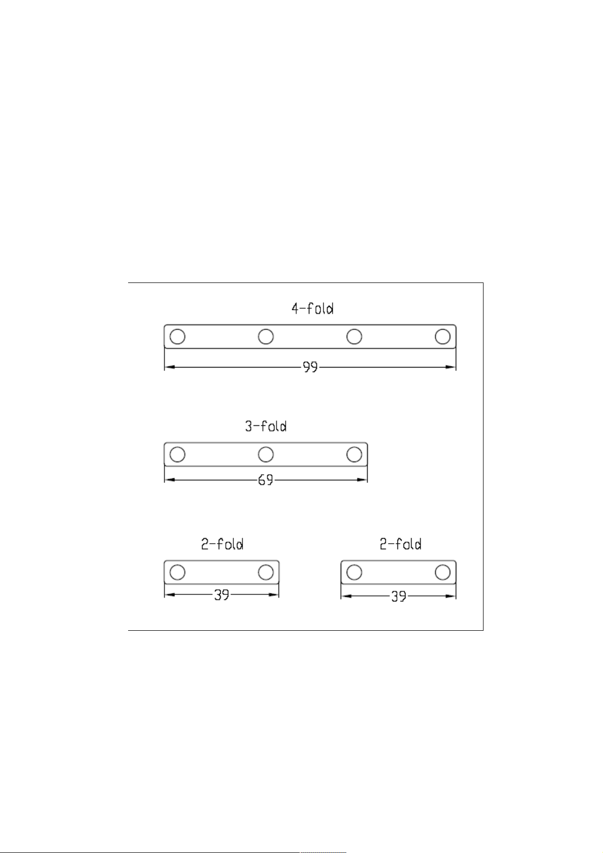
Appendix D: Parallel Connection of Output Channels
A set of six current bars ( 4-fold ) will be delivered by each power bin in a
companion-assembly-pack.
How to use the current bars
If the power supply has channels with more than one contact pair, use the current bars to connect
each option. For best operation it is necessary to connect the parallel outputs together as near as
possible at the power supply site. For 200A (4-fold) the current bars can be used as they are, for 3fold or dual paralleling they have to be cut accordingly.
4-fold : 200A ( order number : 1480753.A1 )
3-fold : 150A
2-fold : 100A
28. May 2013 40 *00679.A4
Figure 8.3: Current Bar Dimensions
Page 46
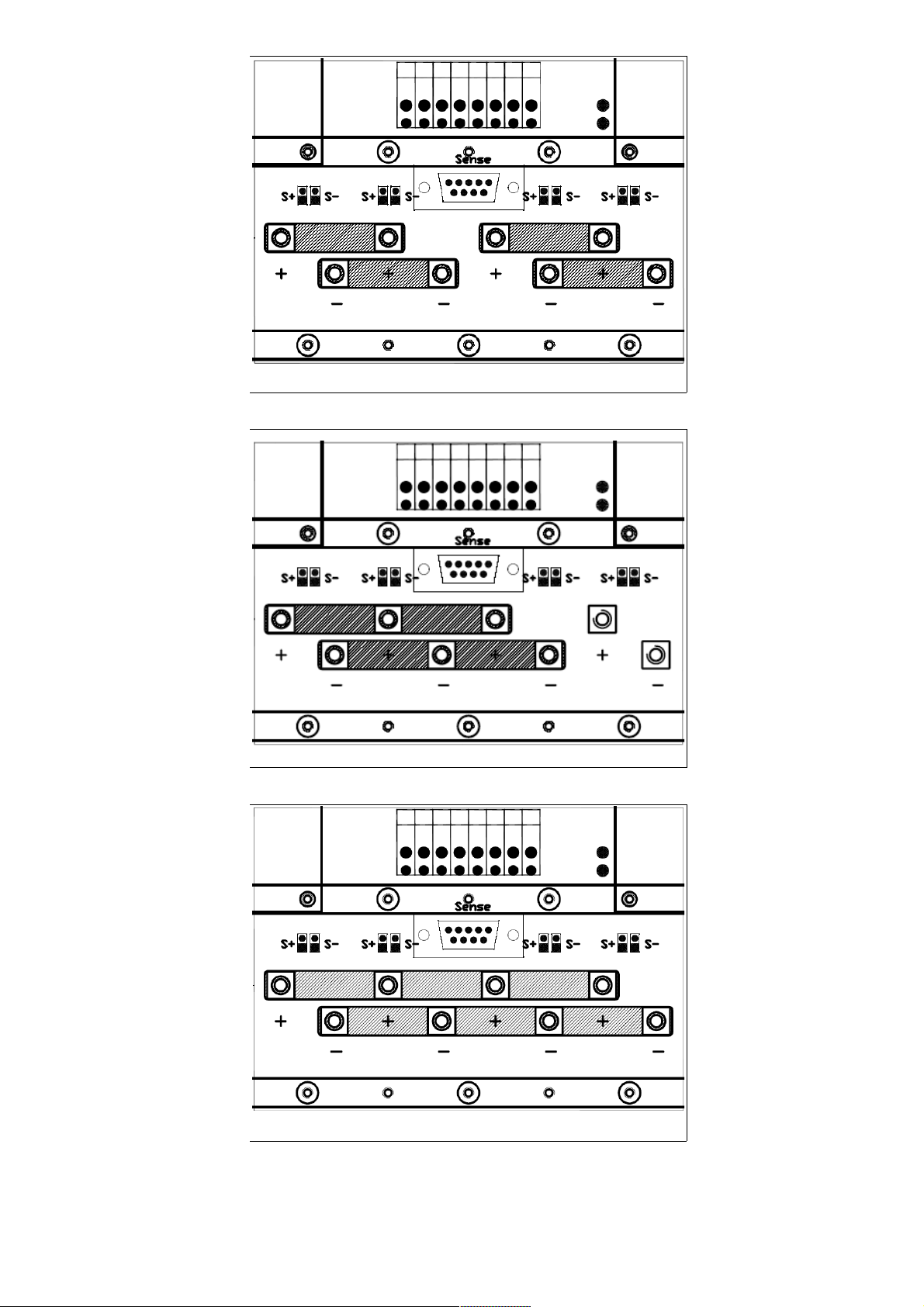
28. May 2013 41 *00679.A4
Figure 8.4: Two Channels Parallel
Figure 8.5: Three Channels Parallel
Figure 8.6: Four Channels Parallel
 Loading...