

Page 1

MicroLink system
User’s instructions
for
MicroLink MLX FM receiver
HandyMic TX3 FM transmitter
MicroVox TX2 FM transmitter
Page 2

Contents
Introduction· · · · · · · · · · · · · · · · · · · · · · · · · · · · · · 3
The FM system and how it works · · · · · · · · · · · · · · · · · 6
TheMicroLinkreceiver · · · · · · · · · · · · · · · · · · · · · · · 8
How the MicroLink works · · · · · · · · · · · · · · · · · · · · · 8
Description · · · · · · · · · · · · · · · · · · · · · · · · · · · · · 9
Attaching and removing the MicroLink · · · · · · · · · · · · · 11
Operating the MicroLink receiver · · · · · · · · · · · · · · · · 13
TheHandyMictransmitter · · · · · · · · · · · · · · · · · · · · 15
How the HandyMic works · · · · · · · · · · · · · · · · · · · · 15
Description · · · · · · · · · · · · · · · · · · · · · · · · · · · · 17
HandyMic accessories · · · · · · · · · · · · · · · · · · · · · · 19
Microphone switch modes · · · · · · · · · · · · · · · · · · · · 20
Instructions for use of the HandyMic · · · · · · · · · · · · · · 22
1.Thecompaniontechnique · · · · · · · · · · · · · · · · · · · 23
2.The interviewtechnique · · · · · · · · · · · · · · · · · · · · 25
3.The lecturetechnique · · · · · · · · · · · · · · · · · · · · · 26
4.The audio-visualtechnique · · · · · · · · · · · · · · · · · · 27
Recharging the HandyMic · · · · · · · · · · · · · · · · · · · · 30
TheMicroVoxTransmitter · · · · · · · · · · · · · · · · · · · · 32
How the MicroVox works· · · · · · · · · · · · · · · · · · · · · 32
Description · · · · · · · · · · · · · · · · · · · · · · · · · · · · 34
MicroVox accessories · · · · · · · · · · · · · · · · · · · · · · · 36
Connecting the microphone · · · · · · · · · · · · · · · · · · · 38
The battery · · · · · · · · · · · · · · · · · · · · · · · · · · · · 39
Inserting the battery · · · · · · · · · · · · · · · · · · · · · · · 41
How to switch on the MicroVox · · · · · · · · · · · · · · · · · 42
Connecting audio-visuals · · · · · · · · · · · · · · · · · · · · 43
GettingStarted · · · · · · · · · · · · · · · · · · · · · · · · · · · 44
Operating Range · · · · · · · · · · · · · · · · · · · · · · · · · 44
Maintenance · · · · · · · · · · · · · · · · · · · · · · · · · · · · · 46
Daily maintenance · · · · · · · · · · · · · · · · · · · · · · · · 46
Troubleshooting· · · · · · · · · · · · · · · · · · · · · · · · · · 49
Warranty · · · · · · · · · · · · · · · · · · · · · · · · · · · · · · · 55
Notes · · · · · · · · · · · · · · · · · · · · · · · · · · · · · · · 55
2
Page 3

Introduction
At Widex, our overall mission is to give people
with a hearing loss the same opportunities for
communication as people with normal hearing. A
Widex hearing aid, combined with the MicroLink,
goes a long way towards achieving this goal by
ensuring optimal listening comfort and speech
understanding. In difficult listening situations, in
particular, the MicroLink gives people with a
hearing loss new possibilities.
In order to get the full benefit of your MicroLink
FM system, please read these instructions care
fully. They contain a description of all parts of the
system as well as a section on maintenance and
troubleshooting.
-
3
Page 4

TheMicroLink system isbasedon technology that
makes it possible to manufacture an FM radio
receiver so tiny that it can be connected to a hear
ing aid. The receiver’s power consumption is very
low, so it can be powered by the hearing aid’s own
battery.
The MicroLink FM system effectively overcomes
the three fundamental obstacles to optimum com
munication: distance, noise and echo and – espe
cially – the combination of these factors. The
system is completely cordless and therefore very
easy to use.
Now you can concentrate on the message behind
what is being said, rather than using your energy
-
-
-
on trying to make out the words. Practically
speaking,with your MicroLinkyour ears areright
next to the FM transmitter. This creates an opti
mum listening situation with maximum signal
strength and a minimum of noise and echo.
-
4
Page 5

If used and cared for properly, your MicroLink
system – used in combination with your Widex
hearing aid – will give you many pleasurable lis
tening opportunities. The MicroLink system is a
precision instrument that can be damaged if
knocked or bumped. Therefore it should be hand
led with care and we recommend that you keep it
in the leather case when you do not use it.
-
-
5
Page 6

The FM system and how it works
An FM system is a radio system in which signals
are sent via radio waves from the transmitter to
the receiver. “FM” stands for Frequency Modula
tion,atechnical term fortheway radio signalsare
generated. FM transmission ensures advanced
reception quality, free of noise and distortion.
The MicroLink FM system consists of two basic
components:
A microphone with an FM transmitter to pick
•
up the sound source. The transmitter sends
radio signals to one or more receivers.
An FM receiver which is connected to the
•
hearing aid.
-
6
Page 7

The MicroLink FM system from Widex is avail
able in two versions – with a HandyMic transmit
ter or with a MicroVox transmitter. Both versions
use the MicroLink receiver. Transmission power
is very low and involves no physiological side
effects.The maximum operatingrangeis about 15
meters (45 feet).
-
7
Page 8
The MicroLink receiver
How the MicroLink receiver works
The MicroLink is the FM receiver that receives
radio signals from either the HandyMic or
MicroVox transmitter. The MicroLink can only be
used on the frequency / channel number forwhich
it was produced and which is identified by the
channel number and colour code.
The MicroLink Europlug fits all behind-the-ear
hearing aids that have an FM shoe with Europlug
connection. An FM shoe is available for all LOGO,
SENSOandotherdigitalinstrumentsfromWidex.
The FM signal is received by a small built-in
antenna. The radio signal is transformed to a sig
nal which is amplified in the hearing aid in the
same manner as thehearing aid’s own microphone
signal.Thereforeno special (re)fittingofyour hear
ing aid is needed.
3.
6.
2.
1.
5.
-
-
4.
8
Page 9

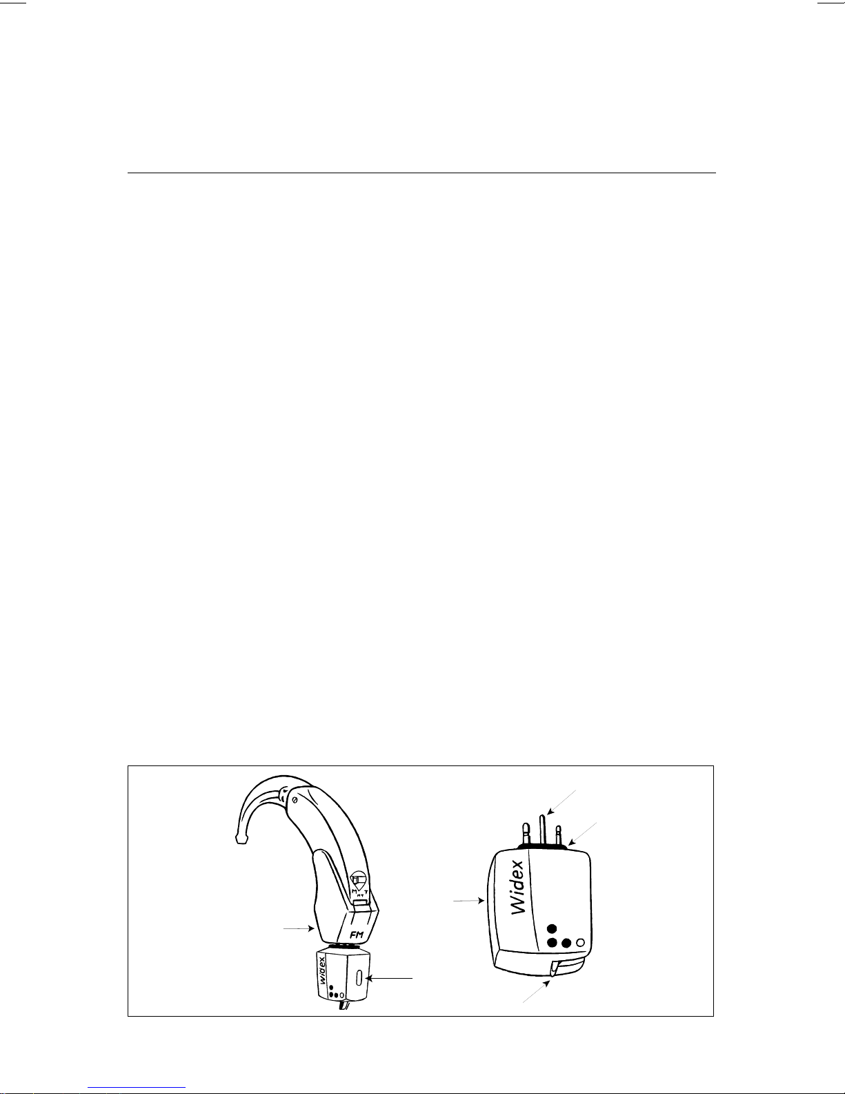
Description
1. FM shoe.
2. MicroLink receiver.
3. Europlug.
4. On/Off and function switch
(M – FM – M+FM).
5. Channel identification
The number and colour code indicate which
frequency is being used. The number and col
our of the receiver must be identical to the
number and colour of the transmitter.
6. Serial number. We recommend that you write
down this number.
-
9
Page 10
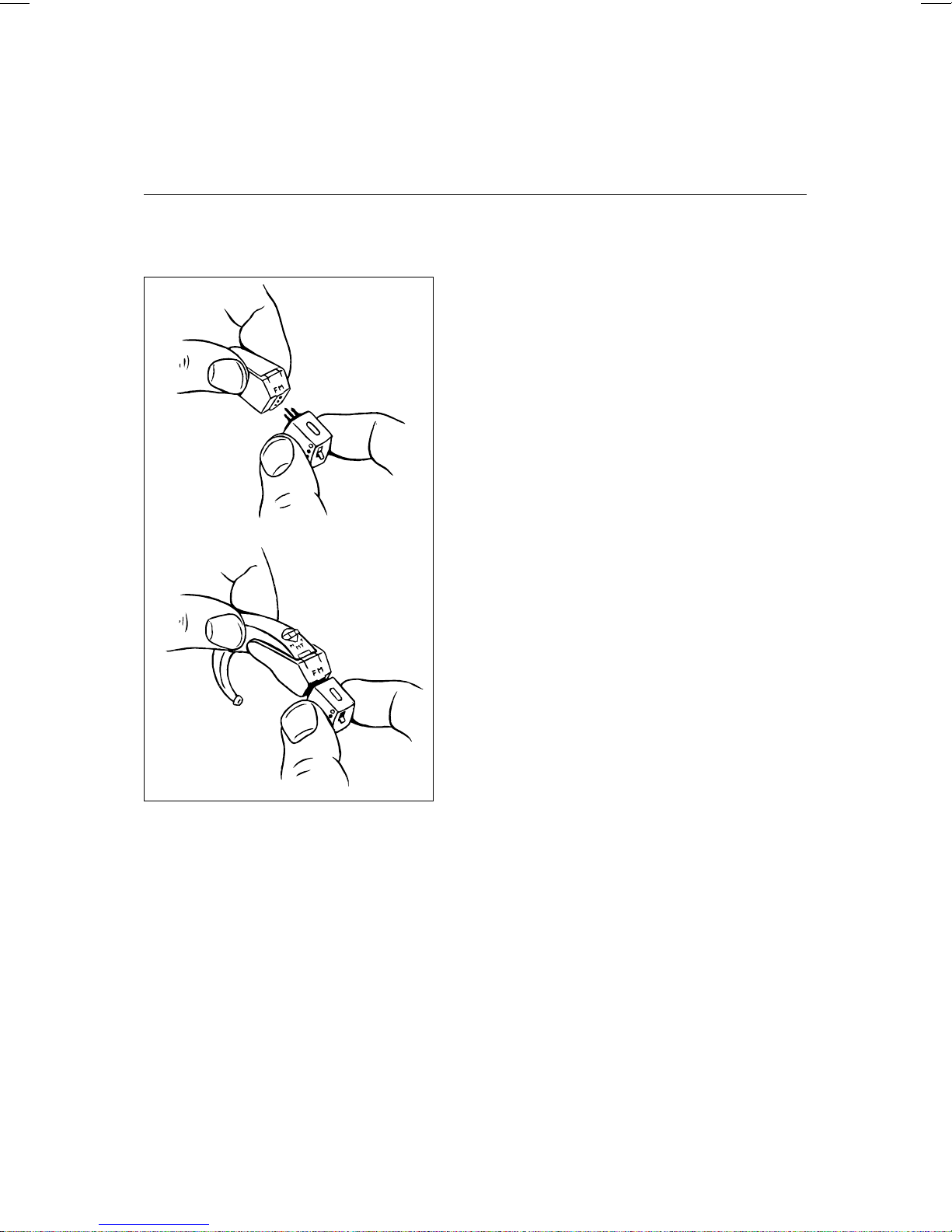
Attaching and removing the MicroLink
Attaching the MicroLink
to your hearing aid is a
two-step process. Firstly,
the MicroLink is con
nected to the FM shoe,
which, in turn, is con
nected to the hearing aid.
Place the MicroLink on
the FM shoe. Insert the
short, thick pin of the
MicroLink plug into the
corresponding hole in the
FM shoe. Push the
MicroLink plug into the
shoe until a “click” is felt.
The shoe with the MicroLink receiver is then con
-
-
nectedtothe hearing aid. Please check thesection
on “Audio input” in the user’s instructions for
your hearing aid for information on how to attach
and remove the audio shoe.
10
Page 11

Note: Please remember to exchange the solid
cover for the perforated cover on the side of the
hearing aid.
Reverse the procedure to remove the MicroLink.
11
Page 12

Operating the MicroLink receiver
The switch on the receiver can be set to three dif
ferent functions:
a. In position
m the receiver is switched off and
does not consume battery power. Only the
hearing aid’s own microphone is active. It is
therefore not necessary to remove the
MicroLinkfromyourhearingaid when not us
ing the FM system.
b. In position
l only FM is received (the hearing
aid’s microphone is dampened by 20 dB).
c. In position
ll both FM and the signals from
the hearing aid’s microphone are received.
-
-
Please remember to also switch on the transmit
ter (MicroVox or HandyMic).
The hearing aid’sM– MT – T switch modes will
retain their original functions when the
MicroLink is connected. This will result in a num
ber of possibilities as shown in the overview.
-
-
12
Page 13

MicroLink
m
l
ll
switch
Hearing
aid switch
Off
FM
reception
Combined
FM and
hearing aid
microphone
M Hearing
aid micro
phone
MT Hearing
aid micro
phone +
telecoil
-
-
FM
reception
FM
reception +
telecoil
FM reception +
hearing aid
microphone
FM reception +
hearing aid
microphone +
telecoil
T Telecoil Telecoil Telecoil
Please note – When switched on, the MicroLink
consumes battery power. Therefore, when not in
use the MicroLink should be switched off or
removed from the hearing aid.
13
Page 14

The HandyMic transmitter
How the HandyMic works
The HandyMic is a low power radio transmitter
with a built-in multidirectional microphone sys
tem. The transmitter sends signals from the
microphone to the MicroLink receiver. Please
note that the transmitter and the receiver must
be on the same channel/frequency.
The HandyMic can be used as a hand-held micro
phonewithout the externalantenna.The distance
to the MicroLink receiver should normally not
exceed 1.5 meters (4.5 feet). At this range the
HandyMic’s stand serves adequately as an
antenna. If the HandyMic’s operating range is
between 1.5 metres (4.5 feet) and 15 meters (50
feet), for example at a lecture, you must use the
-
-
accompanying external antenna.
14
Page 15

The integrated multidirectional microphone can
be adjusted to pick up signals in three different
modes:
1. The omnidirectional microphone picks up
sound signals from all directions.
2. The directional microphone primarily picks
up sound signals from an angle of 45° in front
of the microphone.
3. The super-directional microphone primarily
picks up sound signals from an angle of 20° in
front of the microphone.
Select the required mode on the microphone
switch depending on the distance to the speaker,
and the surrounding noise. This switch also
serves as the on/off switch.
Remember to switch off the transmitter when you
do not use it.
15
Page 16

The HandyMic can also be connected directly to
the headphone outlet of your radio or TV by
meansof the accompanyingaudiocord. Thetrans
mitter is automatically switched on even when it
is in the off position when there are incoming
audio signals. The audio cord then also functions
as an antenna.
A built-in rechargeable battery powers the
HandyMic. A fully charged battery will last
approximately one day. It can be recharged every
night with the battery charger.
-
16
Page 17

Description
2.
6.
5.
1.
3.
8.
4.
7.
1. Microphone mode switch and on/off switch.
Switch symbols:
l HandyMic off
m Omnidirectional
Directional
Super-directional.
2. Adapter socket.
3. Battery indicator.
17
Page 18

4. Audio socket for connection to audio-visual
equipment such as radio and TV.
5. Microphone stand. Functions also as a short
range antenna.
6. Microphone opening.
7. Compartment with cover containing the fre
quency module. The frequency module is al
ready in place in the compartment on the
underside of the HandyMic. The HandyMic’s
frequency module has a channel number
which must match the channel number of the
MicroLink receiver in order to function. The
frequency module can be replaced so that the
HandyMic is able to transmit on another
channel.
8. On the underside: Serial number, approval la
bel, and label for your name and address. We
recommend that you write down the serial
-
-
-
number in these instructions.
18
Page 19

HandyMic accessories
The HandyMic comes with the following accesso
ries:
1. Charger / power supply.
2. External antenna.
3. Audio cord for radio, TV, etc. with a 3.5 mm
jack and an additional 6 mm adapter jack.
4. Neck cord.
5. Leather case.
1.
5.
-
2.
3.
4.
19
Page 20

Microphone switch modes
Omnidirectional setting
The omnidirectional setting is ideal
for situations with some noise or
disturbance when you want to lis
ten to the people around you. At
small meetings, for example, the
HandyMic can be placed on the
table in a central position relative to the people
present.
Directional setting
The directional setting can be used
in situations when several people
are speaking at the same time. The
directionalmode is idealinsuch sit
uations since the microphone can
-
-
whom you are having a conversation. Sur
rounding conversation and ambient noise are
thus subdued.
be pointed towards the person with
-
20
Page 21

Super-directional
To further enhance the directional
mode to a specific person, switch to
super-directional mode. Only
speech and sounds that come pre
cisely from the direction in which
the microphone is pointing will be
amplified. Ambient noise and speech are signifi
cantly suppressed.
-
-
21
Page 22

Instructions for use of the HandyMic
The HandyMic can be used for different listening
situations:
1. Speaking with another person face to face.
2. Speaking with several people at the same
time.
3. Attending a lecture or a class.
4. Listening to the radio or TV directly through
the audio output or having a telephone con
versation (a telephone connecting cord can be
acquired from a supplier of assistive listening
devices).
-
22
Page 23

1. The companion technique
This technique is
used when you carry
on a conversation in
the street, in a car,
on a bus, etc. Here,
your companion can
either hold the HandyMic in his or her hand, slip
it into a shirt pocket or wear it on the accompany
ing neckcord. Speech will be transmitted directly
to the MicroLink receiver on the hearing aid. The
external antenna should always be utilised when
another person has the HandyMic.
-
23
Page 24

The antenna can be connected in two positions
(see figs.). Always keep the antenna cord untan
gled.
-
24
Page 25

2. The interview technique
Thistechniqueis ideal fordifficultlistening situa
tions when you wish to listen to different speak
ers. This is done by pointing the HandyMic
towards the person you want to hear – just as a
news reporter would.
When you use the
interview technique,
irrelevant talk and
noise are effectively
suppressed by setting
the HandyMic in the
directional or superdirectional mode.
-
-
Inquietsurroundings, choose the omnidirectional
mode and place the HandyMic in a central posi
tion (relative to the people you want to listen to).
The external antenna is probably not needed
when you use the interview technique as the
range between the MicroLink receiver and the
HandyMic does not exceed 1.5 m (4.5 feet). As a
rule of thumb, the microphone stand antenna is
sufficient when you hold the HandyMic in your
hand or place it within anarm’s length from your
self.
-
-
25
Page 26

3. The lecture technique
This technique is
used when you
want to hear a lec
turer, a teacher,
or another person
as distinctly as if
you were standing
beside him. The
lecturer should
either have the
HandyMic in the neckcord or wear it in front of
him. Select a microphone mode according to the
situation. For example, if the speaker is standing
still with the HandyMic placed on a table in front
ofhim– choose thedirectionalmode. The external
-
antenna should be connected to the HandyMic in
such situations.
26
Page 27

4. The audio-visual technique
With the accompanying
audio cord, the HandyMic
can be connected directly to
your TV, radio, telephone or
other audio-visual equip
ment such as a compact disc
player, cassette player, or a
loudspeaker installation provided the equipment
is fitted with a socket for a headphone jack (3.5
mm jack).
This allows you to get an optimum signal directly
from the TV, for example, without having to turn
up the volume. On some TV models, the loud
speaker is turned off when the audio cord is used.
Alternatively, the HandyMic can be connected to
the video recorder by a suitable lead. If necessary,
your radio/TV dealer can modify your TV so the
-
-
sound is not turned off when the audio cord is
used.
27
Page 28

When transmitting audio-input signals, the
HandyMic should be switched off. It is automati
cally switched on when a signal isreceivedvia the
audio cord. It is automatically switched off when
no signal has been received for 50 seconds. We
recommend that you recharge your HandyMic
when using radio, TV or similar equipment.
-
28
Page 29

The audio cord that comes with the HandyMic fits
most standard headphone sockets. If the audio
cord jack does not fit your audio-visual equip
ment,anadapter jack can be purchased fromyour
hearing healthcare professional. When connected
to the HandyMic, the audio cord also serves as an
antenna.
-
29
Page 30

Recharging the HandyMic
The HandyMic has a rechargeable NiMH (Nickel
Metal Hydride) battery. This is the most environ
mentally safe battery available. It does not con
tain heavy metals and has a high capacity and a
long life. A fully charged battery willlast approxi
mately 13 hours. A red light indicator (BAT)
flashes when the battery needs recharging.
-
-
-
30
Page 31

1. Plug the charger into the charger socket.
2. Connect the charger to the mains.
3. A continuous red light on the HandyMic indi
cates that the unit is being recharged.
4. Recharging a drained battery takes approxi
mately13 hours. Removethecharger cordand
the HandyMic is ready for use.
Please note:
The battery cannot be overcharged.
•
The HandyMic can be recharged while in use
•
with radio, TV or similar equipment.
We recommend that you replace the battery
•
when it can no longer be recharged to a full
-
-
day’s capacity. Please contact your hearing
healthcare professional.
31
Page 32

The MicroVox Transmitter
How the MicroVox works
The MicroVox is a lowpower radio transmitter
primarily intended for
educational environments.
The teacher wears it on a
belt with a connected
microphone clipped on to
his or her clothes. The
transmitter sends micro
phone signals to the
MicroLink receiver which
must be working on the same channel number as
the transmitter.
A1.5 V batterytype AA powersthe MicroVox. You
can use an ordinary alkaline battery or a
rechargeable battery. An alkaline battery comes
as standard. It has an operating time of approxi
mately 33 hours. A small light indicator starts
flashing when the battery is running low.
Remember to switch off the transmitter when you
-
-
do not use it.
32
Page 33

The MicroVox can be connected to the headphone
socket of a radio or TV by an audio cord. Audio
connection can be established in two ways; you
can use the socket for the microphone or you can
use an alternative audio input with a socket for a
2.5 mm jack plug.
Note: When connected to the microphone socket,
the audio cord also serves as an antenna. The
MicroVox will only function properly with this
antenna connection.
33
Page 34

Description
1. Microphone and audio socket. This connection
also serves as the antenna connection.
2. On/Off switch.
3. Alternativeaudio socket(2.5mm jack)forcon
nection to audio-visual equipment.
4. Channel number printed on a coloured back
ground. The colour indicates the last digit of
the channel number. (See page 9, item 5.)
5. Light indicator for battery power level.
6. Battery cover (bottom of the unit).
7. Clip with name label and any approval labels
(rear of the unit).
-
-
34
Page 35

1.
2.
4.
5.
3.
7.
6.
35
Page 36

MicroVox accessories
The MicroVox comes with the following items:
1. Clip-on microphone.
2. Alkaline battery.
3. Leather case.
1.
3.
2.
36
Page 37

The following items are optional:
Charger and cover for the MicroVox.
•
Power supply (adapter).
•
Audio cord for radio, TV, etc. with a 3.5 mm
•
jack socket.
A 6 mm jack plug adapter to fit a 3.5 mm jack
•
socket.
37
Page 38

Connecting the microphone
Insert the microphone plug into the microphone
socket on the MicroVox transmitter. Please note
the thickness of the pins – the plug can only be in
serted one way. Use only an original Widex micro
phone.
Important: The microphone connecting cord also
serves as an antenna. In order to function proper
ly there must be no loops or knots in the cord.
The clip-on microphone is a standard item that
should be attached externally to clothing 15-20
cm (6-8 inches) under the speaker’s mouth.
-
-
-
38
Page 39

The battery
a. b.
The MicroVox is supplied with a 1.5 V alkaline
battery size AA as standard. To place the battery
in its compartment, slide away the cover under
neath the MicroVox. The cover has a smaller
detachable panel available in two types:
a. A charge panel for rechargeable batteries
b. A solid panel for ordinary batteries
-
39
Page 40

The MicroVox comes with the panel for ordinary
batteries. A charger with a rechargeable battery
can be provided on request. In this case, the
charge panel that comes with the charger must be
used.
Please note: You have to remove the charge panel
to remove the battery.
40
Page 41

Inserting the battery
a. Open the battery compartment by sliding the
cover in the direction of the arrow.
b. Insert a new battery. A mark inside the com
partment shows the correct battery position.
Warning:Never leave batteries where young chil
dren or pets can reach them. If swallowed, seek
medical advice at once.
-
-
41
Page 42

How to switch on the MicroVox
Off
On
Switch on the MicroVox by pushing the on/off
switch downwards until a red mark is visible. If
the “Low Bat.” flashes, the battery requires re
placement or recharging.
-
42
Page 43

Connecting audio-visuals
The MicroVox has two connection alternatives.
Thesocketfor connecting the microphonecanalso
be used to connect TVs and radios. In both cases
the cord works as an antenna for the transmitter.
The audio cord is optional and can be ordered
from your hearing healthcare professional. A cord
with a 2.5 mm jack is necessary for the other
audio socket. The socket is intended for use when
signals from both the microphone and the
audio-visual equipment are required.
Note: There must always be a cord connected to
the three pin socket, as it also functions as the
antenna.
43
Page 44

Getting Started
Using the HandyMic may at first require an extra
effort because in doing so, you are showing every
one that you have a hearing loss. Try to ignore
this. Explain your situation.It may be a good idea
to practise on your family or friends. Everyone
will probably accept speaking into a microphone
when they hear that it gives you the possibility of
following a conversation on terms equal to – or
perhaps even better than – people with normal
hearing. So, never hesitate to ask someone to
carry and talk into the microphone.
Operating Range
Whether you use the HandyMic or the MicroVox
-
transmitter, the MicroLink system has an operat
ing range of 7-15 meters (20-50 feet) in a normal
meeting room, classroom, dining or living room
when the external antenna is used. Without the
external antenna connected to the HandyMic, the
microphone stand serves as an antenna. But in
this case, the operating range is limited to a maxi
mum of 1.5 meters (4.5 feet).
-
-
44
Page 45

The range of the MicroLink system depends pri
marilyonthe circumstances forradiowavepropa
gation (building construction, metal walls,
doorways etc.). The operating range is greatest in
open country and least inside steel buildings. Sig
nal fall-out with increased noise may occur in the
vicinity of the maximum range. Disturbances
from other kinds of transmitting equipment may
also affect reception.
Reception quality is also dependent on the condi
tion of the transmitter’s battery. When the bat
tery indicator light flashes, the HandyMic or
MicroVox will still function for some time, but at
reduced intensity.
-
-
-
-
45
Page 46

Maintenance
The maintenance advice applying to hearing aids
also applies to the MicroLink FM system. Below
youwillfindtips that we recommend you to follow
to allow your FM system to function optimally.
Daily maintenance
It is a good idea to check daily that everything is
functioning normally.
1. Listen to the hearing aid alone.
2. Listen to the hearing aid and the MicroLink
with FM+M switched on and the transmitter
switched off.
3. Listen to the MicroLinkwith both FM andthe
transmitter switched on.
4. Listen to the MicroLink with both FM+M and
the transmitter switched on.
5. Remove any dirt from the MicroLink, hearing
aid, and earmoulds with a cloth or tissue.
46
Page 47

The MicroLink receiver
Your hearing aid’s power consumption varies
depending on whether the MicroLink receiver is
turned off or on and therefore it is not easy to
know when the battery will run out. Make sure
you have one or more batteries in reserve at all
times.Change the batteryinyour hearingaidreg
ularly, and when you suspect that it is running
low.
If the battery is low, the MicroLink receiver will
stop functioning before the alarm on your hearing
aid startstobeep.Ifyourhearingaiddoesnotfea
ture a battery alarm, it will still function some
time after FM reception has been cut off.
HandyMic and
MicroVox with rechargeable battery
If your transmitter has a rechargeable battery, it
is a good idea to charge it daily. If the transmitter
-
-
is not in use for a period of time, store it with a
fully recharged battery.
47
Page 48

MicroVox with an ordinary battery
If your transmitter uses an ordinary battery, it is
a good idea to change it regularly. With an alka
line battery, the unit’s capacity is approx. 30
hours. When the battery is running low, the “low
battery” light flashes as a signal for you to change
the battery. It can, however, be functional for
some time, but do not wait until the battery is
completely dead. The signal quality received con
tinually deteriorates as the battery’s power is
reduced.
Periodic maintenance
It is a good idea to have your MicroLink system
checked periodically, for example every six
-
-
months, by a professional.
48
Page 49

Troubleshooting
Do not despair if your MicroLink system is not
functioningproperly.You can probablysolvemost
problems that may arise yourself. Below you will
findsomehelpful tips for generaltroubleshooting.
In order to identify the defect, listen to your
MicroLink system as recommended in the section
on daily maintenance.
49
Page 50

Symptom Cause Solution
No FM signal
from the re
-
ceiver, or
sound distor
-
tion.
The contact
points on the side
of the hearing
aid are covered
by the blind
plate.
The mode switch
of either the
hearing aid or
the MicroLink
receiver is in an
incorrect posi
-
tion.
The FM shoe is
not correctly con
-
nected.
Exchange the plate
with the one that co
-
mes with the FM shoe.
Check the position of
both mode switches.
Make sure that a
“click” is felt when you
connect the shoe to the
The hearing aid’s
contact points
are not clean.
hearing aid. The shoe
must have contact
with all of the hearing
aid’s contact points.
Clean the contact
points with a soft
cloth.
50
Page 51

Symptom Cause Solution
No FM signal
from the re
-
ceiver, or
sound distor
-
tion.
The transmitter’s
battery is run
-
ning low.
The microphone
is off (HandyMic)
or not connected
(MicroVox).
The earmould or
the tubing is
blocked.
Make sure that the
battery has sufficient
power. Check the low
battery indicator.
Switch on the
HandyMic transmitter
or test the MicroVox to
ensure that the micro
-
phone jack is correctly
connected.
Make sure that the
earmould is correctly
connected to the hear
-
ing aid. Check for wax
or dirt in the earmould
No audio sig
nal even
though the
signal from
the transmit
ter is OK.
The audio cord is
not correctly con
nected.
-
The audio cord or
jack is defective.
tubing.
Make sure that the
-
jack for the HandyMic
and for the audio
equipment is correctly
connected.
Check for visible dam
age to the cord or jack.
-
51
Page 52

Symptom
Cause
Solution
The trans
mitter cannot
be recharged.
-
No power supply. Check that the mains
outlet is switched on.
The power outlet
is not correctly
connected.
Check that the
charger is connected
correctly to the mains
outlet and that the
charger’s plug and
cable are intact.
If none of these tips work, please contact your
hearing healthcare professional for further infor
mation.
-
52
Page 53

Warning
1. Do not use two transmitters on the same fre
quency in the same area.
2. Do not try to disassemble your hearing aid or
the MicroLink FM system as this will make
the guarantee void.
3. Do not clean the system with water or other
fluids.
4. Do not try to charge ordinary (non-recharge
able) batteries.
5. Do not tangle or knot the antenna.
6. Do not expose the system to hair spray.
-
-
7. Do not use the MicroLink receiver together
with another person’s hearing aid unless you
are certain that the hearing aid fits the FM
shoe.
8. Do not use the MicroLink on aeroplanes or in
hospitals without permission.
53
Page 54

9. Notethatwhatis beingsaidinto the transmit
ter can possibly be picked up and heard via
other receivers.
-
10. Notethat you may possibly overhear other ra
dio communication when using theMicroLink
receiver.
-
54
Page 55

Warranty
A one-year international warranty is provided.
The warranty covers all material and manufac
turing defects. Defects arising from improper
handling or repairs carried out by an unauthor
ised party are not covered by this warranty.
Notes
-
-
55
Page 56

WIDEX
T&W, DK-3500 Vaerloese www.widex.com
P!FM0!0501!201L$
Printed by FB / 08-00
P FM0 0501 201
 Loading...