

Page 1
Standard Vent Clutches
Coupling Clutches
The Wichita Standard Vent Com bi na tion
Clutch-Coupling is designed for reliable
in-line power transmission. The simple
air-tube design, with small air vol ume,
speeds en gage ment and dis en gage ment.
It is un af fect ed by centrifugal force and has
no self-energization like drum clutch
de signs. Ideally suited for large inertia loads
where smooth controlled starts are needed.
See pages 131 thru 135.
Grinding Mill Clutches
Wichita Grinding Mill Clutches are
spe cial ly designed to provide
quick, smooth starts with limited
current surge for heavy duty
grinding mills. The clutch
is adapt able to remote control
allowing centralized op er a tion
through simple air or electric
circuits.
See pages 136 thru 143.
122 Wichita Clutch 800-964-3262
P-1100-WC 1/12
Page 2
Application Guidelines
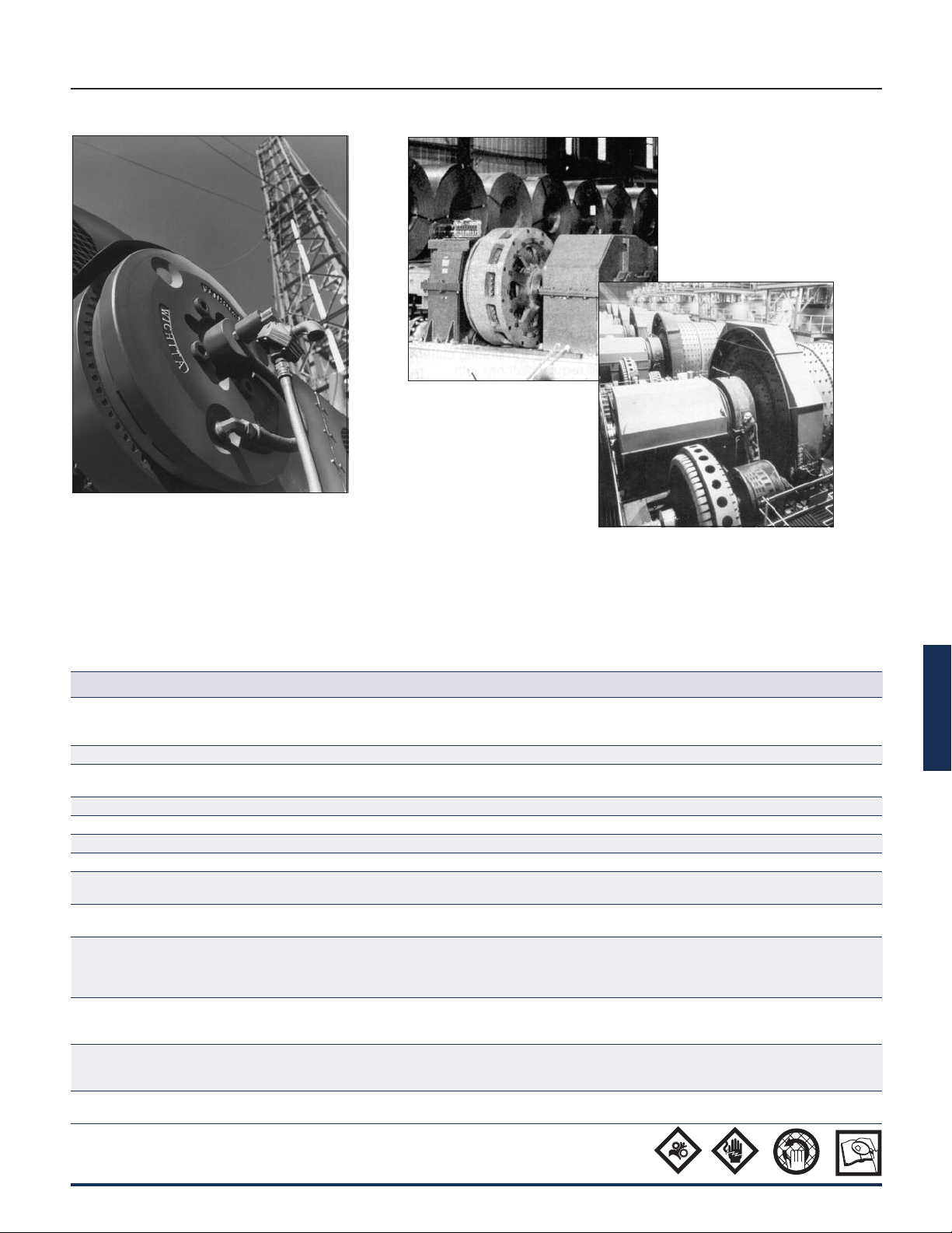
Reliable, trouble-free
Wichita Standard Vent
Clutches handle
maximum loads on
drilling rigs.
Standard Vent Clutches
Typical Applications
Wichita ATD-342 Clutches allow
smooth acceleration of coil
transporter.
Wichita Grinding Mill
Clutches provide shock-free
start-up of large inertia
loads.
Clutch selection is made by knowing the
application horse pow er/100 RPM, the
available air pressure, required torque and
the clutch heat horse pow er. The Re quire ments
Table (Chart A) gives application factors
ranging from light duty (the A group) to extra
heavy duty (the D group).
Chart A
Field of Application Group A Group B Group C Group D
Pumps Centrifugal Reciprocating compressors Reciprocating compressors
compressors over 2 cylinders, one or two cylinders
centrifugal fans & blowers
Agitators Liquid Semi-solid Solids
Brick Brick press, extruder, pug mill
manufacturing
Can & bottling machine Bottle-can feeders, filling, mixers
Engine driven equipment Crane, hoist, engine Crowd
Grinding mills Ball-rod-sag-pebble Crushers, shakers
Lumber processing Yarder Carriages, conveyers Chipper, logger
Marine Propulsion clutch CP wheel Shaft brakes, propulsion
reversing type, anchor winch
Bulk material Conveyors evenly loaded, Feeders Elevators
handling line shaft evenly loaded
Metal production & Coilers, slitters, press brake, Draw bench, rolling mill, Hammer mill, forming
metalforming non-geared press, geared press shear, back geared press, press, forging press,
deep draw press, transfer header press, knuckle press
press, toggle press
Paper industry dryer Fourdrinier to 500 FPM, Fourdrinier to 1800 RPM
sections & calenders paper mill plane & press selections, calenders
consult factory smoothing press & dryers
Petroleum Drilling & service rig master Mud pumps,
production clutches, compound clutches, PTO clutches
rotary, drum
Rubber Transfer machines Banberry mixer, drum mixer, Centrifuge
manufacturing evenly loaded extruder, calender
E
P-1100-WC 1/12
Wichita Clutch 800-964-3262 123
Page 3

Standard Vent Clutches
Coupling and Grinding Mill Clutches
Selection
Clutch sizes are affected by the following
variables:
1. Machines that operate under smooth loads
require smaller clutches. These machines
are driven by either multi-cylinder high
speed engines or electric motors with
reduced starting current.
2. Drives that require high starting current
motors will require clutches with sufficient
torque to prevent excessive slipping while
starting.
3. Starting torque may be high, which
re quires fast clutch response time to
transmit the required torque or extended
clutch slip time to protect the prime mover.
4. Starting torques may be very low
com pared to the normal torque, which
may result in the clutch not being fully
pres sur ized prior to the time of torque
re quire ment. This will cause the clutch
to over-heat from slippage. Clutch inflation
time in this instance is very important.
5. Clutches on most machines are designed
to slip prior to damage from shockloads.
As a result, the clutch may require periodic
maintenance; therefore the clutch should
be located, for easy access, in the power
train. Clutches should also be located for
maximum cooling air. In instances where
this is not possible, forced air cooling may
be nec es sary for extended clutch life.
6. Safe operating speeds for clutches should
be maintained in design. The following
material specifications are rec om mend ed
for safe operation. The max i mum speeds
shown are safe op er at ing speeds based
upon years of Wichita experience.
Maximum Clutch
Contact Velocity FPM Material
6,000 (Recommended upper limit for slip) cast iron
9,000 ductile iron
12,000 steel
These velocities are measured at the nominal
outside diameter of the clutch plates.
Selection Example
To properly select a clutch for your ap pli ca tion,
the following information is re quired:
1. Application horsepower
2. Re quired air pressure
3. Required torque
4. Clutch heat horsepower
5. Shaft diameter
Chart A (page 123) gives application re quire ments ranging from light duty (the A group) to
extra heavy duty (the D group). This chart will
give the initial se lec tion which is then compared
with the selection made using the Clutch Heat
Horsepower Chart B and the Clutch area (see
“lining area” column) in the Spec i fi ca tion Table
(Chart C, page 125-126).
Machine required:
Rock crusher (Grinding mill)
(Group D duty requirement)
PSI
2
HP
2
in.
WR2................................1,000 lb.ft.
RPM ..................................1,800
Clutch Slip Time ................6 sec.
HP......................................325 (diesel 8
............................................ cylinder)
Available air pressure ...
.....120
Clutch must slip while bringing equipment
up to speed.
Chart B
Clutch heat horsepower absorption rate*
ft.lb.
in.
Heat Input
2
Slip
Time
Seconds
0 to 1 380 .7
2 617 .56
3 820 .5
4 1,000 .45
5 1,175 .43
6 1,330 .4
7 1,485 .38
8 1,630 .37
9 1,770 .36
10 1,900 .34
* This chart is for use when clutch is at ambient temperature of 120°
F max.
124 Wichita Clutch 800-964-3262
P-1100-WC 1/12
Page 4

Standard Vent Clutches
Coupling and Grinding Mill Clutches
Calculations
Engine torque =
RPM 1800
Engine torque = 11,375 lb.in.
Clutch torque required while slipping:
Clutch torque =
(g) (t
W = Weight to be accelerated lb.
R = Radius of gyration ft.
g = Acceleration of gravity ft./sec.
ts= Time of slip, in seconds
T
= Clutch torque = 11,707 lb.in.
c
Clutch heat HP is 1/2 of the total
area in the diagram.
Clutch heat HP =
63,000
Clutch heat HP =
63,000
From Clutch Heat Horsepower (Chart B)
for a 6 second start:
2
HP / in.
Area required =
.4
= .4
To properly select a clutch for this rock
crusher application, the following
information is required:
1. Application horsepower
2. Re quired air pressure
3. Required torque
4. Clutch heat horsepower
5. Shaft diameter
The Specification Table on pages 126-127 gives
ap pli ca tion factors ranging from light duty (the A
group) to extra heavy duty (the D group). This
chart will give the initial se lec tion which is then
compared with the selection made using the
Clutch Heat Horsepower Chart and the Clutch
Area Chart.
(HP) (63,000) =(325) (63,000)
2
(WR
) (RPM) (π) lb.in.
) (2.5)
s
2
2
(T
c) (input RPM)
(11,375) (1,800)
(1/2)
(1/2)
= 162.5 HP
162.5
= 406 in.
2
How to select
Clutch torque
energy
rotating
mass
Torque
clutch
heat horsepower
RPM
1. The area required is 406 inches. Consult the
column head “Lining Area” in Spec i fi ca tion
Table (pages 126-127). Applicable clutch es
chosen are:
ATD-218, 528 in.
ATD-314H, 504 in.
2
; ATD-124H, 574 in.2;
2
2. Determine the application
horsepower necessary:
HP/100 RPM =
1,800
325
(100) HP
HP/100 = 18 HP/100 RPM
Clutches selected with this application
horsepower are as follows:
ATD-214H 18 HP/100 RPM, ATD-314H
27 HP/100 RPM, ATD-118 21 HP/100 RPM.
The ATD-314 is selected as having both
sufficient area and torque with min i mum
diameter.
Contact velocity =
12
(clutch size) (π) (1,800)
= 6,597 ft./min.
Ductile material required.
Note: This application example is for
pre lim i nary sizing only. Contact a Wichita Sales
Engineer or the factory for final selection.
Use engine torque for calculations.
When selecting the proper clutch, heat must
be considered. When a clutch is slipped under
load, heat is gen er at ed within the clutch. This
heat as shown to the left is equal to the energy
of the mass that was ac cel er at ed to speed by
the clutch.
Input RPM
E
P-1100-WC 1/12
In applications where thermal re quire ments are
of concern, consult factory for special
ventilated and super ventilated clutch options.
Wichita Clutch 800-964-3262 125
Page 5
Standard Vent Clutches
Coupling and Grinding Mill Clutch Selection
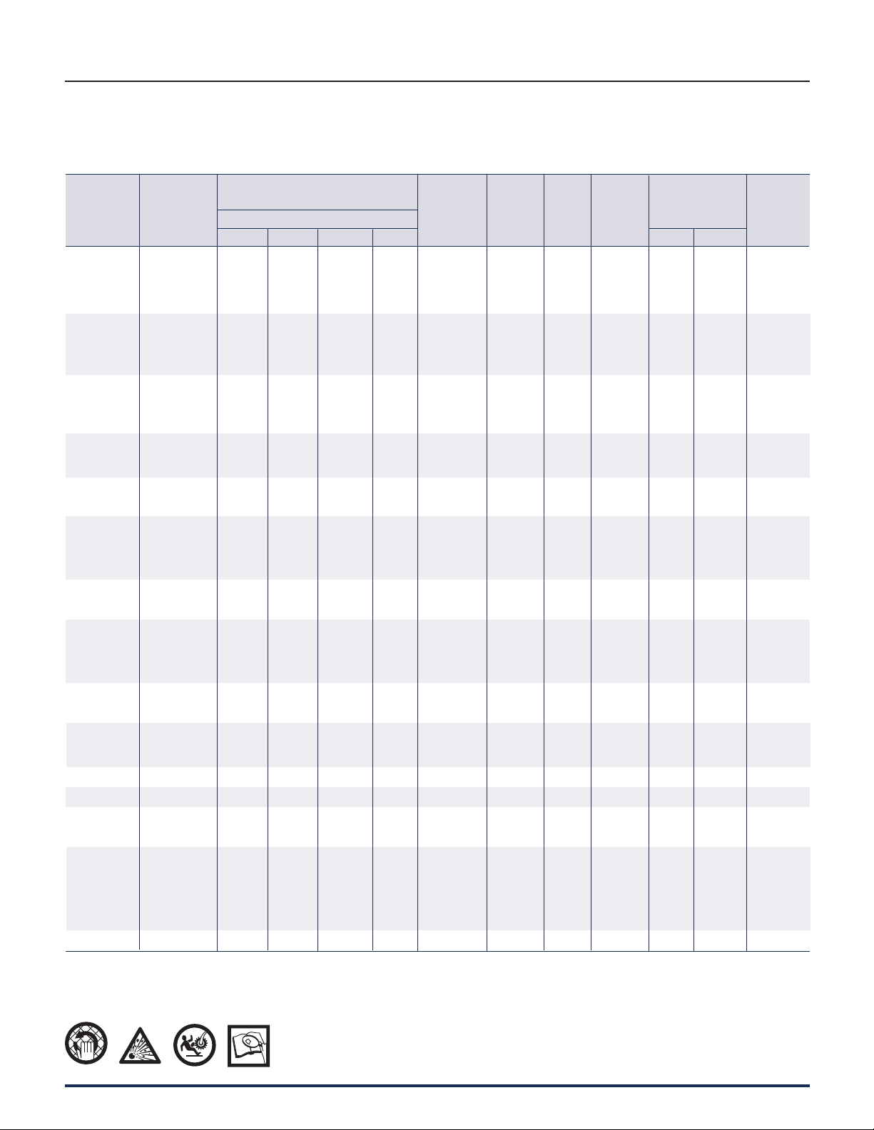
Specifications
Chart C
Recom- Hi-Spd.
Slip Torque mended Airtube
Model lb.in. Clear- Max. Total Total Lining
Size at 100 PSI ances Speed Wt. WR2 Area
ATD– .3 CF A B C D Inches RPM lb. lb. ft.2 Wt. WR
108 STVC 7,000 11.1 8 4 2 1/16-1/8 3,000 36 3 8 1.2 56
208 STVC 14,000 22.2 16 8 4 3/32-5/32 3,000 58 38 18 1.8 112
308 STVC 21,000 33.3 24 12 6 3/32-5/32 3,000 80 5.1 28 2.4 168
111 STVC 15,900 25 18 9 5 1/16-1/8 2,800 65 11 20 5 114
211 STVC 31,800 50 37 18 10 3/32-5/32 2,800 106 18 37 10 228
311 STVC 47,700 75 55 27 15 3/32-5/32 2,800 147 25 54 15 342
114H STVC 35,800 56 40 20 9 1/16-1/8 2,200 165 55 38 14 168
214H STVC 71,600 113 80 40 18 3/32-5/32 2,200 220 75 58 24 336
314H STVC 107,400 170 120 60 27 3/32-5/32 2,200 275 85 78 34 504
116 STVC 40,400 64 45 22 11 1/16-1/8 2,200 189 62 41 23 228
216 STVC 80,800 134 90 44 22 3/32-5/32 2,200 272 87 90 47 456
118 STVC 64,500 102 75 35 21 1/16-1/8 2,000 266 95 47 33 264
218 STVC 129,000 204 150 70 42 3/32-5/32 2,000 390 150 65 63 528
118H STVC 75,000 119 85 40 21 1/16-1/8 1,650 290 103 47 33 264
218H STVC 150,000 238 175 80 42 3/32-5/32 1,650 415 160 65 63 528
318H STVC 225,000 357 260 120 63 1/8-3/16 1,650 540 215 83 153 792
221STVC 175,300 278 195 97 49 3/32-5/32 1,650 500 256 127 114 724
321 STVC 263,000 417 300 150 84 1/8-3/16 1,650 735 360 210 185 1,086
124H STVC 153,700 243 180 90 40 3/32-5/32 1,400 580 390 90 100 574
224H STVC 307,400 487 360 180 80 1/8-3/16 1,400 790 535 180 200 1,148
324H STVC 461,100 731 540 270 120 5/32-7/32 1,400 1000 680 270 300 1,722
227 STVC 345,000 548 383 192 96 1/8-3/16 1,400 890 700 200 275 1,460
327 STVC 517,500 821 600 300 165 5/32-7/32 1,400 1,200 945 265 350 2,190
230H STVC 654,000 1,038 760 380 200 1/8-3/16 1,100 1,375 1,350 265 460 1,664
330H STVC 981,000 1,557 1,150 570 300 3/16-1/4 1,100 2,500 2,325 380 570 2,496
336 STVC 1,524,000 2,418 1,800 885 495 3/16-1/4 900 2,700 3,770 540 1,260 3,450
342 STVC 2,179,000 3,458 2,550 1,275 705 3/16-1/4 800 3,600 7,700 1,100 3,375 4,212
248 STVC 2,805,000 4,452 3,200 1,600 915 1/8-3/16 700 4,500 11,200 785 3,130 4,020
348 STVC 4,207,500 6,678 4,800 2,400 1,370 3/16-1/4 700 5,590 13,850 1,140 4,360 6,030
260 STVC 5,950,000 9,440 6,950 3,470 1,940 3/16-5/16 550 7,525 24,700 1,665 9,400 7,240
360 STVC 8,925,000 14,160 10,400 5,200 2,900 1/4-3/8 550 9,350 32,250 2,500 14,020 10,850
460 STVC 11,900,000 18,880 13,900 6,940 3,880 5/16-7/16 550 12,000 41,000 2,900 16,615 14,480
560 STVC 14,875,000 23,611 16,528 8,264 4,132 1/2-9/16 550 11,750 — — — 18,100
372 STVC 13,965,000 22,167 15,517 7,758 3,879 5/16-7/16 400 — — — — 14,460
Note: Maximum air pressure – 100 PSI
Max. Horsepower
Per 100 RPM
Duty
Driving Ring
& Friction
Disc
2
2
in.
126 Wichita Clutch 800-964-3262
P-1100-WC 1/12
Page 6

Standard Vent Clutches
Coupling and Grinding Mill Clutch Selection
Specifications
Inflation Coefficient
Operating Air Pressure
50 PSI
K U K U K U R E V R E V R E V
15,800 2.2 7,100 2 265 1.2 60 .016 1 525 .02 1.6 240 .02 1.4
890 1.7 880 1.6 5,100 2.2 1,000 .032 2 8,200 .04 2.8 4,930 .048 2.8
456 2 825 2.2 300 1.75 3,180 .068 3 8,270 .076 3.5 8,000 .088 3.7
456 2 825 2.2 300 1.75 3,180 .068 3 8,270 .076 3.5 8,000 .088 3.7
9,600 3.1 1,560 2.4 9,600 3.8 44 .068 1.4 40 .072 1.4 34 .08 1.4
1,350 2.5 1,350 2.5 1,350 2.5 113 .052 1.6 36 .064 1.3 630 .076 2.5
75 PSI 100 PSI
50 PSI
Exhaust Coefficient
Operating Air Pressure
75 PSI 100 PSI
1,350 2.5 1,350 2.5 1,350 2.5 71 .07 1.6 26 .077 1.3 490 .084 2.5
145 1.8 90 1.6 87 1.6 360 .096 2.5 240 .112 2.5 270 .136 2.8
145 1.8 90 1.6 87 1.6 360 .096 2.5 240 .112 2.5 270 .136 2.8
185 2 150 2 93 1.8 120 .104 2.1 140 .128 2.4 146 .158 2.7
170 2 250 2.2 160 2 124 .112 2.2 92 .128 2.2 76 .152 2.3
115 2 125 2 111 2 132 .12 2.3 89 .144 2.3 6.1 .168 2.3
25 1.6 22 1.6 26 1.8 20 .224 2 20 .256 2.2 19 .308 2.5
28 1.8 22 1.8 20 1.8 24 264 2.4 10 .304 2.3 9.9 .352 2.2
E
P-1100-WC 1/12
Wichita Clutch 800-964-3262 127
Page 7

Standard Vent Clutches
Coupling and Grinding Mill Clutch Selection
Specifications
Model Clutch Mounting Assembly Drawing
Size ATD- Options Number Number
STV 108
STV 208
STV 308
STV 111 Clutch w/ QCDA 6-211-100-303-0 -904-9
STV 211 Clutch w/ QCDA 6-111-200-311-0 -912-9
STV 311 Clutch w/ QCDA 6-111-300-303-0 -903-9
STV 114H Clutch w/ QCDA 6-115-100-300-0 -903-9
STV 214H Clutch w/ QCDA 6-115-200-300-0 -907-9
STV 314H Clutch w/ QCDA 6-115-304-300-0 -900-9
STV 116 Clutch w/ QCDA —
STV 216 Clutch w/ QCDA —
STV 316 Clutch w/ QCDA —
STV 118 Clutch w/ QCDA —
STV 218 Clutch w/ QCDA —
STV 318 Clutch w/ QCDA —
Note: QCDA - Quick Change Driving Adapter. A favorite of OEMs for the extra clearance gap between the clutch and Quick Change Driving Adapter, making the clutch
maintenance less time consuming. SDA - Standard Driving Adapter. A close couple design where clutch maintenance is not of prime importance.
Clutch only 6-208-100-110-0 -900-9
Clutch w/ SDA 6-208-100-302-0 -901-9
Clutch only 6-208-200-103-0 -900-9
Clutch w/ SDA 6-208-200-309-0 -901-9
Clutch only 6-208-300-101-0 -900-9
Clutch w/ SDA 6-208-300-304-0 -901-9
Clutch only 6-211-100-101-0 -900-9
Clutch w/ SDA 6-211-100-304-0 -905-9
Clutch only 6-111-200-101-0 -902-9
Clutch w/ SDA 6-111-200-312-0 -913-9
Clutch only 6-111-300-103-0 -901-9
Clutch w/ SDA 6-111-300-304-0 -904-9
Clutch only 6-115-180-102-0 -902-9
Clutch w/ SDA 6-115-100-301-0 -904-9
Clutch only 6-115-280-104-0 -903-9
Clutch w/ SDA 6-115-200-301-0 -908-9
Clutch w/ DIC Flange Ring 6-115-204-301-0 -900-9
Clutch only 6-115-380-100-0 -901-9
Clutch w/ SDA 6-115-300-100-0 -100-9
Clutch w/ DIC Flange Ring 6-115-300-104-0 -904-9
Clutch only 6-116-100-112-0 -900-9
Clutch w/ SDA —
Clutch only 6-116-200-121-0 -900-9
Clutch w/ SDA —
Clutch only 6-116-300-118-0 -901-9
Clutch w/ SDA —
Clutch only 6-118-100-120-0 -904-9
Clutch w/ DIC Flange Ring 6-118-100-304-0 D-3545
Clutch only 6-118-200-143-0 -909-9
Clutch w/ DIC Flange Ring 6-118-204-300-0 -901-9
Clutch only 6-118-300-309-0 -908-9
Clutch w/ DIC Flange Ring 6-118-300-311-0 -909-9
Model Clutch Mounting Assembly Drawing
Size ATD- Options Number Number
Clutch only 6-119-100-100-0 -900-9
STV 118H Clutch w/ QCDA —
Clutch w/ SDA —
Clutch only 6-119-200-100-0 D-3709
STV 218H Clutch w/ QCDA 6-119-200-106-0 -106-9
Clutch w/ SDA —
Clutch only 6-119-300-100-0
STV 318H Clutch w/ QCDA —
Clutch w/ SDA 6-119-304-305-0 -908-9
Clutch only 6-121-100-106-0 D-2769
STV 121 Clutch w/ QCDA —
Clutch w/ SDA —
Clutch only 6-121-200-143-0 -903-9
STV 221 Clutch w/ QCDA —
Clutch w/ SDA —
Clutch only 6-121-300-120-0 -904-9
STV 321 Clutch w/ QCDA —
Clutch w/ DIC Flange Ring 6-121-300-312-0 -912-9
Clutch only 6-125-100-110-0 -900-9
STV 124H Clutch w/ QCDA —
Clutch w/ SDA —
Clutch only 6-125-200-129-0 -915-9
STV 224H Clutch w/ QCDA —
Clutch w/ SDA —
Clutch only 6-125-300-113-0 -912-9
STV 324H Clutch w/ QCDA —
Clutch w/ SDA —
Clutch only 6-127-100-112-0 -901-9
STV 127 Clutch w/ QCDA —
Clutch w/ SDA —
Clutch only 6-127-200-130-0 -905-9
STV 227 Clutch w/ QCDA 6-127-200-127-0 -905-9
Clutch w/ SDA —
Clutch only 6-127-300-112-0 -903-9
STV 327 Clutch w/ QCDA —
Clutch w/ SDA —
Clutch only 6-131-100-101-0 D-4008
STV 130H Clutch w/ QCDA —
Clutch w/ SDA —
Clutch only 6-131-200-307-0 -903-9
STV 230H Clutch w/ QCDA —
Clutch w/ SDA —
Clutch only 6-131-300-303-0 -904-9
STV 330H Clutch w/ QCDA —
Clutch w/ SDA —
128 Wichita Clutch 800-964-3262
P-1100-WC • 1/11
Page 8

Standard Vent Clutches
Coupling and Grinding Mill Clutch Selection
Specifications
Model Clutch Mounting Assembly Model Clutch Mounting Assembly
Size ATD- Options Number Size ATD- Options Number
Clutch only —
STV 430H Clutch w/ QCDA — STV 248
Clutch w/ SDA —
STV 236 Clutch only 6-136-200-107-0
Clutch w/ QCDA —
Clutch w/ SDA —
STV 336 Clutch only 6-136-300-109-0
Clutch w/ QCDA —
Clutch w/ SDA —
STV 336H Clutch only 6-137-300-300-0
Clutch w/ QCDA 6-137-300-301-0 STV 260
Clutch w/ SDA —
Clutch only 6-142-200-301-0
STV 242 — STV 360
Clutch w/ SDA —
Clutch only 6-142-300-300-0
STV 342 Clutch w/ QCDA — STV 460
Clutch w/ SDA —
Clutch only —
STV 442 Clutch w/ QCDA — STV 560
Clutch w/ SDA —
Note: QCDA - Quick Change Driving Adapter. A favorite of OEMs for the extra clearance gap between the clutch and Quick Change Driving Adapter, making the clutch maintenance less time consuming.
SDA - Standard Driving Adapter. A close couple design where ease of clutch maintenance is not of prime importance.
STV 348
STV 448
Clutch only 6-148-200-100-0
Clutch w/ QCDA
Clutch only 6-148-300-100-0
Clutch w/ QCDA —
Clutch only —
Clutch w/ QCDA —
Clutch only 6-160-200-307-0
Clutch w/ QCDA —
Clutch only 6-160-300-304-0
Clutch w/ QCDA —
Clutch only —
Clutch w/ QCDA 6-160-430-301-0
Clutch only —
Clutch w/ QCDA 6-160-582-300-0
—
E
P-1100-WC • 1/11
Wichita Clutch 800-964-3262 129
Page 9

Standard Vent Clutches
Coupling and Grinding Mill Clutch Selection
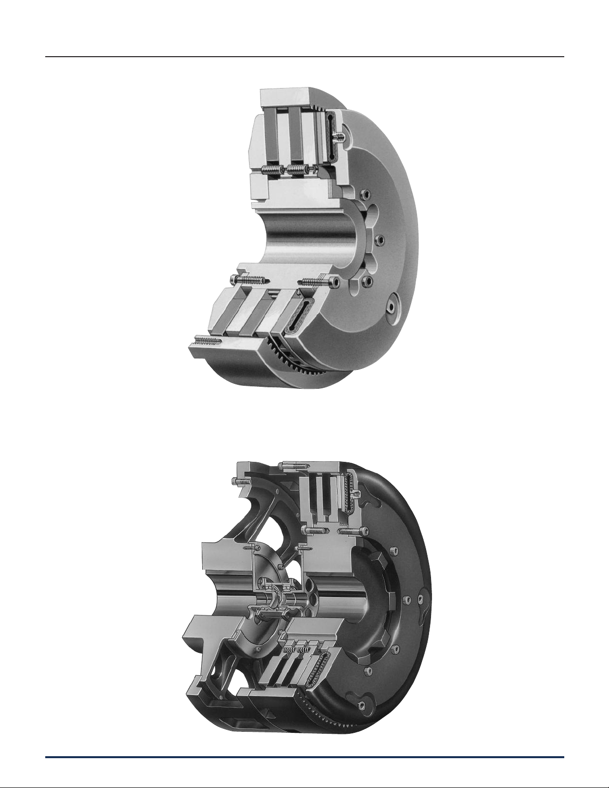
Component Parts
1. Hub
2. Hex Head Bolt
3. Backplate
4. Shim
5. Driving Ring
6. Friction Disc
7. Release Spring
8. Center Plate
130 Wichita Clutch 800-964-3262
9. Pressure Plate
10. Hose Assembly
11. Air Tube
12. Air Tube Holding Plate
14. Socket Head Capscrew
16. Elbow
17. Bolt (Furnished by cus tom er)
P-1100-WC 1/12
Page 10

• In-line power applications
• Smooth, controlled acceleration
• Unaffected by centrifugal force
Releasing springs insure
complete disengagement.
Air passages through
clutch greatly assist in
keeping clutch cool.
Standard Vent Clutches
Coupling Clutches
Optional high speed air tube
reinforced to withstand speeds
even greater than permissible
with cast iron.
All air connections on
outside for easy access.
Demountable back
plate for accessibility.
(Optional)
Friction discs available in
halves easily replaceable
without dismounting.
Full width molded composition
teeth on friction disc minimize
wear on driving ring.
The Wichita Standard Vent Combination
Clutch-Coupling is designed for reliable
in-line power transmission. The simple
air-tube design, with small air volume,
speeds en gage ment and dis en gage ment.
It is un af fect ed by centrifugal force and has
no self-energization like drum clutch designs.
Ideally suited for large inertia loads where
smooth controlled starts are needed.
The Wichita air-tube disc design combines all
the best features of a disc type clutch with all
the advantages of direct air en gage ment. It is
E
Air-tube easily
replaceable without
dismounting by simply
removing these
capscrews.
the simplest and most trouble-free method of
applying air pres sure yet designed.
Problems of speed, smoothness, en gage ment
or disengagement with all types of
loads…problems of compactness …prob lems
of simplifying main te nance and many other
prob lems in a wide range of ap pli ca tions are
quickly solved with Wichita clutches or
brakes.
P-1100-WC 1/12
Wichita Clutch 800-964-3262 131
Page 11

Standard Vent Clutches
Coupling Clutches
Notes:
1. Air Hose Kits, page 141.
2. Quick Release Valves, page 144.
3. Roto-couplings, page 144.
Note: For mounting, use socket head capscrews conforming to the ASTM-574-97a.
132 Wichita Clutch 800-964-3262
P-1100-WC 1/12
Page 12

Standard Vent Clutches
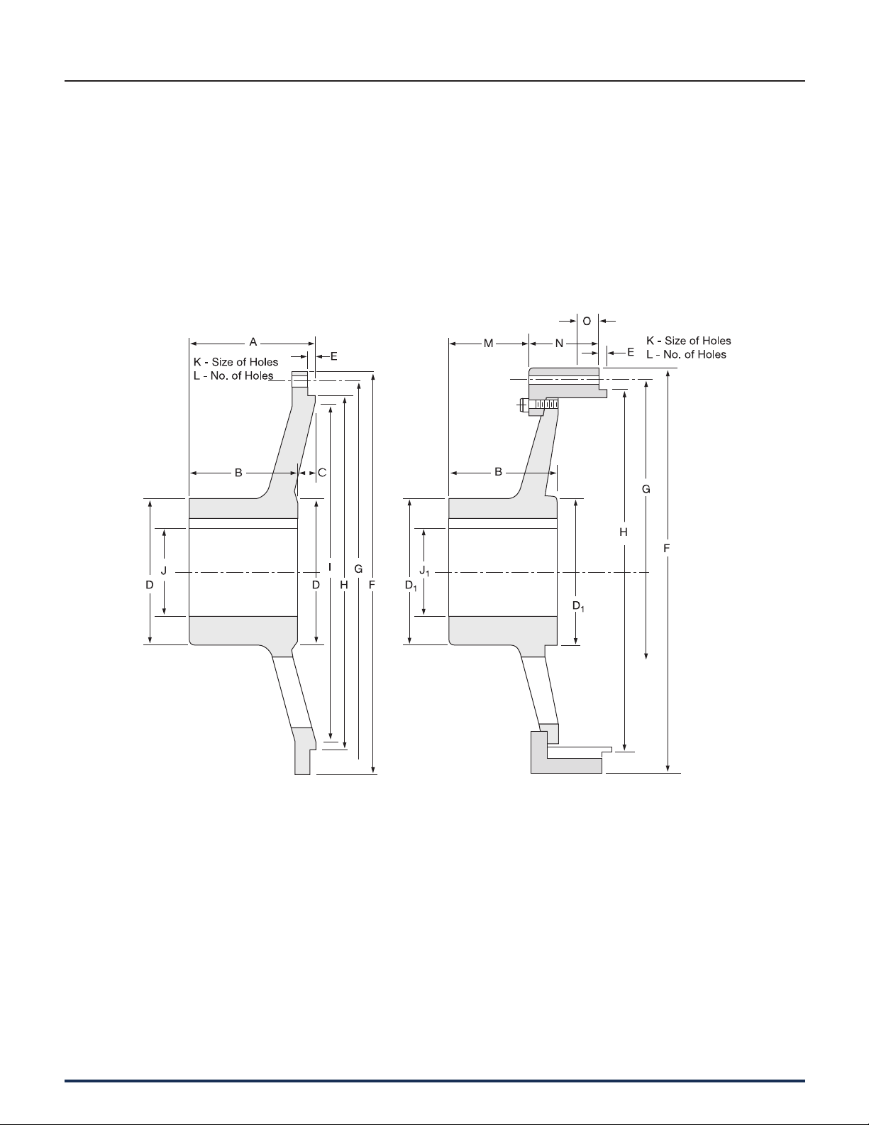
Coupling Clutches
Dimensions: inches (Consult factory for drawing before final layout.)
Model +.003" Max Bore
Size -.000" Rect. Key
ATD– A B C D E F G H I J
108 STVC 9.625 8.873 8.50 8 8 1.93 2.75 1.938 6.625 9.625
208 STVC 9.625 8.873 8.50 8 8 1.93 4.125 1.938 6.625 9.625
308 STVC 9.625 8.873 8.50 8 8 1.93 5.50 1.938 6.625 9.625
111 STVC 13.375 12.375 12 11 11 3.00 3 3 8.50 11.938
211 STVC 13.375 12.375 12 11 11 3.00 4.25 3 8.50 11.938
311 STVC 13.375 12.375 12 11 11 3.00 5.563 3 8.50 11.938
114H STVC 16.25 15.125 14.67 14 9.375 3.38 4.313 4.50 12.50 16.313
214H STVC 16.25 15.125 14.67 14 9.375 3.38 5.75 4.50 12.50 16.313
314H STVC 16.25 15.125 14.67 14 9.375 3.38 7.188 4.50 12.50 16.313
118 STVC 20.75 19.500 18.75 18 11.50 4.00 4.75 5.25 14 19.375
218 STVC 20.75 19.500 18.75 18 11.50 4.00 6.25 5.25 14 19.375
118H STVC 20.75 19.500 18.75 18 11.50 4.00 4.75 5.25 16 21.625
218H STVC 20.75 19.500 18.75 18 11.50 4.00 6.25 5.25 16 21.625
318H STVC 20.75 19.500 18.75 18 11.50 4.00 7.75 5.25 16 21.625
321 STVC 23.75 22.500 21.75 21 14 5.38 9.125 7 16 21.625
124H STVC 26.75 25.500 24.75 24 16 5.38 5.875 7 21 27
224H STVC 26.75 25.500 24.75 24 16 5.38 7.25 7 21 27
324H STVC 26.75 25.500 24.75 24 16 5.38 9.375 7 21 27
327 STVC 29.75 28.500 27.75 27 19.50 7.00 9.75 9 21 27
230H STVC 32.75 31.500 30.75 30 22.50 7.00 8.50 9 24.75 32.375
330H STVC 32.75 31.500 30.75 30 22.50 7.00 11.50 9 24.75 32.375
336H STVC 39.75 38.500 37.50 36 28 8.00 12.625 13.50 30.50 38.25
342 STVC 47.25 45.000 44 42 42 10.00 11.875 21 35 44.125
248 STVC 54 52.000 51 48 35 12.00 10.875 21 40 52.375
348 STVC 54 52.000 51 48 35 12.00 13.625 21 40 52.375
260 STVC 64.75 62.750 62 60 36.125 14.00 16.25 22.625 46.50 61.50
360 STVC 64.75 62.750 62 60 36.125 14.00 20 22.625 46.50 61.50
460 STVC 64.75 62.750 62 60 36.125 14.00 23.50 22.625 46.50 61.50
Model
Size
ATD– K L M N P R S T U V W X Y Z
108 STVC 8.247 4 .75 — .438 10.375 1.375 .50 1/2 NC 6 2.25 .50 1/2 2
208 STVC 8.247 5.313 .75 1.75 .438 10.375 2.625 .50 1/2 NC 6 2.25 .50 1/2 2
308 STVC 8.247 6.625 .75 3.063 .438 10.375 3.875 .50 1/2 NC 6 2.25 .50 1/2 2
111 STVC 11.763 4.125 .875 — .50 14.375 1.50 .50 5/8 NC 8 2.50 .438 1/2 2
211 STVC 11.763 5.25 .875 1.75 .50 14.375 2.875 .50 5/8 NC 8 2.50 .438 1/2 2
311 STVC 11.763 6.75 .875 3 .50 14.375 4.25 .50 5/8 NC 8 2.50 .438 1/2 2
114H STVC 14.451 5.125 1.125 — .625 17.50 1.875 .625 5/8 NC 6 2.25 .75 1/2 2
214H STVC 14.451 6.50 1.125 2 .625 17.50 3.25 .75 5/8 NC 6 2.25 .75 1/2 2
314H STVC 14.451 8 1.125 3.375 .625 17.50 4.75 .75 5/8 NC 6 2.25 .75 1/2 2
118 STVC 18.375 5.625 1.313 — .625 22 1.938 .75 5/8 NC 6 2.438 1 1/2 3
218 STVC 18.375 7.125 1.313 2.125 .625 22 3.50 .75 5/8 NC 6 2.438 1 1/2 3
118H STVC 18.375 5.625 1.313 — .625 22 1.938 .75 5/8 NC 6 2.438 1 1/2 3
218H STVC 18.375 7.25 1.313 2.125 .625 22 3.50 .75 5/8 NC 6 2.438 1 1/2 3
318H STVC 18.375 8.688 1.313 3.75 .625 22 5.125 .75 5/8 NC 6 2.438 1 1/2 3
321 STVC 21.350 10.125 1.625 4.25 .75 25 6.125 1 5/8 NC 6 2.375 1 1/2 3
124H STVC 24.312 6.563 1.625 — .875 28 2.813 .75 5/8 NC 6 2.75 1 1/2 3
224H STVC 24.312 8.625 1.625 2.75 .875 28 4.50 .75 5/8 NC 6 2.75 1 1/2 3
324H STVC 24.312 10.563 1.625 4.625 .875 28 6.25 .75 5/8 NC 6 2.75 1 1/2 3
327 STVC 27.361 10.75 1.625 4.625 .875 31 6.50 1.375 5/8 NC 12 2.375 1 1/2 3
230H STVC 30.361 10.125 1.625 3.75 1.25 34 5.625 1.125 5/8 NC 12 2.875 1 1/2 4
330H STVC 30.361 12.75 1.625 6.25 1.25 34 8.125 1.125 5/8 NC 12 2.875 1 1/2 4
336H STVC 37.159 14.375 1.938 7.125 1.375 41 9 1.50 5/8 NC 16 2.875 1 1/2 4
342 STVC 43.627 14 2 7.375 1.375 49.25 9.625 1.75 1" NC 12 3.50 1.25 1/2 4
248 STVC 50.815 13.75 2.625 4.125 1.375 56 7.125 2 1" NC 12 3.50 1.25 1/2 4
348 STVC 50.815 15.75 2.625 6.875 1.375 56 9.875 2 1" NC 12 3.50 1.25 1/2 4
260 STVC 61.700 16.25 3 5.50 3 66.75 9 2.50 1" NC 24 2 2 1/2 6
360 STVC 61.700 20 3 9 3 66.75 13 2.50 1" NC 24 2 2 1/2 6
460 STVC 61.700 23.375 3 12.50 3 66.75 16.50 2.50 1" NC 24 2 2 1/2 6
E
P-1100-WC 1/12
Wichita Clutch 800-964-3262 133
Page 13
Standard Vent Clutches
Coupling Clutches
Standard Driving Adapters
The driving adapter is designed to allow the
clutch to be used in a shaft-to-shaft or
through-shaft coupling arrangement.
Quick Change Adapters
The quick change feature, using a driving
elbow piece between the driving adapter and
the clutch driving ring, enables replacement of
any wearing clutch part without disturbing
either shaft.
Standard Adapter (Standard Gap)
134 Wichita Clutch 800-964-3262
Quick Change Adapter (Access Gap)
P-1100-WC 1/12
Page 14

Standard Vent Clutches
Coupling Clutches
Dimensions: inches
+.003"
-.000"
Size A B C D D1 E F G H
8 3.125 3 .125 3.75 — .125 10.375 9.625 8.869
11 3.625 3.25 .375 6.25 5 .125 14.375 13.375 12.371
14H 5.375 4.75 .625 7 6.25 .25 17.50 16.25 15.121
18 6.875 5.75 1.125 8 8 .375 22 20.75 19.496
18H 6.875 5.75 1.125 8 8 .375 22 20.75 19.496
21 6.75 6 .75 9.50 9 .25 25 23.75 22.496
24H 8.375 7.313 1.063 10 12 .25 28 26.75 25.495
27 8.75 7.75 1 11 11.50 .25 31 29.75 28.495
30H 9.25 8.75 .50 14 14 .25 34 32.75 31.495
36 10.50 10 .50 15 14 .25 41 39.75 38.495
42 11 10 1 15 15 .25 49.25 47.25 44.995
48 — 13.625 — — 20 .50 56 54 52.000
60 — 16.25 — 24 — .375 66.75 64.75 62.750
Max. Bore
Rect. Key
Size I J J
8 8.375 2.50 — .531 6 1.875 * —
11 11.75 4.13 3.375 .656 8 2 2.50 —
14H 14.50 4.75 4.125 .656 6 2.125 3.125 —
18 18.50 5.25 5.25 .688 6 4.375 3.50 —
18H 18.50 5.25 5.25 .688 6 4.375 3.50 —
21 21.75 6.25 6 .688 6 4 6.25 —
24H 24.50 6.63 6.625 .688 6 5.188 5.50 —
27 27.75 7.25 7.625 .688 12 5.563 4.625 —
30H 30.50 9.25 9.25 .688 12 6.50 5.75 —
36 37.50 10.00 9.25 .688 16 7.875 4.125 —
42 44 10.00 10 1.031 12 7.438 5.688 —
48 — — 15 1.031 12 10.125 6.125 —
60 — 18.00 — 1.031 24 12.25 11.50 2.50
* Consult Factory
Note: For mounting, use socket head capscrews conforming to the ASTM-574-97a.
1
K L M N O
E
P-1100-WC 1/12
Wichita Clutch 800-964-3262 135
 Loading...